Thomas S. Narro David Zucker Darren Garnier 4/05. Copyright 2005 CPO Science
|
|
|
- Howard Hutchinson
- 6 years ago
- Views:
Transcription
1
2 Timer designed by: Dr. Thomas C. Hsu Thomas S. Narro David Zucker Darren Garnier 4/05 Copyright 2005 CPO Science
3 Table of Contents Introduction What s New? Kit Contents Using the Timer Warnings and Precautions The Photogate Stopwatch Mode Interval Mode Measuring Speed and Acceleration Measuring Frequency Measuring Period Using Count Advanced Functions: The Memory Button Advanced Functions: Timing Multiple A to B Events Technical Information Power Sources Troubleshooting Technical Details: The Error Display Software Updates and Website Information
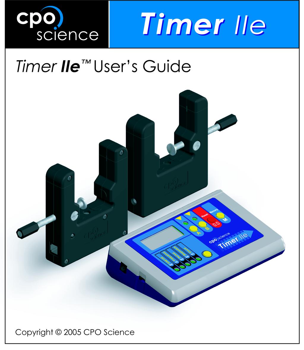
4 Chapter 1: Introduction Making accurate measurements is the key to many good experiments. The CPO Science Timer IIe uses a precision quartz crystal to make time measurements accurate to within seconds and frequency measurements accurate to 0.1 Hertz. The two photogates (included) allow the Timer to be started and stopped by anything that breaks the light beams. This booklet will show you how to use the Timer to measure speed, acceleration, the period of a pendulum, the frequency of sound, and many other quantities. What s New? The Timer IIe (enhanced) and the new photogates feature several improvements over the Timer II kit. The tilted, console-style case makes reading the display much easier and the metal stand allows a variety of positioning options. The robust, internal electronics have not changed. The new photogates feature a rubberized texture for easy, comfortable use and advanced electronics to improve accuracy and reliability. 1

5 Chapter 2: Kit Contents The Timer IIe comes with everything you need to perform accurate experiments. You should have received the following parts. Replacement parts can be ordered using the part numbers given. Table 1: What s in the case? Quantity Description Part Number 1 CPO Science Timer IIe CPO Science Photogate Wall Mount Power Supply Phone cord (1 red, 1 blue) , Timer IIe User s Guide Storage Case (optional) Volt Battery (not included) N/A TIMER USER S GUIDE 2
 generate large voltages that can damage or destroy the Timer.")

6 Chapter 3: Using the Timer Warnings and Precautions Please make note of the following warnings and precautions: WARNING: Do not plug any lines from the telephone system in to the inputs. Telephone rings (also present in modems) generate large voltages that can damage or destroy the Timer. IMPORTANT: Use only the 9V power supply that has the CPO Science name/logo on it with the Timer. Using another supply can damage the Timer or photogates and void your warranty. Inputs A and B are for connecting the photogates or the CPO Science Sound & Waves machine. DO NOT plug telephone equipment, modems or anything else into the inputs, or you risk damaging the Timer and/or the telephone equipment. 3

7 Replacing the 9 V Battery Open the battery compartment by gently pulling back on the latch and removing the compartment door. Remove the old battery. Clip in the fresh 9 V battery and place it inside the battery compartment, then replace the battery door. If the battery door is difficult to close, do not force it. Check that the battery, clip, and wires are seated properly inside the compartment and try again. Using the Timer with two photogates can run down the battery quickly. Use the 9 V power supply instead. The Console The five buttons control the Timer and the lights tell you what the Timer is measuring and displaying, and its units. Pressing the mode switching button will change the mode from one of the five modes to the next one, moving left to right and stepping once for each time the button is pressed. The order is: Interval-Frequency-Period-Stopwatch-Count. After Count, the mode cycles back to Interval. TIMER USER S GUIDE 4
8 Table 2: Timer Buttons and Indicators Feature Mode Button: Mode Lights: A Button: A Light: B Button: B Light The Reset (0.0) Button: The Memory (M) Button: Function The mode button switches the Timer between its five different functions (or modes). The five lights tell you which function the Timer is in. The A button switches the A light on and off, and starts and stops the stopwatch. The A light indicates what the Timer is displaying or doing relative to input A. The B button switches the B light on and off. The B light indicates what the Timer is displaying or doing relative to input B. The reset button initializes the Timer back to zero, or begins a new measurement. It also erases any value in memory. The memory button allows you to display the previous time interval measurements in interval mode. 5

9 The Photogate The photogate uses an invisible beam of infra-red light to start and stop the Timer. The photogates connect to inputs A and B with two telephone cords. When the photogate is working properly, the status light will be lit when the Timer is turned on. If there is nothing obstructing the light beam, the status light will be green. The status light changes to red when you interrupt the light beam. The Timer can work with either one or two photogates connected. For convenience we refer to the photogate plugged into input A as photogate A. and the one connected to input B as photogate B. It does not matter which color wire you use. The wires are electrically identical and the different colors allow you to indentify quickly which is photogate A and which is photogate B. The versatile C-clamp design allows the photogates to be used on many different experiments. TIMER USER S GUIDE 6

10 Overtightening the thumbscrew can flex the photogate body enough that the light emitter and reciever twist out of alignment, causing the photogate to malfunction. Loosening the screw will fix the problem. ONLY TIGHTEN THE THUMBSCREW GENTLY. The photogates connect with ordinary telephone cords. You can get replacements (or longer ones) from almost any hardware or office supply store. Computer data cables have the same (RJ-11) connectors and look like telephone cords but are wired differently inside. USING A DATA CABLE WILL DAMAGE THE PHOTOGATES. Stopwatch Mode The Stopwatch function is the simplest of the different modes. In Stopwatch mode the Timer measures in seconds and is accurate to one hundredth (0.01) of a second from 0.01 to seconds. After one minute the display switches to minutes:seconds format and the display is accurate to whole seconds. The stopwatch can measure times up to 199 minutes and 59 seconds (199:59) The diagram below shows the steps to using the stopwatch mode.. 7
 of a second.")
11 Interval Mode In Interval mode, the Timer uses one or two photogates to electronically start and stop up to three stopwatches. The time measurements are much more precise because the light beam can respond much faster than your finger. Using the photogates, the Timer can measure to one ten-thousandth (0.0001) of a second. The pictures below show how the two photogates can be connected and how the lights control the display of time measurements made with the three stopwatches. TIMER USER S GUIDE 8


12 Interval Mode Behaves like Three Stopwatches The Timer in interval mode works like it has three stopwatches. Stopwatch A starts when the light beam is broken in photogate A and stops when the light beam is unbroken again. Stopwatch A measures the time interval during which the light beam is broken in photogate A. Stopwatch B starts when the light beam is broken in photogate B and stops when the beam is unbroken. Stopwatch B measures the time interval during which the light beam is broken in photogate B. Stopwatch AB is controlled by both photogates. Breaking the beam in photogate A starts the stopwatch and breaking the beam in photogate B stops it. Stopwatch AB measures the time interval between photogate A and photogate B. The Timer can use all three stopwatches simultaneously, allowing you to measure up to three time intervals at once. The lights (and buttons) allow you to choose which of the three stopwatches to show on the display. The A and B lights do not have to be on for the Timer to record measurements. The (A) and (B) lights and the (A) and (B) buttons control how the Timer displays the results from the three different stopwatches you can use. The buttons toggle the lights on and off. The lights tell you which of the three stopwatches is being displayed. Try It With One Photogate Connect a photogate to the input jack (socket) behind the (A) button using one of the telephone cords. You should see the status light on the photogate come on. Put the Timer into Interval mode by pressing the mode button until the Interval light comes on. Push the (A) button to turn on the (A) light. When the (A) light is on, the display shows measurements made with the photogate connected to input A. 9

13 Put your finger across the light beam and watch what happens to the display. The display should start counting as soon as your finger breaks the beam and should stop as soon as you finger is removed from the beam. Once your finger is removed the display shows the time during which the beam was broken. Note that when you break the light beam of the photogate with your finger the status light changes from green to red. When you remove your finger, the status light changes back to green. Try It With Two Photogates With both photogates connected you can measure the time it takes to pass between photogates A and B. The following demonstration shows how. Set the Timer to Interval mode with two photogates connected. Use the A and B buttons to turn both the A and B lights on. Press reset to clear the Timer (be sure the light beams are not blocked when pressing reset). Pass your finger through photogate A first, then B. The display should start counting up the moment you break the beam in photogate A and stop when you break the beam in photogate B. Measuring Speed and Acceleration The Timer can be used in Interval mode to measure the speed of objects of a known size, such as a marble or a car with a flag. Ensure the full diameter of the ball or full width of the flag passes through the light beam. In the case of the car: as the front edge of the flag breaks the light beam, the Timer begins the stopwatch for that photogate. The stopwatch is halted when the flag exits the beam. The average speed through the photogate can be calculated: distan ce speed = time TIMER USER S GUIDE 10

14 In this situation, the distance traveled is equal to the width of the flag, and the time is measured by the Timer. Just divide the width of the flag by the time recorded by the Timer for that photogate to get the speed. Don t forget to keep track of units. Acceleration To measure the acceleration of an object you can use two photogates. speed speed acceleration B speed A = = time time The change in speed can be found by calculating the speed of the object at each photogate (as shown above) and taking the difference. The time between photogates is recorded by the Timer in Stopwatch AB. Remember to keep track of units. Measuring Frequency The Timer can measure the frequency of anything that breaks the light beams in the photogates regularly, or the frequency of signals applied to the inputs, such as from the Sound and Waves machine. The highest frequency that can be measured is 19,999 Hz and the lowest is 0.1 Hz. For very low frequencies (<100 Hz) it is more accurate to use period mode, measure the period (T), and invert (f = 1/T). 11
15 Some other uses for frequency mode Frequency mode can be used to measure: the angular speed of a rotating gear the frequency of a vibrating string the RPM of the CPO Science Electric Motor or Ripcord Generator Measuring Period The Timer can measure the period of signals which are connected to the inputs. The photogates can provide the signals (such as with the Pendulum) or the Sound and Waves experiment can provide the signals. The Timer measures period in seconds and can measure the period of the signal in input A or the period of the signal in input B. Period Updates Every Other Cycle You will notice that the period only updates every third time the Pendulum crosses the light beam. This is because the Timer averages over two periods before updating the display. The averaging technique corrects for errors that occur when the photogate is not placed at the exact center of the swing. A Pendulum Crosses Twice Per Cycle You will also notice that the Timer measures the half period of the Pendulum. This is because the pendulum breaks the light beam twice per cycle. The Timer does not know it is seeing a pendulum; all it knows is the period of the breaking of the light beam. Using Count The Timer has a counting feature that counts whenever anything breaks the light beam, or sends a signal. There are two independent counters: A and B. The counters can each count up to 19,999. The Reset button has a double action for count mode. Pressing Reset once causes the counter to stop counting and freezes the display. This is useful for counting things within a fixed time interval. Pressing Reset again will reset the counter back to zero. TIMER USER S GUIDE 12

16 Advanced Functions: The Memory Button You may have noticed that you do not have to press RESET to start a new time measurement. The Timer automatically resets each stopwatch as soon as something breaks the light beam again. If you do not press RESET, the Timer remembers the last time measurement for each of the three stopwatches (A, B, AB). Holding down the memory button lets you see the last values. Make two successive measurements of the time through photogate A and then look at both. Holding down the memory button with the A light on shows the last value for the time through photogate A. Holding down the memory button with the B light on shows the last value for the time through photogate B. Holding down the memory button with both A and B lights on shows the last value for the time from photogate A to photogate B. Advanced Functions: Timing Multiple A to B Events The Timer can keep track of elapsed time from photogate A to photogate B where there may be multiple passes through photogate B. As long as there has been no reset, the A-to-B stopwatch will show the time between the last break of photogate A and the last break of photogate B. This means you can break photogate B multiple times and get increasing elapsed times between A and B. The analogy with a marathon race illustrates how this property of the Timer is useful. Everyone starts through photogate A at the same time. The Timer displays each individual runner s time as they pass through photogate B. 13
17 Chapter 4: Technical Information The CPO Science Timer has the following technical specifications: Time reference: Input voltage: Power source Sensor Inputs: Interval: Frequency: Period: Stopwatch: Count: FCC Compliance: 20 MHz quartz crystal, 0.4 microsecond internal resolution, second display resolution 9 V DC/500 ma minimum (center tip positive) Supplied 9 V DC power supply or 9 V battery Two TTL falling edge triggered inputs using RJ-11 connectors Gate A, Gate B, and Interval A-to-B photogate timing with second resolution, three independent memories, and 19,999 second range Dual channel plus frequency differences (A, B, A-B, B-A) to 19,999 Hz with 0.1 Hz resolution Dual channel (A or B) period measurement to 19,999 seconds with bi-period averaging 0.01 second resolution to seconds and 1 second resolution to 199 minutes, 59 seconds (199:59) Dual channel (A or B) counters to 19,999 each channel This equipment has been tested and found to comply with the limits for a class A digital device, persuant to part 15 of the FCC rules. These rules are designed to provide reasonable protection against harmful interference when the equipment is operated in a commercial environment. The equipment generages and uses radio frequency energy and, if not installed and used in accordance with the instruction manual, may cause harmful interference to radio communications. TIMER USER S GUIDE 14
18 Power Sources Using two photogates drains batteries quickly; two photogates in continuous use can drain a 9 V battery in just a few hours. It is better to use the AC adapter if you are using both photogates. The first sign of a low battery is that the photogates will not work properly. If the battery is low, the status light will not come back on after the light beam is unbroken. Either replace the battery with a fresh one or switch to using the AC adapter. Troubleshooting Table 3: Troubleshooting the Timer Symptom Nothing happens when you slide the switch to the On position What to Do Move the switch back and forth a few times. If you are using the battery, try using the AC adapter - you may need to replace the battery. If you are using the power supply, try using a battery - the outlet may not be working. Try the power supply from another Timer unit. An error is displayed when using photogates Press Reset after making sure all the light beams are unbroken and the status light is green for each photogate. Check the battery - a weak battery can cause errors. Sometimes bright lights or sunlight can trigger the detector. Try shading the photogate with your hand or repositioning it. 15
19 Technical Details: The Error Display The error display is how the Timer signals that there has been a measurement fault. Different causes can create measurement faults in each of the five modes. In almost every case pressing RESET (with all light beams unbroken) will fix the problem. Sometimes new batteries are needed. In very few cases the measurement capacity of the Timer has been exceeded. A disconnected photogate or low batteries are the most common faults. The Timer senses whether a photogate is connected by the presence of a light beam signal whenever the RESET button is pressed. Pressing RESET with the light beam blocked will cause a fault. The fault can be corrected by pressing RESET again with the light beam unblocked. It is possible (but highly unlikely) that the time interval exceeded the maximum of 19,999 seconds (5 hours, 33 minutes). Frequency measurements are good up to 19,999 Hz. Higher frequencies will either generate an error (HI-F) or result in an erratic measurement. Period measurements are limited to 19,999 seconds, after which the Timer will generate an error. Stopwatch measurements are limited to 199 minutes and 59 seconds. Longer time intervals will result in an error. The counter can only count up to 19,999, after which the Timer will give an error. Software Updates and Website Information You can find more information, such as answers to frequently asked questions and updates to documentation for the CPO Science Timer at the CPO Science Support website: You can also sign up at the website to receive when updates become available. TIMER USER S GUIDE 16
20 Warranty Information CPO Science warranties this instrument against defects in materials and workmanship for a period of one year. Repair and/or replacement parts can be obtained from CPO Science by sending the damaged or defective parts to: CPO Science 26 Howley Street, 3rd Floor Peabody, MA support.cpo.com
PHOTOGATE 0662I WITH PULLEY ATTACHMENT User s Guide
 PHOTOGATE 0662I WITH PULLEY ATTACHMENT User s Guide Figure 1. The Photogate with Pulley Attachment CENTRE FOR MICROCOMPUTER APPLICATIONS http://www.cma-science.nl Description The Photogate 0662i is a traditional
FUNTRONIX SCORE-N-TIME TM GAMEROOM EDITION ELECTRONIC SCOREBOARD WITH REAL ALARM CLOCK & DATE. OPERATING MANUAL Model SNT-125G
 FUNTRONIX SCORE-N-TIME TM GAMEROOM EDITION ELECTRONIC SCOREBOARD WITH REAL ALARM CLOCK & DATE OPERATING MANUAL Model SNT-125G Revision: October 27, 2015 1 Thank you for purchasing a Funtronix SCORE-N-TIME
ProHUNTER OWNERS MANUAL
 TM ProHUNTER OWNERS MANUAL TM 400-597-1 1 400-597-1 2 TM SPORTDOG PROHUNTER 2400 REMOTE TRAINER INSTRUCTION MANUAL Thank you for purchasing the ProHunter 2400, one of the finest training systems available
impact VC-500LR Monolight INSTRUCTIONS
 impact lighting equipment and accessories VC-500LR Monolight INSTRUCTIONS Congratulations on your purchase of the Impact VC-500LR Monolight. We feel that it will contribute much to your photographic skill
ELEMENTARY LABORATORY MEASUREMENTS
 ELEMENTARY LABORATORY MEASUREMENTS MEASURING LENGTH Most of the time, this is a straightforward problem. A straight ruler or meter stick is aligned with the length segment to be measured and only care
User's Guide. Wireless AC Circuit Identifier. Models RT30 and RT32
 User's Guide Wireless AC Circuit Identifier Models RT30 and RT32 Introduction Congratulations on your purchase of Extech s Model RT30 (914Mhz) or RT32 (869MHz) Wireless AC Circuit Identifier. The detector
UR200SI / UR200WE ENGLISH
 ENGLISH Hersteller Wörlein GmbH Tel.: +49 9103/71670 Gewerbestrasse 12 Fax.: +49 9103/716712 D 90556 Cadolzburg Email. info@woerlein.com GERMANY Web: www.woerlein.com UR200SI / UR200WE ENVIRONMENTAL PROTECTION
GC-1032 Metal Detector OWNER S MANUAL
 GC-1032 Metal Detector OWNER S MANUAL 1 With your GC-1032 metal detector, you can hunt for coins, relics, jewelry, gold, and silver just about anywhere. The detector comes with high sensitivity and strong
iphone 6 Chargeport REPAIR GUIDE Version Edition
 iphone 6 Chargeport REPAIR GUIDE Version 1 2016 Edition IPHONE 6 CHARGEPORT REPAIR GUIDE LCD AND DIGITIZER REPLACEMENT RiAna Soto Repair Training Specialist rsoto@cellairis.com FOR EVERY REPAIR MAKE SURE
TLS-3A. Telephone Line Simulator. User Manual , Rev. B Covers Model TLS-3A-01
 User Manual TLS-3A Telephone Line Simulator 40-400-00010, Rev. B Covers Model TLS-3A-01 Teltone Corporation 22121-20th Avenue SE Bothell, Washington 98021-4408 USA Phone: 1-800-426-3926 or 425-487-1515
Wireless AC Circuit Identifier
 User's Guide Wireless AC Circuit Identifier Models RT30 and RT30-E 99 Washington Street Melrose, MA 02176 Phone 781-665-1400 Toll Free 1-800-517-8431 Visit us at www.testequipmentdepot.com Back to the
CONTENTS Preparation Functions and Indications Operation
 CONTENTS Features 3 Preparation Parts of the detector 4 Assembling the detector 4 Adjusting the search coil 6 Installing the batteries 6 Using the headphones 7 Functions and Indications Parts of the control
CCR24T CCR24R. User s Guide WIRELESS TRANSMITTER SYSTEM WARRANTY SERVICE CARD WARRANTY CARD
 WARRANTY SERVICE CARD WARRANTY CARD PRODUCT NAME Wireless Transceiver System PERIOD MODEL NAME CCR24GEN YEAR PURCHASE DATE.. 200_ From the date of WARRANTY PERIOD.. 200_ purchase. CUSTOMER S ADDRESS :
QUANTUM Qflash T2 / X2 OPERATING INSTRUCTIONS
 QUANTUM Qflash T2 / X2 OPERATING INSTRUCTIONS 1.0 DESIGNATIONS T2 AND X2 1. Removable Reflector, two positions Normal and Wide angle. 2. Flash-tube 2A. Modeling Lamp (for Model X2 only) 3. Bounce Head,
С 800 CASSIDA C 800 HIGH SPEED COIN COUNTER
 С 800 CASSIDA C 800 HIGH SPEED COIN COUNTER This manual contains important information on safety measures and operational features. Please read it carefully before operating your coin counter, and keep
Multi-Channel In-Out Thermometer with Cable Free Sensor and RF Clock
 Multi-Channel In-Out Thermometer with Cable Free Sensor and RF Clock MAIN FEATURES: MAIN UNIT GB MODEL: RMR182 USER'S MANUAL INTRODUCTION Congratulations on your purchase of the RMR182 Multi- Channel In-Out
Sound n Lights. Monitor. with Dual Receivers. Model Number: 71624
 Sound n Lights Monitor with Dual Receivers Model Number: 71624 For proper setup and use, please read these instructions. Please keep this instruction sheet for future reference, as it contains important
Proximity-Sensor Counter Installation Instruction Model: MRC-PRO
 Proximity-Sensor Counter Installation Instruction Model: MRC-PRO NYS DOT Approval SYSDYNE CORP. 1055 Summer St. 1 st Floor Stamford, CT 06905 Tel: (203)327-3649 Fax: (203)325-3600 Contents: Introduction...
S ENSORLINK INSTALLATION MANUAL
 S ENSORLINK INSTALLATION MANUAL The SensorLink Transmitter (#7610) and SensorLink Receiver (#7611) are designed to work with Davis Instruments Weather Monitor II and the Weather Wizard III to enable wireless
PART #MSP-DCCPPWS Plasma Wall Swing-Out (PWS) Wall Mount
 Wall Mount") I N S T R U C T I O N M A N U A L PART # Plasma Wall Swing-Out (PWS) Wall Mount The wall mount is a rugged, versatile, and installer-friendly solution to unique display mounting requirements. With the
I N S T R U C T I O N M A N U A L PART # Plasma Wall Swing-Out (PWS) Wall Mount The wall mount is a rugged, versatile, and installer-friendly solution to unique display mounting requirements. With the
Installing Your Electronic Deadbolt
 Ultra Security Plus Electronic Deadbolt Installation Instructions http://www.hberger.com/video-gallery/electronic-deadbolt New Installation Lock Location Preparation (Skip this section if you door has
Sound n Lights Monitor
 Sound n Lights Monitor Model Number 71565 Please read these instructions and keep them for future reference. Includes two AC adaptors to power the transmitter and receiver. The receiver also runs on battery
Digital Electronic Thermostat With RF
 RT300RF Manual Altech 005_89 06/05/2014 08:56 Page 1 Digital Electronic Thermostat With RF Instruction Manual Model No ALTHC015 RT300RF Manual Altech 005_89 06/05/2014 08:56 Page 2 2 ALTHC015 INSTRUCTION
Ambient Weather F007PF 8-Channel Wireless Water Thermometer User Manual
 Ambient Weather F007PF 8-Channel Wireless Water Thermometer User Manual Table of Contents 1 Introduction... 2 2 Getting Started... 2 Parts List... 2 2.1 Water Thermometer Sensor Set Up... 2 3 Glossary
GFL3000 Ground Fault Locator Operating Instructions
 GFL3000 Ground Fault Locator Operating Instructions WARNING Read and understand the instructions before operating this unit. Failure to do so could lead to injury or death. The Armada Technologies GFL3000
AUDI A8 D3 REPLACING THE OUTSIDE DRIVER DOOR HANDLE
 AUDI A8 D3 REPLACING THE OUTSIDE DRIVER DOOR HANDLE The keyless entry system in the D3 is a great feature. If you have the car key fob in your pocket, putting your hand under the door handle will unlock
ENCORE 200 VHF Bass Wireless Microphone System
 ENCORE 200 VHF Bass Wireless Microphone System Nady Wireless Systems are type accepted under FCC rules parts 90, 74 and 15. The device complies with RSS-210 of Industry & Science Canada. Operation is subject
Lap Timer System RCA60. Instruction Manual. Farringdon Instruments Limited. Farringdon Instruments Limited
 Lap Timer System RCA60 Instruction Manual Farringdon Instruments Limited Farringdon Instruments Limited Unit 9 Oriel Court Omega Park Alton Hampshire GU34 2YT Telephone 01420 541591 Facsimile 01420 587212
Portable All-Band Radar and Laser Detector RD950. Owner s Manual
 Portable All-Band Radar and Laser Detector RD950 Owner s Manual K40 Consult Don t like to read manuals? Call our experienced K40 Consultants. We ll explain the whole thing. 800.323.5608 K40 ELECTRONICS
Quick Start Guide. Contents
 1 Quick Start Guide Contents Powering on the Machine Login/Password Entry Jaw Set Up High Security Cut by Code High Security Jaw Set Up Edge Cut Cut by Code Edge Cut Cut by Decode Cutter Replacement Tracer
Seite 2 Standard-Empfänger. EN Operation Instructions
 sign lux DE Bedienungsanleitung Seite 2 Standard-Empfänger EN Operation Instructions Page 10 Standard receiver FR Mode d emploi Page 18 Récepteur standard NL Gebruiksaanwijzing Pagina 26 Standaard ontvanger
RLS2. Owner s Manual. Portable All-Band Radar and Laser Detector with GPS Technology
 RLS2 Owner s Manual Portable All-Band Radar and Laser Detector with GPS Technology K40 Consult Don t like to read manuals? Call our experienced K40 Consultants. We ll explain the whole thing. 800.323.5608
ARROW SAW PRECISE CUT 8000 RPM WITH DUST COLLECTING ATTACHMENT INSTRUCTION BOOK MODEL NO
 ATTENTION If any components of this unit are broken or the unit does not operate properly, please contact Cabela s Customer Service. Retail Store Purchases: 1-800-905-2731 (U.S. & Canada) Catalog and Internet
TONE TATTOO ANALOG MULTI-EFFECT PEDAL featuring METAL MUFF, NEO CLONE & MEMORY TOY
 TONE TATTOO ANALOG MULTI-EFFECT PEDAL featuring METAL MUFF, NEO CLONE & MEMORY TOY Congratulations on your purchase of the fully analog Electro-Harmonix TONE TATTOO, the first true multi-effect from Electro-Harmonix!
SRVODRV REV7 INSTALLATION NOTES
 SRVODRV-8020 -REV7 INSTALLATION NOTES Thank you for purchasing the SRVODRV -8020 drive. The SRVODRV -8020 DC servo drive is warranted to be free of manufacturing defects for 1 year from the date of purchase.
VARIABLE SPEED WOOD LATHE
 MODEL MC1100B VARIABLE SPEED WOOD LATHE INSTRUCTION MANUAL Please read and fully understand the instructions in this manual before operation. Keep this manual safe for future reference. Version: 2015.02.02
WEL-200 O P E R A T I N G I N S T R U C T I O N S W I R E L E S S E D G E L I N K
 O P E R A T I N G I N S T R U C T I O N S WEL-200 TM W I R E L E S S E D G E L I N K 4564 Johnston Parkway, Cleveland, Ohio 44128 P. 800 426 9912 F. 216 518 9884 Sales Inquiries: salessupport@emxinc.com
SoundPals. DAC-24 User Guide. Stereo D-to-A converter
 SoundPals DAC-24 User Guide Stereo D-to-A converter Printing History SoundPals DAC-24 D-to-A converter Rev. N/C SEPTEMBER 2016 Printed in U.S.A. Part Number 08-2044-00 The information contained in this
OPERATING INSTRUCTIONS ARE ON PAGE 5. SECTION 2 Technical Data Transmitter Unit. RVHT 2 MULTI-FIT Programmable R/F Thermostat-Pair SECTION 1
 OPERATING INSTRUCTIONS ARE ON PAGE 5 RVHT 2 MULTI-FIT Programmable R/F Thermostat-Pair SECTION 1 This Programmable Ravenheat R/F controlled room Thermostat RVHT 2, consists of 2 items: a Mobile Transmitter
Ambient Weather WS-40 Wireless Indoor / Outdoor Thermometer
 Ambient Weather WS-40 Wireless Indoor / Outdoor Thermometer Table of Contents 1. Introduction... 1 2. Getting Started... 1 2.1 Parts List... 1 2.2 Thermometer Sensor Set Up... 1 2.3 Display Console Set
Hardware Installation. Do this first:
 1 Do this first: Hardware Installation Need some help? Here s what you ll need: 4 AA Batteries Phillips screwdriver Visit us online. support.remotelock.com We re here to help. 1 (877) 254 5625 support@remotelock.com
Digital Wireless Weather System
 Digital Wireless Weather System Thermometer, Hygrometer and Heat Index with Remote Sensor Leading the Way in Accuracy 1458 Instruction Manual C H CHANNEL Congratulations on your purchase of the Taylor
RADIO ANTI TWO-BLOCK SYSTEM
 BB-550 TM RADIO ANTI TWO-BLOCK SYSTEM INSTALLATION MANUAL GREER Company 1918 East Glenwood Place, Santa Ana, CA 92705 Tel: (714) 259-9702 FAX (714) 259-7626 BB-550 TM Radio Anti Two-Block System PN W250000
Multi Drop Bus 5-Tube Coin Changer. Series. Service Manual B D A C E SAT
 Multi Drop Bus 5-Tube Coin Changer Series Service Manual DIS C/C A C E MOD B D SAT AUT 2 TABLE OF CONTENTS Page 1 Outline... 3 2 Product Model Names... 4 3 General Specifications... 5 4 Detailed Specifications...
This manual applies to the WT-RC-Ex receiver when used to locate all makes and models of 22 Hz and Wavetrak coded transmitters.
 This manual applies to the WT-RC-Ex receiver when used to locate all makes and models of 22 Hz and Wavetrak coded transmitters. The Wavetrak WT-RC-Ex receiver kit comes with the following pieces of equipment:
The Instructions should be read, prior to commencing the installation, failure to follow these instructions will void your warranty.
 Low Voltage System The Platinum Low Voltage lighting system can power up to 120 candle pods depending on the length of cables used during the installation this can reduce the number of pods to 24 per outlet
Assistive Listening Systems. RX-6 User s Guide
 Assistive Listening Systems RX-6 User s Guide Page ii RX-6 User s Guide Copyright Information Contents Introduction 1 Controls 2 Installing Batteries 3 Operation 3 Tuning the RX-6 4 Changing Preset Channels
QUANTUM Qflash MODEL T OPERATING INSTRUCTIONS
 QUANTUM Qflash MODEL T OPERATING INSTRUCTIONS 1.0 DESIGNATIONS 1. Removable Reflector, two positions Normal and Wide angle. 2. Flash-tube 3. Bounce Head, Rotates 180º 4. Swivel Head, Rotates ± 90º 5. Sensor
PIECAL 211 Automated RTD Calibrator Operating Instructions. Product Description. Practical Instrument Electronics
 Product Description Easy to use With the PIECAL 211 you can check & calibrate all your RTD instruments and measure RTD Sensors. Automatic indication of connections on the display for simple hookups. Take
Iphone 5 Glass/Lcd REPAIR GUIDE. Version Edition
 Iphone 5 Glass/Lcd REPAIR GUIDE Version 1 2016 Edition IPhone 5 Glass/LCd REPAIR GUIDE RiAna Soto Repair Training Specialist rsoto@cellairis.com FOR EVERY REPAIR MAKE SURE TO COMPLETE, INITIAL, AND HAVE
ONYX Deskset HD. Portable Video Magnifier User s Guide. Freedom Scientific, Inc Revision A
 ONYX Deskset HD Portable Video Magnifier User s Guide Freedom Scientific, Inc. www.freedomscientific.com 440829-001 Revision A PUBLISHED BY Freedom Scientific 11800 31 st Court North St. Petersburg, Florida
VZ-EA2 Product Manual
 VZ-EA2 Product Manual IMPORTANT SAFETY INFORMATION 1. Read this entire manual before assembling and using the VirZOOM. VirZOOM can only be used safely if it is assembled, maintained and used properly.
Ambient Weather WS-0270 Wireless Indoor / Outdoor Thermometer with Indoor Humidity User Manual
 Ambient Weather WS-0270 Wireless Indoor / Outdoor Thermometer with Indoor Humidity User Manual Table of Contents 1 Introduction... 1 2 Getting Started... 1 2.1 Parts List... 2 2.2 Recommend Tools... 2
RESIDENTIAL MOTORIZED STORAGE UNIT
 BY V-BRO PRODUCTS RESIDENTIAL MOTORIZED STORAGE UNIT Model: GGR220 INSTALLATION AND OPERATING INSTRUCTIONS Distributed Exclusively by V-BRO PRODUCTS For technical questions and replacement parts, please
Series 1. Remote. Multiple Mode Remote Controlled Electro Stimulation Control Unit. User Manual
 Series 1 Remote Multiple Mode Remote Controlled Electro Stimulation Control Unit User Manual Issue 5.0 March 2010 WELCOME 4 2 Key Features 4 WHAT'S IN THE KIT? 5 Contents 5 Quick Guide 5 Before Use 5 USING
NEO CAR AUDIO. Neo AUXiN AUX INPUT INTERFACE. Instruction Manual
 NEO CAR AUDIO Neo AUXiN AUX INPUT INTERFACE Instruction Manual IMPORTANT NOTE Neo AUXiN Dip switch positions MUST be set BEFORE any other step is taken. Otherwise, the kit will not operate properly. See
Frequency Calibrator with Totalizer
 Frequency Calibrator with Totalizer Model 942 0.001% accuracy Locked to high stability crystal Six real world ranges 1 to 20000 counts-per-hour to 2000.0 counts-per-minute 0.01 to 999.99 Hz to 9999.9 Hz
FCC STATEMENT This device complies with part 74, Subpart H of the FCC rules. Operation is subject to the following two conditions: (1)This device may
This device may") FCC STATEMENT This device complies with part 74, Subpart H of the FCC rules. Operation is subject to the following two conditions: (1)This device may not cause harmful interference and (2) This device
FCC STATEMENT This device complies with part 74, Subpart H of the FCC rules. Operation is subject to the following two conditions: (1)This device may not cause harmful interference and (2) This device
Wall Mount Assembly and Mounting Guide (55 /84 )
") Microsoft Surface Hub Wall Mount Assembly and Mounting Guide (55 /84 ) For mounting on a wall with wood studs These instructions assume wood-stud wall construction with 2-by-4 studs spaced 16 inches apart,
Microsoft Surface Hub Wall Mount Assembly and Mounting Guide (55 /84 ) For mounting on a wall with wood studs These instructions assume wood-stud wall construction with 2-by-4 studs spaced 16 inches apart,
Micro Wizard Instructions K1 KIT ASSEMBLY INSTRUCTIONS With Remote Start Switch
 K1 KIT ASSEMBLY INSTRUCTIONS With Remote Start Switch Kit Contents: (If you have ordered the Quick Mount or have a Best Track, the contents of your kit will differ from this list. Please refer to the mounting
VARIABLE SPEED WOOD LATHE. Model DB900 INSTRUCTION MANUAL
 VARIABLE SPEED WOOD LATHE Model DB900 INSTRUCTION MANUAL 1007 TABLE OF CONTENTS SECTION...PAGE Technical data.. 1 General safety rules....1-3 Specific safety rules for wood lathe.....3 Electrical information.4
Weatheradio Alert ( ) Features Faxback Doc. # 47648
 Features Faxback Doc. # 47648") (120-0140) Features Faxback Doc. # 47648 Your REALISTIC WEATHERADIO ALERT is specially designed to receive weather reports broadcast 24 hours a day by the National Weather Service. Special stations provide
(120-0140) Features Faxback Doc. # 47648 Your REALISTIC WEATHERADIO ALERT is specially designed to receive weather reports broadcast 24 hours a day by the National Weather Service. Special stations provide
USER MANUAL ENGLISH 1450 COIN COUNTER & SORTER
 USER MANUAL ENGLISH 1450 COIN COUNTER & SORTER INTRODUCTION ENGLISH Thank you for purchasing the Safescan 1450 coin counter and sorter. For proper use and maintenance, we advise to read this user manual
SuperTrack Parts List
 SuperTrack Parts List [indicates number for 6 lane tracks] SuperTrack Installation Instructions www.supertimer.com 1-800-654-2088 1 Track Instruction Manual (this booklet) 2 Start sections [3] Start Gate
R PROFLAME Instruction Book Collection
 9.956.028 R00 584 PROFLAME Instruction Book Collection 4-17 18-29 584 PROFLAME System 30-39 Appendix: DIP SWITCH NUMBER (0=ON 1=OFF) 40-41 4-17 Fig. 1 The SIT is a device that allows, in conjunction with
 GENERAL OPERATIONAL PRECAUTIONS WARNING! When using electric tools, basic safety precautions should always be followed to reduce the risk of fire, electric shock and personal injury, including the following.
HD-CXENVL-FDR Envelope Feeder Assembly and Operations Guide
 HD-CXENVL-FDR Envelope Feeder Assembly and Operations Guide Rev. 12-12-16 1 Table of Contents DESCRIPTION OF FUNCTION... 3 Time-out (out of paper) Feature... 3 PREPARING THE HD-CX1600/1700 (C9x1) PRINTER...
SPRINT 5000 BOOKLETMAKER OPERATION MANUAL
 SPRINT 5000 BOOKLETMAKER OPERATION MANUAL Sprint5000HCS-USA.doc3.doc Page 1 01/05/2002 CONTENTS 1. Introduction. 2 2. Specification. 2 3. Initial setting up. 3 4. Operation. 4 4.1 Loading staples. 5 4.2
USER'S MANUAL DMR-6700
 USER'S MANUAL Multimeter True RMS DMR-6700 CIRCUIT-TEST ELECTRONICS www.circuittest.com Introduction This meter measures AC/DC Voltage, AC/DC Current, Resistance, Capacitance, Frequency (electrical & electronic),
BULLETIN # B
 Page 1 of 9 BULLETIN # B-18-2002 From: Parts and Service Division Date: February 14, 2002 To: All Authorized Service Agencies SUBJECT: Convection Oven Controller Troubleshooting MODELS AFFECTED: All Garland
Safety Warnings Features Specifications Instrument Layout Operation Preparation AC Current Measurement How to Use Peak Hold Function How to Use The
 Safety Warnings Features Specifications Instrument Layout Operation Preparation AC Current Measurement How to Use Peak Hold Function How to Use The Frequency Selector Switch How to Use Data Hold Function
18600 Angular Momentum
 18600 Angular Momentum Experiment 1 - Collisions Involving Rotation Setup: Place the kit contents on a laboratory bench or table. Refer to Figure 1, Section A. Tip the angular momentum apparatus base on
IPhone 7 Plus Digitizer/LCD REPAIR GUIDE. Version Edition
 IPhone 7 Plus Digitizer/LCD REPAIR GUIDE Version 1 2016 Edition IPhone 7 Plus Digitizer/LCD REPAIR GUIDE LCD AND DIGITIZER REPLACEMENT RiAna Soto Repair Training Specialist rsoto@cellairis.com FOR EVERY
TABLE OF CONTENTS DRAWINGS
 TABLE OF CONTENTS Bifold Door Adjustment Procedures...pg 4 Bifold Door Maintenance...pg 6 Safety Concerns...pg 9 Troubleshooting...pg 10 Bifold Door Maintenance Checklist...pg 11 DRAWINGS EK 1880 Bifold
INSTRUCTION BOOKLET AND WARRANTY INFORMATION 6 BENCH GRINDER
 INSTRUCTION BOOKLET AND WARRANTY INFORMATION 6 BENCH GRINDER Part No.: SW1250 PLEASE READ CARE AND SAFETY INSTRUCTIONS BEFORE USE SPECIFICATIONS Part No.: SW1250 Input Voltage: 240V Frequency: 50Hz Rated
Computer Tools for Data Acquisition
 Computer Tools for Data Acquisition Introduction to Capstone You will be using a computer to assist in taking and analyzing data throughout this course. The software, called Capstone, is made specifically
Frequency Calibrator with Totalizer
 99 Washington Street Melrose, MA 02176 Phone 781-665-1400 Toll Free 1-800-517-8431 Frequency Calibrator with Totalizer Model 942 0.001% accuracy Locked to high stability crystal Six real world ranges 1
M170 Belt Pack Transmitter OPERATING INSTRUCTIONS and trouble-shooting guide LECTROSONICS, INC. Rio Rancho, NM
 M170 Belt Pack Transmitter OPERATING INSTRUCTIONS and trouble-shooting guide LECTROSONICS, INC. Rio Rancho, NM INTRODUCTION Thank you for selecting the M170 Series transmitter. The M170 Series transmitters
PIECAL Model 541 Frequency Calibrator with Totalizer Operating Instructions
 PIECAL Model 541 Frequency Calibrator with Totalizer Operating Instructions Easy to use With the Model 541 you can check & calibrate all your frequency instruments and measure flow sensors. Take it into
1250 Automatic Traverse
 Adams-Maxwell Winding Systems Operating Manual 1250 Automatic Traverse Adams-Maxwell Winding Systems Page 2 Adams-Maxwell 4740 Calle Carga Camarillo, CA 93012 Phone: (323) 936-8028 Fax: (888) 936-8042
F AN-ASPIRATED W IRELESS T EMPERATURE/HUMIDITY S TATION
 F AN-ASPIRATED W IRELESS T EMPERATURE/HUMIDITY S TATION INSTALLATION MANUAL The Fan-Aspirated Wireless Temperature/Humidity Station, referred to in this manual as the Aspirated Temp/Hum Station, combines
Quick Start Guide. HMa-941. Plug-On Transmitter. For FCC Part 74 licensed operators
 Quick Start Guide HMa-941 Plug-On Transmitter Digital Hybrid Wireless U.S. Patent 7,225,135 For FCC Part 74 licensed operators Fill in for your records: Serial Number: Purchase Date: This guide is intended
Radiant 3000F Video Light (Cat. No. 6052)
") Fantasea Line Radiant 3000F Video Light (Cat. No. 6052) Instruction Manual 1 TABLE OF CONTENTS TABLE OF CONTENTS... 2 DISCLAIMER... 3 INTRODUCTION... 3 GENERAL INFORMATION... 3 SPECIFICATIONS... 4 INCLUDED
Fantasea Line Radiant 3000F Video Light (Cat. No. 6052) Instruction Manual 1 TABLE OF CONTENTS TABLE OF CONTENTS... 2 DISCLAIMER... 3 INTRODUCTION... 3 GENERAL INFORMATION... 3 SPECIFICATIONS... 4 INCLUDED
Schlage Control Smart Locks
 Schlage Control Smart Locks with Engage technology User guide Schlage Control Smart Locks with Engage technology User Guide Contents 3 Warranty 4 Standard Operation 4 Operation from the Inside 4 Operation
2017 CASIO COMPUTER CO., LTD.
 MA1710-E 2017 ASIO OMPUTER O., LT. Operation Guide 5535 ongratulations upon your selection of this ASIO watch. ENGLISH To ensure that this watch provides you with the years of service for which it is designed,
GFL-1000 User Manual Ground Fault Locator
 GFL-Series User Manual V1.1 GFL-1000 User Manual Ground Fault Locator Contents Contents... 1 1 Declaration of Conformity... 3 2 Introduction... 3 3 Equipment Information... 3 3.1 Safety Precautions...
GPNP Inc. NT384 NT1 User Manual. Revision /6/2002. Information in this guide is subject to change without notification.
 GPNP Inc. NT384 NT1 User Manual Revision 1.00 17/6/2002 Information in this guide is subject to change without notification. Copyright 2002 GPNP Inc. U.S.A. IMPORTANT SAFETY INSTRUCTIONS When using your
IS7705. Installation & Operation Manual AUDIO INTEGRATION KIT. TranzIt LINK
 GET CONNECTED Installation & Operation Manual AUDIO INTEGRATION KIT IS7705 Note to Readers, The information contained within the following documentation is subject to change without notice. Features discussed
MW3105 DIGITAL CLAMP MULTIMETER
 MW3105 DIGITAL CLAMP MULTIMETER 2 M MW3105 A 01 INTRODUCTION 1.1 - Unpacking and inspection Upon removing your new Digital Clamp Meter from its packing, you should have the following items: 1. Digital
A510S Operation Manual
 A510S Operation Manual REV 1.1 1 Table of Contents 1 General Information 1-1 Description 1-2 Potential Operational Hazards 1-3 Technical Specifications 1-4 Instrument Overview 1-5 Function Summary 2 How
This manual is valid for the TM. In TENSity 5000 TENS Stimulator. This user manual is published by Current Solutions, LLC
 INSTRUCTION MANUAL This manual is valid for the TM In TENSity 5000 TENS Stimulator This user manual is published by Current Solutions, LLC Current Solutions, LLC does not guarantee its contents and reserves
200Amp AC Clamp Meter + NCV Model MA250
 User's Guide 200Amp AC Clamp Meter + NCV Model MA250 Introduction Congratulations on your purchase of this Extech MA250 Clamp Meter. This meter measures AC Current, AC/DC Voltage, Resistance, Capacitance,
R-400A Telemetry Receiver For Law Enforcement Tracking
 R-400A Telemetry Receiver For Law Enforcement Tracking COVERS THE ENTIRE 216.000-219.999MHz BAND IN 1kHz STEPS FOR QUICK AND ACCURATE FREQUENCY SELECTION SUPER SELECTIVE 8 POLE SSB CRYSTAL FILTER FOR GREATER
ET-302TS. Owner's Manual
 ET-302TS Owner's Manual Welcome to the World of Einstein E-Collar ET-302TS Owner's Manual Remote Education Collar Thank you for purchasing the Einstein Remote Education Collar from E-Collar Technologies,
PIECAL 311 Automated Universal RTD Calibrator Operating Instructions. Product Description
 Product Description Easy to use With the PIECAL 311 you can check & calibrate all your RTD instruments and measure RTD Sensors. Automatic indication of connections on the display for simple hookups. Take
Installation Instructions
 Installation Instructions Garage Door Opener Radio Controls Model 5010 (300 mhz) \ 5012 (310 mhz) Single Button Transmitters Model 5100-01 (300 mhz) \ 5102-01 (310 mhz) Receivers WARNING: Disconnect operator
PR-216. High Performance Personal Receiver PR-216 OPERATOR S MANUAL
 PR-216 OPERATOR S MANUAL PR-216 High Performance Personal Receiver 357 West 2700 South Salt Lake City, Utah 84115 Phone: (800) 496-3463 Fax: (801) 484-6906 http://www.comtek.com TABLE OF CONTENTS Introduction...
Fletcher F-3000 / F-3100 Accessory Laser Kit
 Fletcher F-3000 / F-3100 Accessory Laser Kit Shown Assembled on F-3000 Machine Product Warranty The Fletcher-Terry Company warrants the product purchased to be free from defects in parts and workmanship
Fun PhotoMaker. Product may vary from picture above.
 Fun PhotoMaker Product may vary from picture above. The Creative Effects Fun PhotoMaker is designed to be used in very bright lighting conditions. Please save these instructions for future reference. Adult
igeacom User Guide V2.0
 Quality Care through innovative technology igeacom User Guide V2.0 IgeaCare Systems Inc. 5650 Tomken Road, Unit #9, Mississauga, Ontario, L4W 4P1, Canada Tel: 905.361.6225 Fax: 905.361.6209 www.igeacare.com