Transferring wavefront measurements to ablation profiles. Michael Mrochen PhD Swiss Federal Institut of Technology, Zurich IROC Zurich
|
|
|
- Bartholomew Heath
- 6 years ago
- Views:
Transcription
1
2 Transferring wavefront measurements to ablation profiles Michael Mrochen PhD Swiss Federal Institut of Technology, Zurich IROC Zurich
3 corneal ablation Calculation laser spot positions Centration Calculation ablation profile Eye Tracking Wavefront sensing Performance Laser Centration during measurement photoablation Patient Eye Biological response wound healing
4 corneal ablation Calculation laser spot positions Centration Calculation ablation profile Eye Tracking Wavefront sensing Predictability of the refractive outcome Performance Laser Centration during measurement photoablation Patient Eye Biological response wound healing
5 corneal ablation Calculation laser spot positions Centration Calculation ablation profile Wavefront sensing Centration during measurement Accommodation Tear Film Refractive errors Pupil Size Opacity of media Age Eye Tracking Performance Laser photoablation Patient Eye Biological response wound healing
6 Patients expectations Is it save and predictablil? Correction for far or near distance monovision / presbyopia high expectations on visual performance Cost / service ratio

7 corneal ablation

8 corneal ablation
9 Preview!!!! See also: Mirko Jankov (Poster session) Can dry eye influence the wavefront measurement Takashi Fujikado (Sunday) Wavefront sensing and the tear film
10 corneal ablation Calculation laser spot positions Centration Calculation ablation profile Eye Tracking Wavefront sensing Fixation Target line of sight pupil size Performance Laser Centration during measurement photoablation Patient Eye Biological response wound healing
11 corneal ablation Calculation laser spot positions Centration Calculation ablation profile Wavefront sensing Centration during measurement Optical Setup System calibration Wavelength Zernike calculation Dynamic range of sensor Eye Tracking Performance Laser photoablation Patient Eye Biological response wound healing
12 Chromatic aberrations Φ = 1D F 486 nm d 588 nm C 656 nm Wavefront sensors usually work in the near infrared wave length > 750 nm
13 Preview!!!! See also: Larry Thibos (Hot Topics) Does Chromatic Aberration Hinder or Help?


14 Wavefront sensing ~ 96 spots over a 7 mm pupil ~ 1100 spots over a 7 mm pupil
15 corneal ablation Calculation laser spot positions Centration Calculation ablation profile Eye Tracking Wavefront sensing Centration during measurement Optical eye model K-Readings Topography of the cornea Biometric data of the eye Performance Laser photoablation Patient Eye Biological response wound healing

 y 2 2 2 ( r) = R2 ( r r0 )")
 = r 2 D = D before D after = ( n 1)")
16 Ablation profiles Ablation profile Subjective Refraction Pupil size corneal curvature age female / mail patien expectations y ( r) = R1 ( r r0 ) y ( r) = R2 ( r r0 ) Optical zone radius r 0 2 ( r0 ), 0 r 0 ( n 1) D r a( r) = r 2 D = D before D after = ( n 1) 1 R 1 1 R 2
17 Ablation profiles. the corneal topography information specifying corneal shape has very little effect on the desired ablation depth for an optimal refraction. Stanley Klein, J Opt. Soc. Am A (1999)
18 Ablation profiles Wavefront guided treatments. the first surface of the cornea and internal optics partially compensate for each other's aberrations and produce an improved retinal image. it shows the limitation of corneal topography as a guide for new refractive procedures and provides a strong endorsement of the value of ocular wave-front sensing for those applications.. Pablo Artal, J. Vis. (2001)

19 Ablation profiles wavefront aberrations of the internal structures Corneal wavefront aberrations Total wavefront aberrations

20 Ablation profiles Converting wavefronts into corrections 1st - order approximation! Wavefront inversion 2 µm 2 µm 2 µm 2 µm Pupil diameter 6 mm Pupil diameter 6 mm Ablations profile shift vertical axis [mm] horizontal axis [mm] ablation depth [µm] 12 µm 6 µm Pupil diameter 6 mm Ablations profil conversion 6 µm W ( x, y) a( x, y) = n = n 1 6 µm Pupil diameter 6 mm
![Ablation profiles Total wavefront Wavefront of higher orders Pre-OP Post-OP 6 months vertical axis [mm]](/docs-images/74/70320411/images/21-1.jpg "vertical axis [mm] Ablation profile used!")
![10 8 6 4 2 10 8 6 4 2 2 4 6 8 10 horizontal axis [mm] 2 4 6 8 10 horizontal axis [mm] 36 34 32 30 28 26](/docs-images/74/70320411/images/21-3.jpg "24 22 20 18 16 14 12 10 8.0 6.0 4.0 2.")
21 Ablation profiles Total wavefront Wavefront of higher orders Pre-OP Post-OP 6 months vertical axis [mm] vertical axis [mm] Ablation profile used! horizontal axis [mm] horizontal axis [mm] ablation depth [µm] classical ablation profile ablation depth [µm]
22 Ablation profiles a ray that is less bent when it enters the eye is expected to intersect the lens much further away form the axis. the spherical aberration is expected to be much higher in the operated eye. Fabrice Manns, SPIE Ophthalmic Technologies XI (2001)
23 Ablation profiles f 1
24 Ablation profiles f f f
25 Ablation profiles because of individual interactions of the aberrations in the ocular components, a combination of corneal and total aberration measurements is critical to understand the individual outcomes, and by extension, to designing customized ablation algorithms. Susana Marcos, IOVS (2001)
26 Preview!!!! See also: Susana Marcos (Sunday) From theoretical laser ablation profile design ro real outcomes: implications for optimized corneal refractive correction Steve Burns (Hot topics) What s better than a perfect optical correction?
27 corneal ablation Calculation laser spot positions Centration Calculation ablation profile Eye Tracking Wavefront sensing Centration during measurement Overlapping of spots assumed ablation depth per pulse corneal shape factors thermal heating Performance Laser photoablation Patient Eye Biological response wound healing
![Ablation depth [µm] Principles of of laser-tissue interaction 1.4 1.2 1.0 0.8 0.6 0.4 0.2 Tissue removal Threshold process Ablation threshold @ 193 nm 50-60 mj/cm 2 0.](/docs-images/74/70320411/images/28-2.jpg "0 10 100 1000 Radiant exposure [mj/cm²) Planned ablation profile Ablation threshold ~ 50 mj/cm 2 Central ablation depth of a single laser spot ~ 0.5 microns Ablation diameter of a single spot 0.5-1.")
28 Ablation depth [µm] Principles of of laser-tissue interaction Tissue removal Threshold process Ablation 193 nm mj/cm Radiant exposure [mj/cm²) Planned ablation profile Ablation threshold ~ 50 mj/cm 2 Central ablation depth of a single laser spot ~ 0.5 microns Ablation diameter of a single spot mm Ablation diameter of a single spot mm

29 corneal ablation Treatment zone Optical zone Spot overlapping Laser pulses
30 corneal ablation Small laser beam Pulse ablation profile Large laser beam Pulse ablation profile Achieved profile Attempted profile on the cornea Achieved profile

31 Example Coma-like Aberration Ablation depth 0.5µm 0.25µm 0.125µm C7 = 0.5µm Pulse diameter 1.5mm 1.0mm 0.5mm

32 Example Example 6th 6th order order astigmatism astigmatism 1.5mm Pulse diameter 1.0mm C23 = 0.25µm 0.5mm 0.5µm Ablation depth 0.25µm 0.125µm
33 Treatment time!! Reducing the spot diameter by a factor of 2 results in an increase of the treatment time by a factor of 4. treatment time ~ ( spot diameter 2 )
34 corneal ablation Calculation laser spot positions Centration Calculation ablation profile Eye Tracking Wavefront sensing Centration during measurement Fixation Target line of sight pupil size rough corneal surface Performance Laser photoablation Patient Eye Biological response wound healing
35 Centration Difficulty 2 Centration: A task with 6 degrees of freedom Horizontal shifts Vertical shifts Rotation around longitudinal axis (cyclotorsion) Rotation around horizontal axis Rotation around vertical axis Z - distance The coordinate systems used in the measurement (M) and the treatment (T) have to coincide exactly!
36 Centration 2 Types of centration errors: Systematic centration errors causing constant decentration Random (dynamic) centration errors causing the ablation to be smeared
37 Centration Systematic centration errors avoid with precise alignment techniques Random (dynamic) centration errors avoid with active eye tracking
38 Centration Required Accuracy Treat 95% of normal eyes to: Diffraction limit 10 th percentile of rms of normal eyes Same image quality Torsional 3 mm 3 deg 6 deg 29 deg alignment 7 mm 1 deg 4 deg 21 deg Lateral 3 mm 0.21 mm 0.41 mm 0.85 mm centration 7 mm 0.07 mm 0.22 mm 0.62 mm
39 corneal ablation Calculation laser spot positions Centration Calculation ablation profile Eye Tracking Wavefront sensing Centration during measurement Sapling rate / Latency Resolution Pupil Size Paraxial errors of entrance pupil Performance Laser photoablation Patient Eye Biological response wound healing

40 Eye - tracking The eye moves during treatment
41 Eye - tracking How does latency cause positioning errors? Latency Image Acquisition Image Transfer Image Processing Position Control Ablation image Eye Tracker x/y Scanner Device beamsplitter α/β Camer a Scanner mirror ablation beam Laser infrared illumination Eye
42 Eye - tracking Image Acquisition Image Transfer Image Processing Position Control Ablation Eye Tracker Scanner Device Camera Laser
43 Eye - tracking Image Acquisition Image Transfer Image Processing Position Control Ablation image Eye Tracker Scanner Device Camera Laser
44 Eye - tracking Image Acquisition Image Transfer Image Processing Position Control Ablation image Eye Tracker x/y Scanner Device Camera Laser
45 Eye - tracking Image Acquisition Image Transfer Image Processing Position Control Ablation image Eye Tracker x/y Scanner Device α/β Camera Laser
46 Eye - tracking Image Acquisition Image Transfer Image Processing Position Control Ablation image Eye Tracker x/y Scanner Device α/β Camera Laser
47 Eye - tracking Eye motion Positioning Error Latency Eye Motion during Latency => Positioning Error
48 Eye - tracking Vertical deviation [µm] 400 Vertical deviation [µm] ms latency 4 ms latency Horizontal deviation [µm] Vertical deviation [µm] ms latency Horizontal deviation [µm] Vertical deviation [µm] No tracking Positioning errors increase with increasing latency Horizontal deviation [µm] SMI Horizontal deviation [µm]
49 Preview!!!! More detailed information on the assumptions, stability, and outcomes of different scanning - spot laser parameters such as ablation depth, spot diameter, and eye-tracking latency treatments are presented tomorrow by Michael Bueeler
50 corneal ablation Calculation laser spot positions Centration Calculation ablation profile Eye Tracking Wavefront sensing Centration during measurement Energy stability Beam profile Scanning technology Wavelength Performance Laser photoablation Patient Eye Biological response wound healing
51 Excimer laser corneal ablation Beam profiling / shaping Beam delivery Imaging / focusing optics

52 corneal ablation
53 corneal ablation Calculation laser spot positions Centration Calculation ablation profile Eye Tracking Wavefront sensing Centration during measurement Tissue absorption Laser pulse duration Tissue properties Biomechanical properties of tissue Performance Laser photoablation Patient Eye Biological response wound healing
54 Principles of of laser-tissue interaction Dissoziation and vaporisation Vaporisation Ft h F0 Dissoziation da b l - α z ~e Tissue z
55 Principles of of laser-tissue interaction Radiant exposure (fluence) Absorption Breaking of molecular bonds Increase of temperature Breaking of hydrogen bonds Dissociation and vaporization Tissue removal Stress waves Ablation plume dynamics
56 Ablation depth [µm] Principles of of laser-tissue interaction Tissue removal Threshold process Ablation 193 nm mj/cm Radiant exposure [mj/cm²)

57 Spot cross-section The illumination problem
58 The illumination problem 1.00 Fluence losses z α 0.95 Ae ff y kor(r) F = 150mJ/cm²; R = 6.5 mm F = 150mJ/cm²; R = 7.0 mm F = 150mJ/cm²; R = 7.8 mm F = 150mJ/cm²; R = 8.3 mm r x radius r[mm]
59 corneal ablation Calculation laser spot positions Centration Calculation ablation profile Eye Tracking Wavefront sensing Centration during measurement Epithelium smoothing Flap / Hinge Biomechanical changes DLK Performance Laser photoablation Patient Eye Biological response wound healing
60 Biomechanical effect IOP
61 Biomechanical effect IOP
62 Biomechanical effect IOP
63 Biomechanical effect myopic shift! IOP
64 Biomechanical effect Do we have a method for stiffening the cornea?
65
66
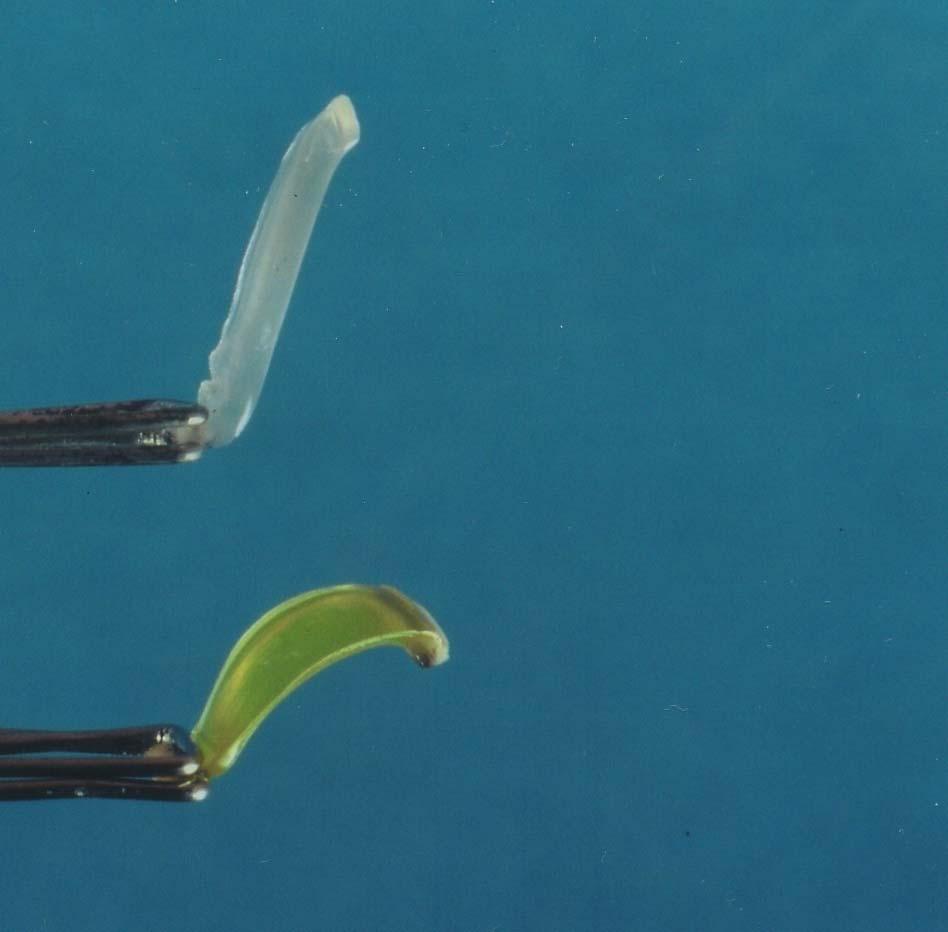
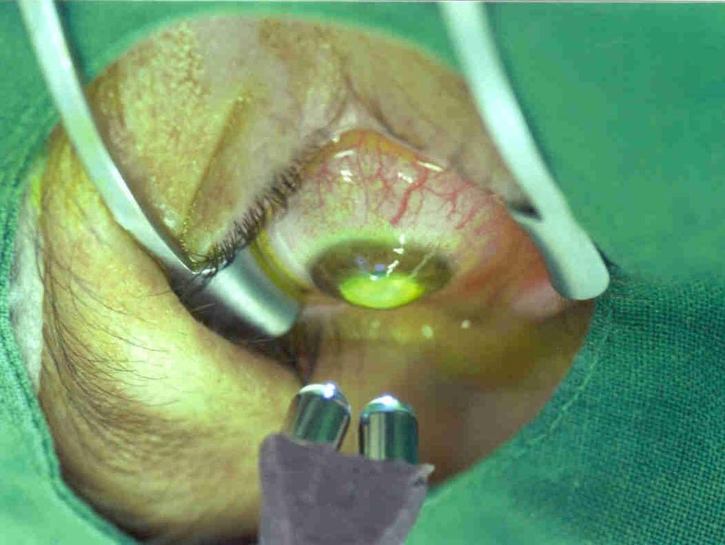
67 Biomechanical effect Cross-linking by UV - light and riboflavin is able to increase Young s module of the cornea by a factor of 5
68 SUMMARY Transfering wavefronts onto the cornea includes complex physical, optical, and biological assumtions that are not fully understood or studied
69 corneal ablation Calculation laser spot positions Centration Calculation ablation profile Eye Tracking Wavefront sensing Further research is required to increase Performance Laser Centration during measurement photoablation Patient Eye Biological response wound healing
70 corneal ablation Calculation laser spot positions Centration Calculation ablation profile Eye Tracking Wavefront sensing Centration during measurement the predictability of the refractive outcomes Performance Laser photoablation Patient Eye Biological response wound healing
71
72
Limits of Higher Order Correction based on Spot Size, Ablation Depth, and Tracker Responsiveness
 Limits of Higher Order Correction based on Spot Size, Ablation Depth, and Tracker Responsiveness Michael Bueeler a,b, Michael Mrochen a,b, Theo Seiler b a Swiss Federal Institute of Technology Zurich,
Surgical data reveals that Q-Factor is important for good surgical outcome
 Surgical data reveals that Q-Factor is important for good surgical outcome Michael Mrochen, PhD Michael Bueeler, PhD Tobias Koller, MD Theo Seiler, MD, PhD IROC AG Institut für Refraktive und Ophthalmo-Chirurgie
Corporate Perspective Alcon Unanswered Technical Challenges that Still Need to be Overcome
 Corporate Perspective Alcon Unanswered Technical Challenges that Still Need to be Overcome Ronald Krueger, MD Refractive Industry Challenges Diagnostic Improvement Optimal Laser Performance Corneal Factors
The Aberration Structure of the Keratoconic Eye
 The Aberration Structure of the Keratoconic Eye Geunyoung Yoon, Ph.D. Department of Ophthalmology Center for Visual Science Institute of Optics Department of Biomedical Engineering University of Rochester
Customized Correction of Wavefront Aberrations in Abnormal Human Eyes by Using a Phase Plate and a Customized Contact Lens
 Journal of the Korean Physical Society, Vol. 49, No. 1, July 2006, pp. 121 125 Customized Correction of Wavefront Aberrations in Abnormal Human Eyes by Using a Phase Plate and a Customized Contact Lens
SCHWIND AMARIS. We have redefined perfection for you
 SCHWIND AMARIS We have redefined perfection for you 2 SCHWIND AMARIS the TotalTech Laser Not only can it do anything it can do it outstandingly well, too. The SCHWIND AMARIS is a TotalTech Laser. It is
Optical Engineering 421/521 Sample Questions for Midterm 1
 Optical Engineering 421/521 Sample Questions for Midterm 1 Short answer 1.) Sketch a pechan prism. Name a possible application of this prism., write the mirror matrix for this prism (or any other common
Lecture 2: Geometrical Optics. Geometrical Approximation. Lenses. Mirrors. Optical Systems. Images and Pupils. Aberrations.
 Lecture 2: Geometrical Optics Outline 1 Geometrical Approximation 2 Lenses 3 Mirrors 4 Optical Systems 5 Images and Pupils 6 Aberrations Christoph U. Keller, Leiden Observatory, keller@strw.leidenuniv.nl
Optical Components for Laser Applications. Günter Toesko - Laserseminar BLZ im Dezember
 Günter Toesko - Laserseminar BLZ im Dezember 2009 1 Aberrations An optical aberration is a distortion in the image formed by an optical system compared to the original. It can arise for a number of reasons
What is Wavefront Aberration? Custom Contact Lenses For Vision Improvement Are They Feasible In A Disposable World?
 Custom Contact Lenses For Vision Improvement Are They Feasible In A Disposable World? Ian Cox, BOptom, PhD, FAAO Distinguished Research Fellow Bausch & Lomb, Rochester, NY Acknowledgements Center for Visual
MEL 80 Excimer Laser. When you want to see better performance
 MEL 80 Excimer Laser When you want to see better performance Reward your practice Invest in the very latest refractive excimer technology! The MEL 80 makes vision correction even safer, more patient-friendly
10/25/2017. Financial Disclosures. Do your patients complain of? Are you frustrated by remake after remake? What is wavefront error (WFE)?
?") Wavefront-Guided Optics in Clinic: Financial Disclosures The New Frontier November 4, 2017 Matthew J. Kauffman, OD, FAAO, FSLS STAPLE Program Soft Toric and Presbyopic Lens Education Gas Permeable Lens
Wavefront-Guided Optics in Clinic: Financial Disclosures The New Frontier November 4, 2017 Matthew J. Kauffman, OD, FAAO, FSLS STAPLE Program Soft Toric and Presbyopic Lens Education Gas Permeable Lens
4th International Congress of Wavefront Sensing and Aberration-free Refractive Correction ADAPTIVE OPTICS FOR VISION: THE EYE S ADAPTATION TO ITS
 4th International Congress of Wavefront Sensing and Aberration-free Refractive Correction (Supplement to the Journal of Refractive Surgery; June 2003) ADAPTIVE OPTICS FOR VISION: THE EYE S ADAPTATION TO
Lecture 4: Geometrical Optics 2. Optical Systems. Images and Pupils. Rays. Wavefronts. Aberrations. Outline
 Lecture 4: Geometrical Optics 2 Outline 1 Optical Systems 2 Images and Pupils 3 Rays 4 Wavefronts 5 Aberrations Christoph U. Keller, Leiden University, keller@strw.leidenuniv.nl Lecture 4: Geometrical
Lecture 2: Geometrical Optics. Geometrical Approximation. Lenses. Mirrors. Optical Systems. Images and Pupils. Aberrations.
 Lecture 2: Geometrical Optics Outline 1 Geometrical Approximation 2 Lenses 3 Mirrors 4 Optical Systems 5 Images and Pupils 6 Aberrations Christoph U. Keller, Leiden Observatory, keller@strw.leidenuniv.nl
Subjective Image Quality Metrics from The Wave Aberration
 Subjective Image Quality Metrics from The Wave Aberration David R. Williams William G. Allyn Professor of Medical Optics Center For Visual Science University of Rochester Commercial Relationship: Bausch
Normal Wavefront Error as a Function of Age and Pupil Size
 RAA Normal Wavefront Error as a Function of Age and Pupil Size Raymond A. Applegate, OD, PhD Borish Chair of Optometry Director of the Visual Optics Institute College of Optometry University of Houston
VATT Optical Performance During 98 Oct as Measured with an Interferometric Hartmann Wavefront Sensor
 VATT Optical Performance During 98 Oct as Measured with an Interferometric Hartmann Wavefront Sensor S. C. West, D. Fisher Multiple Mirror Telescope Observatory M. Nelson Vatican Advanced Technology Telescope
Corneal Asphericity and Retinal Image Quality: A Case Study and Simulations
 Corneal Asphericity and Retinal Image Quality: A Case Study and Simulations Seema Somani PhD, Ashley Tuan OD, PhD, and Dimitri Chernyak PhD VISX Incorporated, 3400 Central Express Way, Santa Clara, CA
PROCEEDINGS OF SPIE. Measurement of low-order aberrations with an autostigmatic microscope
 PROCEEDINGS OF SPIE SPIEDigitalLibrary.org/conference-proceedings-of-spie Measurement of low-order aberrations with an autostigmatic microscope William P. Kuhn Measurement of low-order aberrations with
MicroSpot FOCUSING OBJECTIVES
 OFR P R E C I S I O N O P T I C A L P R O D U C T S MicroSpot FOCUSING OBJECTIVES APPLICATIONS Micromachining Microlithography Laser scribing Photoablation MAJOR FEATURES For UV excimer & high-power YAG
Ron Liu OPTI521-Introductory Optomechanical Engineering December 7, 2009
 Synopsis of METHOD AND APPARATUS FOR IMPROVING VISION AND THE RESOLUTION OF RETINAL IMAGES by David R. Williams and Junzhong Liang from the US Patent Number: 5,777,719 issued in July 7, 1998 Ron Liu OPTI521-Introductory
Overview of Commercially Available Femtosecond Lasers in Refractive Surgery
 Holger Lubatschowski Overview of Commercially Available Femtosecond Lasers in Refractive Surgery The author receives research funds from Ziemer Ophthalmic Systems Group Commercially Available Femtosecond
THE BEST OF BOTH WORLDS Dual-Scheimpflug and Placido Reaching a new level in refractive screening
 THE BEST OF BOTH WORLDS Dual-Scheimpflug and Placido Reaching a new level in refractive screening Clinical Applications Corneal Implant Planning The comes with a licensable corneal inlay software module
Computer Generated Holograms for Optical Testing
 Computer Generated Holograms for Optical Testing Dr. Jim Burge Associate Professor Optical Sciences and Astronomy University of Arizona jburge@optics.arizona.edu 520-621-8182 Computer Generated Holograms
Rediscover quality of life thanks to vision correction with technology from Carl Zeiss. Patient Information
 Rediscover quality of life thanks to vision correction with technology from Carl Zeiss Patient Information 5 2 It was really w Vision defects: Light that goes astray For clear vision the eyes, cornea and
WaveMaster IOL. Fast and Accurate Intraocular Lens Tester
 WaveMaster IOL Fast and Accurate Intraocular Lens Tester INTRAOCULAR LENS TESTER WaveMaster IOL Fast and accurate intraocular lens tester WaveMaster IOL is an instrument providing real time analysis of
WaveMaster IOL. Fast and accurate intraocular lens tester
 WaveMaster IOL Fast and accurate intraocular lens tester INTRAOCULAR LENS TESTER WaveMaster IOL Fast and accurate intraocular lens tester WaveMaster IOL is a new instrument providing real time analysis
3.0 Alignment Equipment and Diagnostic Tools:
 3.0 Alignment Equipment and Diagnostic Tools: Alignment equipment The alignment telescope and its use The laser autostigmatic cube (LACI) interferometer A pin -- and how to find the center of curvature
Design of Large Working Area F-Theta Lens. Gong Chen
 1 Design of Large Working Area F-Theta Lens by Gong Chen 2 ABSTRACT F-Theta lenses are different from normal camera lenses. It is one of the most important parts of laser scanning system. Besides, F-Theta
OPTICAL SYSTEMS OBJECTIVES
 101 L7 OPTICAL SYSTEMS OBJECTIVES Aims Your aim here should be to acquire a working knowledge of the basic components of optical systems and understand their purpose, function and limitations in terms
OPAL. SpotOptics. AUTOMATED WAVEFRONT SENSOR Single and double pass O P A L
 Spotptics The software people for optics UTMTED WVEFRNT SENSR Single and double pass ccurate metrology of standard and aspherical lenses ccurate metrology of spherical and flat mirrors =0.3 to =60 mm F/1
HOYA aspherical IOL with ABC (Aspheric Balanced Curve) Design
 Design") HOYA aspherical IOL with ABC (Aspheric Balanced Curve) Design Contents Basics of asphericity Visual quality and aspheric IOL Features of HOYA ABC Design 2 What is asphericity? Deviating from the spherical
HOYA aspherical IOL with ABC (Aspheric Balanced Curve) Design Contents Basics of asphericity Visual quality and aspheric IOL Features of HOYA ABC Design 2 What is asphericity? Deviating from the spherical
EE119 Introduction to Optical Engineering Fall 2009 Final Exam. Name:
 EE119 Introduction to Optical Engineering Fall 2009 Final Exam Name: SID: CLOSED BOOK. THREE 8 1/2 X 11 SHEETS OF NOTES, AND SCIENTIFIC POCKET CALCULATOR PERMITTED. TIME ALLOTTED: 180 MINUTES Fundamental
Chapters 1 & 2. Definitions and applications Conceptual basis of photogrammetric processing
 Chapters 1 & 2 Chapter 1: Photogrammetry Definitions and applications Conceptual basis of photogrammetric processing Transition from two-dimensional imagery to three-dimensional information Automation
Corneal refrac+ve surgery: Are we trea+ng the wrong loca+on with the wrong correc+on?
 RAA Corneal refrac+ve surgery: Are we trea+ng the wrong loca+on with the wrong correc+on? Raymond A. Applegate, OD, PhD College of Optometry University of Houston Corneal refrac+ve surgery is arguably
Geometric optics & aberrations
 Geometric optics & aberrations Department of Astrophysical Sciences University AST 542 http://www.northerneye.co.uk/ Outline Introduction: Optics in astronomy Basics of geometric optics Paraxial approximation
Testing Aspheric Lenses: New Approaches
 Nasrin Ghanbari OPTI 521 - Synopsis of a published Paper November 5, 2012 Testing Aspheric Lenses: New Approaches by W. Osten, B. D orband, E. Garbusi, Ch. Pruss, and L. Seifert Published in 2010 Introduction
Tutorial Zemax 8: Correction II
 Tutorial Zemax 8: Correction II 2012-10-11 8 Correction II 1 8.1 High-NA Collimator... 1 8.2 Zoom-System... 6 8.3 New Achromate and wide field system... 11 8 Correction II 8.1 High-NA Collimator An achromatic
SpotOptics. The software people for optics OPAL O P A L
 Spotptics The software people for optics UTMTED WVEFRNT SENSR ccurate metrology of standard and aspherical lenses (single pass) ccurate metrology of spherical and flat mirrors (double pass) =0.3 to =50
 Página 1 de 9 TopPage > Eye Care > Diagnostic > Wave-Front Analyzer KR-1W Wave-Front Analyzer KR-1W Perfection for Professionals : KR-1W Topcon, with its wealth of experience in designing and manufacturing
Optical Connection, Inc. and Ophthonix, Inc.
 Optical Connection, Inc. and Ophthonix, Inc. Partners in the delivery of nonsurgical vision optimization www.opticonnection.com www.ophthonix.com The human eye has optical imperfections that can not be
Difrotec Product & Services. Ultra high accuracy interferometry & custom optical solutions
 Difrotec Product & Services Ultra high accuracy interferometry & custom optical solutions Content 1. Overview 2. Interferometer D7 3. Benefits 4. Measurements 5. Specifications 6. Applications 7. Cases
CREATING ROUND AND SQUARE FLATTOP LASER SPOTS IN MICROPROCESSING SYSTEMS WITH SCANNING OPTICS Paper M305
 CREATING ROUND AND SQUARE FLATTOP LASER SPOTS IN MICROPROCESSING SYSTEMS WITH SCANNING OPTICS Paper M305 Alexander Laskin, Vadim Laskin AdlOptica Optical Systems GmbH, Rudower Chaussee 29, 12489 Berlin,
USE OF COMPUTER- GENERATED HOLOGRAMS IN OPTICAL TESTING
 14 USE OF COMPUTER- GENERATED HOLOGRAMS IN OPTICAL TESTING Katherine Creath College of Optical Sciences University of Arizona Tucson, Arizona Optineering Tucson, Arizona James C. Wyant College of Optical
 Telecentric Imaging Object space telecentricity stop source: edmund optics The 5 classical Seidel Aberrations First order aberrations Spherical Aberration (~r 4 ) Origin: different focal lengths for different
Wavefront-Guided Programmable Spectacles Related Metrics
 Wavefront-Guided Programmable Spectacles Related Metrics Lawrence Sverdrup, Sean Sigarlaki, Jeffrey Chomyn, Jagdish Jethmalani, Andreas Dreher Ophthonix, Inc. 23rd February 2007 Outline Background on Ophthonix
Lens Design I. Lecture 5: Advanced handling I Herbert Gross. Summer term
 Lens Design I Lecture 5: Advanced handling I 2018-05-17 Herbert Gross Summer term 2018 www.iap.uni-jena.de 2 Preliminary Schedule - Lens Design I 2018 1 12.04. Basics 2 19.04. Properties of optical systems
Why is There a Black Dot when Defocus = 1λ?
 Why is There a Black Dot when Defocus = 1λ? W = W 020 = a 020 ρ 2 When a 020 = 1λ Sag of the wavefront at full aperture (ρ = 1) = 1λ Sag of the wavefront at ρ = 0.707 = 0.5λ Area of the pupil from ρ =
Light has some interesting properties, many of which are used in medicine:
 LIGHT IN MEDICINE Light has some interesting properties, many of which are used in medicine: 1- The speed of light changes when it goes from one material into another. The ratio of the speed of light in
PROCEEDINGS OF SPIE. Automated asphere centration testing with AspheroCheck UP
 PROCEEDINGS OF SPIE SPIEDigitalLibrary.org/conference-proceedings-of-spie Automated asphere centration testing with AspheroCheck UP F. Hahne, P. Langehanenberg F. Hahne, P. Langehanenberg, "Automated asphere
Digital Wavefront Sensors Measure Aberrations in Eyes
 Contact: Igor Lyuboshenko contact@phaseview.com Internet: www.phaseview.com Digital Measure Aberrations in Eyes 1 in Ophthalmology...2 2 Analogue...3 3 Digital...5 Figures: Figure 1. Major technology nodes
Explanation of Aberration and Wavefront
 Explanation of Aberration and Wavefront 1. What Causes Blur? 2. What is? 4. What is wavefront? 5. Hartmann-Shack Aberrometer 6. Adoption of wavefront technology David Oh 1. What Causes Blur? 2. What is?
OpenStax-CNX module: m Vision Correction * OpenStax
 OpenStax-CNX module: m42484 1 Vision Correction * OpenStax This work is produced by OpenStax-CNX and licensed under the Creative Commons Attribution License 3.0 Abstract Identify and discuss common vision
In recent years there has been an explosion of
 Line of Sight and Alternative Representations of Aberrations of the Eye Stanley A. Klein, PhD; Daniel D. Garcia, PhD ABSTRACT Several methods for representing pupil plane aberrations based on wavefront
Design of a Test Bench for Intraocular Lens Optical Characterization
 Journal of Physics: Conference Series Design of a Test Bench for Intraocular Lens Optical Characterization To cite this article: Francisco Alba-Bueno et al 20 J. Phys.: Conf. Ser. 274 0205 View the article
Focus on performance. The SCHWIND AMARIS product family TREAT
 Focus on performance The SCHWIND AMARIS product family TREAT AMARIS Product Family Our SCHWIND AMARIS product family The absolute best performance from the leader in technology The ever-increasing pace
Causes of refractive error post premium IOL s 3/17/2015. Instruction course: Refining the Refractive Error After Premium IOL s.
 Instruction course: Refining the Refractive Error After Premium IOL s. Senior Instructor: Mounir Khalifa, MD Instructors: David Hardten,MD Scott MacRea,MD Matteo Piovella,MD Dr. Khalifa: Causes of refractive
Principles and clinical applications of ray-tracing aberrometry (Part II)
") UPDATE/REVIEW Principles and clinical applications of ray-tracing aberrometry (Part II) Alfredo Castillo Gómez, MD, PhD 1 ; Antonio Verdejo del Rey, OD 2 ; Carlos Palomino Bautista, MD 3 ; Ana Escalada
UPDATE/REVIEW Principles and clinical applications of ray-tracing aberrometry (Part II) Alfredo Castillo Gómez, MD, PhD 1 ; Antonio Verdejo del Rey, OD 2 ; Carlos Palomino Bautista, MD 3 ; Ana Escalada
CHARA Collaboration Review New York 2007 CHARA Telescope Alignment
 CHARA Telescope Alignment By Laszlo Sturmann Mersenne (Cassegrain type) Telescope M2 140 mm R= 625 mm k = -1 M1/M2 provides an afocal optical system 1 m input beam and 0.125 m collimated output beam Aplanatic
Testing an off-axis parabola with a CGH and a spherical mirror as null lens
 Testing an off-axis parabola with a CGH and a spherical mirror as null lens Chunyu Zhao a, Rene Zehnder a, James H. Burge a, Hubert M. Martin a,b a College of Optical Sciences, University of Arizona 1630
A new approach to the study of ocular chromatic aberrations
 Vision Research 39 (1999) 4309 4323 www.elsevier.com/locate/visres A new approach to the study of ocular chromatic aberrations Susana Marcos a, *, Stephen A. Burns b, Esther Moreno-Barriusop b, Rafael
AgilOptics mirrors increase coupling efficiency into a 4 µm diameter fiber by 750%.
 Application Note AN004: Fiber Coupling Improvement Introduction AgilOptics mirrors increase coupling efficiency into a 4 µm diameter fiber by 750%. Industrial lasers used for cutting, welding, drilling,
Pablo Artal. collaborators. Adaptive Optics for Vision: The Eye's Adaptation to its Point Spread Function
 contrast sensitivity Adaptive Optics for Vision: The Eye's Adaptation to its Point Spread Function (4 th International Congress on Wavefront Sensing, San Francisco, USA; February 23) Pablo Artal LABORATORIO
Vision Research at. Validation of a Novel Hartmann-Moiré Wavefront Sensor with Large Dynamic Range. Wavefront Science Congress, Feb.
 Wavefront Science Congress, Feb. 2008 Validation of a Novel Hartmann-Moiré Wavefront Sensor with Large Dynamic Range Xin Wei 1, Tony Van Heugten 2, Nikole L. Himebaugh 1, Pete S. Kollbaum 1, Mei Zhang
Collimation Tester Instructions
 Description Use shear-plate collimation testers to examine and adjust the collimation of laser light, or to measure the wavefront curvature and divergence/convergence magnitude of large-radius optical
ADVANCED OPTICS LAB -ECEN 5606
 ADVANCED OPTICS LAB -ECEN 5606 Basic Skills Lab Dr. Steve Cundiff and Edward McKenna, 1/15/04 rev KW 1/15/06, 1/8/10 The goal of this lab is to provide you with practice of some of the basic skills needed
Nmark AGV-HPO. High Accuracy, Open Frame, Thermally Stable Galvo Scanner. Highest accuracy scanner available attains singledigit,
 Nmark AGV-HPO Galvanometer Nmark AGV-HPO High Accuracy, Open Frame, Thermally Stable Galvo Scanner Highest accuracy scanner available attains singledigit, micron-level accuracy over the field of view Optical
OPTINO. SpotOptics VERSATILE WAVEFRONT SENSOR O P T I N O
 Spotptics he software people for optics VERSALE WAVEFR SESR Accurate metrology in single and double pass Lenses, mirrors and laser beams Any focal length and diameter Large dynamic range Adaptable for
Sequential Ray Tracing. Lecture 2
 Sequential Ray Tracing Lecture 2 Sequential Ray Tracing Rays are traced through a pre-defined sequence of surfaces while travelling from the object surface to the image surface. Rays hit each surface once
Paper Synopsis. Xiaoyin Zhu Nov 5, 2012 OPTI 521
 Paper Synopsis Xiaoyin Zhu Nov 5, 2012 OPTI 521 Paper: Active Optics and Wavefront Sensing at the Upgraded 6.5-meter MMT by T. E. Pickering, S. C. West, and D. G. Fabricant Abstract: This synopsis summarized
 http://goldberg.lbl.gov 1 To EUV or not to EUV? That is the question. Do we need EUV interferometry and EUV optical testing? 17 Things you need to know about perfecting EUV optics. 2 The main things you
Understanding Optical Specifications
 Understanding Optical Specifications Optics can be found virtually everywhere, from fiber optic couplings to machine vision imaging devices to cutting-edge biometric iris identification systems. Despite
Conformal optical system design with a single fixed conic corrector
 Conformal optical system design with a single fixed conic corrector Song Da-Lin( ), Chang Jun( ), Wang Qing-Feng( ), He Wu-Bin( ), and Cao Jiao( ) School of Optoelectronics, Beijing Institute of Technology,
Solution of Exercises Lecture Optical design with Zemax Part 6
 2013-06-17 Prof. Herbert Gross Friedrich Schiller University Jena Institute of Applied Physics Albert-Einstein-Str 15 07745 Jena Solution of Exercises Lecture Optical design with Zemax Part 6 6 Illumination
OPTI-201/202 Geometrical and Instrumental Optics Copyright 2018 John E. Greivenkamp. Section 16. The Eye
 16-1 Section 16 The Eye The Eye Ciliary Muscle Iris Pupil Optical Axis Visual Axis 16-2 Cornea Right Eye Horizontal Section Zonules Crystalline Lens Vitreous Sclera Retina Macula And Fovea Optic Nerve
Nmark AGV-HP. High Accuracy, Thermally Stable Galvo Scanner
 Nmark AGV-HP Galvanometer Nmark AGV-HP High Accuracy, Thermally Stable Galvo Scanner Highest accuracy scanner available attains single-digit, micron-level accuracy over the field of view Optical feedback
GEOMETRICAL OPTICS AND OPTICAL DESIGN
 GEOMETRICAL OPTICS AND OPTICAL DESIGN Pantazis Mouroulis Associate Professor Center for Imaging Science Rochester Institute of Technology John Macdonald Senior Lecturer Physics Department University of
Focus on performance. The SCHWIND AMARIS product family TREAT
 Focus on performance The SCHWIND AMARIS product family TREAT AMARIS Product Family Our SCHWIND AMARIS product family The absolute best performance from the leader in technology The ever-increasing pace
The optical analysis of the proposed Schmidt camera design.
 The optical analysis of the proposed Schmidt camera design. M. Hrabovsky, M. Palatka, P. Schovanek Joint Laboratory of Optics of Palacky University and Institute of Physics of the Academy of Sciences of
Development of a new multi-wavelength confocal surface profilometer for in-situ automatic optical inspection (AOI)
") Development of a new multi-wavelength confocal surface profilometer for in-situ automatic optical inspection (AOI) Liang-Chia Chen 1#, Chao-Nan Chen 1 and Yi-Wei Chang 1 1. Institute of Automation Technology,
Development of a new multi-wavelength confocal surface profilometer for in-situ automatic optical inspection (AOI) Liang-Chia Chen 1#, Chao-Nan Chen 1 and Yi-Wei Chang 1 1. Institute of Automation Technology,
Fabrication of 6.5 m f/1.25 Mirrors for the MMT and Magellan Telescopes
 Fabrication of 6.5 m f/1.25 Mirrors for the MMT and Magellan Telescopes H. M. Martin, R. G. Allen, J. H. Burge, L. R. Dettmann, D. A. Ketelsen, W. C. Kittrell, S. M. Miller and S. C. West Steward Observatory,
Refractive Power / Corneal Analyzer. OPD-Scan III
 Refractive Power / Corneal Analyzer OPD-Scan III Comprehensive Vision Analysis and NIDEK, a global leader in ophthalmic and optometric equipment, has created the OPD-Scan III, the third generation aberrometer
ECEN 4606, UNDERGRADUATE OPTICS LAB
 ECEN 4606, UNDERGRADUATE OPTICS LAB Lab 2: Imaging 1 the Telescope Original Version: Prof. McLeod SUMMARY: In this lab you will become familiar with the use of one or more lenses to create images of distant
Choices and Vision. Jeffrey Koziol M.D. Thursday, December 6, 12
 Choices and Vision Jeffrey Koziol M.D. How does the eye work? What is myopia? What is hyperopia? What is astigmatism? What is presbyopia? How the eye works How the Eye Works 3 How the eye works Light rays
Adaptive Optics for Vision Science. Principles, Practices, Design, and Applications
 Adaptive Optics for Vision Science Principles, Practices, Design, and Applications Edited by JASON PORTER, HOPE M. QUEENER, JULIANNA E. LIN, KAREN THORN, AND ABDUL AWWAL m WILEY- INTERSCIENCE A JOHN WILEY
ADVANCED OPTICS LAB -ECEN Basic Skills Lab
 ADVANCED OPTICS LAB -ECEN 5606 Basic Skills Lab Dr. Steve Cundiff and Edward McKenna, 1/15/04 Revised KW 1/15/06, 1/8/10 Revised CC and RZ 01/17/14 The goal of this lab is to provide you with practice
Wave Front Topography. ReSeeVit Evolution Topography Module for Modi Topographer
 Wave Front Topography ReSeeVit Evolution Topography Module for Modi Topographer Introduction The aberrations in the central optical zone have a greater effect than those closer to the edge. From an optical
Trust your eyes. Presbyopic treatment methods on the cornea. PresbyMAX Decision criteria and patient s acceptance
 Trust your eyes. Directory Presbyopic treatment methods on the cornea PresbyMAX The Principle PresbyMAX Expectations and Key Factors PresbyMAX Decision criteria and patient s acceptance PresbyMAX Upcoming
Laboratory experiment aberrations
 Laboratory experiment aberrations Obligatory laboratory experiment on course in Optical design, SK2330/SK3330, KTH. Date Name Pass Objective This laboratory experiment is intended to demonstrate the most
Adaptive optics two-photon fluorescence microscopy
 Adaptive optics two-photon fluorescence microscopy Yaopeng Zhou 1, Thomas Bifano 1 and Charles Lin 2 1. Manufacturing Engineering Department, Boston University 15 Saint Mary's Street, Brookline MA, 02446
Optimized Profiles for Astigmatic Refractive Surgery
 14 Optimized Profiles for Astigmatic Refractive Surgery Samuel Arba-Mosquera 1,, Sara Padroni 3, Sai Kolli 4 and Ioannis M. Aslanides 3 1 Grupo de Investigación de Cirugía Refractiva y Calidad de Visión,
Author Contact Information: Erik Gross VISX Incorporated 3400 Central Expressway Santa Clara, CA, 95051
 Author Contact Information: Erik Gross VISX Incorporated 3400 Central Expressway Santa Clara, CA, 95051 Telephone: 408-773-7117 Fax: 408-773-7253 Email: erikg@visx.com Improvements in the Calculation and
CHAPTER 33 ABERRATION CURVES IN LENS DESIGN
 CHAPTER 33 ABERRATION CURVES IN LENS DESIGN Donald C. O Shea Georgia Institute of Technology Center for Optical Science and Engineering and School of Physics Atlanta, Georgia Michael E. Harrigan Eastman
OCULUS Keratograph 4. Topographer. We focus on progress
 OCULUS Keratograph 4 Topographer We focus on progress Ophthalmologist Versatile and precise For me the Keratograph 4 is an indispensable device for diagnosis and surgical planning. Its automatic measurement
Basics Of Retinal Image Quality
 Slide 2 Basics Of Retinal Image Quality Slide 3 The optics of the eye are the first stage of vision. It is an extremely important stage but not the only stage. Slide 4 Broadly There Are Two Components
Optical System Design
 Phys 531 Lecture 12 14 October 2004 Optical System Design Last time: Surveyed examples of optical systems Today, discuss system design Lens design = course of its own (not taught by me!) Try to give some
Using molded chalcogenide glass technology to reduce cost in a compact wide-angle thermal imaging lens
 Using molded chalcogenide glass technology to reduce cost in a compact wide-angle thermal imaging lens George Curatu a, Brent Binkley a, David Tinch a, and Costin Curatu b a LightPath Technologies, 2603
ECEG105/ECEU646 Optics for Engineers Course Notes Part 4: Apertures, Aberrations Prof. Charles A. DiMarzio Northeastern University Fall 2008
 ECEG105/ECEU646 Optics for Engineers Course Notes Part 4: Apertures, Aberrations Prof. Charles A. DiMarzio Northeastern University Fall 2008 July 2003+ Chuck DiMarzio, Northeastern University 11270-04-1
What s New in Ocular Biomechanics?
 What s New in Ocular Biomechanics? The International Congress of Wavefront Sensing & Optimized Refractive Corrections Wavefront Course January 28, 2006 Torrence A. Makley Research Professor Department