IR Flash USER GUIDE. Professional Thermal Image Analysis Software. Manual Version West Cardinal Drive Beaumont, Texas 77705
|
|
|
- Jonah McDaniel
- 6 years ago
- Views:
Transcription


1 West Cardinal Drive Beaumont, Texas IR Flash Professional Thermal Image Analysis Software Manual Version 2.0 Infrared Cameras, Inc W. Cardinal Drive, Beaumont, TX USER GUIDE IR Flash is a registered trademark of Infrared Cameras, Inc. Copyright Infrared Cameras, Inc. All Rights Reserved. Printed in the United States of America.
2 2
3 3 Table of Contents Section 1: Warranty and Disclaimer Certificate Page 3 Section 2: System and Camera Introduction Page 8 2.1: Camera Specifications Page 8 2.2: Before You Begin Page 9 2.3: Software Installation Page 9 2.4: System Set Up Page 10 Section 3: General Outline Page : General Operation Page : Layout Page 12 Section 4: Miscellaneous Features... Page : Introduction Page : Select IR Colormap Page : Image Averaging Page : Zoom Page : Manual Capture Page : Image Display Controls Page : IR Calculator Page 15 Section 5: File Options... Page : Introduction Page : Load Image File Page : Save Image File Page : Save As Page : Save All Page : Export File Page : Printing Page : Setup Page 21
4 4 Section 6: Video Options... Page : Introduction Page : Capture Single Image Page : Capture Image Series Page : Real-time Filtering Page : Display Resolution Page 24 Section 7: Generating Zones... Page : Introduction Page : Zones Menu Choices Page : Clear All Page : Load Settings Page : Save Settings Page : Load Defaults Page 26 Section 8: Zone Management... Page : Introduction Page : Alarms Page : Export Page 28 Section 9: Radiometry... Page : Introduction Page : Radiometric Correction Page 31 Section 10: Camera Menu Options... Page : Introduction Page : Image Touch-up Page : Delete Touch-up Page : Reset Camera Page : Lens Choice Page 33
5 5 Section 1: Warranty and Disclaimer Certificate Infrared Cameras, Inc. maintains a limited warranty on all hardware products supplied as part of the subject camera package. The camera hardware is warranted for a period of one year from date of invoice. Any camera that is determined to be defective within this warranty period will, at the option of Infrared Cameras, Inc. be either repaired or replaced. In no case shall Infrared Cameras, Inc. liability exceed the original product's purchase price and it holds no other obligation or liability than those set forth herein. This warranty does not apply to any component that has been disassembled, tampered with, or altered in any way or to any other component which has been subject to misuse, negligence, abnormal conditions of operation, or accident. Infrared Cameras, Inc. will, at its option, repair or replace any such defective product free of charge if, upon inspection, it proves to be defective in material or workmanship and provided that it is returned to Infrared Cameras, Inc. within the said one-year period. The user shall determine the particular use to which the product shall be applied and Infrared Cameras, Inc. excludes and disclaims any warranty that the product is fit for that use. Infrared Cameras, Inc. accepts no liability in the use and application of the camera. An infrared camera system generates an image based on the heat (energy) signature of the target scene with all the error associated with non-contact radiometric measurements. A thermal infrared camera cannot determine or diagnose faults, problems, or ailments in any form. That determination must be made by the technician applying the camera technology in his/her specific application. It is the responsibility of the user to obtain proper training in the use of the camera for their particular application including a working knowledge and understanding of any inaccuracy that is typically attributed to radiometric measurements. ANY SOFTWARE APPLICATION PROVIDED IN THIS PACAKGE IS PROVIDED "AS IS" WITHOUT WARRANTY OF ANY KIND, EXPRESSED OR IMPLIED. THE ENTIRE RISK LIES WITH THE USER FOR THE ACCURACY AND PERFORMANCE OF THE PROGRAM. The original registered purchaser of this system is granted a limited, non-exclusive
6 license to use the provided Infrared Cameras, Inc software program. This license includes the operation of the program on a single computer at a time. This license does not extend the right to sub-license or make additional copies beyond one copy used as a backup. You are prohibited from copying, duplicating, selling, or otherwise distributing any component within the software package. Infrared Cameras, Inc reserves all rights to its product and retains exclusive ownership and title beyond that expressly granted in this license. The Infrared Cameras, Inc package is self-contained and requires no maintenance beyond maintaining the viability of cabling etc. Ensure that the lens glass is protected from finger smudges and any object that can scratch the lens surface. This warranty does not include any damage done to the surface of the lens. To clean the lens, simply use a soft dry cloth. WARNING The camera is controlled by the software application and should never be unplugged from the computer while the software is running. The user should exit the software program normally before the camera is unplugged. This will safely shut the camera down. This is analogous to turning your computer off through the Windows software versus just hitting a switch to turn it off. Failure to follow this process may result in the need for the manufacturer to re-calibrate the camera system and this failure is not covered under this warranty. 6 Technical support is offered free of charge to all registered users of Infrared Cameras, Inc. system for one year from date of invoice. Whenever you require technical support you may be asked to provide the serial number of your package before support is granted. We suggest you thoroughly read the User s Manual before you call for assistance. If the User s Manual does not answer your questions please call Infrared Cameras, Inc. If you are having problems with the software please note any errors messages you receive and have them available at your call. User support is available by phone, or in person at the offices of Infrared Cameras, Inc. office during normal working hours. User support is free of charge on issues relating to interpretation of the help files, the proper operation of the software, routine maintenance and warranty service. Consultation is generally not available through this user support service on computer and operating system problems, image interpretation problems, fault diagnosis, system modifications or application specific issues, particularly those outside the field of this program. Infrared Cameras, Inc. reserves the right to determine, at its sole discretion, the extent of user support made available to any user.
7 7
8 8 Section 2: System and Camera Introduction 2.1: Introduction The Infrared Cameras, Inc package includes a state of the art thermal infrared imaging radiometer that is unique in design offering an integrated process monitoring imaging system that includes the camera unit, and a dedicated software program. The core technology used in the system is the latest in thermal imaging technology using a microbolometer / focal plane array, Vanadium Oxide technology base ensuring the best thermal and spatial resolution in the industry. All control functionality is built into the software making sure that the Infrared Cameras, Inc package as versatile as can be developed for any and all process monitoring and control applications. The data signal and communications is accomplished via the USB 2.0 port on the host computer. Camera configuration and operation control is accomplished via this line by the IR Flash software package. Both the data stream and the communication protocol is a proprietary format developed and controlled by Infrared Cameras, Inc. The following information is for the ICI 9320P, the most common camera model at the time of writing. For information about other models, please contact your sales or technical representative. Base IR Camera Manufacturer Technology Material Spectral Response Contrast/Brightness Model ICI 9320 P Infrared Cameras, Inc. Microbolometer Vanadium Oxide 7-14 um Software Controlled Data Output Digital USB 2.0 Thermal Time Constant Thermal Sensitivity Frame Rate Pitch Size Optics Array size Focus 14 ms <30 mk 30 fps 17 um 25mm with 22 FOV array Manual Controlled
9 9 Camera Specification The standard 25mm lens is a high quality F1.0 optic ensuring the highest image quality possible. The lens was chosen with a field of view that optimizes the general process control application. We also have a variety of optional of lenses that can be substituted in specific applications. The system complies with UL/IEC , CSA C22.2 No , IEC only when used with a Computer and power supply that comply with the UL/IEC standard (i.e. A UL Safety Mark), and the Tripp-Lite model IS250HG isolation transformer with a rated supply voltage, Frequency, Power (from Isolation Transformer) of: 120 V, 60 Hz, 2.2 A. It is recommended that the camera system be returned to Infrared Cameras, Inc, at minimum, once every six months and, at maximum, of every twelve months for recalibration. 2.2: Before You Begin 1 Examine the items for shipping damage. If damage is found, before proceeding, contact the delivering carrier's agent and proceed under his/her instructions. 2 Have the insurance agent inspect the damage and arrive at an agreement to repair or replace the damaged item. 3 If replacement or repairs are required, call the engineering office of Infrared Cameras, Inc. as soon as possible for return authorization. In the case of damage, be sure to repackage it in the original shipping carton before shipping. 2.3: Software Installation The installation of this software program is made easy with the use of the installation program "INSTALL" provided on the program disk or USB flash drive. Place the program disk into your CD or DVD drive in your computer (or plug the USB into a USB port) and the installation program will automatically start if the auto-run feature of your drive is enabled. If the install does not automatically start or you are using USB, go to My Computer and double-click on the letter of the drive that contains the installation CD or USB. Next, find and double-click on the Install program icon. Once the install program has started, you will be guided through installation process. When the INSTALL is done the program will be completely installed and a note will appear
10 telling you that the installation is complete. Hit any key and you are ready to begin running the IR Flash program : System Set-Up: There is one main connector and mating cable supplied as part of the Infrared Cameras, Inc. camera system package. That cable is a standard USB 2.0 cable and must be connected to the back plate of the camera unit before operation. In order for the camera and software to connect properly, the camera must be connected to the PC before starting the software. Please wait for the camera to be recognized by the PC and then open IR Flash.
11 11 Section 3: GENERAL OUTLINE 3.1: General Operation The main operating screen will be referred to as the Main Menu Screen throughout this manual. This screen is the first permanent screen that appears when entering the program and is where all user activity will originate. The Main Menu and Control Bar options were organized to break the program into several logical functional groups. These groups will be introduced in detail in subsequent chapters. There is a chapter devoted to each Main Menu choice or an appropriate Control Bar option. First note that before a complete menu presentation is available, you must load an image into the software system or have the camera running in live video mode. Once the camera is plugged into the USB port on the computer this live video should commence. To load an image simply select the LOAD option from the File Main Menu selection and make a file choice as discussed in the File Chapter.

12 12 3.2: Layout The layout of the software is based on one main screen shown above. The main image display area is located in the top left quadrant of the screen with control features found in the main menu line main screen and appropriate sites within the main screen. To view the image shown on the main screen at full-screen resolution, double click the left mouse button while on the image. To return to the normal main screen display, again double click the left mouse button on the image.

13 13 Section 4: Miscellaneous Features 4.1: Introduction The following is a listing of several features found in IR Flash that do not require a separate chapter to describe. The Miscellaneous Chapter lists these features as you might find them on the main screen. 4.2: Select IR Color Map In many situations, it is advantageous to view black and white images in the color scale. In fact, many image processing users select their equipment specifically based on its ability to add false color to black and white imagery. The Color Palette section allows you to completely control the color palette by which the current image is displayed, saved, and printed. The Color palette selection control is a drop down menu located to the top and right of the image display area as shown below.

14 14 4.3: Image Averaging The Image Average button will average all the images from the camera into a single displayed image. The Image Averaging control is located at the top left of the main image display area. Adjust the number of frames you want averaged. 4.4: Zoom The Zoom function allows the zooming of the image data currently on screen and is set by the employing the Zoom Slider control. This control is found to the left of the image display area just below the Image Averaging control. 4.5: Manual Capture Along the bottom of the Image display screen you will find a Pause button and a Capture button. The Pause button will simply Pause continuous image display and show the image where the Pause button was pressed. In contrast, the Capture button will capture an image from the Live display and move it to the captured image group shown to the right center of the main screen. You can capture as many images as needed and save them once your imaging activity is complete. You can move through the captured images using the slider controls located to the bottom of the capture image group display. Additionally, you can move an image in the captured group to the main image display by moving the cursor over the desired image and clicking the left mouse button. To return to live video, select the Live Video Icon at the bottom of the main image display.
. If this button is marked, the display will occur in the AGC mode.")
15 15 4.6: Image Display Control To the right of the image display area are a group of controls used to fine-tune the way the images are presented on screen. At the bottom of these controls is an AGC radio button (Automatic Gain Control). If this button is marked, the display will occur in the AGC mode. If not set, the Center and Span Slider controls will activate. The user will then have complete control of how this image is displayed. The temperature numbers will not change however, how these temperature are represented in the image will change (the color or shade of grey used for a particular temperature may change). 4.7: IR Calculator IR Flash includes a calculator that provides the specialist a resource to determine the theoretical radiometric effects of Emissivity, Reflection, and Transmission on radiometric temperature values. Additionally, the second half of the Calculator allows the user the ability to adjust imaging parameters from an optical point of view. The IR Calculator is found under the Tools main menu choice: The right half of the Calculator screen provides the input and output controls for Radiometry including Wiens Law values and the Planck Equation plot. The right side contains the input and output controls for the optics portion of the calculator.

16 16 4.8: Apply Color to All Images Under the Tools menu option is Apply Color to All Images. This will apply any changes made with the Color Palette and the Max/Min range in the center of the window to all of the images in the Images window in the lower left of the window. 4.9: GPS Meta-Data IR Flash software currently supports the USGlobalsat Corporate model BU-353S4 USB GPS receiver to record GPS meta-data (longitude, latitude, and altitude at the time the image is taken). The BU-353S4 uses the SiRF Star IV chip for GPS communication. While other USB GPS devices with the same chip may possibly work, this model is the only one guaranteed to be compatible with IR Flash. Recording the GPS meta-data is enabled as soon as the device is plugged in and recognized by the computer. When recognized, a notification will temporarily appear in the IR Flash window to confirm. Data recorded and added to the saved images includes the longitude, the latitude, altitude, and direction of travel.
17 17 North-Up Image Rotation On the Loading and Saving tab of the File >> Setup menu option is Automatically rotate images if GPS information is found. When enabled, images that include GPS location data will automatically be rotated with North in the image up.
18 18 Section 5: File Options 5.1: Introduction The series of File Control functions that will be described below are provided to allow you to bring images into the system and manage their display. These File Control features are found in the first of the menu line items found at the top of the main screen page. The File selection group consists of the following main sub-menu options: Load Image Save Image Save As Save All Export Print Setup Exit
19 19 5.2: File Menu Choice: Load Image File The Load selection is used to recall images that have previously been stored as digital data files on some storage media. The first step is to specify the file name of the image you wish to load into the program. A File Choice Window, as described below, will appear listing all files saved under the appropriate file format. Make your selection as described in the File Choice Window discussion. The Load function knows if the image you are loading is a single image or a series of images (See Series). The File Choice Window provides the opportunity to browse through the image files currently on disk and make the image file selection through menu control. Note that the File Choice Window is a standard Windows dialog box and operates accordingly. Of particular interest is the List File Type field. This section allows you to select which file formats you wish to access. To make a file choice you must gain control over the appropriate File, Directory, and Drive subwindows. This is simply done by placing the cursor within the sub-window and proceed with the selection process. Once in the File sub-window for example, scroll through the file names listed, by using the cursor on the scroll bar on the right side of the window. By making a selection on ".." in the Directory sub-window, additional directories will be listed. Upon selection of a new directory a corresponding list will appear for the image files in that directory. An alternate drive can also be accessed using the drive sub-window by pressing the appropriate designation such as "A". When a file of interest has been found, place the highlight at the file name location and click the left mouse button. When the image file has been selected the name will appear in the current file field. By pressing the OK button the file will be loaded and displayed on the image screen. The Cancel button can be used to exit the window without making a file choice.

20 20 5.3: File Menu Choice: Save Image File The Save function allows you to archive any image brought into the program by storing it on the storage media of your choice. When the Save selection is made, a File Choice Window will appear with a prompt to assist you in entering a filename for the new image file. At the prompt enter the filename without the extension. As with Load Image, you must select which one of the many file formats available the image will be saved under. 5.4: File Menu Choice: Save As The Save As option allows you to save the current image under a new file name. This allows you to make duplicate files without disturbing the original data file. 5.5: File Menu Choice: Save All The Save All feature will save the entire image package currently in service. This feature will save these as a series.

.")
21 21 5.6: File Menu Choice: Export File You can export image data to two file types. The first is a MS Excel spread sheet file at a resolution that is allowed by Excel. The second file type is a CSV file which is an ASCII text file with the image placed in 240 rows of data with each row containing 320 data temperature data points (pixels). Image Data Exported to Excel Image data Exported to CSV file
22 22 5.7: File Menu Choice: Printing The Printing option allows you print the current active image. Printing will be accomplished using defined parameters specified in the configuration section for your printer. Printing will occur in the color palette set in the program and will be placed on the page as defined by you in the Print dialog box. Set the size and location parameters you wish the image printed with and depress the OK button. 5.8: File Menu Choice: Set Up This feature allows you to fine tune the setup of the program including certain graphical presentations, the way Zones are saved, etc.
23 23 Section 6: Video Options 6.1: Introduction There are several sub-menu options found under the Video Main Menu choice. These functions are ordered by their ability to manage or manipulate the live video data. The choices found under this menu option is: Capture Single Image Capture Image Series Quad Resolution Real-time Filtering Standard Resolution Double Resolution 6.2: Video Menu Choice: Capture Single Image This menu sub-option allows you to capture an image from the video display and place it in the Captured Image Group (labeled 'Images') shown at the lower left of the main image display. 6.3: Video Menu Choice: Capture Image Series IR Flash allows the user to capture a Series of images. Whenever you wish to capture a new image data set click on the Capture Image Series selection from the Video main menu choice. Once this selection is made and live video is running a red Record Button is displayed under the main image display. When this button is depressed a series of images is captured to the Capture Image Group. When you are done simply depress the black Stop Button (also found at the bottom of the main image display).
24 24 The user can play back the Series as often as needed by selecting the Playback option button under the Series sub-menu choice. When the video is in the capture mode and control buttons are displayed at the bottom of the main image display, use these control buttons, as shown in the above image, to move through the series as desired. 6.4: Video Menu Choice: Real-Time Filtering Often the best judge of image quality is the human eye. The development of image processing technology has provided the ability to manipulate an image to aid the observer in his or her judgment. The Real-Time Image Filtering features of the program offer the user a basic capability in Digital Image Processing. Convolutions are a special case of image enhancement techniques known as spatial filtering. Spatial filtering is typically used for edge or boundary enhancement, noise reduction prior to edge or object detection, or to simply make the image look better. When this sub-menu option is chosen a dialog box will be displayed from which you can pick what filters you want applied to the live video images. Low Pass Gaussian Smoothing Laplacian 1 Median Laplacian 2
25 25 6.5: Video Menu Choice: Display Resolution The resolution of the data coming from the camera is at an array count of 320 pixels stored in 240 lines. Under Standard Resolution the image display takes from the data directly from the camera. The Double Resolution options converts the image to a 640x480 smoothed array. While the displayed image is still shown at 320x240, the display takes the data from an image array 4 times as large. This, in many cases, greatly improves the quality of the image display. The Quad Resolution doubles the image array again.

26 26 Section 7: Generating Zones 7.1: Introduction Zones are regions of interest within or on your image data that are marked and configured by you. You can add, delete, and set-up each zone to function in variety of ways. The area at the bottom left of the screen provides the user interface for each zone for a total of 48 possible. The statistics are shown in this interface dialog as well as a Properties button. You can thumb through the zones in place by using the scroll bar next to the three Zone Display panels shown at the bottom left of the main screen. 7.2: Zones Menu Choices The third main menu choice is the Zones selection which provides a series of sub-menu options to manage the Zones on the images as shown below. Clear All Load Default Settings Load Settings Save As Default Settings Save Settings
27 27 7.3: Zones Menu Choice: Clear All The Clear All sub-menu choice simply clears all the Zones currently residing on the image. 7.4: Zones Menu Choice: Load Setting The Load Settings sub-menu choice allows you to load the last Saved Zone settings. 7.5: Zones Menu Choice: Save Settings The Save Settings sub-menu choice allows you to save the current Zones set-up parameters to a file for future retrieval. 7.6: Zones Menu Choice: Load Default Settings The Load Default Settings sub-menu choice allows you to load the last Saved Default setup parameters. This is different than the Load Settings in that the Load Settings parameters are established local settings and not default. Default Settings will also load upon the startup of the new initiation of the program. 7.7: Zones Menu Choice: Save As Default Settings The Save Default Settings sub-menu choice allows you to Save the current Zone set-up parameters as the Default parameters.

28 28 Section 8: Zone Management 8.1: Introduction To add a zone to the image area click on the Zone type control located to the left bottom of the image display area. Move the mouse cursor to the starting position and set the location. You can grab the graphic control on the feature and re-size or move the Zone around the image. To remove a Zone indicator highlight the zone, mouse grab its center and slide it off the image. It will be deleted. The Zone types are: Box Line Circle Point The plotting area shown on the bottom right corner of the screen allows you to plot both full image information in the form of a 3-D plot and/or as an image histogram. It also allows you to plot the temperature data over time for any/all of the Zones placed on the image. The image below shows this plot for one of the two zones set. The image illustration below shows both a box and a circle example of the Zone indicator placed in the image display area.

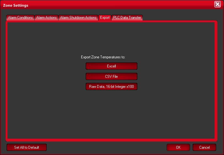
29 29 Once you have placed Zones on the image display, detailed management of the Zones in place can be accomplished using the Properties button found at the bottom of each active Zone panel. Once this button has been depressed a dialog worksheet will appear by which this management will be carried out. There are two main features that can be set from within this dialog; Alarm Setting and Export control 8.2: Alarms The Alarms configuration for each Zone allows you to set up the system to continuously monitor the analysis points discussed for the Zones and alarm if any of the Zones' average temperature value exceed the temperature limits specified by you within this worksheet. 8.3: Export Export allows you to export the data within a Zone in three different formats as shown in the graphic below. This dialog box is invoked through the Zone Properties button found in each Zone interface box.
30 30
31 31 Section 9: Radiometry 9.1: Introduction Typically the very basic reason for employing image processing programs when analyzing IR images is to have an easy and fast, yet comprehensive means to determine the information content of an image in numerical terms. Radiometry is considered the "BASE" from which to conduct this analysis. Typically, to convert the gray scale values to values of temperatures requires either a calibration of individual cameras, cameras that provide reference parameters using internal black-bodies, or by using field "ground truth" calibration data. The method for calibrating images provided in this program is camera dependent because temperature calibration data is provided by an advanced calibration process at the factory and installed in this software program. This program looks for a very specific file in its structure and mates that with the camera serial number automatically read by the program. If this software cannot match the camera to the calibration file, the user cannot perform temperature analysis on the data. If your specific package includes additional optional lenses a separate calibration is required for each lens. See the Camera Menu chapter for selecting the lens you are currently using.

32 32 9.2: Radiometric Correction Note that accuracy of temperature conversion is typically more dependent on the physics of the scene than on the detailed calibration/temperature model provided with the software. These physical properties include emissivity and reflection of the target, the transmission in the intervening atmosphere, and the background/foreground temperature within the scene. The work sheet shown below allows the user the ability to offset some of this error by defining these parameters as accurately as practical. Enter the Target Emissivity: You are provided the capability to select any value of surface optical property of the target surface you deem appropriate to the analysis being performed. Simply move the cursor to the Target Emissivity field and click the mouse button. Once done enter the value from 1.0 to Transmission: This value is the percentage of energy loss due the transmission of the energy from the target surface to the camera. This loss can be a result of any intervening medium such as atmosphere, IR windows, etc. This loss is entered as a percentage value for 1.0 to Ambient Temperature: The Ambient Temperature, which is often referred to as the Background, is the temperature of the surfaces surrounding the imaged object. These surfaces are those whose energy will hit the face of the imaged object and reflect from it into the camera FOV. Note: As the value of emissivity becomes lower the error between the actual surface temperature of the object and that shown by the camera becomes greater. A great deal of error can be introduced into the calculation process if you are not careful with the emissivity specification.

33 33 Section 10: Camera Menu Choice 10.1: Introduction The Camera Menu Choice is found on the fifth selection of the Main Menu Bar. This selection provides features that allow you control over the actual operation of the camera. There are three sub-menu choices found within this selection. 10.2: Camera Menu Choice: Image Touch-Up The Image Touch-Up function performs a Non-Uniformity Correction (NUC), setting all pixels in the camera to the same average reading. In the 7000 series cameras (7320 and 7640), the camera needs to either have its lens cap placed back on or it needs to be looking at a surface with a consistent temperature (often, placing it looking down on a table to other solid surface). For the 9000 series cameras (9320 and 9640), there is an internal shutter that will automatically perform a NUC every three minutes; selecting the Image Touch-Up option manually triggers the shutter instead. 10.3: Camera Menu Choice: Delete Touch-Up Data The Touch-Up function saves the Touch-Up data in a file and will be used at subsequent boot-up of the camera. This data file can be deleted by simply selecting the Delete Touch-Up sub-menu choice.
34 : Camera Menu Choice: Reset Camera If for any reason the computer s USB port is disrupted at any time and proper communication with the camera is disturbed, hit the Camera Reset sub-menu choice and the camera will reboot and reestablish USB communication, providing the USB port on the computer is functioning properly. 10.5: Camera Menu Choice: Lens Choice Some models such as the 7000 series cameras (7320 and 7640) do offer multiple lenses; multiple calibration files are saved and selecting the appropriate lens option causes IR Flash to adjust accordingly. At this time, though, the 9000 series cameras (9320 and 640) do not.
FLIR Tools for PC 7/21/2016
 FLIR Tools for PC 7/21/2016 1 2 Tools+ is an upgrade that adds the ability to create Microsoft Word templates and reports, create radiometric panorama images, and record sequences from compatible USB and
Help. Appendix A Camera Settings. IncuCount
 Help The help menu has three items: About - will give company name and model information User Guide - will open up this document. Contact information - for Revolutionary Science's Technical support. Email:
Sense. 3D Scanner. User Guide. See inside for use and safety information.
 Sense 3D Scanner User Guide See inside for use and safety information. 1 CONTENTS INTRODUCTION.... 3 IMPORTANT SAFETY INFORMATION... 4 Safety Guidelines....4 SENSE 3D SCANNER FEATURES AND PROPERTIES....
Release date: 17 th of September, 2017 End users Validity date: 31 st of December, 2018 or till next revision Revision Number: 2.9
 Release date: 17 th of September, 2017 End users Validity date: 31 st of December, 2018 or till next revision Revision Number: 2.9 Workswell Infrared Cameras Introduction Workswell Infrared Cameras ( WIC
Instruction Manual for the Revolutionary Science RS-IC-150 IncuCount
 Instruction Manual for the Revolutionary Science RS-IC-150 IncuCount REVO LUTIONA RY SCIENCE Making Science Simple! Table of Contents Introduction 2 Parts Checklist, Notes, Service Record 3 Warranty 4
SKF TKTI. Thermal Camera Software. Instructions for use
 SKF TKTI Thermal Camera Software Instructions for use Table of contents 1. Introduction...4 1.1 Installing and starting the Software... 5 2. Usage Notes...6 3. Image Properties...7 3.1 Loading images
MedRx Avant Polar HIT AH-I-MPHITS-5 Effective 11/07/11
 INSTALLATION MANUAL 2 Contents Getting To Know Your AVANT POLAR HIT TM... 4 Setting up the System... 6 Software Installation... 7 Driver Installation Windows 7... 10 Driver Installation Windows XP... 13
Arcturus XT Laser Capture Microdissection System AutoScanXT Software Module. User Manual
 Arcturus XT Laser Capture Microdissection System AutoScanXT Software Module User Manual For Research Use Only. Not intended for any animal or human therapeutic or diagnostic use. Information in this document
SPM-50 RF Spectrum Power Meter PC Software User Manual
 SPM-50 RF Spectrum Power Meter PC Software User Manual Shineway Technologies, Inc. Notices Copyright 2014, ShinewayTech, All rights reserved. No part of this manual may be reproduced in any form or by
AgilEye Manual Version 2.0 February 28, 2007
 AgilEye Manual Version 2.0 February 28, 2007 1717 Louisiana NE Suite 202 Albuquerque, NM 87110 (505) 268-4742 support@agiloptics.com 2 (505) 268-4742 v. 2.0 February 07, 2007 3 Introduction AgilEye Wavefront
KoPa Scanner. User's Manual A99. Ver 1.0. SHENZHEN OSTEC OPTO-ELECTRONIC TECHNOLOGY CO.,LTD.
 KoPa Scanner A99 User's Manual Ver 1.0 SHENZHEN OSTEC OPTO-ELECTRONIC TECHNOLOGY CO.,LTD. http://www.ostec.com.cn Content Chapter 1 Start... 1 1.1 Safety Warnings and Precautions... 1 1.2 Installation
EAN-Blending. PN: EAN-Blending 11/30/2017. SightLine Applications, Inc.
 PN: EAN-Blending 11/30/2017 SightLine Applications, Inc. Contact: Web: sightlineapplications.com Sales: sales@sightlineapplications.com Support: support@sightlineapplications.com Phone: +1 (541) 716-5137
Non-contact Forehead IR Thermometer
 User s Manual 99 Washington Street Melrose, MA 02176 Phone 781-665-1400 Toll Free 1-800-517-8431 Visit us at www.testequipmentdepot.com Non-contact Forehead IR Thermometer Model IR200 Introduction Congratulations
eflex 75x/300x Digital Microscope with Flexible Neck User Guide
 eflex 75x/300x Digital Microscope with Flexible Neck User Guide Table of Contents Important information... 4 Product description... 4 Computer requirements... 5 Windows based PC... 5 Mac OS based PC...
Chlorophyll Fluorescence Imaging System
 Quick Start Guide Chlorophyll Fluorescence Imaging System Quick Start Guide for Technologica FluorImager software for use with Technlogica CFImager hardware Copyright 2006 2015 TECHNOLOGICA LIMITED. All
SensorTrace BASIC 3.0 user manual
 SensorTrace BASIC 3.0 user manual 3 Se n s o rtr a c e BASIC 3.0 Us e r Ma n u a l Copyright 2010 Unisense A/S Version October 2010 SensorTrace basic 3.0 User manual Unisense A/S TABLE OF CONTENTS Congratulations
1.3. User s manual FLIR Report Studio
 1.3 User s manual FLIR Report Studio User s manual FLIR Report Studio #T810197; r. AD/44253/45486; en-us iii Table of contents 1 Legal disclaimer...1 1.1 Legal disclaimer...1 1.2 Usage statistics...1 1.3
Universal Camera Registration User Guide for ILS 9.75 & 12.75
 User Guide for ILS 9.75 & 12.75 www.ulsinc.com Overview Camera Registration allows the laser system to automate the alignment of a vector path with the material for the purpose of tightening process control
User Manual. Copyright 2010 Lumos. All rights reserved
 User Manual The contents of this document may not be copied nor duplicated in any form, in whole or in part, without prior written consent from Lumos. Lumos makes no warranties as to the accuracy of the
4.5.1 Mirroring Gain/Offset Registers GPIO CMV Snapshot Control... 14
 Thank you for choosing the MityCAM-C8000 from Critical Link. The MityCAM-C8000 MityViewer Quick Start Guide will guide you through the software installation process and the steps to acquire your first
1. What is SENSE Batch
 1. What is SENSE Batch 1.1. Introduction SENSE Batch is processing software for thermal images and sequences. It is a modern software which automates repetitive tasks with thermal images. The most important
Model OI-6940 Notis Quad 4-Gas Sensor Assembly
 Model OI-6940 Notis Quad 4-Gas Sensor Assembly Operation Manual Revision 2.3w Product Overview The Otis Instruments, Inc. Gen II WireFree OI-6940 Notis Quad is a battery-powered explosion-proof 4-gas sensor
Quick Start Guide for the PULSE PROFILING APPLICATION
 Quick Start Guide for the PULSE PROFILING APPLICATION MODEL LB480A Revision: Preliminary 02/05/09 1 1. Introduction This document provides information to install and quickly start using your PowerSensor+.
Welcome to Polaroid PhotoMAX FUN!
 Contents Welcome to Polaroid PhotoMAX FUN!...................... 1 The Polaroid PhotoMAX FUN! Digital 320 Creative Kit......... 2 Kit components......................................... 3 Polaroid Digital
FE-150/X-730 FE-160/X-735
 DIGITAL CAMERA FE-150/X-730 FE-160/X-735 Advanced Manual Detailed explanations of all the functions for getting the most out of your camera. Thank you for purchasing an Olympus digital camera. Before you
#
 INSTALLATION MANUAL 2 Contents Getting To Know Your AVANT POLAR HIT TM... 4 Setting up the System... 6 Software Installation... 7 Driver Installation Windows 7... 10 Driver Installation Windows XP... 13
Contents STARTUP MICROSCOPE CONTROLS CAMERA CONTROLS SOFTWARE CONTROLS EXPOSURE AND CONTRAST MONOCHROME IMAGE HANDLING
 Operations Guide Contents STARTUP MICROSCOPE CONTROLS CAMERA CONTROLS SOFTWARE CONTROLS EXPOSURE AND CONTRAST MONOCHROME IMAGE HANDLING Nikon Eclipse 90i Operations Guide STARTUP Startup Powering Up Fluorescence
RAZER RAIJU TOURNAMENT EDITION
 RAZER RAIJU TOURNAMENT EDITION MASTER GUIDE The Razer Raiju Tournament Edition is the first Bluetooth and wired controller to have a mobile configuration app, enabling control from remapping multi-function
FlatPack Ultrasonic Sensors
 FlatPack Ultrasonic Sensors Installation & Operation Guide May 23, 2017 The FlatPack Sensor product line listed in the introduction of this manual complies with the European Council EMC Directive 2004/108/EC
Quick Start Overview. Related Information. In addition, the sensor includes integrated Help.
 Quick Start Guide Introduction The ivu Plus TG Series sensor is used to monitor labels, parts, and packaging for type, size, orientation, shape, and location. The sensor has an integrated or remote color
Minolta Scanner Plugin
 Minolta Scanner Plugin For a list of Minolta digitizers and Geomagic software products with which this plugin is compatible, see Release Notes for Geomagic Minolta Plugin 7.6.0.3. Copyright 2005, Raindrop
The CO2 Sensor Calibration Kit
 The CO2 Sensor Kit For use with all BAPI CO 2 Sensors Instruction Manual CO 2 Kit Product Identification and Overview BAPI s CO 2 Sensor Kit is designed to calibrate and verify the operation of all BAPI
A W Table-Top Amplifier. with Built-in Bluetooth streaming
 A0361 100W Table-Top Amplifier with Built-in Bluetooth streaming 17 The A0361 Table-Top Amplifier can be used with Channel Vision s CAT5 audio hubs to provide a powerful 100 Watt Amplifier, 50Watts per
OPERATION & SERVICE MANUAL FOR FC 110 AC POWER SOURCE
 OPERATION & SERVICE MANUAL FOR FC 100 SERIES AC POWER SOURCE FC 110 AC POWER SOURCE VERSION 1.3, April 2001. copyright reserved. DWG No. FC00001 TABLE OF CONTENTS CHAPTER 1 INTRODUCTION... 1 1.1 GENERAL...
Gentec-EO USA. T-RAD-USB Users Manual. T-Rad-USB Operating Instructions /15/2010 Page 1 of 24
 Gentec-EO USA T-RAD-USB Users Manual Gentec-EO USA 5825 Jean Road Center Lake Oswego, Oregon, 97035 503-697-1870 voice 503-697-0633 fax 121-201795 11/15/2010 Page 1 of 24 System Overview Welcome to the
Aimetis Outdoor Object Tracker. 2.0 User Guide
 Aimetis Outdoor Object Tracker 0 User Guide Contents Contents Introduction...3 Installation... 4 Requirements... 4 Install Outdoor Object Tracker...4 Open Outdoor Object Tracker... 4 Add a license... 5...
GlassSpection User Guide
 i GlassSpection User Guide GlassSpection User Guide v1.1a January2011 ii Support: Support for GlassSpection is available from Pyramid Imaging. Send any questions or test images you want us to evaluate
Nikon View DX for Macintosh
 Contents Browser Software for Nikon D1 Digital Cameras Nikon View DX for Macintosh Reference Manual Overview Setting up the Camera as a Drive Mounting the Camera Camera Drive Settings Unmounting the Camera
KODAK Dental Imaging Software. Quick Start Guide
 KODAK Dental Imaging Software Quick Start Guide Notice Congratulations on your purchase of The KODAK Dental Imaging Software. Thank you for your confidence in our products and we will do all in our power
RAZER GOLIATHUS CHROMA
 RAZER GOLIATHUS CHROMA MASTER GUIDE The Razer Goliathus Chroma soft gaming mouse mat is now Powered by Razer Chroma. Featuring multi-color lighting with inter-device color synchronization, the bestselling
BANTAM INSTRUMENTS SOFTWARE USER S MANUAL MIL-STD-461E PRE-COMPLIANCE MEASUREMENT SYSTEM MODEL EMC-461. Model EMC-461 Software User s Manual
 BANTAM INSTRUMENTS MIL-STD-461E PRE-COMPLIANCE MEASUREMENT SYSTEM MODEL EMC-461 SOFTWARE USER S MANUAL MIL-STD-461E PRE-COMPLIANCE MEASUREMENT SYSTEM MODEL EMC-461 Software User s Manual BANTAM INSTRUMENTS
Product Manual. Getting Started with Roadie 2.
 MOL NUMBER RD200 Product Manual Getting Started with Roadie 2. This manual is a quick start guide for Roadie 2. Please read the following instructions and conditions before using Roadie 2. For a more comprehensive
The ideal K-12 science microscope solution. User Guide. for use with the Nova5000
 The ideal K-12 science microscope solution User Guide for use with the Nova5000 NovaScope User Guide Information in this document is subject to change without notice. 2009 Fourier Systems Ltd. All rights
ivu Plus Quick Start Guide P/N rev. A -- 10/8/2010
 P/N 154721 rev. A -- 10/8/2010 Contents Contents 1 Introduction...3 2 ivu Plus Major Features...4 2.1 Demo Mode...4 2.2 Sensor Types...4 2.2.1 Selecting a Sensor Type...5 2.3 Multiple Inspections...6 2.3.1
LD2342 USWM V1.6. LD2342 V1.4 Page 1 of 18
 LD2342 USWM V1.6 LD2342 V1.4 Page 1 of 18 GENERAL WARNINGS All Class A and Class B marine Automatic Identification System (AIS) units utilize a satellite based system such as the Global Positioning Satellite
Tribometrics. Version 2.11
 Tribometrics Version 2.11 Table of Contents Tribometrics... 1 Version 2.11... 1 1. About This Document... 4 1.1. Conventions... 4 2. Introduction... 5 2.1. Software Features... 5 2.2. Tribometrics Overview...
Zeiss AxioImager.Z2 Brightfield Protocol
 Zeiss AxioImager.Z2 Brightfield Protocol 1) System Startup Please note put sign-up policy. You must inform the facility at least 24 hours beforehand if you can t come; otherwise, you will receive a charge
Image Pro Ultra. Tel:
 Image Pro Ultra www.ysctech.com info@ysctech.com Tel: 510.226.0889 Instructions for installing YSC VIC-USB and IPU For software and manual download, please go to below links. http://ysctech.com/support/ysc_imageproultra_20111010.zip
34134A AC/DC DMM Current Probe. User s Guide. Publication number April 2009
 User s Guide Publication number 34134-90001 April 2009 For Safety information, Warranties, Regulatory information, and publishing information, see the pages at the back of this book. Copyright Agilent
LincView OPC USER GUIDE. Enhanced Diagnostics Utility INDUSTRIAL DATA COMMUNICATIONS
 USER GUIDE INDUSTRIAL DATA COMMUNICATIONS LincView OPC Enhanced Diagnostics Utility It is essential that all instructions contained in the User Guide are followed precisely to ensure proper operation of
MC3 Motion Control System Shutter Stream Quickstart
 MC3 Motion Control System Shutter Stream Quickstart Revised 7/6/2016 Carousel USA 6370 N. Irwindale Rd. Irwindale, CA 91702 www.carousel-usa.com Proprietary Information Carousel USA has proprietary rights
640SEcdqs.book Page 1 Tuesday, June 20, :40 PM FUN! FLASH 640 SE Rev. 1, June 10, 2002
 FUN! FLASH 640 SE Rev. 1, June 10, 2002 Contents The Polaroid PhotoMAX FUN! FLASH 640 SE Creative Kit......... 2 Kit components........................................ 3 Camera features........................................
How to Operate the Testo 870 thermal imager
 How to Operate the Testo 870 thermal imager Content 1. Technical data testo 870-1 & 870-2 2. Technical overview (Fixed focus) 3. Interface/internal memory 4. Inserting the battery 5. Operation of the testo
Internal B-EN Rev A. User Guide. Leaf Aptus.
 User Guide Internal 731-00399B-EN Rev A Leaf Aptus www.creo.com/leaf Copyright Copyright 2005 Creo Inc. All rights reserved. No copying, distribution, publication, modification, or incorporation of this
Enhancement of Multispectral Images and Vegetation Indices
 Enhancement of Multispectral Images and Vegetation Indices ERDAS Imagine 2016 Description: We will use ERDAS Imagine with multispectral images to learn how an image can be enhanced for better interpretation.
23070 / Digital Camera Owner s Manual
 23070 / 23072 Digital Camera Owner s Manual 2007 Sakar International, Inc. All rights reserved. 2007 Crayola Windows and the Windows logo are registered trademarks of Microsoft Corporation. All other trademarks
What is a WQSensor? Software Installation. Uninstalling WQSensors Software. NexSens Technology, Inc. TABLE OF CONTENTS
 Revision 2.01 TABLE OF CONTENTS 1 Sensor Operation... 3 1.1 ph & Temperature Sensors... 3 1.1.1 WQ-pH ph & Temperature Sensor...3 1.1.2 Making ph Sensor Measurements...4 1.1.3 Maintenance and Care...7
HP Designjet HD Scanner and T1200 HD Multifunction Printer
 HP Designjet HD Scanner and T1200 HD Multifunction Printer Introductory information USB 2.0 high-speed certified Introductory Information Other sources of information The User s Guide for your scanner
Copyright 2014 SOTA Imaging. All rights reserved. The CLIOSOFT software includes the following parts copyrighted by other parties:
 2.0 User Manual Copyright 2014 SOTA Imaging. All rights reserved. This manual and the software described herein are protected by copyright laws and international copyright treaties, as well as other intellectual
WELCOME WHAT S IN THE BOX
 WELCOME Congratulations on purchasing your Visioneer PaperPort flatbed scanner. With your scanner, you can quickly scan paper documents and color photos to place their electronic images on your computer.
X80 Activator. User's Manual. Version 1.1.
 X80 Activator User's Manual Version 1.1 www.buckeyecam.com Table of Contents 1. Warnings... 3 2. Overview... 4 3. Getting Started... 5 4. Using the Activate Button... 7 5. Wiring... 8 6. Specifications...
Instruction Manual for HyperScan Spectrometer
 August 2006 Version 1.1 Table of Contents Section Page 1 Hardware... 1 2 Mounting Procedure... 2 3 CCD Alignment... 6 4 Software... 7 5 Wiring Diagram... 19 1 HARDWARE While it is not necessary to have
OCULUS VR, LLC. Oculus User Guide Runtime Version Rev. 1
 OCULUS VR, LLC Oculus User Guide Runtime Version 0.4.0 Rev. 1 Date: July 23, 2014 2014 Oculus VR, LLC All rights reserved. Oculus VR, LLC Irvine, CA Except as otherwise permitted by Oculus VR, LLC, this
ACCU-GOLD QUICK START MANUAL
 ACCU-GOLD Now includes support for the light sensor (AGLS) and Accu Gold+ digitizers and sensors (AGDM+, AGMS DM+) Nomenclature AGDM Accu-Gold Digitizer Module RGDM Rapid-Gold Digitizer Module RGDM-MA
USER MANUAL PV 360. Vidifox Document Camera
 Vidifox Document Camera PV 360 USER MANUAL Please read this User Manual thoroughly before you use the document camera. Keep the CD-ROM in a convenient place so you can use it quickly if you need to. Please
OPERATION MANUAL MIMAKI ENGINEERING CO., LTD.
 OPERATION MANUAL MIMAKI ENGINEERING CO., LTD. http://www.mimaki.co.jp/ E-mail:traiding@mimaki.co.jp D200674 About FineCut for CorelDRAW Thank you very much for purchasing a product of Mimaki. FineCut,
Happy Link Software INSTRUCTION MANUAL
 Happy Link Software INSTRUCTION MANUAL 101001E-3 HAPPY Contents Regarding this software Normal Operation -------------------------------------------------------------------------------------------------
reference guide reference guide reference guide
 hp photosmart 240 series reference guide reference guide reference guide contents 1 welcome..................................... 1 find more information.............................. 1 what s in the box.................................
EA3012 TRANSCONDUCTANCE AMPLIFIER OPERATION MANUAL
 EA3012 TRANSCONDUCTANCE AMPLIFIER Ü EA3012 Transconductance Amplifier Operation Manual Version 2.00 Dec 2011 All product names are trademarks of their respective companies Guarantee and service Transmille
ThermaViz. Operating Manual. The Innovative Two-Wavelength Imaging Pyrometer
 ThermaViz The Innovative Two-Wavelength Imaging Pyrometer Operating Manual The integration of advanced optical diagnostics and intelligent materials processing for temperature measurement and process control.
Handbook for the SX SuperStar high resolution guide camera
 Handbook for the SX SuperStar high resolution guide camera Thank you for purchasing a Starlight Xpress SuperStar guide camera. We hope that you will be very pleased with the performance of this product.
Datasheet. Release date: 17 th of December, 2016 End users Validity date: 31 st of December, 2016 till next revision Revision Number: 1.
 Datasheet Release date: 17 th of December, 2016 End users Validity date: 31 st of December, 2016 till next revision Revision Number: 1.1 Introduction Workswell s.r.o. is pleased to introduce you a brand
FastGene FAS-V Imaging System. Catalogue Number GP-FAS-V
 FastGene FAS-V Imaging System Catalogue Number GP-FAS-V Content 1. SAFETY INFORMATION 3 2. WARRANTY 3 3. CONTACT DETAILS 3 4. REGULATORY NOTICE 4 5. IMPORTANT NOTICE 4 6. SPECIFICATION 5 7. NOMENCLATURE
ImagesPlus Basic Interface Operation
 ImagesPlus Basic Interface Operation The basic interface operation menu options are located on the File, View, Open Images, Open Operators, and Help main menus. File Menu New The New command creates a
LVTX-10 Series Ultrasonic Sensor Installation and Operation Guide
 LVTX-10 Series Ultrasonic Sensor Installation and Operation Guide M-5578/0516 M-5578/0516 Section TABLE OF CONTENTS 1 Introduction... 1 2 Quick Guide on Getting Started... 2 Mounting the LVTX-10 Series
FLIR K2. FLIR-DIRECT.ca
 Copyright All rights reserved worldwide. Names and marks appearing herein are either registered trademarks or trademarks of FLIR Systems and/or its subsidiaries. All other trademarks, trade names or company
Coordinate Planes Interactive Math Strategy Game
 Coordinate Planes Manual 1 Coordinate Planes Interactive Math Strategy Game 2016-2007 Robert A. Lovejoy Contents System Requirements... 2 Mathematical Topics... 3 How to Play... 4 Keyboard Shortcuts...
MIF ZEISS LSM510 CONFOCAL USER PROTOCOL
 MIF ZEISS LSM510 CONFOCAL USER PROTOCOL START-UP Turn on the Mercury Bulb Power Supply (if needed). Power-on the Control Box. Turn on the computer. Open the LSM 510 software. Choose Scan New Images and
ARIS B.V. ARIS CycloSearch for ArcMap User's Manual
 ARIS B.V. http://www.aris.nl/ ARIS CycloSearch for ArcMap User's Manual Table of contents 1. Introduction...3 2. Installation...4 3. Registration...5 4. Version History...6 4.1 Version 1.0...6 4.2 Version
FluorCam PAR- Absorptivity Module & NDVI Measurement
 FluorCam PAR- Absorptivity Module & NDVI Measurement Instruction Manual Please read this manual before operating this product P PSI, spol. s r. o., Drásov 470, 664 24 Drásov, Czech Republic FAX: +420 511
Digital Portable Overhead Document Camera LV-1010
 Digital Portable Overhead Document Camera LV-1010 Instruction Manual 1 Content I Product Introduction 1.1 Product appearance..3 1.2 Main functions and features of the product.3 1.3 Production specifications.4
User Guide for TWAIN / DirectX interface for GRYPHAX USB 3.0 cameras
 User Guide for TWAIN / DirectX interface for GRYPHAX USB 3.0 cameras The TWAIN & DirectX driver for PROGRES GRYPHAX USB 3.0 cameras enables user to operate with TWAIN and DirectX supported 3 rd party software
Thermography. White Paper: Understanding Infrared Camera Thermal Image Quality
 Electrophysics Resource Center: White Paper: Understanding Infrared Camera 373E Route 46, Fairfield, NJ 07004 Phone: 973-882-0211 Fax: 973-882-0997 www.electrophysics.com Understanding Infared Camera Electrophysics
Programmable K-Factor Scaler B and Programming Software Kit B
 Programmable K-Factor Scaler B220-885 and Programming Software Kit B220-900 INSTALLATION & INSTRUCTION MANUAL 8635 Washington Avenue Racine, Wisconsin 53406 Toll Free: 800.235.1638 Phone: 262.639.6770
Table of Contents 1. Image processing Measurements System Tools...10
 Introduction Table of Contents 1 An Overview of ScopeImage Advanced...2 Features:...2 Function introduction...3 1. Image processing...3 1.1 Image Import and Export...3 1.1.1 Open image file...3 1.1.2 Import
Combo Scanner. User Manual
 Combo Scanner User Manual I. Unpack the Combo Scanner Backlight Holder Combo Scanner Business card Fixture Photo/Business Card Holder User Manual Quick Installation Guide Note This Combo Scanner supports
RUSH G1 MECHANICAL KEYBOARD PRODUCT MANUAL V.14
 RUSH G1 MECHANICAL KEYBOARD V.14 SOFTWARE INSTALLATION DOWNLOAD SOFTWARE INSTALLER From: http://download.fnatic.com RUN THE INSTALLER ACCEPT POP UPS If you are prompted by any pop ups during the installation,
Principles and Practice
 Principles and Practice An Integrated Approach to Engineering Graphics and AutoCAD 2011 Randy H. Shih Oregon Institute of Technology SDC PUBLICATIONS www.sdcpublications.com Schroff Development Corporation
Page 1/10 Digilent Analog Discovery (DAD) Tutorial 6-Aug-15. Figure 2: DAD pin configuration
 Tutorial 6-Aug-15. Figure 2: DAD pin configuration") Page 1/10 Digilent Analog Discovery (DAD) Tutorial 6-Aug-15 INTRODUCTION The Diligent Analog Discovery (DAD) allows you to design and test both analog and digital circuits. It can produce, measure and
Page 1/10 Digilent Analog Discovery (DAD) Tutorial 6-Aug-15 INTRODUCTION The Diligent Analog Discovery (DAD) allows you to design and test both analog and digital circuits. It can produce, measure and
iq-led Software V2.1
 iq-led Software V2.1 User Manual 31. January 2018 Image Engineering GmbH & Co. KG Im Gleisdreieck 5 50169 Kerpen-Horrem Germany T +49 2273 99991-0 F +49 2273 99991-10 www.image-engineering.com CONTENT
Installation & User Manual Micro-Image Capture 7
 Installation & User Manual Micro-Image Capture 7 Ver1.2016 Product Warranty Quality Assurance Every Micro-Image Capture system passes quality assurance tests including focus, resolution quality and mechanical
Information & Instructions
 KEY FEATURES 1. USB 3.0 For the Fastest Transfer Rates Up to 10X faster than regular USB 2.0 connections (also USB 2.0 compatible) 2. High Resolution 4.2 MegaPixels resolution gives accurate profile measurements
Alternate Button Functions
 Model ST-122 Owner's Manual Front Panel The front panel of the ST122 is shown below. The buttons have dual functions, selected the by Alt key in the lower right. The upper diagram shows the primary functions,
Infrared Gun. Perfect For. Easy To Use. Features. Get Professional Results Every Time! Battery Installation. Model: IN1022
 Model: IN1022 Infrared Gun -76 to +1022 F/-60 to +550 C Perfect For Non-contact surface temperatures Easy To Use 1-second response Laser target illumination Backlit Data-hold One-button operation Features
LPU-2127 User Manual
 LPU-2127 User Manual Doc #9004169 Rev A1, 04/15 Table of Contents Introduction... iii Warranty and Warranty Restrictions... iv Chapter 1: Specifications and Options... 1 Dimensions...1 Specifications...
Printer Software Guide
 Printer Software Guide (For Canon Compact Photo Printer Solution Disk Version 6) Windows 1 Contents Safety Precautions...3 Read This First...4 About the Manuals...4 Printing Flow Diagram...5 Printing...6
InsideIR. Users Manual. Thermal Image Analysis Software
 InsideIR Thermal Image Analysis Software Users Manual January 2006 2006 Fluke Corporation, All rights reserved. Printed in USA. All product names are trademarks of their respective companies. Table of
SRT Marine Technology. LD2342 V1.4 Page 1 of 22
 LD2342 V1.4 Page 1 of 22 LD2342 V1.4 Page 2 of 22 2 LD2342 V1.4 Page 3 of 22 GENERAL WARNINGS All marine Automatic Identification System (AIS) units utilise a satellite based system such as the Global
SAFE USE &OPERATIONS MANUAL
 www.uvprocess.com Product information Updates on UV Process Supply products ITEM PART NO. VersaProbe standard package M007-092 (Standard package includes UV-A+B probe.) Individual UV-A Remote Probe M007-093