TRIAD TnT X-Ray Field Service/Calibration/QA Kit Model 10500AMT
|
|
|
- Avice Franklin
- 6 years ago
- Views:
Transcription

 AC adapter for use in lieu of batteries Introduction The TRIAD TnT Kit is a full-function,")

1 TRIAD TnT X-Ray Field Service/Calibration/QA Kit Model 10500AMT Model 10500AT TRIAD TnT Diagnostic Imaging Save time in setup and procedure Automatic temperature and pressure correction for faster operation in any environment Time saving scroll functionality for faster initial settings and recovery Recognizes and ignores spurious background signals Expanded range of functionality from a single instrument Very Low Dose Rate (down to 20 ngy/sec at a resolution of 1 ngy/sec) Broader range of dental unit kv and time measurement to include units with filament preheat Pulse count mode for use with single phase units with pulse count timers Easily measure small image intensifiers (6 inch and smaller) AC adapter for use in lieu of batteries Introduction The TRIAD TnT Kit is a full-function, x-ray dosimeter kit that performs fast, highly sensitive measurements in all modalities for x-ray field service, calibration, and quality assurance testing. The Model 10100AT TRIAD TnT Dosimeter Kit features the Model 35050AT Dosimeter, a technologically advanced, microprocessor-controlled, x-ray radiation dosimeter. The kit also includes ion chambers and test stand, triaxial/coaxial cable, AC adapter, HVL filter set, RS-232 interface cable with adapters, customization software, instruction manual CD and lightweight carrying case. Features Bright display direct readout in user-selected units, including R, Sv, Gy, /sec, /min, /hr, /frame, or electrical units (C or A) Image intensifier measurements at 0.1 µr and 0.1 µr/sec resolution; cine in µr/frame Expanded kvp and exposure time measurement capabilities Patented Linear Mammo Filter Pack kvp corrected based on Mammo K-Edge Filter Pack Simplified controls include auto-reset, auto-ranging, automatic offset & drift compensation, automatic power-down and automatic pressure and temperature correction Includes kvp and exposure time measurements when Model 35050AT is used with Model 35080B Optional TRIAD Toolkit for Excel for remote operation, waveform capture and calibration, includes MQSA, Rad and Fluoro templates Self-checking features include Model 35050AT battery voltage, bias voltage, ion chamber/cable leakage, and hardware/software checks Six AA alkaline batteries provide instrument power, as well as 300 V electronic ion chamber bias. Auto power-down feature extends battery life Applications The TRIAD TnT Kit is ideal for government compliance testing, troubleshooting, repair of diagnostic x-ray equipment, installation and setup of new equipment, preventative maintenance, radiographic quality assurance measurements, and measurements required for JCAHO accreditation. The TRIAD TnT Kit performs measurements for all modalities: radiographic, fluoroscopic, mammographic (MQSA), CT, cine and dental. The TRIAD TnT incorporates the latest design innovations to enhance ease of use, range of applications and save valuable time. TRIAD TnT continues the TRIAD tradition as the most accurate, widely used instrument of its kind available
2 Specifications for TRIAD TnT Dosimeter Kit (Model 10100AT) Exposure and exposure rate accuracy Basic accuracy of Model 35050AT is ± 1% of reading ± 2 range resolution steps over range of 18 to 28 C and ± 2% of reading ± 2 range resolution steps over the full operating temperature range of 0 to 50 C. 3% NIST-traceable calibration provided with each system and includes effects of Models 35050AT, 96035B and 96020C Exposure time measurement Exposure time accuracy is ± 0.1% of reading ± 0.2 msec. Maximum exposure time is 6.5 seconds and measurement resolution is 0.2 msec Nominal measurement range Ion chamber Units Effective range*** Resolution step size 15 cc R 100 µ to 20 1 µ R/sec 100 µ to 20 1 µ R/min 5 m to µ R/hr 100 m to 72 k 1 m R/frame** 2 µ to 333 m 0.02 µ Gy 1 µ to 175 m 0.01 µ Gy/sec 1 µ to 175 m 0.01 µ Gy/min 50 µ to µ Gy/hr 1 m to m Gy/frame** 0.02 µ to 2.9 m 0.2 n 150 cc R 10 µ to µ R/sec 10 µ to µ R/min 0.5 m to µ R/hr 10 m to 7.2 k 0.1 m R/frame** 0.2 µ to 33 m µ Gy 0.1 µ to 17.5 m µ Gy/sec 0.1 µ to 17.5 m µ Gy/min 5 µ to 1050 m 0.05 µ Gy/hr 0.1 m to m Gy/frame** µ to 290 µ 0.02 n 150 cc VLDR R/sec 2 µ to 2* 0.1 µ R/min 0.1 m to 120* 5 µ R/hr 2 m to 7.2 k* 0.1 m R/frame** 0.04 µ to 33 m* µ Gy/sec 0.02 µ to 17.5 m* µ Gy/min 1 µ to 1050 m* 0.05 µ Gy/hr 0.02 m to 63.0* m Gy/frame** 0.4 n to 290 µ* 0.02 n Electrical units C 1 p to 100 n 0.01 p A 1 p to 100 n 0.01 p Values for ion chambers are calculated using nominal sensitivities: 15 cc: 2.4 x 10 8 R/C 150 cc: 2.4 x 10 7 R/C *Very Low Dose Rate effective range at 5% resolution steps **At 60 frames/sec (1 to 120 frames/selectable) ***IEC effective range at 1% resolution steps Measurement modes kvp/dose/time Single shot, direct beam measurement of exposure, kvp, and time. Auto-ranging across three decade ranges. Auto reset between exposures. Display update after each exposure kvp/rate Simultaneous measurement of kvp and exposure rate Full sensitivity dose Auto-ranging across five decades of sensitive ranges. Automatic drift & offset compensation, and automatic post-exposure display hold Full sensitivity rate Measurement range covers a span from lowlevel image intensifier measurements to unattenuated direct beams. Automatic offset compensation and nonlinear filtering. Autoranging provides five decades of sensitivity ranges. Display updates once per second Very Low Dose Rate (VLDR) This mode is only for making very low dose rate measurements. Nonlinear digital filtering and autoranging provide five decades of sensitivity ranges. Display updates once per second. In this mode, automatic current offset and drift compensation is disabled. As a result, the system can display very low dose rates Power requirements Life ~30 hours with six AA alkaline batteries. Automatic power-down after user-selected period of unattended operation (5-255 minutes). An AC adapter is supplied with each 35050AT. When the AC adapter is in use, the auto power down feature is disabled, providing continuous operation. User selections for ion chamber, units, kv filter pack, temperature, pressure, and frame are stored in nonvolatile memory before automatic turnoff; eliminates manual re-selection at power-up Bias voltage supply Fixed electronic bias (~300 V). Bias voltage is removed from triaxial input connector at instrument turnoff Customization Allows user to modify contents of nonvolatile memory including ion chamber and kv filter pack conversion factors, temperature and pressure units, radiation units, and power down interval. A field customization software program is included for use with an IBM -PC or compatible Display Two-line, 20-character alphanumeric PLED (polymer LED), with 0.5 cm character height. Indicates all ion chamber/kv filter pack identification information, numerical measurement results, battery level, calibration date and other information Weight 14 lb (6.4 kg)

3 Connections Model 35080B interface Male, two lug BNC Computer interface RS-232, using RJ-45 connector. 9,600 baud 8-bit, 1 stop, no parity, xon/xoff. Enables fully-programmable operation and waveform display from a PC with optional Excel add-in. Powered when connected to computer Ion chamber input Triax, BNC. Collector and guard positivebiased relative to ion chamber body and dosimeter chassis Power 2.1 mm DC Power Jack, power input for an unregulated 9 V, 200 ma adapter with a center negative, 2.1 mm plug Optional accessories USB to RS-232 adapter (Model 38617) Accessories supplied Test stand (Model 37581) Machined stainless steel upright rod with base, ion chamber holder, and tray for HVL filters, which includes one ion chamber stem Programming kit (Model 37594) Includes customization software on CD, IBM-PC format and 6.5 ft (2 m) RS-232 interface cable with adapters for PC-type and AT-type computers Instruction manual (Model 35050ATCD) Model 10100AT TRIAD Field Service Kit Operator s Instruction Manual on CD Cable (Model 38208) 20 ft (6 m) coax/triax cable AC adapter 9 V, 200 ma, DC HVL filter set (Model 37668) Set of 12 aluminum filters for halfvalue layer measurements, which includes one 2 mm, two 1 mm, two 0.5 mm, three 0.1 mm, one 0.2 mm and three 0.05 mm Kit carrying case (Model 37500D) High density polyethylene (HDPE) plastic absorbs impact to protect contents. Custom-cut, high quality foam interiors surround and protect standard kit equipment and accessories. Dimensions 13 (w) x 18 (d) x 6 in (h) (33 x 46 x 15 cm) Diagnostic ionization chambers (Models 96035B and 96020C) Energy range 96035B: 30 to 150 kvp; 20 to 50 kvp for mammographic 96020C: 30 to 150 kvp Nominal sensitivity 96035B: 2.00 x 10 8 R/C (1.75 x 10 6 Gy/C) at 22 C and 1013 hpa 2.21 x 10 8 R/C (1.94 x 10 6 Gy/C) at 22 C and 1013 hpa. Flat response suitable for conventional diagnostic radiography and mammography 96020C: 2.08 x 10 7 R/C (1.82 x 10 5 Gy/C) at 22 C and 1013 hpa. Optimized for low-level image intensifier and cine measurements Construction 96035B: Graphite-coated acrylic, parallel-plate, air-vented 96020C: Composite graphite-filled thermoplastic; parallelplate, air-vented Volume 96035B: 15 cm 3 ; 96020C: 150 cm 3 Specifications for ma/mas Meter (Model 35035) The Model Digital ma/mas Meter is a versatile instrument that is used by x-ray service engineers, field service engineers and biomedical engineers to accurately measure mas and fluoroscopic ma accurately for diagnostic, radiographic, and fluoroscopic imaging equipment. The Digital ma/mas Meter operates with one, easily replaceable 9 volt alkaline battery, facilitating convenience and portability. Milliamp seconds (mas) Range Resolution Input impedance* 200 mas 0.1 mas 10 ohms 2000 mas 1.0 mas 1 ohm * Does not include fuse resistance. Also, does not include effect of bridge rectifier present when unit is set for AC Current (ma) Range Resolution Input impedance* 20 ma 0.01 ma 100 ohms 200 ma 0.1 ma 10 ohms 2000 ma 1 ma 1 ohm * Does not include fuse resistance. Also, does not include effect of bridge rectifier present when unit is set for AC. Signal input limits Function Range Maximum input limit ma OFF Input shorted; 2.0 A maximum (fuse protected) ma for 30 s* A for 30 s* A maximum (fuse protected) mas A for 30 s* A maximum (fuse protected) *Limit set by power dissipation rating of shunt resistors Controls 1) Power ma/mas switch, 2) Reset switch, 3) Range switch: 200 ma/mas, 2000 ma/mas and 20 ma range settings, 4) AC/DC switch Accuracy 1% of reading ± two least significant digits for all ranges Environmental Temperature range 5 to 35 C Relative humidity 0 to 80% Storage temperature - 20 to 50 C Dimensions 2 (w) x 2 (d) x 3.50 in (h) (15 x 5.0 x 8.75 cm) Weight 0.78 lb (0.35 kg) Display Liquid crystal display (LCD), 3.50 digit, 0.5 in (h) (13 mm) Input Two banana jacks Power requirements One 9 V alkaline battery with easy replacement Accessories supplied Test Lead Kit (Model CA-23)
4 Specifications for Non-Invasive kvp Divider (Model 35080B) The Model 35080B Non-Invasive kvp Divider quickly and accurately measures kv for all modalities. The unit checks both above and below table tubes and displays the results on either the Model 35050AT Dosimeter, a storage oscilloscope, or optional Excel Add-in software. The Model 35080B Non-Invasive kvp Divider is highly portable and eliminates the need for bulky and heavy high-voltage divider tanks. A patented* wide range filter pack is included with the Model 35080B Non-Invasive kvp Divider and provides accurate readings for the range of 50 to 150 kvp. Four optional filter packs are available for use with the Model 35080B Non-Invasive kvp Divider for CT, mammographic, and mobile applications. Features Non-invasive technology eliminates the hazards of high-voltage cables and the need for bulky divider tanks Optional filter packs enable testing in virtually all modalities Rh/Rh measurement capability when Model 35080B Non-Invasive kvp Divider is used with Cadmium K-Edge and Linear Mammo Filter Pack Pair Range 50 to 150 kvp, using only the wide-range radiographic filter pack (Model Number 37617). Range and versatility are extended with the use of special optional filter packs Accuracy Accuracy of ± 2% of reading in the range of 50 to 150 kvp, exclusive of linearity, filtration, and gain effects. Linearity corrections automatically applied when using Model 35080B Non-invasive kvp Divider with Model 35050AT Dosimeter Response time 150 µs (10% to 90%) Calibration Internally generated signal provides a calibration check Minimum time for valid reading 1 ms, 3-phase; one line cycle, single-phase Tube current Wide dynamic range from 4 to 3000 ma (3 phase), 2 to 1500 ma (single phase). Generator settings will vary in waveform and distance. Less than ± 1 kv effect for wide-range radiographic filter pack covering 50 to 150 kvp. Specialty filter packs may have different characteristics Environmental Temperature range 0 to 35 C Relative humidity 20 to 80% Storage temperature - 35º to 50 C Orientation Long axis of the Model 35080B Non-invasive kvp Divider oriented perpendicular to axis of x-ray tube to eliminate heel effect Power requirements One 9 V battery, 60 hours operation Battery-Check function connects battery to output terminals for voltage measurement Dimensions (w) x 3.5 (d) x 8.25 in (h) (6.0 x 9.0 x 21 cm) Weight 1.50 lb (0.68 kg) Accessories supplied Wide-Range Filter Pack (Model 37617) For 50 to 150 kvp Fitted carrying case Optional accessories CT Filter Pack (Model 33551) Provides precision measurements in the 70 kvp to 140 kvp range with an accuracy of ± 2%. Active area is just 3.8 cm x 0.48 cm, to accommodate the narrow beam of most scanners Cadmium K-Edge and Linear Mammo Filter Pack Pair (Model 37351/37355) Cadmium K-Edge Mammo Pack uses the inherent stability of the cadmium k-edge as an absolute reference for precision measurements between 27.5 and 29.5 kvp with ± 0.5 kv accuracy. Use the Linear Mammo Pack with the Cadmium K-Edge Mammo Pack for precision calibrations of ± 1.0 kv accuracy from 22 to 40 kvp Mobile Filter Pack (Model 37946) Easily and accurately measures kv on mid-frequency generators (> 1 khz) with substantial kv ripple (> 8%). Provides precision measurements in the range of 50 to 135 kvp with accuracy of ± 2% Low Range Filter Pack (Model 38237) Provides precision measurements in the 30 to 90 kvp range with an accuracy of ± 2%. For radiographic generators using tungsten target Tested. Meets applicable standards. * Patent numbers 4,843,619 and 4,916,727.

5 Specifications for Diagnostic Ion Chambers (Models 96020C and 96035B) The Models 96020C and 96035B Diagnostic Ion Chambers are vented volume, parallel-plate air ionization chambers with sidemounted BNC triaxial connectors. The Model 96020C Ion Chamber has a nominal volume of 150 cm 3 ; the Model 96035B has a nominal volume of 15 cm 3. Both ion chambers have a fully-guarded, centrallylocated collector plate that provides superior collection efficiency. The patented* Model 96035B has a dual energy range that enables both diagnostic and mammographic measurements. Diagnostic measurements are taken using one side of the chamber as the entrance window, and mammographic measurements are accomplished using the other side as the entrance window. Features Very low leakage and low noise Rugged mechanical construction These ionization chambers are supplied with triaxial BNC connectors Energy range 96020C 30 to 150 kvp 96035B 30 to 150 kvp for diagnostic measurements. 20 to 50 kvp for mammographic measurements Nominal volume 96020C 150 cm 3 ; cm diameter by 1.50 cm thick active volume 96035B 15 cm 3 ; 3.96 cm diameter by 1.22 cm thick active volume Nominal sensitivity 96020C H60: 2.08 x 10 7 R/C at 22 C and 760 mmhg. Optimized for low-level image intensifier and cine measurements 96035B L100: 2.0 x 10 8 R/C at 22 C and 760 mmhg. MV30 (PTB Mammo Point): 2.21 x 10 8 R/C at 22 C and 760 mmhg. Flat energy response suitable for conventional diagnostic radiography and mammography Leakage current < 10 fa under normal bias conditions (300 V) Collection efficiency 96020C 95% at 2,000 R/min 96035B 95% at 5,000 R/min Wall material 96020C Composite graphite-filled thermoplastic 96035B Graphite-coated acrylic (methyl-methacrylate) Window material 96020C 0.76 mm thick, graphite-coated polycarbonate 96035B Both entrance windows are made of 0.25 mm graphitecoated polycarbonate Window density 96020C 91 mg/cm B 32 mg/cm 2 Active window area 96020C 100 cm 2, centered within the chamber body 96035B Each side of the chamber has a circular active window region centered 7.1 mm further from the BNC connector than the center of the chamber body. Active window regions have an area of cm 2 Collector plate 96020C 0.8 mm thick graphite-coated acrylic plate, cm in diameter. A 2.16 cm x 2.85 cm guard region is electrically isolated from the collector area 96035B 0.25 mm thick, centrally mounted, graphite-coated, polycarbonate plate, 3.18 cm, ± 0.01 cm in diameter. A 1.27 x 0.89 cm guard region is electrically isolated from the collector area Connector Side-mounted, triaxial, two-lug BNC connector Calibration 96020C standard calibration The standard calibration is performed at H60 (NIST defined as 60 kvp, first HVL of 6.0 mm Al, homogeneity coefficient of 94) 96035B standard calibration The standard calibration is performed at one diagnostic and one mammographic beam quality. Calibration factors are normalized to 22 C and 760 mmhg Diagnostic unattenuated beam Calibration on the diagnostic side of the chamber is performed at M80 (NIST defined as 80 kvp, first HVL of 2.97 mm Al, homogeneity coefficient of 57) Mammographic beam Calibration on the mammographic side is performed at Mo/Mo28 (NIST defined as 28 kvp, first HVL of mm Al, homogeneity coefficient of 74.3) or MV30 (PTB defined as 30 kvp, first HVL of mm Al) * Patent number 5,508,
, Ion Chamber Stem, HVL Filter Tray HVL Filter Set (Model 37668) AC Adapter, 9 V, 200 ma, DC")
6 Model 10100AT Dosimeter (Model 35050AT) 15 cm 3 Ion Chamber (Model 96035B) 150 cm 3 Ion Chamber (Model 96020C) Coax/Triaxial Cable, 20 ft (6 m) (Model 38208) Programming Kit (Model 37594), includes customization software on CD, two-meter RS-232 interface cable and adapters Test Stand (Model 37581), Ion Chamber Stem, HVL Filter Tray HVL Filter Set (Model 37668) AC Adapter, 9 V, 200 ma, DC Instruction Manual (Model 35050ATCD) Kit Carrying Case (Model 37500D) Model 10500AT Components in Model 10100AT Kit, plus: Non-Invasive kvp Divider (Model 35080B) Wide-Range Filter Pack (Model 37617) (50 to 150 kvp) Optional accessories For all kits: CT Ion Chamber, 3.2 cm 3 (Model ) Ultra-High Purity HVL Attenuators (Model ), for mammo, set of 6 TRIAD Toolkit for Excel (Model 10500EXL) USB to RS-232 adapter (Model 38617) For Models 10500AT & 10500AMT kits: Mammographic Filter Pack Pair (Model 37355/37351) includes: Cadmium K-Edge Mammo Filter Pack (27.5 to 29.5 kvp) ± 0.5 kv accuracy Linear Mammo Filter Pack (22 to 40 kvp) ± 1.0 kv accuracy Note: Mammo Filter Packs are designed for molybdenum anode, beryllium window generators. Mobile Filter Pack (Model 37946) (50 to 135 kvp) ± 2% accuracy CT Filter Pack (Model 33551) (70 to 140 kvp) ± 2% accuracy Model 10500AMT Components of Model 10500AT Kit, plus: ma/mas Meter (Model 35035) Universal Test Lead Kit (Model CA-23) Model 10500AMT For more information, receive our full product catalog, or order online, contact Radiation Management Services business of Fluke Biomedical: or Fluke Biomedical. All rights reserved. TRIAD is a trademark of Fluke Corporation. IBM is a trademark of International Business Machines. Printed in USA AMT-ds rev 5 03 jun 05

7 TRIAD Toolkit for Excel Model 10500EXL Diagnostic Imaging Automatically collects measurement results and places them in an Excel worksheet Automatically captures kv waveforms and charts them in an Excel worksheet Templates are provided for QA tests on radiographic, fluoroscopic and mammographic x-ray machines Templates may be modified to perform user specific tests and generate user customized reports Introduction The TRIAD Toolkit for Excel is a complete software package for the TRIAD that includes an Excel Add-In, called TRIAD Tool and Excel templates that may be used to evaluate the performance of radiographic, mammographic, and fluoroscopic x-ray machines. The TRIAD Tool collects measured results from the Model 35050A Dosimeter and places the data in the active Excel worksheet. In addition, the TRIAD Tool may be used to acquire and graph kv waveforms from the TRIAD as well as remotely control the TRIAD Dosimeter. Reproducibility Machine Settings FS SDD kvp ma msec small 26 in 100 kvp msec mr Accuracy kv Accuracy Timer Accuracy kv % Error mas % Error kvp Set kvp [<5.00%] Pass/Fail msec Set msec [<5.00%] Pass/Fail % Fail % Pass % Pass % Pass % Pass % Pass % Pass % Pass % Pass % Pass % Pass % Fail % Pass % Fail % Pass % Pass Features Allows complete remote control of the TRIAD Automatically downloads Model 35050A Dosimeter configuration settings Compatible with Windows 95, 98, ME, NT 4.0, 2000, and Microsoft Excel 97, 2000 Avg CV [<0.000] Pass/Fail Pass Pass Pass mas Linearity Machine Settings Pass/Fail Criteria kvp SDD msec Adj. Non-Adj in 100 <0.050 <0.100 Beam Quality Machine Settings Min HVL 2.30 FS SDD Calculated 2.66 kvp ma msec HVL L 26 in 0.2 Pass/Fail Pass Set ma mr mr/mas CL Pass/Fail 25 s s Fail 100 s Pass 100 L Pass 150 L Pass 200 L Pass 300 L Pass mm Al mr Norm Exp Normalized Exposure Beam Quality mmal
8 Specifications Controls The TRIAD Tools menu provides an interface for the user to remotely control the TRIAD, select filter packs, chambers, units, retrieve kv waveforms, open templates, and change the options. A description of each control follows: Connect/Disconnect Connects or disconnects the TRIAD to the communications port. Connect instructs the TRIAD Tool to read configuration information such as the filter packs, chambers, and units Options Several options can be specified including COM port, temperature, pressure, and frame rate Measure Sets the TRIAD up for a single exposure using the selected filter pack, chamber, and unit Auto Reset Informs the TRIAD Tool to automatically reset the TRIAD for another exposure, allowing a series of exposures to be made without used intervention. At the time Auto Reset is clicked, the TRIAD will be set up for an exposure Filter Packs Selects the filter pack to use for kvp measurements Chambers Selects the ion chamber to use for exposure measurements Units Selects the unit to use for exposure measurements Download Waveform The Waveform button will be enabled after an exposure is made and before the TRIAD is setup for another exposure. When the Waveform button is pressed, a dialog box opens and the user is prompted for the start and end times for the waveform chart, allowing the user to specify any portion of the kv waveform. The default start and end times are for the complete waveform. The waveform data will then be placed in the active cell in the active workbook Help Opens the TRIAD Toolkit for Excel Instruction Manual Templates Three templates are also provided with the TRIAD Toolkit for Excel: a radiographic template, a mammographic template and a fluoroscopic template. Each template includes a help worksheet with detailed instructions for its use. The TRIAD Radiographic Template is used to perform the following radiographic tests: Reproducibility kvp accuracy Timer accuracy Linearity Beam quality The TRIAD Mammographic Template may be used to perform mammography tests required for ACR and MQSA. Measured data from the Model 35050A Dosimeter may be automatically collected in the following worksheets: kvp accuracy kvp reproducibility Beam quality Breast entrance exposure AEC reproducibility Average glandular dose Radiation output rate The TRIAD Fluoroscopic template is used to perform the following fluoroscopic tests: kvp Accuracy Beam quality Fluoro Exposure Rate These templates are easy to use and can be modified to fit the user s needs System requirements Windows 95, 98, ME, NT 4.0, 2000 Microsoft Excel 97, 2000 One serial port (COM1 through COM4) 10500EXL TRIAD Toolkit for Excel For more information, receive our full product catalog, or order online, contact Radiation Management Services business of Fluke Biomedical: or Fluke Biomedical. All rights reserved. TRIAD is a trademark of Fluke Corporation. Windows, Windows ME, Windows NT, and Microsoft are trademark of Microsoft Corporation. Printed in USA EXL-ds rev 3 02 feb 05

9 NERO max X-ray Test Device Victoreen Model 8000 Non-invasive evaluator of radiation outputs Diagnostic Imaging 100 khz sampling speed captures data from the most difficult machines 0.5 kv or 1% accuracy from 22 to 160 kv Measures kvp average, kv effective, kv peak, time, exposure or rate, ma or mas, HVL, exposure/frame, and mas/frame Displays R or Gy Excel Add-in includes MQSA, Rad, and Fluoro templates RS-232 computer interface Enhanced dental capabilities Introduction The Victoreen NERO max, Non-invasive Evaluator of Radiation Outputs, evaluates the widest range of x-ray machines on the market today. Evaluation of pulsed fluoro, cine, computed tomography (CT), portable, mammographic, dental, radiographic, fluoroscopic, low, medium, and high frequency machines is finally made possible with a single instrument. This fifth generation instrument features 100 khz sampling speed and direct ma/mas measurements. The NERO max s innovative Easy Flow Menu (EFM) system and flexible softkeys provide an intuitive, user friendly operating environment for quick, accurate, and easy measurements. All measurement modes and functions are displayed on the NERO max s super bright LCD and are controlled by the five softkeys directly below the display and three hard keys to the right. Seven user selectable measurement modes and three system control modes are available and clearly displayed on the control console screen for easy access and selection. Applications The NERO max consists of the control console, detector, detector cable, two filter cards, mas leads, Excel Add-in, AC adapter, HVL plates, instruction manual, and carrying case. The compact control console houses the rechargeable battery, super bright easy to read backlit display, eight control buttons, and the sophisticated electronics necessary for accurate, reproducible measurements. Connectors for power input, RS-232, printer, scope output and the NERO max detector are located on the control console s rear panel. The NERO max detector contains sensors for simultaneously measuring kv, exposure or rate and ma or mas. Solid state detectors are used to measure kv. An ion chamber, located in the top of the detector, is used for exposure/rate measurements. Connectors for external ion chambers and the NERO max detector interface are located on the rear panel of the detector. The front panel has a keyed opening for the NERO max filter cards and a connector for mas leads. The filter cards contain the various filters needed to accurately measure kilovoltage. Each filter card is coded so that the NERO max knows which filter is in use and its position. The NERO max also verifies that the filter card is valid for the selected measurement mode. The two filter cards are keyed so that they may only be inserted properly. The W/Al filter card and the Mammo filter card are clearly labeled as to the x-ray tube targets for which they are calibrated. External chambers External ion chambers for CT, mammographic, image intensifier tube, and special radiographic applications are available. Chamber calibration factors can be stored in the NERO max for direct readout of measurements. The Excel Add-in acquires measured data and waveforms directly into an Excel spread sheet to maximize flexibility for report generation


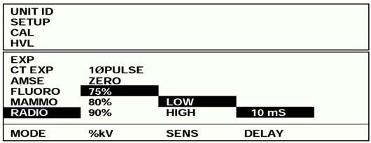
10 Real-time CT Easy Flow menu, Mode Select screen Easy Flow menu, Radio screen High frequency mammography Easy Flow menu, Mammo screen Easy Flow menu, Pulsed Fluoro display Easy Flow menu, AMSE screen Pulsed fluoro/amse Easy Flow menu, CT EXP screen Easy Flow menu, EXP screen Easy Flow menu, HVL screen
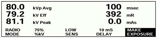
11 NERO max operating modes Radio mode Radio mode is used to make measurements on tungsten target, aluminum filtered radiographic x-ray generators Selections are available for % kv peak for the type of generator being tested. For example, Zero Crossing, Single Phase Pulse, 75%, 80%, or 90% of kvp modes are available for accurate exposure measurements on difficult x-ray machines Radio mode simultaneously measures: kvp Avg exposure kv Eff exposure time kv Peak mas Mammo mode Mammo mode is used to make measurements on mammographic x-ray generators Mammo mode simultaneously measures: kvp Avg exposure kv Eff exposure time kv Peak mas Fluoro mode Fluoro mode is used to make measurements on fluoroscopic x-ray generators. Fluoro mode supports both continuous fluoro and pulsed fluoro measurements In the continuous fluoro mode, the NERO max measures: kvp Avg exposure rate (R/min) kv Eff ma kv Peak In the pulsed fluoro mode, the NERO max measures: kvp Avg exposure rate (R/min and mr/pulse) kv Eff mas/pulse kv Peak AMSE mode AMSE mode is used for Automated Measurement of Sequential Exposures. This mode is used to measure the output of CINE generators In AMSE mode, the NERO max measures: kvp Avg exposure rate (mr/frame) kv Eff mas/frame kv Peak time/frame (ms/frame) CT Exposure mode CT Exposure mode is used to make CT exposure measurements using the Victoreen Model CT ion chamber. The CT probe must be connected to the NERO max detector s external ion chamber input in this mode Exposure mode Exposure mode is used to make exposure and rate measurements using the NERO max s internal ion chamber or an external ion chamber HVL mode In the HVL mode, the NERO max calculates half value layer based upon a series of exposure or rate measurements made with varying thicknesses of aluminum absorbers placed in the x-ray beam. A minimum of two exposures are required and up to ten exposures may be used Calibrate mode Calibrate mode is used to enter and store calibration factors for ion chambers used with the NERO max Setup mode Setup mode is used to setup various features of the NERO max. From the setup screen the user can set the instrument s parameters such as the real time clock, temperature and pressure Unit ID Displays the NERO max s serial number, firmware part number and level
12 Specifications Kilovoltage Measured during the first 480 ms of exposure Measured quantity kvp Avg, kv Eff, kv Peak Accuracy 0.5 kv or ± 1% Reproducibility 0.5 kv or ± 1% Range Target/Filter Range Filtration W/Al kv kv kv 1.2 mm of Al Mo/Mo kv 30 µ of Mo Mo/Rh kv 25 µ of Rh Mo/Al kv 1 mm of Al Rh/Rh kv 25 µ of Rh Rh/Al kv 1 mm of Al All calibrations performed with NIST traceable calibration beam. Analyze/Display cycle time Radio & mammo 3 seconds for 0.1 second exposure, 1 second for each 32 ms of exposure time Fluoro & AMSE 15 seconds for all exposures Time Radio mode Measured during entire exposure at 90, 80, 75% rise/fall of waveform, zero crossing, or pulse count Mammo mode Measured during entire exposure at 90% rise/fall of waveform Accuracy 1 ms Resolution 0.1 ms Range All diagnostic exposures from 1 ms to 60 seconds Exposure & rate Measured during entire exposure with automatic energy, temperature, and pressure correction Measured quantity Roentgens or Grays Accuracy ± 5% Reproducibility Radio and mammo modes: ± 2% or 2 mr Resolution 0.1 mr Range All diagnostic exposure and rate measurements from 1 mr to 9999 R Fluoro rate 0.1 R/min to 999 R/min mas and ma Measured invasively during entire exposure Accuracy 2% Reproducibility ± 1% or 0.2 mas Range 0.1 mas to 9999 mas, 0 to 1000 ma HVL Accuracy ± 5% Range 0.1 to 99.9 mmal Physical Display Super bright 240 x 60 pixel, super twist LCD with cold cathode fluorescent backlight Detectors Ion chamber and solid state (kv detectors) Ion chamber volume 45 cc nominal Window area/density 38 mg/cm 2 Polycarbonate HVL set 2.30 mm, 1.0 mm, 0.3 mm Al Power requirements 12 VDC 1 A external supply. Rechargeable internal batteries supply more than 4 hours of continuous service with overnight charge Physical (cont) Size Volume is 3960 in 3 (0.065 m 3 ) Console 9.00 x 9.12 x 3.25 in (22.86 x x 8.26 cm) Detector 6.56 x 3.70 x 2.58 in (16.66 x 9.4 x 6.55 cm) Filter cards 2.4 x 6.25 x 0.31 in (6.1 x x 0.8 cm) Weight Shipping 23 lb (10.43 kg) Console 4.56 lb (2.067 kg) Detector (with card) 1.65 lb (0.747 kg) Filter cards 2.9 and 3.2 oz (0.090 and kg) External chamber accessories Radiographic Ion Chamber, 30 cm 3 (Victoreen Model ): energy response: within 7% from 30 to 150 kvp (15 to 65 kev); cable: 15 ft (4.5 m); chamber dimensions: 4 x 4 x 0.54 in thick (10.2 x 10.2 x 1.4 cm) Mammographic Ion Chamber, 3.3 cm 3 (Victoreen Model ): energy response: within 5% from 0.2 to 5.0 mm Al HVL (16 to 90 kvp); cable: 15 ft (4.5 m); chamber dimensions: 4 cm Ø x 1.5 cm thick. This chamber meets the needs of the MQSA for an external transparent chamber. Option: Probe Holder (Model ) for BRH2 test stand Image Intensifier Ion Chamber, 150 cm 3 (Victoreen Model B): energy response: ± 10% from 1.8 to 10 mm Al HVL; cable: 10 ft (3.0 m); chamber dimensions: 6.26 x 8 x 0.63 in (15.9 x 20.6 x 1.6 cm) Scatter Ion Chamber, 400 cm 3 (Victoreen Model B): energy response: ± 5% from 32 to 662 kev; cable 10 ft (3.0 m); chamber dimensions: 6.26 x 8 x 0.63 in (15.9 x 20.6 x 1.6 cm) CT Ion Chamber, 3.2 cm 3 (Victoreen Models and ): energy response: ± 5% from 1 to 10 mm Al HVL; cable: 3 ft (0.9 m); sensitive length: 4 in (10.0 cm); chamber inside Ø: 0.25 in (6.4 mm) CT High Sensitivity Ion Chamber, 10 cm 3, for multislice CT (Victoreen Models and ): energy response: ± 5% from 1 to 10 mm Al HVL; cable: 3 ft (0.9 m); sensitive length: 4 in (10.0 cm); chamber inside Ø: 0.45 in (11.44 mm) Optional accessories Ultra-High Purity HVL Attenuators (Model ): for mammo, set of NERO max X-Ray Test Device, consists of a control console, detector, detector cable, two filter cards, mas leads, Excel Add-in, HVL plates, instruction manual, and carrying case Available AC adapters (specify with order) Model Description Typical geo. region VAC 12 VDC 1000 ma USA, Japan VAC 12 VDC 1000 ma Europe VAC 12 VDC 1000 ma UK and adapter 230 VAC 12 VDC 1000 ma Australia Tested. Meets applicable standards. For more information, receive our full product catalog, or order online, contact Radiation Management Services business of Fluke Biomedical: or Fluke Biomedical. All rights reserved. Victoreen and NERO are trademarks of Fluke Corporation. Printed in USA ds rev 4 12 may 05
13 NERO Victoreen max Toolkit for Excel Model 8000mAx Diagnostic Imaging Automatically collects measurement results and places them in an Excel worksheet Automatically captures kv waveforms and charts them in an Excel worksheet Templates are provided for QA tests on radiographic, fluoroscopic, and mammographic x-ray machines Templates may be modified to perform user specific tests and generate user customized reports Allows complete remote control of the NERO max Site: MECAL PHYSICIST'S MAMMOGRAPHY QC TEST SUMMARY Preliminary Results Room ID: Survey Date: X-Ray Unit Manufacturer: Model: Medical Physicist's QC Tests ACR Guides (Pass/Fail) MQSA Regs (Pass/Fail) 1. Mammographic Unit Assembly Evaluation Pass Pass 2. Collimation Assessment Pass Pass 3. Evaluation of Focal Spot Performance Pass Pass 4. Automatic Exposure Control (AEC) System Performance Pass Fail 5. Uniformity of Screen Speed Fail Fail 6. Artifact Evaluation Pass Pass 7. Phantom Image Quality Evaluation** Pass Pass 8. kvp Accuracy and Reproducibility Pass Pass 9. Beam Quality (Half-Value Layer) Assessment Pass Pass 10. Breast Entrance Exposure, Average Glandular Dose** Pass Pass AEC Reproducibility, and Pass Pass Radiation Output Rate Pass Pass 11. Viewbox Luminance and Room Illuminance Pass N/A **If any of the starred MQSA tests fail (Phantom Image Quality and Average Glandular Dose), corrective action must be taken before any further exams are performed. Failure of any other MQSA-mandated tests requires corrective action within 30 days of the test date. Recommended Corrective Action: Evaluation of Site's Technologist QC Program 1. Darkroom cleanliness (daily) 2. Processor QC - performed, records maintained, action taken when needed (daily) 3. Screen cleaning (weekly) 4. Mammo phantom imaging - performed, records maintained, action taken as needed (weekly) 5. Darkroom fog (semiannually) 6. Film-screen contact test (semiannually) 7. Compression pressure monitored (semiannually) 8. Repeat analysis - performed, records maintained, reviewed by radiologist (quarterly) 9. Viewboxes and viewing conditions (weekly) 10. Analysis of fixer retention (quarterly) 11. Visual checklist (monthly) Specific Comments: ACR Guides (Pass/Fail) MQSA Regs (Pass/Fail) Complete on-line help speeds learning Compatible with Windows 95, 98, ME, NT 4.0, 2000, and Microsoft Excel 97, 2000 Introduction The Victoreen NERO max Toolkit for Excel is a complete software package for the NERO max that includes an Excel Add-In, called NERO max Add-In and Excel templates that may be used to evaluate the performance of radiographic, mammographic and fluoroscopic x-ray machines. The NERO max Add-In collects measured results from the NERO max and places the data in the cells of the active Excel worksheet, starting at the active worksheet cell. The NERO max Add-In also may be used to acquire and graph radiation and kv waveforms from the NERO max as well as remotely control the NERO max. Signature Physicist's Name Phone Number This is only a preliminary list of findings. A full and final report will be mailed to you shortly. Please call me if you have any questions about this summary
14 Specifications Controls The NERO max menu provides an interface for the user to remotely control the NERO max and retrieve radiation and kv waveforms. A description of each menu option follows: Select Mode Selects the NERO max measurement mode. This allows the user to select the correct measurement mode for the template in use. For instance, the radio mode is selected when using the radiographic template, the mammo mode is selected when using the mammographic template and the fluoro mode is selected when using the fluoroscopic template Retrieve Rad Waveform Retrieves the radiation waveforms from the NERO max. When this is selected, a dialog box opens and the user may select either all of the waveform or a portion of the waveform to be charted. If a portion of the waveform is desired, the user prompted for start and end times (in milliseconds) of the waveform window Retrieve kv Waveform Retrieves the kv waveform from the NERO max. When this is selected, a dialog box opens and the user may select either all of the waveform or a portion of the waveform to be charted. If a portion of the waveform is desired, the user prompted for start and end times (in milliseconds) of the waveform window Select Com Port Allows the user to choose serial communication port COM1 COM4 for Model 8000 NERO max connection Templates Three templates are also provided with the NERO max Toolkit for Excel: a radiographic template, a mammographic template and a fluoroscopic template. Each template includes a help worksheet with detailed instructions for its use. The NERO max Radiographic Template is used to perform the following radiographic tests: Reproducibility kvp accuracy Timer accuracy Linearity Beam quality The NERO max Mammographic Template may be used to perform mammography tests required for ACR and MQSA. Measured data from the Model 8000 NERO max may be automatically collected in the following worksheets: kvp accuracy kvp reproducibility Beam quality Breast entrance exposure AEC reproducibility Average glandular dose Radiation output rate The NERO max Fluoroscopic template is used to perform the following fluoroscopic tests: kvp accuracy Beam quality Fluoro exposure rate These templates are easy to use and can be modified to fit the user s needs System requirements Windows 95, 98, ME, NT 4.0, 2000 Microsoft Excel 97, 2000 One serial port (COM1 through COM4) 8000mAx NERO max Toolkit for Excel For more information, receive our full product catalog, or order online, contact Radiation Management Services business of Fluke Biomedical: or Fluke Biomedical. All rights reserved. Victoreen and NERO are trademarks of Fluke Corporation. Windows, Windows ME, Windows NT, and Microsoft are trademarks of Microsoft Corporation. Printed in USA. 8000max-ds rev 5 03 feb 05

15 X-Ray Test Device Victoreen Model 4000M+ Diagnostic Imaging Measures kvp maximum, kvp average, kvp effective, dose and time in one exposure Compact, lightweight design Displays R or Gy External ion chambers for Mammo, CT, image intensifier and phototiming measurements Automatic exposure reset for handsoff operation Rechargeable Ni-Cd batteries provide more than six hours of continuous service RS-232 computer interface Storage scope output for real-time waveform display Reversible display for fluoro measurements Introduction The Victoreen X-Ray Test Device, Model 4000M+ does it all. Simply place the instrument in the x-ray beam, make one exposure, and it serially displays kvp Maximum, kvp Average, kvp Effective, dose, and time. The Model 4000M+ then automatically resets for the next exposure. A CsI photodiode pair provide the kvp measurements through five user-selectable filter pairs. This ensures optimum accuracy over the entire diagnostic range with minimum filtration dependence. Exposure measurements are made with a parallel plate ionization chamber located above the filter wheel. Exposure time is measured with quartz crystal accuracy. Plus, a variety of external ion chambers may be connected for even greater flexibility. Specifications Kilovoltage Accuracy 1 kv Mo/Mo (22 to 35 kvp) (Mammo generators w/30 µ Mo) Range W/Al Tubes: 27 to 155 kvp Mo/Mo Tubes: 21 to 50 kvp Time Measured during entire exposure at 90% rise/fall of waveform Accuracy Within 2% or 2 ms, whichever is greater Range 1 ms to 10 seconds Exposure Measured during entire exposure; kvp corrected Accuracy ± 5% Range 10 mr to 10 R Fluoroscopic rate Measured over one second intervals during fluoro exposure Accuracy ± 5% Range 0.5 to 200 R/min Detectors kv CsI/photodiode pair measures x-ray transmission through differential attenuators Time Computed from kv waveform stored in memory against quartz crystal time base Exposure Parallel plate ionization chamber Volume 36 cm 3 Window 38 mg/cm 2, 18.9 cm 2 polycarbonate Calibration Reference to a NIST traceable voltage divider and a calibrated exposure monitor during irradiation See next page for more specifications
16 Specifications (cont) Physical Display 16 character dot-matrix LCD Controls Model Five rocker switches On/Off Power switch Radio/Fluoro Select radiographic or fluoro operation High/Low Select for sensitivity Roll Roll thru data Exposure/All Select exposure only for external ion chamber Mo/Mo or W/Al Select anode/filter of x-ray tube Connectors Power 9 VDC, 500 ma Scope BNC for oscilloscope connection RS-232 DB-9 connector configured as DCE. BNC and banana plug for external Ion chamber Power requirements 9 VDC 500 ma external supply. Rechargeable internal Ni-Cd batteries supply more than six hours of continuous service with overnight charge Dimensions 8.5 (w) x 9 (d) x 3 in (h) (21.5 x 23 x 7.6 cm) Weight Approximately 3.5 lb (1.59 kg) HVL set Aluminum filters: 2.3, 1.0, and 0.3 mm External chamber accessories Radiographic Ion Chamber, 30 cm 3 (Victoreen Model ): energy response: within 7% from 30 to 150 kvp (15 to 65 kev); cable: 15 ft (4.5 m); chamber dimensions: 4 x 4 x 0.54 in thick (10.2 x 10.2 x 1.4 cm) Mammographic Ion Chamber, 3.3 cm 3 (Victoreen Model ): energy response: within 5% from 0.2 to 5.0 mm Al HVL (16 to 90 kvp); cable: 15 ft (4.5 m); chamber dimensions: 4 cm Ø x 1.5 cm thick. This chamber meets the needs of the MQSA for an external transparent chamber. Option: Probe Holder (Model ) for BRH2 test stand Image Intensifier Ion Chamber, 150 cm 3 (Victoreen Model B): energy response: ± 10% from 1.8 to 10 mm Al HVL; cable: 10 ft (3.0 m); chamber dimensions: 6.26 x 8 x 0.63 in (15.9 x 20.6 x 1.6 cm) Scatter Ion Chamber, 400 cm 3 (Victoreen Model B): energy response: ± 5% from 32 to 662 kev; cable 10 ft (3.0 m); chamber dimensions: 6.26 x 8 x 0.63 in (15.9 x 20.6 x 1.6 cm) CT Ion Chamber, 3.2 cm 3 (Victoreen Models and ): energy response: ± 5% from 1 to 10 mm Al HVL; cable: 3 ft (0.9 m); sensitive length: 4 in (10.0 cm); chamber inside Ø: 0.25 in (6.4 mm) CT High Sensitivity Ion Chamber, 10 cm 3, for multislice CT (Victoreen Models and ): energy response: ± 5% from 1 to 10 mm Al HVL; cable: 3 ft (0.9 m); sensitive length: 4 in (10.0 cm); chamber inside Ø: 0.45 in (11.44 mm) Optional accessories 4000 Toolkit for Excel (Model 4000EXL) Ultra-High Purity HVL Attenuators (Model ): for mammo, set of 6 Carrying Case (Model ) RS-232 Cable (Model ) 25 ft (7.6 m), 9-pin to 9-pin 4000M+ X-Ray Test Device Available AC adapters (specify with order) Model Description Typical geo. region VAC 9 VDC 500 ma USA, Japan VAC 9 VDC 500 ma Europe VAC 9 VDC 500 ma UK and adapter 230 VAC 9 VDC 500 ma Australia Tested. Meets applicable standards. For more information, receive our full product catalog, or order online, contact Radiation Management Services business of Fluke Biomedical: or Fluke Biomedical. All rights reserved. Victoreen is a trademark of Fluke Corporation. Printed in USA ds rev 3 16 may 05

17 4000 Toolkit for Excel Victoreen Model 4000EXL Diagnostic Imaging Automatically collects measurement results and places them in an Excel worksheet Captures radiation and kv waveforms and charts them in an Excel worksheet Templates are provided for QA tests on radiographic, fluoroscopic, and mammographic x-ray machines Templates may be modified to perform user specific tests and generate user customized reports Allows complete remote control of the Model 4000M+ NERO Complete on-line help speeds learning Site: MECAL PHYSICIST'S MAMMOGRAPHY QC TEST SUMMARY Preliminary Results Room ID: Survey Date: X-Ray Unit Manufacturer: Model: Medical Physicist's QC Tests ACR Guides (Pass/Fail) MQSA Regs (Pass/Fail) 1. Mammographic Unit Assembly Evaluation Pass Pass 2. Collimation Assessment Pass Pass 3. Evaluation of Focal Spot Performance Pass Pass 4. Automatic Exposure Control (AEC) System Performance Pass Fail 5. Uniformity of Screen Speed Fail Fail 6. Artifact Evaluation Pass Pass 7. Phantom Image Quality Evaluation** Pass Pass 8. kvp Accuracy and Reproducibility Pass Pass 9. Beam Quality (Half-Value Layer) Assessment Pass Pass 10. Breast Entrance Exposure, Average Glandular Dose** Pass Pass AEC Reproducibility, and Pass Pass Radiation Output Rate Pass Pass 11. Viewbox Luminance and Room Illuminance Pass N/A **If any of the starred MQSA tests fail (Phantom Image Quality and Average Glandular Dose), corrective action must be taken before any further exams are performed. Failure of any other MQSA-mandated tests requires corrective action within 30 days of the test date. Recommended Corrective Action: Evaluation of Site's Technologist QC Program 1. Darkroom cleanliness (daily) 2. Processor QC - performed, records maintained, action taken when needed (daily) 3. Screen cleaning (weekly) 4. Mammo phantom imaging - performed, records maintained, action taken as needed (weekly) 5. Darkroom fog (semiannually) 6. Film-screen contact test (semiannually) 7. Compression pressure monitored (semiannually) 8. Repeat analysis - performed, records maintained, reviewed by radiologist (quarterly) 9. Viewboxes and viewing conditions (weekly) 10. Analysis of fixer retention (quarterly) 11. Visual checklist (monthly) Specific Comments: ACR Guides (Pass/Fail) MQSA Regs (Pass/Fail) Compatible with Windows 95, 98, ME, NT 4.0, 2000, and Microsoft Excel 95, 97, 2000 Automatically detects the presence of Model 4000M+ NERO Introduction The Victoreen 4000 Toolkit for Excel is a complete software package for the 4000M+ NERO that includes an Excel Add-In, called 4000 Add-In and Excel templates that may be used to evaluate the performance of radiographic, mammographic and fluoroscopic x-ray machines. The 4000 Add-In collects measured results from the 4000M+ NERO and places the data in the cells of the active Excel worksheet, starting at the active worksheet cell. The 4000 Add-In also may be used to acquire and graph radiation and kv waveforms from the 4000M+ NERO as well as remotely control the 4000M+ NERO. Signature Physicist's Name Phone Number This is only a preliminary list of findings. A full and final report will be mailed to you shortly. Please call me if you have any questions about this summary
18 Specifications Controls The 4000 menu provides an interface for the user to remotely control the 4000M+ NERO and retrieve radiation and kv waveforms. A description of each menu option follows: Remote Control Selects the 4000M+ NERO measurement mode and measurement options. This allows the user to select the correct measurement mode for the template in use. For instance, the radio mode is selected when using the radiographic template, the Mo/Mo target filter is selected when using the mammographic template and the fluoro mode is selected when using the fluoroscopic template Retrieve Rad Waveform Retrieves the radiation waveform data from the 4000M+ NERO and charts it in a new Excel chart Retrieve kv Waveform Retrieves the kv waveform data from the 4000M+ NERO and charts it in a new Excel chart Templates Three templates are also provided with the 4000 Toolkit for Excel: a radiographic template, a mammographic template and a fluoroscopic template. Each template includes a help worksheet with detailed instructions for its use. Templates (cont) The 4000 Radiographic Template is used to perform the following radiographic tests: Reproducibility kvp Accuracy Timer accuracy Linearity Beam quality The 4000 Mammographic Template may be used to perform mammography tests required for ACR and MQSA. Measured data from the Model 4000M+ NERO may be automatically collected in the following worksheets: kvp accuracy kvp reproducibility Beam quality Breast entrance exposure AEC reproducibility Average glandular dose Radiation output rate The 4000 Fluoroscopic template is used to perform the following fluoroscopic tests: kvp accuracy Beam quality Fluoro exposure rate These templates are easy to use and can be modified to fit the user s needs System requirements Windows 95, 98, ME, NT 4.0, 2000 Microsoft Excel 95, 97, 2000 One serial port (COM1 through COM4) 4000EXL 4000 Toolkit for Excel For more information, receive our full product catalog, or order online, contact Radiation Management Services business of Fluke Biomedical: or Fluke Biomedical. All rights reserved. Victoreen and NERO are trademarks of Fluke Corporation. Windows, Windows ME, Windows NT, and Microsoft are trademarks of Microsoft Corporation. Printed in USA. 4000EXL-ds rev 4 03 feb 05
19 Crescent X-Ray Leakage Detection System Model Introduction The Crescent X-Ray Leakage Detection System is customdesigned for accurate lowlevel radiation measurements. When used in a suitable configuration, the system demonstrates compliance to Title 21 CFR subchapter J, Part (k) of the Radiation Control Act. The Model Crescent X-Ray Leakage Detection System consists of a combination of Ion Chamber/ Electrometer Modules (Model 96010A/50300A), and a Control Console (will include Model 70010A Dual Channel Comparator Modules, Reference Control Modules and power supply). The airfilled ion chamber/electrometer module is the basic component of the system. Seventeen of these modules are sufficient to provide a full spherical scan and are connected to the control console through low-impedance cable, enabling remote monitoring. The Control Console contains the high-voltage ionization potential, a precision comparator and trip circuits, reference module, system control logic, and a spare HV power supply. The entire system has a modular design for add-on capability, interchangeability, and ease of maintenance. Applications The only sure way to demonstrate compliance to leakage radiation standards is with a full spherical scan of the x-ray emitting products, such as diagnostic x-ray tubes. X-ray leakage tests are made easy for x-ray tube manufacturers and tube reloaders. A rapid 100% production test can be less expensive than design analysis, analysis of tolerances and tolerance buildup, and costly quality control procedures and inspection. With the X-Ray Leakage Detection System, you can perform a full scan of your product in only two minutes. System configurations A basic three-channel leakage radiation system can be assembled from an Ion Chamber/Electrometer Module used in combination with one Model Mainframe, two Model 70010A Dual Channel Comparator Modules, one Model Reference Control Module, and one High Voltage Power Supply. You can expand this system up to 18 channels to provide a full spherical scan by adding plug-in modules. Listed below are two standard system configurations: a 17-channel and a 3-channel system. Any number of channels from 3 to 18 may be ordered. Details of system modules are described in the table. Diagnostic Imaging Ion Chamber array performs x-ray leakage tests for diagnostic x-ray tube manufacturers and tube reloaders Demonstrates product compliance to the Radiation Control Act Standard 17-channel, 3-channel, or custom designed systems are available 17 chambers mounted around a semicircle of 1 meter radius provides 180 coverage with overlap between chambers Fast full spherical scan (2 minutes) Direct readout in mr/hr Reliable modular construction Expandable from one to eighteen channels Highest channel readout Leakage detection system configurations 17-channel system 3-channel system Module/Description No. req. No. req A Ion Chamber w/nist traceable calibration A Electrometer* Mainframe A Dual Channel Comparator** Reference Control Module foot interface cable 9 2 High-voltage supply 1 1 Ion chamber mounting ring and hardware 1 -- High-voltage cable (17-channel) 1 -- Rack Cabinet Control Module 1 -- High-voltage cable (3-channel) -- 1 Calibration current source 1 1 * Requires one per channel ** Requires two per channel Specify 120 or 22 VAC Note: Typical systems are configured with either 17 channels or 3 channels. All systems are custom designed. Spare components are recommended. On-site installation is recommended. Calibration source and standard NEMA rack cabinet are required

.")
 Fully-guarded airequivalent chamber NIST-traceable calibration Electrometer directly connected to ion chamber Low-noise, highspeed performance")
20 Mainframe (Model 10970) Pre-wired mainframe Expandable system Line-operated Self-checking Rack Mount Control Module The Model Mainframe includes a 19 inch rack mount cage, 7 inches high which will accept up to nine Model 70010A plug-in Dual Channel Comparator Modules and one Model Reference Control Module. The Mainframe incudes power supplies (± 15 volts and 6.3 VDC) for up to eighteen Model 50300A Electrometers, nine Model 70010A Dual Channel Comparators, and one Model Reference Control Module. Model 50300A Electrometers are connected to the back panel of the Mainframe. Power required is 120 or 220 VAC (specify at time of order). An output connector provides the contacts of the fault relay as well as the output of the highest channel in those systems using the Model 70010A. Ion Chamber/Electrometer Module (Models 96010A/50300A) Fully-guarded airequivalent chamber NIST-traceable calibration Electrometer directly connected to ion chamber Low-noise, highspeed performance Ion Chamber/Electrometer Module (Models 96010A/50300A) The Model 96010A Ion Chamber is constructed of air-equivalent plastic and is vented. The chamber has a window area of 100 cm 2 (5 x 20 cm), and a volume of 500 cm 3. When used to demonstrate compliance to the Radiation Control Act, seventeen chambers mounted around a semicircle of 1 meter radius provide 180 coverage with overlap between chambers. The Model 50300A Electrometer may be combined with a Model 96010A Ion Chamber to eliminate the problems associated with high-impedance cable. The rise time is approximately 250 msec (10-90%) and the output noise is less than 10 mv, peak-to-peak (1 mr/hr peak-to-peak). Based on the typical characteristics of the Model 96010A Ion Chamber, the electrometer module will be factory adjusted to provide a scale factor of 1 volt for 100 mr/hr NIST traceable ion chamber calibration. Dual Channel Comparator (Model 70010A) Bright visual fault indication Altitude compensation Direct readout in mr/hr Front panel monitoring and test Readout of highest channel The Model 70010A Dual Channel Comparator compares outputs of the Model 96010A/50300A Ion Chamber/Electrometer and any desired reference radiation level. You can select an input reference voltage of 500 mv (50 mr/hr) to demonstrate compliance to the Radiation Control Act. If the output of the ion chamber/electrometer exceeds this value, a bright red light will go on and remain on until manually reset. The Model 70010A Module has an adjustable gain and offset for the output of the Model 50300A Electrometer. Gain is adjusted to compensate for altitude, so readings are correct for installations as high as 8000 feet above sea level. You can typically disregard normal changes in barometric pressure as they will not exceed ± 3%. To correct reading for normal barometric pressure changes, use the correction table (included). The Model 70010A has two independent channels so you can connect each channel to a Model 50300A Electrometer. Fifty-five feet of cable (included) connect the electrometers to the back of the Model Mainframe. The Model supplies all required power. The Model 70010A permits the highest output of all electrometers on the system to be read. You can use this output as the Y-axis on an X-Y plot to demonstrate that no output exceeds the 100 mr/hr legal level. Reference Control Module (Model 70020) The Model Reference Control Module sends a calibrated rejection level to the Model 70010A Dual Channel Comparators. You can set this level to between 0 and 100 mr/hr with a direct-reading dial setting. The Model also provides a convenient voltage source to check the actual trip levels of each Dual Channel Comparator Module. All comparator modules are forced into the fault indication when the test switch is pressed. This quickly checks all channels. Dual Channel Comparator (Model 70010A) Reference Control Module (Model 70020) There are two operational modes: in the Interrupt mode a fault relay closes whenever any channel goes above the trip level; in the Continuous mode the relay is not activated. The relay contacts can activate an alarm or stop the drive motor when the system is scanning. For more information, receive our full product catalog, or order online, contact Radiation Management Services business of Fluke Biomedical: or Fluke Biomedical. All rights reserved. NEMA is a registered trademark of the National Electrical Manufacturers Association for its publication of voluntary standards and guidelines. NEMA is not a certification mark. Printed in USA ds rev 3 04 feb 05
 Set and maintain desired clinical system speed (dose) of the CR system CR RADCHEX is an indispensable tool for service engineers, physicists and quality assurance")
21 CR RADCHEX Model 07-CRX Diagnostic Imaging Calibrate computed radiography (CR) plate readers and automatic exposure control (AEC) Assess ongoing performance of the CR plate reader, AEC and automatic programmed radiography (APR) Set and maintain desired clinical system speed (dose) of the CR system CR RADCHEX is an indispensable tool for service engineers, physicists and quality assurance personnel Introduction The CR RADCHEX System, consisting of a 24 x 30 cm electronic cassette, electronic interface box, universal calibration tool, and Excel software, can assess the performance and proper calibration of computed radiography (CR) automatic exposure control (AEC) systems. CR RADCHEX can be used to perform periodic assessment. The system provides information to make recommendations for corrective action and adjustments of clinical system speed and thus dose to patients. CR plate readers, AEC and automatic programmed radiography (APR) can all be correlated to maximize the function of computed radiography systems in any clinical setting. Applications CR RADCHEX is ideal for use by service engineers to initially calibrate and troubleshoot the CR plate reader, AEC and density selector settings. Physicists use CR RADCHEX to assess the performance of CR-AEC for compliance to clinical system speed objectives and patient dose. QA personnel can use CR RADCHEX to periodically document the performance of the CR system and to compare CR to film/screen systems regarding desired ALARA objectives. CR RADCHEX is designed to work with all major brands of CR equipment. Features The electronic cassette once calibrated produces an output signal directly proportional to the light output from an exposed CR imaging plate when the plate is stimulated by laser light (tracking ± 3% for energy and patient density). An interface box converts the output signal to a digital number displayed on a LCD (CR-AEC number) that further corresponds to a relative clinical system speed number also displayed on the LCD. Excel software analyzes input (CR-AEC number) and compares it to the imaging plate signal output number (CR manufacturer: SAL# AGFA, EI# Kodak, S# Fuji, Rex# Konica). Three templates are included for service engineers, medical physicists/radiation protection inspectors and QC personnel
22 Specifications CR RADCHEX System Accuracy Simulates output of Photostimulatable Phosphor Plate (PSP) within ± 3% over a kvp range of 60 to 120 kvp and a patient equivalent thickness range of 5 to 25 cm (within specified operating rates) Digital range 0 to Minimum AEC rate (trigger level) 1.50/sec (approx mr/sec entrance exposure rate) Maximum AEC rate /sec (approx. 250 mr/sec entrance exposure rate) Power up/down; reset Manually using power/reset button on interface box Controls Manually using power/reset button Functions CR-AEC number, relative clinical system speed number, calculated mas correction number, calculated input dose to imaging plate/electronic cassette, CR-AEC calibration and assessment numbers, density selector calibration and assessment numbers, quality control tracking numbers and graphs Power requirements 2 external-accessible 9 V batteries (DURACELL MN1604 or equivalent) Typical battery life > 40 hr Operating environment 59º to 95ºF (15º to 35ºC) Electronic cassette The electronic cassette simulates the Photostimulatable Phosphor Plate (PSP) used in the radiology department and provides digital electrical signals to the Interface Box. Dimensions 10 x 12 x 0.5 in (24 x 30 x 1.3 cm) Weight 3.9 lb (1.8 kg) Interface box The interface box is connected to the electronic cassette and converts digital signals from the electronic cassette to numbers: an AEC number and relative clinical system speed number, and displays them on an LCD display. Dimensions 4.92 x 4.13 x 1.96 in (12.5 x 10.5 x 5 cm) Weight 2.2 lb (1.0 kg) Universal calibration device When used with a patient equivalent phantom, this device provides a standard calibration geometry and radiation beam quality at the calibration point for the electronic and PSP cassettes as well as dosimeters. Dimensions x x in (36.2 x 38.4 x 6.1 cm) Weight 5.62 lb (2.55 kg) TEMPLATE 1: (For Service Engineers) SC CR Reader and AEC Calibration Program (CR Radchex) Location: Sample Location A Room#: Sample Room A Machine: Sample Machine A Date: October 22nd, 2004 CR Reader Calibration (Suggested Manual Technique: 80kVp, and 21cm Patient Equivalent 100cm SID; mas = 5 to 6 for a CR AEC# of about 10.00) CR AEC#: 9.80 Input Dose to Cassette(mR): 0.98 Relative Clinical System Speed: 204 AEC Reproducibility Test and mas Correction Factor (Suggested AEC Technique: 80kVp and 21cm Patient Equivalent Phantom) Exposure AEC# CR Radchex mas Exposure CR Plate mas Average: Average: 9.4 Pos Dev(%): Neg Dev(%): Max Dev(%) Pass/Fail: mas Correction#: PASS 1.05 CR AEC Calibration Customer Desired Clinical System Speed CR AEC# Relative Clinical System Speed Target Speed % Limit (+/-) Min: Target: Max: Density Selector Calibration Desired CR AEC# % Increase/Step: 15 Selector Setting: CR Speed: Target CR AEC#: CR Speed at 0 Setting: 400 CR AEC# at 0 Setting: 5.25 Selector Setting: CR Speed: Target CR AEC#: Sample Template 1: for service engineers
23 Location: Sample Location A Room#: Sample Room A Machine: Sample Machine A Date: October 22nd, 2004 Exposure 1(CR Radchex Cassette) Exposure 2(CR Imaging Plate) CR AEC#: 9.80 S# (Fuji) or REX# (Konica): 195 Relative Clinical System Speed: 204 EI# (Kodak): S.C. Exp# TEMPLATE 2: (For Medical Physicist / Radiation Protection Inspectors) SC CR Reader and AEC Assessment Program (CR Radchex) CR Reader Calibration Assessment(2 Exposures) (Suggested Manual Technique: 80kVp and 21cm Patient Equivalent 100cm SID; Exposure1 (mr): 0.98 SAL# (Agfa): 300 mr Difference(%): 4.66% Exposure AEC# CR Radchex mas Exposure Exposure2 (mr): 1.03 CR Plate mas Average: Average: 9.4 Phantom (cm) mas = 5 to 6 for a CR AEC# of about 10.00) AEC Reproducibility Test and mas Correction Factor (Suggested Technique: 80kVp and 21cm Patient Equivalent Phantom) Standard Deviation: mas Correction # CR AEC Calibration Assessment TABLE BUCKY kvp mas CR AEC# Corrected CR AEC# Relative Clinical System Speed AEC Chamber C C LT RT C C C C Avg Corrected CR AEC# and Relative Clinical System Speed: Difference(%) Thickness Tracking: 20.95% LT Chamber Difference From Center: 4.11% kvp Tracking: 21.46% RT Chamber Difference From Center: 3.09% Exp# Phantom (cm) WALL BUCKY kvp mas CR AEC# Corrected CR AEC# Relative Clinical System Speed AEC Chamber C C LT RT C C C C Avg Corrected CR AEC# and Relative Clinical System Speed: Difference(%) Thickness Tracking: 20.95% LT Chamber Difference From Center: 4.11% kvp Tracking: 21.46% RT Chamber Difference From Center: 3.09% Density Selector Calibration Assessment Selector Setting: Corrected CR Speed: Corrected CR AEC#: CR AEC#: Excel software The user enters the CR AEC number and PSP signal numbers into this software using the computer keys. The software algorithm uses the CR-AEC number and compares this number directly to the PSP output signal number (S, EI, SAL, REX numbers). Computer software CD-ROM containing Microsoft Excel program Computer requirements Computer capable of running Windows 98 or higher with Microsoft Excel Cassette/Interface box cable 10 ft 25-pin straight thru serial cable F/M (DB-25 male and DB-25 female) Room ID: TestRoom1 Generator ID: Dental Unit Wall Date: 8/18/2004 CR Plate Mfg.: Fuji Template 3:(For Quality Control Staff) SC CR Quality Control Program(CR Radchex) (Use AEC Exposures ) Technique Chart Exposure# Chamber Density Sel. Phantom(cm) kvp AEC# Insert Disc CR Radchex Cassette into Bucky and proceed to Exposure# 1 1 C C C C C C L R C C Insert CR Plate into Bucky and proceed to Exposure# C Results kv Tracking: 4.1 Thickness Tracking: 4.1 Reproducibility Max. Range: 6.6 Dens. Sel. Incremental Change(%) from -3 to +3: CR AEC#(Left): 5.2 CR AEC#(Center): 5.08 CR AEC#(Right): 5.06 CR Plate Reader Ratio: 0.94 Sample Template 3: for quality control staff Chart Color Legend = Automatically filled in or calculated = Change of cassette = Changes to technique before exposing cassette = Enter CR AEC# from CR Radchex Cassette here = Enter Exposure Number from CR Plate Reader here Corrected CR Speed at 0 Setting: 400 Corrected CR AEC# at 0 Setting: 5.00 CR AEC# at 0 Setting: Selector Setting: Corrected CR Speed: Corrected CR AEC#: CR AEC#: Percentage Increase between steps -5 to -4: to -3: to -2: to -1: to 0: to +1: to +2: to +3: to +4: to +5: 15.1 Min. Increase/Step(%) Avg. Increase/Step(%) Max. Increase/Step(%) Sample Template 2: for medical physicists / radiation protection inspectors
24 Sample QC tracking graphs Percentage /18/2004 kvp Tracking Data vs Date Date8/28/2004 Percentage /18/2004 Density Selector Tracking Data Date 8/28/2004 Percentage Thickness Tracking Data vs Date 8/18/2004 Date 8/28/2004 CR AEC# /18/2004 Chamber Balance Tracking Data 8/28/2004 Date Left Chamber Center Chamber Right Chamber Percentage Reproducibility Tracking Data vs Date CR AEC# CR Plate Ratio Tracking Data 8/18/2004 Date 8/28/2004 8/18/2004 Date 8/28/2004 Also available, models for Film/Screen Systems Calibration of AEC 07-AEC6 AEC-6 Full System 07-AEC6M AEC-6 Mammo System 07-AEC6R AEC-6 Rad System Daily or quick check of AEC 07-MCX Mamchex/AEC 07-RCX Radchex/AEC 07-CRX CR RADCHEX For more information, receive our full product catalog, or order online, contact Radiation Management Services business of Fluke Biomedical: or Fluke Biomedical. All rights reserved. Microsoft and Windows are trademarks of Microsoft Corporation. DURACELL is a trademark of Duracell, Inc. Printed in USA. 07-CRX-ds rev 2 04 feb 05

25 AEC-6 System Model 07-AEC6 Diagnostic Imaging May be used to calibrate/adjust AEC systems without film May be used for performance assessment of mammo/radiographic AEC systems without film Can be calibrated to the local screen film/processing conditions Introduction The AEC-6 System, consisting of an electronic screen-film cassette, an electronic interface box, and computer software, can assess the performance and calibration of mammo/radiographic AEC systems and can provide information to estimate the relative speed and gradient of screen-film and processing systems. Once the AEC-6 meter is calibrated to the screen-film characteristics and processing conditions, the meter provides the user with a readout in optical density for each exposure made. Applications Service engineers use the AEC-6 meter to calibrate and make adjustments to mammo/radiographic AEC systems instead of using film. Medical Physicists use the AEC-6 for performance assessment of mammo/radiographic AEC systems and based on the assessment, make recommendations for corrective action. Radiation inspection officers use the AEC-6 to assess mammo/radiographic calibration and suggest corrective action to x-ray equipment operators. Technologists use the AEC-6 meter for teaching and routine quality control evaluation and balancing optical density from room to room. Features The electronic cassettes, once calibrated, mimic the screen-film systems used in a radiology department. Each electronic cassette contains circuitry that analyzes the light output from the intensifying screen(s) and converts the light into a digital electrical signal which is fed to an onboard microprocessor for analysis. The microprocessor sends information via the interface box to the computer for software analysis using mathematical algorithms that converts the microprocessor information to optical density readouts
26 Specifications AEC-6 System Accuracy Optical Density (OD) prediction ± 0.1 OD ranging from 0.5 to 3.0 Dynamic range 0.2 to 4.0 OD Setup and reset Manually using computer keys Controls Manually using computer keys Functions OD, Time, AEC# Power requirements 2 externally-accessible 9 V batteries (DURACELL MN 1604 or equivalent) Typical battery life > 40 hr Operating environment 59º to 95ºF (15º to 35ºC) Electronic cassettes The electronic cassettes (mammography and radiography) simulate the film-screen cassette used in the radiology department and provide digital electrical signals to the computer. The mammographic cassette is specifically designed to mimic the attenuation of the film-screen cassette. An accessible compartment (drawer) allows various thicknesses of aluminum to be placed in the cassette to match the attenuation of the film-screen cassette. Mammographic cassette Dimensions 7.5 x x 0.5 in (19 x 36.5 x 1.3 cm) Weight 4 lb (1.8 kg) Radiographic cassette Dimensions 10.5 x 10.5 x 0.5 in (26.7 x 26.7 x 1.3 cm) Weight 1.7 lb (0.80 kg) Mammographic attenuation filters Six type 1100 aluminum filters Five Filters 0.2 mm thickness by 10 x 8.1 cm One Filter 0.1 mm thickness by 10 x 8.1 cm Electronic interface module Interface box allows the electronic cassettes to be connected to the PDA or computer. Dimensions 4.92 x 4.13 x 1.96 in (12.5 x 10.5 x 5 cm) Weight 2.2 lb (1.0 kg) Computer Software for AEC-6 Systems Computer software CD-Rom containing compiled AEC-6 program (Windows 95 or higher) Cassette interface cable 10 foot 25-pin straight thru serial cable F/M (DB-25 male and DB-25 female) Computer interface cable 15 foot serial mouse extension cable (DB-9 male and DB-9 female) Optional accessories AEC-6 Interface (Model 07-AEC6I) Mammographic Cassette and Adapter (Model 07-AEC6MC) Radiographic Cassette (Model 07-AEC6RC) Computer Software for AEC-6 Systems (Model 07-AEC6SW) 07-AEC6 AEC-6 System, consists of AEC-6 interface, mammographic cassette and adapter, radiographic cassette, and computer software 07-AEC6M AEC-6 Mammo System, consists of AEC-6 interface, mammographic cassette and adapter, and computer software 07-AEC6R AEC-6 Rad System, consists of AEC-6 interface, radiographic cassette, and computer software For more information, receive our full product catalog, or order online, contact Radiation Management Services business of Fluke Biomedical: or Fluke Biomedical. All rights reserved. Windows is a trademark of Microsoft Corporation. Printed in USA. 07-AEC6-ds rev 2 04 feb 05

27 MAS-5 Meter Model 07-MAS5 Diagnostic Imaging Introduction For many years, service engineers have been asking for a meter that measures mas, exposure time, and ma at the same time. Diagnostic Imaging Specialists has produced this meter with extra features. Not only will the MAS-5 provide mas, exposure time, and ma, but the meter provides ma waveform information. The MAS-5 displays three 50 milliseconds ma waveform samples so that radiographic and mammographic pre-heat circuits can be analyzed and adjusted without using an oscilloscope. Based on feedback from field service engineers, the MAS-5 also has a button that when pushed causes the meter to ignore the first 10 milliseconds of the ma waveform. Applications The MAS-5 intelligent meter uses a microcontroller to analyze the digital ma waveform and accurately displays the values essential for analyzing and calibrating radiographic and mammographic equipment. The four line LCD displays the following: Line 1 mas (average tube current (ma) times ma waveform exposure time) Line 2 Exposure Time (ma waveform exposure time in seconds) Line 3 ma (average tube current (ma) over the entire ma waveform) Line 4 Three sample ma waveform values: 1st waveform value represents the average ma for the 1st 50 milliseconds of exposure 2nd waveform value represents the average ma for the 2nd 50 milliseconds of exposure 3rd waveform value represents the average ma for the 3rd 50 milliseconds of exposure An intelligent meter that measures mas, exposure time, and ma all at the same time Provides ma waveform information At a button press, the MAS-5 meter will ignore the first 10 milliseconds of exposure AC and DC inputs Features A button that causes the meter to ignore the first 10 milliseconds of exposure A diagnostic power-up sequence to indicate operational status Auto LCD update Optional manual reset Automatic power-down when meter is not used for more than five minutes Displays when an exposure is detected Low battery indication Specifications Reset Auto LCD update; optional manual reset Dynamic range 10 to 2000 ma; 0.1 to mas; 1 ms to sec Accuracy mas ± 0.1 mas or 1% (whichever is greater) ma ± ma or 0.5% (whichever is greater) Time ± 1 ms or 1% (whichever is greater) Operating temperature 59º to 95ºF (15º to 35ºC) Power requirements One 9 V battery Typical battery life > 40 hr Size 4 x 6.5 x 0.33 in (10.16 x x 0.84 cm) Weight lb (0.28 kg) 07-MAS5 MAS-5 Meter Tested. Meets applicable standards. For more information, receive our full product catalog, or order online, contact Radiation Management Services business of Fluke Biomedical: or Fluke Biomedical. All rights reserved. Printed in USA. 07-MAS5-ds rev 2 04 feb
 Features Diagnostic power-up sequence to indicate operational")
28 Diagnostic Imaging Radchex/AEC Model 07-RCX An intelligent meter that monitors daily quality control of the entire radiographic machine Convenient, fast, and accurate assessment of the AEC Systems performance Separates x-ray machine from film processing quality control For AEC mammography applications, see Mamchex/AEC (Model 07-MCX) Features Diagnostic power-up sequence to indicate operational status Manual reset using the Power/Reset button Automatic power-down when meter is not used for more than one minute Displays when an exposure is being made Displays exposure time in milliseconds Low battery indication Introduction Radiographic machines incorporating calibrated automatic exposure control (AEC) systems are designed to maintain constant film density regardless of the x- ray energy (kvp) used or patient thickness/density. The Radchex/AEC meter provides a convenient, fast, and accurate assessment of the performance of the AEC system and provides daily quality control of the entire radiographic machine. Applications The Radchex meter consists of a calibrated electronic radiographic cassette that responds to radiation the same way a film/screen cassette responds to light from intensifying screens. No film is needed to determine the performance of the AEC system or daily quality control of the machine. If the AEC system is calibrated properly and the machine doesn t drift, then the digital number displayed by the Radchex meter should always be the same from day-to-day or for various x-ray energies or patient thickness. To convert the Radchex number to an optical density number, software is provided for the conversion; however, in most cases this conversion is unnecessary since the Radchex number should remain constant when kvp and thickness changes. When using the meter to assess AEC performance or daily machine quality control, no film/screen has to be used, therefore eliminating processing variations in the assessment. The Radchex is easy to operate: 1. Slip Radchex into Bucky, same as the film/screen cassette, until it locks into place. 2. Turn on. 3. Push reset button, wait until the LCD says Ready for Exposure. 4. Expose it. 5. Read the number and compare to a calibration number. The number tells whether the operator has a go or no go situation. Specifications Reset Manual using Power/Reset button Operating temperature 59º to 95ºF (15º to 35ºC) Dynamic range 0 to Power requirements Two 9 V batteries Radiation exposure time accuracy ± 1 millisec or 1% (whichever is greater) Short/Long term drift < 0.5% Typical battery life > 40 hr Size 10.5 x 10.5 x 0.5 in (26.7 x 26.7 x 1.3 cm) Weight 3.9 lb (1.8 kg) 07-RCX Radchex/AEC, consists of M/R Interface and Radiographic Cassette For more information, receive our full product catalog, or order online, contact Radiation Management Services business of Fluke Biomedical: or Fluke Biomedical. All rights reserved. Printed in USA. 07-RCX-ds rev 2 04 feb 05
 exposure measurement.")
29 X-Ray & CT Exposure Measurement Instrument Victoreen Model 660 Digital, auto-ranging, data display Introduction The Model 660 instrument is the optimum choice for flexibility in x-ray and computed tomography (CT) exposure measurement. The Model 660 consists of a readout, carrying case, and choice of four optional ion chamber based probes with built-in calibrations, allowing interchangeability to customize the instrument to a particular measurement requirement. The Model 660 instrument is suitable for use for energies ranging from mammography through 1.3 MeV. The Model 660 Measurement readout is part of a complete x-ray and CT exposure measurement instrument which saves time Electrometer in probe handle Digital signal transmitted over shielded cable for noise immunity Automatically calibrated and adjusted for any 660 series probe Available in SI units Includes fitted carrying case Exposure or exposure rate modes Rechargeable batteries or AC power Built-in calibration auto-ranging Unit is very portable and effort during routine diagnostic quality assurance measurements. This portable and light weight readout unit with large three digit LED display can be used with any of the four optional interchangeable ion chamber based probes to cover a range of 1.0 µr to 100 R in the exposure mode and 0.1 mr/min to 1000 R/min in the rate mode. The Model 660 readout may be line operated or powered by NiCad rechargeable batteries. Each Model 660 Series ion chamber based probe contains an electrometer that permits probe calibration independent of the readout. The ion chamber current signal is then digitized, and this digital signal is then transmitted over the cable to the readout resulting in a virtually noise free transmission of data, unaffected by cable length or stress. Cables are available up to 250 feet (about 76 meters). Applications The Model 660 X-Ray & CT Exposure Measurement Instrument is suitable for in-beam and scatter exposure and exposure rate measurements of diagnostic x-ray beams, mammographic range x-ray machines, as well as CT output measurements, depending on the ion chamber based probe(s) selected. The ease of portability of this instrument makes it an excellent choice for measurements necessary in maintaining a diagnostic quality assurance program for several machines and modalities. Diagnostic Imaging Tested. Meets applicable standards. Specifications Range 3-decade auto-ranging and autoindicating with proper decimal placement and measurement units. See selected ion chambers specifications for specific ranges Calibration Unnecessary. Response depends on frequency of internal crystal oscillator (± 0.01% from 10 to 40 C) Accuracy Depends only on crystal oscillator frequency in Exposure Rate mode. See selected probe s specifications for measurement accuracy Controls Function switch: selects off, total exposure or exposure rate modes Reset switch: selects run, stop, or reset (in Total Exposure Mode) Intensity knob: controls readout brightness Error prevention logic Low battery - auto turnoff; OverRange indicator; Excessive intensity indicator; Probe disconnected indicator Display 3-digit LED legends; R/min, R/hr, mr/hr, R, mr, msv/min, msv/h, msv, µsv Battery life 6 hours between charges at 20 C with normal usage. Automatic shutoff when charge drops below usable level Battery complement One 67.5 V collecting potential (shelf-life) and 4 rechargeable 1.25 V D batteries for instrument power Battery charge time 10 hours to full recharge at 20 C (instrument OFF) AC recharge input 117 V ± 15% 50/60 Hz power cord furnished 230 V ± 15% available on special order Dimensions 5.50 (w) x 8.50 (d) x 4.50 in (h) (14 x 21.6 x 11.4 cm) Weight 7 lb (3.2 kg) net Accessories supplied Foam-lined carrying brief case, 2 and l0 ft ion chamber cables, AC recharging cable, instruction and maintenance manual, probe (to fit in case) available separately 660 X-Ray & CT Exposure Measurement Instrument, 110 V See next page for available ion chambers
30 Ion Chambers Application Probe volume Measurement area Maximum rate Maximum exposure Resolution on most sensitive Intensity limit for 99% collection efficiency A 660-3DE 660-4DE Diagnostic Beam Measurement 4 cm DE Scatter CT 400 cm cm cm 2 NA 10 cm R/min 99.9 R/min 9.99 R/hr 999 R cm/min 99.9 R 9.99 R 99.9 mr 99.9 R cm Rate 10 mr/min 1 mr/min 0.1 mr/hr 0.01 R cm/min Exposure 1 mr 0.1 mr 1 µr R cm 40 R/sec 1.8 R/sec 10.8 R/hr 985 R/min Model and 660-4A typical energy dependence Model typical energy dependence FRONT Indicated / Actual Indicated / Actual SIDE Effective (kev) Effective (kev) 2.0 Model DE 660-4A-DE typical energy dependence 2.0 Model DE typical energy dependence Indicated / Actual 1.0 Indicated / Actual Effective (kev) Effective (kev) For more information, receive our full product catalog, or order online, contact Radiation Management Services business of Fluke Biomedical: or Fluke Biomedical. All rights reserved. Printed in USA. 660-ds rev 3 02 jun 05

31 RAD-CHECK Victoreen Model PLUS Diagnostic Imaging The original x-ray exposure meter Introduction Proven RAD-CHECK technology specifically designed to provide you with the ultimate in versatility and cost-effective operation. Accurate, lightweight, portable...this industry standard enables you to gain the critical edge in your QC program. Applications Battery operation and built-in detector virtually eliminate setup time. Just place the meter or external ion chamber on x-ray table; collimate, shoot, and read the result. Precision ion chamber and digital display ensure accuracy plus easy readability. Entrance skin exposure measurements (ESE) Fluoroscopy exposure measurements Exposure checks; radiographic (mr/mas) Beam quality; half value layer (HVL) mas reciprocity; ma station checks...plus many others, depending on the remote external chambers used The American College of Radiology (ACR) recommends this type of product in their quality assurance program Fast and easy-to-use. Battery operation and built-in detector eliminate setup time Measures dose up to 2 R; dose rate up to 20 R/min Energy response is ± 5% from 30 to 150 kvp for the RAD-CHECK PLUS internal chamber Optional remote chambers for mammographic and cine imaging systems Extremely compact...6 x 6.25 x 2.75 inch; weighs only lb Specifications Ranges to 2 R, 0.01 to 20 R/min Internal chamber 30 cc volume, energy response ± 5% from 15 to 65 kev (30 to 150 kvp filtered) cm 2 (5.1 cm Ø) effective measurement area. Center of chamber 1.03 cm below top of chamber Standard calibration At 75 kvp with 4 mm Al filtration at 22 C and one atmosphere Reproducibility Within 2% short-term over 100 mr to 2 R range (1 to 20 mgy) Electrometer drift 0.5 to 1 mr/min typical; 6 mr/min maximum (5 to 10 µgy; 60 µgy/min maximum) Maximum exposure rate Minimum 90% collection efficiency at 20 R/sec Automatic reset Resets display to zero; can also be reset manually Operating temperature 10 to 40 C Relative humidity 0 to 90%, non-condensing Display 3.50 x 0.50 inch LCD, low battery indicator Controls Auto or manual reset selector. Display zero reset button. Dose or dose rate output selector. Integral or remote ion chamber selector. On/off switch Power 9 V alkaline battery, > 100 hours operation (50 hours in manual reset mode) Dimensions 6 (w) x 6.25 (d) x 2.75 in (h) (15.25 x 15.9 x 7 cm) Weight lb (0.51 kg) Optional accessories Radiographic Ion Chamber, 30 cm 3 (Victoreen Model ): energy response: within 7% from 30 to 150 kvp (15 to 65 kev); cable: 15 ft (4.5 m); chamber dimensions: 4 x 4 x 0.54 in thick (10.2 x 10.2 x 1.4 cm) Mammographic Ion Chamber, 3.3 cm 3 (Victoreen Model ): energy response: within 5% from 0.2 to 5.0 mm Al HVL (16 to 90 kvp); cable: 15 ft (4.5 m); chamber dimensions: 4 cm Ø x 1.5 cm thick. This chamber meets the needs of the MQSA for an external transparent chamber. Option: Probe Holder (Model ) for BRH2 test stand CT Ion Chamber, 3.2 cm 3 (Victoreen Model ): energy response: ± 5% from 1 to 10 mm Al HVL; cable: 3 ft (0.9 m); sensitive length: 4 in (10.0 cm); chamber inside Ø: 0.25 in (6.4 mm) Image Intensifier Ion Chamber, 150 cm 3 (Victoreen Model B): energy response: ± 10% from 1.8 to 10 mm Al HVL; cable: 10 ft (3.0 m); chamber dimensions: 6.26 x 8 x 0.63 in (15.9 x 20.6 x 1.6 cm) Carrying Case (Model ): holds RAD-CHECK PLUS and accessories RAD-CHECK PLUS RAD-CHECK PLUS, SI Units Tested. Meets applicable standards. For more information, receive our full product catalog, or order online, contact Radiation Management Services business of Fluke Biomedical: or Fluke Biomedical. All rights reserved. Victoreen and RAD-CHECK are trademarks of Fluke Corporation. Printed in USA ds rev 3 03 jun
 mas reciprocity; ma station checks plus many others, depending on the remote external chambers used The American College of Radiology (ACR) recommends this type of product in their")
32 Diagnostic Imaging RAD-CHECK MICRO-R Victoreen Model Entrance skin exposure measurements (ESE) Fluoroscopy exposure examinations Exposure checks; radiographic (mr/mas) Beam quality; half value layer (HVL) mas reciprocity; ma station checks plus many others, depending on the remote external chambers used The American College of Radiology (ACR) recommends this type of product in their quality assurance program Fast and easy to use Dual-range for high and low dose rate fluoroscopy Optimized for use with our 100 cm 3 Image Intensifier Ion Chamber (Model ) Portable, no AC power cords Introduction This state-of-the-art electrometer is designed for measuring dose and rate under high and low dose rate conditions. It is excellent for cardiac cath and fluoroscopy and the perfect choice for tight budgets. Victoreen RAD-CHECK X-ray exposure meter MICRO-R technology gives you the ability to measure dose and rate in fluoroscopy with the accuracy and reliability of equipment that costs two or three times more. Applications With the RAD-CHECK MICRO-R, measurements are easy to perform and highly accurate. Incorporate RAD-CHECK MICRO-R into your routine QC program for fluoroscopy now, and accurately measure what your patient exposures actually are from fluoroscopically-guided procedures. This precision electrometer also features a tilt-stand for convenient adjustment of display visibility. Specifications Ranges Low: 0.01 to mr; 0.1 to R/min High: 0.01 to R; 0.1 to 1999 R/min Standard calibration At 75 kvp with 4 mm Al filtration at 22 C and one atmosphere using Model chamber Reproducibility Within 2% short-term over 100 mr to 2 R range (1 to 20 mgy) Maximum exposure rate Minimum 90% collection at 20 R/sec Electrometer drift Low Range: 1 mr/min typical; 6 mr/min maximum High Range: 10 µr/min typical; 60 µr/min maximum Manual reset Resets display to zero Operating temperature 50º to 104ºF (10º to 40 C) Relative humidity 0 to 90% Display 3.50 x 0.50 inch LCD, low battery indicator Control Reset button, dose or dose rate output selector, high or low range selector, on/off switch Power requirements 9 V alkaline battery, > 50 hour life Dimensions 6 (w) x 6.25 (d) x 2.75 in (h) (15.25 x 6.25 x 7 cm) Weight lb (0.51 kg) Optional accessories Carrying Case (Model ): holds RAD-CHECK MICRO-R and accessories RAD-CHECK MICRO-R RAD-CHECK MICRO-R, SI Units (Must have Model chamber and must be calibrated at the same time) Tested. Meets applicable standards. For more information, receive our full product catalog, or order online, contact Radiation Management Services business of Fluke Biomedical: or Fluke Biomedical. All rights reserved. Victoreen and RAD-CHECK are trademarks of Fluke Corporation. Printed in USA ds rev 4 03 jun 05

33 Wide-Range, Mammographic, & Dental Digital kvp Meters Models , & Diagnostic Imaging Introduction Whether you choose the Wide-Range, Mammographic, or the Dental Digital kvp Meter, you will get quick and accurate measurements of your diagnostic x-ray generator tube potential. These instruments need no connection to the x-ray generator. Applications These lightweight, rugged units are extremely easy to use: simply place on the x-ray table, with the detector facing the x-ray source. With the beam s central ray centered on the detector, an exposure is made, and the reading appears immediately on the large, easy-to-read liquid crystal display. Unique features are provided to ensure maximum efficiency and accuracy. Readings remain on display until the next exposure is made, at which time the reading is automatically updated. Automatic display indicators tell you when adjustment of exposure factors or battery replacement is necessary. Neither remote-control cables nor time-consuming manual re-zeroing are needed. A BNC connector is provided for radiation waveform display on a storage oscilloscope. Choose from three kvp meters Easy read digital display Painless setup Features Automatic display reset No remote control cables Scope output for waveform analysis Compact, lightweight and batteryoperated Specifications Ranges Wide-Range Low: 50 to 90 kvp, 0.1 kvp resolution High: 80 to 150 kvp, 0.1 kvp resolution Mammographic 24 to 40 kvp, 0.1 kvp resolution Dental 45 to 90 kvp, 0.1 kvp resolution Accuracy Wide-Range ± 3% or 3 kvp (whichever is greater) Mammographic ± 3% or 1.5 kvp (whichever is greater) Dental ± 3% or 3 kvp (whichever is greater) mas requirements Wide-Range (45.7 cm SDD) 18 mas at 120 kvp; 50 mas at 60 kvp, single phase. Minimum exposure time 1/20 (0.05) sec Mammographic (25 cm SDD) 100 mas at 24 kvp. Minimum exposure time 1/20 (0.05) sec Dental 8.5 mas at 45 kvp; mas at 90 kvp Controls Wide-Range On/off, single/three-phase and range selection switch Mammographic On/off and Moly/ Tungsten selector switches Dental On/off and single/three-phase selector switches Operating temperature 50 to 104 F (10 to 40 C) Relative humidity 0 to 90%, noncondensing Power requirements 9 V alkaline battery, 150 hours operation Display 3.50 x 0.50 inch LCD. Automatic indication of (a) low battery condition, (b) need to adjust exposure factors Output signal BNC connector for waveform analysis Dimensions 8 (w) x 6 (d) x 2.50 in (h) (20 x 15 x 6 cm) Weight 2 lb (0.9 kg) Optional accessories Carrying Case (Model ) Wide-Range Digital kvp Meter Mammographic Digital kvp Meter Dental Digital kvp Meter Tested. Meets applicable standards. For more information, receive our full product catalog, or order online, contact Radiation Management Services business of Fluke Biomedical: or Fluke Biomedical. All rights reserved. Printed in USA ds rev 3 03 jun

 Wide-Range Digital kvp Meter (Model 07-494) Digital X-Ray Pulse Counter/Timer (Model 07-453) Image")
 Mammographic Digital kvp Meter (Model 07-492) Digital X-Ray Pulse-Counter/ Timer (Model 07-453) Mammographic Ion Chamber, 3.")
34 Diagnostic Imaging Service & Quality Control Kits Model Series Each kit contains the essential instruments that service personnel, physicists, and QC technicians rely on to check and calibrate today s most vital equipment Every instrument selected for inclusion in our Service/QC kits was chosen for its reliability, accuracy, and ease-of-use Each Service/QC kit includes an easy-to-carry, durable, insulated carrying/storage case, to keep your equipment safe, wherever you go Optional mas meter available Cardiac Cath/Special Procedures QC Kit (Model ) Contains the essential noninvasive test tools for special procedures: Victoreen RAD-CHECK MICRO-R (Model ) Wide-Range Digital kvp Meter (Model ) Digital X-Ray Pulse Counter/Timer (Model ) Image Intensifier Ionization Chamber, 100 cm 3 (Model ) Carrying Case (Model ) Mammography QC Kit (Model ) Everything you need to make compliance with ACR and MQSA regulations easy: Victoreen RAD-CHECK PLUS (Model ) Mammographic Digital kvp Meter (Model ) Digital X-Ray Pulse-Counter/ Timer (Model ) Mammographic Ion Chamber, 3.3 cm 3 (Model ) Carrying Case (Model ) Dental QC Kit (Model ) Service and QC will be easier and more costeffective than ever with this comprehensive kit: Victoreen RAD-CHECK PLUS (Model ) Dental Digital kvp Meter (Model ) Digital X-Ray Pulse-Counter/Timer (Model ) Remote Sensor (Model ): for use with Model Radiographic Ion Chamber, 30 cm 3 (Model ) Carrying Case (Model ) Radiography/ Fluoroscopy QC Kit (Model ) All the test devices necessary to perform QC in radiographic and fluoroscopic suites: Victoreen RAD-CHECK PLUS (Model ) Wide-Range Digital kvp Meter (Model ) Digital X-Ray Pulse-Counter/Timer (Model ) Radiographic Ion Chamber, 30 cm 3 (Model ) Carrying Case (Model ) For more information, receive our full product catalog, or order online, contact Radiation Management Services business of Fluke Biomedical: or Fluke Biomedical. All rights reserved. Victoreen and RAD-CHECK are trademarks of Fluke Corporation. Printed in USA ds rev 4 15 jun 05

35 Digital X-Ray Pulse Counter/Timer Nuclear Associates Model Introduction Poor or inconsistent quality of x-ray images is often caused by inaccuracy or inconsistency of the generator s timer. This results in repeat examinations, which cost time and money. A poorly maintained system is also a hazard to the patient; when a malfunction in the timer occurs, the patient may receive unnecessary radiation doses. It is for important reasons such as these, that regular monitoring of x-ray systems and timers is an essential part of a good quality assurance program. Applications The Digital X-Ray Pulse Counter/Timer is a non-invasive, solid-state instrument that can be used to measure the exposure time of either AC or DC x-rays. It can also measure the duration of radiation output produced by a wide variety of medical and dental x-ray systems. A sensitive x-ray detector in the instrument allows direct measurement of exposure from the x-ray head. Pulses produced by half-wave and full-wave x-rays are measured as 60 or 120 pulses per second. For DC, capacitor discharge and three-phase x-rays, the Digital X-Ray Pulse Counter/Timer measures the exposure time in milliseconds. When testing x-ray timers and controls, the time of relay contact closure can be measured using the AC input feature. An output connector on the side of the Digital X-Ray Pulse Counter/Timer allows the user to view a radiation output waveform on an oscilloscope. Using this feature, technicians can diagnose and troubleshoot problems with x-ray generators. Diagnostic Imaging Easy-to-read digital display Automatic reset; holds a reading until the next exposure Battery-operated, light weight; fits easily into tool box or pocket Output connector (included) allows a radiation output waveform to be viewed on an oscilloscope For added operator convenience, the remote sensor is available as an option Features Measures duration of radiation output produced by x-ray generators Measures AC or DC x-rays Gives direct readings (time or pulses) Can be used for medical or dental x-ray systems Designed specifically to allow service personnel to accurately and easily assess the performance of x-ray generators, timers, and controls Reduces repeat examinations; saves time and money Specifications Accuracy AC input ± 1 count DC input 2%, ± 1 count X-ray detection ± 1 count Sensitivity AC input 65 VAC minimum X-ray input 50 kvp, 5 ma at 5 cm from top surface of case, pointed to target on case Range 9999 pulses; 9999 milliseconds Display 0.4 inch liquid crystal Power requirements 9 V battery, alkaline or equivalent, 24 hours continuous; typically 6 months of normal use AC input jacks 130 volts AC maximum; 65 V AC minimum; input circuit not affected by reversed polarity Output signal BNC connector for waveform analysis Connections None required for direct exposure measurement Controls/Indicators Three-position switch: Pulse, Off, Milliseconds Four-digit LCD (0.4 inch character) Low battery indicator Low Batt appears in display when battery voltage reaches 4.8 V ± 0.5 V Power-on: LED (green); oscilloscope output Remote sensor The optional Remote Sensor can be used when the user would like to have the unit in their hand, so that readings can be seen without having to walk back-and-forth from the x-ray table to the control room after each exposure. The Remote Sensor can also be used when placement of the Digital X-Ray Pulse Counter/Timer in the beam is questionable, such as in a Panorex dental x-ray unit Dimensions 3.15 (w) x 5.8 (d) x 1.6 in (h) (8 x 14.7 x 4 cm) Weight 0.5 lb (0.21 kg) Optional accessories Remote Sensor with 10 ft cable (Model ) Oscilloscope Leads (Model ) Carrying Case (Model ) Digital X-Ray Pulse Counter/Timer Tested. Meets applicable standards. For more information, receive our full product catalog, or order online, contact Radiation Management Services business of Fluke Biomedical: or Fluke Biomedical. All rights reserved. Printed in USA ds rev 3 03 jun

36 Diagnostic Imaging Dual-Range Digital mas Meter Nuclear Associates Model Accurately measure x-ray generator mas values Meets today s QC needs for accuracy and dependability Used for calibration of high current and phototimer accuracy Calibrated directly in mas; no calculations required Hand-held, battery operated, and lightweight Applications The greatest use for the Nuclear Associates Model mas meter is in calibrating the high-current, short-time station where a conventional mas meter is precluded by tube ratings. The instrument can be used (after verifying the generator accuracy) to set all ma stations and check that phototiming error does not exceed the limits of good practice. To use, simply connect the cable to the x-ray generator and make the required exposure. The mas reading appears instantaneously on the four-digit LCD. A display indicator warns of the need for battery replacement. Introduction The Nuclear Associates Dual-Range Digital mas Meter, Model , allows service personnel to check and adjust the ma settings of x-ray generators. This easyto-use instrument is calibrated directly in mas, thus eliminating the need for the calculations typically required with more complicated and expensive equipment. The digital mas meter is very sensitive. It can measure increments of 0.1 mas. It has a low range of 0 to mas; push a button and the range expands to 0 to 1999 mas. Specifications Range 0 to mas ( + overrange indicator above 160 mas). Also 0 to 1999 mas ( + overrange indicator above 1600 mas) Accuracy ± 2% of reading Input 25 to 1000 ma Drift Zero Operating temp. 50º to 100ºF (15º to 30ºC) Controls POWER (on/off), RANGE (highlow), and RESET Power requirements Single 9 V alkaline battery; typical life 80 hours Input jack Uses 2 banana jacks Dimensions 3.50 (w) x 6.63 (d) x 1.38 in (h) (8.9 x 16.8 x 3.5 cm) Weight 0.44 lb (0.2 kg) Accessories supplied 24 inch cable with banana plugs and insulated alligator clips on opposite ends Dual-Range Digital mas Meter Tested. Meets applicable standards. For more information, receive our full product catalog, or order online, contact Radiation Management Services business of Fluke Biomedical: or Fluke Biomedical. All rights reserved. Printed in USA ds rev 2 13 jun 05

37 The Wave Precision High-Voltage Divider Nuclear Associates Model Diagnostic Imaging Frequency response is within 2 db DC, to 100 khz Voltage rating anode to cathode: 160 kvp Includes frequency compensation circuit Conservative design Generous insulation Introduction The Wave views the anode and cathode waveforms of x-ray tubes at levels up to 150 kvp. Its frequency response is above 100 khz. The circuit requires no external power and has a ratio of 100,000:1, 100 kvp = 1.0 kvp. Applications Checking the waveform flatness in cine or photofluoroscopy imaging Observing the discharge waveform of capacitive mobile x-ray machines Examining the voltage compensation of falling load machines Checking mammography voltage smoothing and checking for defective contactors Checking for spiking at leading edge of waveforms (cable killers) Checking voltage commutation of energy switchers (bone cancelling DSA) Specifications Voltage rating Anode to cathode 160 kvp Anode to ground 80 kvp Cathode to ground 80 kvp Ratio 100,000: 1, 2% or better Accuracy ± 2% or better Frequency response Within 2 db DC, to 100 khz Output impedance 1,000 ohms, 1% Specifications (cont) Connector Federal standard Output Anode-cathode BNC type Insulation Oil Dimensions 11 in Ø x 12 in (h) (28 x 30.5 cm) Weight 35 lb (16 kg) Optional accessories Carrying Case (Model ) High-Voltage Cable, 5 ft (Model ) The Wave Precision High-Voltage Divider, without cables The Wave Precision High- Voltage Divider, with two cables For more information, receive our full product catalog, or order online, contact Radiation Management Services business of Fluke Biomedical: or Fluke Biomedical. All rights reserved. Printed in USA ds rev 1 07 feb

38 Diagnostic Imaging VeriLUM Color Dual Mode Pod Model A quality control tool for ensuring consistent color and grayscale video display performance Can be used for acceptance testing Calibrates luminance to conform with COM Part 14 Grayscale Standard Display Function Supports the whole range of Microsoft Windows operating systems Each VeriLUM package includes: pod and CD-Rom with software and user guide Specifications Minimum computer requirements Intel PC, CD-Rom, Microsoft Windows 95, and a video board capable of 1024 x 768 pixels with a minimum of 256 colors or a grayscale video board Calibration Traceable to a NIST source Luminance accuracy ± 2% Luminance repeatability ± 1% Luminance range 0.05 to 1000 cd/sqm Weight 1 lb (0.45 kg) VeriLUM Color Dual Mode Pod (please specify Serial or USB connector) For more information, receive our full product catalog, or order online, contact Radiation Management Services business of Fluke Biomedical: or Fluke Biomedical. All rights reserved. VeriLUM is a trademark of IMAGE Smiths, Inc. COM is a trademark of Digital Imaging and Communications in Medicine. Microsoft, Windows, and Windows XP, ME, and NT are trademarks of Microsoft Corporation. Intel is a trademark of Intel Corporation. Printed in USA ds rev 2 07 feb 05 Introduction VeriLUM is an innovative tool for ensuring consistent video display performance. It provides an easy and efficient way to judge whether a video display system is continuing to function normally or needs adjustment or replacement. Applications VeriLUM can be used for acceptance testing of a video display system. It also provides a quick visual check for the user. A SMPTE test pattern is displayed on each video monitor. If the gray scale range and stability is adequate and if all of the monitors have essentially the same look-and-feel, then the video system is ready for use. VeriLUM makes a rapid set of measurements of the display luminance for tracking consistent performance over time. These measurements take less than 30 seconds per monitor and the history chart can be printed when hard copy documentation is needed. VeriLUM can be used to perform gamma correction in conformance with the COM Part 14 Grayscale Standard Display Function or any other user-defined luminance response model. VeriLUM provides on-board gamma correction using BARCO/Metheus, DOME, Image Systems, Matrox, and RealVision gray scale video boards. If the operating system is Microsoft Windows 98, 2000, XP, ME, or NT, and if the color video card supports downloadable gamma ramps, then VeriLUM will use that capability. VeriLUM software can be installed on as many workstations as desired; no additional licenses are required. This allows the VeriLUM luminance pod to be taken from workstation to workstation to perform measurements. The VeriLUM luminance pod supports all CRTs and all LCD panels. It uses a serial communications port or a USB port on the PC, thus a simple extension cable (provided) allows for simple connection.
 measurements Introduction Photometers are required for medical, scientific, and")
39 Nuclear Associates Precision Photometer Model Diagnostic Imaging The luminance of view boxes for interpretation or QC of mammography images meets or exceeds minimum levels Ambient illuminance levels are below prescribed levels Viewing conditions have been optimized NIST-traceable Performs required ACR (NITS) measurements Introduction Photometers are required for medical, scientific, and laboratory applications. This Precision Photometer utilizes a filtered sensor with spectral response tightly calibrated to the CIE photopic response. The illuminance receptors closely follow the Cosine Law relative sensitivity versus angle of illuminance. The Precision Photometer is a highly accurate instrument designed to measure both illuminance (the amount of light falling on a surface) in lux (lumens per m 2 ) and luminance (the amount of light emitted from a surface) in nit (candela per m 2 ). Applications The Precision Photometer easily and quickly verifies that an x-ray collimator light and/or CT system light source used for patient alignment and localization, is in accordance with regulations and guidelines. It also measures the brightness and uniformity of an x-ray view box, quickly detecting non-uniformity (which may appear as artifacts, causing misdiagnosis). This battery-operated photometer has a bright LED display and only two operating controls: Measure for taking a reading, and Range to adjust the meter display to the light level being measured. Features Easy to read digital display Small...convenient to carry and supplied with its own carrying case Rugged construction Measure button: press it to get continuously updated readings. Releasing the measure button freezes the last reading for convenient reference Range button: adjusts the measurement display for the resolution desired LED display: visible in very dim light, as well as direct sunlight. LED displays are inherently robust in comparison to liquid crystal displays (LCDs) The battery-powered photometer provides tens of thousands of readings
, equivalent to 0.")
 x 1.")
 Optional accessories Fiber-optic Probe, Flexible 12 inch (Model 07-634) (must be calibrated with meter) Fiber-optic Probe, Rigid 1 inch (Model 07-634-1000) (must be calibrated with meter)")
40 Specifications Capabilities Illuminance measured in lux (foot-candles); or Optional accessories luminance measured in candela/m 2 (nit) Readout display Three-digit LED, 0.25 inch high Range 0.1 to 999,000 lux or nits (candela/m 2 ), equivalent to 0.01 to 99,000 foot candles Accuracy Within 7% of full scale range, for light sources between 2500 and 5400 Kelvin Electrical accuracy 1% plus 2 digits Sensor Silicon photodiode with photometric filter Response curve shape Close match to CIE photopic response curve Power requirements Type A-76 alkaline button cells or silver oxide equivalents Dimensions 2.8 (w) x 1.2 (d) x 4 in (h) (7 x 3 x 10 cm) Weight 0.25 lb (0.11 kg) Optional accessories Fiber-optic Probe, Flexible 12 inch (Model ) (must be calibrated with meter) Fiber-optic Probe, Rigid 1 inch (Model ) (must be calibrated with meter) Rotating Illuminance Receptor (Model ) (must be calibrated with meter) Carrying Case (Model ) Precision Photometer Precision Photometer with rotating illuminance receptor Precision Photometer with rigid 1 inch fiber-optic probe Precision Photometer with flexible 12 inch fiber-optic probe Factory recalibration available Radi-Stat Model Antistatic Solution Flexible 12 inch Fiber-optic Probe Designed for measuring relative densities of areas on radiographs, or luminance of video screens and view boxes Rigid 1 inch Fiber-optic Probe Designed for readings taken against a monitor or view box Rotating Illuminance Receptor Designed for reading background light and field light Static control spray used on viewing screens and other static generating surfaces Water based, nonflammable, no solvents Antistatic solution used to eliminate static buildup on viewing screens in x-ray areas. Minimizes dust and dirt on viewing screens and x-rays. Also used on computer screens, carpeting, fabrics, plastics, etc. Can be sprayed, dipped, or wiped. Radi-Stat is tested by an independent laboratory for surface resistivity and decay rate. Testing was conducted in low humidity levels of 12% to show product effectiveness. Test results available upon request. Optional accessories Radi-Stat Antistatic Solution Refill, 1 gal (Model ) Radi-Stat Antistatic Solution Spray Bottle, 4 oz Radi-Stat Antistatic Solution Spray Bottle, 32 oz For more information, receive our full product catalog, or order online, contact Radiation Management Services business of Fluke Biomedical: or Fluke Biomedical. All rights reserved. Radi-Stat is a trademark of Fluke Corporation. Printed in USA ds rev 3 15 feb 05
, but it may be used at any FFD.")


41 Collimator/Beam Alignment Test Tool Model Diagnostic Imaging Collimator Verification of the proper alignment of the collimator light field with the x-ray field is essential in radiographic quality control. This device readily indicates a 1% or 2% misalignment at a 40 inch focal-film distance (FFD), but it may be used at any FFD. It consists of a flat 8 x 10 inch plate with a 14 x 18 cm pattern etched on its surface. It can also be used to check fluoroscopy alignment and collimation. Beam alignment Improper central ray alignment will distort a radiographic image. This device provides a simple means of determining if the x-ray beam is perpendicular to the image receptor and centered with respect to the light field. A steel ball is mounted in the center of a disc at each Grid Alignment Test Tool Model Increased patient radiation dose and reduced image contrast can result from lateral decentering or tilting of a focused grid used in a Bucky apparatus. The Grid Alignment Test Tool is used to check whether a focused grid is aligned properly with the central ray and the center of the film cassette. It consists of a set of three plastic-covered, inch thick lead plates: one x inch test plate, and two 3.56 x inch blocker plates. The large test plate contains five inch test holes and five inch orientation holes. It s easy to use. The test tool is centered on the x-ray table and fixed in position perpendicular to the grid lines. Five exposures are made, with the x-ray beam sequentially centered on each of five holes, and the optical densities of the hole images are compared. A properly centered and leveled grid will result in equal density changes in the hole images on either side of the central hole. Unequal density changes indicate the need for corrective action. Specifications Weight 1.5 lb (0.68 kg) Grid Alignment Test Tool, including three lead plates end of the 15 cm high clear plastic cylinder. When the balls are positioned over one another and at a right angle to the film, their images will appear as one if the central ray is truly perpendicular to the film. The approximate degree of improper angulation can also be determined. Specifications Dimensions beam alignment 5.9 (h) x 2.5 in OD (15 x cm) Weight beam alignment 0.54 lb (0.24 kg) Weight collimator 0.41 lb (0.19 kg) Collimator/Beam Alignment Test Tool Focal Spot Test Tool Model Provides a simple passfail test to determine if an x-ray tube focal spot has been damaged. Consists of a 6 inch high stand with an eleven-group test pattern. Each group has six bars, three of which are positioned at right angles to the adjacent set. The groups diminish in size from 0.66 line pairs/mm (1.75 mm) to 2.88 line pairs/mm (0.3 mm). By observing the radiograph and using the supplied chart, showing resolution vs. focal spot Focal Spot Test Tool shown in use with an optional flex film cassette size, the nominal focal spot dimension (in mm) can be determined. Specifications Dimensions (stand) 2.50 in Ø x 6 in (h) (6.35 x cm) Weight 0.25 lb (0.11 kg) Optional accessories Flex Film Cassette, 5 x 7 inch (Model ) Focal Spot Test Tool For more information, receive our full product catalog, or order online, contact Radiation Management Services business of Fluke Biomedical: or Fluke Biomedical. All rights reserved. Printed in USA ds rev 2 07 feb


 07-509-2000 High-Precision Star X-Ray Test Pattern, 55 mm Ø. For measuring focal spots from 1 mm and up.")
 07-542-2000 Precision Star X-Ray Test Pattern, 55 mm Ø. For measuring focal spots from 0.3 to 0.6 mm.")
42 Diagnostic Imaging Star Patterns Models to Star X-Ray Test Patterns for Measuring Focal Spot Size Focal spot size can be determined by observing the regions of blurring which occur when the pattern is radiographed by an x-ray source of finite dimensions. Radiation from different areas of the focal spot will cause a periodic blurring of the pattern due to penumbra effects. Knowledge of the geometric factors, and the distance from the center of the pattern to the region where blurring occurs, will permit the calculation of the focal spot size with the same accuracy as measurements made with a pinhole camera High-Precision Star X-Ray Test Pattern, 55 mm Ø. For measuring focal spots from 0.1 to 0.3 mm. Has four 15 patterned sectors with a 0.5 angle of a single line within a sector. Lead-foil thickness 0.03 mm Ultra-High Precision Star X-Ray Test Pattern. (Same specifications as Model ) High-Precision Star X-Ray Test Pattern, 55 mm Ø. For measuring focal spots from 1 mm and up. Has four 45 sectors with a 2 angle of a single line within a sector. Lead-foil thickness 0.05 mm Ultra-High Precision Star X-Ray Test Pattern. (Same specifications as Model ) Precision Star X-Ray Test Pattern, 55 mm Ø. For measuring focal spots from 0.3 to 0.6 mm. Has four 28 patterned sectors with a 1 angle of a single line within a sector. Lead-foil thickness 0.03 mm Ultra-High Precision Star X-Ray Test Pattern. (Same specifications as Model ) High-Precision Star X-Ray Test Pattern, 55 mm Ø. For measuring focal spots from 0.8 to 1.5 mm. Has four 35 patterned sections with a 1.5 angle of a single line within a sector. Lead-foil thickness 0.03 mm High-Purity Aluminum Step Wedges Model steps 21 steps Built to US Federal Specification GG-X-635C Determines mas linearity Determines contrast vs. kvp Used for: - Darkroom fog testing - Film and screen comparison - Technique chart development On these high-purity aluminum step wedges, even-numbered steps are identified with lead numerals. For more information, receive our full product catalog, or order online, contact Radiation Management Services business of Fluke Biomedical: or Fluke Biomedical. All rights reserved. Printed in USA ds rev 2 22 feb 05 Shown in Model Ultra-High Precision Star X-Ray Patterns. (Same specifications as Model ) Ultra-High Precision Star X-Ray Patterns. (Same as Model except it has four 45 patterned sectors, for easier interpretation). Lead-foil thickness 0.03 mm Ultra-High Precision Star X-Ray Pattern. (Same as Model except it has four 15 patterned sectors with a 0.25 angle). Lead-foil thickness 0.03 mm High-Precision Star X-Ray Test Pattern, 55 mm Ø. For measuring focal spots from 1 mm and up. Has one 360 pattern sector with a 2 angle of a single line within a sector. Lead-foil thickness 0.05 mm Ultra-High Precision Star X-Ray Test Pattern. (Same Shown in Model specifications as Model ) 11 steps Dimensions Step wedge 2.50 x 5.50 x in Each step 0.5 in surface; 3 mm rise Weight 1.10 lb (0.50 kg) 21 steps Dimensions Step wedge 3 x 10.3 x 1.85 in Each step 12 mm surface; 2.1 mm rise Weight 3.20 lb (1.45 kg) Step Wedge, Type-2024 Aluminum Step Wedge, Type-1100 Aluminum Step Wedge, Type-2024 Aluminum Step Wedge, Type-1100 Aluminum
43 Test Patterns Models to Diagnostic Imaging X-Ray Test Patterns for Measuring Resolution The choice of pattern depends on the specific application. The sector test patterns are 0.4, and the group test patterns have varying numbers of line pair groups. Lead thicknesses are limited by the resolution, with a maximum thickness of 0.1 mm for test patterns up to 5 LP/mm. Radiopaque numbers indicate the resolution (in LP/mm) of each group. Model Range of resolution in LP/mm Number of groups Lead-foil thickness in mm Dimensions in mm x Ultra-High Precision Pattern (same specifications as Model ) x x * 25 x x x Ultra-High Precision Pattern (same specifications as Model ) x x x x x Ultra-High Precision Pattern (same specifications as Model ) x x Ultra-High Precision Pattern (same specifications as Model ) x x 50 * Gold-foil thickness in mm. X-Ray Test Patterns for Measuring Resolution of Image Intensifiers and Video Systems Model Range of resolution in LP/mm Number of groups Lead-foil thickness in mm Dimensions in mm x x x x x x x Ultra-High Precision Test Pattern for Measuring Modulation Transfer Function The Ultra-High Precision Test Pattern utilizes 22 groups of line pairs. Each group is indicated by the extended line above the pattern. The resolution of the individual groups can be taken from the table. Lead thickness is 0.05 mm. Pattern size is 71 x 44 mm. Group LP/mm Group LP/mm Shown in Model Shown in Model /2000 Shown in Model Shown in Model Shown in Model Shown in Model Ultra-High Precision Test Pattern For more information, receive our full product catalog, or order online, contact Radiation Management Services business of Fluke Biomedical: or Fluke Biomedical. All rights reserved. Printed in USA ds rev 2 22 feb


44 Diagnostic Imaging X-Ray Output Detector Model Timer Scope tracing examples of typical x-ray generator diagnostics Timer Loading Timer calibration (single-phase, three-phase or CP units) Loading characteristics Rectifier malfunctions Contactor problems Cable or connector arcing Shutter calibration, etc. This low-cost X-Ray Output Detector offers a dynamic means of demonstrating x-ray generator performance. It is used with a storage or camera oscilloscope to display the intensity-time relationship of an x-ray beam. To use, the detector is placed in the x-ray beam, and the output cable is connected to the oscilloscope input. The resulting waveshape patterns are used to calibrate and/ or diagnose malfunctions in the x-ray generator. The detector supplies a crisp 200 mv signal at standard diagnostic conditions (80 kvp, 100 ma). This extremely high output permits the simple interpretation of oscilloscope displays. Since the detector rise time is better than 1 microsecond, no alteration of the true x-ray output pulse shape is introduced. Specifications Shock-resistant, solid-state diode detector. Power source: none required. Rise Time: Less than 1 µsec. Dimensions 1.25 x 1.25 x 0.50 in (3.175 x x 1.27 cm) Weight 0.58 oz (16.6 g) Optional accessories Cable, 20 ft (6 m), BNC to BNC (Model ) X-Ray Output Detector, includes BNC Output Connector Rectifier malfunction Cable or connector arcing Screen/Film Contact Mesh Model The film/screen contact test tool determines the clarity of the focused image. This device allows problems to be identified so that image clarity can be restored. It consists of a 14 x 17 inch (35.6 x 43 cm) copper screen, with inch (0.3 cm) mesh, embedded in durable plastic for long life use. To use, simply lay the unit over the cassette, radiograph, and develop the film. Look for screen image clarity across the film. Blurring or distortion indicates poor film/screen contact. Specifications Dimensions 15 x 18 x in thick Weight 1.5 lb (0.68 kg) Screen/Film Contact Mesh Patient Phantom/Penetrometer System Model To check the tabletop output of imageintensified fluoroscopic equipment properly, a simulated body or phantom should be placed between the x-ray output meter and the input phosphor. The phantom protects the phosphor from the direct beam and provides the simulated attenuation needed to check the performance of image-intensifier systems. A penetrometer permits the determination of system contrast gradient under simulated operating conditions. Consists of: (a) Two 7 x 7 x 0.75 inch blocks of high-purity aluminum, which represent the equivalent absorption of 26 cm of water and simulate a thick or heavy-set patient at 90 kvp. A single block is the equivalent of a child or adult chest. Aluminum simulates the scatter characteristics of the human body. (b) One 7 x 7 x inch lead beam-stop plate. When placed in the beam, this plate allows automatic brightness-control machines to deliver maximum output. (c) One 7 x 7 x inch aluminum penetrometer plate with 0.25, 0.176, 0.125, 0.088, and inch holes. Place this plate between the two aluminum blocks and ascertain the contrast gradient of the penetrometer on image-amplified systems. (d) Two sets of legs: one 1.25 inch long and one inch long. Specifications Dimensions 7 x 7 x in (h) (17.8 x 17.8 x 4.2 cm) Weight 9.5 lb (4.3 kg) Optional accessories Aluminum Blocks, two Type-1100 Al x x 0.75 in thick (Model ) Patient Phantom/Penetrometer System For more information, receive our full product catalog, or order online, contact Radiation Management Services business of Fluke Biomedical: or Fluke Biomedical. All rights reserved. Printed in USA ds rev 2 08 feb 05


45 PACS Test Patterns in Digital Format Model Series Diagnostic Imaging For evaluating and calibrating monitors For testing film printers Introduction The PACS Test Pattern provides a simple, objective approach to system evaluation and quality control, allowing for quick, objective testing of image quality by a single observer. Simply digitize the PACS Test Pattern by loading the test image from the disk and display it at full resolution on your display monitor. Then, using your systems controls, magnify and view different areas of the test pattern. Applications A regular quality control procedure is mandatory to ensure a diagnostic level of image quality with PACS and teleradiology. A quick, objective and reproducible QC test is needed to ensure optimization of the digitizer and display system. As an integral part of your regular QC for a laser scanner or CCD digitizer, the digital format PACS Test Pattern will prove itself as an invaluable QC tool for testing image display systems and film printers. Features Evaluates important benchmarks of radiographic image quality, including: High contrast resolution Low contrast discrimination Linearity of gray scale response Geometric distortion Reproduction of continuous fine lines Digitizer noise A teleradiology/pacs quality control test pattern may help identify problems that should be addressed to optimize printer quality. Regular interval testing of paper printers with a dedicated test pattern should be recommended as a part of the quality control program for all teleradiology/pacs systems. * * A.D. Maidment, Ph.D; M, Albert, Ph.D; and E.J. Halpern, M.D., A Quality Control Program for Paper Printers Used with Teleradiology/PACS, Radiology, 205 (P) (November 1997),
46 PACS/Teleradiology Test Pattern is superior to the SMPTE Test Pattern for PACS/ Teleradiology quality control The PACS/Teleradiology Test Pattern tests: The ability to discriminate between 16 different gray scale levels from its lowest to its highest optical density, which is a greater number of gray scale levels than is tested by the SMPTE Test Pattern. For low contrast discrimination with a rose-hole-type pattern which is not available on the SMPTE Pattern. The ability to discriminate between different gray levels on both sides of the pattern, as well as in the center of the pattern. These features, designed specifically for QC in teleradiology systems, provide a more superior test of gray scale reproduction than the SMPTE Pattern. High contrast resolution in horizontal, vertical and diagonal axes, while the SMPTE Pattern test only horizontal and vertical axes. For specific artifacts which are important to digitization of radiographs, such as the ability to reproduce fine lines, blooming from bright areas, and light-leakage along the sides of the image. Routinely using the Digital PACS Test Patterns ensures optimized digitizer performance. Specifications Horizontal, vertical, and diagonal high contrast line Pairs Tests resolution up to 6 lp/mm when printed on 14 x 17 inch film Gray scale Tests full range of your printer or display Low contrast pattern Digital values of low contrast squares differ from the background density by 9% Weight < 1 lb PACS Digital Test Pattern (1024 x 768) PACS Digital Test Pattern (4 x 4 K) Note: Digital PACS Test Pattern supplied on a single, 3.5 inch floppy disk For more information, receive our full product catalog, or order online, contact Radiation Management Services business of Fluke Biomedical: or Fluke Biomedical. All rights reserved. Printed in USA ds rev 2 01 jul 05

47 Computer Monitor Tester Model Diagnostic Imaging For testing, repairing and aligning analog computer monitors, LCD displays and video projection systems The Computer Monitor Tester is the perfect monitor tester to initially setup and thereafter adjust your display to achieve its optimum performance Fully featured bench top design Up to one hundred scan formats are available Quickly and easily trouble shoot, test and align computer monitors Introduction A microprocessor and programmable logic-based design provide significant performance improvement over the common memory-based monitor testers. Up to one hundred scan formats are available, including all current Video Electronics Standards Association (VESA) standards and most fixed frequency monitor scan formats, and the Model is field-upgradeable to custom frequencies. Four video patterns (full raster, color bars, gray scale and dotted cross hatch) with 16 colors and intensity control provide all the patterns and colors normally required to test and align any monitor. Tests for color balance Shows 16 split bars with half intensity Tests for intensification Displays 16 bars Tests for convergence, focus and geometry Shows 11 x 11 lines with 10 x 10 dots Tests for color purity Displays full color window Features Pushbutton operation including last setting memory Four video output connections for direct connection to PC, SUN, MAC and BNC monitors Features convenient VGA, MAC and SUN groupings of commonly used scan formats Selectable sync outputs for composite, sync-on green, and horizontal and vertical Selectable polarity settings for horizontal and vertical sync outputs Optional 10 minute timeout on video to prevent CRT burn-in Four video patterns with 16 colors and intensity control provided
48 Applications The newly designed Model is an easy-to-use, portable instrument for testing, repairing and aligning analog computer monitors, LCD displays and video projection systems. Use the Model to cut repair time and reduce equipment downtime. Battery power enables you to repair monitors at the job site, eliminating the need to disconnect the monitor and transport it to another location for testing. Projectors can be aligned onsite, without the host workstation being present. Specifications Size 8 x 6.6 x 2.7 in Patterns The four video patterns with 16 colors and intensity control provide all the patterns and colors normally required to test and align any monitor. Power supply 9 VDC 500 ma wall transformer or six C cell alkaline batteries Compatibility Over 100 frequencies cover a wide range of monitors, including all industry standard PC, MAC and SUN frequencies Connectors VGA (15 pin HD female) MAC II (15 pin D female) SUN (13W3 D female) RGHHV for BNC (5) Computer Monitor Tester For more information, receive our full product catalog, or order online, contact Radiation Management Services business of Fluke Biomedical: or Fluke Biomedical. All rights reserved. Printed in USA ds rev 2 01 jun 05


 Specifications Number of slits Two, perpendicular Slit width 10 µm ± 1 µm, with 4º relief angles on each jaw Slit length 5.5 mm (± 0.1 mm) Slit material/thickness Tungsten; 1.")
 07-624-2222 Double Slit Camera with carrying case Single Slit Camera Here is a versatile slit camera manufactured to the highest-quality standards and offered at a costeffective price.")
49 Slit Cameras Model Series Double Slit Camera Diagnostic Imaging Designed to permit testing in compliance with IEC Standard with a single image With two slits, you benefit from increased camera versatility and ease-of-use Like our other two slit cameras, our unique Double Slit Camera is manufactured to the highest quality and performance standards. It is designed with two slits positioned perpendicular to each other so you get increased camera versatility, ease of use, convenience, and time-savings. The Double Slit Camera incorporates tungsten slit material and may be repaired if dropped and damaged. Three precision slit cameras available Evaluation of focal spot size, modular transfer function, and blooming A major breakthrough in slit camera manufacturing technology Compliance with IEC Standard 336 (double slit camera) Specifications Number of slits Two, perpendicular Slit width 10 µm ± 1 µm, with 4º relief angles on each jaw Slit length 5.5 mm (± 0.1 mm) Slit material/thickness Tungsten; 1.5 mm Weight 0.35 lb (0.16 kg) Double Slit Camera with carrying case Single Slit Camera Here is a versatile slit camera manufactured to the highest-quality standards and offered at a costeffective price. It provides exceptional performance, accuracy, quality, and reliability. For added cost-effectiveness and convenience, the slit camera can be repaired to its original specification in the event it is dropped or damaged. This Slit Camera is ideal for use by equipment manufacturers, service engineers, and physicists. Specifications Number of slits One Slit width 10 µm ± 1 µm, with 4º relief angles on each jaw Slit length 5.5 mm (± 0.1 mm) Slit material/thickness Tungsten; 1.5 mm Weight 0.35 lb (0.16 kg) Single Slit Camera with carrying case For more information, receive our full product catalog, or order online, contact Radiation Management Services business of Fluke Biomedical: or Fluke Biomedical. All rights reserved. Printed in USA ds rev 2 18 feb

 Mammography Focal Spot Measurement Test Stand** Model 07-623 Includes a magnification insert, alignment device, and fluorescent alignment screen It is particularly")

50 Diagnostic Imaging Multipurpose Focal Spot/HVL Test Stand* Model Can be used for half value layer measurements Designed for both over-table and under-table x-ray tube measurements This versatile stand features extendible legs that provide the enlargement factors required by the NEMA standard. Long leveling screws allow the positioning of a screen-film cassette under the base. Dimensions 12 x 12 inch at base; 6.15 x 6.15 inch at top Height Adjustable from to inch Weight 11 lb (5 kg) Mammography Focal Spot Measurement Test Stand** Model Includes a magnification insert, alignment device, and fluorescent alignment screen It is particularly important to verify the size of the focal spot during acceptance testing of new mammographic equipment or when a new x-ray tube is installed. This test stand is designed to make these important procedures easy to perform, and ensures accurate results. Dimensions 9 x inch at base; 4 x 6 inch at top Height Adjustable from 9 to 18 inches Radiopaque Rulers Model Optional accessories Carrying Case (Model ) Pinhole Assembly, mm (Model ) Pinhole Assembly, mm (Model ) Pinhole Assembly, mm (Model ) Pinhole Assembly, mm (Model ) Multipurpose Focal Spot/HVL Test Stand * Designed by Joel E. Gray, Ph.D., Professor Emeritus, Department of Radiology, Mayo Clinic, Rochester, MN Manufactured under licensing agreement with Mayo Foundation for Medical Education and Research. Weight 11 lb (5 kg) Optional accessories Carrying Case (Model ) Pinhole Assembly, mm (Model ) Mammography Focal Spot Test Stand ** Designed by Joel E. Gray, Ph.D., Professor Emeritus, Department of Radiology, Mayo Clinic, Rochester, MN Manufactured under licensing agreement with Mayo Foundation for Medical Education and Research. For more information, receive our full product catalog, or order online, contact Radiation Management Services business of Fluke Biomedical: or Fluke Biomedical. All rights reserved. NEMA is a registered trademark of the National Electrical Manufacturers Association for its publication of voluntary standards and guidelines. NEMA is not a certification mark. Mayo Clinic is a registered trademark of Mayo Foundation. Printed in USA ds rev 2 18 feb Radiopaque Ruler, 30 cm long, 2 mm divisions. Weight: 0.05 lb (0.04 kg) Radiopaque Ruler, 100 cm long, 2 mm divisions. Weight: 0.5 lb (0.24 kg) Radiopaque Ruler, 110 cm long, 2 mm divisions. Weight: 0.5 lb (0.24 kg) Radiopaque Ruler, 36 cm long, 2 mm divisions. Weight: 0.05 lb (0.04 kg)


 Nominal pinhole diameter D L (mm) 07-633 0.010 ± 0.005 0.020 ± 0.010 0.010 07-613 0.030 ± 0.005 0.075 ± 0.010 0.030 07-617 0.075 ± 0.005 0.350 ± 0.010 0.075 07-611 0.")
51 X-Ray Pinhole Assemblies Models to For measuring the dimensions of focal spots of x-ray tubes Custom Pinholes Available on Request Diagnostic Imaging One of the specifications and chief features of an x-ray tube is its focal spot size, a very important factor in the resolution to be achieved during a radiologic examination. A small focal spot size will provide the maximum resolution. However, there are other factors in the construction of an x-ray tube, such as the heat dissipation within the target, which limits the minimum size of the target. In order to determine the focal spot size of an x-ray tube, a small and precise pinhole is often used. Its size must be very small compared to the focal spot to be measured. Any of four precision pinholes can be used with our Model and test stands. The test stand height is adjustable in order to maintain the minimum magnification factor of two. A fluoroscopic screen is part of the test stand and is used for centering the focal spot before exposing the film. The mm pinhole diameter is for focal spot sizes from 0.5 to 0.10 mm; the mm pinhole diameter is for focal spot sizes below 1.0 mm; the mm diameter is for focal spots from 1.0 to 2.5 mm; the mm diameter is for sizes above 2.5 mm. The pinhole diaphragm is made from a 90:10 gold-platinum alloy in accordance with the table and figure. Model Pinhole diaphragm dimensions (mm) Nominal pinhole diameter D L (mm) ± ± ± ± ± ± ± ± High-Quality Comparators Models & Pinhole assemblies Cross-sectional view of pinhole For magnification and measuring focal spot sizes Magnification 25X Supplied with a 0-5 mm reticle. Features a knurled ring which adjusts the focal point to personal preference. Transparent body allows illumination to fall on magnified area. Supplied with protective storage case. An excellent, high-quality precision magnifier. Weight 0.20 lb (0.10 kg) Comparator, 25X Magnification For more information, receive our full product catalog, or order online, contact Radiation Management Services business of Fluke Biomedical: or Fluke Biomedical. All rights reserved. Printed in USA ds rev 2 18 feb 05 Magnification 7X Supplied with its own leather case. Fits in the palm of your hand. Transparent body allows illumination to fall on magnified area. Accurate, easy to use, versatile, and truly portable. Weight 0.05 lb (0.04 kg) Comparator, 7X Magnification


52 Diagnostic Imaging TransMat Patient Transfer Mattress Model Increased efficiency of patient transfer procedures Travels with the patient Comfortable Laminated leatherette mat is padded with a 1 inch cushion of soft polyurethane foam. Patient can remain on mat at all times, reducing fatigue and possible ill effects from excessive movements Radiolucent Patient stays on mat during x-ray and nuclear medicine procedures Easy-to-use Features eight plastic-lined grip-holes. Design minimizes physical exertion for technologist Allows the patient to be lowered gently. No pushing, pulling or patient discomfort. Reduces technologist fatigue Specifications Dimensions 26 x 72 in (66 x 183 cm) Weight 6.8 lb (3.1 kg) TransMat Patient Transfer Mattress Introduction This lightweight, durable mat is designed to facilitate movement of patients to and from gurneys, stretchers, and examination tables. Except when going to and from the hospital bed, the patient never has to leave the mat...it travels with the patient. The mat s 26 x 72 inch size makes it compatible with all stretchers, tables, and beds. Its fully-washable surface permits easy removal of stains, including spilled contrast media. For more information, receive our full product catalog, or order online, contact Radiation Management Services business of Fluke Biomedical: or Fluke Biomedical. All rights reserved. TransMat is a trademark of Fluke Corporation. Printed in USA ds rev 2 18 feb 05


53 Anthropomorphic Phantoms PIXY, Sectional and Mammo II Diagnostic Imaging Teaching/Training in Diagnostic Radiology Anthropomorphic phantoms are ideal substitute patients for teaching/ training radiologic technologists PIXY Phantom Human skeletal architecture is duplicated more realistically with rsd skeletons than with cadaveric skeletons Sectional Phantoms MAMMO II Phantom Anthropomorphic Phantoms Human skeletal architecture is duplicated more realistically with Fluke Biomedical phantom skeletons than with cadaveric skeletons. There are three products in the Anthropomorphic Phantoms product line the PIXY, Sectional Phantoms and Mammo II Phantom. Which skull is natural and which is the Fluke Biomedical Human Skeletal Architecture Soft-tissue molds and skeleton molds are matched for anatomic fidelity Fluke Biomedical phantom skeletons meet radiation interaction properties of both cortical bone and spongiosa as standardized by the International Commission on Radiation Units and Measurements Because the same phantom can be used year after year, performance norms can be derived to guide training procedures Phantom? *The skull on the right is natural
54 PIXY The Anthropomorphic Training/ Teaching Phantom PIXY was designed specifically for training radiologic technologists. PIXY is 156 cm (5 ft 1 in) tall and weighs 48 kg (105 lb). She is repeatable, virtually indestructible and a Opaque PIXY convenient substitute for patients. Pixy is made of tissue-equivalent materials and has life-like articulations. Students have no difficulty in maneuvering PIXY into most desired positions. An anatomically and radiologically correct female Small size and low weight simplify positioning Can be positioned for most views Permits evaluation of student performance Organs accept contrast media Opaque or transparent PIXY is used to demonstrate anatomy and evaluate positioning and imaging techniques, including kvp, mas, contrast, optical density, OFD and TFD. Radiographs of PIXY are optically equivalent in density and contrast to human patients. PIXY permits unlimited exposures and tolerates trainee errors. PIXY anatomy PIXY shoulders have ball and socket joints; elbows and knees flex 90 to 100. Hips flex 130 with 30 hyperextension. A frog position is made possible by lateral flexion at the hips. The right hand is molded with fingers positioned for an AP view, while the left hand is in an oblique-lateral position. The left foot is in full plantarflexion; the right foot is in a neutral position. C1, C2, C6 and C7 were converted to mechanical nylon joints because educators in the field prefer full positioning capabilities for the head. The design permits the remaining neck vertebrae to be fixed in a normal position, while assuring a full range of head motion. PIXY contains abdominal and pelvic organs: stomach, gall bladder, urinary bladder, kidneys, rectum and sigmoid flexure. These are air-filled, but accept water or contrast media and can be easily flushed after use. Custom fractures and custom pathologies are optional. PIXY materials Skeletons Skeletons are in continuous production, so prompt shipments are routine. Nevertheless, human skeletons are available for users who desire them. Transparent PIXY There is a surcharge to cover the high cost of scarce natural skeletons and for added labor needed to rework them to fit PIXY molds.* The matching of skeletons and soft-tissues permits external and bony landmarks to coincide. The position of bones within the soft tissues is anatomically correct. The detail cast into Fluke Biomedical phantom skeletons is considered a triumph of the sculptural moldmaker s craft. The skull, for example, has frontal and sphenoidal sinuses, ethmoidal and mastoid air cells and the auditory ossicles. Bone sutures are radiographically visible. Soft tissues PIXY is available in opaque or transparent tissue-equivalent materials. The transparent PIXY has visible organs and skeleton except at the hips, knees, and elbows, which are opaque because, as on the opaque PIXY, latex coverings are needed to retain tissue-equivalent gels for soft-tissue continuity at these articulations. Two-ply coverings protect against gel leakage. Lungs Standard PIXY lungs are molded of tissue-equivalent foam with the mass density of inflated human lungs (0.30 g/cc). They are connected to the oro-nasal cavity by the stem bronchi and trachea. The oro-nasal pharynx is filled with a nearly airequivalent foam. Optional animal lungs, which duplicate the intricate detail of the vascular trees, are available. These lungs are fixed in the inflated state and molded to conform to the pleural cavities of the phantom. The pulmonary arteries are injected with a bloodequivalent plastic. In addition, low, medium or high contrast material may be selected by the user. Refurbishment Fluke Biomedical phantoms offers a PIXY refurbishment service which, after wear and tear from usage over an extended period of time, restores PIXY to its original condition. This service includes repair of minor bone fractures of hands and feet. Quotes are furnished upon request for more extensive damage. Model Description RS-102 RS-102T RS-157* RS-102SP* RS-102R Opaque PIXY Phantom with stomach, gall bladder, urinary bladder, kidneys, rectum and sigmoid flexure. Permanent shipping/storage case Same as RS-102 but transparent Animal lungs Custom fractures and pathologies. Depressed skull fracture at any desired location. Hairline fracture of the scaphoid bone of the wrist (with no fragment separation). Fracture of the superior pubic ramus. Rib fracture at the mid-axillary line. Unseparated fracture of the patella. Stress fracture of the 5th tarsal bone of the extended foot. Pathologies based on user's requirements Standard PIXY refurbishment *Must be ordered with phantom (cannot be retrofitted). *Highly detailed polymer skeletons which reproduce the shape, mass density and attenuation coefficients of the cortical bone and spongiosa, allow continuous production of phantoms instead of sporadic production due to limited availability, variable size and uncertain chemical composition of human skeletons.


, right or left Hand/wrist (oblique position), left only Foot/ankle (natural")
, right or left RS-119 or RS-119T Knee (90 flexion), left only RS-120 or RS-120T Elbow")
55 Sectional Phantoms Sectional Phantoms, with the anatomic and radiofidelity of PIXY, are used widely in teaching/training, with many other applications. They represent an average male 175 cm (5 ft 9 in) tall and weighs 74 kg (162 lb). They are rugged, easily transported and shatter-proof. Sectional phantoms do not replace simple geometric phantoms that are used to evaluate individual characteristics of an imaging system. They provide comprehensive evaluation of the imaging system and imaging techniques under realistic conditions. Typical applications are the same as PIXY. RS-122 RS-116T RS-117 RS-109, RS-110 RS-108T RS-114T RS-123 RS-120T RS-121 RS-115 RS-118T RS-119 Model RS-108 or RS-108T RS-109 or RS-109T RS-111 or RS-111T RS-113 or RS-113T RS-114 or RS114T RS-115 or RS115T RS-116 or RS-116T RS-117 or RS-117T Description Head with cervical spine (C1-C7) Head without cervical spine Thorax Pelvis Hand/wrist (natural position), right or left Hand/wrist (oblique position), left only Foot/ankle (natural position), right or left Foot/ankle (extended position), left only RS-113T RS-111 RS-118 or RS-118T Knee (natural position), right or left RS-119 or RS-119T Knee (90 flexion), left only RS-120 or RS-120T Elbow (natural position), right or left RS-121 or RS-121T Elbow (90 position), left only RS-122 or RS-122T Complete arm/shoulder (natural position), right only RS-123 or RS-123T Complete leg/hip (natural position), right only All Sectional Phantoms are available in either opaque or transparent material (suffix T)


 A molded gel provides realistic compressibility.")


56 MAMMO II Phantom MAMMO II Phantom is a patient substitute that allows instructors to teach mammography positioning. Mammograms, taken within the range of standard technical factors, provide realistic images with high contrast. The breast is mounted on a post with adjustments for height and the angles needed for various views. MAMMO II simplifies classroom procedures, allowing trainees to take as many exposures as are needed to develop expertise. Teaches positioning for craniocaudal and mediolateral oblique views Teaches spot-compression procedures Sensitivity training for patient comfort Helpful in training male students (no more loaded vests to simulate breasts) A molded gel provides realistic compressibility. Mammograms are taken at a breast thickness of 5 cm, using normal technical factors. Positioning for mediolateral oblique view Phantom mammogram A small indicator box is placed next to the breast to signal when the 5 cm breast thickness is reached. An ouch is represented by a red warning light which informs the trainee that a patient s pain level can be reached at about this compression. The light is actuated 5 mms before the dead stop produced by the box. This procedure emphasizes the care needed for patients when the pain zone is reached. Indicator box RS-750 MAMMO II Phantom complete with stand and carrying/storage case For more information, receive our full product catalog, or order online, contact Radiation Management Services business of Fluke Biomedical: or Fluke Biomedical. All rights reserved. PIXY is a reqistered trademark of Radiology Support Devices, Inc. Printed in USA. AnthroPhantoms-ds rev 1 13 jun 05


57 Lung/Chest Phantoms Model RS-310 to RS-350 Diagnostic Imaging The next best thing to human lungs for radiographic studies Extensive vascular detail Different degrees of vascular contrast available Interchangeable normal and pathological lungs Lung wrap-around pathology overlays No added contrast Low contrast High contrast Introduction Developed in conjunction with the University of California at Irvine s Department of Radiological Sciences, the Fluke Biomedical Lung/Chest Phantom is a specialized phantom, providing a high degree of realism in chest radiography. Lung/Chest with removable diaphragm and lung pair insert The Fluke Biomedical Lung/Chest Phantom extends from the neck to below the diaphragm. It is molded about a male skeleton, corresponding to the external body size of a patient, 5 feet, 9 inches (175 cm) tall and weighing 162 lbs (73.5 kg). The Fluke Biomedical phantom materials are equivalent to natural bone and soft-tissues. Animal lungs are selected to match the size of an adult male. Lungs are fixed in the inflated state and are molded to conform to the pleural cavities of the phantom. The pulmonary arteries are injected with a blood-equivalent plastic. Pathological features To demonstrate different pathological conditions, five standard pathologies are incorporated: Two contiguous 0.5 cm nodules at the tip of the first left rib A 0.6 cm nodule superimposed with large vessel in the left lower lobe A 1.5 cm nodule, left mediastinal shadow A 0.6 cm nodule blending in with the right pulmonary artery Pneumonia in the right lower lobe The Lung/Chest Phantom with simulated left coronary artery reveals several areas of coronary artery irregularity and narrowing
58 Custom pathologies The Lung/Chest Phantom is available either with the diaphragm permanently sealed to the interior of the phantom, fixing the lungs in place, or with a removable diaphragm, which permits the interchange of lungs, and provides an unlimited number of configurations and disease simulations. Custom pathologies available as wrap-around sheets on either or both lungs. All models are available with blood-equivalent pulmonary arteries, or with low or high contrast media added. Model Description RS-310 Lung/Chest Phantom with permanently sealed diaphragm RS-315 Lung/Chest Phantom with permanently sealed diaphragm and left coronary artery RS-320 Lung/Chest Phantom with removable diaphragm, lung pair insert without coronary artery RS-330 Lung/Chest Phantom with removable diaphragm, lung pair insert coronary artery RS-340 Lung pair insert without coronary artery RS-345 Lung pair insert with coronary artery RS-350 Wrap-around pathology sheets For more information, receive our full product catalog, or order online, contact Radiation Management Services business of Fluke Biomedical: or Fluke Biomedical. All rights reserved. Printed in USA. RS-310-ds rev 1 13 jun 05

59 Angiographic Head Phantoms Model RS-230 to RS-245T Diagnostic Imaging The anthropomorphic quality assurance phantom 3-dimensional high-contrast vascular pattern Full or half-head Tissue equivalent materials Stepwedge and resolution test patterns Opaque or transparent Introduction Fluke Biomedical Angiographic Head Phantoms bridge the gap between physical and anatomical information requirements. Molded in tissue-equivalent material, an accurate male skull contains a 3-dimensional, high-contrast vascular simulation to facilitate correlation of the radiologist s subjective evaluation of angiographic image quality with actual measurements of resolution and contrast under the same exposure conditions. Features The phantom is virtually shatterproof The phantom can be used omnidirectionally Each Angiographic Head Phantom contains a 5-step wedge. A 2-10 line pair/mm test pattern is optional. Other patterns or test objects and custom pathologies are available on special order. The Angiographic Head Phantom provides a dry run to completely check out angiographic equipment and ensure that it is operating satisfactorily in all significant details before subjecting patients to radiological procedures. If the imaging system malfunctions, the phantom also plays a critically important role in isolating and verifying correction of the problems. The Angiographic Head Phantom confines the variables to components and technique and is an invaluable service and teaching tool

60 Applications Unique RSD soft-tissue equivalent material is used for the skin tissue and neck and is adjusted to brain density in the cranium. This material closely duplicates brain tissues in radioabsorptive and scatter properties. The phantom is virtually shatterproof. A high-contrast 3-dimensional vascular pattern is placed in the median plane. The pattern closely resembles an internal carotid arteriogram in its early phase. The radio-density of the angiographic pattern has been adjusted to represent a 75% contrast-media. The phantom can be used omnidirectionally. The Angiographic Head Phantom is available as either a full or half head. The full head has the advantage of representing the full scatter properties and subject contrast of a human head. The half-head model is well suited to nongrid techniques. It has the advantages of lighter weight, lower cost and smaller size, easily fitting into a briefcase. Model RS-245 Half Angiographic Head The combination of the simulated vascular pattern, resolution chart, and stepwedge enables the user to correlate physical parameters (such as resolution, contrast and speed) with the subjective evaluation of the skull markings and the vascular detail. Model RS-230 RS-230T RS-235 RS-235T RS-240 RS-240T RS-245 RS-245T Description Opaque Full Angiographic Head with stepwedge Transparent Full Angiographic Head with stepwedge Opaque Full Angiographic Head with resolution test pattern (2-10 lp/mm) and stepwedge Transparent Full Angiographic Head with resolution test pattern (2-10 lp/mm) and stepwedge Opaque Half Angiographic Head with stepwedge Transparent Half Angiographic Head with stepwedge Opaque Half Angiographic Head with resolution test pattern (2-10 lp/mm) and stepwedge Transparent Half Angiographic Head with resolution test pattern (2-10 lp/mm) and stepwedge For more information, receive our full product catalog, or order online, contact Radiation Management Services business of Fluke Biomedical: or Fluke Biomedical. All rights reserved. Printed in USA. RS-230-ds rev 1 09 mar 05 The Angiographic Head Phantom is available in either transparent or opaque models.

61 Computed Tomography (CT) Head Phantom Model RS-250 Diagnostic Imaging Anthropomorphic Molded around skull A B C D E Checks important physical parameters Provides realistic system check Ideal for training Polycarbonate base dimensioned for scans parallel or perpendicular to longitudinal axis Section A: Aluminum plates, 0.4 mm thick, set at a 45 angle, measure beam width and slice thickness. Section B: The dosimetry section provides patient-exposure controls, and checks on abnormal internal doses before actual patient scans. Customization to accommodate TLD with rods or chips is available. Section C: Cylindrical tumors of graded sizes and radiodensities establish high and low-contrast resolution and demonstrate partial beam-averaging effects. Section E: ¼ inch diameter aluminum rod on the phantom s longitudinal axis, checks general alignment, and Dry Water gives a realistic noise check. RS-250 Computed Tomography (CT) Head Phantom Section D: The anthropomorphic section provides actual auditory ossicles in an air-contrast inner ear and a fractured petrous bone. Small tumors in the posterior fossa are placed in an area which most scanners image with difficulty. For more information, receive our full product catalog, or order online, contact Radiation Management Services business of Fluke Biomedical: or Fluke Biomedical. All rights reserved. Printed in USA. RS-250-ds rev 1 09 mar


62 Diagnostic Imaging Kohrman Injection Phantom (KIP) Model RS-1300 The preferred training and skills development tool for pain management applications Anatomically realistic for accurate fluoroscopic needle guidance Ideal to hone skills without the cost and inconvenience of cadavers Features KIP has the capability for injections not only in the spine, but also at one shoulder, one hip, and at the pubis symphysis KIP has skeletal structures covered with a soft gel and a latex skin, supported by a hard, synthetic material The materials and design processes in KIP are made not only to simplify the overall process, but also to keep it as realistic as possible Introduction KIP has been designed to provide realistic functions, while avoiding complications not essential to its use. Proper fluoroscopic needle placement techniques can be taught or practiced without fear of biological contamination hazards associated with fresh or frozen cadavers. Fluoroscopically, the look and feel of the anatomical landmarks are important and can be demonstrated with the use of KIP. Needle placement for caudals, epidurals, selective nerve and root blocks, medial branch blocks, facet injections and sympathetic blocks can all be demonstrated. Practice RF needle-placement along with disc needle-placement plus injection techniques for shoulder, hip and symphysis pubis, all in the convenience and safety of your own particular laboratory or teaching facility. There is now no need to deal with local, state, and federal regulations regarding biohazards associated with cadavers. You can keep KIP in the closet and take it out whenever needed.


63 Applications KIP has been developed to help one learn and to hone skills for proper needle placement for a variety of interventional techniques. It was not practicable to design the phantom with a capability of demonstrating realistic flow patterns associated with diagnostic dyes, so it is not designed for actual injections. However, the all important fluoroscopic guidance and needle-placement are realistic in KIP. Further simplifications are the elimination of skeletal articulations that permit joint or spinal motions and the elimination of rib numbers 2 to 9; the rigid flesh makes these superfluous. Positioning of KIP as a single unit provides complete and realistic positioning capabilities. KIP has been tested to determine the probable effective life of injection sites; a gel/skin section was used for a trial and six hundred injections were made in a dimesized area. There was no perceptible degradation of the latex skin or of the gel itself. Considering the far greater area available in KIP, it is unlikely that repairs or refurbishments will be needed for a very long time. The gel-filled injectable parts of KIP are completely encased in a latex skin. Many latices are known allergens, but the latex skin of KIP is made of the same material that is used in the Fluke Biomedical phantom. Hundreds of these phantoms are in use, but no user has ever complained of allergic reactions. The Fluke Biomedical phantom technicians, who have worked for years with this latex, have also never had such reactions. Allergic reactions are not expected to be a concern for the vast majority of users. The materials and design processes in KIP are made not only to simplify the overall process, but also to keep it as realistic as possible. RS-1300 Kohrman Injection Phantom (KIP) For more information, receive our full product catalog, or order online, contact Radiation Management Services business of Fluke Biomedical: or Photographs courtesy of Michael J. Ayers - Fluoroscopic Images courtesy of Michael j. Kohran, M.D. Lima Pain and Rehab - Lima, Ohio 2005 Fluke Biomedical. All rights reserved. Printed in USA. RS-1300-ds rev 2 13 jun


64 Diagnostic Imaging Improve image quality CLEAR-Pb Compensation Filters* Nuclear Associates Model 57-4 Series Filters are 30% lead by weight Reduce the need for multiple exposures Ensure a more uniform image density Reduce patient exposure by selectively attenuating the x-ray beam Lightweight, easy to use Mounts to any collimator Collimator light field is never blocked Lightweight CLEAR-Pb lead-plastic filter is fully transparent Installation of filter holder into collimator accessory tray CLEAR-Pb Compensation Filters eliminate the problems inherent in imaging a wide range of densities on one radiograph. Because they are far superior, they replace the bulky, heavy aluminum filters that block the collimator light field. In addition, CLEAR-Pb filters are only one-fifth as heavy as aluminum filters. And, they eliminate the use of gradient-speed intensifying screens. Single-exposure spinal radiographs: the radiograph at left was obtained without a CLEAR-Pb filter. Notice burnout in cervical and thoracic areas. At right is radiograph obtained with a CLEAR-Pb AP/PA filter. Note uniform density throughout the spinal column CLEAR-Pb filters are made of lightweight plastic that is 30% lead by weight. A unique quick-stik magnetic mounting system plus a filter holder that slides into the collimator tray ensure that the filter is held firmly in place. It also permits instant repositioning as the area and/ or degree of filter coverage changes. Single-exposure AP view of the foot: radiograph at left was taken without a CLEAR-Pb filter. Notice burnout at the toes due to increased technique needed to properly expose the dense tarsal bones. The radiograph on the right was taken with a CLEAR-Pb filter. The image density is uniform from instep to toes * Patents Nos and 4.182/821.


65 Full-Spine Scoliosis Filter Tested and proven in FDA and specialized radiography studies enables scoliosis radiography with more diagnostic detail and less radiation exposure. Chest X-Ray Compensation Filter For greater diagnostic detail over entire lung with fewer repeats. Reveals details that conventional x-rays usually miss. The CLEAR-Pb Chest X-Ray Filter eliminates a problem commonly encountered in chest x-rays: a portion of the lung field is usually severely underexposed because it is hidden behind the hilum. With the CLEAR-Pb filter, you can increase the beam intensity sufficiently so that all details of the lung and the posterior mediastinal field are clearly revealed. The CLEAR-Pb filter attenuates the x-ray beam while protecting the rest of the field from overexposure. You get clear diagnostic detail of the lungs, heart and spine. Lead-Plastic Filters Optional accessories recommended for use with Full-Spine Scoliosis Filters: Breast Shields (Model ) Provides protection to the radiosensitive breast and lung parenchyma adjacent to the spine. Fully adjustable; may be used on the Filter Holder Assembly (57-426) with or without a compensation filter. Consists of two 3 x 3 inch steel/lead shields with magnetic tape on one side. Adult Gonad Shield (Model ) Shamrock-shaped insert has three overlapping lead circles (each 0.50 inch Ø) cemented to clear plastic. Pediatric Gonad Shield (Model ) For imaging children and the sacroiliac joints of adults. Overlapping lead circles are 0.25 inch Ø. Thin Buildup Filter (Model ) Used with AP/PA filters for patients with measurements from 14 to 25 cm. Provides additional filtration in the cervical area to compensate for the added exposure that may be needed in the thoracic/lumbar area. Lateral Decubitus X-Ray Compensation Filter Excellent diagnostic detail in double-contrast barium enema examinations. Thick Buildup Filter (Model ): same as Model filter (above), but for patients whose measurements exceed 25 cm To obtain the optimum diagnostic detail, the AP/PA Wedge Filter (Model ) should be used when performing fullspine examinations. First the Breast Shields (Model ) are placed on the filter holder. The AP/PA Wedge Filter (Model ) is placed on top of the Breast Shields. The Gonad Shield (Model ) is placed below the AP/PA Wedge Filter. Buildup filters are used to provide additional filtration in the cervical area to compensate for the added exposure that may be needed in the lumbar area. Buildup filters are placed on the AP/PA Wedge Filter. Reference 1. Gray J.E., Hoffman, A.D., Peterson H.A., Mayo Clinic: Dose Reduction in Radiography for Scoliosis. J. Bone Joint Surg., (January, 1983), Patient Exposure Reduction During Scoliosis Radiography, FDA Publication: , August, Request Reprint No. 361B. 3. American Academy of Orthopedic Surgeons Bulletin 32:1, January, Downey, E.F., Jr., Butler, P. Less Radiation and Better Images: a New Scoliosis Radiography System, Milit. Med., 149 (September, 1984), Butler, P.F., Thomas, A.W., Thompson, W.E., Wollerton, M.A., Rachlin, J.A., Simple Methods to Reduce Patient Exposure During Scoliosis Radiography. Radiologic Technology, 57:5 (1986). 6. Petersen, T.D., Rohr, W. Improved Assessment of Lower Extremity Alignment Utilizing New Radiographic Techniques, Clinical Orthopedics, (June, 1987). 7. Feczko PJ, et al. Compensation Filtration for Decubitus Radiography During Double-Contrast Barium Enema Examinations, Radiology, 149:3 (December, 1983),
TNT X-Ray Test Tools
 TNT 12000 X-Ray Test Tools Technical Data The TNT 12000 X-Ray Test Tools system is the newest and most comprehensive family of instruments available for assuring quality and safety of diagnostic x-ray
Ansur TNT Users Manual. Plug-In
 Ansur TNT 12000 Plug-In Users Manual August 2009, Rev. 2, 12/09 2009 Fluke Corporation. All rights reserved. Specifications are subject to change without notice. All product names are trademarks of their
Victoreen 4000M+ X-Ray Test Device
 Victoreen 4000M+ X-Ray Test Device Operators Manual May 2008 Manual No. 4000M+-1-1 Rev.7 2006, 2007, 2008 Fluke Corporation, All rights reserved. Printed in U.S.A. All product names are trademarks of their
Diagnostic Imaging. Product Catalog 2007/2008. Fluke Biomedical. The accuracy you need from a company you can trust.
 07-CRXW Wireless CR RADCHEX CR QC Productivity Device 8000 NERO max X-Ray Test Device Diagnostic Imaging Product Catalog 2007/2008 10500AMT TRIAD TnT X-Ray Field Service/Calibration/QA Kit Fluke Biomedical.
Cylindrical Ion Chambers
 Cylindrical Ion Chambers Radiation Oncology ON Victoreen Model 550T Series Cylindrical Ion Chambers for use with Model 35040 and Model 560 electrometers Wide range of applications in Diagnostic X-Ray and
RaySafe Xi. Specifications
 RaySafe Xi Specifications raysafe Xi General EMC tested Exposure needed Reset Temp. range According to EN 61000-6-1:2007 and en 61000-6-3:2007 One Automatic 15 35 C (59 95 F) DetECtor cable length 2 and
Fluke199XRAY. Users Manual. Medical ScopeMeter
 Fluke199XRAY Medical ScopeMeter Users Manual 4822 872 30791 August 2006 2006 Fluke Corporation, All rights reserved. All product names are trademarks of their respective companies. Table of Contents Title
Practical Aspects of Medical Physics Surveys of Mammography Equipment and Facilities
 Practical Aspects of Medical Physics Surveys of Mammography Equipment and Facilities Melissa Martin, M.S., FAAPM, FACR, FACMP AAPM Annual Meeting - Philadelphia July 19, 2010 MO-B-204C-1 Educational Objectives
Cylindrical Ion Chambers Victoreen Model 550 Series
 Cylindrical Ion Chambers Victoreen Model 550 Series! Cylindrical Ion Chambers for use with Model 35040 and Model 530 electrometers! Wide range of applications in Diagnostic X-Ray and Radiation Oncology
STEREOTACTIC BREAST BIOPSY EQUIPMENT SURVEYS
 STEREOTACTIC BREAST BIOPSY EQUIPMENT SURVEYS JAMES A. TOMLINSON, M.S. Diagnostic Radiological Physicist American Board of Radiology Certified Medical Physics Consultants, Inc. Bio 28 yrs experience 100%
RaySafe X2. Effortless measurements of X-ray
 RaySafe X2 Effortless measurements of X-ray At your fingertips We ve grown accustomed to intuitive interactions with our devices. After all, it s not the device that s most important, but what you can
Surveying and QC of Stereotactic Breast Biopsy Units for ACR Accreditation
 Surveying and QC of Stereotactic Breast Biopsy Units for ACR Accreditation AAPM Annual Clinical Meeting Indianapolis, IN August 5, 2013 Learning Objectives Become familiar with the recommendations and
35080M kvp Divider. Operators Manual
 35080M kvp Divider Operators Manual July 2006 Manual No. 1210001000 Rev. 3 2004, 2005, 2006 Fluke Corporation, All rights reserved. Printed in U.S.A. All product names are trademarks of their respective
Applications Note. Successfully using the Model 8000 NERO dental x-ray machine timer performance. max to evaluate
 Successfully using the Model 8000 NERO dental x-ray machine timer performance max to evaluate Information in this article applies to Model 8000 NERO max firmware release 2.3 or higher. Introduction The
Model 530 Precision Electrometer/Dosemeter
 Model 530 Precision Electrometer/Dosemeter Description Victoreen's Model 530 Electrometer/Dosemeter is our newest high-precision, dual polarity electrometer designed to accept Victoreen and many commercially
MILADY. Product Data. Page 1 of 8
 Page 1 of 8 The MILADY Mammographic Unit offers the best quality-to-price ratio to our customers worldwide. The unit advanced technology together with the application of industrial production standards,
ODYSSEY HF SERIES. ULTRA High Frequency X-Ray Technology. Precision... Performance... Power. Innovations in Digital Imaging.
 ODYSSEY HF SERIES ULTRA High Frequency X-Ray Technology Precision... Performance... Power Innovations in Digital Imaging. TM STEP 1 Select anatomical region STEP 2 Select anatomical view STEP 3 Ready for
ELECTRONIC CONTROL CONCEPTS 160 Partition Street Saugerties, NY or local phone
 ELECTRONIC CONTROL CONCEPTS 160 Partition Street Saugerties, NY 12477 (800)VIP-XRAY (845)247-9028 Fax or 800-847-9729 local phone 845-246-9013 http://www.eccxray.com sales@eccxray.com INSTRUCTION MANUAL
GE AMX 4+ Portable X-Ray
 GE AMX 4+ Portable X-Ray Typical Manufacturer s Picture GE Healthcare s AMX-4+ analog X-ray system provides high-performance in a compact, easy-to-maneuver package. The rotating arm and tube simplify positioning
Nuclear Associates &
 Nuclear Associates 06-526 & 06-526-2200 RAD-CHECK PLUS Operators Manual March 2005 Manual No. 136201 Rev. 5 2003, 2005 Fluke Corporation, All rights reserved. Printed in U.S.A. All product names are trademarks
SERVICE & QUALITY CONTROL KITS
 Nuclear Associates is pleased to offer four Service & QC Kits that will help you do your job faster and easier...saving you time and money. SERVICE & QUALITY CONTROL KITS Each complete kit (Radiography/Fluoroscopy,
Precision Performance Power
 ODYSSEY HF SERIES ULTRA High Frequency X-Ray Technology Precision Performance Power Innovations in Digital Imaging. TM STEP 1 Select anatomical region STEP 2 Select anatomical view STEP 3 Ready for exposure
Inovision Model 451P Pressurized µr Ion Chamber Survey Meter
 Inovision Model 451P Pressurized µr Ion Chamber Survey Meter High sensitivity µr measurements of exposure and exposure rate Available with dose equivalent energy response (SI units) Fast response to measure
Mammography is a radiographic procedure specially designed for detecting breast pathology Approximately 1 woman in 8 will develop breast cancer over
 Mammography is a radiographic procedure specially designed for detecting breast pathology Approximately 1 woman in 8 will develop breast cancer over a lifetime Breast cancer screening programs rely on
Nuclear Associates
 Nuclear Associates 07-649 CDRH Fluoroscopic Phantom Users Manual March 2005 Manual No. 07-649-1 Rev. 2 2004, 2005 Fluke Corporation, All rights reserved. Printed in U.S.A. All product names are trademarks
DISC QC/QA Program for Digital Imaging Systems using the DR Radchex Plus Meter
 DISC QC/QA Program for Digital Imaging Systems using the DR Radchex Plus Meter Revision Date: January 5th, 2017 www.disc-imaging.com Table of Contents Section A: Preliminary Setup Requirements... 4 Tools
RaySafe Xi. User Manual
 RaySafe Xi User Manual 2013.02 Unfors RaySafe 5000071-L All rights are reserved. Reproduction or transmission in whole or in part, in any form or by any means, electronic, mechanical or otherwise, is prohibited
Nuclear Associates
 Nuclear Associates 07-453 Digital X-Ray Pulse Counter/Timer Operators Manual February 2005 Manual No. 07-453-1 Rev. 2 2004, 2005 Fluke Corporation, All rights reserved. Printed in U.S.A. All product names
Nuclear Associates
 Nuclear Associates 07-706 Patient Phantom/Penetrometer System Users Manual March 2005 Manual No. 07-706-1 Rev. 2 2004, 2005 Fluke Corporation, All rights reserved. Printed in U.S.A. All product names are
Acceptance Testing of a Digital Breast Tomosynthesis Unit
 Acceptance Testing of a Digital Breast Tomosynthesis Unit 2012 AAPM Spring Clinical Meeting Jessica Clements, M.S., DABR Objectives Review of technology and clinical advantages Acceptance Testing Procedures
I. PERFORMANCE OF X-RAY PRODUCTION COMPONENTS FLUOROSCOPIC ACCEPTANCE TESTING: TEST PROCEDURES & PERFORMANCE CRITERIA
 FLUOROSCOPIC ACCEPTANCE TESTING: TEST PROCEDURES & PERFORMANCE CRITERIA EDWARD L. NICKOLOFF DEPARTMENT OF RADIOLOGY COLUMBIA UNIVERSITY NEW YORK, NY ACCEPTANCE TESTING GOALS PRIOR TO 1st CLINICAL USAGE
SPECIFICATION. Kilovoltage X-ray calibration system for protection and diagnostic level dosimetry. Prepared by
 SPECIFICATION Kilovoltage X-ray Prepared by Igor Gomola, Technical Officer, Project ECU6023, Date 2015-Oct-06 Revision Date Status Comments 0.1 2015-Oct-06 Draft Igor Gomola Page 1 of 12 1. Scope This
Nuclear Associates
 Nuclear Associates 07-647 R/F QC Phantom Operators Manual March 2005 Manual No. 07-647-1 Rev. 2 2004, 2005 Fluke Corporation, All rights reserved. All product names are trademarks of their respective companies
Less effort. More insight.
 Less effort. More insight. Product Catalogue C O N T E N T P3~P4 Quality assurance and service of diagnostic X-ray equipment P5~P6 RaySafe X2 P7~P10 RaySafe Xi Classic P11~P13 RaySafe Phantom P14~P15 451P-DE-SI
Nuclear Associates
 Nuclear Associates 07-492 Mammographic Digital kvp Meter Operators Manual March 2005 Manual No. 164001 Rev. 3 2003, 2005 Fluke Corporation, All rights reserved. Printed in U.S.A. All product names are
NJDEP Medical Physicist s Radiographic QC Survey Registration Number:
 Facility Name NJDEP ID # NJDEP Medical Physicist s Radiographic QC Survey PLEASE PRINT Facility Information Unit Information Manufacturer Model Console Model # Console serial # Tube serial # Location (room)
Quality Control for Stereotactic Breast Biopsy. Robert J. Pizzutiello, Jr., F.A.C.M.P. Upstate Medical Physics, Inc
 Quality Control for Stereotactic Breast Biopsy Robert J. Pizzutiello, Jr., F.A.C.M.P. Upstate Medical Physics, Inc. 716-924-0350 Methods of Imaging Guided Breast Biopsy Ultrasound guided, hand-held needle
Dynatel. 2273M Cable/Pipe and Fault Locators 2273M-iD Cable/Pipe/Fault and Marker Locators with id Read/Write
 3 Dynatel 2273M Cable/Pipe and Fault Locators 2273M-iD Cable/Pipe/Fault and Marker Locators with id Read/Write Designed to be more accurate, faster and more integrated than any other locator on the market,
Quality Control of Full Field Digital Mammography Units
 Quality Control of Full Field Digital Mammography Units Melissa C. Martin, M.S., FACMP, FACR, FAAPM Melissa@TherapyPhysics.com 310-612-8127 ACMP Annual Meeting Virginia Beach, VA May 2, 2009 History of
Mammographic Accreditation Phantom Nuclear Associates Model
 Mammographic Accreditation Phantom Nuclear Associates Model 18-220 Diagnostic Imaging! Helps ensure optimum image quality and peak performance of the mammographic system! Essential for MQSA compliance
Nuclear Associates
 Nuclear Associates 76-700 Digital Subtraction Angiography Phantom Users Manual March 2005 Manual No. 76-700-1 Rev. 2 2004, 2005 Fluke Corporation, All rights reserved. Printed in U.S.A. All product names
High Speed Milliohm Resistance Meter
 High Speed Milliohm Resistance Meter 20 mω to 23 MΩ wide resistance range 10 ms measurement time 0.03% accuracy 1 μω resolution Automatic thermal and electromagnetic noise rejection Programmable reference
MXHF-1500RF is controlled by Digital key panel console that displays KV, ma and mas with APR menu programmed.
 R/F TV X-RAY SYSTEM DIAGNOSTIC RADIOGRAPHIC FLUOROSCOPIC TV SYSTEM MXHF-1500RF SYSTEM OUTLINE Product Data No. 041021-01 MXHF-1500RF is controlled by Digital key panel console that displays KV, ma and
Fully Automatic X-ray meter kvp, dose, rate, HVL and time Extremely easy to use. Unfors ThinX RAD for Radiographic Quality Control
 Fully Automatic X-ray meter kvp, dose, rate, HVL and time Extremely easy to use Unfors ThinX RAD for Radiographic Quality Control Unfors ThinX RAD No keys! No menus! Just position and expose! Unfors ThinX
Digital Radiography System
 www.drgem.co.kr GXR-SD SERIES GXR-SD SERIES Digital Radiography System GXR-SD Series www.drgem.co.kr High Performance and Reliability The Optimal System for Digital Solution The GXR-SD Series is a diagnostic
Maximizing clinical outcomes
 Maximizing clinical outcomes Digital Tomosynthesis Dual Energy Subtraction Automated Long Length Imaging Improved image quality at a low dose Xray Xray Patented ISS capture technology promotes high sensitivity
ADVANCED THERAPY DOSIMETER MODEL 35040
 ADVANCED THERAPY DOSIMETER MODEL 35040 TECHNICAL SPECIFICATIONS Designed for ultra long-term stability error of approximately 0.1% per five years. Virtually removes effects of system leakage during measurement.
LI-1500 Light Sensor Logger
 LI-1500 Light Sensor Logger The LI-1500 Light Sensor Logger provides a direct digital readout and data logging from up to three LI-COR sensors at the same time. Log manually or set up one-time, daily,
Model 3102D 0-2 kv H.V. Power Supply
 Features Compact single width NIM package Regulated up to ±2000 V dc. 1 ma output Noise and ripple 3 mv peak to peak Overload and short circuit protected Overload, inhibit and polarity status indicators
USER MANUAL. RaySafe X2. RaySafe X2 Solo
 USER MANUAL RaySafe X2 RaySafe X2 Solo Please consult the built-in help in your base unit to ensure that you read a version corresponding to your specific instrument setup. 2018.02 Unfors RaySafe 5001083-7
Nuclear Associates , , CT Head and Body Dose Phantom
 Nuclear Associates 76-414,76-414-4150,76-415 CT Head and Body Dose Phantom Users Manual March 2005 Manual No. 76-414-1 Rev. 2 2004, 2005 Fluke Corporation, All rights reserved. Printed in U.S.A. All product
OEM s #1 Choice for X-Ray Sources and Generators. Focus on Performance, Reliability, Form Factor, and Versatility.
 OEM s #1 Choice for X-Ray Sources and Generators Focus on Performance, Reliability, Form Factor, and Versatility www.vjtxray.com Applications Security, Industrial NDT, Food & Pharmaceutical, Quality &
PIECAL 211 Automated RTD Calibrator Operating Instructions. Product Description. Practical Instrument Electronics
 Product Description Easy to use With the PIECAL 211 you can check & calibrate all your RTD instruments and measure RTD Sensors. Automatic indication of connections on the display for simple hookups. Take
Discover. Blue Box. the. Difference. High Resistance Metrology Products Guide
 Discover the Blue Box Difference High Resistance Metrology Products Guide Metrology is our Science, Accuracy is Our Business Measurements International (MI) is the world s premier metrology company. MI
Exposure Level Tester ELT-400
 Safety Evaluation within a Magnetic Field Environment Exposure Level Tester ELT-400 Direct Evaluation of Field Exposure Compared to Major Standards (IEEE C95.6) Automatic Exposure Evaluation for Various
Aspire HD. Program Manual. 2nd Edition - October 2012
 Quality Control 1 Aspire HD Quality Control Program Manual 2nd Edition - October 2012 Overview Installation of FDR Mammography QC Program Weekly Test 2 3 4 Quarterly Test 5 Semi-annual Test 6 Annual Test
5790A Automated AC Measurement Standard
 5790A Automated AC Measurement Standard Technical Data Accuracy that s easy to use The 5790A is a complete automated ac measurement standard designed for the most demanding calibration applications. It
8/2/2017. Radiologist Responsibilities. Radiologist Responsibilities. Medical Physicist Mammography Equipment Evaluation and Annual Survey
 Implementation of the 2016 ACR Digital Mammography QC Manual Medical Physicist Mammography Equipment Evaluation and Annual Survey Eric A Berns, PhD, FACR Radiologist Responsibilities Radiologist Responsibilities
MAMMOGRAPHY - HIGH LEVEL TROUBLESHOOTING
 MAMMOGRAPHY - HIGH LEVEL TROUBLESHOOTING Maynard High New York Medical College SS2001-M.High 1 Objectives: Review MQSA and ACR annual QC tests as opportunities for troubleshooting before a significant
Model 7000 Low Noise Differential Preamplifier
 Model 7000 Low Noise Differential Preamplifier Operating Manual Service and Warranty Krohn-Hite Instruments are designed and manufactured in accordance with sound engineering practices and should give
Compact Signal Calibrator
 s i g n a l CSC200 Compact Signal Calibrator Your solution to easy temperature signal calibration! Input and Output RTD: 14 types, TC:13 types Resistance: 0 to 4,000 Ω (read) 5 to 4,000 Ω (source) mv:
Test Equipment for Radiology and CT Quality Control Contents
 Test Equipment for Radiology and CT Quality Control Contents Quality Control Testing...2 Photometers for Digital Clinical Display QC...3 Primary Workstations...3 Secondary Workstations...3 Testing of workstations...3
ProX Intraoral X-ray. PLANMECA is proud to introduce a new intraoral X-ray unit to its comprehensive collection of imaging products- the ProX.
 The premium intraoral X-ray unit... ProX Intraoral X-ray PLANMECA is proud to introduce a new intraoral X-ray unit to its comprehensive collection of imaging products- the ProX. This advanced unit provides
FMT18 FLOOR MOUNTED SYSTEM
 mas Time AEC 320 kvp 64 mas 320 ma 320 ma 320 DEN 0.0 mm Cu 17 in X 17 in 72.0 in FMT18 FLOOR MOUNTED SYSTEM with Synchronized Tracking System Overview Clinical Efficiency The FMT18 System was designed
PIECAL 311 Automated Universal RTD Calibrator Operating Instructions. Product Description
 Product Description Easy to use With the PIECAL 311 you can check & calibrate all your RTD instruments and measure RTD Sensors. Automatic indication of connections on the display for simple hookups. Take
ACCU-GOLD QUICK START MANUAL
 ACCU-GOLD Now includes support for the light sensor (AGLS) and Accu Gold+ digitizers and sensors (AGDM+, AGMS DM+) Nomenclature AGDM Accu-Gold Digitizer Module RGDM Rapid-Gold Digitizer Module RGDM-MA
TNT DoseMate Dosimeter Detector
 TNT 12000 DoseMate Dosimeter Detector Quick Reference Guide Introduction The TNT 12000 DoseMate makes accurate dose and dose rate measurements quickly. Figure 1 and Table 1 shows the typical TNT 12000
Overview of Safety Code 35
 Common Quality Control Procedures for All s Quality Control Procedures Film All s Daily Quality Control Tests Equipment Warm-up (D1) According to manufacturers instructions Can include auto calibration(d1)
Technical data CAMARGUE CS-VH50/300. VARIABLE Height Bucky Table With Ceiling Suspension
 Technical data VARIABLE Height Bucky Table With Ceiling Suspension Model Variations CAMARGUE FH (Fixed Height) CAMARGUE FH Tomo CAMARGUE FH Ceiling suspension CAMARGUE VH (Variable Height) CAMARGUE VH
TT7000R4. DS Instruments. D text. RF Power Meter, Signal Generator, Frequency Counter. -Key Features-
 -Key Features- DS Instruments Power Meter 50 to 7000MHz Frequency Counter 100 to 7000MHz R4 RF Power Meter, Signal Generator, Frequency Counter Signal Generator 300 to 9600MHz Internal 31dB Step Attenuator
The Standard for over 40 Years
 Light Measurement The Standard for over 40 Years Introduction LI-COR radiation sensors measure the flux of radiant energy the energy that drives plant growth, warms the earth, and lights our world. The
Recorders OUR MOST COMPACT CHART RECORDER! Input Number Chart Special Description Type of Pens Size Options Page
 S E L E C T I O N G U I D E A VALUE-PRICED RECORDER WITH 1001 USES! OUR MOST COMPACT CHART RECORDER! OUR BEST SELLING CHART RECORDERS! PERFECT FOR FIELD! FLATBED CHART RECORDERS Input Number Chart Special
LVTX-10 Series Ultrasonic Sensor Installation and Operation Guide
 LVTX-10 Series Ultrasonic Sensor Installation and Operation Guide M-5578/0516 M-5578/0516 Section TABLE OF CONTENTS 1 Introduction... 1 2 Quick Guide on Getting Started... 2 Mounting the LVTX-10 Series
New spectral benefi ts, proven low dose
 New spectral benefi ts, proven low dose Philips MicroDose mammography SI, technical data sheet Philips MicroDose SI with single-shot spectral imaging is a fullfi eld digital mammography solution that delivers
6530 TeraOhm Bridge-Meters
 6530 TeraOhm Bridge-Meters Dual Mode, Ultra Accurate, High Resistance Measurement Standards 6530 SERIES FEATURES Bridge Mode and Direct Measurement Mode of Operation Resistance Range 100 kω to Over 10
Unfors EDD-30 Radiation Protection in Fluoroscopy
 Unfors EDD-30 Radiation Protection in Fluoroscopy Immediate Warning Decrease Your Dose Interventional radiology procedures are considered to be essential to medical diagnosis and treatment. It is recognized,
ONE CALIBRATOR ONLY MAIN FEATURES:
 ONE CALIBRATOR ONLY The MEMOCAL 2000 is a lightweight versatile, portable, hand-held calibrator developed to solve two different and coexisting customer needs: field calibration (maintenance) and laboratory
OPERATOR'S MANUAL JUNE 2017
 OPERATOR'S MANUAL JUNE 2017 TABLE OF CONTENTS PAGE 1.0 INTRODUCTION 2 2.0 WARNINGS 2 DUTY CYCLE 2 STORAGE 2 3.0 PHYSICAL DESCRIPTION 3 HIGH VOLTAGE PULSER/TUBEHEAD 3 BASE 3 BATTERY PACK 3 BATTERY CHARGER
1510A PRECISION SIGNAL SIMULATOR
 A worldwide leader in precision measurement solutions Portable signal source for calibrating electronic equipment and machinery monitoring systems. 1510A PRECISION SIGNAL SIMULATOR Voltage Signals Charge
Specifications for 3M Dynatel 2273M/M-iD Cable/Pipe and Fault Locators
 Specifications for 3M Dynatel 2273M/M-iD Cable/Pipe and Fault Locators PHYSICAL SPECIFICATIONS SIZE WEIGHT (H X W X D) IN. (CM) (INCLUDING BATTERIES) Transmitter 6.75 x 11.25 x 7.75 (17.2 x 28.6 x 19.7)
DOCUMENT OBSOLETE. Dynatel. 2273M Cable/Pipe and Fault Locators 2273M-iD Cable/Pipe/Fault and Marker Locators with id Read/Write
 3 Dynatel 2273M Cable/Pipe and Fault Locators 2273M-iD Cable/Pipe/Fault and Marker Locators with id Read/Write New-to-the-world technology for locating underground utilities without any doubt. The 3M Dynatel
Technical data ESA614 Electrical Safety Analyzer
 Technical data ESA614 Electrical Safety Analyzer The ESA614 Electrical Safety Analyzer brings fast and simple automated testing in the form of a portable analyzer to healthcare technology professionals
Advanced Test Equipment Rentals ATEC (2832)
") Established 1981 Advanced Test Equipment Rentals www.atecorp.com 800-404-ATEC (2832) Electric and Magnetic Field Measurement For Isotropic Measurement of Magnetic and Electric Fields Evaluation of Field
Established 1981 Advanced Test Equipment Rentals www.atecorp.com 800-404-ATEC (2832) Electric and Magnetic Field Measurement For Isotropic Measurement of Magnetic and Electric Fields Evaluation of Field
X-rays. X-rays are produced when electrons are accelerated and collide with a target. X-rays are sometimes characterized by the generating voltage
 X-rays Ouch! 1 X-rays X-rays are produced when electrons are accelerated and collide with a target Bremsstrahlung x-rays Characteristic x-rays X-rays are sometimes characterized by the generating voltage
PIECAL 311 Automated Universal RTD Calibrator Operating Instructions. Product Description. Practical Instrument Electronics
 Product Description Easy to use With the PIECAL 311 you can check & calibrate all your RTD instruments and measure RTD Sensors. Automatic indication of connections on the display for simple hookups. Take
DSTS-3B DEPTHSOUNDER TEST SET OPERATOR S MANUAL
 Page 1 1.0 INTRODUCTION DSTS-3B DEPTHSOUNDER TEST SET OPERATOR S MANUAL The DSTS-3B is a full-featured test set designed for use with all types of echo sounders from small flashers to large commercial
Y11-DR Digital Radiography (DR) Image Quality
 Image Quality") Y11-DR Digital Radiography (DR) Image Quality Image quality is stressed for all systems in Safety Code 35. In the relevant sections Health Canada s advice is the manufacturer s recommended test procedures
Y11-DR Digital Radiography (DR) Image Quality Image quality is stressed for all systems in Safety Code 35. In the relevant sections Health Canada s advice is the manufacturer s recommended test procedures
TECHNICAL SPECIFICATIONS for 300KV CONSTANT POTENTIAL X RAY EQUIPMENT (for industrial applications) S. No. PARTICULARS BHEL SPECIFICATIONS
 S. No. PARTICULARS BHEL SPECIFICATIONS") TECHNICAL SPECIFICATIONS for 300KV CONSTANT POTENTIAL X RAY EQUIPMENT (for industrial applications) BIDDER s OFFER S. No. PARTICULARS BHEL SPECIFICATIONS 1.0 Area of Application The 300kV Constant potential
TECHNICAL SPECIFICATIONS for 300KV CONSTANT POTENTIAL X RAY EQUIPMENT (for industrial applications) BIDDER s OFFER S. No. PARTICULARS BHEL SPECIFICATIONS 1.0 Area of Application The 300kV Constant potential
X-ray Tube and Generator Basic principles and construction
 X-ray Tube and Generator Basic principles and construction Dr Slavik Tabakov - Production of X-rays OBJECTIVES - X-ray tube construction - Anode - types, efficiency - X-ray tube working characteristics
C501-E029C. RADspeed. GENERAL RADIOGRAPHIC SYSTEM Automatic
 C501-E029C RADspeed GENERAL RADIOGRAPHIC SYSTEM Automatic High-Performance General Radiographic System Improves Workflow and Achieves Dose Reduction GENERAL RADIOGRAPHIC SYSTEM Automatic This state-of-the-art
Portable Multi-Channel Recorder Model DAS240-BAT
 Data Sheet Portable Multi-Channel Recorder The DAS240-BAT measures parameters commonly found in process applications including voltage, temperature, current, resistance, frequency and pulse. It includes
Thruline RF Directional Wattmeters
 Portable Wattmeters BIRD S Famous ANALOG METER MODEL 43 Portable Wattmeter Power Range 100 mw - 10 kw using Bird Plug-in Elements.* Insertion VSWR with N Connectors 1.05 max. to 1000 MHz Finish Light Gray
PIECAL 211 Automated Universal RTD Calibrator Operating Instructions. Product Description. Practical Instrument Electronics
 Product Description Easy to use With the PIECAL 211 you can check & calibrate all your RTD instruments and measure RTD Sensors. Automatic indication of connections on the display for simple hookups. Take
MAN Revision 002. InSight Mini C-arm Imaging System Technical Reference Manual
 MAN-00668 Revision 002 InSight Mini C-arm Imaging System Technical Reference Manual April 2007 The information contained in this Manual is confidential and proprietary to Hologic, Inc. This information
GC723A / GC724B Cable and Antenna Analyzer
 www.gctm.net GC723A / GC724B Cable and Antenna Analyzer GC723A / GC724B Cable and Antenna Analyzer Introduction A large number of abnormal cell site problems are typically caused by the antenna system,
SIGNAL RECOVERY. Model 7265 DSP Lock-in Amplifier
 Model 7265 DSP Lock-in Amplifier FEATURES 0.001 Hz to 250 khz operation Voltage and current mode inputs Direct digital demodulation without down-conversion 10 µs to 100 ks output time constants Quartz
QC Testing for Computed Tomography (CT) Scanner
 Scanner") QC Testing for Computed Tomography (CT) Scanner QA - Quality Assurance All planned and systematic actions needed to provide confidence on a structure, system or component. all-encompassing program, including
QC Testing for Computed Tomography (CT) Scanner QA - Quality Assurance All planned and systematic actions needed to provide confidence on a structure, system or component. all-encompassing program, including
Vitrek 4700 Precision High Voltage Meter
 Vitrek 4700 Precision High Voltage Meter 99 Washington Street Melrose, MA 02176 Phone 781-665-1400 Toll Free 1-800-517-8431 Visit us at www.testequipmentdepot.com High Voltage Reference Divider Performance
JD723A/JD724B/JD726A Cable and Antenna Analyzers
 COMMUNICATIONS TEST & MEASUREMENT SOLUTIONS JD723A/JD724B/JD726A Cable and Antenna Analyzers Key Features Portable and lightweight handheld instrument. Built in wireless frequency bands as well as the
JUMO Wtrans E01. Measuring probe for humidity, temperature, and CO 2 with wireless data transmission. Brief description. Universal Wtrans receiver
 Page 1/13 JUMO Wtrans E01 Measuring probe for humidity, temperature, and CO 2 with wireless data transmission Humidity from 0 to 100 % RH (incl. -40 to +80 C) or CO 2 from 0 to 2000/5000/10000 ppm or Temperature