processing VHR satellite imagery in Tsunami affected areas of Indonesia and Sri Lanka
|
|
|
- Kerry Farmer
- 6 years ago
- Views:
Transcription

1 EUROPEAN COMMISSION DIRECTORATE GENERAL JRC JOINT RESEARCH CENTRE - ISPRA Institute for the Protection and Security of the Citizen Agriculture and Fisheries Unit JRC IPSC/G03/P/PSP/psp D(2005)(5091) / Publication EUR21888 EN processing VHR satellite imagery in Tsunami affected areas of Indonesia and Sri Lanka Author: Peter Spruyt Status: v1 Co-author: Circulation: Approved: Date: 28/11/2005 Int. ref: file://s:\fmparchive\p\5091.doc 1
2 The mission of the Institute for the Protection and Security of the Citizen is to provide research-based, systems-oriented support to EU policies so as to protect the citizen against economic and technological risk. The Institute also continues to maintain and develop its expertise in information, communication, space and engineering technologies in support of its mission. The strong cross-fertilisation between its nuclear and non-nuclear activities strengthens the expertise it can bring to the benefit of customers in both domains. European Commission Directorate-General Joint Research Centre Institute for the Protection and Security of the Citizen Contact information Legal Notice Neither the European Commission nor any person acting on behalf of the Commission is responsible for the use which might be made of this publication. A great deal of additional information on the European Union is available on the Internet. It can be accessed through the Europa server EUR EN Luxembourg: Office for Official Publications of the European Communities European Communities, 2005 Reproduction is authorised provided the source is acknowledged 2
3 1. Introduction objectives Project description related to JRC Technical Support VHR imagery deliverables Area of interest (Indonesia) Delivered pre-tsunami imagery (Indonesia) Delivered post-tsunami imagery (Indonesia) Area of Interest. (Sri Lanka) Delivered Pre tsunami imagery (Sri Lanka) Post Tsunami imagery in tasking (Sri Lanka) Delivered Post tsunami imagery. (Sri Lanka) Image server Execution Indonesian Project Kick of meeting and visit to photogrammetric department BPN Pilot PROJECT Banda Aceh (Indonesia) Ground control Digital elevation model Execution Sri LANKAN project Meeting Delegation European Commission Pilot project Hambantota (Sri Lanka) Ground control Quality assessment Trimble GeoXT Digital elevation model Ortho-rectification Techniques Ortho-rectification results Residuals on control points in Indonesian Pilotproject (Banda Aceh) Ortho-rectification results- Quality statements SRI LANKA (Hambantota) Pansharpening Techniques general Info on pansharpening Conclusions and Recommendations for the Indonesian Project Conclusions Recommendations and technical observations Conclusions and Recommandations for Sri Lankan Project Conclusions Recommendations and technical observations Annex 1 : image deliverables Indonesia Pre tsunami Post tsunami imagery
4 10. Annex 2 : GCP Banda Aceh detailed description General information on measured ground control points Distances and directions from base towards GCP s Annex 3 Pre and Post tsunami imagery deliverables (on date 2 september 2005) Quickbird images PRE Quickbird images POST Annex 4: GCP collection Sri Lanka detailed description General information on measured ground control points
5 1. Introduction 1.1. objectives The content of this publication forms part of the post-tsunami assistance package financed under the European Commission and which is being implemented by the JRC (Joint Research Centre) on behalf of DG Relex. In this scope the European Commission, together with the Indonesian and Sri Lankan Authorities, had identified earlier the need to provide the above mentioned Authorities with very high resolution satellite imagery of the affected coastline before and after the December 2004 tsunami. The availability of such imagery, transformed to 1/5000 scale baseline image maps will help the authorities in precise damage assessment, elaborating reconstruction plans and risk analysis In this context, two times a 2-week mission was carried out in order to deliver the above mentioned imagery and above all to start the ortho-rectification process together with the national authorities of both Sri Lanka and Indonesia. Capacity building of the local staff in processing raw imagery (orthorectification), in land surveying using DGPS techniques and in different aspects of GIS guidance the was considered as essential Project description related to JRC Technical Support Key deliverables : o management of procurement of pre- and post-tsunami very high resolution satellite imagery, o Assistance in ortho-rectification processes o DEM and GCP selections o delivery of satellite imagery to national authorities o provision of basic technical assistance to the concerned national authorities to help with the start up of the use of these data at appropriate processing for baseline mapping and trouble shooting During the missions mentioned above JRC brought own Hardware as well as software and DGPS receivers to be able to work fully independent. Hardware o Laptop and external harddisk with 500 Gbyte capacity Software o ArcGIS, PCI gematics 9.1 Prime, Erdas imagine 8.7, Ashtech Office suite and Trimble office for GPS postprocessing GPS instruments 5
6 o 2 Trimble 5700 series (dual frequency carrier- phase receivers) with software, antennas and cabling. 2. VHR imagery deliverables 2.1. Area of interest (Indonesia) The area of interest defined by the Indonesian authorities consisted of a coastal strip 10 km wide, in total 2445 km 2. This area was evaluated with respect to image availability either pre-tsunami or post-tsunami. Both sets of data are required to assist the reconstruction phase. It is evident that only imagery available in the image providers archives can be used for pre-tsunami coverage; whereas imagery for post-tsunami cover may consist of either archived data, or data that is newly acquired Delivered pre-tsunami imagery (Indonesia) All imagery delivered so far 1 comes from the Quickbird satellite. A total area of 1230 Km 2 Quickbird imagery has been delivered, that is all the imagery available from the image provider s archive. In order to have a maximum area covered, we went back in the archive until There are two further areas of interest (red dashed areas on the map below, with areas 184km 2, 50km 2 ) covered by IKONOS satellite imagery; these images still have to be delivered to BPN. 1 For a list of delivered PRE tsunami images see annex 1 6

 was included in the area of interest. However, the scenes covering this specific area did not met the original cloud cover criteria which is set on a max cloud cover of 20%. 2.2.4.")
7 The Loghna area (south of Banda Aceh) is, together with the other regions very important for the reconstruction and owners registration of their properties. This community had 24 villages destroyed by the disaster. Survivors were extremely disappointed that there was no imagery available. These people want to start reconstructing but without Pre-tsunami ortho-rectified imagery there is no way to find back the properties on the terrain. This area (56km 2 ) was included in the area of interest. However, the scenes covering this specific area did not met the original cloud cover criteria which is set on a max cloud cover of 20% We have therefore asked the image provider to double check the archive and they have found one image with a lot of cloud-cover. With some filtering, this could be used, and will be included in future deliveries to the BPN. 7
8 2.3. Delivered post-tsunami imagery (Indonesia) An almost complete coverage (see diagram below, a list of delivered post tsunami imagery is given in annex 1) of the affected area has been delivered to BPN. One small area of interest (115km 2 ) which has not yet been acquired will be delivered to BPN as soon as JRC has received the data from the image provider The entire area of interest, including the area not yet acquired, covered by post-tsunami imagery equals 2445 Km Area of Interest. (Sri Lanka) The area of interest defined by the Sri Lankan authorities consisted of a coastal strip 10 km wide, in total km 2. This area was evaluated with respect to image availability either pre-tsunami or post-tsunami. Both sets of data are required to assist the reconstruction phase. It is evident that only imagery available in the image providers archives can be used for pre-tsunami coverage; whereas imagery for post-tsunami cover may consist of either archived data, or data that is newly acquired Delivered Pre tsunami imagery (Sri Lanka) For purchasing as much pre tsunami imagery available in the archive of the 2 image providers, we went back as far as This resulted in 8180 km 2 IKONOS imagery and 5567 km 2. South of the island there is a small area missing due to unsuitable image quality (due to persistent cloud cover). 8
9 2.6. Post Tsunami imagery in tasking (Sri Lanka) A complete coverage of the entire coastline is currently underway and will be finalised before the end of the year (weather permitting). The weather-conditions for the last months were not much in favour for image acquisition. Therefore, only a part on the east coast has been delivered so far; this imagery is entirely from the QuickBird sensor Foreseen area to be purchased by IKONOS = 7823 km 2, for QuickBird the total area = 6435 km Delivered Post tsunami imagery. (Sri Lanka) On the moment of the reporting (date 15 September 2005) a total of 9 areas of interest have been delivered, mostly located at the east of the island (thus the most affected area), corresponding to a total of 5448 km 2. 9
10 2.8. Image server The South-East Asia image browser is a web based application allowing for visualization of all VHR images acquired over Sri Lanka under the scope of the Rapid Reaction Mechanism. It is based on a map-server (free software developed by the developers community and initiated at University of Minnesota) and the map-server framework p-mapper (available at All data have been automatically preprocessed using IDL/ENVI for display in the SE-Asia image browser as follows: Quickbird raw images have been mosaicked together when delivered in tiles, then the mosaic has been automatically histogram stretched to byte and compressed into ECW format (a wavelet compression format). Ikonos raw images have been histogram stretched to byte and compressed into ECW. Images are then displayed as a mosaic in the SE-Asia image browser, all images being on the fly re-stretched from 3 to 255 to avoid all black and near-black parts The link to the Web Map Browser is as follows: The web browser is password protected. For access please contact Paul.hasenohr@jrc.it or peter.spruyt@jrc.it 10
11 3. Execution Indonesian Project 3.1. Kick of meeting and visit to photogrammetric department BPN The kick-off meeting was led by Dr Pak Pelopor who is the BPN manager for the reconstruction of the Banda Aceh region project (RALAS). Mr. Tri, manager of the photogrammetric department, and two of his surveyors also participated More or less 600,000 parcel properties are to be reconstructed. In Banda Aceh region only 27 % of the properties have been registered pre-tsunami. Of these, only 80% have hard copy data. Moreover, this hard copy data was severely damaged and is now in the process of restoration attempts According to Mr Tri of the photogrammetric department, no airborne data is available, nor digital elevation models. Therefore the only hope and solution in order to have information on properties for the above mentioned region is via Very High Resolution satellite imagery It is stated that it is therefore extremely important that an accurate ortho-rectification takes place with a RMSE in one dimension of less then approximately 2 meters. It is foreseen that not only ground control will be used but also a number of checkpoints will be measured in order to have an exact idea of the geometric quality of the end product A presentation has been given by PS in order to show the geometric potential of VHR when a correct ortho-rectification has been executed A triangulation network in the Banda Aceh region has been established by the directorate of surveying and mapping. This has been done with DGPS dual frequency instruments. This network can be used for reference position of our DGPS equipment Using this triangulation network as a base, some Ground control points have been measured by the BPN surveying team. In Banda Aceh 10 points have been acquired, while in Meulaboh some 6 points are available In order to perform a correct ortho-rectification of VHR satellite imagery we need to have high accurate points. But it is highly unlikely that we will find the measured points on the image. In the case we find them then the rectification can take place straight away. Once rectified a visit to BA is foreseen in order to measure Checkpoints. In the case that GCP s cannot be found back, a visit to BA is foreseen as soon as possible to measure GCP s and Checkpoints Pilot PROJECT Banda Aceh (Indonesia) In order to transfer know-how and perform capacity building of the BPN staff in Banda Aceh it was decided that we would work on a pilot project PRE tsunami, in which all necessary steps to perform a correct state of the art ortho-rectification would be explained and executed. 11

12 Pilot project area The pilot zone covered the main urban area of Banda Aceh. This zone was chosen as a pilot because of an existing geodetic network. Furthermore, this zone considered as one of the most important areas for the reconstruction project RALAS, together with the Meulaboh area. The pilot project Banda Aceh Pre tsunami is covered by 3 scenes. (see annex 1, imageorder ) The terrain can be considered as flat, with some hilly parts on the east of the area Ground control To perform a correct ortho-rectification using the RPC function we need to have accurate ground control, a digital elevation model and the raw uncorrected image. The ground control data measured by BPN Jakarta were insufficient, only 2 GCP s of the 10 measured were found back on the image with confidence. Therefore, a Differential GPS (DGPS) campaign was prepared After 1.5 days of training the team was independent and performed a 1 day field trip with the equipment with 100 % success. During the 1.5 days training and the 1 day independent measurement by the officials of BPN Banda Aceh, a total number of 8 high precision ground control points was measured. 12


13 GPS team learning the functions of the Trimble GPS controller The selection of the ground control points to be measured is extremely important for the final geometric result of the rectification. We spent therefore some time in order to find the best possible points to be measured in the field.(for a detailed description of the points see annex 2) Measured ground control over the test area: One of the geodetic points part of the network has been used as base-station or reference point. The location of this point is situated on the parking-lot of the BPN offices. The geodetic point is materialized by the geodetic service with a blue painted block in concrete. Embedded in that block is the precise position of the geodetic point (see pictures below). The name of the geodetic point in question = S

14 The pilot area is covered by 3 satellite image scenes. In each scene we tried to measure 4 points. The scene p002 and P003 did not pose any problem. In scene p001 however we only could measure only 1 point due to access-problems of the area. The result after post-processing the GPS measurements is shown in the table below. The coordinates listed below are in the projection system UTM (universal transverse mercator) using zone 46 North and with the Ellipsoid WGS84. The absolute precision of these points is cm accurate with respect to the reference geodetic point. Number X (m) Y (m) Ellips. Height [m] Orthom. Height [m] R B B
15 S A number of initially selected points could not be measured due to access problems. Note that the area outside the urban area can be rather dangerous due to active military groups At the end of the measurement campaign the GPS team was very confident with the GPS equipment. For a detailed description of the GCPs see annex Digital elevation model Although the pilot area is mostly flat, a digital elevation model (DEM) must still be used in order to have no risks in the quality of the ortho-rectification The DEM used is the SRTM (The Shuttle Radar Topography Mission) 3 3-arcsec. Data studies in the JRC 4 have shown that most of the SRTM data has a geometric quality of better than 5m RMSE, suitable for the task Using the accurate ground control points measured using DGPS, we can perform a geometric quality control of the digital elevation model. Note that the elevations are orthometric height above the WGS84 ellipsoid. PtNr Height GPS [m] Height DEM (m) Dz Dz^2 R B B S RMSEz = This resulted in an RMSEz of the Digital elevation Model used for the ortho-rectification of 2.38 m, confirming the JRC results assessed elsewhere, and very suitable for performing an accurate orthorectification The complete DEM has been delivered to BPN in order to ortho-rectify the remaining areas Study by Rafal Zielinski Quality elevation of SRTM basic DEM Internal JRC document file://s:\fmparchive\p\3371.doc. For a copy contact peter.spruyt@jrc.it 15
 Office of the President, Universities, survey department and Sri Lanka Navy participated the meeting. 4.1.2.")
16 4. Execution Sri LANKAN project 4.1. Meeting Delegation European Commission The meeting was held in the office of the delegation of the European Commission in Colombo.. Delegation officials and officials from UDA (Urban Development Authority) Office of the President, Universities, survey department and Sri Lanka Navy participated the meeting An overview has been given of the imagery delivered and the imagery still in tasking. This has been done by using an internet-connection to access the image server mentioned in paragraph It is stated that it is extremely important that an accurate ortho-rectification takes place with a RMSE in one dimension of less than 2 meters. It is foreseen that not only ground control will be used but also a number of checkpoints will be measured in order to have an exact idea of the geometric quality of the end product A presentation has been given by PS in order to show the geometric potential of VHR when a correct ortho-rectification has been executed Outline of the pilot-project in Hambantota have been discussed and approved Pilot project Hambantota (Sri Lanka) In order to transfer know-how and perform capacity building of the UDA staff in Colombo it was decided that we would work on a pilot project PRE and POST tsunami, in which all necessary steps to perform a correct state of the art ortho-rectification would be explained and executed. In collaboration with the UDA staff the area of Hambantota was selected The location of the Pilot area is south of Sri Lanka around 180 Km from Colombo. In Sri Lanka this means around 6 hours driving. The pilot area covered 4 Pre tsunami Ikonos scenes and 1 big quickbird post tsunami image. 16

17 Pre tsunami imagery over the pilot area. The 4 boundaries in red are representing the IKONOS image scenes. Scene ID Acquisition Date /08/ comp1 09/02/ comp4 01/07/ comp5 14/02/ Post tsunami imagery over the pilot project. The blue area of interest represents a quickbird image Scene ID Acquisition Date _01 16/01/ The total area of the zone of interest is approximately Km Ground control To perform a correct ortho-rectification using the RPC function we need to have accurate ground control, a digital elevation model and the raw uncorrected image. The selection of the ground control points to be measured is extremely important for the final geometric result of the rectification. We spent therefore some time in order to find the best possible points to be measured in the field.(for a detailed description of the points see annex 4) The Team of UDA who will be responsible of the future ortho-rectification of the imagery had trained GPS users in its staff. Furthermore, the motivation of the entire team was very high and so was their learning- ability in the manipulation of DGPS equipment. 17

18 GPS team learning the functions of the Trimble GPS controller Measured ground control over the test area: One of the geodetic points part of the network has been used as base-station or reference point. The location of this point is situated at the premises of the UDA local office in Hambantota. The geodetic point is materialized by the geodetic service with a concrete block of approximately 3 meters high. The point itself consists out of a metal pin on top of the block. (see picture below). The pilot area is covered with 4 image scenes for what concerns the pre tsunami imagery, and with one image scene for the post tsunami imagery. We have positioned the GCP s (ground control points) in the overlap areas off the adjacent IKONOS image scenes. 18
19 The result after post-processing the GPS measurements is shown in the table below. The coordinates listed are in the projection system UTM (universal transverse mercator) using zone 44 North and with the Ellipsoid WGS84. The absolute precision of these points is cm accurate with respect to the reference geodetic point. Number 4.4. Quality assessment Trimble GeoXT x[m] y[m] Ellips. Height [m] Orthom. Height [m] A void A void B referenc e Measuring Ground Control points for ortho-rectification of VHR satellite imagery should have as a rule of thumb a 3 times better accuracy then the expected RMSE of the rectified image. Because we expect imagery to be below 2 m RMSE (1D) we should use GCP s with a quality of less then 0.66 cm The GPS equipment that has been purchased by UDA is one Trimble GeoXT receiver. The results of these measurements are then post-processed using a fixed reference station from another 19
20 organisation in COLOMBO. In order to estimate the absolute accuracy of the measurements performed with the GeoXT we have measured the same points both with the Trimble 5700 DGPS and the Trimble GeoXT Comparison Trimble GeoXT coordinates post-processed from the Hambantota Reference station (max distance within 20 km) reference coordinates GeoXT postprocessed via Hambantota station PtNr x[m] y[m] MSL [m] X Y MSL (m) dx dy error A GeoXT postprocessed via Colombo station X Y MSL (m) dx dy error The table shows that the GeoXT files post-processed by a reference station with a maximum baseline of 20 km gives acceptable results for GCP collection However, using a reference-station in Colombo (around 170 Km) gives results which will influence negatively the results of the ortho-rectification RMSE values for the GeoXT coordinates post-processes from the local Hambantota referencestation are RMSEx = 0.50 m and RMSEy = 0.26m, while the RMSE values for the GeoXT calculated from the reference-station Colombo are RMSEx = 0.70 m and RMSEy = 0.50m Digital elevation model Although the pilot area is mostly flat, a digital elevation model (DEM) must still be used in order to have no risks in the quality of the ortho-rectification The DEM used is the SRTM (The Shuttle Radar Topography Mission) 5 3-arcsec. Data studies in the JRC 6 have shown that most of the SRTM data has a geometric quality of better than 5m RMSE, suitable for the task Study by Rafal Zielinski Quality elevation of SRTM basic DEM Internal JRC document file://s:\fmparchive\p\3371.doc. For a copy contact peter.spruyt@jrc.it 20
21 Using the accurate ground control points measured using DGPS, we can perform a geometric quality control of the digital elevation model. Note that the elevations are orthometric height above the WGS84 ellipsoid. Number Orthom. Height [m] SRTM height (m) Dx Dx^ A A B RMSEz This resulted in an RMSEz of the Digital elevation Model used for the ortho-rectification of 1.74m, confirming the JRC results assessed elsewhere, and very suitable for performing an accurate orthorectification The complete DEM derived form the SRTM dataset has been delivered to UDA in order to orthorectify the remaining images. 5. Ortho-rectification Techniques To rectify an image there are different approaches. The choice of the approach depends upon the expertise of the operator/surveyor and on the available software. Warp:.Also called polynomial or rubber-sheet transformation. This method makes no account for terrain. This can be used for medium resolution satellite imagery on the condition that the image is taken vertically and that the terrain is flat (or low). Generally speaking this approach is NOT suitable for working on VHR satellite images (such as Quickbird and/or IKONOS). Block adjustment: Join images together in overlapping zones. This approach is similar to an aero-triangulation/adjustment. Here we have usually not a full stereo cover, a slight weaker geometry and a more complex modeling (which results in more expensive processing software). This approach is however the only solution for reducing ground control for a large number of images, and is somewhat more complex to apply. Stereo approaches : This is technically the most sophisticated solution. This approach also permits the extraction of Digital Elevation Models, but requires the most expensive software 21
22 to undertake. Also what image acquisition is concerned this approach becomes expensive because overlap of imagery is necessary to perform the above mentioned technique. Single scene Ortho-rectification 7 using RPC 8 function (space resection). This is the most appropriate solution for our project because we have to rectify a narrow strip along the coastline, and because this approach, compared to stereo approaches and/or block adjustment, is less complex to handle. Furthermore the software solution is the least expensive. This approach is selected because it is precise enough and easy to implement Ortho-rectifying using RPC function. Inputs RPC (Rational Polynomial Coefficient) file. This file is delivered by the image provider together with the raw images. (Gives information on position of satellite when imagery was taken (exterior orientation) Ground control points necessary to refine the RPC. In principle 1 GCP is enough per image scene. However we suggest 4 points. The quality of GCP s should be better than 50 cm RMSE 1-D; the only way to obtain this is using DGPS and/or terrestrial survey methods. Digital elevation model to solve displacements because of terrain. Less then 5m RMSE Ortho-rectification results Residuals on control points in Indonesian Pilotproject (Banda Aceh) No checkpoints have been measured during the visit due to time-restrictions. However, in the future, when all necessary land-surveying material is available in BPN Banda Aceh, this should be a standard procedure for a sample of processed images in order to have a geometric quality control of a randomly selected nr of image scenes. For guidelines in quality control of ortho-rectified imagery we would like to refer to our document: Nevertheless, a statement of the geometric accuracy of the imagery can be made using the residuals of the GCPs used in the orthorectification process. These residuals are the distances between the input and retransformed coordinates in the rectified image. They are shown for each GCP in the "X Res" and "Y Res" columns. 7 Orthorecification is the mathematical process of removing the distortion caused by relief and the sensor within an imagescene so that the scale is uniform throughout the output image. In essence, the image can be considered a map. 8 The RPC or Rational Functions Math Model uses the rational polynomial as the geometric model. Users can collect their own GCPs to generate their own rational function or orthorectify an image directly using the rational function contained within a file or separate RPC text file 9 See guidelines for best practice and Quality checking of ortho imagery. 22
23 Imagescene _ p002 GCP Xres(m) Yres(m) B GCP RMS ERROR Imagescene _ p003 GCP Xres(m) Yres(m) B B GCP RMS ERROR For image _ p001, no residuals could be calculated since there was only one GCP. For the other two images, these tables show us an indirect confirmation of the quality of the orthorectification, since the residuals are well below 1m in all but one case, indicating that a 1/5000 scale standard is probably met. However, in order to have an objective confirmation of the geometric quality a number of independent checkpoints should be measured Ortho-rectification results- Quality statements SRI LANKA (Hambantota) QUICKBIRD SCENE From the 12 GPS points measured 4 are used for ortho-rectification of the Quickbird scene, while the other 8 are used as independent checkpoints. This should be a standard procedure for a sample of processed images in order to have a geometric quality control of a randomly selected number of image scenes. For guidelines in quality control of ortho-rectified imagery we would like to refer to our document: ptn X_gps[m] Y-gps[m] X_ortho(m Y_ortho(m dx dy dx^2 dy^2 r ) ) A A B RMSE
24 We can conclude that for the quickbird scene the ortho-rectification was done successfully. An RMSE(1D) in X of 1.67m and Y of 2.05 m indicates clearly a 1/5000 standard is met. IKONOS SCENES For a statement of the geometric accuracy of the 4 image scenes IKONOS we can look at the residuals of the GCP s used in the ortho-rectification process (at least 4 GCP s). These residuals are the distances between the input and retransformed coordinates in the rectified image For 3 scenes no residuals could be calculated since there where only 3 GCP s available in the image scene (due to the fact that some initial points have been replaced by others once on the field because of access problems). For the one image, the table below shows us an indirect confirmation of the quality of the ortho-rectification, since the residuals are well below 1m in all but one case, indicating that a 1/5000 scale standard is probably met. However, in order to have an objective confirmation of the geometric quality a number of independent checkpoints should be measured as done with the quickbird image above. Imagescene GCP Xres(m) Yres(m) GCP RMS ERROR Pansharpening Techniques 6.1. general Info on pansharpening before rectification we can perform a pansharpening in order to have the color-information of the multispectral on the highest resolution imagery The Pansharpening algorithm fuses the high resolution panchromatic and lower resolution multispectral imagery to create a high resolution color image. The high-resolution color image preserves the original color fidelity and allows for better visualization and interpretation After checking all the possible pansharpening options the best solution for the QuickBird imagery is the Brovey approach (This method uses a ratio algorithm to combine the images) using the Cubic convolution as resampling technique. However, when using IKONOS imagery we have best results using the Principal Component (This method calculates principal components, remaps the high resolution image, then applies an inverse principal components transformation.) with the Cubic convolution as resampling technique. 24
 Lower resolution Multispectral ortho-rectified image (pre")

25 Banda Aceh (Indonesia) High resolution Panchromatic ortho-rectified image (pre tsunami) Lower resolution Multispectral ortho-rectified image (pre tsunami) Fusion or pansharpening between High resolution panchromatic image and the lower resolution multispectral image. Detail of pan sharpened image 25
 Lower resolution Multispectral ortho-rectified")

26 Hambantota (Sri Lanka) High resolution Panchromatic ortho-rectified image Post tsunami (hambantota) Lower resolution Multispectral ortho-rectified image Post tsunami (Hambantota) Fusion or pansharpening between High resolution panchromatic image and the lower resolution multispectral image. 26
27 7. Conclusions and Recommendations for the Indonesian Project 7.1. Conclusions The delivery of satellite imagery to national authorities in Indonesia has been executed. Concerning pre-tsunami imagery, the delivery is complete except for: o Two areas of Interest covered by IKONOS imagery covering a total of 234km 2 (two scenes); these images are currently on order, and will be delivered as soon as JRC has the received them. o An extra area of interest over the Loghna area, covering 56km 2 and 1 image scene; this area will be covered by a QuickBird image that was initially rejected due to a very high cloud cover. Concerning Post-tsunami imagery, the delivery is almost complete, with a small zone of 115km 2 still awaiting acquisition We have been able to provide basic technical assistance to the national authorities concerned (BPN Banda Aceh) to help with the start up in the use of these data, appropriate image processing and trouble-shooting To start up the activity we have been working with a pilot project over Banda Aceh region. This pilot project covers 394km 2 of the total affected area. This approach, working on a small region, was considered the best way to work on transfer of know-how and perform the necessary capacity building of the BPN officials. Furthermore was this the only reasonable approach due to time available during a 2-week mission. During these 2 weeks the technical assistance was not limited to ortho-rectification but covered also different aspects of land-surveying for ground control point collection, pansharpening techniques, general ideas on plotting and all kinds of trouble-shooting related to the above mentioned subjects Now that the imagery is delivered the project can start by building on the delivered technical assistance and capacity building initiated during the mission. There is now however a major problem in the BPN Banda Aceh offices concerning the resources for using the imagery At present there is a lack of: Top end PC s to do image processing, image processing software DGPS procedures to measure necessary ground control points adequate software to perform A0 photo quality plots of imagery with vector overlay However, after the visit to BPN Jakarta photogrammetry department, the findings of our earlier mission in February were confirmed, i.e. that all necessary resources required to cover the complete scope of the work are present there. Indeed, for ground control collection there is a set of Dual 27
28 frequency carrier-phase GPS receivers, and for image processing there are 2 licenses of PCI Geomatica Prime. For plotting activities there are also A0 plotters Recommendations and technical observations We see two different approaches to continue with the project First approach: After the capacity building and transfer of know how with staff members of BPN Banda Aceh we were very happy with the technical skills of the officials. The officials of BPN Banda Aceh must therefore be important partners in any further work because of the above mentioned capacity building and because of the present knowledge on the local terrain conditions. However, BPN (Jakarta) could start immediately with the collection of the necessary ground control using the GPS equipment from Jakarta. This equipment could for example be loaned for the job to BPN Banda Aceh. The imagery could then be processed in Jakarta, and delivered back to Aceh in both digital and paper formats. Alternatively, the DG JRC Ispra could do the selection of the GCP s to be measured. Image shots and approximation of coordinates would then be delivered to the land-surveyors handling the GPS. JRC would then, after the receipt of the precise coordinates of the GCP s, perform the necessary ortho-rectification and pansharpening, and would deliver the processed imagery on DVD media. However, this approach would create an extra actor into the processing and may be appropriate only where no operational action can be achieved between the two BPN offices Second approach: Building a complete independent sector in BPN Banda Aceh with necessary resources to perform land-surveying activities using DGPS, ortho-rectification and image processing techniques. This approach is effectively in line with the current Indonesian Authorities proposal for RALAS, currently under funding considerations with the World Bank trust fund. In such a case BPN Banda Aceh has to be provided with a major equipment upgrade: o PC s present in Banda Aceh BPN are not adapted to do any kind of image processing. Furthermore the disk-space is largely insufficient for this imagery. The suggestion is to buy at least 1 powerful computer with large disk space capacity to perform all kind of necessary image-processing. o Image processing software for ortho-rectification, pansharpening and other image processing tools for radiometric enhancements. o GIS tools for plotting activities, compatible with the RALAS land management system. 28
29 o Dual frequency carrier-phase GPS receiver units for working in Real Time Kinematic using GSM or GPRS techniques We suggest at least one base unit and 2 rover units specifically for ground control requirements. Base station specifications: It is an asset that the base station receiver is a L1+L2, (dual frequency carrier phase receiver), to enable the system for possible higher accuracy measurements (cm). The intention is that data can be collected for post-processing as well as for spreading out differential corrections (rtcm, cmr, etc.) via radio, telephone or the internet. The rover unit specifications: For re-establishing properties using coordinates retrieved from ortho-rectified VHR satellite imagery we think that a sub-meter DGPS receiver is sufficient it should be possible to connect the receivers with an external device (radio, GSP/GPRS phone, internet connection etc) in order to receive the RTCM messages for real time differential GPS measurement. Furthermore should these rover units also be capable of static measurements in post processing mode for performing ground control collection. We expect the receivers to be capable of carrier-phase post-processing in dm accuracy. 8. Conclusions and Recommandations for Sri Lankan Project 8.1. Conclusions The delivery of satellite imagery to national authorities has been executed for what the archive imagery is concerned and a part of the images in tasking. The rest is still in progress. Concerning pre-tsunami imagery, the delivery is complete. Total area km 2. Concerning Post-tsunami imagery, the delivery is still in progress. Foreseen area to be purchased by IKONOS = 7823 km 2, for QuickBird the total area = 6435 km 2. At the moment of the reporting (date 15 September 2005) a total of 9 areas of interest have been delivered, mostly located along the east of the island (thus the most affected area), corresponding to a total of 5448 km 2. (84.66 % completed for what QuickBird is concerned) We have been able to provide basic technical assistance to the national authorities concerned (UDA) to help with the start up in the use of these data, appropriate image processing and troubleshooting To start up the activity we have been working with a pilot project over Hambantota region. This pilot project covers 449 km 2. This approach, working on a small region, was considered the best way to work on transfer of know-how and to perform the necessary capacity building of the UDA officials. Furthermore, this the only reasonable approach due to the time available during a 2-week mission. During these 2 weeks the technical assistance was not limited to ortho-rectification but covered also 29
30 different aspects of land-surveying for ground control point collection, pansharpening techniques, and all kinds of trouble-shooting related to the above mentioned subjects Now that the imagery is delivered, the project can start by building on the delivered technical assistance and capacity building initiated during the mission Recommendations and technical observations Important to mention that the human resources in UDA are very good. The technical staff working with the image processing software and the GPS receivers are skilled and are perfectly able to insure a good result in ortho-rectification processes. 5 persons have been trained during the 2 weeks mission GIS and Image processing licenses Software licenses are present in the offices of the UDA. However these licenses are restricted for one year and have been donated after the tsunami disaster. This is the case for licenses of ERDAS IMAGINE 8.7 which is used for image processing and for ARCGIS 9 licenses used for GIS tasks. UDA will face problems once these licenses expire. So, a solution should be urgently sought to tackle this forthcoming problem. (Estimated cost would be around euro approximately) GPS receivers GPS receivers are important tools in the process of ortho rectifications. It ensures accurate measurements of ground control points. The GPS receivers, now available at UDA offices are insufficient what geometric quality is concerned. The calculations and comparison we have performed and which are described in paragraph are supporting the statement that an GeoXT, when using reference-station for post-processing at a distance more then 50 Km, is insufficient. See also RMSE calculations in paragraph Solution is to purchase a high end DGPS set using the carrier phase signals.(estimated cost is greater than euro) 30
31 9. Annex 1 : image deliverables Indonesia 9.1. Pre tsunami Order ID frames with catalogue id (overlapping partly with 21776) AC AC804 31
32 ORDER ID frames with catalogue ID F12B F12B0A 32
33 ORDER ID (overlapping order with ) 4 frames with catalogue ID AC AC AC805 33
34 ORDER ID (overlapping order with ) 2 frames with catalogue ID F12B F12B0A 34
35 ORDER ID frames with catalogue ID B B200A 35
36 ORDER ID frames with catalogue ID DD
37 ORDER ID frames with catalogue ID AC AC808 37
38 ORDER ID frame with catalogue ID DA4C06 38
39 ORDER ID frame with catalogue ID DA4C02 39
40 9.2. Post tsunami imagery Order ID scene with catalogue ID B2B00 40

41 Order ID scenes with catalogue ID D D D803 41
42 Order ID scenes with catalogue ID D D F F F F F F F F F C9E C9E04 42

43 and (via ftp) 2 scenes with catalog id B2B B2B00 43
44 Order ID (double delivery) 2 scenes with catalog ID F F
45 10. Annex 2 : GCP Banda Aceh detailed description General information on measured ground control points The coordinates of the GCP s listed above each GCP are in Lat/long wgs84 Ellipsoid and in UTM zone 46 North with wgs84 ellipsoid Quality of the geodetic network. We have measured 2 points of the network. S and point S Nr s (in our project point R) has been used as Base-station position because this point was located on the premises of BPN Banda Aceh offices and could be left alone during the whole day without surveillance. The network has been re-measured by the topographic service of BPN Jakarta after Tsunami Measuring point s using s as a base we had the following discrepancies: Where S001 is the point measured from the reference S015, and where S001ref is the coordinate as it is in the geodetic network. X[m] Y[m] Height dx(m) dy (m) dz(m) Number [m] S s001ref Coordinates in UTM zone 46 ellipsoid wgs We can conclude that the quality of the network, considering regular earthquakes in the region, is acceptable Distances and directions from base towards GCP s Reference Rover True Distance [m] R S R R R R R R 6B R 11B
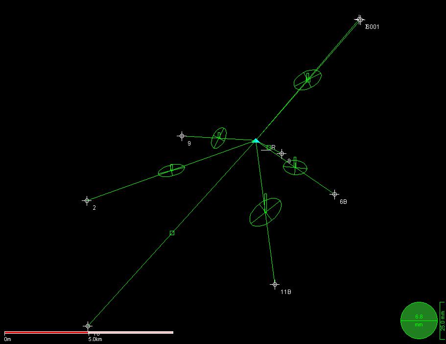
46 46
![Reference point position (base point) Nr R (S015) Coordinate position Number Latitude Longitude Ellips. Height [m] R N 5 34'32.81831" E 95 21'19.12290" -32.](/docs-images/72/67259374/images/47-1.jpg "907 Lat/long Ellipsoid wgs84 Number X[m] Y[m] Orthom. Height [m] R 760928.035 616832.351 2.713 UTM zone 46 North Ellipsoid wgs84 Description located on the parking lot of Banda Aceh BPN offices.")
47 Reference point position (base point) Nr R (S015) Coordinate position Number Latitude Longitude Ellips. Height [m] R N 5 34' " E 95 21' " Lat/long Ellipsoid wgs84 Number X[m] Y[m] Orthom. Height [m] R UTM zone 46 North Ellipsoid wgs84 Description located on the parking lot of Banda Aceh BPN offices. Blue concrete block with precise coordinate position embedded in the block. Part of the geodetic network (re-measured after tsunami. Image 47
![S01.001 Coordinate position Number Latitude Longitude Ellips. Height [m] S001 N 5 38'23.94333" E 95 24'41.20607" -26.981 Lat/long Ellipsoid wgs84 Number X[m] Y[m] Orthom. Height [m] S001 767121.](/docs-images/72/67259374/images/48-0.jpg "096 623960.589 8.289 UTM zone 46 North Ellipsoid wgs84 Description Located around 12 km from BPN offices. Go direction North along the coastline.")
48 S Coordinate position Number Latitude Longitude Ellips. Height [m] S001 N 5 38' " E 95 24' " Lat/long Ellipsoid wgs84 Number X[m] Y[m] Orthom. Height [m] S UTM zone 46 North Ellipsoid wgs84 Description Located around 12 km from BPN offices. Go direction North along the coastline. The point S001 is part of the geodetic network and is embedded in a concrete block painted blue. The point is in the perimeter of a school. Images 48
![Nr 7 Coordinate position Number Latitude Longitude Ellips. Height [m] 7 N 5 38'24.61972" E 95 24'38.68773" -29.607 Lat/long Ellipsoid wgs84 Number X[m] Y[m] Orthom. Height [m] 7 767043.475 623981.](/docs-images/72/67259374/images/49-0.jpg "056 5.668 UTM zone 46 North Ellipsoid wgs84 Description This point is a concrete plate inside the perimeter of a private property.")
49 Nr 7 Coordinate position Number Latitude Longitude Ellips. Height [m] 7 N 5 38' " E 95 24' " Lat/long Ellipsoid wgs84 Number X[m] Y[m] Orthom. Height [m] UTM zone 46 North Ellipsoid wgs84 Description This point is a concrete plate inside the perimeter of a private property. This concrete plate is visible on the VHR satellite imagery (post and Pre). Middle of the plate to be taken as point to measure. It is opposite the entrance of the school where point S001 is located. Images 49
![Nr 8 Coordinate position Number Latitude Longitude Ellips. Height [m] 8 N 5 34'06.](/docs-images/72/67259374/images/50-0.jpg "51355\" E 95 22'08.81356\" -31.464 Lat/long Ellipsoid wgs84 Number X[m] Y[m] Orthom.")
![Height [m] 8 762461.272 616030.095 4.](/docs-images/72/67259374/images/50-1.jpg "035 UTM zone 46 North Ellipsoid wgs84 Description Located inside the perimeter of the")
50 Nr 8 Coordinate position Number Latitude Longitude Ellips. Height [m] 8 N 5 34' " E 95 22' " Lat/long Ellipsoid wgs84 Number X[m] Y[m] Orthom. Height [m] UTM zone 46 North Ellipsoid wgs84 Description Located inside the perimeter of the university campus. The point-location is the corner of a fence. Images 50
![Nr 6B Coordinate position Number Latitude Longitude Ellips. Height [m] 6B N 5 32'47.49184" E 95 23'49.85103" -30.327 Lat/long Ellipsoid wgs84 Number X[m] Y[m] Orthom.](/docs-images/72/67259374/images/51-1.jpg "Height [m] 6B 765582.175 613614.143 4.938 UTM zone 46 North Ellipsoid wgs84 Description The point taken as a GCP is the crossing between 2 raised rice field perimeters.")
51 Nr 6B Coordinate position Number Latitude Longitude Ellips. Height [m] 6B N 5 32' " E 95 23' " Lat/long Ellipsoid wgs84 Number X[m] Y[m] Orthom. Height [m] 6B UTM zone 46 North Ellipsoid wgs84 Description The point taken as a GCP is the crossing between 2 raised rice field perimeters. Images 51
![nr 11B Coordinate position Number Latitude Longitude Ellips. Height [m] 11B N 5 29'54.](/docs-images/72/67259374/images/52-0.jpg "93048\" E 95 21'55.10943\" -27.795 Lat/long Ellipsoid wgs84 Number X[m] Y[m] Orthom.")
![Height [m] 11B 762070.107 608296.87 7.](/docs-images/72/67259374/images/52-1.jpg "731 UTM zone 46 North Ellipsoid wgs84 Description The point taken as a GCP is the")
52 nr 11B Coordinate position Number Latitude Longitude Ellips. Height [m] 11B N 5 29' " E 95 21' " Lat/long Ellipsoid wgs84 Number X[m] Y[m] Orthom. Height [m] 11B UTM zone 46 North Ellipsoid wgs84 Description The point taken as a GCP is the crossing between 2 raised rice field perimeters. Images 52

![175 Lat/long Ellipsoid wgs84 Number X[m] Y[m] Orthom. Height [m] 10 750981.](/docs-images/72/67259374/images/53-1.jpg "212 605833.536 2.")
53 Nr 10 Coordinate position Number Latitude Longitude Ellips. Height [m] 10 N 5 28' " E 95 15' " Lat/long Ellipsoid wgs84 Number X[m] Y[m] Orthom. Height [m] UTM zone 46 North Ellipsoid wgs84 Description Crossing of 2 raised rice field perimeters Images 53
![nr 2 Coordinate position Number Latitude Longitude Ellips. Height [m] 2 N 5 32'38.](/docs-images/72/67259374/images/54-0.jpg "02343\" E 95 15'53.53864\" -33.049 Lat/long Ellipsoid wgs84 Number X[m] Y[m] Orthom.")
![Height [m] 2 750917.088 613265.481 3.](/docs-images/72/67259374/images/54-1.jpg "42 UTM zone 46 North Ellipsoid wgs84 Description Crossing between the edge of the road")
54 nr 2 Coordinate position Number Latitude Longitude Ellips. Height [m] 2 N 5 32' " E 95 15' " Lat/long Ellipsoid wgs84 Number X[m] Y[m] Orthom. Height [m] UTM zone 46 North Ellipsoid wgs84 Description Crossing between the edge of the road and the middle of the river floating under it. Images 54
![nr 9 Coordinate position Number Latitude Longitude Ellips. Height [m] 9 N 5 34'41.81219" E 95 18'56.28323" -33.](/docs-images/72/67259374/images/55-1.jpg "803 Lat/long Ellipsoid wgs84 Number X[m] Y[m] Orthom. Height [m] 9 756528.959 617091.309 2.")
55 nr 9 Coordinate position Number Latitude Longitude Ellips. Height [m] 9 N 5 34' " E 95 18' " Lat/long Ellipsoid wgs84 Number X[m] Y[m] Orthom. Height [m] UTM zone 46 North Ellipsoid wgs84 Description Edge of basin. Images (end document) 55
56 11. Annex 3 Pre and Post tsunami imagery deliverables (on date 2 september 2005) Quickbird images PRE Order ID : Order ID :
57 Order ID : Order ID :
58 Order ID : Order ID :
59 Order ID : Order ID :
60 Order ID :
61 11.2. Quickbird images POST Order ID : Order ID :
62 Order ID : Order ID :
63 Order ID : Order ID :
64 Order ID : Order ID :
65 Order ID : Order ID :
66 Order ID :
67 12. Annex 4: GCP collection Sri Lanka detailed description General information on measured ground control points The coordinates of the GCP s listed above each GCP are in Lat/long wgs84 Ellipsoid and in UTM zone 44 North with wgs84 ellipsoid. 67
![Reference point position (base point) Nr Ref Coordinate position Ellips. Height Number Latitude Longitude [m] ref N 6 07'58.](/docs-images/72/67259374/images/68-0.jpg "59625\" E 81 07'39.98593\" -87.440 Lat/long Ellipsoid wgs84 Orthom. Number X[m] Y[m] Height [m] ref 514137.2 677902.1 9.")

68 Reference point position (base point) Nr Ref Coordinate position Ellips. Height Number Latitude Longitude [m] ref N 6 07' " E 81 07' " Lat/long Ellipsoid wgs84 Orthom. Number X[m] Y[m] Height [m] ref UTM zone 44 North Ellipsoid wgs84 Description used as base-point and which is part of the trigonometric network Sri Lanka. The point is on top of a concrete tower in the backyard of the local land-surveying department in Hambantota. The point itself is imbedded on top of the concrete tower. Image 68
![2 Coordinate position Ellips. Number Latitude Longitude Height [m] 2 N 6 07'12.](/docs-images/72/67259374/images/69-0.jpg "31163\" E 81 04'01.55448\" -94.068 Lat/long Ellipsoid wgs84 Orthom.")
![Number X[m] Y[m] Height [m] 2 507424.1 676479.7 3.](/docs-images/72/67259374/images/69-1.jpg "16 UTM zone 44 North Ellipsoid wgs84 Description Approximately 7 km from the")
69 2 Coordinate position Ellips. Number Latitude Longitude Height [m] 2 N 6 07' " E 81 04' " Lat/long Ellipsoid wgs84 Orthom. Number X[m] Y[m] Height [m] UTM zone 44 North Ellipsoid wgs84 Description Approximately 7 km from the basestation, west direction on the main road. Edge of bridge. Images 69
![2A Coordinate position Ellips. Number Latitude Longitude Height [m] 2A N 6 07'14.](/docs-images/72/67259374/images/70-0.jpg "67724\" E 81 03'56.52463\" -91.002 Lat/long Ellipsoid wgs84 Orthom.")
![Number X[m] Y[m] Height [m] 2A 507269.5 676552.3 6.](/docs-images/72/67259374/images/70-1.jpg "22 UTM zone 44 North Ellipsoid wgs84 Description Inner intersection between 2 roads.")
70 2A Coordinate position Ellips. Number Latitude Longitude Height [m] 2A N 6 07' " E 81 03' " Lat/long Ellipsoid wgs84 Orthom. Number X[m] Y[m] Height [m] 2A UTM zone 44 North Ellipsoid wgs84 Description Inner intersection between 2 roads. Approximately 7 km west of base station. Images 70
![1 Coordinate position Ellips. Number Latitude Longitude Height [m] 1 N 6 09'25.](/docs-images/72/67259374/images/71-0.jpg "78716\" E 81 02'38.83983\" -92.696 Lat/long Ellipsoid wgs84 Orthom.")
![Number X[m] Y[m] Height [m] 1 504881.6 680578 4.](/docs-images/72/67259374/images/71-1.jpg "26 UTM zone 44 North Ellipsoid wgs84 Description Edge of agricultural field.")
71 1 Coordinate position Ellips. Number Latitude Longitude Height [m] 1 N 6 09' " E 81 02' " Lat/long Ellipsoid wgs84 Orthom. Number X[m] Y[m] Height [m] UTM zone 44 North Ellipsoid wgs84 Description Edge of agricultural field. Approximately 9.5 km north-west from base station. Images 71
![3 Coordinate position Ellips. Number Latitude Longitude Height [m] N 6 08'21.](/docs-images/72/67259374/images/72-0.jpg "78588\" E 81 04'26.53353\" -77.249 Lat/long Ellipsoid wgs84 Orthom.")
![Number X[m] Y[m] Height [m] 3 508191.5 678613.1 19.](/docs-images/72/67259374/images/72-1.jpg "86 UTM zone 44 North Ellipsoid wgs84 Description Intersection between 2 roads.")
72 3 Coordinate position Ellips. Number Latitude Longitude Height [m] N 6 08' " E 81 04' " Lat/long Ellipsoid wgs84 Orthom. Number X[m] Y[m] Height [m] UTM zone 44 North Ellipsoid wgs84 Description Intersection between 2 roads. Middle of road at the edge of the other road. Approximately 6 km from basestation. Images 72


73 4 Coordinate position Ellips. Number Latitude Longitude Height [m] 4 N 6 12' " E 81 06' " Lat/long Ellipsoid wgs84 Orthom. Number X[m] Y[m] Height [m] UTM zone 44 North Ellipsoid wgs84 Description Middle of a rock about 9 km north of base-station. Images 73
![5 Coordinate position Ellips. Number Latitude Longitude Height [m] 5A 522542.](/docs-images/72/67259374/images/74-0.jpg "64 691867.14 44.70 Lat/long Ellipsoid wgs84 Orthom.")
![Number X[m] Y[m] Height [m] 5A N 6 15'33.30019" E 81 12'13.64899" -51.](/docs-images/72/67259374/images/74-1.jpg "941 UTM zone 44 North Ellipsoid wgs84 Description Inner intersection 2 roads.")
74 5 Coordinate position Ellips. Number Latitude Longitude Height [m] 5A Lat/long Ellipsoid wgs84 Orthom. Number X[m] Y[m] Height [m] 5A N 6 15' " E 81 12' " UTM zone 44 North Ellipsoid wgs84 Description Inner intersection 2 roads. Approx 16.3 km from base-station. Images 74
![6 Coordinate position Ellips. Number Latitude Longitude Height [m] 6 N 6 12'36.](/docs-images/72/67259374/images/75-0.jpg "34411\" E 81 12'18.10106\" -89.887 Lat/long Ellipsoid wgs84 Orthom.")
![Number X[m] Y[m] Height [m] 6 522681.55 686433.47 7.](/docs-images/72/67259374/images/75-1.jpg "03 UTM zone 44 North Ellipsoid wgs84 Description Crossing of bridge.")
75 6 Coordinate position Ellips. Number Latitude Longitude Height [m] 6 N 6 12' " E 81 12' " Lat/long Ellipsoid wgs84 Orthom. Number X[m] Y[m] Height [m] UTM zone 44 North Ellipsoid wgs84 Description Crossing of bridge. At approximately 12 km from base station Images 75
![7 Coordinate position Ellips. Number Latitude Longitude Height [m] 7 679956.](/docs-images/72/67259374/images/76-0.jpg "050 516323.030-95.458 Lat/long Ellipsoid wgs84 Orthom.")
![Number X[m] Y[m] Height [m] 7 516323.03 679956.05 1.](/docs-images/72/67259374/images/76-1.jpg "70 UTM zone 44 North Ellipsoid wgs84 Description Intersection at dickes of")
76 7 Coordinate position Ellips. Number Latitude Longitude Height [m] Lat/long Ellipsoid wgs84 Orthom. Number X[m] Y[m] Height [m] UTM zone 44 North Ellipsoid wgs84 Description Intersection at dickes of salt ponds.3.1 km from base-station. Images 76

![224 Lat/long Ellipsoid wgs84 Orthom. Number X[m] Y[m] Height [m] 8B 533256.](/docs-images/72/67259374/images/77-1.jpg "42 694339.91 14.")
77 8B Coordinate position Ellips. Number Latitude Longitude Height [m] 8B N 6 16' " E 81 18' " Lat/long Ellipsoid wgs84 Orthom. Number X[m] Y[m] Height [m] 8B UTM zone 44 North Ellipsoid wgs84 Description Intersection between road and ditch. 25 km from basestation. Images 77
![9 Coordinate position Ellips. Number Latitude Longitude Height [m] 9 N 6 12'44.](/docs-images/72/67259374/images/78-0.jpg "75676\" E 81 18'07.16274\" -92.467 Lat/long Ellipsoid wgs84 Orthom.")
![Number X[m] Y[m] Height [m] 9 533408.01 686696.93 4.](/docs-images/72/67259374/images/78-1.jpg "63 UTM zone 44 North Ellipsoid wgs84 Description Intersection road/ditch.")
78 9 Coordinate position Ellips. Number Latitude Longitude Height [m] 9 N 6 12' " E 81 18' " Lat/long Ellipsoid wgs84 Orthom. Number X[m] Y[m] Height [m] UTM zone 44 North Ellipsoid wgs84 Description Intersection road/ditch. Approx km from basestation Images 78

![147 Lat/long Ellipsoid wgs84 Orthom. Number X[m] Y[m] Height [m] 10 542831.](/docs-images/72/67259374/images/79-1.jpg "58 691627.52 2.")
79 10 Coordinate position Ellips. Number Latitude Longitude Height [m] 10 N 6 15' " E 81 23' " Lat/long Ellipsoid wgs84 Orthom. Number X[m] Y[m] Height [m] UTM zone 44 North Ellipsoid wgs84 Description Corner of salt-lake. Approx 31 km from reference station Images 79


![Number X[m] Y[m] Height [m] 11 542541.56 694962.34 8.](/docs-images/72/67259374/images/80-2.jpg "89 UTM zone 44 North Ellipsoid wgs84 Description")
80 11 Coordinate position Ellips. Number Latitude Longitude Height [m] 11 N 6 17' " E 81 23' " Lat/long Ellipsoid wgs84 Orthom. Number X[m] Y[m] Height [m] UTM zone 44 North Ellipsoid wgs84 Description Intersection brigde/river. Approx. 32 km from reference. Images 80
Planet Labs Inc 2017 Page 2
 SKYSAT IMAGERY PRODUCT SPECIFICATION: ORTHO SCENE LAST UPDATED JUNE 2017 SALES@PLANET.COM PLANET.COM Disclaimer This document is designed as a general guideline for customers interested in acquiring Planet
RapidEye Initial findings of Geometric Image Quality Analysis. Joanna Krystyna Nowak Da Costa
 RapidEye Initial findings of Geometric Image Quality Analysis Joanna Krystyna Nowak Da Costa EUR 24129 EN - 2009 The mission of the JRC-IPSC is to provide research results and to support EU policy-makers
News on Image Acquisition for the CwRS Campaign new sensors and changes
 Control Methods Workshop: 6-8 / 4 / 2009 [CwRS KO Meeting Campaign 2009] 1 News on Image Acquisition for the CwRS Campaign 2009 - new sensors and changes Pär Johan Åstrand, Joanna Nowak, Maria Erlandsson
Image Fusion. Pan Sharpening. Pan Sharpening. Pan Sharpening: ENVI. Multi-spectral and PAN. Magsud Mehdiyev Geoinfomatics Center, AIT
 1 Image Fusion Sensor Merging Magsud Mehdiyev Geoinfomatics Center, AIT Image Fusion is a combination of two or more different images to form a new image by using certain algorithms. ( Pohl et al 1998)
Geometric Quality Testing of the WorldView-2 Image Data Acquired over the JRC Maussane Test Site using ERDAS LPS, PCI Geomatics and
 Geometric Quality Testing of the WorldView-2 Image Data Acquired over the JRC Maussane Test Site using ERDAS LPS, PCI Geomatics and Keystone digital photogrammetry software packages Inital Findings Joanna
Geomatica OrthoEngine Orthorectifying SPOT6 data
 Geomatica OrthoEngine Orthorectifying SPOT6 data On September 9, 2012, SPOT 6 was launched adding to the constellation of Earthimaging satellites designed to provide 1.5m high-resolution data. The architecture
News on Image Acquisition for Campaign 2008
 Ispra, 3-4/04/2008 CwRS KO meeting 1 News on Image Acquisition for Campaign 2008 Pär Johan Åstrand, Maria Erlandsson, annian Zhu CID Action Ispra, 3-4/04/2008 CwRS KO meeting 2 Outline of presentation
LPIS Orthoimagery An assessment of the Bing imagery for LPIS purpose
 LPIS Orthoimagery An assessment of the Bing imagery for LPIS purpose Slavko Lemajić Wim Devos, Pavel Milenov GeoCAP Action - MARS Unit - JRC Ispra Tallinn, 24 th November 2011 Outline JRC`s Ortho specifications
Baldwin and Mobile Counties, AL Orthoimagery Project Report. Submitted: March 23, 2016
 2015 Orthoimagery Project Report Submitted: Prepared by: Quantum Spatial, Inc 523 Wellington Way, Suite 375 Lexington, KY 40503 859-277-8700 Page i of iii Contents Project Report 1. Summary / Scope...
[GEOMETRIC CORRECTION, ORTHORECTIFICATION AND MOSAICKING]
![[GEOMETRIC CORRECTION, ORTHORECTIFICATION AND MOSAICKING]](/thumbs/78/78211997.jpg "[GEOMETRIC CORRECTION, ORTHORECTIFICATION AND MOSAICKING]") 2013 Ogis-geoInfo Inc. IBEABUCHI NKEMAKOLAM.J [GEOMETRIC CORRECTION, ORTHORECTIFICATION AND MOSAICKING] [Type the abstract of the document here. The abstract is typically a short summary of the contents
2013 Ogis-geoInfo Inc. IBEABUCHI NKEMAKOLAM.J [GEOMETRIC CORRECTION, ORTHORECTIFICATION AND MOSAICKING] [Type the abstract of the document here. The abstract is typically a short summary of the contents
Abstract Quickbird Vs Aerial photos in identifying man-made objects
 Abstract Quickbird Vs Aerial s in identifying man-made objects Abdullah Mah abdullah.mah@aramco.com Remote Sensing Group, emap Division Integrated Solutions Services Department (ISSD) Saudi Aramco, Dhahran
Remote sensing image correction
 Remote sensing image correction Introductory readings remote sensing http://www.microimages.com/documentation/tutorials/introrse.pdf 1 Preprocessing Digital Image Processing of satellite images can be
Orthorectified imagery is widely
 Geometric Quality Assessment of Or By Simon Kay, Peter Spruyt, Abstract Two QuickBird images delivered in basic and standard processed formats and an IKOOS Geo-processed image, covering an area of 108km
TEMPORAL ANALYSIS OF MULTI EPOCH LANDSAT GEOCOVER IMAGES IN ZONGULDAK TESTFIELD
 TEMPORAL ANALYSIS OF MULTI EPOCH LANDSAT GEOCOVER IMAGES IN ZONGULDAK TESTFIELD Şahin, H. a*, Oruç, M. a, Büyüksalih, G. a a Zonguldak Karaelmas University, Zonguldak, Turkey - (sahin@karaelmas.edu.tr,
ENVI Tutorial: Orthorectifying Aerial Photographs
 ENVI Tutorial: Orthorectifying Aerial Photographs Table of Contents OVERVIEW OF THIS TUTORIAL...2 ORTHORECTIFYING AERIAL PHOTOGRAPHS IN ENVI...2 Building the interior orientation...3 Building the exterior
REGISTRATION OF OPTICAL AND SAR SATELLITE IMAGES BASED ON GEOMETRIC FEATURE TEMPLATES
 REGISTRATION OF OPTICAL AND SAR SATELLITE IMAGES BASED ON GEOMETRIC FEATURE TEMPLATES N. Merkle, R. Müller, P. Reinartz German Aerospace Center (DLR), Remote Sensing Technology Institute, Oberpfaffenhofen,
CanImage. (Landsat 7 Orthoimages at the 1: Scale) Standards and Specifications Edition 1.0
 Standards and Specifications Edition 1.0") CanImage (Landsat 7 Orthoimages at the 1:50 000 Scale) Standards and Specifications Edition 1.0 Centre for Topographic Information Customer Support Group 2144 King Street West, Suite 010 Sherbrooke, QC
CanImage (Landsat 7 Orthoimages at the 1:50 000 Scale) Standards and Specifications Edition 1.0 Centre for Topographic Information Customer Support Group 2144 King Street West, Suite 010 Sherbrooke, QC
Automatic geo-registration of satellite imagery
 Fjärranalysdagarna 10-11 mars 2009 Automatic geo-registration of satellite imagery Torbjörn Westin Lars-Åke Edgardh Ian Spence Spacemetric AB www.spacemetric.com Keystone Image Server Keystone is an automatic
PLANET IMAGERY PRODUCT SPECIFICATIONS PLANET.COM
 PLANET IMAGERY PRODUCT SPECIFICATIONS SUPPORT@PLANET.COM PLANET.COM LAST UPDATED JANUARY 2018 TABLE OF CONTENTS LIST OF FIGURES 3 LIST OF TABLES 4 GLOSSARY 5 1. OVERVIEW OF DOCUMENT 7 1.1 Company Overview
Topographic mapping from space K. Jacobsen*, G. Büyüksalih**
 Topographic mapping from space K. Jacobsen*, G. Büyüksalih** * Institute of Photogrammetry and Geoinformation, Leibniz University Hannover ** BIMTAS, Altunizade-Istanbul, Turkey KEYWORDS: WorldView-1,
Geomatica OrthoEngine v10.2 Tutorial Orthorectifying ALOS PRISM Data Rigorous and RPC Modeling
 Geomatica OrthoEngine v10.2 Tutorial Orthorectifying ALOS PRISM Data Rigorous and RPC Modeling ALOS stands for Advanced Land Observing Satellite and was developed by the Japan Aerospace Exploration Agency
INTEGRATED DEM AND PAN-SHARPENED SPOT-4 IMAGE IN URBAN STUDIES
 INTEGRATED DEM AND PAN-SHARPENED SPOT-4 IMAGE IN URBAN STUDIES G. Doxani, A. Stamou Dept. Cadastre, Photogrammetry and Cartography, Aristotle University of Thessaloniki, GREECE gdoxani@hotmail.com, katerinoudi@hotmail.com
EVALUATION OF PLEIADES-1A TRIPLET ON TRENTO TESTFIELD
 EVALUATION OF PLEIADES-1A TRIPLET ON TRENTO TESTFIELD D. Poli a, F. Remondino b, E. Angiuli c, G. Agugiaro b a Terra Messflug GmbH, Austria b 3D Optical Metrology Unit, Fondazione Bruno Kessler, Trento,
What makes the positioning infrastructure work. Simon Kwok Chairman, Land Surveying Division Hong Kong Institute of Surveyors
 What makes the positioning infrastructure work The experience of the Hong Kong Satellite Positioning Reference Station Network Simon Kwok Chairman, Land Surveying Division Hong Kong Institute of Surveyors
GROUND CONTROL SURVEY REPORT
 GROUND CONTROL SURVEY REPORT Services provided by: 3001, INC. a Northrop Grumman company 10300 Eaton Place Suite 340 Fairfax, VA 22030 Ground Control Survey in Support of Topographic LIDAR, RGB Imagery
Landsat 8. Snabba leveranser av bilder till användarna. Lars-Åke Edgardh. tisdag 9 april 13
 Landsat 8 Snabba leveranser av bilder till användarna Lars-Åke Edgardh Keystone A single system for: Many sensors Many types of clients Hides the complexity of sensors. Specialised on: Services High volume
New sensors benchmark report on KOMPSAT-3A
 New sensors benchmark report on KOMPSAT-3A Geometric benchmarking over Maussane test site for CAP purposes Blanka Vajsova Agnieszka Walczynska Samuel Bärisch Pär Johan Åstrand Melanie Rankl 2018 EUR 29331
PLANET IMAGERY PRODUCT SPECIFICATION: PLANETSCOPE & RAPIDEYE
 PLANET IMAGERY PRODUCT SPECIFICATION: PLANETSCOPE & RAPIDEYE LAST UPDATED OCTOBER 2016 SALES@PLANET.COM PLANET.COM Table of Contents LIST OF FIGURES 3 LIST OF TABLES 3 GLOSSARY 5 1. OVERVIEW OF DOCUMENT
SPOT 5 / HRS: a key source for navigation database
 SPOT 5 / HRS: a key source for navigation database CONTENT DEM and satellites SPOT 5 and HRS : the May 3 rd 2002 revolution Reference3D : a tool for navigation and simulation Marc BERNARD Page 1 Report
GEOMETRIC RECTIFICATION OF EUROPEAN HISTORICAL ARCHIVES OF LANDSAT 1-3 MSS IMAGERY
 GEOMETRIC RECTIFICATION OF EUROPEAN HISTORICAL ARCHIVES OF LANDSAT -3 MSS IMAGERY Torbjörn Westin Satellus AB P.O.Box 427, SE-74 Solna, Sweden tw@ssc.se KEYWORDS: Landsat, MSS, rectification, orbital model
TechTime New Mapping Tools for Transportation Engineering
 GeoEye-1 Stereo Satellite Imagery Presented by Karl Kliparchuk, M.Sc., GISP kkliparchuk@mcelhanney.com 604-683-8521 All satellite imagery are copyright GeoEye Corp GeoEye-1 About GeoEye Corp Headquarters:
Orthoimagery Standards. Chatham County, Georgia. Jason Lee and Noel Perkins
 1 Orthoimagery Standards Chatham County, Georgia Jason Lee and Noel Perkins 2 Table of Contents Introduction... 1 Objective... 1.1 Data Description... 2 Spatial and Temporal Environments... 3 Spatial Extent
INFORMATION CONTENT ANALYSIS FROM VERY HIGH RESOLUTION OPTICAL SPACE IMAGERY FOR UPDATING SPATIAL DATABASE
 INFORMATION CONTENT ANALYSIS FROM VERY HIGH RESOLUTION OPTICAL SPACE IMAGERY FOR UPDATING SPATIAL DATABASE M. Alkan a, * a Department of Geomatics, Faculty of Civil Engineering, Yıldız Technical University,
VHR Image Specifications for the CwRS Programme Campaign 2008
 VHR Image Specifications for the CwRS Programme Campaign 2008 Pär-Johan Åstrand, Maria Erlandsson EUR 23404 EN - 2008 The Institute for the Protection and Security of the Citizen provides research-based,
NUCLEAR WASTE RELATED SATELLITE MAPPING IN NORTHWEST RUSSIA
 NUCLEAR WASTE RELATED SATELLITE MAPPING IN NORTHWEST RUSSIA O. B.Dick a, *, O. Reistad b, S. Hustveit b, G. Grepstad c, Frits Steenhuisen d a Geomatics section - IMT, Norwegian University of Life Sciences,
Progress Towards the Seamless Combination of Bathymetric and Topographic Data in New Zealand
 Progress Towards the Seamless Combination of Bathymetric and Topographic Data in New Zealand Matt Amos Senior Technical Advisor National Geodetic Office Introduction Datasets usually defined in terms of
The Most Suitable Sizes Of Ground Control Points (Gcps) For World View2
 For World View2") The Most Suitable Sizes Of Ground Control Points (Gcps) For World View2 Dr. O. Mutluoglu Dr.M. Yakar Dr. H.M. Yilmaz 1 INTRODUCTION High resolution satellite images, (less than 1 m. Resolution) are used
The Most Suitable Sizes Of Ground Control Points (Gcps) For World View2 Dr. O. Mutluoglu Dr.M. Yakar Dr. H.M. Yilmaz 1 INTRODUCTION High resolution satellite images, (less than 1 m. Resolution) are used
Geomatica OrthoEngine v10.2 Tutorial DEM Extraction of GeoEye-1 Data
 Geomatica OrthoEngine v10.2 Tutorial DEM Extraction of GeoEye-1 Data GeoEye 1, launched on September 06, 2008 is the highest resolution commercial earth imaging satellite available till date. GeoEye-1
Image Acquisition Campaign 2008
 Madrid, 12-14 November, 2007 Geomatics in Support of the CAP 1 Image Acquisition Campaign 2008 Pär Johan Åstrand, Maria Erlandsson Mihaela Fotin, Cherith Aspinall JRC, CID JRC, CID Madrid, 12-14 November,
New sensors benchmark report on Sentinel-2B
 New sensors benchmark report on Sentinel-2B Geometric benchmarking test for CAP purposes Blanka Vajsova Pär Johan Åstrand 2017 EUR 28760 EN This publication is a Technical report by the Joint Research
CALIBRATION OF OPTICAL SATELLITE SENSORS
 CALIBRATION OF OPTICAL SATELLITE SENSORS KARSTEN JACOBSEN University of Hannover Institute of Photogrammetry and Geoinformation Nienburger Str. 1, D-30167 Hannover, Germany jacobsen@ipi.uni-hannover.de
DEM GENERATION WITH WORLDVIEW-2 IMAGES
 DEM GENERATION WITH WORLDVIEW-2 IMAGES G. Büyüksalih a, I. Baz a, M. Alkan b, K. Jacobsen c a BIMTAS, Istanbul, Turkey - (gbuyuksalih, ibaz-imp)@yahoo.com b Zonguldak Karaelmas University, Zonguldak, Turkey
Pléiades. Access to data. Charlotte Gabriel-Robez. January Pléiades product manager
 Pléiades Access to data Charlotte Gabriel-Robez Pléiades product manager January 2012 A variety of users 2008: Delegation of Public Service Granted by CNES to Spot Image Astrium Services (ex. Spot Image)
The Airphoto Ortho Suite is an add-on to Geomatica. It requires Geomatica Core or Geomatica Prime as a pre-requisite.
 Airphoto Ortho Suite The Airphoto Ortho Suite includes rigorous models used to correct the geometry of analogue and digital/video cameras and to produce orthorectified air photos. These models compensate
Satellite Imagery Characteristics, Uses and Delivery to GIS Systems. Wayne Middleton April 2014
 Satellite Imagery Characteristics, Uses and Delivery to GIS Systems Wayne Middleton April 2014 About Geoimage Founded in Brisbane 1988 Leading Independent company Specialists in satellite imagery and geospatial
FieldGenius Technical Notes GPS Terminology
 FieldGenius Technical Notes GPS Terminology Almanac A set of Keplerian orbital parameters which allow the satellite positions to be predicted into the future. Ambiguity An integer value of the number of
Satellite Ortho Suite
 Technical Specifications Satellite Ortho Suite The Satellite Ortho Suite includes rigorous and rational function models developed to compensate for distortions and produce orthorectified satellite images
SAR Othorectification and Mosaicking
 White Paper SAR Othorectification and Mosaicking John Wessels: Senior Scientist PCI Geomatics SAR Othorectification and Mosaicking This study describes the high-speed orthorectification and mosaicking
Summary of the VHR image acquisition Campaign 2014 and new sensors for 2015
 Summary of the VHR image acquisition Campaign 2014 and new sensors for 2015 Michaela Neumann, George Ellis, Samuel Bärisch, Blanka Vajsova 19 November 2014, Dresden 20th MARS Conference Presentation Outline
Accuracy Evaluation Internet-Based GNSS for Kinematic Surveying the Case Study in Thailand
 Accuracy Evaluation Internet-Based GNSS for Kinematic Surveying the Case Study in Thailand Kritsada Anantakarn 1 1 Faculty of Engineering and Architectural : Uthenthawai campus. Rajamongala University
E m e r g e n c y M a n a g e m e n t S e r v i c e. C o p e r n i c u s A e r i a l c o m p o n e n t s t a t u s s t u d y
 E m e r g e n c y M a n a g e m e n t S e r v i c e C o p e r n i c u s A e r i a l c o m p o n e n t s t a t u s s t u d y Peter Spruyt European Commission Joint Research Centre EMS Mapping User Workshop
Geomatica OrthoEngine V10.3 Tutorial. Orthorectifying AVNIR-2 Data Rigorous and RPC Modeling
 Geomatica OrthoEngine V10.3 Tutorial Orthorectifying AVNIR-2 Data Rigorous and RPC Modeling AVNIR-2 stands for Advanced Visible and Near Infrared Radiometer Type 2. It is a successor of AVNIR-1 and is
The Radar Ortho Suite is an add-on to Geomatica. It requires Geomatica Core or Geomatica Prime as a pre-requisite.
 Technical Specifications Radar Ortho Suite The Radar Ortho Suite includes rigorous and rational function models developed to compensate for distortions and produce orthorectified radar images. Distortions
Flood modelling and management. Glasgow University. 8 September Paul Shaw - GeoVision
 Flood modelling and management Glasgow University 8 September 2004 Paul Shaw - GeoVision How important are heights in flood modelling? Comparison of data collection technologies GPS - Global Positioning
Introduction to WG5 on CwRS imagery use and alternatives and QE5 on claimed rate inside the RP Peter Viskum Jørgensen, FERV and Birger Faurholt
 Introduction to WG5 on CwRS imagery use and alternatives and QE5 on claimed rate inside the RP Peter Viskum Jørgensen, FERV and Birger Faurholt Pedersen, University of Aarhus, DK CwRS Imagery use and alternatives
Contributions of the Remote Sensing by Earth Observation Satellites on Engineering Geology
 10th Asian Regional Conference of IAEG (2015) Contributions of the Remote Sensing by Earth Observation Satellites on Engineering Geology Takeo TADONO (1), Hiroto NAGAI (1), Atsuko NONOMURA (2) and Ryoichi
Section 2 Image quality, radiometric analysis, preprocessing
 Section 2 Image quality, radiometric analysis, preprocessing Emmanuel Baltsavias Radiometric Quality (refers mostly to Ikonos) Preprocessing by Space Imaging (similar by other firms too): Modulation Transfer
VHR Image Specifications for the CwRS Programme Campaign Pär Johan Åstrand Maria Erlandsson
 VHR Image Specifications for the CwRS Programme Campaign 2009 Pär Johan Åstrand Maria Erlandsson EUR 23404 EN/2-2009 The mission of the JRC-IPSC is to provide research results and to support EU policy-makers
Windstorm Simulation & Modeling Project
 Windstorm Simulation & Modeling Project Manatee County Digital Elevation Models Preliminary Report Prepared for: The Manatee County Public Safety Department 1112 Manatee Avenue West, Suite 525 Bradenton,
ASTER GDEM Version 2 Validation Report
 ASTER GDEM Version 2 Validation Report Japan s Validation Report August 12th, 2011 Tetsushi Tachikawa (ERSDAC) Manabu Kaku (Mitsubishi Material Techno Corp.) Akira Iwasaki (University of Tokyo) ---------------------------------------------------------------------------------------
EnsoMOSAIC Aerial mapping tools
 EnsoMOSAIC Aerial mapping tools Jakarta and Kuala Lumpur, 2013 Contents MosaicMill MM Application examples Software introduction System introduction Rikola HS sensor UAV platform examples SW Syst HS UAV
COMPARISON OF INFORMATION CONTENTS OF HIGH RESOLUTION SPACE IMAGES
 COMPARISON OF INFORMATION CONTENTS OF HIGH RESOLUTION SPACE IMAGES H. Topan*, G. Büyüksalih*, K. Jacobsen ** * Karaelmas University Zonguldak, Turkey ** University of Hannover, Germany htopan@karaelmas.edu.tr,
Guidelines for Laying Targets for Ground Control Points
 Guidelines for Laying Targets for Ground Control Points Overview of target requirements: Three to four unambiguous ground survey targets, recognizable in the satellite photo, are requested. The survey
Tutorial 10 Information extraction from high resolution optical satellite sensors
 Tutorial 10 Information extraction from high resolution optical satellite sensors Karsten Jacobsen 1, Emmanuel Baltsavias 2, David Holland 3 1 University of, Nienburger Strasse 1, D-30167, Germany, jacobsen@ipi.uni-hannover.de
Potential of ASTER and LANDSAT Images for Mapping Features in Western Desert
 522 Potential of ASTER and LANDSAT Images for Mapping Features in Western Desert Mahmoud El Nokrashy Osman Ali, Ibrahim Fathy Mohamed Shaker, Nasr Mohammady Saba Abstract: In Egypt, most of the topographic
NR402 GIS Applications in Natural Resources
 NR402 GIS Applications in Natural Resources Lesson 5 GPS/GIS integration Global Positioning System (GPS)..a global navigation system that everyone can use What is GPS? How does it work? How accurate is
Aerial photography: Principles. Frame capture sensors: Analog film and digital cameras
 Aerial photography: Principles Frame capture sensors: Analog film and digital cameras Overview Introduction Frame vs scanning sensors Cameras (film and digital) Photogrammetry Orthophotos Air photos are
ANALYSIS OF SRTM HEIGHT MODELS
 ANALYSIS OF SRTM HEIGHT MODELS Sefercik, U. *, Jacobsen, K.** * Karaelmas University, Zonguldak, Turkey, ugsefercik@hotmail.com **Institute of Photogrammetry and GeoInformation, University of Hannover,
Technical Evaluation of Khartoum State Mapping Project
 Technical Evaluation of Khartoum State Mapping Project Nagi Zomrawi 1 and Mohammed Fator 2 1 School of Surveying Engineering, Collage of Engineering, Sudan University of Science and Technology, Khartoum,
HIGH RESOLUTION COLOR IMAGERY FOR ORTHOMAPS AND REMOTE SENSING. Author: Peter Fricker Director Product Management Image Sensors
 HIGH RESOLUTION COLOR IMAGERY FOR ORTHOMAPS AND REMOTE SENSING Author: Peter Fricker Director Product Management Image Sensors Co-Author: Tauno Saks Product Manager Airborne Data Acquisition Leica Geosystems
High Mountain Asia 8-meter DEMs Derived from Along-track Optical Imagery. High Mountain Asia 8-meter DEMs Derived from Cross-track Optical Imagery
 This user guide covers the following data sets: High Mountain Asia 8-meter DEMs Derived from Along-track Optical Imagery High Mountain Asia 8-meter DEMs Derived from Cross-track Optical Imagery Table of
IMAGE DATA AND TEST FIELD
 Georeferencing Accuracy of Ge With bias-corrected RPCs and a single GCP, the RMS georeferencing accuracy of GeoEye-1 stereo imagery reaches the unprecedented level of 0.10m (0.2 pixel) in planimetry and
DIFFERENTIAL APPROACH FOR MAP REVISION FROM NEW MULTI-RESOLUTION SATELLITE IMAGERY AND EXISTING TOPOGRAPHIC DATA
 DIFFERENTIAL APPROACH FOR MAP REVISION FROM NEW MULTI-RESOLUTION SATELLITE IMAGERY AND EXISTING TOPOGRAPHIC DATA Costas ARMENAKIS Centre for Topographic Information - Geomatics Canada 615 Booth Str., Ottawa,
Guidelines for Best Practice and Quality Checking of Ortho Imagery
 Guidelines for Best Practice and Quality Checking of Ortho Imagery Issue 3.0 Dimitrios Kapnias, Pavel Milenov and Simon Kay EUR 23638 EN - 2008 The Institute for the Protection and Security of the Citizen
Using High-Res. Orthoimagery for Environmental Change Detection & Analysis in Northern Alaska
 Using High-Res. Orthoimagery for Environmental Change Detection & Analysis in Northern Alaska William F. Manley Leanne R. Lestak INSTAAR, University of Colorado INSTAAR, University of Colorado 1 Talk Outline
ENVI Orthorectification Module
 ENVI Orthorectification Module Orthorectify your imagery quickly and easily. CREASO - your partner for visual information solutions Rigorous Orthorectification. Simple Workflow. Trusted Method. The Need
DEMS BASED ON SPACE IMAGES VERSUS SRTM HEIGHT MODELS. Karsten Jacobsen. University of Hannover, Germany
 DEMS BASED ON SPACE IMAGES VERSUS SRTM HEIGHT MODELS Karsten Jacobsen University of Hannover, Germany jacobsen@ipi.uni-hannover.de Key words: DEM, space images, SRTM InSAR, quality assessment ABSTRACT
SUPPORT OF NETWORK FORMATS BY TRIMBLE GPSNET NETWORK RTK SOLUTION
 SUPPORT OF NETWORK FORMATS BY TRIMBLE GPSNET NETWORK RTK SOLUTION TRIMBLE TERRASAT GMBH, HARINGSTRASSE 19, 85635 HOEHENKIRCHEN, GERMANY STATUS The Trimble GPSNet network RTK solution was first introduced
PLANET IMAGERY PRODUCT SPECIFICATION: PLANETSCOPE & RAPIDEYE
 PLANET IMAGERY PRODUCT SPECIFICATION: PLANETSCOPE & RAPIDEYE LAST UPDATED FEBRUARY 2017 SALES@PLANET.COM PLANET.COM Table of Contents LIST OF FIGURES 3 LIST OF TABLES 3 GLOSSARY 5 1. OVERVIEW OF DOCUMENT
CHARACTERISTICS OF VERY HIGH RESOLUTION OPTICAL SATELLITES FOR TOPOGRAPHIC MAPPING
 CHARACTERISTICS OF VERY HIGH RESOLUTION OPTICAL SATELLITES FOR TOPOGRAPHIC MAPPING K. Jacobsen Leibniz University Hannover, Institute of Photogrammetry and Geoinformation jacobsen@ipi.uni-hannover.de Commission
FEDERAL SPACE AGENCY SOVZOND JSC компания «Совзонд»
 FEDERAL SPACE AGENCY Resurs-DK.satellite SOVZOND JSC SPECIFICATIONS Launch date June 15, 2006 Carrier vehicle Soyuz Orbit Elliptical Altitude 360-604 km Revisit frequency (at nadir) 6 days Inclination
ANNEX IV ERDAS IMAGINE OPERATION MANUAL
 ANNEX IV ERDAS IMAGINE OPERATION MANUAL Table of Contents 1. TOPIC 1 DATA IMPORT...1 1.1. Importing SPOT DATA directly from CDROM... 1 1.2. Importing SPOT (Panchromatic) using GENERIC BINARY... 7 1.3.
School of Rural and Surveying Engineering National Technical University of Athens
 Laboratory of Photogrammetry National Technical University of Athens Combined use of spaceborne optical and SAR data Incompatible data sources or a useful procedure? Charalabos Ioannidis, Dimitra Vassilaki
THREE-DIMENSIONAL MAPPING USING BOTH AIRBORNE AND SPACEBORNE IFSAR TECHNOLOGIES ABSTRACT INTRODUCTION
 THREE-DIMENSIONAL MAPPING USING BOTH AIRBORNE AND SPACEBORNE IFSAR TECHNOLOGIES Trina Kuuskivi Manager of Value Added Products and Services, Intermap Technologies Corp. 2 Gurdwara Rd, Suite 200, Ottawa,
Role, Workflow and Challenges
 1 Workshop on checks and management of agricultural land in IACS The actual use of imagery Image Processing at EFTAS Role, Workflow and Challenges Head of IT, Image Processing Unit CwRS 2 The Role 30 years
Advanced Techniques in Urban Remote Sensing
 Advanced Techniques in Urban Remote Sensing Manfred Ehlers Institute for Geoinformatics and Remote Sensing (IGF) University of Osnabrueck, Germany mehlers@igf.uni-osnabrueck.de Contents Urban Remote Sensing:
ERDAS IMAGINE Suite Comparison
 ERDAS Suite Comparison A brief comparison of Essentials, Advantage and Professional age 1 of 7 Overview This document provides a brief comparison of the main features and capabilities found within the
EXPERIMENTAL TESTS ON FAST AMBIGUITY SOLUTIONS FOR AIRBORNE KINEMATIC GPS POSITIONING
 EXPERIMENTAL TESTS ON FAST AMBIGUITY SOLUTIONS FOR AIRBORNE KINEMATIC GPS POSITIONING Prof. em. Friedrich Ackermann Institute of Photogrammetry University of Stuttgart Keplerstr. 11, 70174 Stuttgart Germany
CALIBRATION OF IMAGING SATELLITE SENSORS
 CALIBRATION OF IMAGING SATELLITE SENSORS Jacobsen, K. Institute of Photogrammetry and GeoInformation, University of Hannover jacobsen@ipi.uni-hannover.de KEY WORDS: imaging satellites, geometry, calibration
INTERNATIONAL JOURNAL OF GEOMATICS AND GEOSCIENCES Volume 2, No 3, 2012
 INTERNATIONAL JOURNAL OF GEOMATICS AND GEOSCIENCES Volume 2, No 3, 2012 Copyright 2010 All rights reserved Integrated Publishing services Research article ISSN 0976 4380 Generation and evaluation of Cartosat
Introduction of CSRSR Image product processing systems in CSRSR Disaster monitoring and data processing
 3 rd Joint Project Team Meeting for Sentinel Asia STEP3 Data Analysis Node Report Li-Yu Chang Associate Research Engineer Center for Space and Remote Sensing Research National Central University, Taiwan
Option 1. Design Options are diverse e.g. new route alignments covering a wide area. Option 2. Design Options are restricted
 MINIMUM STANDARD Z/16 SURVEY SPECIFICATIONS 1. GENERAL This specification sets out the Consultant s requirements for topographical survey (ground and aerial) for the Detailed Business Case (DBC) and Pre-Implementation
Evaluation of DEM, and orthoimage generated from Cartosat-1 with its potential for feature extraction and visualization
 American Journal of Remote Sensing 2013; 1(1) : 1-6 Published online February 20, 2013 (http://www.sciencepublishinggroup.com/j/ajrs) doi: 10.11648/j. ajrs.20130101.11 Evaluation of DEM, and orthoimage
What can we check with VHR Pan and HR multispectral imagery?
 2008 CwRS Campaign Kick-off meeting, Ispra, 03-04 April 2008 1 What can we check with VHR Pan and HR multispectral imagery? Pavel MILENOV GeoCAP, Agriculture Unit, JRC 2008 CwRS Campaign Kick-off meeting,
ENVI Orthorectification Module
 Visual Information Solutions ENVI Orthorectification Module Orthorectify Your Imagery Quickly and Easily. Rigorous Orthorectification. Simple Workflow. Trusted Method. The Need for Orthorectification Satellite
The Reasons to Succeed or to Fail a GNSS Network RTK Project
 The Reasons to Succeed or to Fail a GNSS Network RTK Project Joël van Cranenbroeck, Managing Director CGEOS Creative Geosensing sprl-s, Belgium Andy Yin, International Sales Director ComNav Technology
LONG STRIP MODELLING FOR CARTOSAT-1 WITH MINIMUM CONTROL
 LONG STRIP MODELLING FOR CARTOSAT-1 WITH MINIMUM CONTROL Amit Gupta a, *, Jagjeet Singh Nain a, Sanjay K Singh a, T P Srinivasan a, B Gopala Krishna a, P K Srivastava a a Space Applications Centre, Indian
PRODUCT LEVELS 2 Georectified Products... 3 Orthorectified Products... 4 Stereo Products... 5 Off-the-Shelf Products... 6
 i TABLE OF CONTENTS INTRODUCTION 1 PRODUCT LEVELS 2 Georectified Products... 3 Orthorectified Products... 4 Stereo Products... 5 Off-the-Shelf Products... 6 SPECIFICATIONS 7 Spectral Range... 7 Clouds...
ASTER GDEM Readme File ASTER GDEM Version 1
 I. Introduction ASTER GDEM Readme File ASTER GDEM Version 1 The Advanced Spaceborne Thermal Emission and Reflection Radiometer (ASTER) Global Digital Elevation Model (GDEM) was developed jointly by the
ROLE OF SATELLITE DATA APPLICATION IN CADASTRAL MAP AND DIGITIZATION OF LAND RECORDS DR.T. RAVISANKAR GROUP HEAD (LRUMG) RSAA/NRSC/ISRO /DOS HYDERABAD
 RSAA/NRSC/ISRO /DOS HYDERABAD") ROLE OF SATELLITE DATA APPLICATION IN CADASTRAL MAP AND DIGITIZATION OF LAND RECORDS DR.T. RAVISANKAR GROUP HEAD (LRUMG) RSAA/NRSC/ISRO /DOS HYDERABAD WORKSHOP on Best Practices under National Land Records
ROLE OF SATELLITE DATA APPLICATION IN CADASTRAL MAP AND DIGITIZATION OF LAND RECORDS DR.T. RAVISANKAR GROUP HEAD (LRUMG) RSAA/NRSC/ISRO /DOS HYDERABAD WORKSHOP on Best Practices under National Land Records