(12) United States Patent (10) Patent N0.: US 8,314,999 B1 Tsai (45) Date of Patent: Nov. 20, 2012
|
|
|
- Lenard Wilcox
- 6 years ago
- Views:
Transcription
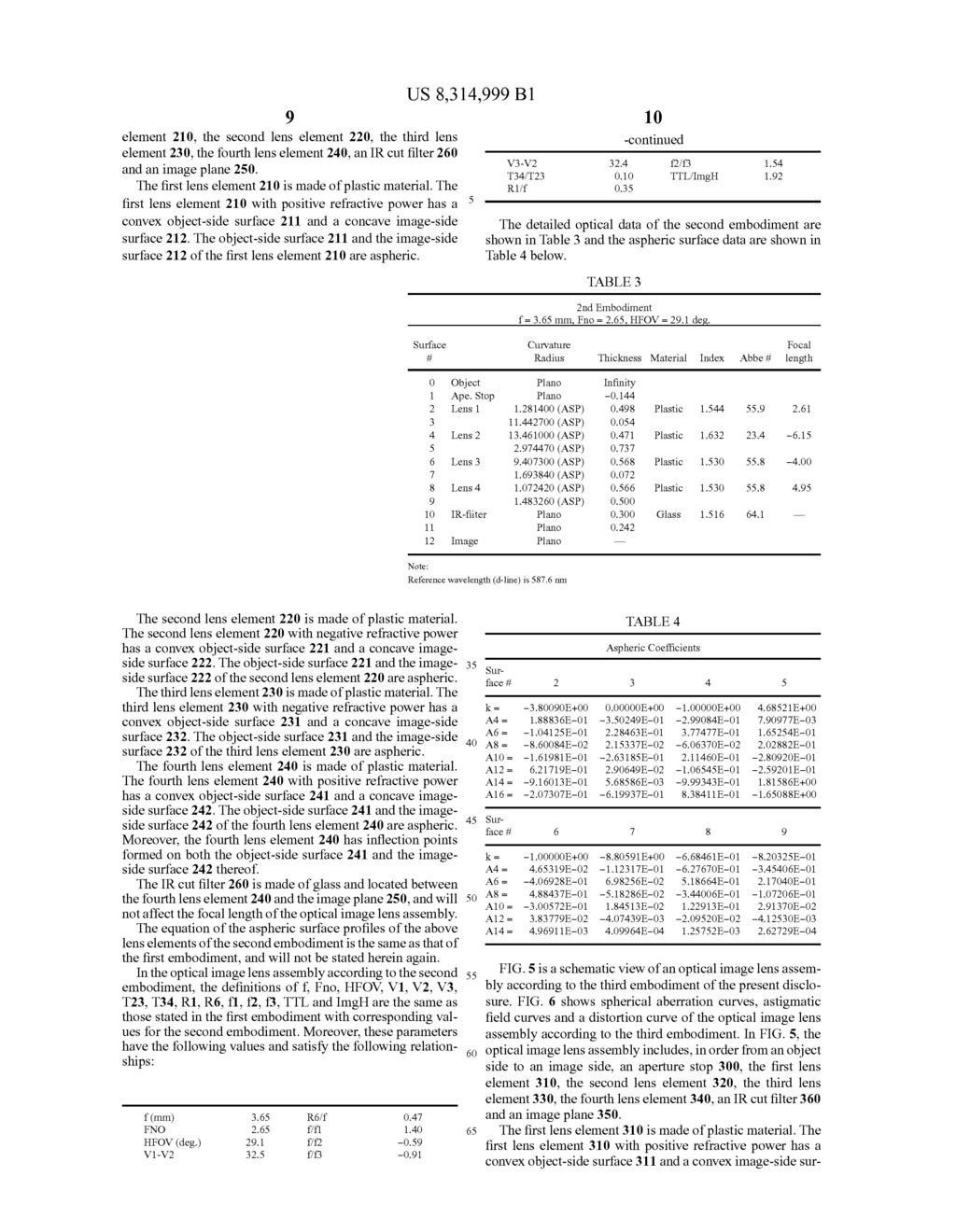
1 US0083 l4999bl (12) United States Patent (10) Patent N0.: US 8,314,999 B1 Tsai (45) Date of Patent: Nov. 20, 2012 (54) OPTICAL IMAGE LENS ASSEMBLY (58) Field Of Classi?cation Search /715, _ 359/771, 772, 775 (75) Inventor: TSllng-Hall TSai, Talchllng (TW) See application?le for complete search history. (73) Assignee: Largan Precision Co., Ltd., Taichung (56) References Cited (TW) U.S. PATENT DOCUMENTS ( ) Notice. Subject to any disclaimer, the term ofth1s 7,145,736 B2 12/2006 Noda patent is extended or adjusted under 35 7,365,920 B2 4/2008 Noda U.S.C. 154(b) by 0 days. _ Primary Examiner * Jack Dinh (21) App1_ NO; 13/226,505 (74) Attorney, Agent, or Firm * CKC & Partners Co., Ltd. (22) Filed: Sep. 7, 2011 (57) ABSTRACT (30) Foreign Application Priority Data An optical image lens assembly includes, in order from an object side to an image side, a?rst lens element With positive refractive power and having a convex object-side surface, a May 16, 2011 (TW) ~~~~~~~~~~~~~~~~~~~~~~~~~~~ A second lens element With negative refractive power, a third lens element With negative refractive power and having a (51) Int- Cl- convex object-side surface and a concave image-side surface, G02B 3/02 ( ) and a fourth lens element With refractive power and having a G02B 9/34 ( ) concave image-side surface. G02B 9/36 ( ) (52) US. Cl /715; 359/772; 359/ Claims, 16 Drawing Sheets 11}
2 US. Patent Nov. 20, 2012 Sheet 1 0f 16 US 8,314,999 B1
3
4 US. Patent Nov. 20, 2012 Sheet 3 0f 16 US 8,314,999 B1 2mm V emrm Ll
5 US. Patent Nov. 20, 2012 Sheet 4 0f 16 US 8,314,999 B1 95m.mmw 1111 i
6 US. Patent Nov. 20, 2012 Sheet 5 0f 16 US 8,314,999 B1
7 US. Patent Nov. 20, 2012 Sheet 6 0f 16 US 8,314,999 B1 I 9 g m1 ~ Emmi am.a 2:5 smug 9a 3a.? Q35: V A. wmmwmm 3i m5?» w.me _ 2%.E 11 2 %%. S2.. E35 Emma Q5 39 : 23.Q:
8 US. Patent Nov. 20, 2012 Sheet 7 0f 16 US 8,314,999 B1
9 US. Patent Nov. 20, 2012 Sheet 8 0f 16 US 8,314,999 B1 zgwmgmg D I wig mg a: MM is w.me 3% g xx 23% g2.. as 42 gm
10 US. Patent Nov. 20, 2012 Sheet 9 0f 16 US 8,314,999 B1
11 US. Patent Nov. 20, 2012 Sheet 10 0f 16 US 8,314,999 B1 w 3.w zaimgmg FM f d F " agaa? $2M: mag a gs 3mg 33m 1111 i 2%.xmiiaiiia 32. =.. as 4,, 5 d s
12 US. Patent Nov. 20, 2012 Sheet 11 0f 16 US 8,314,999 B1
13 u US. Patent Nov. 20, 2012 Sheet 12 0f 16 US 8,314,999 B1 mg a:.m,7 g 4. KQZNSMME um L!.Q a 2 E.w g.m mm._ g.h Na F p _ m NH.mE P E:.m 5 5am.mmmw Ill 35m g $2 5%. I... mg? Q.m: 2:.ms n
14 US. Patent Nov. 20, 2012 Sheet 13 0f 16 US 8,314,999 B1
15 US. Patent Nov. 20, 2012 Sheet 14 0f 16 US 8,314,999 B1.mE 3 33%. xx 23mg; 1 a? $2 = mag an:.13.,?iw MS W.mmmsm
16 US. Patent Nov. 20, 2012 Sheet 15 0f 16 US 8,314,999 B1
17 1111 US. Patent Nov. 20, 2012 Sheet 16 0f 16 US 8,314,999 B1 mgggmg QM mg 2.m5 In 93m.35 3mm.wmm i. : S

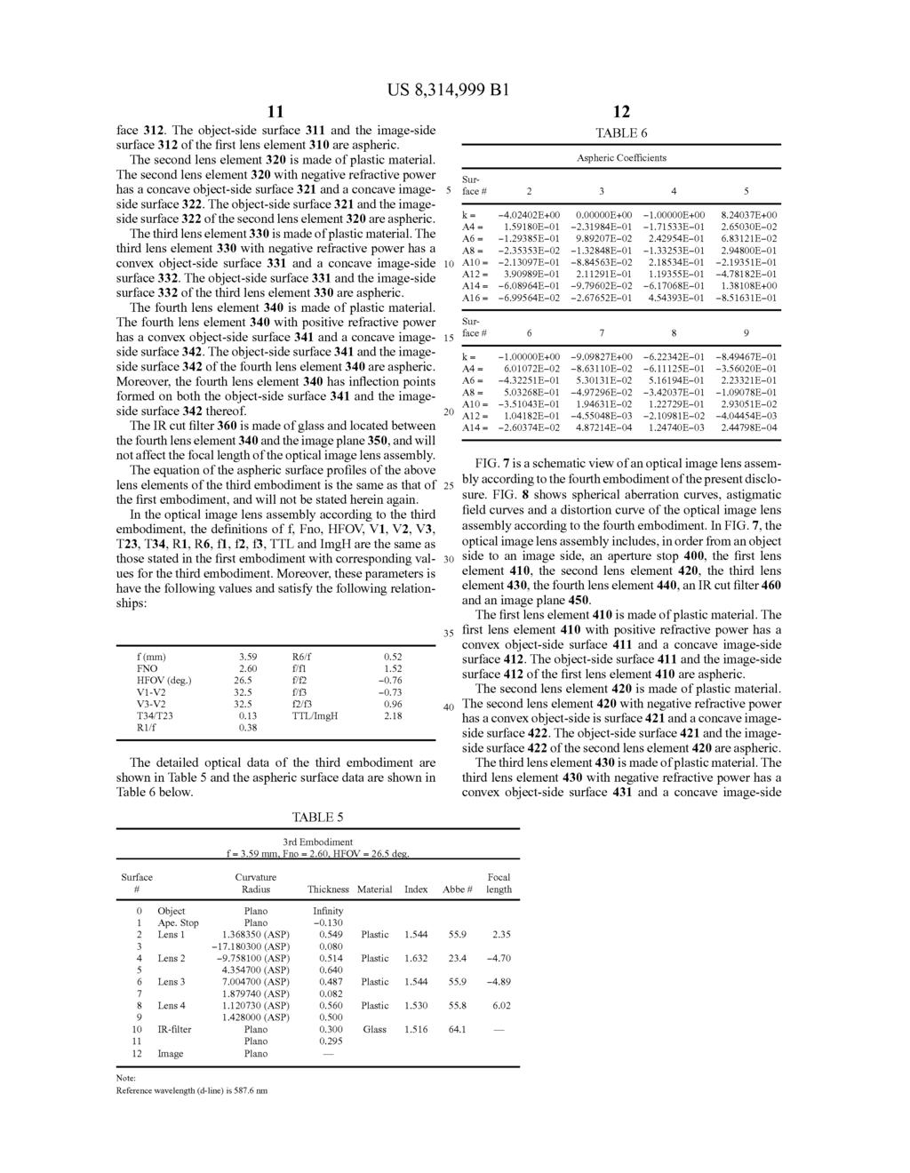
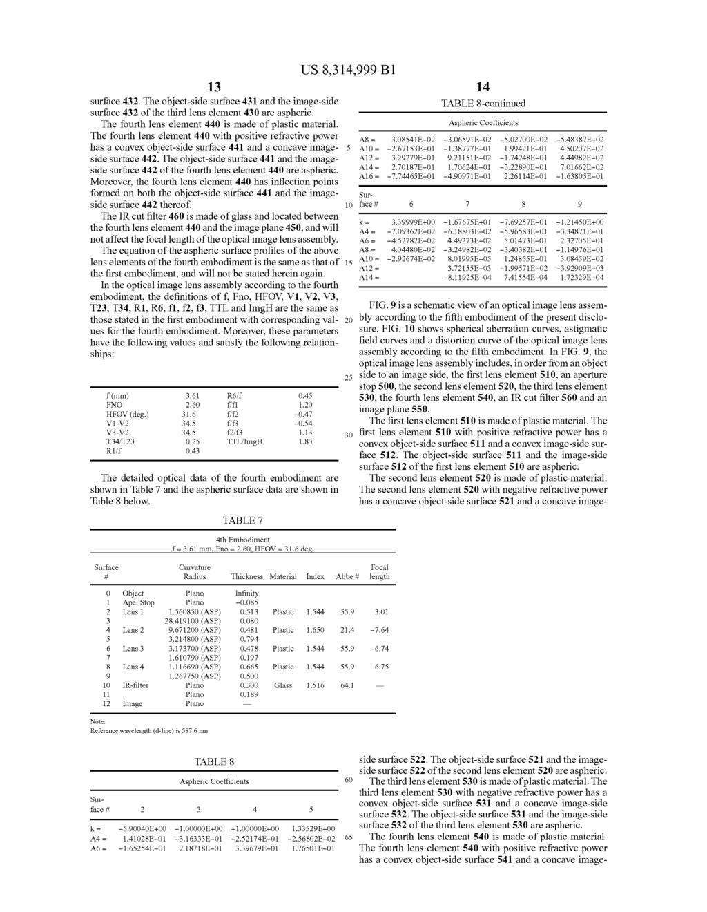
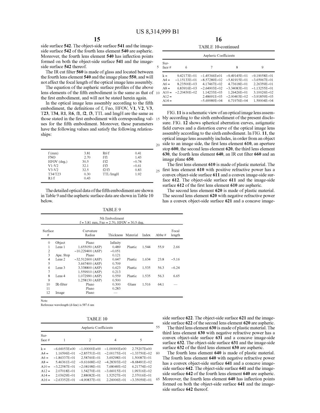
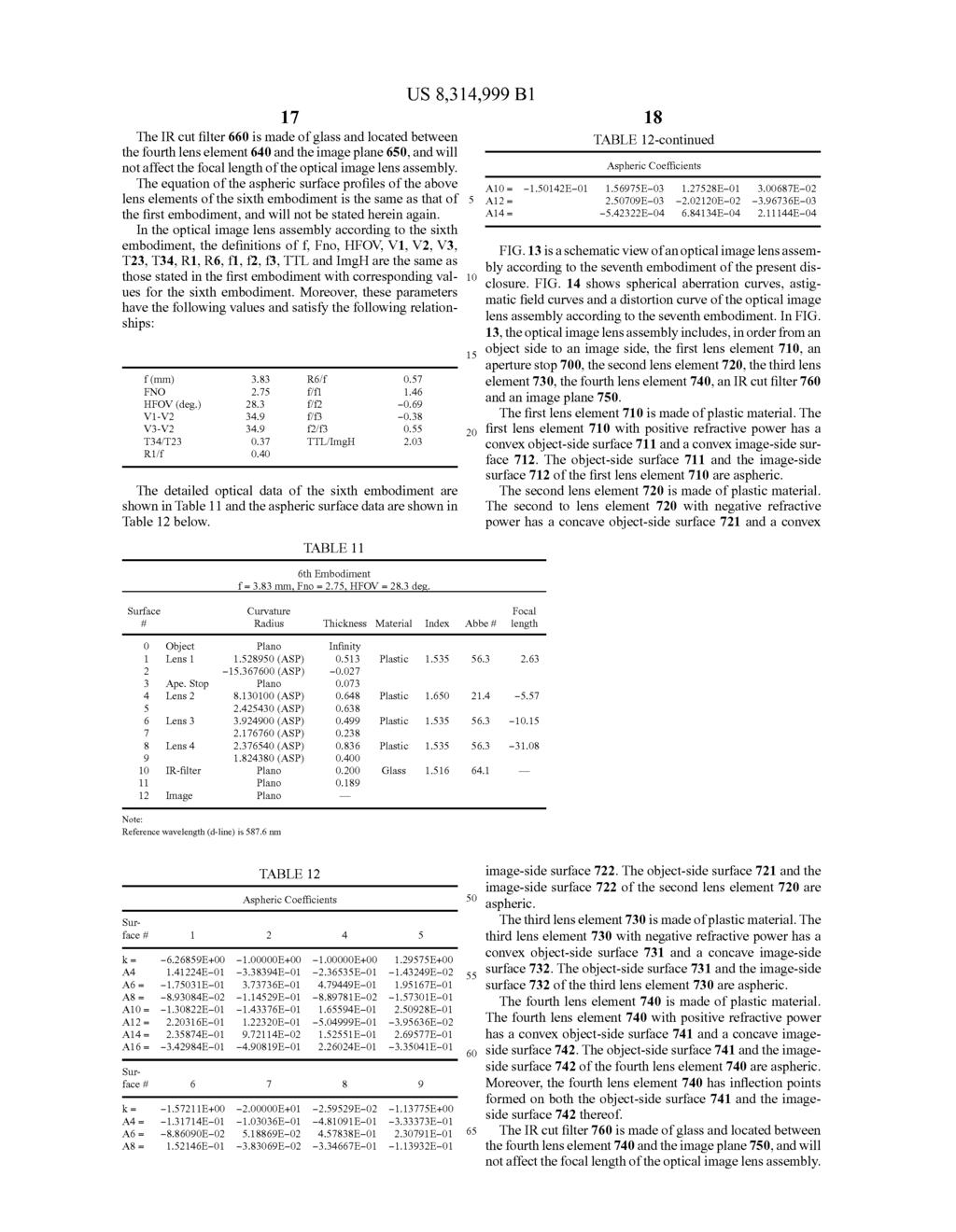
18 1 OPTICAL IMAGE LENS ASSEMBLY RELATED APPLICATIONS The application claims priority to TaiWan Application Serial Number ,?led May 16, 2011, Which is herein incorporated by reference. BACKGROUND 1. Technical Field The present invention relates to an optical image lens assembly. More particularly, the present invention relates to a compact optical image lens assembly applicable to electronic products. 2. Description of Related Art In recent years, With the popularity of mobile products With camera functionalities, the demand for compact optical image lens assemblies is increasing. The sensor of a conven tional photographing camera is typically a CCD (Charge Coupled Device) image sensor or a CMOS (Complementary Metal-Oxide-Semiconductor) sensor. As advanced semicon ductor manufacturing technologies have allowed the pixel size of sensors to be reduced and compact optical image lens assemblies have gradually evolved toward higher megapix els, there is an increasing demand for compact optical image lens assemblies featuring better image quality. A conventional compact optical image lens assembly in a portable electronic product typically utilizes a three-element lens structure. Such a conventional optical image lens assem bly has a?rst lens element With positive refractive power, a second lens element With negative refractive power and a third lens element With positive refractive power. The?rst, second and third lens elements are arranged in this order from an obj ect-side to an image-side. While the three-element lens structure is compact, it is not able to produce high quality images. Another conventional compact optical image lens assem bly provides a four-element lens structure. The?rst lens ele ment and the second lens element of the four-element lens structure are two glass spherical lens elements Which are attached to each other to form a doublet lens for eliminating chromatic aberration. HoWever, this lens structure requires a longer total optical track length caused by insuf?cient degrees of freedom in setting system parameters due to too many spherical lenses allocated. Moreover, it is not easy to attach the glass lenses, and thus the manufacturing process for form ing the glass doublet lenses is dif?cult. SUMMARY According to one aspect of the present disclosure, an opti cal image lens assembly includes, in order from an object side to an image side, a?rst lens element, a second lens element, a third lens element and a fourth lens element. The?rst lens element With positive refractive power has a convex object side surface. The second lens element has negative refractive power. The third lens element With negative refractive power has a convex object-side surface and a concave image-side surface. The third lens element is made of plastic material, and the object-side surface and the image-side surface of the third lens element are aspheric. The fourth lens element With refractive power has a concave image- side surface. The fourth lens element is made of plastic material, and the object-side surface and the image-side surface of the fourth lens element are aspheric. When an axial distance between the second lens element and the third lens element is T23, an axial distance US 8,314,999 B between the third lens element and the fourth lens element is T34, a focal length of the optical image lens assembly is f, and a focal length of the third lens element is f3, the following relationships are satis?ed: According to another aspect of the present disclosure, an optical image lens assembly includes, in order from an object side to an image side, a?rst lens element, a second lens element, a third lens element and a fourth lens element. The?rst lens element With positive refractive power has a convex object-side surface. The second lens element has negative refractive power. The third lens element With negative refrac tive power has a convex object-side surface and a concave image-side surface. The third lens element is made of plastic material and the object-side surface and the image-side sur face of the third lens element are aspheric. The fourth lens element With refractive power has a concave image-side sur face. The fourth lens element is made of plastic material and the object-side surface and the image-side surface of the fourth lens element are aspheric. When an axial distance between the second lens element and the third lens element is T23, an axial distance between the third lens element and the fourth lens element is T34, a focal length of the second lens element is f2, a focal length of the third lens element is f3, the Abbe number of the second lens element is V2, and the Abbe number of the third lens element is V3, the following rela tionships are satis?ed: BRIEF DESCRIPTION OF THE DRAWINGS FIG. 1 is a schematic view of an optical image lens assem bly according to the?rst embodiment of the present disclo sure; FIG. 2 shows spherical aberration curves, astigmatic?eld curves and a distortion curve of the optical image lens assem bly according to the?rst embodiment; FIG. 3 is a schematic view of an optical image lens assem bly according to the second embodiment of the present dis closure; FIG. 4 shows spherical aberration curves, astigmatic?eld curves and a distortion curve of the optical image lens assem bly according to the second embodiment; FIG. 5 is a schematic view of an optical image lens assem bly according to the third embodiment of the present disclo sure; FIG. 6 shows spherical aberration curves, astigmatic?eld curves and a distortion curve of the optical image lens assem bly according to the third embodiment; FIG. 7 is a schematic view of an optical image lens assem bly according to the fourth embodiment of the present disclo sure; FIG. 8 shows spherical aberration curves, astigmatic?eld curves and a distortion curve of the optical image lens assem bly according to the fourth embodiment; FIG. 9 is a schematic view of an optical image lens assem bly according to the?fth embodiment of the present disclo sure;

19 3 FIG. 10 shows spherical aberration curves, astigmatic?eld curves and a distortion curve of the optical image lens assem bly according to the?fth embodiment; FIG. 11 is a schematic view of an optical image lens assem bly according to the sixth embodiment of the present disclo sure; FIG. 12 shows spherical aberration curves, astigmatic?eld curves and a distortion curve of the optical image lens assem bly according to the sixth embodiment; FIG. 13 is a schematic view of an optical image lens assem bly according to the seventh embodiment of the present dis closure; FIG. 14 shows spherical aberration curves, astigmatic?eld curves and a distortion curve of the optical image lens assem bly according to the seventh embodiment; FIG. 15 is a schematic view of an optical image lens assem bly according to the eighth embodiment of the present dis closure; and FIG. 16 shows spherical aberration curves, astigmatic?eld curves and a distortion curve of the optical image lens assem bly according to the eighth embodiment. DETAILED DESCRIPTION An optical image lens assembly includes, in order from an object side to an image side, a?rst lens element, a second lens element, a third lens element and a fourth lens element. The optical image lens assembly further includes an image sensor located on the image plane. The?rst lens element With positive refractive power pro vides partial refractive power for reducing the total track length of the optical image lens assembly. The?rst lens ele ment has a convex obj ect-side surface, and can have a convex image-side surface or a concave image-side surface. When the?rst lens element has a convex object-side surface and a convex image-side surface, the refractive power thereof can be effectively enhanced, thus further reducing the total track length of the optical image lens assembly. When the?rst lens element has a convex object-side surface and a concave image-side surface, the astigmatism of the optical image lens assembly can be is corrected. The second lens element With negative refractive power can correct the aberration generated from the?rst lens ele ment and the chromatic aberration of the optical image lens assembly. The third lens element With negative refractive power can cooperate With the second lens element for reducing the pho tosensitivity of the optical image lens assembly. The third lens element has a convex object-side surface and a concave image-side surface so that the back focal length of the optical image lens assembly can be increased, thereby ensuring that there is a su?icient back focal length for the disposing of other elements. The fourth lens element has a concave image-side surface so that the principal point of the optical image lens assembly can be positioned away from the image plane, and the total track length of the optical image lens assembly can be reduced so as to maintain the compact size of the optical image lens assembly. The fourth lens element can have a convex obj ect-side surface for correcting the astigmatism and the high-order aberration. Furthermore, the fourth lens ele ment can have positive refractive power or negative refractive power. When the fourth lens element has positive refractive power, the high-order aberration of the optical image lens assembly can be further corrected While enhancing the resolving power thereof. When the fourth lens element has negative refractive power, the principal point of the optical US 8,314,999 B image lens assembly can be further positioned away from the image plane. Moreover, the fourth lens element has at least one in?ection point formed on at least one of the obj ect-side surface and the image-side surface thereof. Therefore, the incident angle of the off-axis?eld of light on the image sensor can be effectively minimized and the aberration of the off axis?eld can be corrected. When an axial distance between the second lens element and the third lens element is T23, and an axial distance between the third lens element and the fourth lens element is T34, the following relationship is satis?ed: Therefore, the arrangement of the third lens element can further reduce the track focal length of the optical image lens assembly. T23 and T34 can further satisfy the following rela tionship: When a focal length of the optical image lens assembly is f, and a focal length of the third lens element is f3, the following relationship is satis?ed: Therefore, the focal length of the third lens element can reduce the photo sensitivity of the optical image lens assembly effectively. f and f3 can further satisfy the following relationship: Moreover, f and 13 can further satisfy the following rela tionship: When the focal length of the second lens element is f2, and the focal length of the third lens element is f3, the following relationship is satis?ed: Therefore, the refractive power of the second lens element can be controlled for reducing the photosensitivity of the optical image lens assembly. f2 and f3 can further satisfy the following relationship: When the Abbe number of the second lens element is V2, and the Abbe number of the third lens element is V3, the following relationship is satis?ed: Therefore, the ability for correcting the chromatic aberra tion of the optical image lens assembly can be enhanced. When the focal length of the optical image lens assembly is f, and the focal length of the second lens element is f2, the following relationship is satis?ed: Therefore, the focal length of the second lens element can correct the aberration of the optical image lens assembly. When the focal length of the optical image lens assembly is f, and a focal length of the?rst lens element is f1, the follow ing relationship is satis?ed: Therefore, the total track length of the optical image lens assembly can be controlled by the refractive power of the?rst lens element, and the spherical aberration thereof can also be avoided.

20 5 When the focal length of the optical image lens assembly is f, and a curvature radius of the image- side surface of the third lens element is R6, the following relationship is satis?ed: Therefore, the curvature of the image-side surface of the third lens element can correct the astigmatism of the optical image lens assembly. When the Abbe number of the?rst lens element is V1, and the Abbe number of the second lens element is V2, the fol lowing relationship is satis?ed: Therefore, the ability for correcting the chromatic aberra tion of the optical image lens assembly can be enhanced. When a curvature radius of the object-side surface of the?rst lens element is R1, and the focal length of the optical image lens assembly is f, the following relationship is satis?ed: Therefore, the total track length of optical image lens assembly can be further reduced so as to maintain the com pact size thereof. When a half of a diagonal length of an effective photosen sitive area of the image sensor is Imgh, and an axial distance between the obj ect-side surface of the?rst lens element and the image plane is TTL, the following relationship is satis?ed: Therefore, the total track length of the optical image lens assembly can be reduced, so as to maintain the compact size of the optical image lens assembly. As a result, the optical image system may be applied to lightweight and portable electronic products. According to the optical image lens assembly of the present disclosure, When the lens element has a convex sur face, this indicates that the paraxial region of the surface is convex, and When the lens element has a concave surface, this indicates that the paraxial region of the surface is concave. According to the optical image lens assembly of the present disclosure, the lens element can be made of glass material or plastic material. When the lens element is made of glass material, the range over Which the refractive power of the optical image lens assembly can be set may be increased. When the lens element is made of plastic material, the cost of manufacture can be effectively reduced. Moreover, the sur face of the lens element can be aspheric, so that it is easier to make the surface into other non-spherical shapes. As a result, more controllable variables are obtained, the aberration is reduced and the number of required lens elements is reduced. Therefore, the total track length of the optical image lens assembly can be reduced. According to the optical image lens assembly of the present disclosure, the optical image lens assembly can include at least one stop for reducing stray light While retain ing high image quality, such as an aperture stop. Furthermore, the position of an aperture stop Within the optical image lens assembly can be arbitrarily placed in front of the entire optical image lens assembly or Within the optical image lens assem bly depending on the preference of the designer of the optical system, in order to achieve the desirable optical features or higher image quality produced from the optical image lens assembly. According to the above description of the present inven tion, the following lst-8th speci?c embodiments are provided for further explanation. US 8,314,999 B FIG. 1 is a schematic view of an optical image lens assem bly according to to the?rst embodiment of the present dis closure. FIG. 2 shows spherical aberration curves, astigmatic?eld curves and a distortion curve of the optical image lens assembly according to the?rst embodiment. In FIG. 1, the optical image lens assembly includes, in order from an object side to an image side, an aperture stop 100, the?rst lens element 110, the second lens element 120, the is third lens element 130, the fourth lens element 140, an IR (infrared) cut?lter 160 and an image plane 150. The?rst lens element 110 is made of plastic material. The?rst lens element 110 With positive refractive power has a convex obj ect-side surface 111 and a convex image-side sur face 112. The object-side surface 111 and the image-side surface 112 of the?rst lens element 110 are aspheric. The second lens element 120 is made of plastic material. The second lens element 120 With negative refractive power has a concave object-side surface 121 and a concave image side surface 122. The object-side surface 121 and the image side surface 122 of the second lens element 120 are aspheric. The third lens element 130 is made of plastic material. The third lens element 130 With negative refractive power has a convex object-side surface 131 and a concave image-side surface 132. The object-side surface 131 and the image-side surface 132 of the third lens element 130 are aspheric. The fourth lens element 140 is made of plastic material. The fourth lens element 140 With positive refractive power has a convex object-side surface 141 and a concave image side surface 142. The object-side surface 141 and the image side surface 142 of the fourth lens element 140 are aspheric. Moreover, the fourth lens element 140 has in?ection points formed on both the object-side surface 141 and the image side surface 142 thereof. The IR cut?lter 160 is made of glass and located between the fourth lens element 140 and the image plane 150, and Will not affect the focal length of the optical image lens assembly. The equation of the aspheric surface pro?les of the afore mentioned lens elements of the?rst embodiment is expressed as follows: Where: X is the height of a point on the aspheric surface spaced at a distance Y from the optical axis relative to the tangential plane at the aspheric surface vertex; Y is the distance from the point on the curve of the aspheric surface to the optical axis; R is the curvature radius of the surface of the lens element; k is the conic coe?icient; and Ai is the i-th aspheric coe?icient. In the optical image lens assembly according to the?rst embodiment, When f is a focal length of the optical image lens assembly, Fno is an f-number of the optical image lens assem bly, and HFOV is half of the maximal?eld of view, these parameters have the following values: f:3.38 mm; Fno:2.80; and HFOV:33.5 degrees. In the optical image lens assembly according to the?rst embodiment, When the Abbe number of the?rst lens element
21
22
23
24
25
26
27
28
29
(12) Patent Application Publication (10) Pub. No.: US 2013/ A1
 Patent Application Publication (10) Pub. No.: US 2013/ A1") (19) United States US 20130279021A1 (12) Patent Application Publication (10) Pub. No.: US 2013/0279021 A1 CHEN et al. (43) Pub. Date: Oct. 24, 2013 (54) OPTICAL IMAGE LENS SYSTEM Publication Classification
(19) United States US 20130279021A1 (12) Patent Application Publication (10) Pub. No.: US 2013/0279021 A1 CHEN et al. (43) Pub. Date: Oct. 24, 2013 (54) OPTICAL IMAGE LENS SYSTEM Publication Classification
(12) United States Patent
 United States Patent") USOO9146378B2 (12) United States Patent Chen et al. (54) IMAGE CAPTURING LENS ASSEMBLY, IMAGE CAPTURING DEVICE AND MOBILE TERMINAL (71) Applicant: LARGAN Precision Co., Ltd., Taichung (TW) (72) Inventors:
USOO9146378B2 (12) United States Patent Chen et al. (54) IMAGE CAPTURING LENS ASSEMBLY, IMAGE CAPTURING DEVICE AND MOBILE TERMINAL (71) Applicant: LARGAN Precision Co., Ltd., Taichung (TW) (72) Inventors:
(12) Patent Application Publication (10) Pub. No.: US 2013/ A1
 Patent Application Publication (10) Pub. No.: US 2013/ A1") (19) United States US 20130070346A1 (12) Patent Application Publication (10) Pub. No.: US 2013/0070346A1 HSU et al. (43) Pub. Date: Mar. 21, 2013 (54) OPTICAL IMAGE CAPTURING LENS (52) U.S. Cl. ASSEMBLY
(19) United States US 20130070346A1 (12) Patent Application Publication (10) Pub. No.: US 2013/0070346A1 HSU et al. (43) Pub. Date: Mar. 21, 2013 (54) OPTICAL IMAGE CAPTURING LENS (52) U.S. Cl. ASSEMBLY
(12) United States Patent
 United States Patent") USOO9726858B2 (12) United States Patent Huang (10) Patent No.: (45) Date of Patent: Aug. 8, 2017 (54) PHOTOGRAPHING OPTICAL LENS ASSEMBLY, IMAGE CAPTURING DEVICE AND ELECTRONIC DEVICE (71) Applicant: LARGAN
USOO9726858B2 (12) United States Patent Huang (10) Patent No.: (45) Date of Patent: Aug. 8, 2017 (54) PHOTOGRAPHING OPTICAL LENS ASSEMBLY, IMAGE CAPTURING DEVICE AND ELECTRONIC DEVICE (71) Applicant: LARGAN
(12) United States Patent (10) Patent No.: US 8.441,745 B2
 United States Patent (10) Patent No.: US 8.441,745 B2") USOO8441745B2 (12) United States Patent (10) Patent No.: US 8.441,745 B2 Tang et al. (45) Date of Patent: May 14, 2013 (54) OPTICAL LENS ASSEMBLY FOR IMAGE TAKING (56) References Cited U.S. PATENT DOCUMENTS
USOO8441745B2 (12) United States Patent (10) Patent No.: US 8.441,745 B2 Tang et al. (45) Date of Patent: May 14, 2013 (54) OPTICAL LENS ASSEMBLY FOR IMAGE TAKING (56) References Cited U.S. PATENT DOCUMENTS
(12) United States Patent (10) Patent No.: US 8,953,257 B1
 United States Patent (10) Patent No.: US 8,953,257 B1") US00895.3257B1 (12) United States Patent (10) Patent No.: Chen (45) Date of Patent: Feb. 10, 2015 (54) IMAGE CAPTURING LENS SYSTEMAND (56) References Cited IMAGE CAPTURING DEVICE U.S. PATENT DOCUMENTS
US00895.3257B1 (12) United States Patent (10) Patent No.: Chen (45) Date of Patent: Feb. 10, 2015 (54) IMAGE CAPTURING LENS SYSTEMAND (56) References Cited IMAGE CAPTURING DEVICE U.S. PATENT DOCUMENTS
(12) United States Patent
 United States Patent") USOO9606328B2 (12) United States Patent Chen (10) Patent No.: (45) Date of Patent: US 9,606,328 B2 Mar. 28, 2017 (54) PHOTOGRAPHING OPTICAL LENS ASSEMBLY, IMAGE CAPTURING UNIT AND ELECTRONIC DEVICE (71)
USOO9606328B2 (12) United States Patent Chen (10) Patent No.: (45) Date of Patent: US 9,606,328 B2 Mar. 28, 2017 (54) PHOTOGRAPHING OPTICAL LENS ASSEMBLY, IMAGE CAPTURING UNIT AND ELECTRONIC DEVICE (71)
(12) Patent Application Publication (10) Pub. No.: US 2015/ A1
 Patent Application Publication (10) Pub. No.: US 2015/ A1") (19) United States US 20150286032A1 (12) Patent Application Publication (10) Pub. No.: US 2015/0286032 A1 Hsueh et al. (43) Pub. Date: Oct. 8, 2015 (54) OPTICAL LENS SYSTEM, IMAGING DEVICE (52) U.S. Cl.
(19) United States US 20150286032A1 (12) Patent Application Publication (10) Pub. No.: US 2015/0286032 A1 Hsueh et al. (43) Pub. Date: Oct. 8, 2015 (54) OPTICAL LENS SYSTEM, IMAGING DEVICE (52) U.S. Cl.
(12) United States Patent
 United States Patent") USOO8385006B2 (12) United States Patent Tsai et al. (54) (75) (73) (*) (21) (22) (65) (30) (51) (52) (58) PHOTOGRAPHING OPTICAL LENS ASSEMBLY Inventors: Tsung-Han Tsai, Taichung (TW); Hsin-Hsuan Huang,
USOO8385006B2 (12) United States Patent Tsai et al. (54) (75) (73) (*) (21) (22) (65) (30) (51) (52) (58) PHOTOGRAPHING OPTICAL LENS ASSEMBLY Inventors: Tsung-Han Tsai, Taichung (TW); Hsin-Hsuan Huang,
(12) United States Patent
 United States Patent") US009 158091B2 (12) United States Patent Park et al. (10) Patent No.: (45) Date of Patent: US 9,158,091 B2 Oct. 13, 2015 (54) (71) LENS MODULE Applicant: SAMSUNGELECTRO-MECHANICS CO.,LTD., Suwon (KR) (72)
US009 158091B2 (12) United States Patent Park et al. (10) Patent No.: (45) Date of Patent: US 9,158,091 B2 Oct. 13, 2015 (54) (71) LENS MODULE Applicant: SAMSUNGELECTRO-MECHANICS CO.,LTD., Suwon (KR) (72)
(12) Patent Application Publication (10) Pub. No.: US 2007/ A1
 Patent Application Publication (10) Pub. No.: US 2007/ A1") (19) United States (12) Patent Application Publication (10) Pub. No.: US 2007/0091458 A1 Asami et al. US 20070091458A1 (43) Pub. Date: Apr. 26, 2007 (54) WIDE-ANGLE IMAGING LENS (75) Inventors: Taro Asami,
(19) United States (12) Patent Application Publication (10) Pub. No.: US 2007/0091458 A1 Asami et al. US 20070091458A1 (43) Pub. Date: Apr. 26, 2007 (54) WIDE-ANGLE IMAGING LENS (75) Inventors: Taro Asami,
(12) Patent Application Publication (10) Pub. No.: US 2016/ A1
 Patent Application Publication (10) Pub. No.: US 2016/ A1") US 201603061.41A1 (19) United States (12) Patent Application Publication (10) Pub. No.: US 2016/0306141 A1 CHEN et al. (43) Pub. Date: (54) OPTICAL LENS Publication Classification (71) Applicant: ABILITY
US 201603061.41A1 (19) United States (12) Patent Application Publication (10) Pub. No.: US 2016/0306141 A1 CHEN et al. (43) Pub. Date: (54) OPTICAL LENS Publication Classification (71) Applicant: ABILITY
( 12 ) United States Patent
 United States Patent") ( 12 ) United States Patent Hsueh et al. ( 54 ) IMAGING LENS SYSTEM, IMAGE CAPTURING UNIT AND ELECTRONIC DEVICE ( 71 ) Applicant : LARGAN Precision Co., Ltd., Taichung ( TW ) ( 72 ) Inventors : Chun Che
( 12 ) United States Patent Hsueh et al. ( 54 ) IMAGING LENS SYSTEM, IMAGE CAPTURING UNIT AND ELECTRONIC DEVICE ( 71 ) Applicant : LARGAN Precision Co., Ltd., Taichung ( TW ) ( 72 ) Inventors : Chun Che
United States Patent (19) Hirakawa
 Hirakawa") United States Patent (19) Hirakawa US005233474A 11 Patent Number: (45) Date of Patent: 5,233,474 Aug. 3, 1993 (54) WIDE-ANGLE LENS SYSTEM (75) Inventor: Jun Hirakawa, Tokyo, Japan 73) Assignee: Asahi Kogaku
United States Patent (19) Hirakawa US005233474A 11 Patent Number: (45) Date of Patent: 5,233,474 Aug. 3, 1993 (54) WIDE-ANGLE LENS SYSTEM (75) Inventor: Jun Hirakawa, Tokyo, Japan 73) Assignee: Asahi Kogaku
(12) United States Patent (10) Patent No.: US 8,437,091 B2
 United States Patent (10) Patent No.: US 8,437,091 B2") USOO8437091B2 (12) United States Patent (10) Patent No.: US 8,437,091 B2 Hsu et al. (45) Date of Patent: May 7, 2013 (54) WIDE VIEWING ANGLE OPTICAL LENS (58) Field of Classification Search... 359/642,
USOO8437091B2 (12) United States Patent (10) Patent No.: US 8,437,091 B2 Hsu et al. (45) Date of Patent: May 7, 2013 (54) WIDE VIEWING ANGLE OPTICAL LENS (58) Field of Classification Search... 359/642,
J0 (45) Date of Patent: Jan. 22, (54) PHOTOGRAPHICLENS 7, 177,098 B2 * 2/2007 Arai ,715
 Date of Patent: Jan. 22, (54) PHOTOGRAPHICLENS 7, 177,098 B2 * 2/2007 Arai ,715") (12) United States Patent USOO7321474B1 (10) Patent No.: US 7,321,474 B1 J0 (45) Date of Patent: Jan. 22, 2008 (54) PHOTOGRAPHICLENS 7, 177,098 B2 * 2/2007 Arai... 359,715 2005, 0105.194 A1* 5, 2005 Matsui
(12) United States Patent USOO7321474B1 (10) Patent No.: US 7,321,474 B1 J0 (45) Date of Patent: Jan. 22, 2008 (54) PHOTOGRAPHICLENS 7, 177,098 B2 * 2/2007 Arai... 359,715 2005, 0105.194 A1* 5, 2005 Matsui
(12) Patent Application Publication (10) Pub. No.: US 2015/ A1
 Patent Application Publication (10) Pub. No.: US 2015/ A1") (19) United States (12) Patent Application Publication (10) Pub. No.: US 2015/0103414 A1 Baik US 2015O103414A1 (43) Pub. Date: Apr. 16, 2015 (54) LENS MODULE (71) Applicant: SAMSUNGELECTRO-MECHANCS CO.,LTD.,
(19) United States (12) Patent Application Publication (10) Pub. No.: US 2015/0103414 A1 Baik US 2015O103414A1 (43) Pub. Date: Apr. 16, 2015 (54) LENS MODULE (71) Applicant: SAMSUNGELECTRO-MECHANCS CO.,LTD.,
(12) United States Patent
 United States Patent") (12) United States Patent JO et al. USOO6844989B1 (10) Patent No.: (45) Date of Patent: Jan. 18, 2005 (54) LENS SYSTEM INSTALLED IN MOBILE COMMUNICATION TERMINAL (75) Inventors: Yong-Joo Jo, Kyunggi-Do
(12) United States Patent JO et al. USOO6844989B1 (10) Patent No.: (45) Date of Patent: Jan. 18, 2005 (54) LENS SYSTEM INSTALLED IN MOBILE COMMUNICATION TERMINAL (75) Inventors: Yong-Joo Jo, Kyunggi-Do
( 12 ) Patent Application Publication ( 10 ) Pub. No.: US 2017 / A1
 Patent Application Publication ( 10 ) Pub. No.: US 2017 / A1") WILD MOVED LUONNONTON MOUNTAIN US 207027694A 9 United States ( 2 ) Patent Application Publication ( 0 ) Pub. No.: US 207 / 027694 A Yao et al. ( 43 ) Pub. Date : Sep. 28, 207 ( 54 ) FOLDED LENS SYSTEM
WILD MOVED LUONNONTON MOUNTAIN US 207027694A 9 United States ( 2 ) Patent Application Publication ( 0 ) Pub. No.: US 207 / 027694 A Yao et al. ( 43 ) Pub. Date : Sep. 28, 207 ( 54 ) FOLDED LENS SYSTEM
(12) United States Patent
 United States Patent") USOO9063318B2 (12) United States Patent Ishizaka (54) IMAGING LENS (71) Applicant: KANTATSU CO.,LTD., Yaita-shi, Tochigi (JP) (72) Inventor: Tohru Ishizaka, Sukagawa (JP) (73) Assignee: KANTATSU CO.,LTD.,
USOO9063318B2 (12) United States Patent Ishizaka (54) IMAGING LENS (71) Applicant: KANTATSU CO.,LTD., Yaita-shi, Tochigi (JP) (72) Inventor: Tohru Ishizaka, Sukagawa (JP) (73) Assignee: KANTATSU CO.,LTD.,
(12) Patent Application Publication (10) Pub. No.: US 2007/ A1
 Patent Application Publication (10) Pub. No.: US 2007/ A1") (19) United States US 20070147825A1 (12) Patent Application Publication (10) Pub. No.: US 2007/0147825 A1 Lee et al. (43) Pub. Date: Jun. 28, 2007 (54) OPTICAL LENS SYSTEM OF MOBILE Publication Classification
(19) United States US 20070147825A1 (12) Patent Application Publication (10) Pub. No.: US 2007/0147825 A1 Lee et al. (43) Pub. Date: Jun. 28, 2007 (54) OPTICAL LENS SYSTEM OF MOBILE Publication Classification
(12) Patent Application Publication (10) Pub. No.: US 2007/ A1
 Patent Application Publication (10) Pub. No.: US 2007/ A1") (19) United States (12) Patent Application Publication (10) Pub. No.: US 2007/0132875 A1 Lee et al. US 20070132875A1 (43) Pub. Date: Jun. 14, 2007 (54) (75) (73) (21) (22) (30) OPTICAL LENS SYSTEM OF MOBILE
(19) United States (12) Patent Application Publication (10) Pub. No.: US 2007/0132875 A1 Lee et al. US 20070132875A1 (43) Pub. Date: Jun. 14, 2007 (54) (75) (73) (21) (22) (30) OPTICAL LENS SYSTEM OF MOBILE
(12) Patent Application Publication (10) Pub. No.: US 2014/ A1. Yamazaki et al. (43) Pub. Date: Mar. 6, 2014
 Patent Application Publication (10) Pub. No.: US 2014/ A1. Yamazaki et al. (43) Pub. Date: Mar. 6, 2014") (19) United States US 20140063323A1 (12) Patent Application Publication (10) Pub. No.: US 2014/0063323 A1 Yamazaki et al. (43) Pub. Date: Mar. 6, 2014 (54) IMAGE PICKUP LENS AND IMAGE PICKUP (52) U.S.
(19) United States US 20140063323A1 (12) Patent Application Publication (10) Pub. No.: US 2014/0063323 A1 Yamazaki et al. (43) Pub. Date: Mar. 6, 2014 (54) IMAGE PICKUP LENS AND IMAGE PICKUP (52) U.S.
United States Statutory Invention Registration (19) Feb. 28, 1996 JP Japan (51) Int. Cl... GO2B 21/ U.S. Cl...
 Feb. 28, 1996 JP Japan (51) Int. Cl... GO2B 21/ U.S. Cl...") USOO4(OO1763B2 United States Statutory Invention Registration (19) Mizusawa 54) MICROSCOPE OBJECTIVE LENS 75 Inventor: Masayuki Mizusawa, Yokohama, Japan 73 Assignee: Nikon Corporation, Tokyo, Japan 21
USOO4(OO1763B2 United States Statutory Invention Registration (19) Mizusawa 54) MICROSCOPE OBJECTIVE LENS 75 Inventor: Masayuki Mizusawa, Yokohama, Japan 73 Assignee: Nikon Corporation, Tokyo, Japan 21
(12) Patent Application Publication (10) Pub. No.: US 2008/ A1
 Patent Application Publication (10) Pub. No.: US 2008/ A1") (19) United States US 200801 06809A1 (12) Patent Application Publication (10) Pub. No.: US 2008/0106809 A1 HIRANO (43) Pub. Date: (54) WIDE-ANGLE LENS SYSTEM (75) Inventor: Hiroyuki HIRANO, Kanagawa (JP)
(19) United States US 200801 06809A1 (12) Patent Application Publication (10) Pub. No.: US 2008/0106809 A1 HIRANO (43) Pub. Date: (54) WIDE-ANGLE LENS SYSTEM (75) Inventor: Hiroyuki HIRANO, Kanagawa (JP)
SW Š. United States Patent (19. Mercado. Mar. 19, 1991 SVS2 ANI-III ,000,548. WAC SaSas. (11) Patent Number: (45) Date of Patent:
 Patent Number: (45) Date of Patent:") United States Patent (19. Mercado (11) Patent Number: (45) Date of Patent: Mar. 19, 1991 (54) MICROSCOPE OBJECTIVE 75 Inventor: Romeo I. Mercado, San Jose, Calif. (73) Assignee: Lockheed Missiles & Space
United States Patent (19. Mercado (11) Patent Number: (45) Date of Patent: Mar. 19, 1991 (54) MICROSCOPE OBJECTIVE 75 Inventor: Romeo I. Mercado, San Jose, Calif. (73) Assignee: Lockheed Missiles & Space
Imaging Systems for Eyeglass-Based Display Devices
 University of Central Florida UCF Patents Patent Imaging Systems for Eyeglass-Based Display Devices 6-28-2011 Jannick Rolland University of Central Florida Ozan Cakmakci University of Central Florida Find
78r9 for 1234,516. United States Patent (19) 2345 ro. 11) 4,266,860 (45) May 12, Hayashi. taining an excellent image-forming performance em
 2345 ro. 11) 4,266,860 (45) May 12, Hayashi. taining an excellent image-forming performance em") 5/12/8 OR war v Y 4, 266 860 United States Patent (19) Hayashi 54 WIDE ANGLE ZOOM LENS SYSTEM HAVING SHORTENED CLOSEUP FOCAL LENGTH (75) Inventor: Kiyoshi Hayashi, Yokohama, Japan 73) Assignee: Nippon
5/12/8 OR war v Y 4, 266 860 United States Patent (19) Hayashi 54 WIDE ANGLE ZOOM LENS SYSTEM HAVING SHORTENED CLOSEUP FOCAL LENGTH (75) Inventor: Kiyoshi Hayashi, Yokohama, Japan 73) Assignee: Nippon
don, G.B. U.S. P. DOCUMENTS spaced by an air gap from the collecting lens. The widths of
 United States Patent (19) Wartmann III US005708532A 11 Patent Number: 5,708,532 45 Date of Patent: Jan. 13, 1998 (54) DOUBLE-SIDED TELECENTRC 573790 11/1977 U.S.S.R... 359/663 MEASUREMENT OBJECTIVE 1 248
(12) United States Patent (10) Patent No.: US 9.223,118 B2
 United States Patent (10) Patent No.: US 9.223,118 B2") USOO9223118B2 (12) United States Patent (10) Patent No.: US 9.223,118 B2 Mercado (45) Date of Patent: Dec. 29, 2015 (54) SMALL FORM FACTOR TELEPHOTO 7,502,181 B2 3/2009 Shinohara CAMERA 7,554,597 B2 6,
USOO9223118B2 (12) United States Patent (10) Patent No.: US 9.223,118 B2 Mercado (45) Date of Patent: Dec. 29, 2015 (54) SMALL FORM FACTOR TELEPHOTO 7,502,181 B2 3/2009 Shinohara CAMERA 7,554,597 B2 6,
United States Patent 19
 United States Patent 19 Kohayakawa 54) OCULAR LENS MEASURINGAPPARATUS (75) Inventor: Yoshimi Kohayakawa, Yokohama, Japan 73 Assignee: Canon Kabushiki Kaisha, Tokyo, Japan (21) Appl. No.: 544,486 (22 Filed:
202 19' 19 19' (12) United States Patent 202' US 7,050,043 B2. Huang et al. May 23, (45) Date of Patent: (10) Patent No.
 United States Patent 202' US 7,050,043 B2. Huang et al. May 23, (45) Date of Patent: (10) Patent No.") US00705.0043B2 (12) United States Patent Huang et al. (10) Patent No.: (45) Date of Patent: US 7,050,043 B2 May 23, 2006 (54) (75) (73) (*) (21) (22) (65) (30) Foreign Application Priority Data Sep. 2,
US00705.0043B2 (12) United States Patent Huang et al. (10) Patent No.: (45) Date of Patent: US 7,050,043 B2 May 23, 2006 (54) (75) (73) (*) (21) (22) (65) (30) Foreign Application Priority Data Sep. 2,
(12) United States Patent
 United States Patent") USO08035723B2 (12) United States Patent Sano et al. (10) Patent No.: (45) Date of Patent: US 8,035,723 B2 Oct. 11, 2011 (54) IMAGE PICKUP LENS, IMAGE PICKUP APPARATUS AND MOBILE TERMINAL (75) Inventors:
USO08035723B2 (12) United States Patent Sano et al. (10) Patent No.: (45) Date of Patent: US 8,035,723 B2 Oct. 11, 2011 (54) IMAGE PICKUP LENS, IMAGE PICKUP APPARATUS AND MOBILE TERMINAL (75) Inventors:
(12) United States Patent
 United States Patent") USOO9563 041B2 (12) United States Patent Kawaguchi et al. (10) Patent No.: (45) Date of Patent: US 9,563,041 B2 Feb. 7, 2017 (54) OPTICAL SYSTEM FOR AN INFRARED RAY (71) Applicant: Tamron Co., Ltd., Saitama-shi
USOO9563 041B2 (12) United States Patent Kawaguchi et al. (10) Patent No.: (45) Date of Patent: US 9,563,041 B2 Feb. 7, 2017 (54) OPTICAL SYSTEM FOR AN INFRARED RAY (71) Applicant: Tamron Co., Ltd., Saitama-shi
USOO A United States Patent (19) 11 Patent Number: 5,877,901 Enomoto et al. (45) Date of Patent: Mar. 2, 1999
 11 Patent Number: 5,877,901 Enomoto et al. (45) Date of Patent: Mar. 2, 1999") USOO5877901A United States Patent (19) 11 Patent Number: Enomoto et al. (45) Date of Patent: Mar. 2, 1999 54 SUPER WIDE-ANGLE ZOOM LENS 4,844,599 7/1989 Ito. 4,934,797 6/1990 Hirakawa. 75 Inventors: Takashi
USOO5877901A United States Patent (19) 11 Patent Number: Enomoto et al. (45) Date of Patent: Mar. 2, 1999 54 SUPER WIDE-ANGLE ZOOM LENS 4,844,599 7/1989 Ito. 4,934,797 6/1990 Hirakawa. 75 Inventors: Takashi
O R 4,720, 1 R 5... United States talent (19) (11 Patent Number; 4,720,183 Dilworth (45) Date of Patent: Jan. 19, 1988
 (11 Patent Number; 4,720,183 Dilworth (45) Date of Patent: Jan. 19, 1988") O R 4,720, 1 R 5..... United States talent (19) (11 Patent Number; 4,720,183 Dilworth (45) Date of Patent: Jan. 19, 1988 54 EXTREME wrde ANGLEEYEPIECE WITH (56) References Cited - MN MALABERRATIONS. U.S.
O R 4,720, 1 R 5..... United States talent (19) (11 Patent Number; 4,720,183 Dilworth (45) Date of Patent: Jan. 19, 1988 54 EXTREME wrde ANGLEEYEPIECE WITH (56) References Cited - MN MALABERRATIONS. U.S.
United States Patent (19)
") United States Patent (19) Muchel 54) OPTICAL SYSTEM OF WARIABLE FOCAL AND BACK-FOCAL LENGTH (75) Inventor: Franz Muchel, Königsbronn, Fed. Rep. of Germany 73 Assignee: Carl-Zeiss-Stiftung, Heidenheim on
United States Patent (19) Muchel 54) OPTICAL SYSTEM OF WARIABLE FOCAL AND BACK-FOCAL LENGTH (75) Inventor: Franz Muchel, Königsbronn, Fed. Rep. of Germany 73 Assignee: Carl-Zeiss-Stiftung, Heidenheim on
Waves & Oscillations
 Physics 42200 Waves & Oscillations Lecture 33 Geometric Optics Spring 2013 Semester Matthew Jones Aberrations We have continued to make approximations: Paraxial rays Spherical lenses Index of refraction
350 a 439 SR x V y (2) slril V -2- OR 3,524,697 - the OS, 0. Aug. 18, 1970 MASAK SSH K ET AL 3,524,697 ACHROMATIC SUPER WIDE-ANGLE LENS
 slril V -2- OR 3,524,697 - the OS, 0. Aug. 18, 1970 MASAK SSH K ET AL 3,524,697 ACHROMATIC SUPER WIDE-ANGLE LENS") 350 a 439 SR x V y (2) slril V -2- OR - the OS, 0 Aug. 18, 1970 MASAK SSH K ET AL Filed April 23, 1968 2 Sleets-Sheet l F G. Li L-2-3-4-5L6 L7-8 l LiO d7de di-, d2 4. ) -- d2 d\ds iy INA dis r s 58 9 of
350 a 439 SR x V y (2) slril V -2- OR - the OS, 0 Aug. 18, 1970 MASAK SSH K ET AL Filed April 23, 1968 2 Sleets-Sheet l F G. Li L-2-3-4-5L6 L7-8 l LiO d7de di-, d2 4. ) -- d2 d\ds iy INA dis r s 58 9 of
(12) Patent Application Publication (10) Pub. No.: US 2002/ A1
 Patent Application Publication (10) Pub. No.: US 2002/ A1") (19) United States US 20020O24744A1 (12) Patent Application Publication (10) Pub. No. US 2002/0024744 A1 Kasahara (43) Pub. Date Feb. 28, 2002 (54) MICROSCOPE OBJECTIVE LENS (76) Inventor Takashi Kasahara,
(19) United States US 20020O24744A1 (12) Patent Application Publication (10) Pub. No. US 2002/0024744 A1 Kasahara (43) Pub. Date Feb. 28, 2002 (54) MICROSCOPE OBJECTIVE LENS (76) Inventor Takashi Kasahara,
(12) United States Patent
 United States Patent") (12) United States Patent US007.961391 B2 (10) Patent No.: US 7.961,391 B2 Hua (45) Date of Patent: Jun. 14, 2011 (54) FREE SPACE ISOLATOR OPTICAL ELEMENT FIXTURE (56) References Cited U.S. PATENT DOCUMENTS
(12) United States Patent US007.961391 B2 (10) Patent No.: US 7.961,391 B2 Hua (45) Date of Patent: Jun. 14, 2011 (54) FREE SPACE ISOLATOR OPTICAL ELEMENT FIXTURE (56) References Cited U.S. PATENT DOCUMENTS
(12) Patent Application Publication (10) Pub. No.: US 2017/ A1. Shinohara (43) Pub. Date: Apr. 27, 2017
 Patent Application Publication (10) Pub. No.: US 2017/ A1. Shinohara (43) Pub. Date: Apr. 27, 2017") US 201701 15471A1 (19) United States (12) Patent Application Publication (10) Pub. No.: US 2017/0115471 A1 Shinohara (43) Pub. Date: Apr. 27, 2017 (54) LENS SYSTEM (52) U.S. Cl. CPC... G02B 13/0045 (2013.01);
US 201701 15471A1 (19) United States (12) Patent Application Publication (10) Pub. No.: US 2017/0115471 A1 Shinohara (43) Pub. Date: Apr. 27, 2017 (54) LENS SYSTEM (52) U.S. Cl. CPC... G02B 13/0045 (2013.01);
11 Patent Number: 5,331,470 Cook 45 Date of Patent: Jul. 19, ) Inventor: Lacy G. Cook, El Segundo, Calif. Assistant Examiner-James A.
 Inventor: Lacy G. Cook, El Segundo, Calif. Assistant Examiner-James A.") United States Patent (19) IIIHIIII USOO33147OA 11 Patent Number: Cook 4 Date of Patent: Jul. 19, 1994 4 FAST FOLDED WIDE ANGLE LARGE,170,284 12/1992 Cook... 39/861 RE UNOBSCURED SYSTEM Primary Examiner-Edward
United States Patent (19) IIIHIIII USOO33147OA 11 Patent Number: Cook 4 Date of Patent: Jul. 19, 1994 4 FAST FOLDED WIDE ANGLE LARGE,170,284 12/1992 Cook... 39/861 RE UNOBSCURED SYSTEM Primary Examiner-Edward
Oct RETROFOCUS-TYPE WIDE-ANGLE CAMERA LENS Original Filed Dec. 24, 1969
 3 on 460 - SR OR RE Oct. 30 773 RETROFOCUS-TYPE WIDE-ANGLE CAMERA LENS Original Filed Dec. 24, 1969 Re. Li L2 L3 F.G. n STOP -4. L6 \ ) - d d2 d6 d7 dio d5 da del d1 na 7 R rt a?g 10 r -7 L8 L9 \ 2, 5
Ch 24. Geometric Optics
 text concept Ch 24. Geometric Optics Fig. 24 3 A point source of light P and its image P, in a plane mirror. Angle of incidence =angle of reflection. text. Fig. 24 4 The blue dashed line through object
(12) United States Patent (10) Patent No.: US 6,750,955 B1
 United States Patent (10) Patent No.: US 6,750,955 B1") USOO6750955B1 (12) United States Patent (10) Patent No.: US 6,750,955 B1 Feng (45) Date of Patent: Jun. 15, 2004 (54) COMPACT OPTICAL FINGERPRINT 5,650,842 A 7/1997 Maase et al.... 356/71 SENSOR AND METHOD
USOO6750955B1 (12) United States Patent (10) Patent No.: US 6,750,955 B1 Feng (45) Date of Patent: Jun. 15, 2004 (54) COMPACT OPTICAL FINGERPRINT 5,650,842 A 7/1997 Maase et al.... 356/71 SENSOR AND METHOD
United States Patent (19)
") 4 a c (, 42 R 6. A 7 United States Patent (19) Sprague et al. 11 (45) 4,428,647 Jan. 31, 1984 (54) MULTI-BEAM OPTICAL SYSTEM USING LENS ARRAY (75. Inventors: Robert A. Sprague, Saratoga; Donald R. Scifres,
4 a c (, 42 R 6. A 7 United States Patent (19) Sprague et al. 11 (45) 4,428,647 Jan. 31, 1984 (54) MULTI-BEAM OPTICAL SYSTEM USING LENS ARRAY (75. Inventors: Robert A. Sprague, Saratoga; Donald R. Scifres,
Astronomy 80 B: Light. Lecture 9: curved mirrors, lenses, aberrations 29 April 2003 Jerry Nelson
 Astronomy 80 B: Light Lecture 9: curved mirrors, lenses, aberrations 29 April 2003 Jerry Nelson Sensitive Countries LLNL field trip 2003 April 29 80B-Light 2 Topics for Today Optical illusion Reflections
United States Patent 19) 11 Patent Number: 5,442,436 Lawson (45) Date of Patent: Aug. 15, 1995
 11 Patent Number: 5,442,436 Lawson (45) Date of Patent: Aug. 15, 1995") I () US005442436A United States Patent 19) 11 Patent Number: Lawson (45) Date of Patent: Aug. 15, 1995 54 REFLECTIVE COLLIMATOR 4,109,304 8/1978 Khvalovsky et al.... 362/259 4,196,461 4/1980 Geary......
I () US005442436A United States Patent 19) 11 Patent Number: Lawson (45) Date of Patent: Aug. 15, 1995 54 REFLECTIVE COLLIMATOR 4,109,304 8/1978 Khvalovsky et al.... 362/259 4,196,461 4/1980 Geary......
United States Patent (19) Powell
 Powell") United States Patent (19) Powell 54) LINEAR DEIVERGING LENS 75) Inventor: Ian Powell, Gloucester, Canada 73 Assignee: Canadian Patents and Development Limited, Ottawa, Canada 21 Appl. No.: 8,830 22 Filed:
United States Patent (19) Powell 54) LINEAR DEIVERGING LENS 75) Inventor: Ian Powell, Gloucester, Canada 73 Assignee: Canadian Patents and Development Limited, Ottawa, Canada 21 Appl. No.: 8,830 22 Filed:
Converging Lenses. Parallel rays are brought to a focus by a converging lens (one that is thicker in the center than it is at the edge).
.") Chapter 30: Lenses Types of Lenses Piece of glass or transparent material that bends parallel rays of light so they cross and form an image Two types: Converging Diverging Converging Lenses Parallel rays
Chapter 30: Lenses Types of Lenses Piece of glass or transparent material that bends parallel rays of light so they cross and form an image Two types: Converging Diverging Converging Lenses Parallel rays
(12) United States Patent (10) Patent No.: US 6,791,072 B1. Prabhu (45) Date of Patent: Sep. 14, 2004
 United States Patent (10) Patent No.: US 6,791,072 B1. Prabhu (45) Date of Patent: Sep. 14, 2004") USOO6791072B1 (12) United States Patent (10) Patent No.: US 6,791,072 B1 Prabhu (45) Date of Patent: Sep. 14, 2004 (54) METHOD AND APPARATUS FOR FORMING 2001/0020671 A1 * 9/2001 Ansorge et al.... 250/208.1
USOO6791072B1 (12) United States Patent (10) Patent No.: US 6,791,072 B1 Prabhu (45) Date of Patent: Sep. 14, 2004 (54) METHOD AND APPARATUS FOR FORMING 2001/0020671 A1 * 9/2001 Ansorge et al.... 250/208.1
 Telecentric Imaging Object space telecentricity stop source: edmund optics The 5 classical Seidel Aberrations First order aberrations Spherical Aberration (~r 4 ) Origin: different focal lengths for different
United States Patent (19) Miller
 Miller") M5 f 85 OR 4 55 O 58 United States Patent (19) Miller (54) (76) FISH EYE LENS SYSTEM Inventor: Rolf Miller, Wienerstr. 3, 7888 Rheinfelden, Fed. Rep. of Germany 1 Appl. No.: 379,76 Filed: May 19, 198 (30)
M5 f 85 OR 4 55 O 58 United States Patent (19) Miller (54) (76) FISH EYE LENS SYSTEM Inventor: Rolf Miller, Wienerstr. 3, 7888 Rheinfelden, Fed. Rep. of Germany 1 Appl. No.: 379,76 Filed: May 19, 198 (30)
(12) United States Patent (10) Patent No.: US 7.684,688 B2
 United States Patent (10) Patent No.: US 7.684,688 B2") USOO7684688B2 (12) United States Patent (10) Patent No.: US 7.684,688 B2 Torvinen (45) Date of Patent: Mar. 23, 2010 (54) ADJUSTABLE DEPTH OF FIELD 6,308,015 B1 * 10/2001 Matsumoto... 396,89 7,221,863
USOO7684688B2 (12) United States Patent (10) Patent No.: US 7.684,688 B2 Torvinen (45) Date of Patent: Mar. 23, 2010 (54) ADJUSTABLE DEPTH OF FIELD 6,308,015 B1 * 10/2001 Matsumoto... 396,89 7,221,863
(12) Patent Application Publication (10) Pub. No.: US 2002/ A1
 Patent Application Publication (10) Pub. No.: US 2002/ A1") (19) United States US 2002O180938A1 (12) Patent Application Publication (10) Pub. No.: US 2002/0180938A1 BOk (43) Pub. Date: Dec. 5, 2002 (54) COOLINGAPPARATUS OF COLOR WHEEL OF PROJECTOR (75) Inventor:
(19) United States US 2002O180938A1 (12) Patent Application Publication (10) Pub. No.: US 2002/0180938A1 BOk (43) Pub. Date: Dec. 5, 2002 (54) COOLINGAPPARATUS OF COLOR WHEEL OF PROJECTOR (75) Inventor:
4,162,827. United Stat to XR 49162,827. U.S. PATENT DOCUMENTS 1,293,086 2/1919 Graf /234. Jul. 31, Assignee:
 3S() a 483 SR XR 49162,827 United Stat to 11 de- Jul. 31, 1979 54 WIDE ANGLE OBJECTIVE FOR OPHTHALMOSCOPIC INSTRUMENT Yuji Ito, Chigasaki, Japan Canon Kabushiki Kaisha, Tokyo, Japan Appl. No.: 802,877
(12) United States Patent (10) Patent No.: US 9,449,544 B2
 United States Patent (10) Patent No.: US 9,449,544 B2") USOO9449544B2 (12) United States Patent () Patent No.: Duan et al. (45) Date of Patent: Sep. 20, 2016 (54) AMOLED PIXEL CIRCUIT AND DRIVING (58) Field of Classification Search METHOD CPC... A01B 12/006;
USOO9449544B2 (12) United States Patent () Patent No.: Duan et al. (45) Date of Patent: Sep. 20, 2016 (54) AMOLED PIXEL CIRCUIT AND DRIVING (58) Field of Classification Search METHOD CPC... A01B 12/006;
Performance Factors. Technical Assistance. Fundamental Optics
 Performance Factors After paraxial formulas have been used to select values for component focal length(s) and diameter(s), the final step is to select actual lenses. As in any engineering problem, this
United States Patent (19) 11) Patent Number: 5,621,555 Park (45) Date of Patent: Apr. 15, 1997 LLP 57)
 11) Patent Number: 5,621,555 Park (45) Date of Patent: Apr. 15, 1997 LLP 57)") III US005621555A United States Patent (19) 11) Patent Number: 5,621,555 Park (45) Date of Patent: Apr. 15, 1997 (54) LIQUID CRYSTAL DISPLAY HAVING 5,331,447 7/1994 Someya et al.... 359/59 REDUNDANT PXEL
III US005621555A United States Patent (19) 11) Patent Number: 5,621,555 Park (45) Date of Patent: Apr. 15, 1997 (54) LIQUID CRYSTAL DISPLAY HAVING 5,331,447 7/1994 Someya et al.... 359/59 REDUNDANT PXEL
(12) United States Patent
 United States Patent") (12) United States Patent Waibel et al. USOO6624881B2 (10) Patent No.: (45) Date of Patent: Sep. 23, 2003 (54) OPTOELECTRONIC LASER DISTANCE MEASURING INSTRUMENT (75) Inventors: Reinhard Waibel, Berneck
(12) United States Patent Waibel et al. USOO6624881B2 (10) Patent No.: (45) Date of Patent: Sep. 23, 2003 (54) OPTOELECTRONIC LASER DISTANCE MEASURING INSTRUMENT (75) Inventors: Reinhard Waibel, Berneck
(12) Patent Application Publication (10) Pub. No.: US 2006/ A1
 Patent Application Publication (10) Pub. No.: US 2006/ A1") US 2006O171041A1 (19) United States (12) Patent Application Publication (10) Pub. No.: US 2006/0171041 A1 Olmstead et al. (43) Pub. Date: Aug. 3, 2006 (54) EXTENDED DEPTH OF FIELD IMAGING (52) U.S. Cl....
US 2006O171041A1 (19) United States (12) Patent Application Publication (10) Pub. No.: US 2006/0171041 A1 Olmstead et al. (43) Pub. Date: Aug. 3, 2006 (54) EXTENDED DEPTH OF FIELD IMAGING (52) U.S. Cl....
IMAGE SENSOR SOLUTIONS. KAC-96-1/5" Lens Kit. KODAK KAC-96-1/5" Lens Kit. for use with the KODAK CMOS Image Sensors. November 2004 Revision 2
 KODAK for use with the KODAK CMOS Image Sensors November 2004 Revision 2 1.1 Introduction Choosing the right lens is a critical aspect of designing an imaging system. Typically the trade off between image
(12) United States Patent
 United States Patent") (12) United States Patent Takekuma USOO6850001B2 (10) Patent No.: (45) Date of Patent: Feb. 1, 2005 (54) LIGHT EMITTING DIODE (75) Inventor: Akira Takekuma, Tokyo (JP) (73) Assignee: Agilent Technologies,
(12) United States Patent Takekuma USOO6850001B2 (10) Patent No.: (45) Date of Patent: Feb. 1, 2005 (54) LIGHT EMITTING DIODE (75) Inventor: Akira Takekuma, Tokyo (JP) (73) Assignee: Agilent Technologies,
USOO A United States Patent (19) 11 Patent Number: 5, Mercado (45) Date of Patent: Jan. 5, 1999
 11 Patent Number: 5, Mercado (45) Date of Patent: Jan. 5, 1999") USOO5856884A United States Patent (19) 11 Patent Number: Mercado (45) Date of Patent: Jan. 5, 1999 54 PROJECTION LENS SYSTEMS 4,976,525 12/1990 Matsumura et al.... 350/432 5,237,367 8/1993 Kudo... 355/67
USOO5856884A United States Patent (19) 11 Patent Number: Mercado (45) Date of Patent: Jan. 5, 1999 54 PROJECTION LENS SYSTEMS 4,976,525 12/1990 Matsumura et al.... 350/432 5,237,367 8/1993 Kudo... 355/67
Image Formation. Light from distant things. Geometrical optics. Pinhole camera. Chapter 36
 Light from distant things Chapter 36 We learn about a distant thing from the light it generates or redirects. The lenses in our eyes create images of objects our brains can process. This chapter concerns
COURSE NAME: PHOTOGRAPHY AND AUDIO VISUAL PRODUCTION (VOCATIONAL) FOR UNDER GRADUATE (FIRST YEAR)
 FOR UNDER GRADUATE (FIRST YEAR)") COURSE NAME: PHOTOGRAPHY AND AUDIO VISUAL PRODUCTION (VOCATIONAL) FOR UNDER GRADUATE (FIRST YEAR) PAPER TITLE: BASIC PHOTOGRAPHIC UNIT - 3 : SIMPLE LENS TOPIC: LENS PROPERTIES AND DEFECTS OBJECTIVES By
COURSE NAME: PHOTOGRAPHY AND AUDIO VISUAL PRODUCTION (VOCATIONAL) FOR UNDER GRADUATE (FIRST YEAR) PAPER TITLE: BASIC PHOTOGRAPHIC UNIT - 3 : SIMPLE LENS TOPIC: LENS PROPERTIES AND DEFECTS OBJECTIVES By
United States Patent 19 Reno
 United States Patent 19 Reno 11 Patent Number: 45 Date of Patent: May 28, 1985 (54) BEAM EXPANSION AND RELAY OPTICS FOR LASER DODE ARRAY 75 Inventor: Charles W. Reno, Cherry Hill, N.J. 73 Assignee: RCA
(12) United States Patent (10) Patent No.: US 6,614,995 B2
 United States Patent (10) Patent No.: US 6,614,995 B2") USOO6614995B2 (12) United States Patent (10) Patent No.: Tseng (45) Date of Patent: Sep. 2, 2003 (54) APPARATUS AND METHOD FOR COMPENSATING AUTO-FOCUS OF IMAGE 6.259.862 B1 * 7/2001 Marino et al.... 396/106
USOO6614995B2 (12) United States Patent (10) Patent No.: Tseng (45) Date of Patent: Sep. 2, 2003 (54) APPARATUS AND METHOD FOR COMPENSATING AUTO-FOCUS OF IMAGE 6.259.862 B1 * 7/2001 Marino et al.... 396/106
(12) Patent Application Publication (10) Pub. No.: US 2010/ A1
 Patent Application Publication (10) Pub. No.: US 2010/ A1") (19) United States US 20100176538A1 (12) Patent Application Publication (10) Pub. No.: US 2010/0176538A1 NOZaWa et al. (43) Pub. Date: Jul. 15, 2010 (54) SYSTEMS AND METHODS OF INSTALLING HOOK FASTENERELEMENTS
(19) United States US 20100176538A1 (12) Patent Application Publication (10) Pub. No.: US 2010/0176538A1 NOZaWa et al. (43) Pub. Date: Jul. 15, 2010 (54) SYSTEMS AND METHODS OF INSTALLING HOOK FASTENERELEMENTS
(12) Patent Application Publication (10) Pub. No.: US 2009/ A1. Yoshizawa et al. (43) Pub. Date: Mar. 5, 2009
 Patent Application Publication (10) Pub. No.: US 2009/ A1. Yoshizawa et al. (43) Pub. Date: Mar. 5, 2009") (19) United States US 20090059759A1 (12) Patent Application Publication (10) Pub. No.: US 2009/0059759 A1 Yoshizawa et al. (43) Pub. Date: Mar. 5, 2009 (54) TRANSMISSIVE OPTICAL RECORDING (22) Filed: Apr.
(19) United States US 20090059759A1 (12) Patent Application Publication (10) Pub. No.: US 2009/0059759 A1 Yoshizawa et al. (43) Pub. Date: Mar. 5, 2009 (54) TRANSMISSIVE OPTICAL RECORDING (22) Filed: Apr.
(12) Patent Application Publication (10) Pub. No.: US 2008/ A1. Kalevo (43) Pub. Date: Mar. 27, 2008
 Patent Application Publication (10) Pub. No.: US 2008/ A1. Kalevo (43) Pub. Date: Mar. 27, 2008") US 2008.0075354A1 (19) United States (12) Patent Application Publication (10) Pub. No.: US 2008/0075354 A1 Kalevo (43) Pub. Date: (54) REMOVING SINGLET AND COUPLET (22) Filed: Sep. 25, 2006 DEFECTS FROM
US 2008.0075354A1 (19) United States (12) Patent Application Publication (10) Pub. No.: US 2008/0075354 A1 Kalevo (43) Pub. Date: (54) REMOVING SINGLET AND COUPLET (22) Filed: Sep. 25, 2006 DEFECTS FROM
US 9,470,887 B2. Oct. 18, (45) Date of Patent: (10) Patent No.: Tsai et al. disc is suitable for rotating with respect to an axis.
 Date of Patent: (10) Patent No.: Tsai et al. disc is suitable for rotating with respect to an axis.") US009470887B2 (12) United States Patent Tsai et al. () Patent No.: (45) Date of Patent: Oct. 18, 2016 (54) (71) (72) (73) (*) (21) (22) (65) (30) Sep. 11, 2014 (51) (52) (58) (56) COLOR WHEEL AND PROJECTION
US009470887B2 (12) United States Patent Tsai et al. () Patent No.: (45) Date of Patent: Oct. 18, 2016 (54) (71) (72) (73) (*) (21) (22) (65) (30) Sep. 11, 2014 (51) (52) (58) (56) COLOR WHEEL AND PROJECTION
Optical Zoom System Design for Compact Digital Camera Using Lens Modules
 Journal of the Korean Physical Society, Vol. 50, No. 5, May 2007, pp. 1243 1251 Optical Zoom System Design for Compact Digital Camera Using Lens Modules Sung-Chan Park, Yong-Joo Jo, Byoung-Taek You and
USOO A United States Patent (19) 11 Patent Number: 5,991,083 Shirochi (45) Date of Patent: Nov. 23, 1999
 11 Patent Number: 5,991,083 Shirochi (45) Date of Patent: Nov. 23, 1999") USOO599.1083A United States Patent (19) 11 Patent Number: 5,991,083 Shirochi (45) Date of Patent: Nov. 23, 1999 54) IMAGE DISPLAY APPARATUS 56) References Cited 75 Inventor: Yoshiki Shirochi, Chiba, Japan
USOO599.1083A United States Patent (19) 11 Patent Number: 5,991,083 Shirochi (45) Date of Patent: Nov. 23, 1999 54) IMAGE DISPLAY APPARATUS 56) References Cited 75 Inventor: Yoshiki Shirochi, Chiba, Japan
(12) Patent Application Publication (10) Pub. No.: US 2014/ A1
 Patent Application Publication (10) Pub. No.: US 2014/ A1") (19) United States US 2014007 1539A1 (12) Patent Application Publication (10) Pub. No.: US 2014/0071539 A1 Gao (43) Pub. Date: (54) ERGONOMIC HEAD MOUNTED DISPLAY (52) U.S. Cl. DEVICE AND OPTICAL SYSTEM
(19) United States US 2014007 1539A1 (12) Patent Application Publication (10) Pub. No.: US 2014/0071539 A1 Gao (43) Pub. Date: (54) ERGONOMIC HEAD MOUNTED DISPLAY (52) U.S. Cl. DEVICE AND OPTICAL SYSTEM
(12) United States Patent
 United States Patent") US009 159725B2 (12) United States Patent Forghani-Zadeh et al. (10) Patent No.: (45) Date of Patent: Oct. 13, 2015 (54) (71) (72) (73) (*) (21) (22) (65) (51) CONTROLLED ON AND OFF TIME SCHEME FORMONOLTHC
US009 159725B2 (12) United States Patent Forghani-Zadeh et al. (10) Patent No.: (45) Date of Patent: Oct. 13, 2015 (54) (71) (72) (73) (*) (21) (22) (65) (51) CONTROLLED ON AND OFF TIME SCHEME FORMONOLTHC
(12) United States Patent (10) Patent No.: US 7.704,201 B2
 United States Patent (10) Patent No.: US 7.704,201 B2") USOO7704201B2 (12) United States Patent (10) Patent No.: US 7.704,201 B2 Johnson (45) Date of Patent: Apr. 27, 2010 (54) ENVELOPE-MAKING AID 3,633,800 A * 1/1972 Wallace... 223/28 4.421,500 A * 12/1983...
USOO7704201B2 (12) United States Patent (10) Patent No.: US 7.704,201 B2 Johnson (45) Date of Patent: Apr. 27, 2010 (54) ENVELOPE-MAKING AID 3,633,800 A * 1/1972 Wallace... 223/28 4.421,500 A * 12/1983...
Using molded chalcogenide glass technology to reduce cost in a compact wide-angle thermal imaging lens
 Using molded chalcogenide glass technology to reduce cost in a compact wide-angle thermal imaging lens George Curatu a, Brent Binkley a, David Tinch a, and Costin Curatu b a LightPath Technologies, 2603
United States Patent (19) Nihei et al.
 Nihei et al.") United States Patent (19) Nihei et al. 54) INDUSTRIAL ROBOT PROVIDED WITH MEANS FOR SETTING REFERENCE POSITIONS FOR RESPECTIVE AXES 75) Inventors: Ryo Nihei, Akihiro Terada, both of Fujiyoshida; Kyozi
United States Patent (19) Nihei et al. 54) INDUSTRIAL ROBOT PROVIDED WITH MEANS FOR SETTING REFERENCE POSITIONS FOR RESPECTIVE AXES 75) Inventors: Ryo Nihei, Akihiro Terada, both of Fujiyoshida; Kyozi
(12) United States Patent Tiao et al.
 United States Patent Tiao et al.") (12) United States Patent Tiao et al. US006412953B1 (io) Patent No.: (45) Date of Patent: US 6,412,953 Bl Jul. 2, 2002 (54) ILLUMINATION DEVICE AND IMAGE PROJECTION APPARATUS COMPRISING THE DEVICE (75)
(12) United States Patent Tiao et al. US006412953B1 (io) Patent No.: (45) Date of Patent: US 6,412,953 Bl Jul. 2, 2002 (54) ILLUMINATION DEVICE AND IMAGE PROJECTION APPARATUS COMPRISING THE DEVICE (75)
United States Patent (19) Roulot
 Roulot") United States Patent (19) Roulot 54 LGHT SOURCE WITH ACOUSTO-OPTC OEFLECTOR AND AFOCAL LENS SYSTEM 76 Inventor: Maurice Roulot, 144 Boulevard de la Terrasse, 91400 Orsay, France (21) Appl. No.: 385,196
United States Patent (19) Roulot 54 LGHT SOURCE WITH ACOUSTO-OPTC OEFLECTOR AND AFOCAL LENS SYSTEM 76 Inventor: Maurice Roulot, 144 Boulevard de la Terrasse, 91400 Orsay, France (21) Appl. No.: 385,196
(12) United States Patent (10) Patent No.: US 6,940,338 B2. Kizaki et al. (45) Date of Patent: Sep. 6, 2005
 United States Patent (10) Patent No.: US 6,940,338 B2. Kizaki et al. (45) Date of Patent: Sep. 6, 2005") USOO694.0338B2 (12) United States Patent (10) Patent No.: Kizaki et al. (45) Date of Patent: Sep. 6, 2005 (54) SEMICONDUCTOR INTEGRATED CIRCUIT 6,570,436 B1 * 5/2003 Kronmueller et al.... 327/538 (75)
USOO694.0338B2 (12) United States Patent (10) Patent No.: Kizaki et al. (45) Date of Patent: Sep. 6, 2005 (54) SEMICONDUCTOR INTEGRATED CIRCUIT 6,570,436 B1 * 5/2003 Kronmueller et al.... 327/538 (75)
'''S D2 I // EDaDa D7. Ra RoRo Ral DDD RR2R3RRRR. R. R. R3 R5RGR7 RB ROR2, R2, R6R28 VX DIAPHRAGM D26. United States Patent (19) Ikemori
 Ikemori") 6/28/85 OR 4 g 39 () 248 United States Patent (19) Ikemori (54) WIDE ANGLE ZOOM LENS (75) Inventor: Keiji Ikemori, Yokohama, Japan 73 Assignee: Canon Kabushiki Kaisha, Tokyo, Japan... " (21) Appl. No.:
6/28/85 OR 4 g 39 () 248 United States Patent (19) Ikemori (54) WIDE ANGLE ZOOM LENS (75) Inventor: Keiji Ikemori, Yokohama, Japan 73 Assignee: Canon Kabushiki Kaisha, Tokyo, Japan... " (21) Appl. No.:
Lenses. A transparent object used to change the path of light Examples: Human eye Eye glasses Camera Microscope Telescope
 SNC2D Lenses A transparent object used to change the path of light Examples: Human eye Eye glasses Camera Microscope Telescope Reading stones used by monks, nuns, and scholars ~1000 C.E. Lenses THERE ARE
United States Patent (19)
") 350-427 MOM8 SR OR A 299 454 United States Patent (19) Betensky 54 (75) (73) 21) (22) 63 (51) 52) 58) (56) WIDE ANGLE TO LONG FOCUS ZOOM LENS Inventor: Assignee: Appl. No.: Filed: Ellis Betensky, Tel Aviv,
350-427 MOM8 SR OR A 299 454 United States Patent (19) Betensky 54 (75) (73) 21) (22) 63 (51) 52) 58) (56) WIDE ANGLE TO LONG FOCUS ZOOM LENS Inventor: Assignee: Appl. No.: Filed: Ellis Betensky, Tel Aviv,
(12) Patent Application Publication (10) Pub. No.: US 2003/ A1. Penn et al. (43) Pub. Date: Aug. 7, 2003
 Patent Application Publication (10) Pub. No.: US 2003/ A1. Penn et al. (43) Pub. Date: Aug. 7, 2003") US 2003O147052A1 (19) United States (12) Patent Application Publication (10) Pub. No.: US 2003/0147052 A1 Penn et al. (43) Pub. Date: (54) HIGH CONTRAST PROJECTION Related U.S. Application Data (60) Provisional
US 2003O147052A1 (19) United States (12) Patent Application Publication (10) Pub. No.: US 2003/0147052 A1 Penn et al. (43) Pub. Date: (54) HIGH CONTRAST PROJECTION Related U.S. Application Data (60) Provisional
LENSES. a. To study the nature of image formed by spherical lenses. b. To study the defects of spherical lenses.
 Purpose Theory LENSES a. To study the nature of image formed by spherical lenses. b. To study the defects of spherical lenses. formation by thin spherical lenses s are formed by lenses because of the refraction
Notation for Mirrors and Lenses. Chapter 23. Types of Images for Mirrors and Lenses. More About Images
 Notation for Mirrors and Lenses Chapter 23 Mirrors and Lenses Sections: 4, 6 Problems:, 8, 2, 25, 27, 32 The object distance is the distance from the object to the mirror or lens Denoted by p The image
(12) United States Patent (10) Patent No.: US 7,557,649 B2
 United States Patent (10) Patent No.: US 7,557,649 B2") US007557649B2 (12) United States Patent (10) Patent No.: Park et al. (45) Date of Patent: Jul. 7, 2009 (54) DC OFFSET CANCELLATION CIRCUIT AND 3,868,596 A * 2/1975 Williford... 33 1/108 R PROGRAMMABLE
US007557649B2 (12) United States Patent (10) Patent No.: Park et al. (45) Date of Patent: Jul. 7, 2009 (54) DC OFFSET CANCELLATION CIRCUIT AND 3,868,596 A * 2/1975 Williford... 33 1/108 R PROGRAMMABLE
rectifying smoothing circuit
 USOO648671.4B2 (12) United States Patent (10) Patent No.: Ushida et al. (45) Date of Patent: Nov. 26, 2002 (54) HALF-BRIDGE INVERTER CIRCUIT (56) References Cited (75) Inventors: Atsuya Ushida, Oizumi-machi
(12) United States Patent (10) Patent No.: US 7.408,157 B2
 United States Patent (10) Patent No.: US 7.408,157 B2") USOO7408157B2 (12) United States Patent (10) Patent No.: US 7.408,157 B2 Yan (45) Date of Patent: Aug. 5, 2008 (54) INFRARED SENSOR 2007/0016328 A1* 1/2007 Ziegler et al.... TOO.245 (76) Inventor: Jason
USOO7408157B2 (12) United States Patent (10) Patent No.: US 7.408,157 B2 Yan (45) Date of Patent: Aug. 5, 2008 (54) INFRARED SENSOR 2007/0016328 A1* 1/2007 Ziegler et al.... TOO.245 (76) Inventor: Jason
(12) Patent Application Publication (10) Pub. No.: US 2005/ A1
 Patent Application Publication (10) Pub. No.: US 2005/ A1") US 20050214083A1 (19) United States (12) Patent Application Publication (10) Pub. No.: Chen (43) Pub. Date: Sep. 29, 2005 (54) OPTICAL LENS DRILL PRESS Publication Classification (51) Int. Cl."... B23B
US 20050214083A1 (19) United States (12) Patent Application Publication (10) Pub. No.: Chen (43) Pub. Date: Sep. 29, 2005 (54) OPTICAL LENS DRILL PRESS Publication Classification (51) Int. Cl."... B23B
Lens Design I. Lecture 3: Properties of optical systems II Herbert Gross. Summer term
 Lens Design I Lecture 3: Properties of optical systems II 207-04-20 Herbert Gross Summer term 207 www.iap.uni-jena.de 2 Preliminary Schedule - Lens Design I 207 06.04. Basics 2 3.04. Properties of optical
Some lens design methods. Dave Shafer David Shafer Optical Design Fairfield, CT #
 Some lens design methods Dave Shafer David Shafer Optical Design Fairfield, CT 06824 #203-259-1431 shaferlens@sbcglobal.net Where do we find our ideas about how to do optical design? You probably won t
(12) United States Patent
 United States Patent") (12) United States Patent Kang et al. USOO6906581B2 (10) Patent No.: (45) Date of Patent: Jun. 14, 2005 (54) FAST START-UP LOW-VOLTAGE BANDGAP VOLTAGE REFERENCE CIRCUIT (75) Inventors: Tzung-Hung Kang,
(12) United States Patent Kang et al. USOO6906581B2 (10) Patent No.: (45) Date of Patent: Jun. 14, 2005 (54) FAST START-UP LOW-VOLTAGE BANDGAP VOLTAGE REFERENCE CIRCUIT (75) Inventors: Tzung-Hung Kang,
United States Patent (19) Sun
 Sun") United States Patent (19) Sun 54 INFORMATION READINGAPPARATUS HAVING A CONTACT IMAGE SENSOR 75 Inventor: Chung-Yueh Sun, Tainan, Taiwan 73 Assignee: Mustek Systems, Inc., Hsinchu, Taiwan 21 Appl. No. 916,941
United States Patent (19) Sun 54 INFORMATION READINGAPPARATUS HAVING A CONTACT IMAGE SENSOR 75 Inventor: Chung-Yueh Sun, Tainan, Taiwan 73 Assignee: Mustek Systems, Inc., Hsinchu, Taiwan 21 Appl. No. 916,941
United States Patent (19)
") - A - A /.. 5 CR 4 52 7 8 ft United States Patent (19) Fujioka et al. 11 Patent Number: 45 Date of Patent: Jul. 9, 1985 54 WIDE ANGLE ZOOM LENS 75 Inventors: Yoshisato Fujioka, Higashikurume; Atsushi Kawamura,
- A - A /.. 5 CR 4 52 7 8 ft United States Patent (19) Fujioka et al. 11 Patent Number: 45 Date of Patent: Jul. 9, 1985 54 WIDE ANGLE ZOOM LENS 75 Inventors: Yoshisato Fujioka, Higashikurume; Atsushi Kawamura,
(12) United States Patent (10) Patent N0.: US 6,475,870 B1 Huang et al. (45) Date of Patent: Nov. 5, 2002
 United States Patent (10) Patent N0.: US 6,475,870 B1 Huang et al. (45) Date of Patent: Nov. 5, 2002") US006475870B1 (12) United States Patent (10) Patent N0.: US 6,475,870 B1 Huang et al. (45) Date of Patent: Nov. 5, 2002 (54) P-TYPE LDMOS DEVICE WITH BURIED 5,525,824 A * 6/1996 Himi et a1...... 257/370
US006475870B1 (12) United States Patent (10) Patent N0.: US 6,475,870 B1 Huang et al. (45) Date of Patent: Nov. 5, 2002 (54) P-TYPE LDMOS DEVICE WITH BURIED 5,525,824 A * 6/1996 Himi et a1...... 257/370
(12) United States Patent (10) Patent No.: US 8,304,995 B2
 United States Patent (10) Patent No.: US 8,304,995 B2") US0083 04995 B2 (12) United States Patent (10) Patent No.: US 8,304,995 B2 Ku et al. (45) Date of Patent: Nov. 6, 2012 (54) LAMP WITH SNOW REMOVING (56) References Cited STRUCTURE U.S. PATENT DOCUMENTS
US0083 04995 B2 (12) United States Patent (10) Patent No.: US 8,304,995 B2 Ku et al. (45) Date of Patent: Nov. 6, 2012 (54) LAMP WITH SNOW REMOVING (56) References Cited STRUCTURE U.S. PATENT DOCUMENTS