AUTOMATED IRIS RECOGNITION SYSTEM USING CMOS CAMERA WITH PROXIMITY SENSOR
|
|
|
- Gregory Evan Wade
- 6 years ago
- Views:
Transcription
1 AUTOMATED IRIS RECOGNITION SYSTEM USING CMOS CAMERA WITH PROXIMITY SENSOR by Paulo R. Flores Hazel Ann T. Poligratis Angelo S. Victa A Design Report Submitted to the School of Electrical Engineering, Electronics Engineering, and Computer Engineering in Partial Fulfilment of the Requirements for the Degree Bachelor of Science in Computer Engineering Mapua Institute of Technology September 2011 i
2 ii
3 ACKNOWLEDGEMENT It is with great pleasure that we acknowledge the efforts of those individuals who have taken part to the development of this study. We would like to thank our adviser, Engr. Ayra Panganiban for guiding us and sharing her time and knowledge on the study. To the panel members who have allotted their time for our oral presentation and for checking our paper for the necessary revisions; To our professor, Engr. Noel Linsangan, who tolerantly helped us with the necessary revisions needed for our paper, provided us handy guidelines and documents for the completion of this project and inspired us to strive for the betterment of our research; To our fris and colleagues who helped and supported us with this design; To our parents, for their uning support and encouragement; and Above all, we humbly give our sincerest gratitude to the Almighty God for giving us the strength, patience, unfading guidance and for imparting us the wisdom to accomplish this paper. iii
4 TABLE OF CONTENTS TITLE PAGE APPROVAL SHEET ACKNOWLEDGEMENT TABLE OF CONTENTS LIST OF TABLES LIST OF FIGURES ABSTRACT i ii iii iv vi vii viii Chapter 1: DESIGN BACKGROUND AND INTRODUCTION 1 BACKGROUND 1 STATEMENT OF THE PROBLEM 2 OBJECTIVES OF THE DESIGN 3 IMPACT OF THE DESIGN 3 DESIGN CONSTRAINTS 4 DEFINITION OF TERMS 5 Chapter 2: REVIEW OF RELATED DESIGN LITERATURES AND STUDIES 10 IRIS RECOGNITION TECHNOLOGY 10 IMAGE QUALITY 11 IMAGE QUALITY METRICS 11 PROXIMITY SENSOR 14 IRIS IMAGE ACQUISITION 14 iv
5 IRIS RECOGNITION SYSTEM AND PRINCIPLES 15 BIOMETRIC TEST METRICS 16 Chapter 3: DESIGN PROCEDURES 19 HARDWARE DEVELOPMENT 20 SOFTWARE DEVELOPMENT 26 PROTOTYPE DEVELOPMENT 28 Chapter 4: TESTING, PRESENTATION AND INTERPRETATION OF DATA 34 SENSOR OUTPUT TEST 34 IMAGE QUALITY TEST 36 DATASETS 40 IMPACT ANALYSIS 42 Chapter 5: CONCLUSION AND RECOMMENDATION 44 BIBLIOGRAPHY 47 APPENDIX 49 APPENDIX A - Operation s Manual 49 APPENDIX B - Pictures of Prototype 57 APPENDIX C - Program Listing 58 APPENDIX D - Data Sheets 108 APPENDIX E - IEEE Article Format 124 v
6 LIST OF TABLES Table 4.1: Proximity Sensor Settings 34 Table 4.2: Sensor Output Testing 35 Table 4.3: Camera Specifications 36 Table 4.4: Iris Image Quality Assessment 38 Table 4.5: Enrolled Captured Iris Images 40 Table 4.6: Inter-class comparisons of Haar wavelet at Level 4 vertical coefficient 41 Table 4.7: Intra-class comparisons of Haar wavelet at Level 4 vertical coefficient 42 vi
7 LIST OF FIGURES Figure 2.1: Iris Diagram 10 Figure 3.1: Conceptual Framework 20 Figure 3.2: Block Diagram 21 Figure 3.3: Schematic Diagram 24 Figure 3.4: System Flowchart 26 Figure 3.5: Relational Model 28 Figure 3.6: 5-V Power Supply 29 Figure 3.7: NIR LED 30 Figure 3.8: Proximity Sensor 31 Figure 3.9: Gizduino 32 Figure 3.10: Webcam 32 Figure 4.1: Selected Iris images from Engr. Panganiban s system 37 Figure 4.2: Selected Iris images from the current system 38 vii
8 ABSTRACT Biometrics is becoming popular nowadays due to its very useful security application. These technologies use the unique characteristics of an individual in an electronic system for authentication. There are numbers of biometrics technology and among those; the iris recognition technology is considered the most reliable since human iris is unique and cannot be stolen. The purpose of this design is to improve an existing iris recognition system developed by Engr. Panganiban which is entitled CCD Camera with Near-Infrared Illumination for Iris Recognition System. The proposed design aims to automate the existing iris recognition system through the use of the following materials: webcam, Gizduino microcontroller, NIR LEDs, power supply, and a proximity sensor. The NIR LEDs, which illuminates the iris, were placed in a circular case attached in the webcam. The iris image that would be captured in this design would only produce little noise since the light produced by the NIR LEDs would be pointing to the pupil of the eye and thus, the iris image template would not be affected. The automation block as its name implies, automates the capturing of the webcam through the use of the sensor, that is connected to the microcontroller in which is handled by the image acquisition software. An additional feature of this design is the realtime processing of image. Once the iris was captured, the software would automatically perform iris segmentation, normalization, template encoding and template matching. It would then display if your iris is authenticated (enrolled) or not. In matching the templates, when the Hamming distance value is greater than or equal to , the iris templates do not match but when the HD value is less than , the iris template are from the same individual. In comparing the accuracy of the iris templates in our design, the Degrees-of-Freedom (DoF) was computed. The computed DoF of our design is 80, which is higher than that of Engr. Panganiban s work. Keywords: biometrics, iris recognition, hamming distance, wavelet, real-timeimage processing. viii
9 Chapter 1 DESIGN BACKGROUND AND INTRODUCTION BACKGROUND Biometrics is becoming popular nowadays due to its very useful security applications. The technology uses the unique characteristics of an individual in an electronic system for authentication. Biometric technologies, used as a form of identity access management and access control, are becoming the foundation of an extensive array of highly secure identification and personal verification solutions. There are several of applications for biometrics which include civil identity, infrastructure protection, government/public safety and the like. As for the main intention of this design is to implement it for security function since it is very useful to this field having a fact that an iris of a human is the most unique, even for a person, the left iris has different pattern of wavelets compared to that of the right iris of the same person. This design includes an automated CMOS camera and proximity sensor for iris recognition system. A CMOS camera, or complementary metal oxide semiconductor camera, has a CMOS image sensor in which has an ability to integrate a number of processing and control functions. These features include timing logic, exposure control, white balance and the likes. The proximity sensor automates the camera. The sensor decides on whether the target is positioned for capture. The required input information is the iris image of a person for the iris recognition system database. The image 1
10 will be processed and analyzed by the built-in algorithm in MATLAB. The iris image will be stored in the database as stream of bits. These bits will serve as the identification of the person who enrolled it and will also be used for template matching, a process of finding the owner of the iris template by comparing every iris template in the database. STATEMENT OF THE PROBLEM The existing Image Acquisition of the Iris Recognition System developed by Panganiban (2009), entitled CCD Camera with Near-Infrared Illumination for Iris Recognition System recomms the enhancement of the device to improve the performance of the system. The purpose of this innovation is to answer the following questions: 1. Since quality image affects the critical success of iris image enrolment. What camera should be used to get a better quality image to get a clear detail of the captured iris image? 2. What are the additional components and changes needed, and how can an installation of proximity sensor automate and enhance the precision of the camera and improve the matching rate of accuracy? 2
11 OBJECTIVES OF THE DESIGN The primary objective of this design is to automate and improve the existing Image Acquisition of the Iris Recognition System by Engr. Panganiban. Specifically, for the success of this design, the following objectives must be met; 1. The Camera to be used, with the help of the NIR LEDs, must be able to produce an image of the subject s iris. 2. NIR LEDs must be located where it would give enough IR light to the subject s iris. This would help make the iris more visible to the camera and to the image for capture. 3. The Proximity sensor should be installed to the system which would detect whether the person is at the correct distance and position before capturing the subject s iris. 4. The system must be able to recognize the difference between the irises to be processed through Hamming distance values and show the separation of classes through degree-of-freedom (DoF). 5. The system must have a DoF improvement on Engr. Panganiban s design. IMPACT OF THE DESIGN The design is an Automated Iris Recognition System; it is generally made for improving its image acquisition. This would capture an image of the iris. Nowadays, this biometric technology shows an increasing promise on the 3
12 security system for it studies the unchanging measurable biological characteristics that are unique to each individual. Among the existing biometric devices and scanners available today, it is generally conceded that iris recognition is the most accurate. The design can be used as a prototype which can be implemented by companies, governments, military, banks, airports, research laboratories, border control for security purposes for allowing and limiting access to a particular information or area. The government officials could also use this design for identifying and recording information of individuals and criminals. Iris recognition technology can be used in places demanding high security. Physical access-based identification, which includes anything requiring a password, personal identification number or key for building access or the like, could be replaced by this technology. Unlike those physical methods of identification, human iris cannot be stolen. This technology addresses the problems of both password management and fraud. DESIGN CONSTRAINTS Good quality iris image can only be produced if the eye is approximately 3 to 4 cm away from the camera. A solid red light from the proximity sensor would indicate that the human eye is within the range of 4 to 5 cm. Every time an object is sensed, the red LED generates a solid light and the camera captures an 4
13 image of the object. The system does not involve iris image processing and matching of individuals with eye disorders or contact lenses. Since with these situations, the iris image will be affected. Also, the system will only work properly when the captured image is an iris otherwise it will result to an error. The speed of the system is limited by the computer specifications where the software is deployed. The recommed system requirements for the software application is a multi-core 2.20 GHz or higher for the CPU, a 4.00 GB or higher for the RAM and Windows 7 for the operating system. DEFINITION OF TERMS Authentication the process of determining whether someone or something is enrolled in the system, or has authorized to be. Biometrics the science and technology of measuring and analyzing biological data; refers to technologies that measure and analyze human characteristics, such as fingerprints, eye retinas and irises, voice patterns, facial patterns and hand measurements, for authentication purposes. Camera a device that converts images into electrical signals for television. 5
14 CMOS / Complementary Metal-Oxide Semiconductor - a semiconductor technology used in the transistors that are manufactured into most of microchips. Database the collection of data on computer; a systematically arranged collection of computer data, structured so that it can be automatically retrieved or manipulated. De-noising the extraction of a signal from a mixture of signal and noise. Enrolment the process of putting something on a database for the first time. Focus the point where rays of light, heat, etc. or waves of sound come together, or from which they spread or seem to spread; specifically, the point where rays of light reflected by a mirror refracted by a lens meet or the point where they would meet if prolonged backward through the lens or mirror. Hamming distance the difference between letter or number sequences: a measure of the difference between two words or messages, expressed by the number of characters needing to be changed in one message to obtain the other. 6
15 Hardware physical components of a computer system. Illumination an act of illuminating; the provision of light to make something visible or bright, or the fact of being lit up. Image a picture, idea, or impression of a person, thing, or idea; or a mental picture of a person, thing, or idea. Image acquisition image processing, the alteration or manipulation of images that have been scanned or captured by a digital recording device. Image capture employing a device, such as a scanner, to create a digital representation of an image. Image quality used to refer to the degree of visibility of relevant information in an image. Infrared electromagnetic radiation having a wavelength just greater than that of red light but less than that of microwaves, emitted particularly by heated objects. 7
16 Iris the pigmented, round, contractile membrane of the eye, susped between the corneas and perforated by the pupil; regulates the amount of light entering the eye. Iris Recognition a type of pattern recognition of a person s iris recorded in a database for future attempts to determine or recognize a person s identity when the eye is viewed by a reader. MATLAB / Matrix Laboratory a high-level programming language for technical computing from The MathWorks, Natick, MA; used for a wide variety of scientific and engineering calculations, especially for automatic control and signal processing. It has an interactive environment that enables you to perform computationally intensive tasks faster than with traditional programming language such as C, C++, and Fortran. Normalization the process of efficiently organizing data in a database. Proximity sensor a sensor that can detect the presence of nearby objects without any physical contact. 8
17 Wavelets a wave-like oscillation with amplitude that starts out at zero, increases, and then decreases back to zero; a waveform that is bounded in both frequency and duration. Sensor a device, such as a photoelectric cell, that receives and responds to a signal or stimulus. Segment the part into which something is divided. Segmentation the process of partitioning a digital image into multiple segment; in this case, the process of locating the iris region. Software a collection of computer programs and related data that provide the instructions telling a computer what to do and how to do it. 9
18 CHAPTER 2 REVIEW OF RELATED DESIGN LITERATURES AND STUDIES Iris Recognition Technology Biometrics became popular in security applications due to its personal identification and verification based on the physiological and behavioural characteristics of the subject. Among the existing biometric technologies, it is iris recognition that is considered promising which uses the apparent pattern of the human iris (Panganiban, 2010). The iris is a muscle within the eye that regulates the size of the pupil which controls the amount of light that enters the eye. It is the colored portion of the eye with coloring based on the amount of melatonin pigment within the muscle. The coloration and structure of the iris is genetically linked but the details of the patterns are not (National Science and Technology Council, 2006). Figure 2.1 Iris Diagram 10
19 Irises contain approximately 266 distinctive characteristics, about 173 of which are used to create the iris template and serves as a basis for biometric identification of individuals. Iris patterns possess high inter-class depency, and low intra-class depency (Daugman, 1993). Image Quality According to Kalka, et al., the performance of the iris recognition system, particularly recognition and segmentation, and the interoperability are highly depent in the quality of the iris image. There are different factors that affect the image quality namely defocus blur, motion blur, off-angle, occlusion, lighting, specular reflection, and pixel-counts. The camera must possess excellent imaging performance in order to produce accurate results. In a CMOS (Complementary Metal Oxide Semiconductor) Image sensor, each pixel has its own charge-to-voltage conversion. CMOS image sensor often includes amplifiers, noise-correction, and digitalization circuits, so that the chip outputs digital bits. Because of these features, the design complexity increases and the area available for light capture decreases. Iris Image Quality Metrics Iris Image Quality Document, in Part 6 of ISO/IEC 29794, establishes terms and definitions that are useful in the specification, characterization and test of iris image quality. Some of the common quality metrics for iris images are the 11
20 following: Sharpness, Contrast, Gray scale density, Iris boundary shape, Motion blur, Noise and Usable Iris Area. Sharpness is the factor which determines the amount of detail an image can convey. It is affected by the lens, particularly the design and manufacturing quality, focal length, aperture, and distance from the image center, as well as the sensor (pixel count and anti-aliasing filter). In the field, sharpness is affected by camera shake, focus accuracy, and atmospheric disturbances like thermal effects and aerosols. Lost sharpness can be restored by sharpening, but sharpening has limits. Over sharpening can degrade image quality by causing halos to appear near contrast boundaries. Dynamic range (or exposure range) is the range of light levels a camera can capture, usually measured in f-stops, Exposure Value, or zones. It is closely related to noise: high noise implies low dynamic range. Contrast, also known as gamma, is the slope of the tone reproduction curve in a log-log space. High contrast usually involves loss of dynamic range loss of detail, or clipping, in highlights or shadows. Motion blur is the apparent streaking of rapidly moving objects in a still image or a sequence of images. This results when the image being captured changes during the grabbing of a single frame, either due to rapid movement or long exposure. Pixel resolution is often used for a pixel count in digital imaging. An image of N pixels high by M pixels wide can have any resolution less than N lines per 12
21 picture height, or N TV lines. But when the pixel counts are referred to as resolution, the convention is to describe the pixel resolution with the set of two positive integer numbers, where the first number is the number of pixel columns (width) and the second is the number of pixel rows (height), for example as 640 by 480. Another popular convention is to cite resolution as the total number of pixels in the image, typically given as number of megapixels, which can be calculated by multiplying pixel columns by pixel rows and dividing by one million. According to the same standards, the number of effective pixels that an image sensor or digital camera has is the count of elementary pixel sensors that contribute to the final image, as opposed to the number of total pixels, which includes unused or light-shielded pixels around the edges. Image noise is the random variation of brightness or color information in images produced by the sensor and circuitry of a scanner or digital camera. Image noise can also originate in film grain and in the unavoidable shot noise of an ideal photon detector. It is generally regarded as an undesirable by-product of image capture. According to Makoto Shohara, noise is depent on the background color and luminance. They conducted subjective and quantitative experiments for three noise models, using a modified grayscale method. The subjective experiment results showed the perceived color noise deps on the background color, but the perceived luminance noise does not. 13
22 Proximity Sensor A proximity sensor detects the presence of nearby objects without any physical contact. This type of sensor emits a beam of electromagnetic radiation, such as infrared, and looks for changes in the field or a return signal. The proximity sensor automates the camera by deciding on whether the target is positioned for capture. Iris Image Acquisition Image acquisition deps highly on the image quality. According to Dong, et al. (2008), the average iris diameter is averagely 10 millimeters, and the required pixel number in iris diameter is normally more than 150 pixels in iris image acquisition systems. The International standard regulates that 200 pixels is of good quality, is acceptable quality and is marginal quality. The iris image with a smaller pixel is considered as of a better quality image and a bigger pixel as of less quality image. In Panganiban s study (2010), it was mentioned that Phinney and Jelinek have claimed that near-infrared illumination is safe to the human eye. Derwent Infrared Illuminators supported the safeness of near-infrared illumination to the eye. Studies showed that filtered infrared is approximately 100 times less hazardous than the visible light. 14
23 Iris Recognition System and Principles Libor Masek s proposed algorithm showed an automatic segmentation algorithm which localise the iris region from an eye image and isolate eyelid, eyelash and reflection areas. The circular Hough transform, which localised the iris and pupil regions, was used for the automatic segmentation and the linear Hough transform was used for localising occluding eyelids. Thresholding was performed for the isolation of the eyelashes and reflections. The segmented iris region was normalised by implementing Daugman s rubber sheet model. The iris is modelled as a flexible rubber sheet, which was unwrapped into a rectangular block with constant polar dimensions to eliminate dimensional inconsistencies between iris regions. Then the features of the iris were encoded by convolving the normalised iris region with 1D Log-Gabor filters and phase quantising the output in order to produce a bit-wise biometric template. The Hamming distance was chosen as a matching metric. This gave a measure on the number of bits that disagreed between two templates. A failure of statistical indepence between two templates would result in a match. This means that the two templates were considered to have been generated from the same iris if the Hamming distance produced was lower than a set Hamming distance. In the proposed algorithm of Panganiban (2010), the feature vector was encoded using Haar and Biorthogonal wavelet families at various levels of decomposition. Vertical coefficients were used for implementation because of the dominant features of the normalized images that were oriented vertically. 15
24 Hamming distance was used to define the inter-class and intra-class relationships of the templates. The computed number of degrees of freedom which was based on the mean and the standard deviation of the binomial distribution demonstrated the separation of iris classes. Proper choice of threshold value is needed in the success of the iris recognition. But if there were instances where a clear decision cannot be made based on a preset threshold value, the comparison between the relative values of Hamming distances can lead to correct recognition. The determination of identity in her study was based on both the threshold value and on a comparison of HD values. The test metrics proved that her proposed algorithm has a high recognition rate. Biometric Test Metrics Ives, et al. (2005) determined the consequences of compression through the analysing the compression rate. Also, each pair of curves (False Rejection Rate (FRR) and False Accept Rate (FAR)) represents the comparison of each compressed database against the original database. An original versus original comparison is included as a baseline. The compression ratio increases, the FAR curve remains virtually unchanged, while the FRR curves move further to the right which causes an increased Equal Error Rate (EER, where FAR = FRR), and an increased number of errors (False Accepts + False Rejects) which reduces overall system accuracy. 16
25 Sarhan (2009) compares the iris images by using the Hamming distance which provides a measure as to how many bits are the same between two patterns. The number of degrees of freedom represented by the templates measures the complexity of iris patterns. This was measured by approximating the collection of inter-class Hamming distance values as binomial distribution. FAR (False Accept Rate) is the probability that the system incorrectly matches the input pattern to the non-matching template in the database. The FRR (False Reject Rate) is the probability that the system fails to detect a match between the input pattern and a matching template in the database. The ROC (Relative Operating Characteristic) plot is the visual characterization of the trade-off between the FAR and FRR. The EER (Equal Error Rate) is the rate at which both accept and reject errors are equal. Panganiban (2010) determined the performance of each feature of the vector in terms of the accuracy over vector length. The threshold values were identified through the range of the Hamming distance. Poor Quality means that the Hamming distance value is 10 % lower than the threshold value. Moderate Quality means that the user has to decide whether the Hamming distance value agrees with the desired result. This occurs when the value is ± 10 % of the threshold values. Good Quality means that the Hamming 40 distance value is 10% higher than the threshold value. False Accept Rate (FAR) is the probability that the system accepts an unauthorized user or a false template which is computed using the formula FAR = P inter /n, where P inter is the number of HD 17
26 values that fall under Poor Quality of the inter-class distribution and n is the total number of samples. False Reject Rate (FRR) is the probability that the system rejects an authorized user or a correct template which is computed using the formula FRR = P intra /n, where P intra is the number of HD values that fall under Poor Quality of the intra-class distribution and n is the total number of samples. The Equal Error Rate (EER) compares the accuracy of devices. The lower the EER, the more accurate the system is considered to be. The characteristic of the wavelet transform are the concept used in encoding iris bit patterns. These metrics are useful in achieving the accuracy and efficiency of wavelet coefficients. 18
27 Chapter 3 DESIGN PROCEDURES The design is an automated iris recognition system with a hardware that consists of a webcam, Gizduino microcontroller, NIR LEDs, power supply, and a proximity sensor. Figure 3.1 illustrates the conceptual framework of the design. The proximity sensor sense objects that are in front of its transceiver, in the design, the face of the person is the target of the proximity sensor. When the target is within the detecting range of the sensor, the sensor will output a signal that is treated as an input to the microcontroller, and this will command the webcam to capture an image. Through proper alignment, this captured image would be the eye of the subject. The NIR light serves as the illuminations to acquire iris of the eye visible to the webcam. After the webcam captures the eye, the image acquisition software produces the iris image that will be sent to the iris recognition algorithm for analysis. 19

28 Hardware Development Figure 3.1 Conceptual Framework 20
29 Figure 3.2: Block Diagram Figure 3.2 represents the block diagram that was implemented to attain the goals of the design. The automation part is composed of the proximity sensor, the microcontroller and the image acquisition software. This automation block as its name implies, automates the capturing of the webcam through the use of the sensor, that is connected to the microcontroller in which is handled by the image 21
30 acquisition software. The proximity sensor senses objects within 10cmrange from its transceiver. The microcontroller used is the Gizduino microcontroller manufactured and produced by E-Gizmo. The image acquisition software is developed using MATLAB R2009a. The next part is the Iris Capture block. It consists of the webcam and the NIR LEDs. The webcam is connected to the computer through its USB cord. The NIR LEDs are the one responsible for the visibility of the iris to the webcam. If the image acquisition software tells the webcam to capture, the webcam will do so and an iris image will be produced. The final part is the iris recognition algorithm. The iris recognition algorithm starts with the iris segmentation process. It is based on the circular Hough transform which is similar to the equation of a circle (X C 2 + Y C 2 = r 2 ). Since the iris of the eye is ideally shaped like a circle, the Hough transform is used to determine the properties of geometric objects found in an image like circles, and lines. Canny edge detection is used to detect edges of shapes. It is developed by John F. Canny in Horizontal lines are drawn on the top and bottom eyelid to separate the iris and two circles are drawn, one for the pupil and the other one for the iris. The value of the iris radius to be used ranges from 75 to 85 pixels and for the pupil radius ranges from 20 to 60 pixels. After the iris is segmented, it is normalized. In normalization, the segmented iris is converted to a rectangular shaped-strip with fixed dimensions. This process uses Daugman s rubber sheet model. The image will then be analyzed using 2D wavelets at maximum level of 5. After that, a biometric template is produced. Similar to 22
31 Engr. Panganiban s work, the wavelet transform is used to extract the discriminating information in an iris pattern. Only one mother wavelet is used which is the Haar because it produced the highest CRR according to Engr. Panganiban s thesis. The template is encoded using the patterns that yielded during the wavelet decomposition. Then, the algorithm will check if the template matches another template stored in the database by using its binary form to compute for the hamming distance of the two templates. This is done by using the XOR operation. A template can also be added to the database by using MS SQL queries. Figure 3.3 describes the schematic diagram of the hardware components used in the design project. The Near Infrared LEDs are powered by the 5V power supply. The power supply is composed of a transformer, rectifier, capacitor and a regulator. The transformer converts electricity from one voltage to another with minimal loss of power. It only works with an alternating current because it requires a changing magnetic field to be created in its core. Since 5-V supply is only needed, step-down transformer was used. The voltage source was reduced to 12-V AC. The rectifier converts an AC waveform into a DC waveform. It uses diodes which allows current to flow through it in one direction. The Full-Wave Rectifier converted 12-V AC to 12-V DC. The electrolytic capacitor smoothen the ripple voltage formed in the rectification process. The regulator makes the voltage stable and accurate. A heat sink was attached to dissipate the heat produced by the circuit. 23
32 Figure 3.3: Schematic Diagram 24
33 The Near Infrared LEDs serves as the lighting source. The light produced by the near-infrared diodes is only visible in the camera and not with the human eye. It produces less noise in the image when captured than visible light. The resistors used each have 5-ohms resistance. This was computed using the formula: R = (V S - V F ) / I F where V S is the voltage source of 5-V, V F is the voltage drop of 1.5-V and an I F is a current of 100-mA. The formula would produce a resistance of 35-ohms. But considering that we are to connect in parallel four rows of 3 NIR LEDs in series, the resulting resistance value R connected in series with the 3 NIR LEDs on each row would be 5-ohms. The proximity sensor detects the presence of nearby objects without any physical contact. This type of sensor emits a beam of electromagnetic radiation, such as infrared, and looks for changes in the field or a return signal. This gives the appropriate signal to the image-capturing software when the subject is in the right position for iris image acquisition. The Gizduino microcontroller is a clone of Arduino microcontroller made by the company E-Gizmo. It has a built-in ATMEGA microcontroller and PL2303 USB to RS-232 Bridge Controller. 25
34 Software Development Figure 3.4: System Flowchart 26
35 Figure 3.4 illustrates the flowchart of the system. First, the system initializes the camera and the microcontroller settings. Then, it checks whether the Gizduino microcontroller is connected or not by checking the value of gizduinoport. While it is equal to zero, the system will its process. But while its value is not equal to zero, meaning the MCU is still connected, it inspects if the person s face is within the correct distance by checking the value of gizduinoport.digitalread(8). If the value is zero, it means that the distance is correct according to the proximity sensor and the program triggers the camera to capture the iris image. After capturing the image, the system processes it, extracts the iris feature and encodes the template into bits. After that, the system compares the encoded template with all the templates stored in the database. When a match is found, the program displays a message box telling that the person s iris is authenticated and is registered on the database and then the system prepares for the next capture by going back to the distance inspection. But when it s not found, the program displays a message box again however telling that it is not found and it s not authenticated. Also, the system asks if the unauthenticated iris template is to be enrolled in the database or not. If it would be enrolled, then the iris template and its path are inserted into the database and then the system goes back to the distance inspection. Else if it s not to be enrolled, then the system just goes back to the distance inspection. 27
36 IrisDataBankDesign Column Name Data Type Key Type Allow Null IrisId Int PK No IrisPath varchar(50) NONE Yes IrisTemplate varchar(max) NONE Yes Figure 3.5 Relational Model The template bits are stored in a database using Microsoft SQL 2005 Express edition. In Fig. 3.5, the IrisId field is set to auto-increment by 1 and the primary key. While the IrisPath and IrisTemplate deps on the output of the system which is inserted to the database. Prototype Development The design prototype has both hardware and software components. The hardware components are comprised of a 5-V power supply, Near Infrared LEDs, CMOS webcam, proximity sensor, Gizduino microcontroller and a personal computer. And for the software, the MS SQL 2005 Express Edition, MATLAB 7.8, and Arduino compiler are used. The design is assembled in a way that the subject s eye would be captured is aligned with the camera lens with respect to the time the sensor detects that the subject s face is on the specific range, and ss signal to the microcontroller to automate the camera for capturing the iris image. 28

37 Figure 3.6: 5V Power Supply 5V Power Supply In the hardware part, a 5-V 750-mA power supply is used to power up the NIR LEDs. It is composed of a transformer, rectifier, capacitor and a regulator. The transformer used is a step down transformer with a turn s ratio of approximately in which it is able to produce a secondary AC voltage of 12- V from a primary AC voltage of 220-V. The type of rectifier used is a bridge rectifier.four 4N001 diodes are used to build it so that it produces a full-wave rectification in which the 12-V AC is converted to a 12-V DC. However, this produces a varying DC output. A 470-uF electrolytic capacitor is used to eliminate this and produce a small ripple voltage. To produce a 5-V DC output, a 5-V voltage regulator is used; in this case, LM7805 IC is used. This also makes the voltage stable and accurate and a heat sink was attached to it in order to dissipate the heat produced by the circuit. 29

38 Figure 3.7: NIR LED NIR LEDs For the NIR LEDs, a series-parallel circuit connection is used. Considering the current, each LED has a forward current of 100-mA and the power supply could only produce 750-mA output. Also taking in to account for the voltage, the typical forward voltage of each LED which are used is 1.5-V and the power supply can only produce a 5-V output. Because of these current and voltage settings, only up to 7 parallel set of LEDs and each set contains 3 IR LEDs respectively. A resistor should be used in order to protect the LEDs from burning. In the computation, 5-Ohms resistor is calculated. This value can protect the LEDs from burning because it can control the current below 100mA. Using the next lower resistor value would destroy the LEDs. 30

39 Figure 3.8: Proximity Sensor Proximity Sensor The proximity sensor used is an infrared proximity-collision sensor. It is produced and manufactured by E-Gizmo Electronics and Robotics Shop. It has two wires for input and one for output. The input wires which are colored red and green are for the 5V supply and the ground connection, respectively. For its power, it uses the Gizduino microcontroller board for its 5V source since this microcontroller could deliver such a voltage output. It uses a TFDU6103 IrDa transceiver (see datasheets for info). There are two of it in the sensor; one serves as the receiver and the other as the transmitter. A blockade within 10cm range will have it output a low signal. This sensor is used to s signal to the microcontroller for the program to allow the camera to take a picture whenever the sensor would detect that the person s iris to be captured is within the correct distance. Furthermore, the sensor is composed of capacitors, resistors, LM555 IC, and LM567 IC. 31


40 Figure 3.9: Gizduino Gizduino Microcontroller The Gizduino Microcontroller has 14 digital input/output ports and 8 analog input/output ports. The output port of the proximity sensor is connected to one of its digital input/output ports. It also has 3 ground pins, 5-V pin, and 3.3-V pin. Figure 3.10: Webcam Webcam The camera used is the a4tech PK 710mj live messenger 5M Webcam. It is connected to the USB port of the computer. A manual focused camera was used so that the correct distance of the person s iris to the lens of the camera may be set specifically in a way the eye of the person would only be captured by the 32
41 camera, the focus range is set about 4cm. In this case, the image being captured by the camera is stable in terms of how far the eye is from the camera to distinguish accurately the iris to be segmented and recognized. Camera Specification: Image Sensor: ¼ CMOS, 640x480pixels Frame 30fps: Lens F=2.2, f=4.6mm View Angle: 65 degree Focus Range: Manual Focus, 2cm to infinity Exposure Control: Automatic Still Image Capture Res.: 2560x2048, 1600x1280, 2000x1600, 1280x960, 600x800, 640x480, 352x288, 320x240, 160x120 Flicker Control: 50 Hz, 60Hz and None Computer Port USB 2.0 port 33
42 CHAPTER 4 TESTING, PRESENTATION, AND INTERPRETATION OF DATA Automated CMOS Camera for iris recognition through proximity sensor focus on its objective of improving an existing image acquisition of the iris recognition system developed by Engr. Panganiban and the design s automation. In this chapter, the researchers conduct experiments to identify whether the hardware and software design meet the criteria for an effective iris recognition system. Several observations and assessments are provided, together with reliable measurements or data that will support the researcher s remarks. SENSOR OUTPUT TEST The proximity sensor automates the system by detecting whether the person is at the correct distance and position before capturing the subject s iris. Further testing on the proximity sensor was done because there has been a suspected glitch found on the proximity sensor. Table 4.1: Proximity Sensor Settings SETTINGS Position: Input: Placed on top of the camera Person s forehead 34
43 Table 4.2: Sensor Output Testing DISTANCE(cm) Red LED Status (Output) 1 Solid Red Light 2 Solid Red Light 3 Solid Red Light 4 Solid Red Light 5 Flickering Red Light 6 No light 7 No light 8 No light 9 No light 10 No light As seen in Table 4.2, the correctness of the distance and position was seen on the red LED s intensity with respect to the settings indicated in table 4.1. A solid red light was seen when an object is 0cm to 4m away from the IrDA. But a flickering red light was seen when the range is within the range of 4cm to 5cm. The LED does not produce light when the object is greater than 5cm. Also, these findings were relevant to the behaviour of the camera. When the red LED has a solid light, the camera captures every time an object is sensed. 35
44 IMAGE QUALITY TEST The performance of the iris recognition system, particularly recognition and segmentation, and the interoperability are highly depent in the quality of the iris image. Table 4.3: Camera Specifications Specifications Image Sensor Focus Range CCD Camera CCD image sensor with validity pixel of PAL: 512x528/- 512x492 Manual focus according to user requirement A4tech PK 710mj live messenger 5M Webcam CMOS image sensor, 640x480pixels Manual Focus, 2cm to infinity (according to user requirement) Our group replaced Eng r. Panganiban s CCD Camera with a CMOS Camera. The camera must possess excellent imaging performance in order to produce accurate results. In a CCD (Charge Couple Device) sensor, every pixel s charge is transferred through a very limited number of output nodes to be converted to voltage, buffered, and sent off-chip as an analog signal. All of the pixel can be devoted to light capture, and the uniformity of the output is high. In a CMOS (Complementary Metal Oxide Semiconductor) sensor, each pixel has its own charge-to-voltage conversion, and the sensor often includes amplifiers, noisecorrection, and digitalization circuits, so that the chip outputs digital bits. With these, the design complexity increases and the area available for light capture decreases. The uniformity is lower because each pixel is doing its own 36


45 conversion. Also, both cameras that were used were manual focus, for the user to adjust it to their system s requirements. Figure 4.1: Selected iris images from Engr. Panganiban s system 37


46 Figure 4.2: Selected iris images from the current system Table 4.4: Iris Image Quality Assessment Common Quality Metrics Figure 4.1 Figure 4.2 Blur Motion Blurred Image Clear Image Noise in the Iris Image With Noise Without Noise Brightness Dark Bright Magnification Blurred Image Clear Image In Table 4.4, it can be observed that the improved design really showed promising results. The design produced a clear and bright image even though the image was magnified in the test. The magnification testing was made by zooming in the images. Also, there was no noise in the iris image. 38


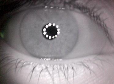
47 Table 4.5: Enrolled Captured Iris Images ID Number Iris Image


48 DATASETS In Table 4.5, the iris images that were captured and enrolled into the Iris Recognition System are displayed. These images undergone image processing as discussed in the previous chapter to have its iris template be produced. The iris templates were encoded using the Haar mother wavelet because according to Engr. Panganiban s work, it resulted with the best values of Hamming distance after every iris template were compared. The Inter-class comparisons of Haar wavelet at Level 4 vertical coefficient is shown on Table 4.6. As seen on the 40
49 table, the maximum HD value is and the minimum is A zero value indicates that the iris templates are perfectly matching each other. Table 4.6: Inter-class comparisons of Haar wavelet at Level 4 vertical coefficient Iris Id It is observable that when the Hamming distance value is greater than or equal to , the iris templates do not match. In table 4.6, the Intra-class comparisons of Haar Wavelet at level 4 vertical coefficient shows that when the HD value is less than , the iris template are from the same individual. Using the formula for the degrees of freedom: Where p is the mean which is equal to and the σ is the standard deviation which is equal to , the number of degrees of freedom is 80. According to statistics, this is the number of degrees of freedom that the values in this case, the HD values are free to vary. 41
50 Table 4.7: Intra-class comparisons of Haar wavelet at Level 4 vertical coefficient Iris Id IMPACT ANALYSIS The iris recognition system of Engr. Panganiban was taken to the next level by adding real time image processing features to it. This would be easier to use for the user would just look into the camera and wait for just a short period of time for the system to capture and process his or her iris. After the image was processed, it would immediately display if the person is authenticated or not. The designed iris recognition showed an increasing promise on the security system for it analyses the unchanging measurable biological characteristics that are unique to each individual. The design can be used as a prototype which can be implemented by in places demanding high security such as companies, governments, military, banks, airports, research laboratories and border control area. This would allow and limit access to a particular information or area. The government officials could also use this design for identifying and recording information of individuals and criminals. Physical methods of identification, which 42
51 includes anything requiring a password, personal identification number or key for building access or the like, are easily hacked or stolen but human iris cannot be stolen. This technology addresses the problems of both password management and fraud. 43
52 CHAPTER 5 CONCLUSION AND RECOMMENDATION CONCLUSION Based from the results obtained, the design was proven sufficient for iris recognition. The camera used is a manual focus- CMOS camera. In a Complementary Metal Oxide Semiconductor sensor, each pixel has its own charge-to-voltage conversion, and the sensor often includes amplifiers, noisecorrection, and digitalization circuits, so that the chip outputs digital bits. With these, the design complexity increases and the area available for light capture decreases. The correct positioning of the webcam, NIR LEDs and sensor produced a clearer and brighter iris image which really improves the performance of the iris recognition system. The NIR LEDs must be attached circular to the webcam so that noise that would be produced in the iris would be lessened. The light of the NIR LEDs would be directed to the pupil. Since the light reflection will be located in the pupil, it would not affect the iris segmentation and that the iris template. The case of the camera also lessens the noise since it blocks other factors that might affect the iris image and results. The proximity sensor has a delay of 5 seconds before it ss signal for the webcam to capture the iris image. There is a delay so that the user can position his or her eye properly to the device. 44
53 Also, the results showed that when the Hamming distance value is greater than or equal to , the iris templates do not match. The Intra-class comparison of Haar Wavelet at level 4 vertical coefficient shows that when the HD value is less than , the iris templates are from the same individual. From the results of the Hamming Distance in inter-class comparison, the Degrees of Freedom (DoF) computed is 80, which is higher than of Engr. Panganiban s work which is equal to 50. This shows that the comparison of iris templates in our design is more accurate. 45
54 RECOMMENDATION Although the obtained results proved that the design is sufficient for iris recognition, the following are still recommed for the improvement of the system s performance: 1. The proximity sensor may be replaced by an algorithm such as pattern recognition that will allow the software to capture the iris image once a circular shape is near the camera. 2. The digital camera can be converted to an Infrared Camera which would replace the webcam and NIR LEDs. 3. Artificial Intelligence, such as Fuzzy Logic, can be applied to the system to improve the performance of the Iris recognition system. 4. Embedding the Iris recognition system, its hardware and software into one device can be done to have the speed of the system indepent on the speed of the computer used and could also be portable. 46
55 REFERENCES Addison, P. (2002). The Illustrated Wavelet Transform Handbook, Institute of Physics. Bradley J., Brislawn, C., and Hopper, T. (1993). The FBI Wavelet/Scalar Quantization Standard for Gray-scale Fingerprint Image Compression. Tech. Report LA-UR , Los Alamos Nat'l Lab, Los Alamos, N.M. Boles, W.W. and Boashash, B.A. (1998). A human identification technique using images of the iris and wavelet transform, IEEE trans. on signal processing, vol. 46, issue 4. Canny, J. (1986). A Computational Approach To Edge Detection, IEEE Trans. Pattern Analysis and Machine Intelligence, 8: Cohn, J. (2006). Keeping an Eye on School Security: The Iris Recognition Project in New Jersey Schools. NIJ Journal, no Huifang, H. and Guangshu, H. (2005). Iris recognition based on adjustable scale wavelet transform. Proceedings of the 2005 IEEE. 47
56 Kong, W. and Zhang, D. (2001). Accurate iris segmentation based on novel reflection and eyelash detection model. Proceedings of 2001 International Symposium on Intelligent Multimedia, Video and Speech Processing, Hong Kong. Makram Nabti and Bouridane (2007). An effective iris recognition system based on wavelet maxima and Gabor filter bank. IEEE trans. on iris recognition. Masek, L. (2003). Recognition of Human Iris Patterns for Biometric Identification. Narote et al. (2007). An iris recognition based on dual tree complex wavelet transform. IEEE trans. on iris recognition. Panganiban, A. (2009). CCD Camera with Near-Infrared Illumination for Iris Recognition System. (2010). Implementation of Wavelet Algorithm for Iris Recognition System. 48
57 APPENDIX A Operation s Manual I. System Requirements CPU: Memory: Intel Core i GB Operating System: Windows 7 Software: MATLAB R2009a II. Installation Procedure 1. MATLAB R2009a installation (Recommed): 1.1 Load the MATLAB R2009a installer; it should automatically start the installation program whereby the first splash screen could be seen. 1.2 Agree to the Mathworks license, and then press Next. 1.3 Choose the Typical installation, and then press Next. 1.4 Choose the location of the installation, and then press Next. 1.5 If the location doesn t exist, you will be prompted to create it and MATLAB will ask you for the location on where the files will be installed. 1.6 Confirm the installation settings by pressing Install 1.7 MATLAB will now install, this may take several minutes 49
58 1.8 Close to the of the installation, you will be asked if you want to set up some file associations. Choose Yes to All. 1.9 After the installation has completed, you will be asked for the serial key for the software license. Enter the serial key and press Next MATLAB will initially make an internet connection to Mathworks. Answer Yes when asked if you are a student. Then press Next Enter the serial key and your address. Then press Next Continue with the rest of the registration process until the installation is complete. 2. Arduino Compiler installation: (For Windows) 2.1. Get an Arduino board, and connect it to your computer with a USB cable Download the Arduino environment on its official website. ( Install the drivers Wait for Windows to begin its driver installation process. After a few moments, the process will fail, despite its best efforts Click on the Start Menu, and open up the Control Panel. 50
59 While in the Control panel, navigate to System and Security. Next, click on System. Once the System window is up, open the Device Manager Look under Ports (COM & LPT). There should be an open port named Arduino UNO (COMxx) Right click on the Arduino UNO (COMxx) port and choose the Update Driver Software option Next, choose the Browse my computer for Driver software option Finally, navigate to and select the UNO s driver file, named ArduinoUNO.inf, located in the Drivers folder of the Arduino Software download (not the FTDI USB Drivers sub-directory) Windows will complete the driver installation from there. III. User s Manual How to use the Gizduino microcontroller and software: 1. Connect the Gizduino microcontroller to the USB port of the computer. 2. Open the Arduino Compiler. 3. From the Menu Bar, select Tools then choose Serial Port and select the designated port where the microcontroller is connected. 51
60 4. On the Arduino workspace, enter the arduino input/output server code that is listed on Appix C. 5. Compile the code by pressing Verify button to check for errors before uploading it to the microcontroller. 6. To upload the code to the microcontroller, press the Upload button. 7. Wait until the uploading is finished; A message Uploading Successful will be displayed. How to use the MATLAB iris recognition software: 1. Open a MATLAB workspace. 2. In the directory icon, browse the folder where the source code is located, in this case the programs are stored under a folder named Design Project. 3. In the command directory area, make sure that all files and folders are properly referenced. *Note: highlight all folders under the Design Project folder then right click. Choose add to path > all folders and sub folders. 4. In the current directory, right click on the irisrecognition.m program and choose Run File to run this program. 52
61 How to setup the Iris Recognition Design: *Note: The Iris Recognition software must be properly referenced on MATLAB and the arduino code provided must be uploaded on the arduino microcontroller. 1. Plug-in the source to 220-V supply and the USB cable to the Computer or Laptop. Be sure that the computer being used complies with the design s system requirements. 2. Make sure that the arduino input/output server code is uploaded to the microcontroller, and the Iris Recognition Software is on the current directory on MATLAB. 3. Open MATLAB R2009a, highlight all folders under Iris Recognition System folder (Software Design) then right click. Choose add to path > all folders and sub folders. Then run the Matlab program. 4. Run the MATLAB software irisrecognition.m provided. 5. Adjust the position of the Camera and IR LEDs to where the subject is comfortable with; just be sure that it would capture the subject s iris image accurately. Then compile and run the MATLAB program of iris recognition system. 6. The User must move his/her head close to the camera within the proximity range 4 to 5-cm away. From here the design must perform its auto-capture and real-time process of data. 53
62 7. If the iris image captured isn t within the authenticated list on the database, the user will be asked to whether or not enrol the iris image. Otherwise the program will simply display unauthenticated iris image pattern. 8. After the authentication the program will go back to its status of autocapturing an iris image. 9. To terminate, simply exit the MATLAB program. IV. Troubleshooting Guides and Procedures 1. If there is a problem on the Arduino Connection on MATLAB a) Upload the adiosrv.pde on the Gizduino b) Check if the COM PORT where the Gizduino is connected is the same on the SerialPort() definition on MATLAB 2. If the image is blurred, check and adjust the focus of the camera. Twist its lens to have the desired focus. 3. Uploading Errors on Gizduino a) Check the syntax for errors. b) Consult the website, for more information. 4. Unknown MATLAB function a) Check if the program files are located at the current directory window of MATLAB. 54
63 b) If the files are already the current directory of MATLAB, select all files and right click then add to path all the folders and subfolders. 5. If there are many cameras connected and installed on the laptop, check the image acquisition toolbox of MATLAB and select the adaptor name and device ID of the desired camera to be used. 6. There is no light emitted by the LEDs a) Make sure that the polarity on the source to LED connection is correct. b) Check the proper connection of the LEDs in series and parallel. c) Plug the power supply. V. Error Definitions MATLAB: 1. Error in using videoinput in MATLAB The camera device is not detected by MATLAB or its DEVICEID or adapter name is invalid. 2. Error at segmentiris.m There are no detectable circular patterns. 3. COM PORT unavailable- There is no devices connected on the particular Serial COM port 4. Function or CD diagnostics or directory not found- make sure that the current directory in MATLAB is the one where the.m files are placed 55
64 Arduino Compiler: 1. Error Compiling- Check the syntax for errors 2. Serial Port not found- The Gizduino microcontroller is connected to a different Serial Port or there is nothing connected. 56

65 APPENDIX B Pictures of Prototype 57
66 APPENDIX C Program Listing Arduino.m classdef arduino < handle % This class defines an "arduino" object % Giampiero Campa, Aug 2010, Copyright 2009 The MathWorks, Inc. properties (SetAccess=private,GetAccess=private) aser % Serial Connection methods % constructor, connects to the board and creates an arduino object function a=arduino(comport) % Add target directories and save the updated path addpath(fullfile(pwd)); savepath % check nargin if nargin<1, comport='demo'; disp('note: a DEMO connection will be created'); disp('use a the com port, e.g. ''COM5'' as input argument to connect to the real board'); % check port if ~ischar(comport), error('the input argument must be a string, e.g. ''COM8'' '); % check if we are already connected if isa(a.aser,'serial') && isvalid(a.aser) && strcmpi(get(a.aser,'status'),'open'), disp(['it looks like Arduino is already connected to port ' comport ]); disp('delete the object to force disconnection'); disp('before attempting a connection to a different port.'); 58
67 return; % check whether serial port is currently used by MATLAB if ~isempty(instrfind({'port'},{comport})), disp(['the port ' comport ' is already used by MATLAB']); disp(['if you are sure that Arduino is connected to ' comport]); disp('then delete the object to disconnect and execute:'); disp([' delete(instrfind({''port''},{''' comport '''}))']); disp('to delete the port before attempting another connection'); error(['port ' comport ' already used by MATLAB']); % define serial object a.aser=serial(comport); % connection if strcmpi(get(a.aser,'port'),'demo'), % handle demo mode fprintf(1,'demo mode connection..'); for i=1:4, fprintf(1,'.'); pause(1); fprintf(1,'\n'); pause(1); % chk is 1 or 2 deping on the script running on the board chk=round(1+rand); else % actual connection % open port try fopen(a.aser); catch ME, disp(me.message) delete(a); error(['could not open port: ' comport]); % it takes several seconds before any operation could be attempted 59
68 fprintf(1,'attempting connection..'); for i=1:4, fprintf(1,'.'); pause(1); fprintf(1,'\n'); % query script type fwrite(a.aser,[57 57],'uchar'); chk=fscanf(a.aser,'%d'); % exit if there was no answer if isempty(chk) delete(a); error('connection unsuccessful, please make sure that the Arduino is powered on, running either adiosrv.pde or mororsrv.pde, and that the board is connected to the indicated serial port. You might also try to unplug and re-plug the USB cable before attempting a reconnection.'); % check returned value if chk==1, disp('basic I/O Script detected!'); elseif chk==2, disp('motor Shield Script detected!'); else delete(a); error('unknown Script. Please make sure that either adiosrv.pde or motorsrv.pde are running on the Arduino'); % sets a.mots flag a.mots=chk-1; % set a.aser tag a.aser.tag='ok'; % initialize pin vector (-1 is unassigned, 0 is input, 1 is output) a.pins=-1*ones(1,19); % initialize servo vector (-1 is unknown, 0 is detached, 1 is attached) 60
69 a.srvs=0*ones(1,2); % initialize motor vector (0 to 255 is the speed) a.mspd=0*ones(1,4); % initialize stepper vector (0 to 255 is the speed) a.sspd=0*ones(1,2); % notify successful installation disp('arduino successfully connected!'); % arduino % distructor, deletes the object function delete(a) % if it is a serial, valid and open then close it if isa(a.aser,'serial') && isvalid(a.aser) && strcmpi(get(a.aser,'status'),'open'), if ~isempty(a.aser.tag), try % trying to leave it in a known unharmful state for i=2:19, a.pinmode(i,'output'); a.digitalwrite(i,0); a.pinmode(i,'input'); catch ME % disp but proceed anyway disp(me.message); disp('proceeding to deletion anyway'); fclose(a.aser); % if it's an object delete it if isobject(a.aser), delete(a.aser); % delete 61
70 % disp, displays the object function disp(a) % display if isvalid(a), if isa(a.aser,'serial') && isvalid(a.aser), disp(['<a href="matlab:help arduino">arduino</a> object connected to ' a.aser.port ' port']); if a.mots==1, disp('motor Shield Server running on the arduino board'); disp(' '); a.servostatus a.motorspeed a.stepperspeed disp(' '); disp('servo Methods: <a href="matlab:help servostatus">servostatus</a> <a href="matlab:help servoattach">servoattach</a> <a href="matlab:help servodetach">servodetach</a> <a href="matlab:help servoread">servoread</a> <a href="matlab:help servowrite">servowrite</a>'); disp('dc Motors and Stepper Methods: <a href="matlab:help motorspeed">motorspeed</a> <a href="matlab:help motorrun">motorrun</a> <a href="matlab:help stepperspeed">stepperspeed</a> <a href="matlab:help stepperstep">stepperstep</a>'); else disp('io Server running on the arduino board'); disp(' '); a.pinmode disp(' '); disp('pin IO Methods: <a href="matlab:help pinmode">pinmode</a> <a href="matlab:help digitalread">digitalread</a> <a href="matlab:help digitalwrite">digitalwrite</a> <a href="matlab:help analogread">analogread</a> <a href="matlab:help analogwrite">analogwrite</a>'); disp(' '); else disp('<a href="matlab:help arduino">arduino</a> object connected to an invalid serial port'); disp('please delete the arduino object'); disp(' '); else 62
71 disp('invalid <a href="matlab:help arduino">arduino</a> object'); disp('please clear the object and instantiate another one'); disp(' '); % pin mode, changes pin mode function pinmode(a,pin,str) % a.pinmode(pin,str); specifies the pin mode of a digital pins. % The first argument before the function name, a, is the arduino object. % The first argument, pin, is the number of the digital pin (2 to 19). % The second argument, str, is a string that can be 'input' or 'output', % Called with one argument, as a.pin(pin) it returns the mode of % the digital pin, called without arguments, prints the mode of all the % digital pins. Note that the digital pins from 0 to 13 are located on % the upper right part of the board, while the digital pins from 14 to 19 % are better known as "analog input" pins and are located in the lower % right corner of the board. % % Examples: % a.pinmode(11,'output') % sets digital pin #11 as output % a.pinmode(10,'input') % sets digital pin #10 as input % val=a.pinmode(10); % returns the status of digital pin #10 % a.pinmode(5); % prints the status of digital pin #5 % a.pinmode; % prints the status of all pins % %%%%%%%%%%%%%%%%%%%%%%%%% ARGUMENT CHECKING %%%%%%%%%%%%%%%%%%%%%%%%%%%%%%% % check nargin if nargin>3, error('this function cannot have more than 3 arguments, object, pin and str'); % first argument must be the arduino variable if ~isa(a,'arduino'), error('the first argument must be an arduino variable'); % if pin argument is there check it if nargin>1, 63
72 errstr=arduino.checknum(pin,'pin number',2:19); if ~isempty(errstr), error(errstr); % if str argument is there check it if nargin>2, errstr=arduino.checkstr(str,'pin mode',{'input','output'}); if ~isempty(errstr), error(errstr); % perform the requested action if nargin==3, % check a.aser for validity errstr=arduino.checkser(a.aser,'valid'); if ~isempty(errstr), error(errstr); %%%%%%%%%%%%%%%%%%%%%%%%% CHANGE PIN MODE %%%%%%%%%%%%%%%%%%%%%%%%%%%%%%%%% % assign value if lower(str(1))=='o', val=1; else val=0; if strcmpi(get(a.aser,'port'),'demo'), % handle demo mode here % average digital output delay pause(0.0087); else % do the actual action here % check a.aser for openness errstr=arduino.checkser(a.aser,'open'); if ~isempty(errstr), error(errstr); % s mode, pin and value fwrite(a.aser,[48 97+pin 48+val],'uchar'); % detach servo 1 or 2 if pins 10 or 9 are used if pin==10 pin==9, a.servodetach(11-pin); 64
73 % store 0 for input and 1 for output a.pins(pin)=val; elseif nargin==2, % print pin mode for the requested pin mode={'unassigned','set as INPUT','set as OUTPUT'}; disp(['digital Pin ' num2str(pin) ' is currently ' mode{2+a.pins(pin)}]); else % print pin mode for each pin mode={'unassigned','set as INPUT','set as OUTPUT'}; for i=2:19; disp(['digital Pin ' num2str(i,'%02d') ' is currently ' mode{2+a.pins(i)}]); % pinmode % digital read function val=digitalread(a,pin) pins the % val=a.digitalread(pin); performs digital input on a given arduino pin. % The first argument before the function name, a, is the arduino object. % The argument pin, is the number of the digital pin (2 to 19) % where the digital input needs to be performed. Note that the digital % from 0 to 13 are located on the upper right part of the board, while % digital pins from 14 to 19 are better known as "analog input" pins and % are located in the lower right corner of the board. % % Example: % val=a.digitalread(4); % reads pin #4 % %%%%%%%%%%%%%%%%%%%%%%%%% ARGUMENT CHECKING %%%%%%%%%%%%%%%%%%%%%%%%%%%%%%% 65
74 % check nargin if nargin~=2, error('function must have the "pin" argument'); % first argument must be the arduino variable if ~isa(a,'arduino'), error('the first argument must be an arduino variable'); % check pin errstr=arduino.checknum(pin,'pin number',2:19); if ~isempty(errstr), error(errstr); % check a.aser for validity errstr=arduino.checkser(a.aser,'valid'); if ~isempty(errstr), error(errstr); %%%%%%%%%%%%%%%%%%%%%%%%% PERFORM DIGITAL INPUT %%%%%%%%%%%%%%%%%%%%%%%%%%% if strcmpi(get(a.aser,'port'),'demo'), % handle demo mode else % average digital input delay pause(0.0247); % output 0 or 1 randomly val=round(rand); % check a.aser for openness errstr=arduino.checkser(a.aser,'open'); if ~isempty(errstr), error(errstr); % s mode and pin fwrite(a.aser,[49 97+pin],'uchar'); % get value val=fscanf(a.aser,'%d'); 66
75 % digitalread % digital write function digitalwrite(a,pin,val) part board. % a.digitalwrite(pin,val); performs digital output on a given pin. % The first argument before the function name, a, is the arduino object. % The second argument, pin, is the number of the digital pin (2 to 19) % where the digital output needs to be performed. % The third argument, val, is the value (either 0 or 1) for the output % Note that the digital pins from 0 to 13 are located on the upper right % of the board, while the digital pins from 14 to 19 are better known as % "analog input" pins and are located in the lower right corner of the % % Examples: % a.digitalwrite(13,1); % sets pin #13 high % a.digitalwrite(13,0); % sets pin #13 low % %%%%%%%%%%%%%%%%%%%%%%%%% ARGUMENT CHECKING %%%%%%%%%%%%%%%%%%%%%%%%%%%%%%% % check nargin if nargin~=3, error('function must have the "pin" and "val" arguments'); % first argument must be the arduino variable if ~isa(a,'arduino'), error('the first argument must be an arduino variable'); % check pin errstr=arduino.checknum(pin,'pin number',2:19); if ~isempty(errstr), error(errstr); % check val errstr=arduino.checknum(val,'value',0:1); if ~isempty(errstr), error(errstr); % pin should be configured as output if a.pins(pin)~=1, 67
76 warning('matlab:arduino:digitalwrite',['if digital pin ' num2str(pin) ' is set as input, digital output takes place only after using a.pinmode(' num2str(pin) ',''output''); ']); % check a.aser for validity errstr=arduino.checkser(a.aser,'valid'); if ~isempty(errstr), error(errstr); %%%%%%%%%%%%%%%%%%%%%%%%% PERFORM DIGITAL OUTPUT %%%%%%%%%%%%%%%%%%%%%%%%%% if strcmpi(get(a.aser,'port'),'demo'), % handle demo mode else % average digital output delay pause(0.0087); % check a.aser for openness errstr=arduino.checkser(a.aser,'open'); if ~isempty(errstr), error(errstr); % s mode, pin and value fwrite(a.aser,[50 97+pin 48+val],'uchar'); % digitalwrite % analog read function val=analogread(a,pin) pin. to 5) val, volts, % val=a.analogread(pin); Performs analog input on a given arduino % The first argument before the function name, a, is the arduino object. % The second argument, pin, is the number of the analog input pin (0 % where the analog input needs to be performed. The returned value, % ranges from 0 to 1023, with 0 corresponding to an input voltage of 0 68
77 analog does % and 1023 to a value of 5 volts. Therefore the resolution is.0049 volts % (4.9 mv) per unit. % Note that the analog input pins 0 to 5 are also known as digital pins % from 14 to 19, and are located on the lower right corner of the board. % Specifically, analog input pin 0 corresponds to digital pin 14, and % input pin 5 corresponds to digital pin 19. Performing analog input % not affect the digital state (high, low, digital input) of the pin. % % Example: % val=a.analogread(0); % reads analog input pin # 0 % %%%%%%%%%%%%%%%%%%%%%%%%% ARGUMENT CHECKING %%%%%%%%%%%%%%%%%%%%%%%%%%%%%%% % check nargin if nargin~=2, error('function must have the "pin" argument'); % first argument must be the arduino variable if ~isa(a,'arduino'), error('the first argument must be an arduino variable'); % check pin errstr=arduino.checknum(pin,'analog input pin number',0:5); if ~isempty(errstr), error(errstr); % check a.aser for validity errstr=arduino.checkser(a.aser,'valid'); if ~isempty(errstr), error(errstr); %%%%%%%%%%%%%%%%%%%%%%%%% PERFORM ANALOG INPUT %%%%%%%%%%%%%%%%%%%%%%%%%%%% if strcmpi(get(a.aser,'port'),'demo'), % handle demo mode % average analog input delay pause(0.0267); 69
78 else % output a random value between 0 and 1023 val=round(1023*rand); % check a.aser for openness errstr=arduino.checkser(a.aser,'open'); if ~isempty(errstr), error(errstr); % s mode and pin fwrite(a.aser,[51 97+pin],'uchar'); % get value val=fscanf(a.aser,'%d'); % analogread % function analog write function analogwrite(a,pin,val) % a.analogwrite(pin,val); Performs analog output on a given arduino pin. % The first argument before the function name, a, is the arduino object. % The first argument, pin, is the number of the DIGITAL pin where the analog % (PWM) output needs to be performed. Allowed pins for AO are 3,5,6,9,10,11 % The second argument, val, is the value from 0 to 255 for the level of % analog output. Note that the digital pins from 0 to 13 are located on the % upper right part of the board. % % Examples: % a.analogwrite(11,90); % sets pin #11 to 90/255 % a.analogwrite(3,10); % sets pin #3 to 10/255 % %%%%%%%%%%%%%%%%%%%%%%%%% ARGUMENT CHECKING %%%%%%%%%%%%%%%%%%%%%%%%%%%%%%% % check nargin if nargin~=3, 70
79 error('function must have the "pin" and "val" arguments'); % first argument must be the arduino variable if ~isa(a,'arduino'), error('the first argument must be an arduino variable'); % check pin errstr=arduino.checknum(pin,'pwm pin number',[ ]); if ~isempty(errstr), error(errstr); % check val errstr=arduino.checknum(val,'analog output level',0:255); if ~isempty(errstr), error(errstr); % pin should be configured as output if a.pins(pin)~=1, warning('matlab:arduino:analogwrite',['if digital pin ' num2str(pin) ' is set as input, pwm output takes place only after using a.pinmode(' num2str(pin) ',''output''); ']); % check a.aser for validity errstr=arduino.checkser(a.aser,'valid'); if ~isempty(errstr), error(errstr); %%%%%%%%%%%%%%%%%%%%%%%%% PERFORM ANALOG OUTPUT %%%%%%%%%%%%%%%%%%%%%%%%%%% if strcmpi(get(a.aser,'port'),'demo'), % handle demo mode else % average analog output delay pause(0.0088); % check a.aser for openness errstr=arduino.checkser(a.aser,'open'); if ~isempty(errstr), error(errstr); % s mode, pin and value fwrite(a.aser,[52 97+pin val],'uchar'); 71
80 % analogwrite % methods methods (Static) % static methods function errstr=checknum(num,description,allowed) % errstr=arduino.checknum(num,description,allowed); Checks numeric argument. % This function checks the first argument, num, described in the string % given as a second argument, to make sure that it is real, scalar, % and that it is equal to one of the entries of the vector of allowed % values given as a third argument. If the check is successful then the % returned argument is empty, otherwise it is a string specifying % the type of error. % preliminary: check nargin if nargin~=3, error('checknum needs 3 arguments, please read the help'); % preliminary: check description if isempty(description) ~ischar(description) error('checknum second argument must be a string'); % preliminary: check allowed if isempty(allowed) ~isnumeric(allowed) error('checknum third argument must be a numeric vector'); % initialize error string errstr=[]; % check num for type if ~isnumeric(num), errstr=['the ' description ' must be numeric']; return 72
81 % check num for size if numel(num)~=1, errstr=['the ' description ' must be a scalar']; return % check num for realness if ~isreal(num), errstr=['the ' description ' must be a real value']; return % check num against allowed values if ~any(allowed==num), % form right error string if numel(allowed)==1, errstr=['unallowed value for ' description ', the value must be exactly ' num2str(allowed(1))]; elseif numel(allowed)==2, errstr=['unallowed value for ' description ', the value must be either ' num2str(allowed(1)) ' or ' num2str(allowed(2))]; elseif max(diff(allowed))==1, errstr=['unallowed value for ' description ', the value must be an integer going from ' num2str(allowed(1)) ' to ' num2str(allowed())]; else errstr=['unallowed value for ' description ', the value must be one of the following: ' mat2str(allowed)]; % checknum function errstr=checkstr(str,description,allowed) % errstr=arduino.checkstr(str,description,allowed); Checks string argument. % This function checks the first argument, str, described in the string % given as a second argument, to make sure that it is a string, and that % its first character is equal to one of the entries in the cell of 73
82 % allowed characters given as a third argument. If the check is successful % then the returned argument is empty, otherwise it is a string specifying % the type of error. % preliminary: check nargin if nargin~=3, error('checkstr needs 3 arguments, please read the help'); % preliminary: check description if isempty(description) ~ischar(description) error('checknum second argument must be a string'); % preliminary: check allowed if ~iscell(allowed) numel(allowed)<2, error('checknum third argument must be a cell with at least 2 entries'); % initialize error string errstr=[]; % check string for type if ~ischar(str), errstr=['the ' description ' argument must be a string']; return % check string for size if numel(str)<1, errstr=['the ' description ' argument cannot be empty']; return % check str against allowed values if ~any(strcmpi(str,allowed)), % make sure this is a hozizontal vector allowed=allowed(:)'; % add a comma at the of each value 74
83 for i=1:length(allowed)-1, allowed{i}=['''' allowed{i} ''', ']; % form error string errstr=['unallowed value for ' description ', the value must be either: ' allowed{1:-1} 'or ''' allowed{} '''']; return % checkstr function errstr=checkser(ser,chk) % errstr=arduino.checkser(ser,chk); Checks serial connection argument. % This function checks the first argument, ser, to make sure that either: % 1) it is a valid serial connection (if the second argument is 'valid') % 3) it is open (if the second argument is 'open') % If the check is successful then the returned argument is empty, % otherwise it is a string specifying the type of error. % preliminary: check nargin if nargin~=2, error('checkser needs two arguments, please read the help'); % initialize error string errstr=[]; % check serial connection switch lower(chk), case 'valid', % make sure is a serial port if ~isa(ser,'serial'), disp('arduino is not connected, please re-create the object before using this function.'); errstr='arduino not connected'; return % make sure is valid if ~isvalid(ser), 75
84 disp('serial connection invalid, please recreate the object to reconnect to a serial port.'); errstr='serial connection invalid'; return case 'open', % check openness if ~strcmpi(get(ser,'status'),'open'), disp('serial connection not opened, please recreate the object to reconnect to a serial port.'); errstr='serial connection not opened'; return otherwise % chackser % complain error('second argument must be either ''valid'' or ''open'''); % static methods % class def irisrecognition.m function varargout = irisrecognition(varargin) % Begin initialization code - DO NOT EDIT gui_singleton = 1; gui_state = struct('gui_name', mfilename,... 'gui_singleton', gui_singleton,... 'gui_layoutfcn', [],... 'gui_callback', []); if nargin && ischar(varargin{1}) 76
85 gui_state.gui_callback = str2func(varargin{1}); if nargout [varargout{1:nargout}] = gui_mainfcn(gui_state, varargin{:}); else gui_mainfcn(gui_state, varargin{:}); % End initialization code - DO NOT EDIT % --- Executes just before untitled is made visible. function irisrecognition_openingfcn(hobject, eventdata, handles, varargin) %setup webcam %vidobj = videoinput('winvideo',1,'yuy2_640x480'); %set(handles.statuslbl,'string','connecting to camera'); vidobj = videoinput('winvideo',3,'rgb24_640x480'); axes(handles.cameraaxes); videores = get(vidobj, 'VideoResolution'); numberofbands = get(vidobj, 'NumberOfBands'); fprintf(1, 'Video resolution = %d wide by %d tall, by %d color',... videores(1), videores(2), numberofbands); handletoimage = image( zeros([videores(2), videores(1),... numberofbands], 'uint8') ); set(vidobj,'returnedcolorspace','rgb'); uint8('img'); %set(handles.statuslbl,'string','camera ready!'); preview(vidobj, handletoimage); % setup webcam %set arduino %set(handles.statuslbl,'string','connecting to Gizduino'); gizduinoport = arduino('com4'); %set(handles.statuslbl,'string','gizduino ready!'); gizduinoport.pinmode(8, 'input');%where the output of the proximity sensor goes gizduinoport.pinmode(11, 'output');% made a +5V supply on pin 11 for the +V of the proximity sensor gizduinoport.digitalwrite(11, 1);%output high signal on pin 11 (5V) % set arduino while gizduinoport ~= 0 %habang nakaconnect ang microcontroller mywait(5);%wait for (n) seconds if gizduinoport.digitalread(8) == 0 %kapag may harang % set(handles.statuslbl,'string','capturing iris image...'); 77
86 frame = getsnapshot(vidobj); %capture imwrite(frame,'f:\tempimage.bmp'); %save % set(handles.statuslbl,'string','saving...'); imwrite(frame,'f:\pictures\tempimage.bmp'); imwrite(frame,'f:\pictures\tempimage1.bmp'); %match % set(handles.statuslbl,'string','searching for matches...'); output = irisrecognitionprocess('f:\tempimage.bmp'); % set(handles.statuslbl,'string','searching Completed!'); % frmaddname conn = database('thesis','sa','mssql'); cursor = exec(conn,'select IrisId,IrisTemplate from IrisDataBankDesign'); cursor = fetch(cursor); intmax = size(cursor.data,1); mat1 = output; output = mat2str(mat1); mat1 = str2mat(output); irisfound = 0; threshold = ; int = 0; for int = 1:intmax mat2 = str2mat(cursor.data(int,2)); HD = gethammingdistance(mat1,mat2); HD_values(int) = HD; statuslbl = HD; if HD > 0 & HD < threshold irisfound = 1; set(handles.hdlistbox,'string',hd_values); close(cursor); close(conn); if irisfound == 1 msgbox('authenticated!','iris RECOGNITION') else msgbox('iris Not Authenticated!','IRIS RECOGNITION') mywait(2); set(handles.enrollbtn,'enable','on'); % match else % set(handles.statuslbl,'string','idle'); 78
87 % Choose default command line output for untitled handles.output = hobject; % Update handles structure guidata(hobject, handles); % UIWAIT makes untitled wait for user response (see UIRESUME) % uiwait(handles.figure1); % --- Outputs from this function are returned to the command line. function varargout = irisrecognition_outputfcn(hobject, eventdata, handles) % Get default command line output from handles structure varargout{1} = handles.output; % --- Executes on button press in exitbtn. function exitbtn_callback(hobject, eventdata, handles) close(handles.figure1) % --- Executes on selection change in HdListbox. function HdListbox_Callback(hObject, eventdata, handles) Hints: contents = get(hobject,'string') returns HdListbox contents as cell array % contents{get(hobject,'value')} returns selected item from HdListbox % --- Executes during object creation, after setting all properties. function HdListbox_CreateFcn(hObject, eventdata, handles) if ispc && isequal(get(hobject,'backgroundcolor'), get(0,'defaultuicontrolbackgroundcolor')) set(hobject,'backgroundcolor','white'); % --- Executes on button press in EnrollBtn. function EnrollBtn_Callback(hObject, eventdata, handles) frmaddname 79
88 irisrecognitionprocess.m function [output] = irisrecognitionprocess(eyeimage_filename) % path for writing diagnostic images global DIAGPATH DIAGPATH = 'diagnostics\'; %normalisation parameters radial_res = 24; angular_res = 240; %feature encoding parameters nscales=1; minwavelength=18; mult=1; % not applicable if using nscales = 1 sigmaonf=0.5; eyeimage = imread(eyeimage_filename); eyeimage1 = imresize(eyeimage,[225,300]);%convert to grayscale 8bit eyeimage = rgb2gray(eyeimage1); savefile = [eyeimage_filename]; [stat,mess]=fileattrib(savefile); [circleiris circlepupil imagewithnoise] = segmentiris(eyeimage); save(savefile,'circleiris','circlepupil','imagewithnoise'); % WRITE NOISE IMAGE imagewithnoise2 = uint8(imagewithnoise); imagewithcircles = uint8(eyeimage); %get pixel coords for circle around iris [x,y] = circlecoords([circleiris(2),circleiris(1)],circleiris(3),size(eyeimage)); ind2 = sub2ind(size(eyeimage),double(y),double(x)); %get pixel coords for circle around pupil [xp,yp] = circlecoords([circlepupil(2),circlepupil(1)],circlepupil(3),size(eyeimage)); ind1 = sub2ind(size(eyeimage),double(yp),double(xp)); 80
89 % Write noise regions imagewithnoise2(ind2) = 255; imagewithnoise2(ind1) = 255; % Write circles overlayed imagewithcircles(ind2) = 255; imagewithcircles(ind1) = 255; w = cd; cd(diagpath); imwrite(imagewithcircles,[eyeimage_filename,'-segmented.jpg'],'jpg'); cd(w); % perform normalisation [polar_array noise_array] = normaliseiris(imagewithnoise, circleiris(2),... circleiris(1), circleiris(3), circlepupil(2), circlepupil(1), circlepupil(3),eyeimage_filename, radial_res, angular_res); % WRITE NORMALISED PATTERN, AND NOISE PATTERN w = cd; cd(diagpath); imwrite(polar_array,[eyeimage_filename,'-polar.jpg'],'jpg'); cd(w); %ENCODE THE TEMPLATE USING WAVELET %[output] = encode(polar_array, noise_array, nscales, minwavelength, mult, %sigmaonf); [output] = encode(polar_array); mywait.m % Waits for the specified number of seconds function mywait(deltat) if(deltat>0) % condition t=timer('timerfcn','mywait(0)','startdelay',deltat); start(t); wait(t); 81
90 frmaddname.m function varargout = frmaddname(varargin) % Begin initialization code - DO NOT EDIT gui_singleton = 1; gui_state = struct('gui_name', mfilename,... 'gui_singleton', gui_singleton,... 'gui_layoutfcn', [],... 'gui_callback', []); if nargin && ischar(varargin{1}) gui_state.gui_callback = str2func(varargin{1}); if nargout [varargout{1:nargout}] = gui_mainfcn(gui_state, varargin{:}); else gui_mainfcn(gui_state, varargin{:}); % End initialization code - DO NOT EDIT % --- Executes just before frmaddname is made visible. function frmaddname_openingfcn(hobject, eventdata, handles, varargin) % Choose default command line output for frmaddname handles.output = hobject; % Update handles structure guidata(hobject, handles); %pixels set( handles.frmaddname,... 'Units', 'pixels' ); %get your display size screensize = get(0, 'ScreenSize'); %calculate the center of the display position = get( handles.frmaddname,... 'Position' ); position(1) = (screensize(3)-position(3))/2; 82
91 position(2) = (screensize(4)-position(4))/2; %center the window set( handles.frmaddname,... 'Position', position ); % --- Outputs from this function are returned to the command line. function varargout = frmaddname_outputfcn(hobject, eventdata, handles) % Get default command line output from handles structure varargout{1} = handles.output; function txtname_callback(hobject, eventdata, handles) % --- Executes during object creation, after setting all properties. function txtname_createfcn(hobject, eventdata, handles) if ispc set(hobject,'backgroundcolor','white'); else set(hobject,'backgroundcolor',get(0,'defaultuicontrolbackgroundcolor')); % --- Executes on button press in btnok. function btnok_callback(hobject, eventdata, handles) frame = imread('f:\pictures\tempimage.bmp'); HH = findobj(gcf,'tag','txtname'); ID = get(hh,'string'); IDcat = strcat('f:\pictures\',id); filename = strcat(idcat,'.jpg'); if exist(filename,'file') errordlg('name already exist.','information'); return else imwrite(frame,filename,'jpg'); output = irisrecognitionprocess(filename); conn = database('thesis','sa','mssql'); colnames = {'IrisPath','IrisTemplate'}; output = mat2str(output); exdata = {filename,output}; 83
92 insert(conn,'iris.dbo.irisdatabankdesign', colnames, exdata) close(conn); close; % --- Executes on button press in btncancel. function btncancel_callback(hobject, eventdata, handles) close; segmentiris.m % segmentiris - peforms automatic segmentation of the iris region % from an eye image. Also isolates noise areas such as occluding % eyelids and eyelashes. % % Usage: % [circleiris, circlepupil, imagewithnoise] = segmentiris(image) % % Arguments: % eyeimage - the input eye image % % Output: % circleiris - centre coordinates and radius % of the detected iris boundary % circlepupil - centre coordinates and radius % of the detected pupil boundary % imagewithnoise - original eye image, but with % location of noise marked with % NaN values function [circleiris, circlepupil, imagewithnoise] = segmentiris(eyeimage) lpupilradius = 20; upupilradius = 75; lirisradius = 80; uirisradius = 95; % define scaling factor to speed up Hough transform scaling = 0.4; reflecthres = 240; % find the iris boundary 84
93 [row, col, r] = findcircle(eyeimage, lirisradius, uirisradius, scaling, 2, 0.20, 0.19, 1.00, 0.00); circleiris = [row col r]; rowd = double(row); cold = double(col); rd = double(r); irl = round(rowd-rd); iru = round(rowd+rd); icl = round(cold-rd); icu = round(cold+rd); imgsize = size(eyeimage); if irl < 1 irl = 1; if icl < 1 icl = 1; if iru > imgsize(1) iru = imgsize(1); if icu > imgsize(2) icu = imgsize(2); % to find the inner pupil, use just the region within the previously % detected iris boundary imagepupil = eyeimage( irl:iru,icl:icu); %find pupil boundary [rowp, colp, r] = findcircle(imagepupil, lpupilradius, upupilradius,0.6,2,0.25,0.25,1.00,1.00); rowp = double(rowp); colp = double(colp); r = double(r); 85
94 row = double(irl) + rowp; col = double(icl) + colp; row = round(row); col = round(col); circlepupil = [row col r]; % set up array for recording noise regions % noise pixels will have NaN values imagewithnoise = double(eyeimage); %find top eyelid topeyelid = imagepupil(1:(rowp-r),:); lines = findline(topeyelid); if size(lines,1) > 0 [xl yl] = linecoords(lines, size(topeyelid)); yl = double(yl) + irl-1; xl = double(xl) + icl-1; yla = max(yl); y2 = 1:yla; ind3 = sub2ind(size(eyeimage),yl,xl); imagewithnoise(ind3) = NaN; imagewithnoise(y2, xl) = NaN; %find bottom eyelid bottomeyelid = imagepupil((rowp+r):size(imagepupil,1),:); lines = findline(bottomeyelid); if size(lines,1) > 0 [xl yl] = linecoords(lines, size(bottomeyelid)); yl = double(yl)+ irl+rowp+r-2; xl = double(xl) + icl-1; yla = min(yl); y2 = yla:size(eyeimage,1); 86
95 ind4 = sub2ind(size(eyeimage),yl,xl); imagewithnoise(ind4) = NaN; imagewithnoise(y2, xl) = NaN; ref = eyeimage < 100; coords = find(ref==1); imagewithnoise(coords) = NaN; nonmaxsup.m % NONMAXSUP % % Usage: % im = nonmaxsup(inimage, orient, radius); % % Function for performing non-maxima suppression on an image using an % orientation image. It is assumed that the orientation image gives % feature normal orientation angles in degrees (0-180). % % input: % inimage - image to be non-maxima suppressed. % % orient - image containing feature normal orientation angles in degrees % (0-180), angles positive anti-clockwise. % % radius - distance in pixel units to be looked at on each side of each % pixel when determining whether it is a local maxima or not. % (Suggested value about ) % % Note: This function is slow (1-2 mins to process a 256x256 image). It uses % bilinear interpolation to estimate intensity values at ideal, real-valued pixel % locations on each side of pixels to determine if they are local maxima. function im = nonmaxsup(inimage, orient, radius) if size(inimage) ~= size(orient) error('image and orientation image are of different sizes'); 87
96 if radius < 1 error('radius must be >= 1'); [rows,cols] = size(inimage); im = zeros(rows,cols); % Preallocate memory for output image for speed iradius = ceil(radius); % Precalculate x and y offsets relative to centre pixel for each orientation angle angle = [0:180].*pi/180; % Array of angles in 1 degree increments (but in radians). xoff = radius*cos(angle); % x and y offset of points at specified radius and angle yoff = radius*sin(angle); % from each reference position. hfrac = xoff - floor(xoff); % Fractional offset of xoff relative to integer location vfrac = yoff - floor(yoff); % Fractional offset of yoff relative to integer location orient = fix(orient)+1; % Orientations start at 0 degrees but arrays start % with index 1. % Now run through the image interpolating grey values on each side % of the centre pixel to be used for the non-maximal suppression. for row = (iradius+1):(rows - iradius) for col = (iradius+1):(cols - iradius) or = orient(row,col); % Index into precomputed arrays x = col + xoff(or); y = row - yoff(or); % x, y location on one side of the point in question fx = floor(x); % Get integer pixel locations that surround location x,y cx = ceil(x); fy = floor(y); cy = ceil(y); tl = inimage(fy,fx); % Value at top left integer pixel location. tr = inimage(fy,cx); % top right bl = inimage(cy,fx); % bottom left br = inimage(cy,cx); % bottom right upperavg = tl + hfrac(or) * (tr - tl); % Now use bilinear interpolation to loweravg = bl + hfrac(or) * (br - bl); % estimate value at x,y 88
97 v1 = upperavg + vfrac(or) * (loweravg - upperavg); if inimage(row, col) > v1 % We need to check the value on the other side... x = col - xoff(or); question y = row + yoff(or); % x, y location on the `other side' of the point in fx = floor(x); cx = ceil(x); fy = floor(y); cy = ceil(y); tl = inimage(fy,fx); tr = inimage(fy,cx); bl = inimage(cy,fx); % Value at top left integer pixel location. % top right % bottom left % bottom right br = inimage(cy,cx); upperavg = tl + hfrac(or) * (tr - tl); loweravg = bl + hfrac(or) * (br - bl); v2 = upperavg + vfrac(or) * (loweravg - upperavg); if inimage(row,col) > v2 % This is a local maximum. im(row, col) = inimage(row, col); % Record value in the output image. linecoords.m % linecoords - returns the x y coordinates of positions along a line % % Usage: % [x,y] = linecoords(lines, imsize) % % Arguments: % lines - an array containing parameters of the line in % form % imsize - size of the image, needed so that x y coordinates % are within the image boundary % % Output: % x - x coordinates 89
98 % y - corresponding y coordinates % function [x,y] = linecoords(lines, imsize) xd = [1:imsize(2)]; yd = (-lines(3) - lines(1)*xd ) / lines(2); coords = find(yd>imsize(1)); yd(coords) = imsize(1); coords = find(yd<1); yd(coords) = 1; x = int32(xd); y = int32(yd); hysthresh.m % HYSTHRESH - Hysteresis thresholding % % Usage: bw = hysthresh(im, T1, T2) % % Arguments: % im - image to be thresholded (assumed to be non-negative) % T1 - upper threshold value % T2 - lower threshold value % % Returns: % bw - the thresholded image (containing values 0 or 1) % % Function performs hysteresis thresholding of an image. % All pixels with values above threshold T1 are marked as edges % All pixels that are adjacent to points that have been marked as edges % and with values above threshold T2 are also marked as edges. Eight % connectivity is used. % % It is assumed that the input image is non-negative % function bw = hysthresh(im, T1, T2) if (T2 > T1 T2 < 0 T1 < 0) % Check thesholds are sensible error('t1 must be >= T2 and both must be >= 0 '); 90
99 [rows, cols] = size(im); convenience. rc = rows*cols; rcmr = rc - rows; rp1 = rows+1; bw = im(:); pix = find(bw > T1); npix = size(pix,1); % Precompute some values for speed and % Make image into a column vector % Find indices of all pixels with value > T1 % Find the number of pixels with value > T1 stack = zeros(rows*cols,1); % Create a stack array (that should never % overflow!) stack(1:npix) = pix; stp = npix; for k = 1:npix bw(pix(k)) = -1; % Put all the edge points on the stack % set stack pointer % mark points as edges % Precompute an array, O, of index offset values that correspond to the eight % surrounding pixels of any point. Note that the image was transformed into % a column vector, so if we reshape the image back to a square the indices % surrounding a pixel with index, n, will be: % n-rows-1 n-1 n+rows-1 % % n-rows n n+rows % % n-rows+1 n+1 n+rows+1 O = [-1, 1, -rows-1, -rows, -rows+1, rows-1, rows, rows+1]; while stp ~= 0 v = stack(stp); stp = stp - 1; % While the stack is not empty % Pop next index off the stack if v > rp1 & v < rcmr % Prevent us from generating illegal indices % Now look at surrounding pixels to see if they % should be pushed onto the stack to be % processed as well. index = O+v; % Calculate indices of points around this pixel. for l = 1:8 91
100 ind = index(l); if bw(ind) > T2 % if value > T2, stp = stp+1; % push index onto the stack. stack(stp) = ind; bw(ind) = -1; % mark this as an edge point bw = (bw == -1); % Finally zero out anything that was not an edge bw = reshape(bw,rows,cols); % and reshape the image houghcircle.m % houghcircle - takes an edge map image, and performs the Hough transform % for finding circles in the image. % % Usage: % h = houghcircle(edgeim, rmin, rmax) % % Arguments: % edgeim - the edge map image to be transformed % rmin, rmax - the minimum and maximum radius values % of circles to search for % Output: % h - the Hough transform % function h = houghcircle(edgeim, rmin, rmax) [rows,cols] = size(edgeim); nradii = rmax-rmin+1; h = zeros(rows,cols,nradii); [y,x] = find(edgeim~=0); %for each edge point, draw circles of different radii for index=1:size(y) cx = x(index); 92
101 cy = y(index); for n=1:nradii h(:,:,n) = addcircle(h(:,:,n),[cx,cy],n+rmin); findline.m % findline - returns the coordinates of a line in an image using the % linear Hough transform and Canny edge detection to create % the edge map. % % Usage: % lines = findline(image) % % Arguments: % image - the input image % % Output: % lines - parameters of the detected line in polar form % function lines = findline(image) [I2 or] = canny(image, 2, 1, 0.00, 1.00); I3 = adjgamma(i2, 1.9); I4 = nonmaxsup(i3, or, 1.5); edgeimage = hysthresh(i4, 0.20, 0.15); theta = (0:179)'; [R, xp] = radon(edgeimage, theta); maxv = max(max(r)); if maxv > 25 i = find(r == max(max(r))); else 93
102 lines = []; return; [foo, ind] = sort(-r(i)); u = size(i,1); k = i(ind(1:u)); [y,x]=ind2sub(size(r),k); t = -theta(x)*pi/180; r = xp(y); lines = [cos(t) sin(t) -r]; cx = size(image,2)/2-1; cy = size(image,1)/2-1; lines(:,3) = lines(:,3) - lines(:,1)*cx - lines(:,2)*cy; findcircle.m % findcircle - returns the coordinates of a circle in an image using the Hough transform % and Canny edge detection to create the edge map. % % Usage: % [row, col, r] = findcircle(image,lradius,uradius,scaling, sigma, hithres, lowthres, vert, horz) % % Arguments: % image - the image in which to find circles % lradius - lower radius to search for % uradius - upper radius to search for % scaling - scaling factor for speeding up the % Hough transform % sigma - amount of Gaussian smoothing to % apply for creating edge map. % hithres - threshold for creating edge map % lowthres - threshold for connected edges % vert - vertical edge contribution (0-1) % horz - horizontal edge contribution (0-1) % % Output: % circleiris - centre coordinates and radius % of the detected iris boundary 94
103 % circlepupil - centre coordinates and radius % of the detected pupil boundary % imagewithnoise - original eye image, but with % location of noise marked with % NaN values % function [row, col, r] = findcircle(image,lradius,uradius,scaling, sigma, hithres, lowthres, vert, horz) lradsc = round(lradius*scaling); uradsc = round(uradius*scaling); rd = round(uradius*scaling - lradius*scaling); % generate the edge image [I2 or] = canny(image, sigma, scaling, vert, horz); %1.9 to 1.5 for gamma I3 = adjgamma(i2, 1.8); I4 = nonmaxsup(i3, or, 1.5); edgeimage = hysthresh(i4, hithres, lowthres); % perform the circular Hough transform h = houghcircle(edgeimage, lradsc, uradsc); maxtotal = 0; % find the maximum in the Hough space, and hence % the parameters of the circle for i=1:rd layer = h(:,:,i); [maxlayer] = max(max(layer)); if maxlayer > maxtotal maxtotal = maxlayer; r = int32((lradsc+i) / scaling); [row,col] = ( find(layer == maxlayer) ); 95
104 row = int32(row(1) / scaling); % returns only first max value col = int32(col(1) / scaling); circlecoords.m % findcircle - returns the coordinates of a circle in an image using the Hough transform % and Canny edge detection to create the edge map. % % Usage: % [row, col, r] = findcircle(image,lradius,uradius,scaling, sigma, hithres, lowthres, vert, horz) % % Arguments: % image - the image in which to find circles % lradius - lower radius to search for % uradius - upper radius to search for % scaling - scaling factor for speeding up the % Hough transform % sigma - amount of Gaussian smoothing to % apply for creating edge map. % hithres - threshold for creating edge map % lowthres - threshold for connected edges % vert - vertical edge contribution (0-1) % horz - horizontal edge contribution (0-1) % % Output: % circleiris - centre coordinates and radius % of the detected iris boundary % circlepupil - centre coordinates and radius % of the detected pupil boundary % imagewithnoise - original eye image, but with % location of noise marked with % NaN values % function [row, col, r] = findcircle(image,lradius,uradius,scaling, sigma, hithres, lowthres, vert, horz) 96
105 lradsc = round(lradius*scaling); uradsc = round(uradius*scaling); rd = round(uradius*scaling - lradius*scaling); % generate the edge image [I2 or] = canny(image, sigma, scaling, vert, horz); %1.9 to 1.5 for gamma I3 = adjgamma(i2, 1.8); I4 = nonmaxsup(i3, or, 1.5); edgeimage = hysthresh(i4, hithres, lowthres); % perform the circular Hough transform h = houghcircle(edgeimage, lradsc, uradsc); maxtotal = 0; % find the maximum in the Hough space, and hence % the parameters of the circle for i=1:rd layer = h(:,:,i); [maxlayer] = max(max(layer)); if maxlayer > maxtotal maxtotal = maxlayer; r = int32((lradsc+i) / scaling); [row,col] = ( find(layer == maxlayer) ); row = int32(row(1) / scaling); % returns only first max value col = int32(col(1) / scaling); 97
106 canny.m % CANNY - Canny edge detection % % Function to perform Canny edge detection. % Usage: [gradient or] = canny(im, sigma) % % Arguments: im - image to be procesed % sigma - standard deviation of Gaussian smoothing filter % (typically 1) % scaling - factor to reduce input image by % vert - weighting for vertical gradients % horz - weighting for horizontal gradients % % Returns: gradient - edge strength image (gradient amplitude) % or - orientation image (in degrees 0-180, positive % anti-clockwise) function [gradient, or] = canny(im, sigma, scaling, vert, horz) xscaling = vert; yscaling = horz; hsize = [6*sigma+1, 6*sigma+1]; % The filter size. gaussian = fspecial('gaussian',hsize,sigma); im = filter2(gaussian,im); % Smoothed image. im = imresize(im, scaling); [rows, cols] = size(im); h = [ im(:,2:cols) zeros(rows,1) ] - [ zeros(rows,1) im(:,1:cols-1) ]; v = [ im(2:rows,:); zeros(1,cols) ] - [ zeros(1,cols); im(1:rows-1,:) ]; d1 = [ im(2:rows,2:cols) zeros(rows-1,1); zeros(1,cols) ] -... [ zeros(1,cols); zeros(rows-1,1) im(1:rows-1,1:cols-1) ]; d2 = [ zeros(1,cols); im(1:rows-1,2:cols) zeros(rows-1,1); ] -... [ zeros(rows-1,1) im(2:rows,1:cols-1); zeros(1,cols) ]; X = ( h + (d1 + d2)/2.0 ) * xscaling; Y = ( v + (d1 - d2)/2.0 ) * yscaling; gradient = sqrt(x.*x + Y.*Y); % Gradient amplitude. 98
107 or = atan2(-y, X); % Angles -pi to + pi. neg = or<0; % Map angles to 0-pi. or = or.*~neg + (or+pi).*neg; or = or*180/pi; % Convert to degrees. adjgamma.m % ADJGAMMA - Adjusts image gamma. % % function g = adjgamma(im, g) % % Arguments: % im - image to be processed. % g - image gamma value. % Values in the range 0-1 enhance contrast of bright % regions, values > 1 enhance contrast in dark % regions. function newim = adjgamma(im, g) if g <= 0 error('gamma value must be > 0'); if isa(im,'uint8'); newim = double(im); else newim = im; % rescale range 0-1 newim = newim-min(min(newim)); newim = newim./max(max(newim)); newim = newim.^(1/g); % Apply gamma function addcircle.m % ADDCIRCLE % % A circle generator for adding (drawing) weights into a Hough accumumator % array. 99
108 % % Usage: h = addcircle(h, c, radius, weight) % % Arguments: % h - 2D accumulator array. % c - [x,y] coords of centre of circle. % radius - radius of the circle % weight - optional weight of values to be added to the % accumulator array (defaults to 1) % % Returns: h - Updated accumulator array. function h = addcircle(h, c, radius, weight) [hr, hc] = size(h); if nargin == 3 weight = 1; % c and radius must be integers if any(c-fix(c)) error('circle center must be in integer coordinates'); if radius-fix(radius) error('radius must be an integer'); x = 0:fix(radius/sqrt(2)); costheta = sqrt(1 - (x.^2 / radius^2)); y = round(radius*costheta); % Now fill in the 8-way symmetric points on a circle given coords % [px py] of a point on the circle. px = c(2) + [x y y x -x -y -y -x]; py = c(1) + [y x -x -y -y -x x y]; % Cull points that are outside limits validx = px>=1 & px<=hr; validy = py>=1 & py<=hc; valid = find(validx & validy); 100
109 px = px(valid); py = py(valid); ind = px+(py-1)*hr; h(ind) = h(ind) + weight; normaliseiris.m % normaliseiris - performs normalisation of the iris region by % unwraping the circular region into a rectangular block of % constant dimensions. % % Usage: % [polar_array, polar_noise] = normaliseiris(image, x_iris, y_iris, r_iris,... % x_pupil, y_pupil, r_pupil,eyeimage_filename, radpixels, angulardiv) % % Arguments: % image - the input eye image to extract iris data from % x_iris - the x coordinate of the circle defining the iris % boundary % y_iris - the y coordinate of the circle defining the iris % boundary % r_iris - the radius of the circle defining the iris % boundary % x_pupil - the x coordinate of the circle defining the pupil % boundary % y_pupil - the y coordinate of the circle defining the pupil % boundary % r_pupil - the radius of the circle defining the pupil % boundary % eyeimage_filename - original filename of the input eye image % radpixels - radial resolution, defines vertical dimension of % normalised representation % angulardiv - angular resolution, defines horizontal dimension % of normalised representation % % Output: % polar_array % polar_noise % function [polar_array, polar_noise] = normaliseiris(image, x_iris, y_iris, r_iris,
110 x_pupil, y_pupil, r_pupil,eyeimage_filename, radpixels, angulardiv) global DIAGPATH radiuspixels = radpixels + 2; angledivisions = angulardiv-1; r = 0:(radiuspixels-1); theta = 0:2*pi/angledivisions:2*pi; x_iris = double(x_iris); y_iris = double(y_iris); r_iris = double(r_iris); x_pupil = double(x_pupil); y_pupil = double(y_pupil); r_pupil = double(r_pupil); % calculate displacement of pupil center from the iris center ox = x_pupil - x_iris; oy = y_pupil - y_iris; if ox <= 0 sgn = -1; elseif ox > 0 sgn = 1; if ox==0 && oy > 0 sgn = 1; r = double(r); theta = double(theta); a = ones(1,angledivisions+1)* (ox^2 + oy^2); % need to do something for ox = 0 if ox == 0 phi = pi/2; else 102
111 phi = atan(oy/ox); b = sgn.*cos(pi - phi - theta); % calculate radius around the iris as a function of the angle r = (sqrt(a).*b) + ( sqrt( a.*(b.^2) - (a - (r_iris^2)))); r = r - r_pupil; rmat = ones(1,radiuspixels)'*r; rmat = rmat.* (ones(angledivisions+1,1)*[0:1/(radiuspixels-1):1])'; rmat = rmat + r_pupil; % exclude values at the boundary of the pupil iris border, and the iris scelra border % as these may not correspond to areas in the iris region and will introduce noise. % % ie don't take the outside rings as iris data. rmat = rmat(2:(radiuspixels-1), :); % calculate cartesian location of each data point around the circular iris % region xcosmat = ones(radiuspixels-2,1)*cos(theta); xsinmat = ones(radiuspixels-2,1)*sin(theta); xo = rmat.*xcosmat; yo = rmat.*xsinmat; xo = x_pupil+xo; yo = y_pupil-yo; % extract intensity values into the normalised polar representation through % interpolation [x,y] = meshgrid(1:size(image,2),1:size(image,1)); polar_array = interp2(x,y,image,xo,yo); % create noise array with location of NaNs in polar_array polar_noise = zeros(size(polar_array)); coords = find(isnan(polar_array)); polar_noise(coords) = 1; 103
112 polar_array = double(polar_array)./255; % start diagnostics, writing out eye image with rings overlayed % get rid of outling points in order to write out the circular pattern coords = find(xo > size(image,2)); xo(coords) = size(image,2); coords = find(xo < 1); xo(coords) = 1; coords = find(yo > size(image,1)); yo(coords) = size(image,1); coords = find(yo<1); yo(coords) = 1; xo = round(xo); yo = round(yo); xo = int32(xo); yo = int32(yo); ind1 = sub2ind(size(image),double(yo),double(xo)); image = uint8(image); image(ind1) = 255; %get pixel coords for circle around iris [x,y] = circlecoords([x_iris,y_iris],r_iris,size(image)); ind2 = sub2ind(size(image),double(y),double(x)); %get pixel coords for circle around pupil [xp,yp] = circlecoords([x_pupil,y_pupil],r_pupil,size(image)); ind1 = sub2ind(size(image),double(yp),double(xp)); image(ind2) = 255; image(ind1) = 255; % write out rings overlaying original iris image w = cd; cd(diagpath); imwrite(image,[eyeimage_filename,'-normal.jpg'],'jpg'); 104
113 cd(w); % diagnostics %replace NaNs before performing feature encoding coords = find(isnan(polar_array)); polar_array2 = polar_array; polar_array2(coords) = 0.5; avg = sum(sum(polar_array2)) / (size(polar_array,1)*size(polar_array,2)); polar_array(coords) = avg; shiftbits.m function newtemplate = shiftbits(template,noshifts) newtemplate = zeros(size(template)); tempsize = size(template,2); s = 0; p = round(tempsize-s); if noshifts == 0 newtemplate = template; % if noshifts is negative then shift towards the left elseif noshifts < 0 else x=1:p; newtemplate(:,x) = template(:,s+x); x=(p + 1):tempsize; newtemplate(:,x) = template(:,x-p); x=(s+1):tempsize; newtemplate(:,x) = template(:,x-s); x=1:s; 105
114 newtemplate(:,x) = template(:,p+x); gethammingdistance.m function [HD] = gethammingdistance(template1, template2) rowcount = size(template1,2); templatea = zeros(size(template1)); for int = 1:rowcount if (template1(1,int) == '1' template1(1,int)== '0') templatea(1,int)= str2num(template1(1,int)); rowcount = size(template2,2); templateb = zeros(size(template2)); for int = 1:rowcount if (template2(1,int) == '1' template2(1,int)== '0') templateb(1,int)= str2num(template2(1,int)); templatea = logical(templatea); templateb = logical(templateb); HD = NaN; for shifts = -8:8 template1s = shiftbits(templatea, shifts); totalbits = (size(template1s,1)*size(template1s,2)); C = xor(template1s,templateb); bitsdiff = sum(sum(c==1)); if totalbits == 0 HD = NaN; else hd1 = bitsdiff / totalbits; 106
115 if hd1 < HD isnan(hd) HD = hd1; encode.m function [output] = encode(image) image = double(image); [C,S] = wavedec2(image,4,'haar'); [ch2,cv2,cd2] = detcoef2('all',c,s,1); %[ca1,ch1,cv1,cd1] = swt2(image,1,'haar'); index2 = 1; %C = cv1; %C = [cv2 cd2]; C = cv2; [row,col] = size(c); col2 = col*2; template = zeros(1,col2); for index = 1:col, if C(index) >= 0.5 template(index2) = 1; index2 = index2+1; template(index2) = 1; elseif C(index) < 0.5 & C(index) > 0 template(index2) = 1; index2 = index2+1; template(index2) = 0; elseif C(index) >= 0 & C(index) > -0.5 template(index2) = 0; index2 = index2+1; template(index2) = 1; elseif C(index) <= -0.5 template(index2) = 0; index2 = index2+1; template(index2) = 0; else index2 = index2+1; index2 = index2 + 1; output = template; 107
116 APPENDIX D Data Sheets List of Data Sheets 1. LM555 Timer 2. LM567 Tone Decoder 3. IR LED (GaAIAs Infrared Emitters: 880nm / SFH485) 4. IrDA (Fast Infrared Transceiver: TFDU5102) 5. LM7808 (Voltage Regulator) 108
117 109
118 110
119 111
120 112
121 113
122 114
123 115
124 116
125 117
126 118
127 119
128 120
129 121
130 122
131 123
132 APPENDIX E IEEE Article Format 124
133 AUTOMATED IRIS RECOGNITION SYSTEM USING CMOS CAMERA WITH PROXIMITY SENSOR Paulo R. Flores, Hazel Ann T. Poligratis, Angelo S. Victa School of Electrical, Electronics and Computer Engineering, Mapua Institute of Technology Muralla St., Intramuros, Manila, Philippines Abstract Biometrics is becoming popular nowadays due to its very useful security application. These technologies use the unique characteristics of an individual in an electronic system for authentication. There are numbers of biometrics technology and among those; the iris recognition technology is considered the most reliable since human iris is unique and cannot be stolen. The purpose of this design is to improve an existing iris recognition system developed by Engr. Panganiban which is entitled CCD Camera with Near-Infrared Illumination for Iris Recognition System. The proposed design aims to automate the existing iris recognition system through the use of the following materials: webcam, Gizduino microcontroller, NIR LEDs, power supply, and a proximity sensor. The NIR LEDs, which illuminates the iris, were placed in a circular case attached in the webcam. The iris image that would be captured in this design would only produce little noise since the light produced by the NIR LEDs would be pointing to the pupil of the eye and thus, the iris image template would not be affected. The automation block as its name implies, automates the capturing of the webcam through the use of the sensor, that is connected to the microcontroller in which is handled by the image acquisition software. An additional feature of this design is the real-time processing of image. Once the iris was captured, the software would automatically perform iris segmentation, normalization, template encoding and template matching. It would then display if your iris is authenticated (enrolled) or not. In matching the templates, when the Hamming distance value is greater than or equal to , the iris templates do not match but when the HD value is less than , the iris template are from the same individual. In comparing the accuracy of the iris templates in our design, the Degrees-of-Freedom (DoF) was computed. The computed DoF of our design is 80, which is higher than that of Engr. Panganiban s work. Keywords biometrics, iris recognition, hamming distance, wavelet, real-time-image processing I. DESIGN BACKGROUND AND INTRODUCTION Biometrics is becoming popular nowadays due to its very useful security applications. The technology uses the unique characteristics of an individual in an electronic system for authentication. Biometric technologies, used as a form of identity access management and access control, are becoming the foundation of an extensive array of highly secure identification and personal verification solutions. There are several of applications for biometrics which include civil identity, infrastructure protection, government/public safety and the like. As for the main intention of this design is to implement it for security function since it is very useful to this field having a fact that an iris of a human is the most unique, even for a person, the left iris has different pattern of wavelets compared to that of the right iris of the same person. This design includes an automated CMOS camera and proximity sensor for iris recognition system. A CMOS camera, or complementary metal oxide semiconductor camera, has a CMOS image sensor in which has an ability to integrate a number of processing and control functions. These features include timing logic, exposure control, white balance and the likes. The proximity sensor automates the camera. The sensor decides on whether the target is positioned for capture. The required input information is the iris image of a person for the iris recognition system database. The image will be processed and analyzed by the built-in algorithm in MATLAB. The iris image will be stored in the database as stream of bits. These bits will serve as the identification of the person who enrolled it and will also be used for template matching, a process of finding the owner of the iris template by comparing every iris template in the database. 125
134 A. Statement of the Problem The existing Image Acquisition of the Iris Recognition System developed by Panganiban (2009), entitled CCD Camera with Near-Infrared Illumination for Iris Recognition System recomms the enhancement of the device to improve the performance of the system. The purpose of this innovation is to answer the following questions: 3. Since quality image affects the critical success of iris image enrolment. What camera should be used to get a better quality image to get a clear detail of the captured iris image? 4. What are the additional components and changes needed, and how can an installation of proximity sensor automate and enhance the precision of the camera and improve the matching rate of accuracy? B. Objectives of the Design The primary objective of this design is to automate and improve the existing Image Acquisition of the Iris Recognition System by Engr. Panganiban. Specifically, for the success of this design, the following objectives must be met; 6. The Camera to be used, with the help of the NIR LEDs, must be able to produce an image of the subject s iris. 7. NIR LEDs must be located where it would give enough IR light to the subject s iris. This would help make the iris more visible to the camera and to the image for capture. 8. The Proximity sensor should be installed to the system which would detect whether the person is at the correct distance and position before capturing the subject s iris. 9. The system must be able to recognize the difference between the irises to be processed through Hamming distance values and show the separation of classes through degree-of-freedom (DoF). 10. The system must have a DoF improvement on Engr. Panganiban s design. C. Impact of the Design The design is an Automated Iris Recognition System; it is generally made for improving its image acquisition. This would capture an image of the iris. Nowadays, this biometric technology shows an increasing promise on the security system for it studies the unchanging measurable biological characteristics that are unique to each individual. Among the existing biometric devices and scanners available today, it is generally conceded that iris recognition is the most accurate. The design can be used as a prototype which can be implemented by companies, governments, military, banks, airports, research laboratories, border control for security purposes for allowing and limiting access to a particular information or area. The government officials could also use this design for identifying and recording information of individuals and criminals. Iris recognition technology can be used in places demanding high security. Physical access-based identification, which includes anything requiring a password, personal identification number or key for building access or the like, could be replaced by this technology. Unlike those physical methods of identification, human iris cannot be stolen. This technology addresses the problems of both password management and fraud. D. Design Constraints Good quality iris image can only be produced if the eye is approximately 3 to 4 cm away from the camera. A solid red light from the proximity sensor would indicate that the human eye is within the range of 4 to 5 cm. Every time an object is sensed, the red LED generates a solid light and the camera captures an image of the object. The system does not involve iris image processing and matching of individuals with eye disorders or contact lenses. Since with these situations, the iris image will be affected. Also, the system will only work properly when the captured image is an iris otherwise it will result to an error. The speed of the system is limited by the computer specifications where the software is deployed. The recommed system requirements for the software application is a multi-core 2.20 GHz or higher for the CPU, a 4.00 GB or higher for the RAM and Windows 7 for the operating system. II. REVIEW OF RELATED LITERATURE AND STUDIES Iris Recognition Technology Biometrics became popular in security applications due to its personal identification and verification based on the physiological and behavioural characteristics of the subject. Among the existing biometric technologies, it is iris recognition that is considered promising which uses the apparent pattern of the human iris (Panganiban, 2010). The iris is a muscle within the eye that regulates the size of the pupil which controls the amount of light that enters the eye. It is the colored portion of the eye with coloring based on the amount of melatonin pigment within the muscle. The coloration and structure of the iris is genetically linked but the details of the patterns are not (National Science and Technology Council, 2006). Figure 2.1 Iris Diagram 126
135 Irises contain approximately 266 distinctive characteristics, about 173 of which are used to create the iris template and serves as a basis for biometric identification of individuals. Iris patterns possess high inter-class depency, and low intra-class depency (Daugman, 1993). Image Quality According to Kalka, et al., the performance of the iris recognition system, particularly recognition and segmentation, and the interoperability are highly depent in the quality of the iris image. There are different factors that affect the image quality namely defocus blur, motion blur, off-angle, occlusion, lighting, specular reflection, and pixel-counts. The camera must possess excellent imaging performance in order to produce accurate results. In a CMOS (Complementary Metal Oxide Semiconductor) Image sensor, each pixel has its own charge-to-voltage conversion. CMOS image sensor often includes amplifiers, noise-correction, and digitalization circuits, so that the chip outputs digital bits. Because of these features, the design complexity increases and the area available for light capture decreases. Iris Image Quality Metrics Iris Image Quality Document, in Part 6 of ISO/IEC 29794, establishes terms and definitions that are useful in the specification, characterization and test of iris image quality. Some of the common quality metrics for iris images are the following: Sharpness, Contrast, Gray scale density, Iris boundary shape, Motion blur, Noise and Usable Iris Area. Sharpness is the factor which determines the amount of detail an image can convey. It is affected by the lens, particularly the design and manufacturing quality, focal length, aperture, and distance from the image center, as well as the sensor (pixel count and anti-aliasing filter). In the field, sharpness is affected by camera shake, focus accuracy, and atmospheric disturbances like thermal effects and aerosols. Lost sharpness can be restored by sharpening, but sharpening has limits. Over sharpening can degrade image quality by causing halos to appear near contrast boundaries. Dynamic range (or exposure range) is the range of light levels a camera can capture, usually measured in f-stops, Exposure Value, or zones. It is closely related to noise: high noise implies low dynamic range. Contrast, also known as gamma, is the slope of the tone reproduction curve in a log-log space. High contrast usually involves loss of dynamic range loss of detail, or clipping, in highlights or shadows. Motion blur is the apparent streaking of rapidly moving objects in a still image or a sequence of images. This results when the image being captured changes during the grabbing of a single frame, either due to rapid movement or long exposure. Pixel resolution is often used for a pixel count in digital imaging. An image of N pixels high by M pixels wide can have any resolution less than N lines per picture height, or N TV lines. But when the pixel counts are referred to as resolution, the convention is to describe the pixel resolution with the set of two positive integer numbers, where the first number is the number of pixel columns (width) and the second is the number of pixel rows (height), for example as 640 by 480. Another popular convention is to cite resolution as the total number of pixels in the image, typically given as number of megapixels, which can be calculated by multiplying pixel columns by pixel rows and dividing by one million. According to the same standards, the number of effective pixels that an image sensor or digital camera has is the count of elementary pixel sensors that contribute to the final image, as opposed to the number of total pixels, which includes unused or light-shielded pixels around the edges. Image noise is the random variation of brightness or color information in images produced by the sensor and circuitry of a scanner or digital camera. Image noise can also originate in film grain and in the unavoidable shot noise of an ideal photon detector. It is generally regarded as an undesirable by-product of image capture. According to Makoto Shohara, noise is depent on the background color and luminance. They conducted subjective and quantitative experiments for three noise models, using a modified grayscale method. The subjective experiment results showed the perceived color noise deps on the background color, but the perceived luminance noise does not. Proximity Sensor A proximity sensor detects the presence of nearby objects without any physical contact. This type of sensor emits a beam of electromagnetic radiation, such as infrared, and looks for changes in the field or a return signal. The proximity sensor automates the camera by deciding on whether the target is positioned for capture. Iris Image Acquisition Image acquisition deps highly on the image quality. According to Dong, et al. (2008), the average iris diameter is averagely 10 millimeters, and the required pixel number in iris diameter is normally more than 150 pixels in iris image acquisition systems. The International standard regulates that 200 pixels is of good quality, is acceptable quality and is marginal quality. The iris image with a smaller pixel is considered as of a better quality image and a bigger pixel as of less quality image. In Panganiban s study (2010), it was mentioned that Phinney and Jelinek have claimed that near-infrared illumination is safe to the human eye. Derwent Infrared Illuminators supported the safeness of near-infrared illumination to the eye. Studies showed that filtered infrared is approximately 100 times less hazardous than the visible light. 127
136 Iris Recognition System and Principles Libor Masek s proposed algorithm showed an automatic segmentation algorithm which localise the iris region from an eye image and isolate eyelid, eyelash and reflection areas. The circular Hough transform, which localised the iris and pupil regions, was used for the automatic segmentation and the linear Hough transform was used for localising occluding eyelids. Thresholding was performed for the isolation of the eyelashes and reflections. The segmented iris region was normalised by implementing Daugman s rubber sheet model. The iris is modelled as a flexible rubber sheet, which was unwrapped into a rectangular block with constant polar dimensions to eliminate dimensional inconsistencies between iris regions. Then the features of the iris were encoded by convolving the normalised iris region with 1D Log-Gabor filters and phase quantising the output in order to produce a bit-wise biometric template. The Hamming distance was chosen as a matching metric. This gave a measure on the number of bits that disagreed between two templates. A failure of statistical indepence between two templates would result in a match. This means that the two templates were considered to have been generated from the same iris if the Hamming distance produced was lower than a set Hamming distance. In the proposed algorithm of Panganiban (2010), the feature vector was encoded using Haar and Biorthogonal wavelet families at various levels of decomposition. Vertical coefficients were used for implementation because of the dominant features of the normalized images that were oriented vertically. Hamming distance was used to define the interclass and intra-class relationships of the templates. The computed number of degrees of freedom which was based on the mean and the standard deviation of the binomial distribution demonstrated the separation of iris classes. Proper choice of threshold value is needed in the success of the iris recognition. But if there were instances where a clear decision cannot be made based on a preset threshold value, the comparison between the relative values of Hamming distances can lead to correct recognition. The determination of identity in her study was based on both the threshold value and on a comparison of HD values. The test metrics proved that her proposed algorithm has a high recognition rate. Sarhan (2009) compares the iris images by using the Hamming distance which provides a measure as to how many bits are the same between two patterns. The number of degrees of freedom represented by the templates measures the complexity of iris patterns. This was measured by approximating the collection of inter-class Hamming distance values as binomial distribution. FAR (False Accept Rate) is the probability that the system incorrectly matches the input pattern to the non-matching template in the database. The FRR (False Reject Rate) is the probability that the system fails to detect a match between the input pattern and a matching template in the database. The ROC (Relative Operating Characteristic) plot is the visual characterization of the tradeoff between the FAR and FRR. The EER (Equal Error Rate) is the rate at which both accept and reject errors are equal. Panganiban (2010) determined the performance of each feature of the vector in terms of the accuracy over vector length. The threshold values were identified through the range of the Hamming distance. Poor Quality means that the Hamming distance value is 10 % lower than the threshold value. Moderate Quality means that the user has to decide whether the Hamming distance value agrees with the desired result. This occurs when the value is ± 10 % of the threshold values. Good Quality means that the Hamming 40 distance value is 10% higher than the threshold value. False Accept Rate (FAR) is the probability that the system accepts an unauthorized user or a false template which is computed using the formula FAR = P inter /n, where P inter is the number of HD values that fall under Poor Quality of the inter-class distribution and n is the total number of samples. False Reject Rate (FRR) is the probability that the system rejects an authorized user or a correct template which is computed using the formula FRR = P intra /n, where P intra is the number of HD values that fall under Poor Quality of the intra-class distribution and n is the total number of samples. The Equal Error Rate (EER) compares the accuracy of devices. The lower the EER, the more accurate the system is considered to be. The characteristic of the wavelet transform are the concept used in encoding iris bit patterns. These metrics are useful in achieving the accuracy and efficiency of wavelet coefficients. Biometric Test Metrics Ives, et al. (2005) determined the consequences of compression through the analysing the compression rate. Also, each pair of curves (False Rejection Rate (FRR) and False Accept Rate (FAR)) represents the comparison of each compressed database against the original database. An original versus original comparison is included as a baseline. The compression ratio increases, the FAR curve remains virtually unchanged, while the FRR curves move further to the right which causes an increased Equal Error Rate (EER, where FAR = FRR), and an increased number of errors (False Accepts + False Rejects) which reduces overall system accuracy. 128
137 A. Hardware Development III. DESIGN PROCEDURES drawn on the top and bottom eyelid to separate the iris and two circles are drawn, one for the pupil and the other one for the iris. The value of the iris radius to be used ranges from 75 to 85 pixels and for the pupil radius ranges from 20 to 60 pixels. After the iris is segmented, it is normalized. In normalization, the segmented iris is converted to a rectangular shaped-strip with fixed dimensions. This process uses Daugman s rubber sheet model. The image will then be analyzed using 2D wavelets at maximum level of 5. After that, a biometric template is produced. Similar to Engr. Panganiban s work, the wavelet transform is used to extract the discriminating information in an iris pattern. Only one mother wavelet is used which is the Haar because it produced the highest CRR according to Engr. Panganiban s thesis. The template is encoded using the patterns that yielded during the wavelet decomposition. Then, the algorithm will check if the template matches another template stored in the database by using its binary form to compute for the hamming distance of the two templates. This is done by using the XOR operation. A template can also be added to the database by using MS SQL queries. Figure 3.1 Block Diagram The block diagram of the design is shown in figure 3.1. The automation part is composed of the proximity sensor, the microcontroller and the image acquisition software. This automation block as its name implies, automates the capturing of the webcam through the use of the sensor, that is connected to the microcontroller in which is handled by the image acquisition software. The proximity sensor senses objects within 10cmrange from its transceiver. The microcontroller used is the Gizduino microcontroller manufactured and produced by E-Gizmo. The image acquisition software is developed using MATLAB R2009a. The next part is the Iris Capture block. It consists of the webcam and the NIR LEDs. The webcam is connected to the computer through its USB cord. The NIR LEDs are the one responsible for the visibility of the iris to the webcam. If the image acquisition software tells the webcam to capture, the webcam will do so and an iris image will be produced. The final part is the iris recognition algorithm. The iris recognition algorithm starts with the iris segmentation process. It is based on the circular Hough transform which is similar to the equation of a circle (X C 2 + Y C 2 = r 2 ). Since the iris of the eye is ideally shaped like a circle, the Hough transform is used to determine the properties of geometric objects found in an image like circles, and lines. Canny edge detection is used to detect edges of shapes. It is developed by John F. Canny in Horizontal lines are Figure 3.2 Schematic Diagram 129
138 Figure 3.2 shows the design s schematic diagram. The Near Infrared LEDs serves as the lighting source. The light produced by the near-infrared diodes is only visible in the camera and not with the human eye. It produces less noise in the image when captured than visible light. The resistors used each have 5-ohms resistance. This was computed using the formula:r = (V S - V F ) / I F where V S is the voltage source of 5- V, V F is the voltage drop of 1.5-V and an I F is a current of 100-mA. The formula would produce a resistance of 35-ohms. But considering that we are to connect in parallel four rows of 3 NIR LEDs in series, the resulting resistance value R connected in series with the 3 NIR LEDs on each row would be 5-ohms. The proximity sensor detects the presence of nearby objects without any physical contact. This type of sensor emits a beam of electromagnetic radiation, such as infrared, and looks for changes in the field or a return signal. This gives the appropriate signal to the image-capturing software when the subject is in the right position for iris image acquisition. The Gizduino microcontroller is a clone of Arduino microcontroller made by the company E-Gizmo. It has a builtin ATMEGA microcontroller and PL2303 USB to RS-232 Bridge Controller. B. Software Development Figure 3.3 illustrates the flowchart of the system. First, the system initializes the camera and the microcontroller settings. Then, it checks whether the Gizduino microcontroller is connected or not by checking the value of gizduinoport. While it is equal to zero, the system will its process. But while its value is not equal to zero, meaning the MCU is still connected, it inspects if the person s face is within the correct distance by checking the value of gizduinoport.digitalread(8). If the value is zero, it means that the distance is correct according to the proximity sensor and the program triggers the camera to capture the iris image. After capturing the image, the system processes it, extracts the iris feature and encodes the template into bits. After that, the system compares the encoded template with all the templates stored in the database. When a match is found, the program displays a message box telling that the person s iris is authenticated and is registered on the database and then the system prepares for the next capture by going back to the distance inspection. But when it s not found, the program displays a message box again however telling that it is not found and it s not authenticated. Also, the system asks if the unauthenticated iris template is to be enrolled in the database or not. If it would be enrolled, then the iris template and its path are inserted into the database and then the system goes back to the distance inspection. Else if it s not to be enrolled, then the system just goes back to the distance inspection. Figure 3.4 Relational Model The template bits are stored in a database using Microsoft SQL 2005 Express edition. In Fig. 3.4, the IrisId field is set to auto-increment by 1 and the primary key. While the IrisPath and IrisTemplate deps on the output of the system which is inserted to the database. C. Prototype Development Quantity Material Description 1 pc 5-V 750-mA Power Supply Powers up the NIR LEDs 12 pcs NIR LEDs Illuminates the iris 1 pc Proximity Sensor Senses if the iris is within the detecting range 1 pc Gizduino Microcontroller Implements the designed program 1 pc Webcam Captures the iris image Figure 3.3 System Flowchart 130


139 IV. TESTING, PRESENTATION, AND INTERPRETATION OF DATA Automated CMOS Camera for iris recognition through proximity sensor focus on its objective of improving an existing image acquisition of the iris recognition system developed by Engr. Panganiban and the design s automation. In this chapter, the researchers conduct experiments to identify whether the hardware and software design meet the criteria for an effective iris recognition system. Several observations and assessments are provided, together with reliable measurements or data that will support the researcher s remarks. SENSOR OUTPUT TEST The proximity sensor automates the system by detecting whether the person is at the correct distance and position before capturing the subject s iris. Further testing on the proximity sensor was done because there has been a suspected glitch found on the proximity sensor. Table 4.1 Proximity Sensor Settings has a solid light, the camera captures every time an object is sensed. IMAGE QUALITY TEST The performance of the iris recognition system, particularly recognition and segmentation, and the interoperability are highly depent in the quality of the iris image. Table 4.3 Camera Specifications Our group replaced Eng r. Panganiban s CCD Camera with a CMOS Camera. The camera must possess excellent imaging performance in order to produce accurate results. In a CCD (Charge Couple Device) sensor, every pixel s charge is transferred through a very limited number of output nodes to be converted to voltage, buffered, and sent off-chip as an analog signal. All of the pixel can be devoted to light capture, and the uniformity of the output is high. In a CMOS (Complementary Metal Oxide Semiconductor) sensor, each pixel has its own charge-to-voltage conversion, and the sensor often includes amplifiers, noise-correction, and digitalization circuits, so that the chip outputs digital bits. With these, the design complexity increases and the area available for light capture decreases. The uniformity is lower because each pixel is doing its own conversion. Also, both cameras that were used were manual focus, for the user to adjust it to their system s requirements. Table 4.2 Sensor Output Testing As seen in Table 4.2, the correctness of the distance and position was seen on the red LED s intensity with respect to the settings indicated in table 4.1. A solid red light was seen when an object is 0cm to 4m away from the IrDA. But a flickering red light was seen when the range is within the range of 4cm to 5cm. The LED does not produce light when the object is greater than 5cm. Also, these findings were relevant to the behaviour of the camera. When the red LED Figure 4.1 Selected Iris Images from Engr. Panganiban s system 131


140 Figure 4.2 Selected Iris Images from the Current System Table 4.4 Iris Image Quality Assessment In Table 4.4, it can be observed that the improved design really showed promising results. The design produced a clear and bright image even though the image was magnified in the test. The magnification testing was made by zooming in the images. Also, there was no noise in the iris image. Table 4.5 Enrolled Captured Iris Images DATASETS In Table 4.5, the iris images that were captured and enrolled into the Iris Recognition System are displayed. These images undergone image processing as discussed in the previous chapter to have its iris template be produced. The iris templates were encoded using the Haar mother wavelet because according to Engr. Panganiban s work, it resulted with the best values of Hamming distance after every iris template were compared. The Inter-class comparisons of Haar wavelet at Level 4 vertical coefficient is shown on Table


141 As seen on the table, the maximum HD value is and the minimum is A zero value indicates that the iris templates are perfectly matching each other. measurable biological characteristics that are unique to each individual. The design can be used as a prototype which can be implemented by in places demanding high security such as companies, governments, military, banks, airports, research laboratories and border control area. This would allow and limit access to a particular information or area. The government officials could also use this design for identifying and recording information of individuals and criminals. Physical methods of identification, which includes anything requiring a password, personal identification number or key for building access or the like, are easily hacked or stolen but human iris cannot be stolen. This technology addresses the problems of both password management and fraud. Table 4.6 Inter-class Comparisons of Haar Wavelet at Level 4 Vertical Coefficient It is observable that when the Hamming distance value is greater than or equal to , the iris templates do not match. In table 4.6, the Intra-class comparisons of Haar Wavelet at level 4 vertical coefficient shows that when the HD value is less than , the iris template are from the same individual. Using the formula for the degrees of freedom: Where p is the mean which is equal to and the σ is the standard deviation which is equal to , the number of degrees of freedom is 80. According to statistics, this is the number of degrees of freedom that the values in this case, the HD values are free to vary. Table 4.7 Intra-class Comparisons of Haar Wavelet at Level 4 Vertical Coefficient A. Impact Analysis The iris recognition system of Engr. Panganiban was taken to the next level by adding real time image processing features to it. This would be easier to use for the user would just look into the camera and wait for just a short period of time for the system to capture and process his or her iris. After the image was processed, it would immediately display if the person is authenticated or not. The designed iris recognition showed an increasing promise on the security system for it analyses the unchanging V. CONCLUSIONS AND RECOMMENDATION This chapter gives the overall conclusion of the design covering up all the objectives specified in Chapter1. This chapter also tackles the important results of the test performed in Chapter 4 including the limitations of the design. The recommation part of this chapter suggests what should be done to improve the design. A. Conclusion Based from the results obtained, the design was proven sufficient for iris recognition. The camera used is a manual focus- CMOS camera. In a Complementary Metal Oxide Semiconductor sensor, each pixel has its own charge-tovoltage conversion, and the sensor often includes amplifiers, noise-correction, and digitalization circuits, so that the chip outputs digital bits. With these, the design complexity increases and the area available for light capture decreases. The correct positioning of the webcam, NIR LEDs and sensor produced a clearer and brighter iris image which really improves the performance of the iris recognition system. The NIR LEDs must be attached circular to the webcam so that noise that would be produced in the iris would be lessened. The light of the NIR LEDs would be directed to the pupil. Since the light reflection will be located in the pupil, it would not affect the iris segmentation and that the iris template. The case of the camera also lessens the noise since it blocks other factors that might affect the iris image and results. The proximity sensor has a delay of 5 seconds before it ss signal for the webcam to capture the iris image. There is a delay so that the user can position his or her eye properly to the device. Also, the results showed that when the Hamming distance value is greater than or equal to , the iris templates do not match. The Intra-class comparison of Haar Wavelet at level 4 vertical coefficient shows that when the HD value is less than , the iris templates are from the same individual. From the results of the Hamming Distance in inter-class comparison, the Degrees of Freedom (DoF) computed is 80, 133
Experiments with An Improved Iris Segmentation Algorithm
 Experiments with An Improved Iris Segmentation Algorithm Xiaomei Liu, Kevin W. Bowyer, Patrick J. Flynn Department of Computer Science and Engineering University of Notre Dame Notre Dame, IN 46556, U.S.A.
INTERNATIONAL RESEARCH JOURNAL IN ADVANCED ENGINEERING AND TECHNOLOGY (IRJAET)
") INTERNATIONAL RESEARCH JOURNAL IN ADVANCED ENGINEERING AND TECHNOLOGY (IRJAET) www.irjaet.com ISSN (PRINT) : 2454-4744 ISSN (ONLINE): 2454-4752 Vol. 1, Issue 4, pp.240-245, November, 2015 IRIS RECOGNITION
INTERNATIONAL RESEARCH JOURNAL IN ADVANCED ENGINEERING AND TECHNOLOGY (IRJAET) www.irjaet.com ISSN (PRINT) : 2454-4744 ISSN (ONLINE): 2454-4752 Vol. 1, Issue 4, pp.240-245, November, 2015 IRIS RECOGNITION
Iris Segmentation & Recognition in Unconstrained Environment
 www.ijecs.in International Journal Of Engineering And Computer Science ISSN:2319-7242 Volume - 3 Issue -8 August, 2014 Page No. 7514-7518 Iris Segmentation & Recognition in Unconstrained Environment ABSTRACT
An Efficient Approach for Iris Recognition by Improving Iris Segmentation and Iris Image Compression
 An Efficient Approach for Iris Recognition by Improving Iris Segmentation and Iris Image Compression K. N. Jariwala, SVNIT, Surat, India U. D. Dalal, SVNIT, Surat, India Abstract The biometric person authentication
Feature Extraction Techniques for Dorsal Hand Vein Pattern
 Feature Extraction Techniques for Dorsal Hand Vein Pattern Pooja Ramsoful, Maleika Heenaye-Mamode Khan Department of Computer Science and Engineering University of Mauritius Mauritius pooja.ramsoful@umail.uom.ac.mu,
Biometrics - A Tool in Fraud Prevention
 Biometrics - A Tool in Fraud Prevention Agenda Authentication Biometrics : Need, Available Technologies, Working, Comparison Fingerprint Technology About Enrollment, Matching and Verification Key Concepts
Iris Recognition using Histogram Analysis
 Iris Recognition using Histogram Analysis Robert W. Ives, Anthony J. Guidry and Delores M. Etter Electrical Engineering Department, U.S. Naval Academy Annapolis, MD 21402-5025 Abstract- Iris recognition
A Proficient Matching For Iris Segmentation and Recognition Using Filtering Technique
 A Proficient Matching For Iris Segmentation and Recognition Using Filtering Technique Ms. Priti V. Dable 1, Prof. P.R. Lakhe 2, Mr. S.S. Kemekar 3 Ms. Priti V. Dable 1 (PG Scholar) Comm (Electronics) S.D.C.E.
Authentication using Iris
 Authentication using Iris C.S.S.Anupama Associate Professor, Dept of E.I.E, V.R.Siddhartha Engineering College, Vijayawada, A.P P.Rajesh Assistant Professor Dept of E.I.E V.R.Siddhartha Engineering College
Published by: PIONEER RESEARCH & DEVELOPMENT GROUP (www.prdg.org) 1
 1") IJREAT International Journal of Research in Engineering & Advanced Technology, Volume 2, Issue 2, Apr- Generating an Iris Code Using Iris Recognition for Biometric Application S.Banurekha 1, V.Manisha
IJREAT International Journal of Research in Engineering & Advanced Technology, Volume 2, Issue 2, Apr- Generating an Iris Code Using Iris Recognition for Biometric Application S.Banurekha 1, V.Manisha
IRIS Recognition Using Cumulative Sum Based Change Analysis
 IRIS Recognition Using Cumulative Sum Based Change Analysis L.Hari.Hara.Brahma Kuppam Engineering College, Chittoor. Dr. G.N.Kodanda Ramaiah Head of Department, Kuppam Engineering College, Chittoor. Dr.M.N.Giri
An Artificial Intelligence System for Monitoring and Security for Vehicular Plate Number in Lyceum of the Philippines University Laguna
 An Artificial Intelligence System for Monitoring and Security for Vehicular Plate Number in Lyceum of the Philippines University Laguna Joseph T. Seranilla 1*, Angelino P. Flores 1, Veryll John Sumague
International Conference on Innovative Applications in Engineering and Information Technology(ICIAEIT-2017)
") Sparsity Inspired Selection and Recognition of Iris Images 1. Dr K R Badhiti, Assistant Professor, Dept. of Computer Science, Adikavi Nannaya University, Rajahmundry, A.P, India 2. Prof. T. Sudha, Dept.
Sparsity Inspired Selection and Recognition of Iris Images 1. Dr K R Badhiti, Assistant Professor, Dept. of Computer Science, Adikavi Nannaya University, Rajahmundry, A.P, India 2. Prof. T. Sudha, Dept.
ME 6406 MACHINE VISION. Georgia Institute of Technology
 ME 6406 MACHINE VISION Georgia Institute of Technology Class Information Instructor Professor Kok-Meng Lee MARC 474 Office hours: Tues/Thurs 1:00-2:00 pm kokmeng.lee@me.gatech.edu (404)-894-7402 Class
Biometrics 2/23/17. the last category for authentication methods is. this is the realm of biometrics
 CSC362, Information Security the last category for authentication methods is Something I am or do, which means some physical or behavioral characteristic that uniquely identifies the user and can be used
CPSC 4040/6040 Computer Graphics Images. Joshua Levine
 CPSC 4040/6040 Computer Graphics Images Joshua Levine levinej@clemson.edu Lecture 04 Displays and Optics Sept. 1, 2015 Slide Credits: Kenny A. Hunt Don House Torsten Möller Hanspeter Pfister Agenda Open
Be aware that there is no universal notation for the various quantities.
 Fourier Optics v2.4 Ray tracing is limited in its ability to describe optics because it ignores the wave properties of light. Diffraction is needed to explain image spatial resolution and contrast and
Putting It All Together: Computer Architecture and the Digital Camera
 461 Putting It All Together: Computer Architecture and the Digital Camera This book covers many topics in circuit analysis and design, so it is only natural to wonder how they all fit together and how
Detection and Verification of Missing Components in SMD using AOI Techniques
 , pp.13-22 http://dx.doi.org/10.14257/ijcg.2016.7.2.02 Detection and Verification of Missing Components in SMD using AOI Techniques Sharat Chandra Bhardwaj Graphic Era University, India bhardwaj.sharat@gmail.com
Image acquisition. In both cases, the digital sensing element is one of the following: Line array Area array. Single sensor
 Image acquisition Digital images are acquired by direct digital acquisition (digital still/video cameras), or scanning material acquired as analog signals (slides, photographs, etc.). In both cases, the
Global and Local Quality Measures for NIR Iris Video
 Global and Local Quality Measures for NIR Iris Video Jinyu Zuo and Natalia A. Schmid Lane Department of Computer Science and Electrical Engineering West Virginia University, Morgantown, WV 26506 jzuo@mix.wvu.edu
APPLICATION OF COMPUTER VISION FOR DETERMINATION OF SYMMETRICAL OBJECT POSITION IN THREE DIMENSIONAL SPACE
 APPLICATION OF COMPUTER VISION FOR DETERMINATION OF SYMMETRICAL OBJECT POSITION IN THREE DIMENSIONAL SPACE Najirah Umar 1 1 Jurusan Teknik Informatika, STMIK Handayani Makassar Email : najirah_stmikh@yahoo.com
EC-433 Digital Image Processing
 EC-433 Digital Image Processing Lecture 2 Digital Image Fundamentals Dr. Arslan Shaukat 1 Fundamental Steps in DIP Image Acquisition An image is captured by a sensor (such as a monochrome or color TV camera)
Image Extraction using Image Mining Technique
 IOSR Journal of Engineering (IOSRJEN) e-issn: 2250-3021, p-issn: 2278-8719 Vol. 3, Issue 9 (September. 2013), V2 PP 36-42 Image Extraction using Image Mining Technique Prof. Samir Kumar Bandyopadhyay,
Iris Recognition using Hamming Distance and Fragile Bit Distance
 IJSRD - International Journal for Scientific Research & Development Vol. 3, Issue 06, 2015 ISSN (online): 2321-0613 Iris Recognition using Hamming Distance and Fragile Bit Distance Mr. Vivek B. Mandlik
Vein and Fingerprint Identification Multi Biometric System: A Novel Approach
 Vein and Fingerprint Identification Multi Biometric System: A Novel Approach Hatim A. Aboalsamh Abstract In this paper, a compact system that consists of a Biometrics technology CMOS fingerprint sensor
Background. Computer Vision & Digital Image Processing. Improved Bartlane transmitted image. Example Bartlane transmitted image
 Background Computer Vision & Digital Image Processing Introduction to Digital Image Processing Interest comes from two primary backgrounds Improvement of pictorial information for human perception How
Tools for Iris Recognition Engines. Martin George CEO Smart Sensors Limited (UK)
") Tools for Iris Recognition Engines Martin George CEO Smart Sensors Limited (UK) About Smart Sensors Limited Owns and develops Intellectual Property for image recognition, identification and analytics applications
Tools for Iris Recognition Engines Martin George CEO Smart Sensors Limited (UK) About Smart Sensors Limited Owns and develops Intellectual Property for image recognition, identification and analytics applications
Applications of Flash and No-Flash Image Pairs in Mobile Phone Photography
 Applications of Flash and No-Flash Image Pairs in Mobile Phone Photography Xi Luo Stanford University 450 Serra Mall, Stanford, CA 94305 xluo2@stanford.edu Abstract The project explores various application
Exercise questions for Machine vision
 Exercise questions for Machine vision This is a collection of exercise questions. These questions are all examination alike which means that similar questions may appear at the written exam. I ve divided
Software Development Kit to Verify Quality Iris Images
 Software Development Kit to Verify Quality Iris Images Isaac Mateos, Gualberto Aguilar, Gina Gallegos Sección de Estudios de Posgrado e Investigación Culhuacan, Instituto Politécnico Nacional, México D.F.,
Recent research results in iris biometrics
 Recent research results in iris biometrics Karen Hollingsworth, Sarah Baker, Sarah Ring Kevin W. Bowyer, and Patrick J. Flynn Computer Science and Engineering Department, University of Notre Dame, Notre
1. INTRODUCTION. Appeared in: Proceedings of the SPIE Biometric Technology for Human Identification II, Vol. 5779, pp , Orlando, FL, 2005.
 Appeared in: Proceedings of the SPIE Biometric Technology for Human Identification II, Vol. 5779, pp. 41-50, Orlando, FL, 2005. Extended depth-of-field iris recognition system for a workstation environment
A Study of Slanted-Edge MTF Stability and Repeatability
 A Study of Slanted-Edge MTF Stability and Repeatability Jackson K.M. Roland Imatest LLC, 2995 Wilderness Place Suite 103, Boulder, CO, USA ABSTRACT The slanted-edge method of measuring the spatial frequency
System and method for subtracting dark noise from an image using an estimated dark noise scale factor
 Page 1 of 10 ( 5 of 32 ) United States Patent Application 20060256215 Kind Code A1 Zhang; Xuemei ; et al. November 16, 2006 System and method for subtracting dark noise from an image using an estimated
ROBOT VISION. Dr.M.Madhavi, MED, MVSREC
 ROBOT VISION Dr.M.Madhavi, MED, MVSREC Robotic vision may be defined as the process of acquiring and extracting information from images of 3-D world. Robotic vision is primarily targeted at manipulation
Impact of out-of-focus blur on iris recognition
 Impact of out-of-focus blur on iris recognition Nadezhda Sazonova 1, Stephanie Schuckers, Peter Johnson, Paulo Lopez-Meyer 1, Edward Sazonov 1, Lawrence Hornak 3 1 Department of Electrical and Computer
FACE RECOGNITION BY PIXEL INTENSITY
 FACE RECOGNITION BY PIXEL INTENSITY Preksha jain & Rishi gupta Computer Science & Engg. Semester-7 th All Saints College Of Technology, Gandhinagar Bhopal. Email Id-Priky0889@yahoo.com Abstract Face Recognition
ROAD TO THE BEST ALPR IMAGES
 ROAD TO THE BEST ALPR IMAGES INTRODUCTION Since automatic license plate recognition (ALPR) or automatic number plate recognition (ANPR) relies on optical character recognition (OCR) of images, it makes
Basic Microprocessor Interfacing Trainer Lab Manual
 Basic Microprocessor Interfacing Trainer Lab Manual Control Inputs Microprocessor Data Inputs ff Control Unit '0' Datapath MUX Nextstate Logic State Memory Register Output Logic Control Signals ALU ff
SECTION I - CHAPTER 2 DIGITAL IMAGING PROCESSING CONCEPTS
 RADT 3463 - COMPUTERIZED IMAGING Section I: Chapter 2 RADT 3463 Computerized Imaging 1 SECTION I - CHAPTER 2 DIGITAL IMAGING PROCESSING CONCEPTS RADT 3463 COMPUTERIZED IMAGING Section I: Chapter 2 RADT
Life Science Chapter 2 Study Guide
 Key concepts and definitions Waves and the Electromagnetic Spectrum Wave Energy Medium Mechanical waves Amplitude Wavelength Frequency Speed Properties of Waves (pages 40-41) Trough Crest Hertz Electromagnetic
Chapters 1-3. Chapter 1: Introduction and applications of photogrammetry Chapter 2: Electro-magnetic radiation. Chapter 3: Basic optics
 Chapters 1-3 Chapter 1: Introduction and applications of photogrammetry Chapter 2: Electro-magnetic radiation Radiation sources Classification of remote sensing systems (passive & active) Electromagnetic
Image Formation. Dr. Gerhard Roth. COMP 4102A Winter 2015 Version 3
 Image Formation Dr. Gerhard Roth COMP 4102A Winter 2015 Version 3 1 Image Formation Two type of images Intensity image encodes light intensities (passive sensor) Range (depth) image encodes shape and distance
Imaging serial interface ROM
 Page 1 of 6 ( 3 of 32 ) United States Patent Application 20070024904 Kind Code A1 Baer; Richard L. ; et al. February 1, 2007 Imaging serial interface ROM Abstract Imaging serial interface ROM (ISIROM).
Lesson 13. The Big Idea: Lesson 13: Infrared Transmitters
 Lesson Lesson : Infrared Transmitters The Big Idea: In Lesson 12 the ability to detect infrared radiation modulated at 38,000 Hertz was added to the Arduino. This lesson brings the ability to generate
A Proposal for Security Oversight at Automated Teller Machine System
 International Journal of Engineering Research and Development e-issn: 2278-067X, p-issn: 2278-800X, www.ijerd.com Volume 10, Issue 6 (June 2014), PP.18-25 A Proposal for Security Oversight at Automated
Postprint.
 http://www.diva-portal.org Postprint This is the accepted version of a paper presented at 2nd IEEE International Conference on Biometrics - Theory, Applications and Systems (BTAS 28), Washington, DC, SEP.
DORSAL PALM VEIN PATTERN BASED RECOGNITION SYSTEM
 DORSAL PALM VEIN PATTERN BASED RECOGNITION SYSTEM Tanya Shree 1, Ashwini Raykar 2, Pooja Jadhav 3 Dr. D.Y. Patil Institute of Engineering and Technology, Pimpri, Pune-411018 Department of Electronics and
Iris Recognition-based Security System with Canny Filter
 Canny Filter Dr. Computer Engineering Department, University of Technology, Baghdad-Iraq E-mail: hjhh2007@yahoo.com Received: 8/9/2014 Accepted: 21/1/2015 Abstract Image identification plays a great role
Unit 1 DIGITAL IMAGE FUNDAMENTALS
 Unit 1 DIGITAL IMAGE FUNDAMENTALS What Is Digital Image? An image may be defined as a two-dimensional function, f(x, y), where x and y are spatial (plane) coordinates, and the amplitude of f at any pair
Photons and solid state detection
 Photons and solid state detection Photons represent discrete packets ( quanta ) of optical energy Energy is hc/! (h: Planck s constant, c: speed of light,! : wavelength) For solid state detection, photons
Vision 1. Physical Properties of Light. Overview of Topics. Light, Optics, & The Eye Chaudhuri, Chapter 8
 Vision 1 Light, Optics, & The Eye Chaudhuri, Chapter 8 1 1 Overview of Topics Physical Properties of Light Physical properties of light Interaction of light with objects Anatomy of the eye 2 3 Light A
Iris based Human Identification using Median and Gaussian Filter
 Iris based Human Identification using Median and Gaussian Filter Geetanjali Sharma 1 and Neerav Mehan 2 International Journal of Latest Trends in Engineering and Technology Vol.(7)Issue(3), pp. 456-461
Image and Multidimensional Signal Processing
 Image and Multidimensional Signal Processing Professor William Hoff Dept of Electrical Engineering &Computer Science http://inside.mines.edu/~whoff/ Digital Image Fundamentals 2 Digital Image Fundamentals
Title Goes Here Algorithms for Biometric Authentication
 Title Goes Here Algorithms for Biometric Authentication February 2003 Vijayakumar Bhagavatula 1 Outline Motivation Challenges Technology: Correlation filters Example results Summary 2 Motivation Recognizing
IRIS RECOGNITION SYSTEM
 IRIS RECOGNITION SYSTEM Shubhika Ranjan 1, Dr. S.Prabu 2, Dr. Swarnalatha P 3, Magesh G 4, Mr.Ravee Sundararajan 5 1,2,3 School of Computer Science and Engineering, VIT University, Vellore, India 4School
Facial Biometric For Performance. Best Practice Guide
 Facial Biometric For Performance Best Practice Guide Foreword State-of-the-art face recognition systems under controlled lighting condition are proven to be very accurate with unparalleled user-friendliness,
(i) Determine the admittance parameters of the network of Fig 1 (f) and draw its - equivalent circuit.
 Determine the admittance parameters of the network of Fig 1 (f) and draw its - equivalent circuit.") I.E.S-(Conv.)-1995 ELECTRONICS AND TELECOMMUNICATION ENGINEERING PAPER - I Some useful data: Electron charge: 1.6 10 19 Coulomb Free space permeability: 4 10 7 H/m Free space permittivity: 8.85 pf/m Velocity
I.E.S-(Conv.)-1995 ELECTRONICS AND TELECOMMUNICATION ENGINEERING PAPER - I Some useful data: Electron charge: 1.6 10 19 Coulomb Free space permeability: 4 10 7 H/m Free space permittivity: 8.85 pf/m Velocity
On spatial resolution
 On spatial resolution Introduction How is spatial resolution defined? There are two main approaches in defining local spatial resolution. One method follows distinction criteria of pointlike objects (i.e.
NON UNIFORM BACKGROUND REMOVAL FOR PARTICLE ANALYSIS BASED ON MORPHOLOGICAL STRUCTURING ELEMENT:
 IJCE January-June 2012, Volume 4, Number 1 pp. 59 67 NON UNIFORM BACKGROUND REMOVAL FOR PARTICLE ANALYSIS BASED ON MORPHOLOGICAL STRUCTURING ELEMENT: A COMPARATIVE STUDY Prabhdeep Singh1 & A. K. Garg2
Fusing Iris Colour and Texture information for fast iris recognition on mobile devices
 Fusing Iris Colour and Texture information for fast iris recognition on mobile devices Chiara Galdi EURECOM Sophia Antipolis, France Email: chiara.galdi@eurecom.fr Jean-Luc Dugelay EURECOM Sophia Antipolis,
ECEN 4606, UNDERGRADUATE OPTICS LAB
 ECEN 4606, UNDERGRADUATE OPTICS LAB Lab 2: Imaging 1 the Telescope Original Version: Prof. McLeod SUMMARY: In this lab you will become familiar with the use of one or more lenses to create images of distant
Biometrics and Fingerprint Authentication Technical White Paper
 Biometrics and Fingerprint Authentication Technical White Paper Fidelica Microsystems, Inc. 423 Dixon Landing Road Milpitas, CA 95035 1 INTRODUCTION Biometrics, the science of applying unique physical
Data Sheet SMX-160 Series USB2.0 Cameras
 Data Sheet SMX-160 Series USB2.0 Cameras SMX-160 Series USB2.0 Cameras Data Sheet Revision 3.0 Copyright 2001-2010 Sumix Corporation 4005 Avenida de la Plata, Suite 201 Oceanside, CA, 92056 Tel.: (877)233-3385;
IRIS Biometric for Person Identification. By Lakshmi Supriya.D M.Tech 04IT6002 Dept. of Information Technology
 IRIS Biometric for Person Identification By Lakshmi Supriya.D M.Tech 04IT6002 Dept. of Information Technology What are Biometrics? Why are Biometrics used? How Biometrics is today? Iris Iris is the area
Section 1: Sound. Sound and Light Section 1
 Sound and Light Section 1 Section 1: Sound Preview Key Ideas Bellringer Properties of Sound Sound Intensity and Decibel Level Musical Instruments Hearing and the Ear The Ear Ultrasound and Sonar Sound
Chapter 2: Digital Image Fundamentals. Digital image processing is based on. Mathematical and probabilistic models Human intuition and analysis
 Chapter 2: Digital Image Fundamentals Digital image processing is based on Mathematical and probabilistic models Human intuition and analysis 2.1 Visual Perception How images are formed in the eye? Eye
Proposed Method for Off-line Signature Recognition and Verification using Neural Network
 e-issn: 2349-9745 p-issn: 2393-8161 Scientific Journal Impact Factor (SJIF): 1.711 International Journal of Modern Trends in Engineering and Research www.ijmter.com Proposed Method for Off-line Signature
LlIGHT REVIEW PART 2 DOWNLOAD, PRINT and submit for 100 points
 WRITE ON SCANTRON WITH NUMBER 2 PENCIL DO NOT WRITE ON THIS TEST LlIGHT REVIEW PART 2 DOWNLOAD, PRINT and submit for 100 points Multiple Choice Identify the choice that best completes the statement or
Visible Light Communication-based Indoor Positioning with Mobile Devices
 Visible Light Communication-based Indoor Positioning with Mobile Devices Author: Zsolczai Viktor Introduction With the spreading of high power LED lighting fixtures, there is a growing interest in communication
Thomas G. Cleary Building and Fire Research Laboratory National Institute of Standards and Technology Gaithersburg, MD U.S.A.
 Thomas G. Cleary Building and Fire Research Laboratory National Institute of Standards and Technology Gaithersburg, MD 20899 U.S.A. Video Detection and Monitoring of Smoke Conditions Abstract Initial tests
INDIAN VEHICLE LICENSE PLATE EXTRACTION AND SEGMENTATION
 International Journal of Computer Science and Communication Vol. 2, No. 2, July-December 2011, pp. 593-599 INDIAN VEHICLE LICENSE PLATE EXTRACTION AND SEGMENTATION Chetan Sharma 1 and Amandeep Kaur 2 1
LENSES. INEL 6088 Computer Vision
 LENSES INEL 6088 Computer Vision Digital camera A digital camera replaces film with a sensor array Each cell in the array is a Charge Coupled Device light-sensitive diode that converts photons to electrons
Iris Pattern Segmentation using Automatic Segmentation and Window Technique
 Iris Pattern Segmentation using Automatic Segmentation and Window Technique Swati Pandey 1 Department of Electronics and Communication University College of Engineering, Rajasthan Technical University,
Evaluating Commercial Scanners for Astronomical Images. The underlying technology of the scanners: Pixel sizes:
 Evaluating Commercial Scanners for Astronomical Images Robert J. Simcoe Associate Harvard College Observatory rjsimcoe@cfa.harvard.edu Introduction: Many organizations have expressed interest in using
Light. Path of Light. Looking at things. Depth and Distance. Getting light to imager. CS559 Lecture 2 Lights, Cameras, Eyes
 CS559 Lecture 2 Lights, Cameras, Eyes These are course notes (not used as slides) Written by Mike Gleicher, Sept. 2005 Adjusted after class stuff we didn t get to removed / mistakes fixed Light Electromagnetic
Authenticated Automated Teller Machine Using Raspberry Pi
 Authenticated Automated Teller Machine Using Raspberry Pi 1 P. Jegadeeshwari, 2 K.M. Haripriya, 3 P. Kalpana, 4 K. Santhini Department of Electronics and Communication, C K college of Engineering and Technology.
IRIS RECOGNITION USING GABOR
 IRIS RECOGNITION USING GABOR Shirke Swati D.. Prof.Gupta Deepak ME-COMPUTER-I Assistant Prof. ME COMPUTER CAYMT s Siddhant COE, CAYMT s Siddhant COE Sudumbare,Pune Sudumbare,Pune Abstract The iris recognition
Contents Technical background II. RUMBA technical specifications III. Hardware connection IV. Set-up of the instrument Laboratory set-up
 RUMBA User Manual Contents I. Technical background... 3 II. RUMBA technical specifications... 3 III. Hardware connection... 3 IV. Set-up of the instrument... 4 1. Laboratory set-up... 4 2. In-vivo set-up...
Exercise 1-3. Radar Antennas EXERCISE OBJECTIVE DISCUSSION OUTLINE DISCUSSION OF FUNDAMENTALS. Antenna types
 Exercise 1-3 Radar Antennas EXERCISE OBJECTIVE When you have completed this exercise, you will be familiar with the role of the antenna in a radar system. You will also be familiar with the intrinsic characteristics
Cameras CS / ECE 181B
 Cameras CS / ECE 181B Image Formation Geometry of image formation (Camera models and calibration) Where? Radiometry of image formation How bright? What color? Examples of cameras What is a Camera? A camera
Fast identification of individuals based on iris characteristics for biometric systems
 Fast identification of individuals based on iris characteristics for biometric systems J.G. Rogeri, M.A. Pontes, A.S. Pereira and N. Marranghello Department of Computer Science and Statistic, IBILCE, Sao
Getting light to imager. Capturing Images. Depth and Distance. Ideal Imaging. CS559 Lecture 2 Lights, Cameras, Eyes
 CS559 Lecture 2 Lights, Cameras, Eyes Last time: what is an image idea of image-based (raster representation) Today: image capture/acquisition, focus cameras and eyes displays and intensities Corrected
Biometric Recognition Techniques
 Biometric Recognition Techniques Anjana Doshi 1, Manisha Nirgude 2 ME Student, Computer Science and Engineering, Walchand Institute of Technology Solapur, India 1 Asst. Professor, Information Technology,
E X P E R I M E N T 12
 E X P E R I M E N T 12 Mirrors and Lenses Produced by the Physics Staff at Collin College Copyright Collin College Physics Department. All Rights Reserved. University Physics II, Exp 12: Mirrors and Lenses
Optimizing throughput with Machine Vision Lighting. Whitepaper
 Optimizing throughput with Machine Vision Lighting Whitepaper Optimizing throughput with Machine Vision Lighting Within machine vision systems, inappropriate or poor quality lighting can often result in
Image Averaging for Improved Iris Recognition
 Image Averaging for Improved Iris Recognition Karen P. Hollingsworth, Kevin W. Bowyer, and Patrick J. Flynn University of Notre Dame Abstract. We take advantage of the temporal continuity in an iris video
Defense Technical Information Center Compilation Part Notice
 UNCLASSIFIED Defense Technical Information Center Compilation Part Notice ADPO 11345 TITLE: Measurement of the Spatial Frequency Response [SFR] of Digital Still-Picture Cameras Using a Modified Slanted
Applications of Optics
 Nicholas J. Giordano www.cengage.com/physics/giordano Chapter 26 Applications of Optics Marilyn Akins, PhD Broome Community College Applications of Optics Many devices are based on the principles of optics
Introduction to Computer Vision
 Introduction to Computer Vision CS / ECE 181B Thursday, April 1, 2004 Course Details HW #0 and HW #1 are available. Course web site http://www.ece.ucsb.edu/~manj/cs181b Syllabus, schedule, lecture notes,
Open Access The Application of Digital Image Processing Method in Range Finding by Camera
 Send Orders for Reprints to reprints@benthamscience.ae 60 The Open Automation and Control Systems Journal, 2015, 7, 60-66 Open Access The Application of Digital Image Processing Method in Range Finding
Spectral Analysis of the LUND/DMI Earthshine Telescope and Filters
 Spectral Analysis of the LUND/DMI Earthshine Telescope and Filters 12 August 2011-08-12 Ahmad Darudi & Rodrigo Badínez A1 1. Spectral Analysis of the telescope and Filters This section reports the characterization
An Inherently Calibrated Exposure Control Method for Digital Cameras
 An Inherently Calibrated Exposure Control Method for Digital Cameras Cynthia S. Bell Digital Imaging and Video Division, Intel Corporation Chandler, Arizona e-mail: cynthia.bell@intel.com Abstract Digital
Sensing. Autonomous systems. Properties. Classification. Key requirement of autonomous systems. An AS should be connected to the outside world.
 Sensing Key requirement of autonomous systems. An AS should be connected to the outside world. Autonomous systems Convert a physical value to an electrical value. From temperature, humidity, light, to
University of North Carolina-Charlotte Department of Electrical and Computer Engineering ECGR 3157 Electrical Engineering Design II Fall 2013
 Exercise 1: PWM Modulator University of North Carolina-Charlotte Department of Electrical and Computer Engineering ECGR 3157 Electrical Engineering Design II Fall 2013 Lab 3: Power-System Components and
CEEN Bot Lab Design A SENIOR THESIS PROPOSAL
 CEEN Bot Lab Design by Deborah Duran (EENG) Kenneth Townsend (EENG) A SENIOR THESIS PROPOSAL Presented to the Faculty of The Computer and Electronics Engineering Department In Partial Fulfillment of Requirements
Laser Speckle Reducer LSR-3000 Series
 Datasheet: LSR-3000 Series Update: 06.08.2012 Copyright 2012 Optotune Laser Speckle Reducer LSR-3000 Series Speckle noise from a laser-based system is reduced by dynamically diffusing the laser beam. A
ABSTRACT I. INTRODUCTION II. LITERATURE SURVEY
 International Journal of Scientific Research in Computer Science, Engineering and Information Technology 2017 IJSRCSEIT Volume 2 Issue 3 ISSN : 2456-3307 IRIS Biometric Recognition for Person Identification
X rays X-ray properties Denser material = more absorption = looks lighter on the x-ray photo X-rays CT Scans circle cross-sectional images Tumours
 X rays X-ray properties X-rays are part of the electromagnetic spectrum. X-rays have a wavelength of the same order of magnitude as the diameter of an atom. X-rays are ionising. Different materials absorb