D Air D1 500 Air D1 250 Air D1 500 D User s Guide
|
|
|
- Joseph Sutton
- 5 years ago
- Views:
Transcription
1 D Air D1 500 Air D1 250 Air D1 500 D1 250 User s Guide
2 2
3 Thank you for choosing Profoto Thanks for showing us your confidence by investing in a D1 unit. For more than four decades we have sought the perfect light. What pushes us is our conviction that we can offer even better tools for the most demanding photographers. 3 Before our products are shipped we have them pass an extensive and strict testing program. We check that each individual product comply with specified performance, quality and safety. For this reason our flash equipment is widely used in rental studios and rental houses worldwide, from Paris, London, Milan, New York, Tokyo to Cape Town. Some photographers can tell just from seeing a picture, if Profoto equipment has been used Professional photographers around the world have come to value Profoto s expertise in lighting and light-shaping. Our extensive range of Light Shaping Tools offers photographers unlimited possibilities for creating and adjusting their own light. Every single reflector and accessory creates its special light and the unique Profoto focusing system offers you the possibility to create your own light with only a few different reflectors. Enjoy your Profoto product!
4 4 Safety instructions SAFETY PRECAUTIONS! Do not operate the equipment before studying the instruction manual and the accompanying safety. Make sure that Profoto Safety Instructions is always accompanied the equipment! Profoto products are intended for professional use! Generator, lamp heads and accessories are only intended for indoor photographic use. Do not place or use the equipment where it can be exposed to moisture, extreme electromagnetic fields or in areas with flammable gases or dust! Do not expose the equipment to dripping or splashing. Do not place any objects filled with liquids, such as vases, on or near the equipment. Do not expose the equipment to hasty temperature changes in humid conditions as this could lead to condensation water in the unit. Do not connect this equipment to flash equipment from other brands. Do not use flash heads without supplied protective glass covers or protective grids. Glass covers shall be changed if it has become visibly damaged to such an extent that their effectiveness is impaired, for example by cracks or deep scratches. Lamps shall be changed if they are damaged or thermally deformed. When placing a lamp into the holder ensure not to touch the bulb with bare hands. Equipment must only be serviced, modified or repaired by authorized and competent service personnel! Warning - The terminals marked with the flash symbol are hazardous live. WARNING Electrical Shock High Voltage! Mains powered generator shall always be connected to a mains socket outlet with a protective earthing connection! Only use Profoto extension cables! Do not open or disassemble generator or lamp head! Equipment operates with high voltage. Generator capacitors are electrically charged for a considerable time after being turned off. Do not touch modeling lamp or flash tube when mounting umbrella metal shaft in its reflector hole. Disconnect lamp head cable between generator and lamp head when changing modeling lamp or flash tube! The mains plug or appliance coupler is used as disconnect device. The disconnect device shall remain readily operable. Batteries (battery pack or batteries installed) shall not be exposed to excessive heat such as sunshine, fire or the like. Caution Burn Hazard Hot Parts! Do not touch hot parts with bare fingers! Modeling lamps, flash tubes and certain metal parts emit strong heat when used! Do not point modeling lamps or flash tubes too close to persons. All lamps may on rare occasions explode and throw out hot particles! Make sure that rated voltage for modeling lamp corresponds with technical data of user guide regarding power supply! NOTICE Equipment Overheating Risk Remove transport cap from lamp head before use! Do not obstruct ventilation by placing filters, diffusing materials, etc. over inlets and outlets of the equipment ventilation or directly over glass cover, modeling lamp or flash tube! Note about RF! This equipment makes use of the radio spectrum and emits radio frequency energy. Proper care should be taken when the device is integrated in systems. Make sure that all specifications within this document are followed, especially those concerning operating temperature and supply voltage range. Make sure the device is operated according to local regulations. The frequency spectrum this device is using is shared with other users. Interference can not be ruled out. Final Disposal Equipment contains electrical and electronic components that could be harmful to the environment. Equipment may be returned to Profoto distributors free of charge for recycling according to WEEE. Follow local legal requirements for separate disposal of waste, for instance WEEE directive for electrical and electronic equipment on the European market, when product life has ended!
5 Table of Contents System description...6 Profoto Air...6 Profoto Air Remote...7 Profoto Air Sync...7 Profoto Air USB...7 Profoto Studio Air...7 Nomenclature...8 Functionality...10 Power supply...10 Energy control...10 Modeling light...10 Sync signaling...10 Ready signaling...11 Ready indicator/test function...11 Flash before ready...11 Remote control...12 Color temperature...12 Reflector...12 Umbrella...12 Operating instructions...13 Stand mounting...13 Mounting of external reflector...13 Umbrella mounting...13 Glass cover mounting...13 Power connection...13 Energy level setting...13 Modeling light setting...14 Ready signaling setting...14 Sync via cable...15 Sync via IR...15 Sync via radio (D1 without Profoto Air)...15 Sync via radio (D1 with Profoto Air)...15 Radio settings (D1 with Profoto Air)...15 Turn off unit...16 Maintenance...17 Changing flash tube and/or modeling lamp...17 Changing built-in fuse...18 Adaptive thermal control...19 Technical data
6 System description Profoto s 40 years of experience in developing state-of-the-art flash units is built into the design of the D1 units. The D1 family fully complies with the demand for durable, tough, fast and consistent flash units that professional photographers of today require. 6 The D1 unit is available in 250, 500 and 1000 Ws versions, all with integrated Profoto Air functionality. The 250 and 500 Ws versions are also available without Profoto Air. The unit is fully digital, to ensure a consistency in flash-to-flash color temperature and flash energy. The dual mode SMPS (Switch Mode Power Supply) charging technology ensures the flash-to-flash precision. The 7 f-stop power range gives all the power the demanding photographer needs for creative freedom, to shoot with high speed and full open lens. The built-in reflector gives you full control, minimal stray light and maximal light output. It is designed for use with soft boxes and umbrellas and for use with or without additional reflectors. Short flash duration gives images a crisp feel and the fast recycling time means that you never have to wait for the flash. You will always get the image quality you want. All this in a package that offers 1/10 f-stop control, giving you the confidence that the images will be exactly as you want them. As a professional photographer, you have your own special style and needs. Profoto s extensive Light Shaping Tools system fits perfectly with the D1, enabling you to shape the light your own way. Profoto Air Profoto Air is a system for convenient remote control of flash generators. The Profoto Air system is operating on one of eight selectable radio channels on the 2.4 GHz radio frequency band, for world wide use. All Profoto flash generators with Profoto Air inside can be controlled via the Profoto Air system. Products with integrated Profoto Air functionality are marked with the Profoto Air symbol. Profoto Air symbol
7 Profoto Air Remote Profoto Air Remote offers remote control of your D1 Air units and synchronization of all your D1 units at your camera or in your hand. The device controls practically an infinite number of D1 units in up to six groups, either all at once in Master mode, or in individual groups. Profoto Air Sync Profoto Air Sync allows synchronization of practically an infinite number of D1 units, with the same high performance as Profoto Air Remote. Profoto Air USB The Profoto Air USB device is a USB 2.0 transceiver, which connects your D1 Air unit to your PC or Mac via a wireless connection. Profoto Air USB allows control of your light from as far away as 300 m/1000 ft (free line of sight). 7 Profoto Studio Air Profoto Studio Air is a software solution for both PC and Mac, which gives you full control of all your D1 Air units from your computer. You can control each unit individually or group them to control multiple units at one time. You can save customer lighting setups for use at a later time.

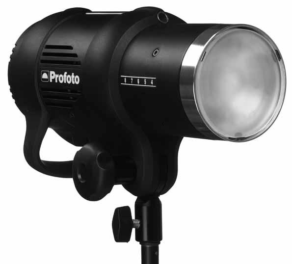
8 Nomenclature Display 2. On Button 3. Power Supply Indicator 4. Test Button 5. Ready Indicator 6. Channel Set Button 7. Setting Knob 8. SLAVE SETTING 8a. Slave Button 8b. RADIO Indicator 8c. IR Indicator 9. READY SETTING 9a. Ready Button 9b. BEEP Indicator 9c. DIM Indicator 10. MODEL SETTING 10a.Model Button 10b.PROP Indicator 10c.FREE Indicator 11. Model Set Button
 16. Locking Knob 17. Zoom Scale 18.")
9 Sync Connector 13. Power Supply (AC) Connector 14. Fuse Holder 15. Umbrella Tube (on the upper side) 16. Locking Knob 17. Zoom Scale 18. Stand Adapter
10 Functionality Power supply The D1 unit can be connected to VAC or VAC, Hz. The unit automatically senses and adapts to the supplied voltage and frequency. The power supply fuses must not be smaller than specified in the section Technical data. 10 Most gas generators with an output of 800 W constant load, or more, can power the D1 unit. Thanks to the two stage SMPS (Switch Mode Power Supply) technology, no ProGas unit is needed. WARNING: Never use ordinary household extension cords to elongate the power cable. They may overheat. Always unwind cord reel extension winders fully before use. Contact your Profoto dealer for proper equipment. Due to the two stage SMPS technology, the D1 could make a audible sound during the recharge cycle. This is fully normal and could be seen as the sign of power being charged into the unit. Energy control The current energy level of the flash light is shown in the Display [1] in f-stop scale. The maximal energy (100%) is shown as 10. The Setting Knob [7] is used to adjust the energy level, in 1/10 f-stop or 1 f-stop increments. Modeling light The Model Button [10a] is used to select one of three modeling light alternatives: PROP: The modeling light intensity is automatically adjusted to correspond to the energy level of the flash light. FREE: The modeling light intensity is manually set, free from any connection to the energy level of the flash light. OFF: No modeling light. The Model Set Button [11], in combination with the Setting Knob [7], is used to change the level of the free modeling light. Sync signaling The D1 unit can be synchronized in different ways; via cable, via infrared (IR) light or via the Profoto Air radio system. The 5 meter sync cable can without restrictions be elongated with a sync extension cable. The Profoto sync interconnection cord or so called hard wiring may be used.
11 The built-in IR receiver senses the flash release as well as IR signals from most IR sync transmitters. The Profoto Air radio system is fully integrated in the D1 Air units, allowing radio synchronization via a Profoto Air Remote or Profoto Air Sync device connected to the camera, or via the Profoto Air USB device connected to a computer with the Profoto Studio Air program. D1 units without integrated Profoto Air functionality can be equipped with a Profoto Air Remote or Profoto Air Sync device acting as receiver, enabling radio synchronization via another Profoto Air Remote or Profoto Air Sync device connected to the camera. Ready signaling Ready signaling is used to indicate when the unit is fully charged. The Ready Button [9a] is used to select one of four ready signaling alternatives: BEEP: A clear beep will sound to indicate that the charging of the unit is completed. This setting also enables the control panel sounds, which indicates that a button is pressed or the Setting Knob is turned. DIM: The modeling light will be turned off when the unit is being charged, and turned on again when the charging is completed. This setting also disables the control panel sounds. BEEP-DIM: The modeling light will be turned off when the unit is being charged, and turned on again when the charging is completed. A clear beep will also sound to indicate that the charging is completed. This setting also enables the control panel sounds. OFF: No ready signal. This setting also disables the control panel sounds. 11 Ready indicator/test function The Ready Indicator [5] is illuminated when the unit is fully charged and ready to flash. The Test Button [4] is used to test that all light settings are correct and that the functionality is as expected. When the Test Button [4] is pressed, the unit will flash and the Ready Indicator [5] will be turned off while recharging. When the charging of the unit is completed, the Ready Indicator [5] will be illuminated again. Flash before ready The Flash before ready function makes it possible to flash before the charging of the unit is ready and fully completed. When a flash is released before the unit is 100% recharged, a long beep will sound, indicating an under exposed frame. Naturally the flash light may not correspond fully to the set value.
12 Remote control Wireless remote control is available for D1 Air units, using the Profoto Air Remote device or the Profoto Air USB device in combination with the Profoto Studio Air software. For more information about remote control, please refer to the User s Guides for Profoto Air Remote or Profoto Air USB/Profoto Studio Air. 12 Color temperature A frosted glass plate is included in the D1 delivery. It gives, in combination with the flash tube, a recommended color temperature for daylight type film. Distinctive color temperature adjustments can be obtained by using glass covers with different coatings. Reflector D1 is equipped with a built-in reflector, providing full control, minimal stray light and maximal light output. By mounting an external reflector and placing it in different positions, using the Zoom Scale [17], several light shapes can be created for each lighting purpose. Umbrella D1 is equipped with an umbrella tube that is suited for most umbrellas on the market. The diameter of the umbrella shaft must be between 7 mm and 8 mm. When an umbrella is used, it is not possible to mount an external reflector at the same time.
13 Operating instructions Stand mounting 1. Mount and fasten the D1 unit on the stand using the locking knob on the Stand Adapter [18]. 2. The unit can be directed upwards/downwards when the Locking Knob [16] is loosened. Fasten the Locking Knob [16] when the unit is correctly directed. Mounting of external reflector 1. Unlock the clasp on the external reflector. 2. Slide the reflector onto the D1 unit. Use the Zoom Scale [17] to place the reflector in the desired position. 3. Secure the reflector by locking the clasp. Umbrella mounting 1. Slide the umbrella shaft into the Umbrella Tube [15] on the D1 unit. 2. After a few centimeters, there will be more friction. Continue to slide the umbrella shaft to optimise the light into the umbrella. Glass cover mounting 1. Ensure that the D1 unit is turned off and that the power cable is not connected. 2. If the unit has been in use, wait five minutes to allow the unit to be fully discharged (the autodump function). 3. Gently remove the frosted glass plate. 4. Carefully fit the glass cover in place. Make sure that the safety pins fit properly into the slot of the glass cover. Power connection 1. Connect the power cable to the Power Supply (AC) Connector [13] on the D1 unit and to the mains power supply outlet. 2. The Power Supply Indicator [3] will be red, indicating that the unit is receiving power but is in standby mode. 3. Press the On Button [2]. 4. The Power Supply Indicator [3] will now be green. Energy level setting 1. Use the Setting Knob [7] to change the energy level of the flash light: Turn the Setting Knob [7] clockwise to increase the energy level in 1/10 f-stop increments and counter-clockwise to decrease. Press and hold down the Setting Knob [7] and turn the knob clockwise to increase the energy in 1 f-stop increments and counter-clockwise to decrease. 13
14 14 Modeling light setting 1. Use the Model Button [10a] to select the modeling light: a. To select proportional modeling light, press and hold down the Model Button [10a] until the PROP Indicator [10b] is illuminated. b. To select free modeling light, press and hold down the Model Button [10a] until the FREE Indicator [10c] is illuminated. The energy level of the latest selected free modeling light setting will be activated. c. To turn off the modeling light, press the Model Button [10a]. Both the PROP Indicator [10b] and the FREE Indicator [10c] will be turned off. Press the Model Button [10a] again to turn on the modeling light. Change the level of the free modeling light: 1. Verify that free modeling light setting is selected (the FREE Indicator [10c] shall be illuminated when the modeling light is turned on). 2. Press the Model Set Button [11]. The Display [1] will start flashing, showing the current energy level of the Free modeling light. 3. While the Display [1] is flashing, use the Setting Knob [7] to change the energy level: a. Turn the Setting Knob [7] clockwise to increase the energy level in 1/10 f-stop increments and counter-clockwise to decrease. b. Press and hold down the Setting Knob [7] and turn the knob clockwise to increase the energy in 1 f-stop increments and counter-clockwise to decrease. 4. Wait until the Display [1] stops flashing. (The Display [1] will now show the energy level of the flash light.) Ready signaling setting 1. Use the Ready Button [9a] to select the ready signaling: a. To select sound signaling, press and hold down the Ready Button [9a] until the BEEP Indicator [9b] is illuminated. b. To select light signaling, press and hold down the Ready Button [9a] until the DIM Indicator [9c] is illuminated. c. To select both sound and light signaling, press and hold down the Ready Button [9a] until both the BEEP Indicator [9b] and the DIM Indicator [9c] are illuminated. d. To turn off the ready signaling, press the Ready Button [9a]. Both the BEEP Indicator [9b] and the DIM Indicator [9c] will be turned off. Press the Ready Button [9a] again to turn on the ready signaling.
15 Sync via cable 1. Connect a sync cord from the camera to the Sync Connector [12] on the D1 unit. Sync via IR 1. Press and hold down the Slave Button [8a] until the IR Indicator [8c] is illuminated. Sync via radio (D1 without Profoto Air) 1. Connect a Profoto Air Remote or Profoto Air Sync device (Receiver) with a cable to the Sync Connector [12] on the D1 unit. 2. Follow the instructions for generators without built-in Profoto Air receiver in the Profoto Air Remote/Profoto Air Sync User s Guide. Sync via radio (D1 with Profoto Air) 1. Press and hold down the Slave Button [8a] until the RADIO Indicator [8b] is illuminated. 2. Select radio channel by following the Radio settings instructions below. 3. Connect a Profoto Air Remote or Profoto Air Sync device to the camera. 4. Follow the instructions for generators with built-in Profoto Air receiver in the Profoto Air Remote/Profoto Air Sync User s Guide. Radio settings (D1 with Profoto Air) For sync via radio, the same radio channel has to be set on the D1 unit and the Profoto Air device or the Profoto Studio Air program. 15 For remote control using Profoto Air Remote, the same radio channel and group have to be set on the D1 unit and the Profoto Air device. For remote control using Profoto Air USB and Profoto Studio Air, the same radio channel has to be set on the D1 unit and in the Profoto Studio Air program. 1. Verify that the RADIO Indicator [8b] is illuminated on the D1 unit. 2. Press the Channel Set Button [6]. The Display [1] will start flashing, showing the current radio channel number to the left and the radio group letter to the right. 3. While the Display [1] is flashing, turn the Setting Knob [7] clockwise to increase the radio channel number (1 to 8) and counter-clockwise to decrease the number. 4. While the Display [1] is flashing, press and hold down and turn the Setting Knob [7] clockwise to increase the group letter (A to F) and counter-clockwise to decrease the letter. 5. Wait until the Display [1] stops flashing. (The Display [1] will now show the energy level of the flash light.) For radio channel and group settings on the Profoto Air devices and the Profoto Studio Air program, please refer to the corresponding User s Guide.
16 Turn off unit All settings will remain when the unit is in standby mode. If the power cable is removed, the modeling light will revert to the default settings; the modeling light will be turned off and the energy level of the free modeling light will be set to Press the On Button [2] to turn off the power. 2. The Power Supply Indicator [3] will be red, indicating that the unit is receiving power but is in standby mode. 3. Remove the power cable. Battery mode The D1 can be set to low power mode enabling it to be supplied by a battery inverter. By reducing the current and using the D1 in battery mode, the Profoto BatPac can supply up to four D1 at the same time. If the D1 are used in standard mode, the BatPac can supply max. two D1 at the same time with a limited performance. Operating instructions To toggle the battery mode, go to standby and press the Model button for 10s. The display will toggle between bt (battery mode) or - - (normal mode). To activate this function, the generator needs to be restarted by removing and reconnecting the mains supply. Power on mode The D1 normally starts to standby when mains are connected. In some cases the user may want the D1 to turn on immediately and this can be done by changing the power on mode. Operating instructions To toggle the power on mode, go to standby and press the Test button for 10s. The display will toggle between P0 (power on to standby) or P1 (power on immediately). The next time the generator is started it will enter the chosen mode. Note! In P1 mode, the generator will go to whatever the generator was set to when mains was last disconnected. If it was in standby, it will go to standby, if it was turned on, it will be turned on. Display mode If the D1 is mounted upside down in a fixed installation, reading the power setting on the display may be awkward. To solve this, the user has the option to change the display mode which will change the orientation of the display. Operating instructions To toggle the display mode, go to standby and press the Slave button for 10s. The display will toggle the letters AA with the right side up, or upside down, indicating the display orientation.

17 Maintenance Changing flash tube and/or modeling lamp 1. Ensure that the D1 unit is turned off and that the power cable is not connected. 2. If the unit has been in use, wait five minutes to allow the unit to be fully discharged. 3. Gently remove the frosted glass plate. 4. Change the flash tube: Unlock the flash tube trigger by unfolding the stainless steel ribbons around the clasp. Grasp the flash tube in the bottom and pull it straight out of the socket. When inserting the new flash tube, ensure that the trigger connection clasps properly around the flash tube. Lock the flash tube trigger by folding the stainless steel ribbons around the clasp. 5. Change the modeling lamp: Pull the lamp straight out of the socket. Insert a new modeling lamp, straight into the socket. Do not touch the lamp with bare hands. 6. Carefully fit the glass plate in place, with the frosted side inwards. Make sure that the safety pins fit properly around the glass plate. 17 Clasp Flash tube Modeling lamp
18 Changing built-in fuse 1. Ensure that the D1 unit is turned off and that the power cable is not connected. 2. If the unit has been in use, wait five minutes to allow the unit to be fully discharged (the autodump function). 3. Pull out the Fuse Holder [14] from the unit and remove the old fuse. 4. Push the new fuse all the way into the Fuse Holder. Only use recommended fuse, see section Technical data. 5. Fit the Fuse Holder in place, by gently pushing until the holder snaps in place. 18
19 Adaptive thermal control The D1 unit is equipped with an adaptive thermal control system. If there is risk for over heating of the unit, caused by either heavy use or abnormal external influence, the thermal control system will automatically protect the unit from damage. A microprocessor supervises and controls the unit, based on input from four thermal sensors. If the sensors report an increase in temperature, the microprocessor automatically takes measures to protect the unit. The first measure is to increase the fan speed. If the fan at full speed cannot bring the temperature down, the modeling light will automatically be turned off during recharging. Next step is to turn off the modeling light completely and at the same time slow down the recharging. Eventually the recharging will stop completely. After a while, when the temperature has decreased sufficiently, the unit will start recharging at a normal pace. This automatic protection will only interfere under extreme conditions, such as when the air vents are blocked. 19 Depending on version, the D1 unit is designed to withstand up to 1000 full power flashes during one hour. However, it is not recommended to run harder than necessary due to the lifetime of the flash tube. If a defective flash head for example with a broken or misfiring flash tube is used, after releasing the flash a long beep signal will indicate malfunction/underexposure. Notice: The air vents of the unit must never be blocked or covered in any way. Never store your flash equipment in a car on a hot and sunny day. Never use a D1 unit that is placed inside a case or transport box. Avoid storing the unit close or below the freezing point. A cold unit may not work properly or may even brake and will lose capacity (flash output). There is also a risk of failure because of condensation when a cold generator is moved to a warmer surrounding. Do not expose any flash equipment to wet or humid environments or extreme electro-magnetic fields.
20 20 Technical data D Air D1 500 Air D1 250 Air D1 500 D1 250 Specifications D Air D1 500 Air D1 500 Energy (Ws/J) D1 250 Air D1 250 Power range f-stop Ws Power range 1/1-1/64 1/1-1/64 1/1-1/64 Power increments 1/10 1/10 1/10 Flash duration t0.5 minmax power 1/700-1/1800 1/1000-1/2600 1/1400-1/3700 Recycling 230V Recycling 120V Color temperature consistency, K +/- 30 +/- 30 +/- 30 Color temperature, K Energy precision (flash-toflash) f-stop Light spread with built-in reflector ±0.05 ±0.05 ± degrees 77 degrees 77 degrees Multi voltage Yes Yes Yes Power supply fuse, VAC Power supply fuse, VAC 6 amp 6 amp 6 amp 10 amp 10 amp 10 amp Built-in fuse T10AH 5x20 T10AH 5x20 T10AH 5x20
21 Specifications D Air D1 500 Air D1 500 D1 250 Air D1 250 Modeling lamp 120V, 300W 120V, 300W 120V, 300W Modeling light function Off, Prop, Free Off, Prop, Free Off, Prop, Free Synchronization modes Sync cable/ir/air Sync cable/ir/air Sync cable/ir/air Measurements Dimensions mm (length & diameter) Dimensions inch (length & diameter) 300 x 130 (170 including Stand Adapter) 11.8 x 5.12 (6.69 including Stand Adapter) 21 Weight 2.94 kg/6.48 lbs 2,43 kg/5,36 lbs 2,23 kg/4,91 lbs All data are to be considered as nominal and Profoto reserves the right make changes without further notice.
22 This page is intentionally left blank.
23 This page is intentionally left blank.
24 Technical data and product information are subject to change without notice Printed in Sweden. Profoto AB P.O. Box 2023 SE Skarpnäck SWEDEN Phone info@profoto.com
ProHead. User s Guide
 ProHead User s Guide 2Profoto ProHead Profoto ProHead Thank you for choosing Profoto. Thanks for showing us your confidence by investing in a ProHead unit. For more than four decades we have sought the
User guide ProHead Plus
 User guide ProHead Plus For other languages visit: /support ProHead Plus 2 Congratulations on your new Profoto product! Thanks for showing us your confidence by investing in a ProHead unit. For more than
AcuteB Head. User s Guide
 User s Guide SAFETY PRECAUTIONS! Read and follow all safety instructions below carefully to avoid injuries or damages! Make sure that this user manual always accompanies equipment! Profoto products are
Acute/D4 Head User s Guide
 Acute/D4 Head User s Guide Guide de Iútilisateur Benutzerhandbuch Manuale Utente Manual del usuario Gebruikershandleiding 用户说明书 Användarhandbok Brukerhåndbok Brugerhåndbog Käyyttöopas 2 Thank you for choosing
Profoto B1 500 AirTTL. User s Guide
 Profoto B1 500 AirTTL User s Guide Profoto B1 500 Air TTL 2 Congratulations on your new Profoto product! Profoto B1 500 Air TTL Regardless if you chose a new flash or a new light-shaping tool, know that
User guide ProRing. For other languages visit:
 User guide ProRing For other languages visit: /support 2 Thank you for choosing Profoto. Follow the instructions in this booklet to use your new product. 3 Thanks for showing us your confidence by investing
D Air D1 500 Air D1 250 Air D1 500 D1 250 User s Guide EN
 D1 1000 Air D1 500 Air D1 250 Air D1 500 D1 250 User s Guide EN This user guide is available in other languages at profoto.com/support CN 其他语言版本的用户指南可从 profoto.com/cn/support 下载 DE Das Bedienungs-Handbuch
ProRing 2 User s Guide
 User s Guide Guide de Iútilisateur Benutzerhandbuch Manuale Utente Manual del usuario Gebruikershandleiding 用户说明书 Användarhandbok Brukerhåndbok Brugerhåndbog Käyyttöopas 2 Thank you for choosing Profoto.
User guide Profoto B1X
 User guide Profoto B1X For other languages visit: B1X 2 Congratulations on your new Profoto product! B1X Regardless if you chose a new flash or a new light shaping tool, know that almost half a century
lighting your creativity HONEY BADGER 320Ws Digital Flash Instruction Manual
 lighting your creativity HONEY BADGER 320Ws Digital Flash Instruction Manual www.interfitphotographic.com Honey Badger 320 Digital Flash What s cool about the Honey Badger? The Honey Badger is the perfect
XMT Location Flash User Guide
 XMT Location Flash User Guide Bowens.co.uk Congratulations on purchasing your new Bowens product. Thank you for choosing the XMT range flash system. The Bowens XMT monolight has been designed by working
impact VC-500LR Monolight INSTRUCTIONS
 impact lighting equipment and accessories VC-500LR Monolight INSTRUCTIONS Congratulations on your purchase of the Impact VC-500LR Monolight. We feel that it will contribute much to your photographic skill
The Interfit S1. AC/DC Powered TTL/HSS Flash. Instruction Manual.
 The Interfit S1 AC/DC Powered TTL/HSS Flash Instruction Manual www.interfitphotographic.com Interfit S1 Battery Powered TTL/HSS Flash Unit What s cool about the Interfit S1? The S1 is the world s first
Instruction Manual. Compact Studio Flash
 Instruction Manual Compact Studio Flash FOREWORD Thanks for choosing LUMI series studio flash. It is a durable and good quality strobe with complete functions to help photographers create desired lighting
The Interfit S1 Battery Powered TTL/HSS Flash
 The Interfit S1 Battery Powered TTL/HSS Flash Instruction Manual www.interfitphotographic.com Interfit S1 Battery Powered TTL/HSS Flash Unit What s cool about the Interfit S1? The Honey Badger is the perfect
Acute2 manual Profoto, Stockholm, Sweden.
 Acute2 manual Profoto, Stockholm, Sweden. Warning Profoto generators and lamp heads are parts of a complete professional lighting system. Please read the instruction manual carefully before use. Flash
QUANTUM Qflash T2 / X2 OPERATING INSTRUCTIONS
 QUANTUM Qflash T2 / X2 OPERATING INSTRUCTIONS 1.0 DESIGNATIONS T2 AND X2 1. Removable Reflector, two positions Normal and Wide angle. 2. Flash-tube 2A. Modeling Lamp (for Model X2 only) 3. Bounce Head,
INSTRUCTION MANUAL. Starter SK studio flash
 INSTRUCTION MANUAL Starter SK-200 studio flash www.dynaphos.com 1 Savety Thank you for choosing DYNAPHOS studio lighting equipment! Before you proceed further, please read the instruction manual. Use of
D1 Air The new Profoto compact
 D1 Air 2 3 D1 Air The new Profoto compact Professional photographers today need durable, tough, fast and consistant flash units suited for digital photography and demanding assignments. Profoto is well
PROMASTER PRM SERIES REMOTE MONOLIGHTS
 PROMASTER PRM SERIES REMOTE MONOLIGHTS are full-featured high power studio monolights with a full function remote control that offers you the ultimate convenience of controlling all of the flash functions
D1 Air The new Profoto compact
 D1 Air 2 3 D1 Air The new Profoto compact Professional photographers today need durable, tough, fast and consistant flash units suited for digital photography and demanding assignments. Profoto is well
QUANTUM Qflash MODEL T OPERATING INSTRUCTIONS
 QUANTUM Qflash MODEL T OPERATING INSTRUCTIONS 1.0 DESIGNATIONS 1. Removable Reflector, two positions Normal and Wide angle. 2. Flash-tube 3. Bounce Head, Rotates 180º 4. Swivel Head, Rotates ± 90º 5. Sensor
For Your Safety. Foreword
 User Manual Foreword For Your Safety Before using this product Please read this user manual carefully in order to ensure your safety and the proper operation of this product. Keep for future reference.
Tube Facing Tool.
 www.swagelok.com Tube Facing Tool This manual contains important information for the safe and effective operation of the Swagelok TF72 series tube facing tool. Users should read and understand its contents
tough lightweight clever Instructions for use 300 &
 tough lightweight clever Instructions for use 300 & 600 0845 618 2889 Congratulations! Welcome to our lightweight super tough elitepro2. The instructions in this manual apply to both our 300Ws and 600Ws
USER GUIDE. Studio Flash Kit NS-DACMSFK/NS-DACMSFK-C. Before using your new product, please read these instructions to prevent any damage.
 USER GUIDE Studio Flash Kit NS-DACMSFK/NS-DACMSFK-C Before using your new product, please read these instructions to prevent any damage. Studio Flash Kit Contents IMPORTANT SAFETY INSTRUCTIONS..............................................................
User guide Profoto B10
 User guide For other languages visit: /support 2 Congratulations on your new Profoto product! Regardless if you chose a new flash or a new light shaping tool, know that almost half a century s worth of
DM 800H Twin Handheld UHF System (863.0Mhz-865.0Mhz)
") DM 800H Twin Handheld UHF System (863.0Mhz-865.0Mhz) User Manual Order code: MIC78 Safety advice WARNING FOR YOUR OWN SAFETY, PLEASE READ THIS USER MANUAL CAREFULLY BEFORE YOUR INITIAL START-UP! Before
DM 800H Twin Handheld UHF System (863.0Mhz-865.0Mhz) User Manual Order code: MIC78 Safety advice WARNING FOR YOUR OWN SAFETY, PLEASE READ THIS USER MANUAL CAREFULLY BEFORE YOUR INITIAL START-UP! Before
Pro-B Air. User s Guide
 Pro-B4 1000 Air User s Guide Pro-B4 1000 Air 2 Thank you for choosing Profoto Pro-B4 1000 Air Thanks for showing us your confidence by investing in a Pro- B4 generator. For more than four decades we have
School of Digital Media Arts GM 300BB
 Washtenaw Community College Don Werthmann School of Digital Media Arts GM 300BB 973.3586 http://courses.wccnet.edu/~donw donw@wccnet.edu Introduction to Profoto Acute 2 Strobe Lighting System The transition
SAGA PRO SERIES STEREO POWER AMPLIFIER OPERATION MANUAL
 SAGA PRO SERIES STEREO POWER AMPLIFIER OPERATION MANUAL INSTALLATION Use care in unpacking the amplifier, and be sure to save the carton and packing materials so that you can use them for moving, storing,
creative image lighting technology
 creative image lighting technology RX FAMILY D-Lite RX studio flash is the entry range of the Elinchrom studio flash family. Whether you are new to lighting, already have speedlights or just want to take
2015 RIGOL TECHNOLOGIES, INC.
 Service Guide DG000 Series Dual-channel Function/Arbitrary Waveform Generator Oct. 205 TECHNOLOGIES, INC. Guaranty and Declaration Copyright 203 TECHNOLOGIES, INC. All Rights Reserved. Trademark Information
Inspiration strikes. VS-210 FLASH. User s Manual
 Inspiration strikes. VS-210 FLASH User s Manual Copyright 2015 Gradus Group. Bolt and other names of Bolt products are trademarks of Gradus Group. Other product and corporate names mentioned herein are
TMP40. User Manual.
 TMP40 User Manual www.audac.eu ADDITIONAL INFORMATION This manual is put together with much care, and is as complete as could be on the publication date. However, updates on the specifications, functionality
Profoto B1 500 AirTTL User s Guide EN
 Profoto B1 500 AirTTL User s Guide EN This user guide is available in other languages at profoto.com/support CN 其他语言版本的用户指南可从 profoto.com/cn/support 下载 DE Das Bedienungs-Handbuch is auch in anderen Sprachen
EPA152/252/502. User Manual.
 EPA152/252/502 User Manual www.audac.eu ADDITIONAL INFORMATION This manual is put together with much care, and is as complete as could be on the publication date. However, updates on the specifications,
2.4G Wireless FlashTTL Trigger KR-201
 2.4G Wireless FlashTTL Trigger KR-201 Contents Contents About high performance of KR201 Cautions before use KR201 of remote functions Compatible equipment The name of each part The basic installation instructions
R PROFLAME Instruction Book Collection
 9.956.028 R00 584 PROFLAME Instruction Book Collection 4-17 18-29 584 PROFLAME System 30-39 Appendix: DIP SWITCH NUMBER (0=ON 1=OFF) 40-41 4-17 Fig. 1 The SIT is a device that allows, in conjunction with
DMP40. User Manual.
 DMP40 User Manual www.audac.eu ADDITIONAL INFORMATION This manual is put together with much care, and is as complete as could be on the publication date. However, updates on the specifications, functionality
BATTERY GRIP INSTRUCTION MANUAL
 BG-D700 BG-D90 BATTERY GRIP INSTRUCTION MANUAL Product Diagram 1- Contact Cap 2- Holder for Nikon dslr Signal Contact Cover 3- Signal Contacts 4- Auto-Focus Button 5- Main Control Dial 6- Multi-Selector
OLED-55 USER MANUAL OCTALUX LED. OctaLux LED - USER MANUAL 1
 OLED-55 OCTALUX LED USER MANUAL OctaLux LED - USER MANUAL 1 OctaLux LED INTRODUCTION Thank you for choosing Genaray. The OctaLux LED Light Softbox produces bright, soft, and consistent light that s designed
CANARY AUDIO. Power Amplifier CA-309 OWNER S MANUAL. Handcrafted in California MADE IN USA
 CANARY AUDIO 300B Push-Pull Parallel Power Amplifier Mono Block Handcrafted in California CA-309 OWNER S MANUAL MADE IN USA Dear Customer: Please allow us to take this opportunity to thank you for purchasing
3x Magnification. Digital Zoom to 6x. CAUTION: Do not point Infrared Emitter directly into eye at close range.
 MxGenPRO MANUAL-English.qx_MxGenPRO Manual-English 12/16/14 9:24 AM Page 3 Instruction Manual 3x Magnification. Digital Zoom to 6x. CAUTION: Do not point Infrared Emitter directly into eye at close range.
DPAfour125, DPAfour250 AMPLIFIERS. Operating Manual
 DPAfour125, DPAfour250 AMPLIFIERS Operating Manual Operating manual, DPA Series DPA-10UMS01-V01R04 version revision date 01 02 24-02-2012 www.ateis-europe.com ATEÏS Europe BV - Sydneystraat 42-3047BP ROTTERDAM
X-Series WHITE WHITE LIGHTNING TM. The White Lightning TM X-Series Operation Manual
 WHITE LIGHTNING TM X-Series The White Lightning TM X-Series Operation Manual The X-Series Flash Units are manufactured and directly sold by White Lightning TM, a division of Paul C. Buff, Inc. TM, and
English User's Guide
 User's Guide Imacon Flextight 343 2 2003 Imacon A/S. All rights reserved. Imacon Flextight 343 User's Guide, Part No 70030009, revision B. The information in this manual is furnished for informational
Safety Warnings Features Specifications Instrument Layout Operation Preparation AC Current Measurement How to Use Peak Hold Function How to Use The
 Safety Warnings Features Specifications Instrument Layout Operation Preparation AC Current Measurement How to Use Peak Hold Function How to Use The Frequency Selector Switch How to Use Data Hold Function
FOLDING MACHINE PF-45A OPERATOR MANUAL 1. FUNCTION
 FOLDING MACHINE OPERATOR MANUAL 1. FUNCTION The folding machine is used to fold documents stand alone or in combination with a system 7. Sheets can be folded in various types. These are: single fold; letter
User instructions Metallurgical inverted microscope
 KERN & Sohn GmbH Ziegelei 1 D-72336 Balingen E-mail: info@kern-sohn.com Tel: +49-[0]7433-9933-0 Fax: +49-[0]7433-9933-149 Internet: www.kern-sohn.com User instructions Metallurgical inverted microscope
Thank you very much for choosing Shuguang Audio Classic Series vacuum tube amplifier
 Thank you very much for choosing Shuguang Audio Classic Series vacuum tube amplifier (845 version). When opening the package, please carefully unpack all tubes and install each tube to its marked location
Operation Manual. Congratulations on purchasing your high quality AIMS Power pure sine inverter!
 Operation Manual Congratulations on purchasing your high quality AIMS Power pure sine inverter! It is very important that you read and understand this instruction manual completely prior to use. Contained
PHOTO FRAME STRING LIGHTBOXES
 PFL-500CD PHOTO FRAME STRING LIGHTBOXES Candlenut Distressed Wood Frame USER MANUAL NEED HELP? Call our help line 1-866-765-3686 or visit us at: www.polaroidlightboxes.com Polaroid, Polaroid & Pixel, Polaroid
PhotoMaster. Operator s Manual. For
 PhotoMaster Operator s Manual For Voltage Smart PhotoMaster PM400 Voltage Smart PhotoMaster PM800 Voltage Smart PhotoMaster PM400R Voltage Smart PhotoMaster PM800R & Remote Studio Control Accessories OPERATOR
Pro-8a 2400 Air Pro-8a 1200 Air User s Guide EN
 Pro-8a 2400 Air Pro-8a 1200 Air User s Guide EN This user guide is available in other languages at profoto.com/support CN 其他语言版本的用户指南可从 profoto.com/cn/support 下载 DE Das Bedienungs-Handbuch is auch in anderen
IP Series DUAL POWER AMPLIFIERS
 OPERATING INSTRUCTIONS IP Series DUAL POWER AMPLIFIERS IP-600D IP-450D IP-300D TABLE OF CONTENTS 1. SAFETY PRECAUTIONS... 2 2. GENERAL DESCRIPTION... 4 3. FEATURES... 4 4. HANDLING PRECAUTIONS... 4 5.
DC162 Digital Visualizer. User Manual. English - 1
 DC162 Digital Visualizer User Manual English - 1 Chapter 1 Precautions Always follow these safety instructions when setting up and using the Digital Visualizer: 1. Please do not tilt the machine while
AC 3. Active Antenna Combiner. Instruction manual
 AC 3 Active Antenna Combiner Instruction manual Contents Contents Important safety instructions... 2 The AC 3 active transmitter combiner... 4 Delivery includes... 4 Operating controls... 5 Block diagram...
F100 Tabletop Document Folder
 F100 Tabletop Document Folder 10/2018 OPERATOR MANUAL FIRST EDITION Single Fold Letter Fold Z-fold Double Fold Specifications Paper size 11" & 14" Paper weight 60g/m 2 to 90g/m 2 Some recycled paper and
VE-TTL. Venture TTL 600 Ws Monolight Kit INSTRUCTIONS
 VE-TTL Venture TTL 600 Ws Monolight Kit INSTRUCTIONS Introduction 2 Thank you for choosing Impact. The Venture TTL-600 is a professional monolight that s powered by a powerful lithium-ion battery. It features
i3speakers LX503 MK2 User Manual
 i3speakers LX503 MK2 User Manual Index Introduction 5 Precautions 6 Safety requirements 6 Caution servicing 7 EC Declaration of Conformity 7 Waste of Electrical and Electronic Equipment (WEEE) 7 Chapter
INSTRUCTION MANUAL INF Fax: (503)
") INSTRUCTION MANUAL INF151 1-800-547-5740 Fax: (503) 643-6322 www.ueiautomotive.com email: info@ueitest.com Introduction Congratulations on your purchase of the INF151 infrared thermometer. Like all UEi
INSTRUCTION MANUAL INF151 1-800-547-5740 Fax: (503) 643-6322 www.ueiautomotive.com email: info@ueitest.com Introduction Congratulations on your purchase of the INF151 infrared thermometer. Like all UEi
USER MANUAL ENGLISH 1450 COIN COUNTER & SORTER
 USER MANUAL ENGLISH 1450 COIN COUNTER & SORTER INTRODUCTION ENGLISH Thank you for purchasing the Safescan 1450 coin counter and sorter. For proper use and maintenance, we advise to read this user manual
Profoto Air Remote TTL-C. User s Guide
 Profoto Air Remote TTL-C User s Guide AIr Remote TTL-C 2 Congratulations on your new Profoto product! Air Remote TTL-C Regardless if you chose a new flash or a new light-shaping tool, know that almost
MBM 307A / 407A PF Automatic Folders
 MBM 307A / 407A PF Automatic Folders Instruction Manual Provided By http://www.mybinding.com http://www.mybindingblog.com OPERATION MANUAL MBM 307A / 407A AUTOMATIC FOLDERS 1-800-223-2508 www.mbmcorp.com
REVAMP4120T Instruction manual
 REVAMP4120T Instruction manual REVAMP4120T Instruction manual 3 REVAMP4120T manual 4 CLASS-D POWER AMPLIFIER IMPORTANT SAFETY INSTRUCTIONS 1. Read these instructions 2. Keep these instructions 3. Pay
M-300 Mono power amplifier User s guide
 M-300 Mono power amplifier User s guide M-300 Mono power amplifier User s guide Specifications: Contents: Power output: 8Ω: 290W, 0.01% THD SPECIFICATIONS Page 2 Input impedance: Gain: 4Ω: 580W, 0.01%
Mixer Amplifier series
 Mixer Amplifier series with MP & FM Tuner User Manual MA MP MIXER AMPLIFIER MIC MIC AUX US B/S D/F M BASS - - + - + + - + - - + - TREBLE + - AUX MIC/LINE + + - MIXER + MA MP + - AMPLIFIER MIC MIC AUX MIC/LINE
EPA104/254. User Manual.
 EPA104/254 User Manual www.audac.eu ADDITIONAL INFORMATION This manual is put together with much care, and is as complete as could be on the publication date. However, updates on the specifications, functionality
for Canon/ Nikon digital SLR cameras INSTRUCTION MANUAL
 for Canon/ Nikon digital SLR cameras INSTRUCTION MANUAL Thank you for purchasing a Nissin product Before using this flash unit, please read this instruction manual and refer your camera owner s manual
Safety Warnings Features Specifications Instrument Layout Operation Preparation AC Current Measurement How to Use Peak Hold Function How to Use The
 Safety Warnings Features Specifications Instrument Layout Operation Preparation AC Current Measurement How to Use Peak Hold Function How to Use The Frequency Selector Switch How to Use Data Hold Function
IEM 200 R UHF receiver. user manual
 IEM 200 R UHF receiver user manual Musikhaus Thomann Thomann GmbH Hans-Thomann-Straße 1 96138 Burgebrach Germany Telephone: +49 (0) 9546 9223-0 E-mail: info@thomann.de Internet: www.thomann.de 17.11.2015,
99 Washington Street Melrose, MA Fax TestEquipmentDepot.com # # AAC Clamp Meter. Instruction Manual
 99 Washington Street Melrose, MA 02176 Fax 781-665-0780 TestEquipmentDepot.com #61-732 #61-736 400 AAC Clamp Meter Instruction Manual AC HOLD APO DC KMΩ mva WARNING Read First: Safety Information Understand
15" 500W self-powered subwoofer
 15" 500W self-powered subwoofer USER GUIDE 10349 - Version 1 /01-2015 English SRSUB15A - 15" 500W self-powered subwoofer 1 - Safety information Important safety information This unit is intended for indoor
Premium Soldering station
 www.jbctools.com English Premium Soldering station Ref. DIT-D 2 www.jbctools.com Packing List The following items should be included: DI Control Unit... 1 unit Stand... 1 unit Sponge... 1 unit Cartridge...
USER'S GUIDE. EcoQuest International 310 T. Elmer Cox Drive Greeneville, TN (423) Setup. Operation. Specifications.
 Setup. Operation. Specifications.") USER'S GUIDE Setup Operation Specifications Warranty (43) 638-746 CAUTION: Read manual carefully for proper procedures and operation. CONTENTS SPECIFICATIONS Specifications...............................................................3
USER'S GUIDE Setup Operation Specifications Warranty (43) 638-746 CAUTION: Read manual carefully for proper procedures and operation. CONTENTS SPECIFICATIONS Specifications...............................................................3
User Manual. ilive 2 Wireless microphone system
 User Manual ilive 2 Wireless microphone system Safety instructions When using this electronic device, basic precautions should always be taken, including the following: 1 Read all instructions before using
SL Slave Amplifiers. User Manual. Order codes: CRAM37 - SL V 4 x 60W CRAM22 - SL V 4 x 120W CRAM23 - SL V 4 x 240W
 SL Slave Amplifiers User Manual Order codes: CRAM SL V x W CRAM SL V x W CRAM SL V x W Safety advice WARNING FOR YOUR OWN SAFETY, PLEASE READ THIS USER MANUAL CAREFULLY BEFORE YOUR INITIAL STARTUP! Before
Wireless SingStar Microphone Instruction Manual
 Wireless SingStar Microphone Instruction Manual 2008 Sony Computer Entertainment Europe. SingStar is a trademark or a registered trademark of Sony Computer Entertainment Europe. 2, PLAYSTATION and PlayStation
User instructions Compound laboratory microscope
 KERN & Sohn GmbH Ziegelei 1 D-72336 Balingen E-mail: info@kern-sohn.com User instructions Compound laboratory microscope Tel: +49-[0]7433-9933-0 Fax: +49-[0]7433-9933-149 Internet: www.kern-sohn.com KERN
REVAMP4100 Instruction manual
 REVAMP4100 Instruction manual REVAMP4100 Instruction manual 3 REVAMP4100 manual 4 CLASS-D POWER AMPLIFIER IMPORTANT SAFETY INSTRUCTIONS 1. Read these instructions 2. Keep these instructions 3. Heed all
EM420A/420B DIGITAL MULTIMETER OWNERS MANUAL Read this owners manual thoroughly before use
 http://www.all-sun.com EM420A/420B DIGITAL MULTIMETER OWNERS MANUAL V Read this owners manual thoroughly before use WARRANTY This instrument is warranted to be free from defects in material and workmanship
INSTALLATION HANDBOOK
 Replacing Consumables Replacing the Lamps Lamp replacement period It is time to replace the lamp when: The message "Replace the lamp." is displayed at the lower left of the projection screen when you start
APA3-1500R STARTER SET WIRELESS SWITCHING
 COMPATIBILITY This set can be combined with all trust smart home transmitters and receivers. TECHNICAL SPECIFICATIONS RECEIVER Power supply input Maximum load RF frequency RF range Memory addresses 3 220-240
Allegro Home Office Assembly Instructions. Tipping Restraint. Bun Foot W/ Leveler. 4 pcs.
 email: info@riverside-furniture.com Allegro Home Office Assembly Instructions Components and Hardware List Page 1 of 5 Made in China Shelf Pin Wood Shelf File Rod & Clips 1/2"Wood Screw A 16 pcs. B 4 pcs.
Important Safety Information
 OWNER'S MANUAL Important Safety Information 1. Read these instructions. 2. Keep these instructions. 3. Heed all warnings. 4. Follow all instructions. 5. Do not use this apparatus near water. 6. Clean only
ML7520 ML7530 DIOPTER ADJUSTMENT RING BINOCULAR BODY, INCLINED 30. (a) Field Iris Control Lever. (c) Filter Slots EYEPIECES, KHW10X
 Field Iris Control Lever. (c) Filter Slots EYEPIECES, KHW10X") JAPAN DIOPTER ADJUSTMENT RING BINOCULAR BODY, INCLINED 30 (a) Field Iris Control Lever (c) Filter Slots EYEPIECES, KHW10X ANALYZER CONTROL LEVER (b) Aperture Iris Control Lever LIGHT SOURCE HOUSING VERTICAL
JAPAN DIOPTER ADJUSTMENT RING BINOCULAR BODY, INCLINED 30 (a) Field Iris Control Lever (c) Filter Slots EYEPIECES, KHW10X ANALYZER CONTROL LEVER (b) Aperture Iris Control Lever LIGHT SOURCE HOUSING VERTICAL
Digital Color Printer
 3-858-635-12 (1) Digital Color Printer Operating Instructions Before operating the unit, please read this manual thoroughly and retain it for future reference. This PRINTER is designed to use PRINT PACK
For the 50 years of BALCAR, we are pleased to announce a new line of generators, fully compatible with a complete digital workflow process.
 For the 50 years of BALCAR, we are pleased to announce a new line of generators, fully compatible with a complete digital workflow process. BALCAR products are known for their high technology in particular
Always there to help you. Register your product and get support at AJ3200. Question? Contact Philips.
 Always there to help you Register your product and get support at www.philips.com/support Question? Contact Philips AJ3200 User manual Contents 1 Important 2 Safety 2 2 Your clock radio 3 Introduction
JJC. Electronic Speedlight SF-33. Instruction Manual
 JJC EN Electronic Speedlight SF-33 Instruction Manual Contents For your safety...1 WARNINGS for flash...2 WARNINGS for batteries...3 Flash parts and their functions...4-6 Installing the batteries...7 Attach
MS8268 HANDHELD DIGITAL MULTIMETER OPERATOR S INSTRUCTION MANUAL
 MS8268 HANDHELD DIGITAL MULTIMETER OPERATOR S INSTRUCTION MANUAL Table of Contents TITLE PAGE 1. GENERAL INSTRUCTIONS 1 1.1 Precaution safety measures 1 1.1.1 Preliminary 1 1.1.2 During use 2 1.1.3 Symbols
SAFETY AND OPERATING MANUAL
 SAFETY AND OPERATING MANUAL BladeRunner X2 WX572 9 10 8 11 5 7 12 6 20 1 2 4 3 14 13 15 A2 A1 17 18 B2 B1 1 2 1 2 19 B3 3 4 2 C 1 D1 D1 C 2 1 E1 D2 1 2 E2 1 2 F G1 G1 F OFF ON G2 G3 H1 H2 I1 I2 I1 I2 J
LW5 LB5 LW10 LB10 QUICKSTART GUIDE. Lyra Daylight LED Half x 1 Soft Light. Lyra Bi-Color LED Half x 1 Soft Light. Lyra Daylight LED 1x1 Soft Light
 QUICKSTART GUIDE LW5 Lyra Daylight LED Half x 1 Soft Light LB5 Lyra Bi-Color LED Half x 1 Soft Light LW10 Lyra Daylight LED 1x1 Soft Light LB10 Lyra Bi-Color LED 1 x 1 Soft Light 2016 ikan Corporation.
FD 125 Large-Format Card Cutter
 FD 125 Large-Format Card Cutter 3/201 OPERATOR MANUAL Page 2 Table of Contents SAFETY PRECAUTIONS... 4 Introduction... 5 Specifications... 5 Accessories... 5 Major Components and Assemblies... 6 Control
ELPMB27. Short Throw Projector Wall Mount Installation Manual xxx(fr) xxx(de) xxx(it) xxx(es) xxx(pt) xxx(zhs)
 xxx(de) xxx(it) xxx(es) xxx(pt) xxx(zhs)") ELPMB27 Short Throw Projector Wall Mount Installation Manual xxx(fr) xxx(de) xxx(it) xxx(es) xxx(pt) xxx(zhs) Safety Instructions Before using the wall mount, make sure you read all of the safety instructions
ELPMB27 Short Throw Projector Wall Mount Installation Manual xxx(fr) xxx(de) xxx(it) xxx(es) xxx(pt) xxx(zhs) Safety Instructions Before using the wall mount, make sure you read all of the safety instructions
DC155 Digital Visualizer. User Manual
 DC155 Digital Visualizer User Manual Table of Contents CHAPTER 1 PRECAUTIONS... 4 CHAPTER 2 PACKAGE CONTENT... 6 CHAPTER 3 PRODUCT OVERVIEW... 7 3.1 PRODUCT INTRODUCTION... 7 3.2 I/O CONNECTION... 8 3.3
VFSC9 ELECTRONIC SPEED CONTROLLER. Mounting and operating instructions
 ELECTRONIC SPEED CONTROLLER Mounting and operating instructions Table of contents SAFETY AND PRECAUTIONS 3 PRODUCT DESCRIPTION 4 ARTICLE CODES 4 INTENDED AREA OF USE 4 TECHNICAL DATA 4 STANDARDS 5 WIRING
E-400 power amplifier. user manual
 E-400 power amplifier user manual Musikhaus Thomann e.k. Treppendorf 30 96138 Burgebrach Germany Telephone: (09546) 9223-0 E-mail: info@thomann.de Internet: www.thomann.de 07.03.2014, ID: 173888 Table
User manual UV Flash Dry 15/700. HENSEL-VISIT GmbH & Co. KG Robert-Bunsen-Str. 3 D Würzburg GERMANY
 User manual UV Flash Dry 15/700 HENSEL-VISIT GmbH & Co. KG Robert-Bunsen-Str. 3 D-97076 Würzburg GERMANY Tel. +49 (0) 931 27881-0 Fax: +49 (0) 931 27881-50 Email: info@hensel.de Internet: http://www.hensel.de