UNITED STATES PATENT AND TRADEMARK OFFICE BEFORE THE PATENT TRIAL AND APPEAL BOARD. EDWARDS LIFESCIENCES CORPORATION, Petitioner
|
|
|
- Deborah Cobb
- 5 years ago
- Views:
Transcription
1 Filed on behalf of: Edwards Lifesciences Corporation By: Craig S. Summers Brenton R. Babcock Christy G. Lea Cheryl T. Burgess KNOBBE, MARTENS, OLSON & BEAR, LLP 2040 Main Street, 14th Floor Irvine, CA Tel.: (949) Fax: (949) UNITED STATES PATENT AND TRADEMARK OFFICE BEFORE THE PATENT TRIAL AND APPEAL BOARD EDWARDS LIFESCIENCES CORPORATION, Petitioner v. BOSTON SCIENTIFIC SCIMED, INC., Patent Owner Case No. IPR Patent 6,915,560 PETITION FOR INTER PARTES REVIEW OF U.S. PATENT NO. 6,915,560
2 TABLE OF CONTENTS Page No. I. SUMMARY OF THE ISSUE PRESENTED... 1 II. INTRODUCTION TO THE STATE OF THE ART... 9 III. MANDATORY NOTICES UNDER 37 C.F.R. 42.8(a)(1) A. Real Party-in-Interest (37 C.F.R. 42.8(b)(1)) B. Related Matters (37 C.F.R. 42.8(b)(2)) C. Lead and Back-up Counsel Under 37 C.F.R. 42.8(b)(3) D. Service Information Under 37 C.F.R. 42.8(b)(4) IV. GROUNDS FOR STANDING UNDER 37 C.F.R (a) V. U.S. PATENT NO. 6,915, A. Specification and Claims B. Prosecution History October 22, 2003 Office Action and Response April 22, 2004 Office Action and Response October 19, 2004 Office Action and Response VI. IDENTIFICATION OF CHALLENGE PURSUANT TO 37 C.F.R (B) VII. PERSON HAVING ORDINARY SKILL IN THE ART VIII. CLAIM CONSTRUCTION AND RELATED ISSUES A. A stent crimper comprising B. Dies and blades i-
3 TABLE OF CONTENTS (cont d) Page No. C. Stationary end-walls and stationary plates IX. THE PRIOR ART A. Analogous Art Field Of Endeavor Pertinent To The Particular Problem B. Applicant s Admitted Prior Art C. Yasumi D. Morales X. STATEMENT OF THE PRECISE RELIEF REQUESTED AND THE REASONS FOR CANCELLATION (37 C.F.R (a) AND (b)) A. Claims 1, 2, 6, 8-10, 14, 15, 18, 23, 25, 27, 28, 31, 33, 37, and 40 Are Invalid As Obvious Over Yasumi In View Of The AAPA Claim Claim Claim Claim Claim Claim Claims 2 and ii-
4 TABLE OF CONTENTS (cont d) Page No. 8. Claims 6 and Claims 8, 25, and Claims 9, 14, 23, and Reason, Basis, or Motivation to Combine B. Ground 2: Claims 11, 17, 19, 26, 34, 35, and 39 Are Obvious Over Yasumi In View Of the AAPA and Morales Claim Claims 11, 19, and Claims 17, 26, and Reason, Basis, or Motivation to Combine XI. THIS PETITION IS NOT REDUNDANT UNDER 35 U.S.C. 325(D) XII. SECONDARY CONSIDERATIONS CANNOT OVERCOME THE STRONG EVIDENCE OF OBVIOUSNESS XIII. CONCLUSION iii-
5 TABLE OF AUTHORITIES Page No(s). Allied Erecting & Dismantling Co. v. Genesis Attachments, LLC, No , slip op. (Fed. Cir. June 15, 2016) Boston Scientific Corp. and Boston Scientific Scimed, Inc. v. Edwards Lifesciences Corp., Civil Action No. 8:16-cv-0730 (C.D. Cal.) In re Casey, 370 F.2d 576 (C.C.P.A. 1967) Catalina Marketing International, Inc. v. Coolsavings.com, Inc., 289 F.3d 801 (Fed. Cir. 2002)... 31, 32 In re Clay, 966 F.2d 656 (Fed. Cir. 1992) In re Cuozzo Speed Techs., LLC, 793 F.3d 1268 (Fed. Cir. 2015), aff d, 136 S. Ct (2016) Innovention Toys, LLC v. MGA Entm't, Inc., 637 F.3d 1314 (Fed. Cir. 2011) Intri-Plex Tech., Inc. v. Mmi Holdings Saint-Gobain Performance Plastics Rencol Ltd., IPR Leapfrog Enters., Inc. v. Fisher-Price, Inc., 485 F.3d 1157 (Fed. Cir. 2007) Newell Cos., Inc. v. Kenney Mfg. Co., 864 F.2d 757 (Fed. Cir. 1988) OTHER AUTHORITIES 35 U.S.C , 47, U.S.C , 80 -iv-
6 TABLE OF AUTHORITIES (cont d) Page No(s). 35 U.S.C U.S.C C.F.R , 15, C.F.R C.F.R C.F.R , C.F.R , 30, 49 -v-
7 EXHIBIT LIST Exhibit No. Description 1101 U.S. Patent No. 6,915,560 ( the 560 patent ) 1102 U.S. Patent No. 6,915,560 File History Excerpts 1103 U.S. Patent No. 4,454,657 ( Yasumi ) 1104 U.S. Patent No. 5,893,852 ( Morales ) 1105 Declaration of Neil Sheehan in Support of Petition for Inter Partes Review of U.S. Patent No. 6,915, Curriculum Vitae of Neil Sheehan 1107 Materials Considered by Neil Sheehan 1108 German Patent No. DE9034 ( Nix ) 1109 Certified Translation of Nix 1110 U.S. Patent No. 2,664,996 ( Andrews ) 1111 U.S. Patent No. 4,308,744 ( Baker ) 1112 International Patent Publication No. WO A1 ( Hartley ) 1113 U.S. Patent No. 5,918,511 ( Sabbaghian ) 1114 U.S. Patent No. 6,364,870 ( Pinchasik ) 1115 U.S. Patent No. 5,261,263 ( Whitesell ) 1116 U.S. Patent No. 3,695,087 ( Tuberman ) 1117 U.S. Patent No. 6,176,116 ( Wilhelm ) -vi-
8 Exhibit No. Description 1118 U.S. Patent No. 6,051,002 ( Morales 2 ) 1119 U.S. Patent No. 5,951,540 ( Verbeek ) 1120 U.S. Patent No. 7,892,201 ( Laguna ) 1121 U.S. Patent No. 6,125,523 ( Brown ) 1122 U.S. Patent No. 3,370,451( Schuetz ) 1123 U.S. Patent No. 3,154,978 ( Baker 2 ) 1124 U.S. Patent No. 3,417,598 ( Valente ) 1125 U.S. Patent No. 6,074,381 ( Dinh ) -vii-
9 Edwards Lifesciences Corporation ( Petitioner ) requests inter partes review pursuant to 35 U.S.C and 37 C.F.R et seq. of Claims 1, 2, 6, 8-11, 14, 15, 17-19, 23, 25-27, 28, 31, 33-35, 37, 39 and 40 of U.S. Patent No. 6,915,560 ( the 560 patent ), owned by Boston Scientific Scimed, Inc. ( Patent Owner ). I. SUMMARY OF THE ISSUE PRESENTED The claims of the 560 patent recite a device for crimping a stent onto a balloon catheter. The claimed device has three basic features: (a) movable blades or dies arranged to form a variable-sized polygonal aperture, (b) a rotatable actuation device coupled to the blades or dies, and (c) stationary end-walls on either sides of the blades or dies. By moving the dies, the size of the aperture can be increased (Fig. 2a) or decreased (Fig. 2b) while maintaining the same polygonal shape throughout. -1-
10 Polygonal Aperture 118 Movable Dies 106 Ex Figure 4a is a partial front view that shows the dies, portions of the rotatable actuation device, and one end-wall. As the dies move, the sides of the dies push or squeeze the stent into a smaller size. 1 For clarity, the Figures in this Petition have been colored and annotated. -2-
11 Rotatable Actuation Plate 142 Die 106 Stationary End-wall 156 There was nothing inventive about such a device at the time of the 560 patent s earliest possible priority date of September 22, As the 560 patent admits, a stent crimper with dies coupled to a rotatable actuation device 28 and between stationary end-walls was already well known in the art. Ex at 1:62-2:21 (describing prior art Figure 1). The 560 patent illustrates and describes the following admitted prior art stent crimper that embodies each of these well-known features: -3-
12 Rotatable Actuation Device 28 Dies Stationary End-walls Id., Fig. 1. The only feature missing from the admitted prior art stent crimper is the dies arranged to form a variable-sized polygonal aperture. During prosecution, the Examiner rejected the claims several times over the prior art, including over the admitted prior art stent crimper. To overcome the rejections, the Applicant amended the claims, ultimately focusing on the die configuration forming the polygonal-shaped aperture, illustrated in Fig. 2a and 2b above, to distinguish the prior art. But the arrangement of dies to form a polygonal-shaped aperture is nothing new. For more than a century, skilled artisans have used such a configuration with tools that require increasing and decreasing the size of an aperture, such as -4-


13 wrenches, drawing dies, tube pointers, setting devices, chucks, press tools, electric wire guide devices, and control valves. For example, in 1880 Nix disclosed an adjustable wrench that used trapezoidal jaws arranged to form a hexagonal opening that varies in size with movement of the jaws : Polygonal Aperture Dies Exs and
14 In 1954, Andrews disclosed an adjustable die for drawing, forming, or extruding bars of varying sections. Andrews disclosed die blocks D7 arranged to form a polygonal die hole 31 that varies in size with movement of the die blocks D7 : Polygonal Aperture 31 Dies D7 Ex In 1982, Baker disclosed a tube pointer for compressing metal tubes. Baker disclosed a plurality of jaws arranged to form a polygonal aperture that varies in size with movement of the jaws : -6-


15 Polygonal Aperture Dies Ex Also in 1982, Yasumi disclosed an aperture setting device in which the size of the predetermined polygonal aperture can be changed, retaining the polygonal configuration. Yasumi cited many uses for the disclosed device, including in a press tool. Polygonal Aperture Movable Dies


16 Ex In 1992, Hartley disclosed an adjustable aperture apparatus having an iristype arrangement providing an adjustable diameter aperture. Hartley disclosed a plurality of jaw members 12 arranged to form a hexagonal aperture 14 that varies in size with movement of the jaw members 12 : Polygonal Aperture 14 Dies 12 Ex In July of 1999, Sabbaghian disclosed an adjustable socket for a wrench having a plurality of gripping members 6 arranged to form a gripping region 14 that varies in size with movement of the gripping members 6 : -8-
 long before")

17 Dies 6 Polygonal Aperture 14 Ex The 560 patent s broad claims recite nothing more than a crimper with dies arranged to form a polygonal aperture, as was well known to a person of ordinary skill in the art ( POSITA ) long before Thus, the claims of the 560 patent are unpatentable over the prior art and should be cancelled. II. INTRODUCTION TO THE STATE OF THE ART The 560 patent discloses a crimper for reducing the size of a stent. Stents are well-known medical devices used to open and reinforce an obstructed blood vessel. Stents are generally cylindrical wire-mesh devices that can be introduced via a delivery catheter into the blood vessel at a reduced diameter and then later expanded to the diameter of the vessel at the implantation site. Ex


18 Stent As part of the angioplasty procedure, a crimper is used to crimp the stent around an uninflated balloon located at the tip of a catheter. In this reduceddiameter configuration, the stent is able to travel through a patient s blood vessel in a smaller profile designed to prevent abrasion and trauma to the vessel wall. Once the stent is correctly positioned at the implantation site, the balloon is inflated and expands the stent to the proper size. Ex , Balloon Catheter & Stent Within Vessel Before & After Inflation -10-
19 Stents must be crimped uniformly to avoid damaging the stent. Ex Many conventional stent crimping techniques in the early 1990 s did not apply optimal uniform crimping forces. As explained in Pinchasik: [C]rimping is often done utilizing the fingers or a plier-like device to pinch the stent. One shortcoming of this conventional mounting and securing means is that it often produces irregular distortion of the stent which could cause trauma to the lumen being treated. Another shortcoming is that it may weaken a portion or portions of the stent which could result in stent failure. Ex at 1: The 560 patent sought to solve this problem using a plurality of movable blades or dies arranged so that the inward facing flat surfaces of the dies form a polygonal crimping aperture. By moving the dies, the size of the aperture can be increased (Fig. 2a) or decreased (Fig. 2b) while maintaining the same polygonal shape throughout. Polygonal Aperture 118 Dies
20 According to the 560 patent, this die configuration improves upon the prior art because the polygonal-shaped aperture is capable of applying uniform forces to crimp a stent without distorting, scoring, or marking the stent during the crimping process. Ex at 2: As discussed above, this die configuration has been used for decades in connection with tools that require increasing and decreasing the size of an aperture to grip, compress, or form an object. Notably, the Examiner relied on prior art directed to a variety of these types of tools to reject the claims during prosecution. For example, the Examiner cited a reference directed to radial pliers or a wrench. Ex at 72-73, Ex. 1115, Fig. 8. The Examiner relied upon a crimping tool for crimping lead end sleeves onto electrical conductors. -12-

21 Ex at 46, Ex. 1117, Fig. 1. The Examiner also relied upon a tube pointer. Ex at 45-49; Ex. 1116, Fig. 21. Like the Examiner, a POSITA would have looked to these closely related types of mechanisms to improve upon known stent crimpers. A POSITA would -13-
22 have viewed Yasumi as a stent crimper because it is capable of crimping a stent. A POSITA also would have had a reason, basis, or motivation to use Yasumi, with its dies that form a polygonal aperture, as a stent crimper in order to provide uniform crimping forces and thereby avoid distorting, scoring, or marking of the stent during the crimping process. Furthermore, to the extent necessary, a POSITA would have had a reason, basis, or motivation to use Yasumi as a stent crimper in view of the AAPA. Ex , obvious. As further explained below, each of the challenged claims is unpatentable as III. MANDATORY NOTICES UNDER 37 C.F.R. 42.8(a)(1) A. Real Party-in-Interest (37 C.F.R. 42.8(b)(1)) Petitioner Edwards Lifesciences Corporation is the real party-in-interest. B. Related Matters (37 C.F.R. 42.8(b)(2)) Patent Owner has asserted the 560 patent against Petitioner in a lawsuit filed on April 19, 2016, captioned Boston Scientific Corp. and Boston Scientific Scimed, Inc. v. Edwards Lifesciences Corp., Civil Action No. 8:16-cv-0730 (C.D. Cal.). -14-
23 C. Lead and Back-up Counsel Under 37 C.F.R. 42.8(b)(3) Pursuant to 37 C.F.R. 42.8(b)(3) and 42.10(a), Petitioner provides the following designation of counsel, all of whom are included in Customer No. 20,995: Lead Counsel Craig S. Summers (Reg. No. 31,430) Postal and Hand-Delivery Address: Knobbe, Martens, Olson & Bear, LLP 2040 Main Street, 14th Floor Irvine, CA Telephone: Fax: Back-up Counsel Brenton R. Babcock (Reg. No. 39,592) Christy G. Lea (Reg. No. 51,754) Cheryl T. Burgess (Reg. No. 55,030) Postal and Hand-Delivery Address: Knobbe, Martens, Olson & Bear, LLP 2040 Main Street, 14th Floor Irvine, CA Telephone: Fax: D. Service Information Under 37 C.F.R. 42.8(b)(4) Please address all correspondence to lead counsel and back-up counsel at the address shown above. Petitioner also consents to electronic service by to: IV. GROUNDS FOR STANDING UNDER 37 C.F.R (a) Petitioner certifies that the 560 patent is available for inter partes review and that Petitioner is not barred or estopped from requesting inter partes review challenging the patent claims on the grounds identified in this Petition. -15-
24 V. U.S. PATENT NO. 6,915,560 A. Specification and Claims The 560 patent describes an apparatus formed of coupled movable blades that are disposed about a reference circle to form a shrinkable aperture. Ex. 1101, Abstract, 9: The apparatus may be used for multiple purposes. For example, it may be used as a crimper to reduce the size of a medical device (such as a stent), or as a mold to blow mold a medical balloon to a particular size. Id. at 2:48-55, 8: The 560 patent notes that prior art crimping of stents often applied uneven crimping forces that could distort the stent and require re-crimping. However, crimping the same stent multiple times can damage the stent. Ex at 1: The 560 patent also illustrates and discusses an admitted prior art stent crimper ( Applicant Admitted Prior Art or AAPA ): -16-
25 Linear Tracks or Rails Rotating Cam Plate 28 Linear Bearings 24 Cam Follower Bearings 22 Crimping Blades Fixed Plates Ex. 1101, Fig. 1. The AAPA is a stent crimper that uses eight movable crimping blades (green) positioned between two fixed plates (blue). The end of each crimping blade is attached to a linear bearing 24 (red), which has a corresponding linear track (yellow) mounted onto the larger of the two fixed plates. Id. at Fig. 1, 1:65-2:21. Each linear bearing 24 (red) is connected to its corresponding linear track (yellow) via a cam follower bearing 22 (orange) that fits within an arc-shaped slot on a rotating cam plate 28 (purple). Because the slots are not concentric with respect to the rotational axis 26, rotation of the cam plate 28 (purple) causes the linear bearings 24 (red) to slide along the linear tracks (yellow) and move the crimping blades (green) radially outward or inward to crimp a stent. Id. -17-
26 The 560 patent proposes a crimper that is capable of crimping a stent uniformly while minimizing the distortion of and scoring and marking of the stent due to the crimping. Ex at 2: As shown in Figures 2a and 2b below, the crimper uses movable blades 106 (green) disposed about a reference circle 114 to form a polygonal aperture 118 whose size may be varied. Id. at 4:46-62, 4:66-5:3. Polygonal Aperture 118 Movable Blades/Dies 106 Id., Figs. 2a, 2b. Each blade 106 (green) has an inner end 108 and an outer end 110. The inner end 108 is beveled 111 so that it cooperates with the adjacent blade. Ex at Fig. 3a, 4: Each blade is connected to an actuation device 138 that simultaneously moves the blades 106 (green) to increase or decrease the size of the aperture 118 while maintaining the polygonal shape of the aperture. Id. at 5:


27 Figures 4A and 4c of the 560 patent show one embodiment of the invention with additional structure depicted. Radial Slot 146 Cam Follower Bearing 150 Actuation Plate 142 Connecting Link 130 Linear Slide 154 Non-rotating Plate 156 Blade
 is attached to a connecting link 130 (red). Id. at 5:6-7.")
28 Non-rotating Plate 156 Linear Slide 154 Actuation Plate 142 Cam Follower Bearing 150 Slot 146 Connecting Link 130 Blade 106 Ex at Figs. 4A, 4c. In this embodiment, each crimping blade 106 (green) is attached to a connecting link 130 (red). Id. at 5:6-7. One side of each connecting link 130 (red) is adapted to slide along a linear slide 154 (yellow) mounted on a non-rotating plate 156 (blue). Id. at 5: The other side of the connecting link 130 (red) has a cam follower bearing 150 (orange) that extends into a slot 146 in an actuation plate 142 (purple). Id. at 5: When the actuation plate 142 (purple) is rotated, the connecting links 130 (red) slide along the linear slides 154 (yellow) and simultaneously move the crimping blades 106 (green) radially in and out to change the size of the aperture. Id. at 5:7-62. Figures 5a and 8a disclose an alternative embodiment of the invention. -20-


29 Actuation Plate 142 Cam Slot 146 Linear Slide 154 Cam Follower Bearing 150 Connecting Link 130 Blade 106 Cam Follower Bearing 150 Linear Slide 154 Non-rotating Plate 156 Actuation Plate 142 Non-rotating Plate 156 Connecting Link 130 Blade
30 Ex at Figs. 5a, 8a. This embodiment operates in a manner similar to the embodiment described above. Id. at 5:66-6:42. The primary difference is that the blades 106 (green) in the alternative embodiment are attached to the connecting links 130 (red) at an angle, and the linear slides 154 (yellow) are arranged to slide along a line (158) that runs along a radius of the aperture. Id. at 5:67-6:2; 6: There are 7 independent claims and 17 dependent claims challenged in this Petition. Claim 10 is a representative independent claim and reads: A stent crimper comprising: a plurality of movable dies arranged to form an iris, the dies disposed about an aperture, the aperture having a longitudinal axis and a substantially regular polygonal shape, each of the dies having an inward facing straight side which faces the longitudinal axis of the aperture, both when the dies move to maximize the aperture and when the dies move to minimize the aperture, the dies between two stationary end-walls disposed about the longitudinal axis, the longitudinal axis passing through a point substantially centered on the end-walls, a rotatable actuation device coupled to the dies, rotation of the actuation device causing the inward facing straight sides of the dies to move inward and reduce the size of the aperture or outward so as to increase the size of the aperture. -22-
31 B. Prosecution History U.S. Patent Application No. 10/444,807, which issued as the 560 patent, was filed on May 23, 2003 with 26 claims. 2 Ex at On October 9, 2003, the Applicant responded to a restriction requirement by canceling the original claims and submitting 35 new claims. Id. at October 22, 2003 Office Action and Response In an Office Action dated October 22, 2003, the Patent Examiner rejected all claims. Ex at Independent Claims 27, 36, 44, and 52 were rejected as anticipated by or obvious over U.S. Patent No. 5,261,263 ( Whitesell ). The Examiner found that Whitesell teaches a crimper comprising a plurality of movable dies 18 arranged to form an iris, with the dies 18 disposed about an aperture 30 with a substantially regular polygonal shape, and a rotatable actuation device 26 coupled to the dies, whereby rotation of the actuation device causes the dies to move inward to reduce the size of the aperture or outward to increase the size of the aperture. Id. at The application for the 560 patent is a continuation of one parent and one grandparent application. The prosecution histories of these applications are not relied upon for the purposes of this Petition. -23-


.")
32 Movable Wedge-Shaped Dies 18 Rotatable Actuation Device 26 Movable Wedge-Shaped Dies 18 Rotatable Actuation Device 26 Ex at 84 (Whitesell, Ex. 1115, Figs. 1 and 2, handwritten notes in original; colored annotations added). -24-


33 Whitesell discloses pliers for gripping and crimping cylindrical objects. Ex at 1: The Examiner considered Whitesell a stent crimper because Whitesell is capable of performing crimping of a stent. Ex at 72. The Applicant did not dispute the Examiner s position. Id. at The Examiner also rejected Claims 27, 36, 44, and 52 as obvious over the AAPA in view of Whitesell. Ex at The Examiner found that the AAPA teaches a stent crimper comprising a plurality of movable dies 24 arranged to form an iris, with the dies disposed about an aperture 26, and a rotatable actuation device 28. Id. at Rotatable Actuation Device 28 Crimping Blades Ex. 1101, Fig. 1. The Examiner explained that it would have been obvious to have provided the invention of [the AAPA] with dies having a longitudinal axis -25-
34 which is tangent to the aperture, in light of the teachings of Whitesell, in order to provide a symmetric crimping deformation. It is noted that Whitesell recognizes the benefits of using radial applying crimping forces over linearly applied forces like the one taught by [AAPA]. Ex at In response, on January 22, 2004, the Applicant amended independent Claims 27, 36, 44, and 52 by adding limitations resulting in dies with straight or flat sides facing a substantially polygonal aperture when moved to open or close the aperture (the straight-sided die/polygonal aperture limitation ). Ex at The Applicant argued that Whitesell s dies did not have a flat side facing the aperture, and did not form a polygonal shape, when closed. Id. at The Applicant further argued that the AAPA did not disclose the new limitations, noting that an iris defining an aperture with a substantially regular polygonal shape acts about an opening or aperture such that the opening or aperture maintains a similar geometric shape while minimizing or maximizing the size of the aperture.... the AAPA manipulates the stent to be crimped by having elongate portions poke radially inward and press portions of the stent in order to minimize the size of the stent. Id. at The Applicant also added new independent claims, including Claim 63. Id. at
 or U.S. Patent No. 6,176,116 ( Wilhelm ). Ex. 1102 at 42-52.")


35 2. April 22, 2004 Office Action and Response On April 22, 2004, the Examiner rejected independent Claims 27, 36, 52, and 63 as anticipated by either U.S. Patent No. 3,695,087 ( Tuberman ) or U.S. Patent No. 6,176,116 ( Wilhelm ). Ex at The Examiner found that both taught dies arranged to form an iris with angles that remain substantially the same when the dies move to open or close. Id. at Tuberman, depicted below, describes an apparatus for drawing or forming cylindrical points on metal tubes. Ex at Abstract. Die Blocks Id., Figs Wilhelm, depicted below, describes a crimping tool for crimping lead end sleeves, contact sockets, or plugs onto electrical conductors. Ex at Abstract. -27-
36 Rotatable Actuation Device 16 Movable Dies 18 Id., Fig. 1. The Examiner considered Tuberman and Wilhelm stent crimpers because both are capable of crimping a stent. Ex at The Applicant did not dispute the Examiner s position. On July 22, 2004, the Applicant filed a response and an amendment. Ex at The Applicant deleted the straight-sided die/polygonal aperture limitation from Claim 27, and added new limitations to independent Claims 27, 36, 44, 52, and 63 directed to dies disposed between stationary end-walls substantially centered about the longitudinal axis (the stationary end-walls limitation.) Id. at The Applicant also added independent Claim 67 that included the stationary end-walls limitation. Id. at 33. The Applicant argued that, to the extent Tuberman teaches end-walls, those end-walls are not centered about the longitudinal axis, id. at 35, and that Wilhelm teaches an open face apparatus without stationary end-walls, id. at


37 On September 22, 2004, the Applicant filed a Request for Continued Examination to permit review of the July 22, 2004 amendment. Ex at October 19, 2004 Office Action and Response On October 19, 2004, the Examiner allowed independent Claims 36, 44, and 52, each of which contained a stationary end-walls limitation and a straight-sided die/polygonal aperture limitation. See Ex at 20, The Examiner rejected independent Claims 27, 63, and 67, again as anticipated by or obvious over Whitesell, finding that Whitesell teaches the stationary end-walls limitation. Id. at Stationary End-Walls Ex. 1115, Fig
38 On January 7, 2005, the Applicant amended independent Claims 27, 63, and 67 to include a straight-sided die/polygonal aperture limitation, and argued that Whitesell does not teach this limitation. Ex at 5, On February 14, 2005, the Examiner issued a Notice of Allowability. Id. at VI. IDENTIFICATION OF CHALLENGE PURSUANT TO 37 C.F.R (B) Petitioner respectfully requests that the Board cancel the following claims of the 560 patent based on the following grounds: Ground 1: Claims 1, 2, 6, 8-10, 14, 15, 18, 23, 25, 27, 28, 31, 33, 37, and 40 are unpatentable under 35 U.S.C. 103 as obvious over Yasumi in view of the AAPA. Ground 2: Claims 11, 17, 19, 26, 34, 35, and 39 are unpatentable under 35 U.S.C. 103 as obvious over Yasumi in view of the AAPA and further in view of Morales. A detailed explanation of how the claims are unpatentable is set forth below in Part X. Additional explanation and support for each ground is included in the Declaration of Neil Sheehan. Ex VII. PERSON HAVING ORDINARY SKILL IN THE ART A person of ordinary skill in the art at the time of the claimed invention would have had a Bachelor of Science degree in mechanical engineering, industrial -30-
39 design, biomedical engineering, or equivalent work experience, as well as five to ten years of experience in the design or development of medical devices. Ex VIII. CLAIM CONSTRUCTION AND RELATED ISSUES Pursuant to 37 C.F.R (b), and solely for the purpose of this review, Petitioner construes the claim language such that the claims are given their broadest reasonable interpretation in light of the 560 patent specification. See In re Cuozzo Speed Techs., LLC, 793 F.3d 1268, (Fed. Cir. 2015), aff d, 136 S. Ct (2016). 3 A. A stent crimper comprising Each of the challenged claims recites [a] stent crimper comprising in the preamble. This preamble is not limiting. In Catalina Marketing International, Inc. v. Coolsavings.com, Inc., 289 F.3d 801, (Fed. Cir. 2002), the Federal Circuit identified several guideposts to determine whether a preamble limits claim scope. For example, when reciting additional structure... underscored as important by the specification, the preamble may operate as a claim limitation. Id. at 808. Additionally, a preamble that provides antecedent basis for a claim limitation generally limits the scope of the 3 Petitioner s position regarding the scope of the claims should not be taken as an assertion regarding the appropriate claim scope in other adjudicative forums where a different standard of claim construction and/or claim interpretation may apply. -31-
40 claim. Id. at 808. By contrast, if the body of the claim describes a structurally complete invention, a preamble is not limiting where it merely gives a name to the invention, extols its features or benefits, or describes a use for the invention. Id. at 809. The 560 patent claims never refer back to the preamble for antecedent basis. Moreover, stent crimper is not a recitation of additional structure underscored as important by the specification. While the specification acknowledges that stent crimping is one use for the invention, it recognizes additional uses. Ex at 2:52-55 ( [T]he inventive apparatus may also be employed with any other suitable, generally tubular medical device which must be reduced in size ); 8:65-66 ( The inventive apparatus may be incorporated into a blow molding tool to provide a variable size balloon mold. ). The Examiner also found that the preamble was not limiting. Ex at 19, 45-47, 49, & 72. Accordingly, a POSITA would have understood that the preamble merely gives a name to the invention, or is merely a statement of purpose or intended use, i.e., crimping a stent. Ex Therefore, the preamble is not limiting. B. Dies and blades Independent Claims 1, 10, 18, 37, 39, and 40 use the term dies. In these claims, the dies are arranged to form an iris and in all but Claim 18 are further -32-
41 disposed about [an/the] aperture. The dies are also located between stationary end-walls or between stationary plates in Claims 1, 10, 18, 37, and 40. The remaining independent claim, Claim 27, uses the term blades instead of dies, similarly claiming an aperture with a plurality of blades disposed thereabout... the blades between stationary end-walls. The claims thus use the terms dies and blades to describe similar structural components. The specification does not further distinguish between dies or blades because it never uses the terms die or dies. The specification only discusses blades, describing, for example, movable blades which are disposed about a reference circle to form an aperture whose size may be varied. Ex at Abstract. During prosecution, the Applicant used the terms dies and blades interchangeably. For example, during prosecution the Examiner rejected Claims 28 and 36 as indefinite because the term blades lacked antecedent basis. Ex at 44, 71. In response, the Applicant amended the claims to recite dies and deleted the term blades, without argument. Id. at 29-30, 34, 57, 63. The Examiner also commented in the Office Action dated October 22, 2003, that dies correspond to blades. Id. at
42 Accordingly, a POSITA would have understood that the terms dies and blades describe similar structural components of the claimed apparatus. Ex C. Stationary end-walls and stationary plates Independent Claims 1, 10, 18, 27, and 37 use the phrase stationary endwalls. In these claims, the stationary end-walls are disposed about the longitudinal axis of an iris or aperture formed by a plurality of movable dies. Independent Claim 40 similarly uses the term stationary plates disposed about the longitudinal axis of an aperture formed by a plurality of movable dies. The claims thus use the terms stationary end-walls and stationary plates to describe similar structural components. The specification does not further distinguish between stationary end-walls or stationary plates because it never uses either of those terms, but, rather, refers to fixed plates or non-rotating plates. The prosecution history likewise does not distinguish between either term. Accordingly, a POSITA would have understood that the terms stationary end-walls and stationary plates describe stationary elements disposed about the longitudinal axis of an aperture formed by a plurality of movable dies or blades. Ex
43 IX. THE PRIOR ART A. Analogous Art To be analogous art, a prior art reference must be (1) from the same field of endeavor, or (2) reasonably pertinent to the particular problem with which the inventor is involved. Innovention Toys, LLC v. MGA Entm't, Inc., 637 F.3d 1314, 1321 (Fed. Cir. 2011). A reference is reasonably pertinent if... it is one which, because of the matter with which it deals, logically would have commended itself to an inventor's attention in considering his problem. In re Clay, 966 F.2d 656, 659 (Fed. Cir. 1992). 1. Field Of Endeavor The 560 patent is directed generally to an apparatus having movable blades that form a variable size aperture. Ex at Abstract. The patent identifies multiple applications for the variable aperture apparatus, including applying a radial inward force to a medical device to reduce its size and diameter, id. at 8:58-61, and as a variable sized mold cavity for blow molding balloons, id. at 8: Variable size aperture apparatus are not unique to the medical device field. There are countless mechanical engineering applications for such an apparatus that fall within the same field of endeavor. Ex For example, variable aperture devices are used in tube reducers, socket wrenches, surgical needle swagers, forming dies, tube pointers, extruding dies, and more. Id. Patents -35-
44 directed to any apparatus that uses movable members disposed to form a variable size aperture therefore fall within the same field of endeavor as the 560 patent and constitute analogous prior art that would have been known to a POSITA. Id. 2. Pertinent To The Particular Problem The 560 patent teaches that uneven forces applied to a stent while crimping necessitates either discarding or re-crimping the stent, and that re-crimping can damage the stent. Ex at 1: The Applicant also disparaged the AAPA during prosecution stating: The AAPA does not maintain a similar geometric shape while maximizing and minimizing the size of the aperture. Instead, the AAPA manipulates the stent to be crimped by having elongate portions poke radially inward and press portions of the stent in order to minimize the size of the stent. Ex at 65. Therefore, the 560 patent allegedly solves the problem of uneven crimping forces, such as those caused by elongate members poking radially into an aperture. See Ex at 2: However, the problems associated with uneven crimping forces were recognized and solved long ago by other prior art devices by utilizing dies to form a variable size polygonal aperture without gaps between the dies. Ex Prior art directed to apparatus that can provide uniform size reduction of an aperture are reasonably pertinent to that problem and are also analogous art. Id. -36-
45 Indeed, the Examiner took this position during prosecution, citing and relying upon numerous patents in the classes of metal working, metal deforming, and tools to reject the claims. See Ex at (relying on Whitesell), (relying on Tuberman and Wilhelm); see also Exs (Whitesell), 1116 (Tuberman), 1117 (Wilhelm) (referencing US classes 29 (metal working), 72 (metal deforming), and 81 (tools)). The Applicant also disclosed prior art patents in these fields when submitting Information Disclosure Statements. Ex at 81-82, (disclosing patents referencing US classes 29 (metal working) and 72 (metal deforming)). B. Applicant s Admitted Prior Art The AAPA depicted in Figure 1 and described at 1:62-2:21 of the 560 patent is prior art. Ex The Applicant labeled Figure 1 as PRIOR ART and never disputed the Examiner s application of the AAPA as prior art to reject the claims during prosecution. A patent applicant s prior art admissions are prior art for purposes of inter partes review. See, e.g., Intri-Plex Techs., Inc. v. Saint- Gobain Performance Plastics Rencol Ltd., IPR , Paper 83 (P.T.A.B. Mar. 23, 2014). The only distinction between the AAPA and the challenged claims is the shape and arrangement of the blades that form the claimed polygonal aperture. -37-
46 Ex This polygonal aperture arrangement is present in numerous prior art devices that would have been known to a POSITA. Id. C. Yasumi Yasumi was filed on March 25, 1982 and is prior art under at least 102(b). 4 Yasumi was not considered by the Examiner during prosecution. Yasumi discloses an aperture setting device in which the size of the predetermined polygonal aperture can be changed, retaining the polygonal configuration. Ex at 1: As depicted below, triangular movable pieces (green) are arranged in a ring to define a polygonal aperture that can be opened and closed by movement of the pieces. Id. at Abstract, 1: As depicted in Figure 3, one embodiment uses eight movable pieces (green) disposed in a circular frame 20 (purple) and mounted on a guide base 21 (blue). Id. at 5: All references to 35 U.S.C. 102 and 103 set forth herein refer to that section in effect prior to the implementation of the America Invents Act. -38-


 in the movable")
 (yellow) move the pieces 12-19")
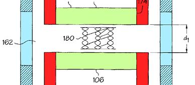
47 Guide Base 21 Circular Frame 20 Movable Pieces Drive Pins Movable Pieces Drive Pins Circular Frame 20 Projection 40 Guide Base 21 Ex. 1103, Figs. 3, 10. The base 21 (blue) has drive pins (22-1 to 22-8) (yellow) that extend through holes (23-1 to 23-8) in the movable pieces (green). Id. at 5:57-6:7. The drive pins (22-1 to 22-8) (yellow) move the pieces (green) along the frame 20 (purple) the distance d when the frame 20 (purple) rotates -39-
48 relative to the base 21 (blue), id., 6:1-8, changing the size of the aperture while maintaining the relative orientation of the movable pieces and the polygonal shape of the aperture, id. at Abstract, 4: Each movable piece has a first straight side facing the aperture, and a second straight side facing the adjacent piece and converging with the first side to form a tip. Each first straight side is parallel to the second straight side of an adjacent die. Id., Fig. 3. As depicted in Figure 8 below, another embodiment of Yasumi comprises six movable pieces (green) disposed within a circular frame 20 (purple). Id. at 7:
49 Projection 40 and Elongate Holes Movable Handle 37 and Circular Frame 20 Guide Groove 39 Movable Pieces Setting Piece 32 Drive Pin 45 Fixed Handle 26 Side Plates 27-1, 27-2 Screw 46 Ex. 1103, Fig 8. The circular frame 20 (purple) and movable pieces (green) are at the end of a movable handle 37 (not shown). Id. at 7: The movable pieces (green) have projections 40 (red) that fit within guide grooves 39 in the frame 20 (purple) that guide the pieces along the frame to open and close the aperture. Id. at 7: The tool includes a fixed handle 26 (gray) comprising a pair of side plates 27-1 and 27-2 with wide end portions. Id. at 7: The frame 20 (purple) and movable pieces (green) sit between the wide end portions of the two side plates 27-1 and 27-2 (gray). Id. -41-
50 A support disk 42 has a larger outer flange 70 that rests against the outside of side plate 27-2 (gray), and a smaller inner portion that passes through the side plate 27-2 (gray) and fits into frame 20 (purple). Ex at 8:1-9. Another support disc 41 rests against the outside of the other side plate, 27-1 (gray). Id. at 8: There is a setting piece 32, between the frame 20 (purple) and side plate 27-1 (gray). Id. at 8: The setting piece 32 and the support discs 41 and 42 have small holes to 36-16, to 36-26, and to (yellow) corresponding to elongated holes 23-1 to 23-6 (also red) in the movable pieces (green). Id. at 8: Drive pins 45 (yellow) are individually inserted into each hole from the outside of the support disc 42. Id. at 8: The pins 45 (yellow) each have a threaded hole. Id. at 8: A screw 46 (also yellow) is screwed into the threaded hole of each pin 45 (yellow) from the outside of the support disc 41. Id. at 8: The fixed handle 26 (gray), the movable handle 37 (purple) and the setting piece 32 are coupled together, and the movable handle 37 (purple) is rotatable relative to the stationary fixed handle 26 (gray). Id. at 8: Initially, when bringing the grip of the movable handle 27 (purple) closer to the fixed handle 26 (gray), the setting piece 32 also turns. Id. at 8: Once a set angle is reached, the setting piece 32 butts against the fixed handle 26 (gray), and further rotational movement of the setting piece 32 is stopped. Id. at 8: Consequently, the -42-
51 pins 45 (yellow) are fixed. Id. Thereafter, bringing the movable handle 27 (purple) closer to the fixed handle 26 (gray) causes the pins 45 (yellow) in the elongated holes 23-1 to 23-6 to move the movable pieces 12 to 17 (green) in the frame 20 (gray), reducing the size of the aperture while maintaining the polygonal shape throughout. Id. at 8: As depicted in Figure 9(a) below, yet another embodiment of Yasumi is directed to an electric wire guide device. Id. at 9: The device comprises two sets of movable pieces 12-1 to 15-1 and 12-2 to 15-2 (green) disposed within guide bases 21-1 and 21-2 (purple). Id. at 9:

52 Side Panels 59-1 and 59-2 Drive Pin 22-1 to 22-4 Drive Pin 22-5 to 22-8 Movable Pieces 12-1 to 15-1 Movable Pieces 12-2 to 15-2 Guide Bases 21-1,
53 Ex. 1103, Figs. 9(a)-(c). The movable pieces 12-1 to 15-1 (green) fit into guide base 21-1 (purple) and movable pieces 12-2 to 15-2 (also green) fit into guide base 21-2 (also purple). Id. at 9: The guide bases (purple) and movable pieces (green) sit between side panels 59-1 and 59-2 (blue). Drive pins 22-1 to 22-4 fit -45-
54 into a recess in the side panel 59-1, through guide base 21-1, and into movable pieces 12-1 to Id. at 9:56-59, 10:68-11:4. Similarly, drive pins 22-5 to 22-8 fit into a recess in the side panel 59-2, through guide base 21-2, and into movable pieces 12-2 to Id. at 9:59-62, 10:68-11:4. The two sets of movable pieces (green) are each arranged to form an aperture. Id. at 9: The aperture formed by movable pieces 12-1 to 15-1 is aligned with the aperture formed by movable pieces 12-2 to Id. at These apertures are in turn aligned with the openings in guide bases 21-1 and 21-2 (purple) and in side panels 59-1 and 59-2 (blue). Id. at 9:39-41, 10:1-6. In operation, the guide bases (purple) are rotated to move the two sets of movable pieces (green) inward and outward to enlarge or reduce the apertures formed by the movable pieces. Id. at 10:7-11:9. Yasumi is in the same field of endeavor as the 560 patent. Ex Like the 560 patent, Yasumi is generally directed to an apparatus that uses coupled movable members disposed about a reference circle to form a variable size aperture, Ex at Abstract, and more specifically to a manual forming and pressing tool, i.e., a crimper, id. at 7: A POSITA would have readily understood that Yasumi is directed to a crimper and that the invention discussed in Yasumi could be used to crimp a stent. Ex
55 Yasumi is also reasonably pertinent to the problem to be solved by the 560 patent. Ex Yasumi recognized a problem with prior art aperture setting devices, namely that it is difficult to change the size of the aperture without introducing a gap between adjacent elements forming the aperture. Ex at 1: This is the same problem the Applicant identified with the AAPA. Ex at Yasumi solves the problem by using an apparatus capable of changing the size of a polygonal aperture while retaining its polygonal shape. Ex at 1:9-12, 1: A POSITA would have understood that the Yasumi device would result in uniform crimping forces to any object within the aperture and remedy the problem identified in the 560 patent. Ex Yasumi is therefore analogous prior art. Id. D. Morales U.S. Patent No. 5,893,852 (Morales) was filed on April 28, 1998, issued on April 13, 1999, and is prior art under at least 102(b). See Ex Morales was not considered by the Examiner during prosecution. Morales discloses [a] stent crimping tool for firmly and uniformly crimping a... stent onto a balloon catheter. Id. at Abstract. -47-
56 Delivery Catheter 11 Stent 10 Balloon 14 Ex. 1104, Fig. 1. Figure 1 of Morales shows an exemplary stent 10 (red) that has been crimped onto a delivery catheter 11 (orange) having an expandable balloon 14 (blue) for expanding the stent 10 within an artery. Id. at Fig. 1, 5: Balloon 14 on Delivery Catheter 11 Stent 10 Teeth
57 Ex. 1104, Fig. 2. Figure 2 shows the stent 10 (red) disposed about a balloon 14 (blue) and held between teeth 30. Id. at Fig. 2, 6:63-7:5. The teeth 30 move radially inward to crimp the stent 10 onto the delivery catheter 11 and expandable balloon 14. Id. at 8: The teeth 30 (green) can crimp stents of various lengths. Id. at 5:5-9. X. STATEMENT OF THE PRECISE RELIEF REQUESTED AND THE REASONS FOR CANCELLATION (37 C.F.R (a) AND (b)) A. Claims 1, 2, 6, 8-10, 14, 15, 18, 23, 25, 27, 28, 31, 33, 37, and 40 Are Invalid As Obvious Over Yasumi In View Of The AAPA 1. Claim 1 Claim 1 of the 560 patent recites: A stent crimper comprising: a plurality of movable dies arranged to form an iris having a longitudinal axis, the iris defining an aperture, the dies disposed about the aperture and between stationary end-walls which are disposed about the longitudinal axis, at least one of the stationary end-walls operatively engaged to the dies at distinct connection locations such that the number of distinct connection locations and the number of dies are the same; each die having a first straight side and a second straight side, the first straight side and the second straight side convering [sic] to form a tip; wherein a portion of the first straight side of each die faces the aperture, each first straight side parallel to the second side of an adjacent die. Ex at 10:
58 Yasumi discloses every limitation of Claim 1, with the possible exception of the preamble. The preamble recites a stent crimper. Yasumi is considered a stent crimper for purposes of analyzing validity of the challenged claims. It is well established that a recitation of the intended use of a claimed invention must result in a structural difference between the claimed invention and the prior art in order to patentably distinguish the claimed invention from the prior art. In re Casey, 370 F.2d 576, 580 (C.C.P.A. 1967). If the prior art structure is capable of performing the intended use, then it meets the claim. Id. The recitation in the preamble of the challenged claim to a stent crimper is not in the nature of a structural limitation; it merely expresses what the device is desired to do. The devices disclosed in Yasumi are capable of crimping a stent. The recitation of a stent crimper, therefore, does not patentably distinguish the claimed inventions from Yasumi. Indeed, the Examiner relied on this same rationale for concluding during prosecution that Whitesell (pliers), Tuberman (tube pointer), and Wilhelm (crimping tool) were stent crimpers because each was capable of crimping a stent. Ex at 45-46, 72. The Applicant did not dispute the Examiner s position. Id. at 34-36, Yasumi is no different from the tools disclosed in Whitesell, Tuberman, and Wilhelm in terms of its suitability to crimp a stent. Therefore, Yasumi alone is a stent crimper for the same reasons the Examiner found -50-
59 Whitesell, Tuberman, and Wilhelm to be stent crimpers. Moreover, as noted above, the preamble does not limit the claims. The AAPA also discloses the preamble stent crimper. A detailed analysis of Claim 1 is provided in the following claim chart. See also Ex ASSERTED CLAIMS [1 preamble] A stent crimper comprising: [1a] a plurality of movable dies arranged to form an iris having a longitudinal axis, the iris defining an aperture, PRIOR ART Yasumi discloses: a manual forming and pressing tool. (Ex at 7:33-38; id. at 1:35-39, 9:30-34, 11:25-30.) This tool is capable of crimping a stent. Therefore, Yasumi is a stent crimper. Moreover, the preamble stent crimper does not limit the claim. The AAPA discloses: [a] cam actuated stent crimper. (Ex at 1:62.) Yasumi discloses a plurality of movable dies (movable pieces or 12-19) arranged to form an iris having a longitudinal axis, the iris defining an aperture: [A]t least three or more substantially triangular movable pieces are sequentially arranged in the form of a ring, an aperture is formed by one end portion of an inner side of each movable piece. (Ex at Abstract; id. at 1:47-50, 2:45-47, 2:65-3:3, 4:42-44, 8:53-54, 9:63-67.) -51-


 Iris")

60 ASSERTED CLAIMS PRIOR ART Iris Defining an Aperture Longitudinal Axis 0 Plurality Of Movable Dies (12-19) Plurality of Movable Dies (12-17) Iris Defining Aperture Longitudinal Axis of Iris & Aperture -52-
61 ASSERTED CLAIMS [1b] the dies disposed about the aperture and between stationary end-walls which are disposed about the longitudinal axis, PRIOR ART (Ex. 1103, Figs. 3 & 8 (excerpt). 5 ) Yasumi discloses an embodiment with dies (movable pieces or 12-19) disposed about the aperture and between stationary end-walls (wide end portions of the fixed handle side plates 27-1 and 27-2) which are disposed about the longitudinal axis: A fixed handle 26 is composed of a pair of parallel spatular side plates 27-1 and [T]he plurality of movable pieces 12 to 17 is interposed between the wide end portions of the two side plates 27-1 and 27-2 of the fixed handle 26. (Ex at 7:39-8:9.) Next, the movable handle 37 is turned to reduce the angle between it and the fixed handle 26, butting the setting piece 32 against the adjust cam 31 to stop the rotational movement of the setting piece 32. By further rotating the movable cam 37 towards the fixed handle 26,.... (Id. at 9:26-34; id. at 8:42-54, 9:3-15. A POSITA would have understood based on the Yasumi disclosure that the fixed handle 26 is stationary. (Ex ) 5 Note that figures from the prior art have been annotated in the tables throughout the Petition with red boxes to identify pertinent elements and callouts to label important features. -53-
62 ASSERTED CLAIMS PRIOR ART Dies Disposed About Aperture And Between Stationary End-Walls Longitudinal Axis Stationary End- Wall (wide end portion of 27-2) Disposed About the Longitudinal Stationary End-Wall (wide end portion of 27-1) Disposed About the Longitudinal Axis (Ex. 1103, Fig. 8.) Yasumi includes an additional embodiment that discloses dies (movable pieces 12-1 to 15-1 and 12-2 to 12-5) disposed about the aperture and between stationary endwalls (left- and right-hand side panels 59-1 and 59-2) which are disposed about the longitudinal axis: At this time, since the frames 20-1 and 20-2 are fixed to the side panels 59-1 and 59-2, as referred to previously, and do not move,.... (Ex at 10:42-49; also id. at 9:37-10:2.) -54-
63 ASSERTED CLAIMS PRIOR ART Stationary End-Wall (Side Panel 59-1) Disposed About the Longitudinal Axis Stationary End-Wall (Side Panel 59-2) Disposed About the Longitudinal Axis Dies 12-1 to 15-1 and 12-2 to 15-2 Disposed About Aperture And Between Stationary End-Walls Longitudinal Axis [1c] at least one of the stationary end-walls operatively engaged to the dies at distinct connection locations such that the number of distinct connection locations and the number of dies are the same; (Ex. 1103, Fig. 9(a).) Yasumi discloses at least one of the stationary end-walls (wide end portions of the fixed handle side plates 27-1 and 27-2) operatively engaged to the dies (movable pieces or 12-19) at distinct connection locations (elongated holes 23-1 to 23-6) such that the number of distinct connection locations and the number of dies are the same: In Figure 8, each movable piece has one elongated hole that engages the piece to the wide-end portions of the fixed handle side plates 27-1 and 27-2 via support disks 42 & 43, drive pins 45, screws 46, and setting piece 32. The six elongated holes are the six distinct connection locations that operatively engage the six dies to the stationary end- -55-
 Six Dies (12-17) with Six Distinct Connection Locations (23-1 to 23-6) Stationary End-Walls (wide end portions of 27-1 & 27-1) Operatively Engaged To The Dies (Ex. 1103, Fig. 8.")
64 ASSERTED CLAIMS PRIOR ART walls. (See Ex at 8:1-54.) Six Dies (12-17) with Six Distinct Connection Locations (23-1 to 23-6) Stationary End-Walls (wide end portions of 27-1 & 27-1) Operatively Engaged To The Dies (Ex. 1103, Fig. 8.) Yasumi also discloses at least one of the stationary endwalls (left- and right-hand side panels 59-1 and 59-2) operatively engaged to the dies (movable pieces 12-1 to 15-1 and 12-2 and 15-2) at distinct connection locations (elongated holes 23-1 to 23-8) such that the number of distinct connection locations and the number of dies are the same: -56-
65 ASSERTED CLAIMS PRIOR ART In Figure 9(a), each movable piece has one elongated hole (23-1 to 23-8) that engages the die to the side panels 59-1 and 59-2 that are the stationary end-walls. Drive pins 22-1 to 22-8 extend through the elongated holes on each die to fit into ring-shaped grooves 83 and 84 that are formed in the side panels 59-1 and The eight elongated holes are the eight distinct connection locations that operatively engage the eight dies to the stationary end-walls. (See Ex at 9:56-62, 10:68-11:4.) Stationary End-Wall (Side Panel 59-1, blue) Operatively Engaged to the Dies Stationary End-Wall (Side Panel 59-2, blue) Operatively Engaged to the Dies Eight Dies (12-1 to 15-1, 12-2 to 15-2) with Eight Distinct Connection Locations ( ) (Ex. 1103, Fig. 9(a).) [1d] each die having a first straight side and Yasumi discloses each die (movable pieces or 12-19) having a first straight side (inner side) and a second straight side, the first straight side and the second straight side converging to form a tip; wherein a portion of the first -57-
66 ASSERTED CLAIMS a second straight side, the first straight side and the second straight side convering [sic] to form a tip; wherein a portion of the first straight side of each die faces the aperture, each first straight side parallel to the second side of an adjacent die. PRIOR ART straight side of each die faces the aperture, each first straight side parallel to the second side of an adjacent die: [A]n aperture is formed by one end portion of an inner side of each movable piece and the movable piece... (Ex at Abstract; see id. at Claim 1, 2:48-59; 4:42-44) Second Straight Side (Blue) Of Die 19 Converging With First Side (Red) To Form Tip First Straight Side (Red) of Die 19 Facing Aperture First Straight Side (Red) of Die 16 Parallel To Second Straight Side (Blue) of Adjacent Die 17 (Ex. 1103, Fig. 3.) 2. Claim 10 Independent Claim 10 recites limitations substantially similar to those in Claim 1, but adds limitations directed to (1) an aperture having a substantially regular polygonal shape; (2) dies having an inward facing straight side which -58-
67 faces the longitudinal axis of the aperture both when the dies move to maximize the aperture and when the dies move to minimize the aperture; (3) the longitudinal axis [of the aperture] passing through a point substantially centered on the end-walls; and (4) a rotatable actuation device coupled to the dies, rotation of the actuation device causing the inward facing straight sides of the dies to move inward and reduce the size of the aperture or outward so as to increase the size of the aperture. Yasumi discloses these limitations. A detailed analysis of Claim 10 is provided in the following claim chart. See also Ex ASSERTED CLAIMS [10 Preamble] A stent crimper comprising: [10a] a plurality of movable dies arranged to form an iris, [10b] the dies disposed about an aperture, PRIOR ART See Claim [1 Preamble]. See Claim [1a]. See Claim [1b]. -59-
![ASSERTED CLAIMS [10c] the aperture having a longitudinal axis and a substantially regular polygonal shape, PRIOR ART Yasumi discloses the aperture having a longitudinal axis. See Claim [1a].](/docs-images/88/116188015/images/68-1.jpg "6 Yasumi discloses an aperture having a substantially regular polygonal shape.")
68 ASSERTED CLAIMS [10c] the aperture having a longitudinal axis and a substantially regular polygonal shape, PRIOR ART Yasumi discloses the aperture having a longitudinal axis. See Claim [1a]. 6 Yasumi discloses an aperture having a substantially regular polygonal shape. [I]t will easily be understood that the structure of this embodiment can generally be applied to regular polygonal apertures. (Ex at 4:62-64; see id. at 4:38-41, 6:14-15.) [10d] See Claim [1d]. 7 Aperture 11 with Substantially Regular Polygonal Shape (Ex. 1103, Fig. 3; see id. at Figs. 2, 5(a), 7(a).) 6 Claim [10c] recites the aperture having a longitudinal axis and Claim [1a] recites an iris having a longitudinal axis. Because the iris defines the aperture, disclosure in Yasumi of an iris having a longitudinal axis also discloses an aperture having a longitudinal axis -60-
69 ASSERTED CLAIMS each of the dies having an inward facing straight side which faces the longitudinal axis of the aperture, [10e] both when the dies move to maximize the aperture and when the dies move to minimize the aperture, PRIOR ART Yasumi discloses each of the dies (movable pieces or 12-19) having an inward facing straight side which faces the longitudinal axis of the aperture both when the dies move to maximize the aperture and when the dies move to minimize the aperture: Movable Pieces Face Axis 7 Claim [10d] recites an inward facing straight side which faces the longitudinal axis of the aperture and Claim [1d] recites a portion of the first straight side of each die faces the aperture. Because the longitudinal axis of the aperture is located central to the aperture, disclosure in Yasumi of the first straight side of each die facing the aperture also discloses an inward facing straight side which faces the longitudinal axis of the aperture. -61-
 Yasumi teaches that the polygonal shape of the aperture is maintained as the dies (movable pieces 12-17 or 12-19) move in or out.")
![[T]he size of a predetermined polygonal aperture can be changed, retaining the polygonal configuration. (Ex. 1103 at 1:11-13; see id. at Abstract, 1:40-43, Claim 1.](/docs-images/88/116188015/images/70-2.jpg ") Maintaining the polygonal shape results in the first straight side facing the longitudinal axis of the aperture while moving in or out. [10f] the dies between two stationary end- See Claim [1b].")
70 ASSERTED CLAIMS PRIOR ART Movable Pieces Face Axis Longitudinal Axis (Ex. 1103, Fig. 8.) Yasumi teaches that the polygonal shape of the aperture is maintained as the dies (movable pieces or 12-19) move in or out. [T]he size of a predetermined polygonal aperture can be changed, retaining the polygonal configuration. (Ex at 1:11-13; see id. at Abstract, 1:40-43, Claim 1.) Maintaining the polygonal shape results in the first straight side facing the longitudinal axis of the aperture while moving in or out. [10f] the dies between two stationary end- See Claim [1b]. 8 8 Claim [10f] recites two stationary end-walls while Claim [1b] recites stationary end-walls, plural. Because two stationary end-walls is a subset of stationary endwalls, disclosure in the AAPA of stationary end-walls also discloses two stationary end-walls. -62-
71 ASSERTED CLAIMS walls disposed about the longitudinal axis, [10g] the longitudinal axis passing through a point substantially centered on the end-walls, PRIOR ART Yasumi discloses the longitudinal axis passing through a point substantially centered on the end-walls (wide end portions of the fixed handle side plates 27-1 and 27-2): The frame 20 having thus mounted therein the plurality of movable pieces 12 to 17 is interposed between the wide end portions of the two side plates 27-1 and 27-2 of the fixed handle 26,... The frame 20 has formed therein on the side of the side plate 27-2 a circular recess coaxial with the frame 20,..., and the support disc 42 is fitted into this circular recess.... The circular projection 33-1 is fitted into the circular hole 28-1 of the side plate (Ex at 7:57-8:21.) -63-

, a pin 51 of a connector and an electric wire 53 are inserted into the aperture setting device through openings 54 and 55 formed in left-and right-hand side panel 59-1 and 59-2.")
72 ASSERTED CLAIMS PRIOR ART Stationary End-Wall (Wide End Portion of Side Plate 27-2) Stationary End-Wall (Wide End Portion of Side Plate 27-1) Longitudinal Axis Passing Through A Point Substantially Centered On The Stationary End-Walls (Ex. 1103, Fig. 8.) Yasumi includes an additional embodiment that discloses the longitudinal axis passing through a point substantially centered on the end-walls (left- and right-hand side panels 59-1 and 59-2): As shown in FIG. 9(a), a pin 51 of a connector and an electric wire 53 are inserted into the aperture setting device through openings 54 and 55 formed in left-and right-hand side panel 59-1 and The axes of the aperture setting portions 81 and 82 lie on the same straight line, which is substantially in alignment with the centers of the openings 54 and 55 of the side panels of the casing. (Id. at 9:37-10:2.) -64-
73 ASSERTED CLAIMS PRIOR ART Stationary End-Wall (Side Panel 59-1) Stationary End-Wall (Side Panel 59-2) Longitudinal Axis Passing Through A Point Substantially Centered On The Stationary End-Walls (Ex. 1103, Fig. 9(a); see id. at FIG. 9(b)-(c), 9:35-10:11.) [10h] a rotatable actuation device coupled to the dies, Yasumi discloses a rotatable actuation device (circular frame 20) coupled to the dies (movable pieces or 12-19): [T]he movable pieces 12 to 19 are disposed in a circular frame As drive means, a guide base 21 is provided,... Turning the guide base 21 about the axis 0 clockwise in FIG. 3 relative to the frame 20, the drive pins 22-1 to 22-8 move on the same circle about the axis 0 relative to the frame 20. The drive pins 22-1 to 22-8 drive the movable pieces 12 to 19 through the elongated holes 23-1 to 23-8, respectively, by which the movable pieces are moved along their bases to approach the axis 0. (Ex at 5:39-6:8.) The frame 20 having thus mounted therein the plurality of -65-
74 ASSERTED CLAIMS PRIOR ART movable pieces 12 to 17 is interposed between the wide end portions of the two side plates 27-1 and 27-2 of the fixed handle 26,... The movable handle 37 and the fixed handle 26 are designed so that they can turn about the axis of the frame 20 relative to each other, and the movable pieces 12 to 17 are moved by the relative rotational movement of the handles 37 and 26. (Id. at 7:57-68.) Rotatable Actuation Device 20 Dies Coupled to Rotatable Actuation Device 20 by Projections 40 and Guide Groves 39 (Ex. 1103, Fig. 8) [10i] rotation of the actuation device causing the inward facing straight sides of the dies to move inward and reduce the size of the aperture or outward so as to increase the size of Yasumi discloses rotation of the actuation device (circular frame 20) causing the inward facing straight sides of the dies (movable pieces or 12-19) to move inward and reduce the size of the aperture or outward so as to increase the size of the aperture: Bringing the grips of the handles 26 and 37 closer to each other, the pins 45 move in the elongated holes 23-1 to 23-6 to move the movable pieces 12 to 17 in the frame 20, reducing the aperture defined by the movable pieces 12 to 17. (Ex at 8:42-54; see id. at 5:39-6:8, 7:57-68.) -66-
75 ASSERTED CLAIMS the aperture. PRIOR ART 3. Claim 18 Independent Claim 18 recites limitations substantially similar to those previously recited in Claims 1 and 10. See Part X.A.1 and.2. 9 Claim 18 also adds the limitation eight or more movable dies. Yasumi discloses this limitation. A detailed analysis of Claim 18 is provided in the following claim chart. See also Ex ASSERTED CLAIMS [18 Preamble] See Claim [1 Preamble]. PRIOR ART A stent crimper comprising: [18a] eight or more movable dies arranged to form an iris, Yasumi discloses movable dies arranged to form an iris. See Claim [1a]. Yasumi also discloses eight or more movable dies: FIG. 3 and FIG. 10 embody the principles of the aperture setting device of the present invention and depict the state in which movable pieces 12, 13, 14, around the axis 0 9 Claim 18 recites an inward facing flat portion and Claim 1 recites a first straight side of each die fac[ing] the aperture. The disclosure in Yasumi of a first straight side facing the aperture equally supports disclosure of an inward facing flat portion. -67-
76 ASSERTED CLAIMS PRIOR ART have respectively been moved along their bases by the aforesaid maximum distance d. (Ex at 5:39-6:13.) Eight Movable Dies Iris (Ex. 1103, Fig. 3; see id., Fig. 2.) [18b] the iris defining an aperture of a substantially regular polygonal shape, [18c] See Claims [1a] (iris defining aperture), [10c] (aperture having substantially regular polygonal shape). See Claim [1a], [10c]. the aperture having a longitudinal axis, [18d] See Claim [1d], [10d]. each die having an inward facing flat portion which faces the longitudinal axis of the aperture -68-
77 ASSERTED CLAIMS PRIOR ART [18e] See Claim [10e]. both when the dies move to maximize the aperture and when the dies move to minimize the aperture, [18f] the dies between stationary end walls and operatively engaged to at least one of the stationary endwalls, [18g] See Claims [1b] (dies between stationary end-walls) and [1c] (at least one stationary end-wall operatively engaged to the dies). See Claim [1b]. the stationary end-walls disposed about the longitudinal axis, [18h] the iris comprising at least eight of the inward facing flat portions, See Claim [1a] & [1d] (movable dies arranged to form an iris and a portion of the first straight side of each die faces aperture), Claim [18a] (eight dies). -69-
78 [18i] ASSERTED CLAIMS the aperture being reducible in size by moving the inward facing flat portions toward the longitudinal axis of the aperture, [18j] PRIOR ART See Claims [10d] (inward facing straight side which faces the longitudinal axis), [10i] (inward facing straight sides of the dies to move inward and reduce the size of the aperture). See Claim [10h]. a rotatable actuation device coupled to the dies, [18k] See Claim [10i]. rotation of the actuation device causing the inward facing straight sides of the dies to move inward and reduce the size of the aperture or outward so as to increase the size of the aperture. -70-
79 4. Claim 27 Independent Claim 27 recites limitations substantially similar to those previously recited in Claims 1 and 10. See Part X.A.1 and Claim 27 also adds the limitation the blades coupled to one another so as to be movable inward or outward simultaneously. Yasumi discloses this limitation. A detailed analysis of Claim 27 is provided in the following claim chart. See also Ex ASSERTED CLAIMS [27 Preamble] A stent crimper comprising: [27a] an aperture with a plurality of movable blades disposed thereabout, [27b] the aperture having a longitudinal axis and being substantially polygonal, PRIOR ART See Claim [1 Preamble]. See Claim [1b]. See Claim [10c]. 10 Claim 27 differs from the previous claims because it recites blades instead of dies. But those terms are used interchangeably. See Part VIII.B. -71-
80 ASSERTED CLAIMS [27c] the blades between stationary endwalls substantially centered about the longitudinal axis, [27d] the blades coupled to one another so as to be movable inward or outward simultaneously, PRIOR ART See Claims [1b] (dies between stationary end-walls), [10g] (longitudinal axis passing through a point substantially centered on the end-walls). Yasumi discloses the blades (movable pieces or 12-19) coupled to one another so as to be movable inward or outward simultaneously: Each blade is connected via numerous components such that when one blade moves, they all move together simultaneously. For example, the blades are coupled via the rotatable actuation device. The blades are also coupled via the drive pins and screws. A center aligning device comprising:... a first drive member disposed opposite one side of the faces of said first movable pieces and having first drive pins thereon,... for simultaneously moving said first movable pieces relative to said first frame to set the size of said first polygonal aperture. (Ex at Claim 1; see id. at 2:47-59, 4:12-17, 5:48-51, 7:48-57.) -72-
81 ASSERTED CLAIMS PRIOR ART Rotatable Actuation Device 20 Dies Coupled via Drive Pins 45, Screws 46, and Actuation Device 20 (Ex. 1103, Fig. 8.) [27e] movement of the blades outward increasing the size of the aperture, [27f] movement of the blades inward decreasing the size of the aperture, See Claim [10i]. See Claim [10i]. -73-
82 ASSERTED CLAIMS [27g] the aperture remaining substantially regular polygonal when it is sized to receive a stent therein and when the blades minimize the aperture. PRIOR ART See Claims [10c] (substantially regular polygonal shape), [10e] (when the dies move to maximize the aperture and when the dies move to minimize the aperture) Claim 37 Independent Claim 37 recites limitations substantially similar to those previously recited in Claims 1 and 10, see Part IX.A.1 and.2, but adds the limitation overlapping movable dies. Yasumi discloses this limitation. A detailed analysis of Claim 37 is provided in the following claim chart. See also Ex ASSERTED CLAIMS [37 Preamble] A stent crimper See Claim [1 Preamble]. PRIOR ART 11 Claim [27g] recites when [the aperture] is sized to receive a stent therein and Claim [10e] recites when the dies move to maximize the aperture. The disclosure in Yasumi supporting Claim [10e] equally supports Claim [27g] because the aperture is maximized when it is sized to receive a stent. -74-
83 ASSERTED CLAIMS comprising: [37a] a plurality of overlapping movable dies arranged to form an iris, PRIOR ART Yasumi discloses a plurality of movable dies arranged to form an iris. See Claim [1a]. Yasumi discloses a plurality of overlapping movable dies (movable pieces or 12-19): Referring first to FIG. 1,... the movable piece 13 is disposed with one side 13a of its triangle held partly in agreement with one side 12a of the movable piece 12 forming one side of the pentagonal aperture area 11 but with one end of the piece 13 displaced outwardly relative to the area The other movable pieces are also likewise disposed one after another. (Ex at 2:44-59.) Dies (12-19) Overlapping (Ex. 1103, Fig. 3; id. at Figs. 1-2.) -75-
84 ASSERTED CLAIMS PRIOR ART [37b] the dies disposed about an aperture, the aperture having a longitudinal axis, [37c] the dies between stationary endwalls disposed about the longitudinal axis, [37d] the dies operatively engaged to at least one of the stationary endwalls; [37e] each die having a first straight side and a second straight side, the first straight side and the second straight side converging to form a tip; wherein a portion of the first straight side of See Claims [1b], [10c]. See Claim [1b]. See Claim [1c] (at least one of the stationary end-walls operatively engaged to the dies). See Claim [1d]. -76-
85 ASSERTED CLAIMS each die faces the aperture, each first straight side parallel to the second side of an adjacent die. PRIOR ART 6. Claim 40 Independent Claim 40 recites limitations substantially similar to those previously recited in Claims 1 and 10. See Part IX.A.1 and A detailed analysis of Claim 40 is provided in the following claim chart. See also Ex ASSERTED CLAIMS [40 Preamble] A stent crimper comprising: [40a] a plurality of movable dies arranged to form an iris disposed about an aperture, See Claim [1 Preamble]. PRIOR ART See Claims [1a] (plurality of movable dies arranged to form an iris), [1b] (dies disposed about the aperture). 12 Claim 40 recites stationary plates while Claim 1 recites stationary end-walls. However, as discussed above in Part VIII.C, the stationary plates of Claim 40 and the stationary end-walls of Claim 1 are interchangeable. -77-
86 ASSERTED CLAIMS PRIOR ART [40b] the aperture having a longitudinal axis, [40c] the plurality of movable dies between stationary plates disposed about the longitudinal axis, [40d] each die in communication with an actuation device, [40e] the actuation device constructed and arranged such that rotational See Claim [10c]. See Claim [1b]. See Claim [10h]. 13 See Claim [10i] Claim 10 uses coupled to and Claim 40 uses in communication with. The disclosure in Yasumi for a rotatable actuation device coupled to the dies also supports each die in communication with an actuation device. 14 Claim [10i] recites rotation of the actuation device [reducing] the size of the aperture or [increasing] the size of the aperture and Claim [40e] recites rotational motion of the actuation device opens or closes the aperture. The disclosure in Yasumi showing Claim [10i] applies equally to Claim [40e]. -78-
87 ASSERTED CLAIMS motion of the actuation device opens or closes the aperture, PRIOR ART [40f] the dies operatively engaged to at least one of the stationary plates; [40g] each die having a first straight side and a second straight side, the first straight side and the second straight side convering to form a tip; wherein a portion of the first straight side of each die faces the aperture, each first straight side parallel to the second side of an adjacent die. See Claim [1c]. See Claim [1d]. 7. Claims 2 and 28 Dependent Claims 2 and 28 add a limitation substantially similar to Claim [10h-i]: a rotatable actuation device coupled to the [dies/blades], rotation of the -79-
88 actuation device causing the [dies/blades] to move inward [and reduce the size of the aperture] or outward [so as to increase the size of the aperture.] 15 Accordingly, Yasumi discloses every limitation of Claims 2 and 28. See Part X.A.2; Ex Claims 6 and 15 Dependent Claims 6 and 15 share an identical limitation substantially similar to Claim 18[a]: wherein at least 8 dies are provided. Accordingly, Yasumi discloses every limitation of Claims 6 and 15. See Part X.A.3; Ex Claims 8, 25, and 33 Dependent Claims 8, 25, and 33 share an identical limitation of wherein the dies are moved cooperatively inward during the moving step, which is disclosed by Yasumi. The dies in Yasumi (movable pieces or 12-19) are all configured to move cooperatively inward during the moving step because each one is linked to the same rotatable actuation device and the stationary end-walls such that the dies all move simultaneously. Ex at Claim 1; see also id. at Abstract, 2:47-59, 5:48-51, 4:12-17, 7:48-57, 8:50-54; Ex Claim 28 differs from Claims 2 and 10 because it recites blades instead of dies, but blades and dies are used interchangeably. See Part VIII.B. -80-
89 10. Claims 9, 14, 23, and 31 Dependent Claims 9, 14, 23, and 31 share an identical limitation of wherein the dies are wedge-shaped, which is disclosed by Yasumi. Wedge-Shaped Dies Ex. 1103, Fig. 8; id. at Abstract ( substantially triangular movable pieces ), 1:48-49, 6:31-37; Ex Reason, Basis, or Motivation to Combine A patent claim is unpatentable if the differences between the subject matter sought to be patented and the prior art are such that the subject matter as a whole would have been obvious to a POSITA. 35 U.S.C It is not necessary that the prior art be physically combinable to render a claim obvious under 103. Allied Erecting & Dismantling Co. v. Genesis Attachments, LLC, 825 F.3d 1373, 1381 (Fed. Cir. 2016). The test is whether a skilled artisan would have been motivated to combine the teachings of the prior art references to achieve the claimed invention. Id. -81-
90 As noted previously, the press tool of Yasumi is capable of crimping a stent and, thus, it is a stent crimper. Moreover, to the extent necessary, it would have been obvious to a POSITA to modify Yasumi for use as a stent crimper in view of the AAPA. Ex Yasumi recognized that prior art aperture setting devices suffered from problems when there were gaps between adjacent dies such that the article in the aperture could end up wedged between the dies. Ex at 1: Yasumi set out to solve this problem by using dies arranged to form a polygonal aperture. Id. at 1: Yasumi did not limit the applications for the disclosed polygonal aperture setting device. As explained in Yasumi: In the past, there has not been put to practical use a device which is capable of changing with a simple arrangement, a polygonal aperture into various sizes continuously or stepwise, retaining it on the same axis. Such a device, if realized, would be of great ability when employed in such devices as a chuck, a press tool, an electric wire guide device, a drawing die, a control valve and so forth. Id. at 1: In particular, one of the embodiments disclosed in Yasumi is directed to a manual forming and pressing tool. Id. at 7:33-38, 9:30-34, 11: A POSITA would have understood that a manual forming and pressing tool is just another term used to refer to a crimper. Ex A POSITA would have been motivated by the disclosure in Yasumi to look for applications for the disclosed tool, and in particular would have been motivated to look for suitable crimping applications. Id. -82-
91 It would have been well known to a POSITA prior to September 22, 1999 that stent crimping is one field of crimping applications and that stents must be crimped uniformly. See Ex (citing Ex at 1:35-48 ( One shortcoming of this conventional mounting and securing means is that it often produces irregular distortion of the stent.... Another shortcoming is that it may weaken a portion or portions of the stent.... ); Ex at 1:59-2:2 ( Nonuniform stent crimping can result in sharp edges being formed along the now uneven surface of the crimped stent. Furthermore, non-uniform stent crimping may not achieve the desired minimal profile for the stent and catheter assembly. ); Ex at 1:49-2:14 ( Moreover, non-uniformity of the crimping may be experienced[.] ); Ex at 1:66-2:18 ( [T]he stent may be non-uniformly crimped onto the delivery device which can cause problems during advancement of the stent to the desired location within a body lumen and/or during deployment of the stent. ); Ex at 2:2-5 ( In the past this crimping was often done by hand, which does not provide optimum results due to the uneven force being applied. )). A POSITA would have recognized that many prior art stent crimpers suffered from a well-known uneven crimping problem. Ex For example, a POSITA would have known that the AAPA dies form elongate portions that poke radially inward to crimp a stent, resulting in uneven forces that can damage the stent. Ex at 65; Ex A POSITA would have had a -83-
92 reason, basis, or motivation to improve upon the AAPA, and other prior art stent crimpers, by using Yasumi as a stent crimper, thereby solving the uneven crimping forces problem. Ex A POSITA would have known that using the straight-sided die/polygonal aperture disclosed in Yasumi for crimping a stent would address the well-known problem of uneven crimping forces. Ex The problem of uneven crimping forces exists in many crimping applications, such as crimpers for pointing tubes and crimping electrical connections. Id In particular, crimpers that, like the AAPA, use elongated dies equally spaced around an aperture that move radially inward to crimp a device have long been known to apply uneven crimping forces. Id. 159 (citing Exs. 1114, 1118, 1119, 1121, 1125). This problem has been solved in many instances by using a straight-sided die/polygonal aperture, such as the one disclosed in Yasumi. For example, Whitesell recognized that asymmetric crimping detrimentally concentrated crimping force along the plane where the dies converged, compromising both electrical reliability and mechanical strength. Ex at 1: Whitesell improved on prior art devices by providing radially opposed jaws [or dies] that direct and balance compressive forces toward the center of the work. Id. at Abstract. -84-
93 Baker disparaged a number of prior art tube pointing apparatus that used dies which reciprocate radially inward because they resulted in the metal tube extruding into openings between the dies. Ex at 1:13-20, 1:33-37 (discussing Exs. 1122, 1123, 1124). Baker solved the problem by using dies that were arranged to form a polygonal aperture with no gaps in between. Id. at 1:45-48, 1: A POSITA would have had a reason, basis or motivation to solve the problem in the stent crimping field in the same manner. Ex A POSITA therefore would have had a reason, basis or motivation to use Yasumi as a stent crimper to provide the even crimping forces necessary to safely and effectively crimp a stent. Id B. Ground 2: Claims 11, 17, 19, 26, 34, 35, and 39 Are Obvious Over Yasumi In View Of the AAPA and Morales 1. Claim 39 Independent Claim 39 recites limitations substantially similar to those previously recited in Claim 1, but adds limitations directed to an aperture having a center and a first opening and a second opening, and the dies constructed and arranged to have a length exceeding the length of a stent with a longitudinal axis passing through both the first opening and the second opening. These limitations are disclosed in or obvious over Yasumi either alone or in view of the AAPA. As explained above, Yasumi is considered a stent crimper for -85-
94 purposes of analyzing validity of the challenged claims. The AAPA is also a stent crimper. Therefore, Yasumi and the AAPA would have been constructed to accommodate a balloon catheter and stent within the crimping aperture. Ex An aperture having a center and openings on both ends, i.e., a first opening and a second opening, is necessary to permit the distal and proximal portions of the balloon catheter to extend outside the crimping aperture while accommodating the stent and balloon portion of the catheter within the aperture. Id. Moreover, a POSITA would have known the desirability of crimping the stent evenly and, thus, it would have been obvious to make the length of the dies exceed the length of the stent to ensure that the entire stent fit easily within the aperture, provide a margin of error so that no portion of the stent would be missed during the crimping procedure, and to account for manufacturing tolerances. Ex To the extent these limitations are not viewed as disclosed in or obvious in view of Yasumi or the AAPA, Morales also discloses these limitations. Ex A detailed analysis of Claim 39 is provided in the following claim chart. See also id ASSERTED CLAIMS [39 Preamble] A stent crimper See Claim [1 Preamble]. PRIOR ART -86-
![ASSERTED CLAIMS comprising: [39a] a plurality of movable dies arranged to form an iris disposed about an aperture, [39b] the aperture having a center and a first opening and a second opening, PRIOR](/docs-images/88/116188015/images/95-1.jpg "ART See Claims [1a] (plurality of movable dies arranged to form an iris), [1b] (dies disposed about the aperture).")
95 ASSERTED CLAIMS comprising: [39a] a plurality of movable dies arranged to form an iris disposed about an aperture, [39b] the aperture having a center and a first opening and a second opening, PRIOR ART See Claims [1a] (plurality of movable dies arranged to form an iris), [1b] (dies disposed about the aperture). Yasumi discloses an aperture (between movable pieces or between movable pieces 12-1 to 15-1 and 12-2 to 12-5) having a center and a first opening and a second opening. Bringing the grips of the handles 26 and 37 closer to each other, the pins 45 move in the elongated holes 23-1 to 23-6 to move the movable pieces 12 to 17 in the frame 20, reducing the aperture defined by the movable pieces 12 to 17. (Ex at 8:50-54; id. at 9:30-34.) Second Opening (Behind Dies) First Opening (In Front Of Dies) Dies 12 to 17 Center of Aperture (Id. at Fig. 8.) -87-
UNITED STATES PATENT AND TRADEMARK OFFICE BEFORE THE PATENT TRIAL AND APPEAL BOARD. BLACKHAWK SPECIALITY TOOLS, LLC Petitioner
 UNITED STATES PATENT AND TRADEMARK OFFICE BEFORE THE PATENT TRIAL AND APPEAL BOARD BLACKHAWK SPECIALITY TOOLS, LLC Petitioner v. WEATHERFORD INTERNATIONAL, LLC. Patent Owner Patent 5,575,333 PETITION FOR
UNITED STATES PATENT AND TRADEMARK OFFICE BEFORE THE PATENT TRIAL AND APPEAL BOARD. MILWAUKEE ELECTRIC TOOL CORPORATION Petitioner
 UNITED STATES PATENT AND TRADEMARK OFFICE BEFORE THE PATENT TRIAL AND APPEAL BOARD MILWAUKEE ELECTRIC TOOL CORPORATION Petitioner v. IRWIN INDUSTRIAL TOOL COMPANY Patent Owner Patent No. 8,579,555 Issued:
Paper Entered: 2 February 2017 UNITED STATES PATENT AND TRADEMARK OFFICE BEFORE THE PATENT TRIAL AND APPEAL BOARD
 Trials@uspto.gov Paper 8 571-272-7822 Entered: 2 February 2017 UNITED STATES PATENT AND TRADEMARK OFFICE BEFORE THE PATENT TRIAL AND APPEAL BOARD WANGS ALLIANCE CORPORATION d/b/a WAC LIGHTING CO., Petitioner,
UNITED STATES PATENT AND TRADEMARK OFFICE BEFORE THE PATENT TRIAL AND APPEAL BOARD. MILWAUKEE ELECTRIC TOOL CORPORATION Petitioner
 UNITED STATES PATENT AND TRADEMARK OFFICE BEFORE THE PATENT TRIAL AND APPEAL BOARD MILWAUKEE ELECTRIC TOOL CORPORATION Petitioner v. IRWIN INDUSTRIAL TOOL COMPANY Patent Owner Patent No. 8,579,554 Issued:
UNITED STATES PATENT AND TRADEMARK OFFICE BEFORE THE PATENT TRIAL AND APPEAL BOARD. BUNGIE, INC., Petitioner, WORLDS INC., Patent Owner.
 Filed on behalf of: Bungie, Inc. By: Michael T. Rosato Matthew A. Argenti WILSON SONSINI GOODRICH & ROSATI 701 Fifth Avenue, Suite 5100 Seattle, WA 98104-7036 Tel.: 206-883-2529 Fax: 206-883-2699 Email:
IN THE UNITED STATES PATENT AND TRADEMARK OFFICE. U.S. Pat. No. 5,544,417
 IN THE UNITED STATES PATENT AND TRADEMARK OFFICE In re Inter Partes Review of: U.S. Pat. No. 5,544,417 Filed: October 20, 1994 Inventor: Atos, et al. Issued: August 13, 1996 Petition Filing Date: August
Date: August 27, 2013 UNITED STATES PATENT AND TRADEMARK OFFICE BEFORE THE PATENT TRIAL AND APPEAL BOARD. ionroad LTD.
 Trials@uspto.gov Paper No.17 571-272-7822 Date: August 27, 2013 UNITED STATES PATENT AND TRADEMARK OFFICE BEFORE THE PATENT TRIAL AND APPEAL BOARD ionroad LTD., Petitioner, v. MOBILEYE TECHNOLOGIES LTD.,
Paper Entered: November 25, 2015 UNITED STATES PATENT AND TRADEMARK OFFICE BEFORE THE PATENT TRIAL AND APPEAL BOARD
 Trials@uspto.gov Paper 8 571-272-7822 Entered: November 25, 2015 UNITED STATES PATENT AND TRADEMARK OFFICE BEFORE THE PATENT TRIAL AND APPEAL BOARD WANGS ALLIANCE CORPORATION d/b/a WAC LIGHTING CO., Petitioner,
UNITED STATES PATENT AND TRADEMARK OFFICE BEFORE THE PATENT TRIAL AND APPEAL BOARD. TRISTAR PRODUCTS, INC. Petitioner
 Paper No.: Filed: March 3, 2015 Filed on behalf of: Tristar Products, Inc. By: Noam J. Kritzer Email: nkritzer@bakoskritzer.com Ryan S. McPhee Email: rmcphee@bakoskritzer.com BAKOS & KRITZER UNITED STATES
Paper 9 Tel: Entered: July 11, 2014 UNITED STATES PATENT AND TRADEMARK OFFICE BEFORE THE PATENT TRIAL AND APPEAL BOARD
 Trials@uspto.gov Paper 9 Tel: 571-272-7822 Entered: July 11, 2014 UNITED STATES PATENT AND TRADEMARK OFFICE BEFORE THE PATENT TRIAL AND APPEAL BOARD PANASONIC CORPORATION and PANASONIC CORPORATION OF NORTH
IN THE UNITED STATES PATENT AND TRADEMARK OFFICE BEFORE THE PATENT TRIAL AND APPEAL BOARD
 IN THE UNITED STATES PATENT AND TRADEMARK OFFICE BEFORE THE PATENT TRIAL AND APPEAL BOARD In re U.S. Patent No. 8,708,487 B2 Filed: September 4, 2013 Issued: April 29, 2014 Inventor: Assignee: Title: Stephen
April 1, Patent Application Pitfall: Federal Circuit Affirms Invalidity of Software Patent for Inadequate Disclosure
 April 1, 2008 Client Alert Patent Application Pitfall: Federal Circuit Affirms Invalidity of Software Patent for Inadequate Disclosure by James G. Gatto On March 28, 2008, the Federal Circuit affirmed
Paper 24 Tel: Entered: February 8, 2017 UNITED STATES PATENT AND TRADEMARK OFFICE
 Trials@uspto.gov Paper 24 Tel: 571-272-7822 Entered: February 8, 2017 UNITED STATES PATENT AND TRADEMARK OFFICE BEFORE THE PATENT TRIAL AND APPEAL BOARD ERICSSON INC. AND TELEFONAKTIEBOLAGET LM ERICSSON,
UNITED STATES PATENT AND TRADEMARK OFFICE BEFORE THE PATENT TRIAL AND APPEAL BOARD
 Patent No. 6,841,737 Paper No. UNITED STATES PATENT AND TRADEMARK OFFICE BEFORE THE PATENT TRIAL AND APPEAL BOARD Hutchinson Technology Incorporated Hutchinson Technology Operations (Thailand) Co., Ltd.
UNITED STATES PATENT AND TRADEMARK OFFICE BEFORE THE PATENT TRIAL AND APPEAL BOARD
 Paper No. Date Filed: August 8, 2013 Filed on behalf of: Medtronic, Inc. By: Justin J. Oliver MEDVASCIPR@fchs.com (202) 530-1010 UNITED STATES PATENT AND TRADEMARK OFFICE BEFORE THE PATENT TRIAL AND APPEAL
UNITED STATES PATENT AND TRADEMARK OFFICE BEFORE THE PATENT TRIAL AND APPEAL BOARD. RPX CORPORATION, Petitioner, VIRTUAL IMMERSION TECHNOLOGIES LLC,
 UNITED STATES PATENT AND TRADEMARK OFFICE BEFORE THE PATENT TRIAL AND APPEAL BOARD RPX CORPORATION, Petitioner, v. VIRTUAL IMMERSION TECHNOLOGIES LLC, Patent Owner. PTAB Case No. IPR2018-00464 Patent No.
Paper Date Entered: December 10, 2014 UNITED STATES PATENT AND TRADEMARK OFFICE
 Trials@uspto.gov Paper 8 571-272-7822 Date Entered: December 10, 2014 UNITED STATES PATENT AND TRADEMARK OFFICE BEFORE THE PATENT TRIAL AND APPEAL BOARD SAMSUNG ELECTRONICS CO. LTD., SAMSUNG ELECTRONICS
Paper Entered: November 4, 2014 UNITED STATES PATENT AND TRADEMARK OFFICE BEFORE THE PATENT TRIAL AND APPEAL BOARD
 Trials@uspto.gov Paper 34 571-272-7822 Entered: November 4, 2014 UNITED STATES PATENT AND TRADEMARK OFFICE BEFORE THE PATENT TRIAL AND APPEAL BOARD CARL ZEISS SMT GMBH, Petitioner, v. NIKON CORPORATION,
United States Court of Appeals for the Federal Circuit
 United States Court of Appeals for the Federal Circuit 04-1267 (Serial No. 09/122,198) IN RE DANIEL S. FULTON and JAMES HUANG Garth E. Janke, Birdwell & Janke, of Portland, Oregon, for appellants. John
United States Court of Appeals for the Federal Circuit
 United States Court of Appeals for the Federal Circuit (Reexamination No. 90/008,482) IN RE GLATT AIR TECHNIQUES, INC. 2010-1141 Appeal from the United States Patent and Trademark Office, Board of Patent
Paper Entered: September 2, 2014 UNITED STATES PATENT AND TRADEMARK OFFICE BEFORE THE PATENT TRIAL AND APPEAL BOARD
 Trials@uspto.gov Paper 31 571-272-7822 Entered: September 2, 2014 UNITED STATES PATENT AND TRADEMARK OFFICE BEFORE THE PATENT TRIAL AND APPEAL BOARD McCLINTON ENERGY GROUP, LLC, Petitioner, v. MAGNUM OIL
IN THE UNITED STATES PATENT AND TRADEMARK OFFICE
 REQUEST FOR INTER PARTES REVIEW IN THE UNITED STATES PATENT AND TRADEMARK OFFICE In re application of Jeffery R. Parker, et al. U.S. Patent No. 6,508,563 Docket No: PR00023 Issued: January 21, 2003 Application
IN THE UNITED STATES PATENT AND TRADEMARK OFFICE
 DOCKET NO: 723-3922 IN THE UNITED STATES PATENT AND TRADEMARK OFFICE PATENT: 6,864,796 TRIAL NO: IPR2015-00109 INVENTORS: Michael L. Lehrman, Alan R. Owens, Michael E. Halleck and Edward L. Massman FILED:
Paper Entered: April 1, 2016 UNITED STATES PATENT AND TRADEMARK OFFICE BEFORE THE PATENT TRIAL AND APPEAL BOARD
 Trials@uspto.gov Paper 24 571 272 7822 Entered: April 1, 2016 UNITED STATES PATENT AND TRADEMARK OFFICE BEFORE THE PATENT TRIAL AND APPEAL BOARD UBISOFT, INC. and UBISOFT ENTERTAINMENT SA, Petitioner,
IN THE UNITED STATES PATENT AND TRADEMARK OFFICE BEFORE THE PATENT TRIAL AND APPEAL BOARD. DR. MICHAEL FARMWALD and RPX CORPORATION.
 NO: 433132US IN THE UNITED STATES PATENT AND TRADEMARK OFFICE BEFORE THE PATENT TRIAL AND APPEAL BOARD DR. MICHAEL FARMWALD and RPX CORPORATION. Petitioners, v. PARKERVISION, INC., Patent Owner. Case IPR2014-
UNITED STATES PATENT AND TRADEMARK OFFICE BEFORE THE PATENT TRIAL AND APPEAL BOARD. THE HILLMAN GROUP, INC., Petitioner. MINUTE KEY INC.
 Filed on behalf of: The Hillman Group, Inc. By: Daniel C. Cooley Christopher P. Isaac FINNEGAN, HENDERSON, FARABOW, GARRETT & DUNNER, LLP Telephone: 571-203-2700 Facsimile: 202-408-4400 E-mail: daniel.cooley@finnegan.com
Warp length compensator for a triaxial weaving machine
 United States Patent: 4,170,249 2/15/03 8:18 AM ( 1 of 1 ) United States Patent 4,170,249 Trost October 9, 1979 Warp length compensator for a triaxial weaving machine Abstract A fixed cam located between
UNITED STATES PATENT AND TRADEMARK OFFICE BEFORE THE PATENT TRIAL AND APPEAL BOARD TOYOTA MOTOR CORPORATION. Petitioner
 UNITED STATES PATENT AND TRADEMARK OFFICE BEFORE THE PATENT TRIAL AND APPEAL BOARD TOYOTA MOTOR CORPORATION Petitioner v. INNOVATIVE DISPLAY TECHNOLOGIES LLC Patent Owner Case No.: IPR2015-00828 Patent
UNITED STATES PATENT AND TRADEMARK OFFICE BEFORE THE PATENT TRIAL AND APPEAL BOARD. UBISOFT, INC. AND UBISOFT ENTERTAINMENT SA Petitioner
 UNITED STATES PATENT AND TRADEMARK OFFICE BEFORE THE PATENT TRIAL AND APPEAL BOARD UBISOFT, INC. AND UBISOFT ENTERTAINMENT SA Petitioner v. GUITAR APPRENTICE, INC. Patent Owner Case No. TBD Patent No.
SAGITTAL SAW BACKGROUND OF THE INVENTION
 SAGITTAL SAW BACKGROUND OF THE INVENTION Sagittal bone saws function through angular oscillation of the saw cutting blade, and are used primarily in applications that require plunge cutting of bone. However,
Paper Entered: October 26, 2015 UNITED STATES PATENT AND TRADEMARK OFFICE BEFORE THE PATENT TRIAL AND APPEAL BOARD
 Trials@uspto.gov Paper 6 571-272-7822 Entered: October 26, 2015 UNITED STATES PATENT AND TRADEMARK OFFICE BEFORE THE PATENT TRIAL AND APPEAL BOARD ETS-LINDGREN INC., Petitioner, v. MICROWAVE VISION, S.A.,
UNITED STATES PATENT AND TRADEMARK OFFICE BEFORE THE PATENT TRIAL AND APPEAL BOARD. Deere & Company. Petitioner. Richard Gramm.
 UNITED STATES PATENT AND TRADEMARK OFFICE BEFORE THE PATENT TRIAL AND APPEAL BOARD Deere & Company Petitioner v. Richard Gramm Patent Owner Patent No. 6,202,395 Issue Date: March 20, 2001 Title: Combine
Paper Filed: January 27, 2015 UNITED STATES PATENT AND TRADEMARK OFFICE BEFORE THE PATENT TRIAL AND APPEAL BOARD
 Trials@uspto.gov Paper 72 571-272-7822 Filed: January 27, 2015 UNITED STATES PATENT AND TRADEMARK OFFICE BEFORE THE PATENT TRIAL AND APPEAL BOARD CARDIOCOM, LLC, Petitioner, v. ROBERT BOSCH HEALTHCARE
(12) United States Patent (10) Patent No.: US 6,663,057 B2
 United States Patent (10) Patent No.: US 6,663,057 B2") USOO6663057B2 (12) United States Patent (10) Patent No.: US 6,663,057 B2 Garelick et al. (45) Date of Patent: Dec. 16, 2003 (54) ADJUSTABLE PEDESTAL FOR BOAT 5,297.849 A * 3/1994 Chancellor... 297/344.
USOO6663057B2 (12) United States Patent (10) Patent No.: US 6,663,057 B2 Garelick et al. (45) Date of Patent: Dec. 16, 2003 (54) ADJUSTABLE PEDESTAL FOR BOAT 5,297.849 A * 3/1994 Chancellor... 297/344.
IN THE UNITED STATES PATENT AND TRADEMARK OFFICE BEFORE THE PATENT TRIAL AND APPEAL BOARD
 IN THE UNITED STATES PATENT AND TRADEMARK OFFICE BEFORE THE PATENT TRIAL AND APPEAL BOARD SAMSUNG DISPLAY CO., LTD., TOSHIBA CORPORATION, AND FUNAI ELECTRIC CO., LTD, Petitioners, v. GOLD CHARM LIMITED
IN THE UNITED STATES PATENT AND TRADEMARK OFFICE CODING SYSTEM FOR REDUCING REDUNDANCY ATTACHMENT TO FORM PTO-1465, REQUEST FOR EX PARTE REEXAMINATION
 IN THE UNITED STATES PATENT AND TRADEMARK OFFICE PATENT NO.: 4,698,672 ISSUED: October 6, 1987 FOR: CODING SYSTEM FOR REDUCING REDUNDANCY ATTACHMENT TO FORM PTO-1465, REQUEST FOR EX PARTE REEXAMINATION
UNITED STATES PATENT AND TRADEMARK OFFICE BEFORE THE PATENT TRIAL AND APPEAL BOARD. Deere & Company. Petitioner. Richard Gramm.
 UNITED STATES PATENT AND TRADEMARK OFFICE BEFORE THE PATENT TRIAL AND APPEAL BOARD Deere & Company Petitioner v. Richard Gramm Patent Owner Patent No. 6,202,395 Issue Date: March 20, 2001 Title: Combine
(12) United States Patent
 United States Patent") (12) United States Patent Mack USOO686.0488B2 (10) Patent No.: (45) Date of Patent: Mar. 1, 2005 (54) DRILL CHUCK WITH FRONT-END SHIELD (75) Inventor: Hans-Dieter Mack, Sontheim (DE) (73) Assignee: Rohm
(12) United States Patent Mack USOO686.0488B2 (10) Patent No.: (45) Date of Patent: Mar. 1, 2005 (54) DRILL CHUCK WITH FRONT-END SHIELD (75) Inventor: Hans-Dieter Mack, Sontheim (DE) (73) Assignee: Rohm
William H. Nedderman, Jr. NOTICE. The above identified patent application is available for licensing. Requests for information should be addressed to:
 _ _ Serial Number Filing Date Inventor 09/332,407 14 June 1999 William H. Nedderman, Jr. NOTICE The above identified patent application is available for licensing. Requests for information should be addressed
United States Patent to 11 3,998,002
 United States Patent to 11 Nathanson 45 Dec. 21, 1976 54 PANEL, HOLDER FOR SMALL STRUCTURES AND TOYS 76 Inventor: Albert Nathanson, 249-26 63rd Ave., Little Neck, N.Y. 11329 22 Filed: Jan. 29, 1975 (21
IN THE UNITED STATES PATENT AND TRADEMARK OFFICE
 Atty. Dock. No. 105432.017300 IN THE UNITED STATES PATENT AND TRADEMARK OFFICE In re: Choon s Design Inc. : : Case No. TO BE ASSIGNED Patent No.: 8,684,420 : : Issued: April 1, 2014 : : For: Brunnian Link
IN THE UNITED STATES PATENT AND TRADEMARK OFFICE
 DOCKET NO: 723-3922 IN THE UNITED STATES PATENT AND TRADEMARK OFFICE PATENT: 6,703,939 TRIAL NO: IPR2015-00106 INVENTORS: Michael L. Lehrman, Michael D. Halleck, and Edward L. Massman FILED: July 19, 2001
"62/.62.6 S3 ( A/27 AAZZZ, at a fic-12 SS SN IN June 26, 1962 H. W. KUP 3,040,420. NN TÉ 2, a87-zé g-g2 SNAP RING PLIERS
 June 26, 1962 H. W. KUP 3,040,420 SNAP RING PLIERS Filed Jan. 12, l960 2. Sheets-Sheet l AZY B 4f 32 30 NN TÉ 2, a87-zé g-g2 S3 (330 25 SS SN IN 76-. 26. at 72 62 44 a fic-12 4/7 47 32. 47 Saa1 Z 7 AZ670
The opinion in support of the decision being entered today was not written for publication and is not binding precedent of the Board.
 The opinion in support of the decision being entered today was not written for publication and is not binding precedent of the Board. UNITED STATES PATENT AND TRADEMARK OFFICE BEFORE THE BOARD OF PATENT
UNITED STATES PATENT AND TRADEMARK OFFICE PATENT TRIAL AND APPEAL BOARD. NORA LIGHTING, INC. Petitioner, v. JUNO MANUFACTURING, LLC, Patent Owner.
 UNITED STATES PATENT AND TRADEMARK OFFICE PATENT TRIAL AND APPEAL BOARD NORA LIGHTING, INC. Petitioner, v. JUNO MANUFACTURING, LLC, Patent Owner. IPR No. 2015-00601 Patent No. 5,505,419 Bar Hanger For
United States Court of Appeals for the Federal Circuit
 NOTE: This disposition is nonprecedential. United States Court of Appeals for the Federal Circuit INTELLECTUAL VENTURES II LLC, Appellant v. ERICSSON INC., TELEFONAKTIEBOLAGET LM ERICSSON, GOOGLE INC.,
UNITED STATES PATENT AND TRADEMARK OFFICE BEFORE THE PATENT TRIAL AND APPEAL BOARD APPLE INC., Petitioner v. IMMERSION CORPORATION, Patent Owner U.S.
 UNITED STATES PATENT AND TRADEMARK OFFICE BEFORE THE PATENT TRIAL AND APPEAL BOARD, Petitioner v. IMMERSION CORPORATION, Patent Owner U.S. Patent No. 8,581,710 Filing Date: September 5, 2012 Issue Date:
United States Court of Appeals for the Federal Circuit
 United States Court of Appeals for the Federal Circuit HTC CORPORATION, ZTE (USA), INC., Appellants v. CELLULAR COMMUNICATIONS EQUIPMENT, LLC, Appellee 2016-1880 Appeal from the United States Patent and
IN THE UNITED STATES PATENT AND TRADEMARK OFFICE BEFORE THE PATENT TRIAL AND APPEAL BOARD. CISCO SYSTEMS, INC. Petitioner. CHANBOND LLC Patent Owner
 IN THE UNITED STATES PATENT AND TRADEMARK OFFICE BEFORE THE PATENT TRIAL AND APPEAL BOARD CISCO SYSTEMS, INC. Petitioner v. CHANBOND LLC Patent Owner Patent No. 7,941,822 B2 PETITIONER S RESPONSE TO PO
John J. Vaillancourt Steven L. Camara Daniel W. French NOTICE
 Serial Number Filing Date Inventor 09/152.475 11 September 1998 John J. Vaillancourt Steven L. Camara Daniel W. French NOTICE The above identified patent application is available for licensing. Requests
TEPZZ _ 59 _A_T EP A1 (19) (11) EP A1 (12) EUROPEAN PATENT APPLICATION. (43) Date of publication: Bulletin 2017/09
 (11) EP A1 (12) EUROPEAN PATENT APPLICATION. (43) Date of publication: Bulletin 2017/09") (19) TEPZZ _ 59 _A_T (11) EP 3 135 931 A1 (12) EUROPEAN PATENT APPLICATION (43) Date of publication: 01.03.2017 Bulletin 2017/09 (51) Int Cl.: F16C 29/06 (2006.01) (21) Application number: 16190648.2 (22)
(19) TEPZZ _ 59 _A_T (11) EP 3 135 931 A1 (12) EUROPEAN PATENT APPLICATION (43) Date of publication: 01.03.2017 Bulletin 2017/09 (51) Int Cl.: F16C 29/06 (2006.01) (21) Application number: 16190648.2 (22)
(12) Patent Application Publication (10) Pub. No.: US 2003/ A1
 Patent Application Publication (10) Pub. No.: US 2003/ A1") US 20030085640A1 (19) United States (12) Patent Application Publication (10) Pub. No.: US 2003/0085640 A1 Chan (43) Pub. Date: May 8, 2003 (54) FOLDABLE CABINET Publication Classification (76) Inventor:
US 20030085640A1 (19) United States (12) Patent Application Publication (10) Pub. No.: US 2003/0085640 A1 Chan (43) Pub. Date: May 8, 2003 (54) FOLDABLE CABINET Publication Classification (76) Inventor:
UNITED STATES PATENT AND TRADEMARK OFFICE BEFORE THE PATENT TRIAL AND APPEAL BOARD. WANGS ALLIANCE CORPORATION D/B/A WAC LIGHTING CO.
 Filed on behalf of Wangs Alliance Corporation By: David C. Radulescu, Ph.D., Reg. No. 36,250 Angela Chao, Reg. No. 71,991 RADULESCU LLP Empire State Building 350 Fifth Avenue, Suite 6910 New York, NY 10118
Petition for Inter Partes Review of U.S. Patent No. 5,371,734 UNITED STATES PATENT AND TRADEMARK OFFICE BEFORE THE PATENT TRIAL AND APPEAL BOARD
 Paper No. 1 UNITED STATES PATENT AND TRADEMARK OFFICE BEFORE THE PATENT TRIAL AND APPEAL BOARD BIOTRONIK, INC., Petitioner v. ATLAS IP, LLC, Patent Owner Patent No. 5,371,734 Issued: December 6, 1994 Filed:
DISTRIBUTION STATEMENT A Approved for Public Release Distribution Unlimited
 Serial Number 09/152.477 Filing Date 11 September 1998 Inventor Anthony A. Ruffa NOTICE The above identified patent application is available for licensing. Requests for information should be addressed
Paper No Entered: March 8, 2018 UNITED STATES PATENT AND TRADEMARK OFFICE BEFORE THE PATENT TRIAL AND APPEAL BOARD
 Trials@uspto.gov Paper No. 9 571-272-7822 Entered: March 8, 2018 UNITED STATES PATENT AND TRADEMARK OFFICE BEFORE THE PATENT TRIAL AND APPEAL BOARD RPX CORPORATION and ADVANCED MICRO DEVICES, INC., Petitioner,
United States Patent 19 Couture et al.
 United States Patent 19 Couture et al. 54 VEGETABLE PEELINGAPPARATUS 76 Inventors: Fernand Couture; René Allard, both of 2350 Edouard-Montpetit Blvd., Montreal, Quebec, Canada, H3T 1J4 21 Appl. No.: 805,985
(12) United States Patent (10) Patent No.: US 7,654,911 B2
 United States Patent (10) Patent No.: US 7,654,911 B2") USOO7654911B2 (12) United States Patent (10) Patent o.: US 7,654,911 B2 Cartwright (45) Date of Patent: Feb. 2, 2010 (54) POOL TABLE LEVELIG SYSTEM 3,080,835 A * 3/1963 Guglielmi... 108,116 3,190.405 A
USOO7654911B2 (12) United States Patent (10) Patent o.: US 7,654,911 B2 Cartwright (45) Date of Patent: Feb. 2, 2010 (54) POOL TABLE LEVELIG SYSTEM 3,080,835 A * 3/1963 Guglielmi... 108,116 3,190.405 A
Smith et al. (45) Date of Patent: Nov. 26, (73 Assignee: Molex Incorporated, Lisle, Ill. 57) ABSTRACT
 Date of Patent: Nov. 26, (73 Assignee: Molex Incorporated, Lisle, Ill. 57) ABSTRACT") United States Patent (19) 11 US005577318A Patent Number: Smith et al. (45) Date of Patent: Nov. 26, 1996 54 ELECTRICAL TERMINAL APPLICATOR FOREIGN PATENT DOCUMENTS WEMPROVED TRACK ADJUSTMENT 2643514 8/1990
United States Patent (19) 11 US005577318A Patent Number: Smith et al. (45) Date of Patent: Nov. 26, 1996 54 ELECTRICAL TERMINAL APPLICATOR FOREIGN PATENT DOCUMENTS WEMPROVED TRACK ADJUSTMENT 2643514 8/1990
Paper Enter: January 20, 2016 UNITED STATES PATENT AND TRADEMARK OFFICE BEFORE THE PATENT TRIAL AND APPEAL BOARD
 Trials@uspto.gov Paper 10 571-272-7822 Enter: January 20, 2016 UNITED STATES PATENT AND TRADEMARK OFFICE BEFORE THE PATENT TRIAL AND APPEAL BOARD INTERMIX MEDIA, LLC, Petitioner, v. BALLY GAMING, INC.,
UNITED STATES DISTRICT COURT NORTHERN DISTRICT OF CALIFORNIA I. INTRODUCTION
 1 1 1 1 1 1 1 0 1 FREE STREAM MEDIA CORP., v. Plaintiff, ALPHONSO INC., et al., Defendants. UNITED STATES DISTRICT COURT NORTHERN DISTRICT OF CALIFORNIA I. INTRODUCTION Case No. 1-cv-0-RS ORDER DENYING
IN THE UNITED STATES PATENT AND TRADEMARK OFFICE PATENT TRIAL & APPEAL BOARD
 DOCKET NO: 500289US IN THE UNITED STATES PATENT AND TRADEMARK OFFICE PATENT TRIAL & APPEAL BOARD PATENT: 8,174,506 INVENTOR: TAE HUN KIM et al. TITLE: METHOD OF DISPLAYING OBJECT AND TERMINAL CAPABLE OF
Paper Entered: August 12, 2014 UNITED STATES PATENT AND TRADEMARK OFFICE BEFORE THE PATENT TRIAL AND APPEAL BOARD
 Trials@uspto.gov Paper 70 571-272-7822 Entered: August 12, 2014 UNITED STATES PATENT AND TRADEMARK OFFICE BEFORE THE PATENT TRIAL AND APPEAL BOARD GOOGLE INC. and APPLE INC., Petitioners, v. JONGERIUS
September 14, Post-Grant for Practitioners. Inter Partes Review (IPR) of Design Patents. Jim Babineau Principal. Craig Deutsch Associate
 of Design Patents. Jim Babineau Principal. Craig Deutsch Associate") September 14, 2016 Post-Grant for Practitioners Inter Partes Review (IPR) of Design Patents Jim Babineau Principal Craig Deutsch Associate Overview #FishWebinar @FishPostGrant Where? see invitation How
September 14, 2016 Post-Grant for Practitioners Inter Partes Review (IPR) of Design Patents Jim Babineau Principal Craig Deutsch Associate Overview #FishWebinar @FishPostGrant Where? see invitation How
BEST AVAILABLE COPY. United States Patent (19) Boschetto, Jr. et al. COMBINATION TOOL INCLUDING
 Boschetto, Jr. et al. COMBINATION TOOL INCLUDING") United States Patent (19) Boschetto, Jr. et al. 54 76) 21 22 51) 52 58 COMBINATION TOOL INCLUDING SPANNER WRENCH AND SCREWDRVER Inventors: Benjamen J. Boschetto, Jr., 17685 Racoon Ct. Morgan Hill, Calif.
United States Patent (19) Boschetto, Jr. et al. 54 76) 21 22 51) 52 58 COMBINATION TOOL INCLUDING SPANNER WRENCH AND SCREWDRVER Inventors: Benjamen J. Boschetto, Jr., 17685 Racoon Ct. Morgan Hill, Calif.
Paper 10 Tel: Entered: October 1, 2013 UNITED STATES PATENT AND TRADEMARK OFFICE
 Trials@uspto.gov Paper 10 Tel: 571-272-7822 Entered: October 1, 2013 UNITED STATES PATENT AND TRADEMARK OFFICE BEFORE THE PATENT TRIAL AND APPEAL BOARD BECTON, DICKINSON AND COMPANY Petitioner v. ONE STOCKDUQ
System and method for focusing a digital camera
 Page 1 of 12 ( 8 of 32 ) United States Patent Application 20060103754 Kind Code A1 Wenstrand; John S. ; et al. May 18, 2006 System and method for focusing a digital camera Abstract A method of focusing
UNITED STATES DISTRICT COURT SOUTHERN DISTRICT OF CALIFORNIA. Plaintiffs, Defendant.
 1 1 WI-LAN USA, INC. and WI-LAN, INC., vs. APPLE INC., UNITED STATES DISTRICT COURT SOUTHERN DISTRICT OF CALIFORNIA Plaintiffs, Defendant. AND RELATED COUNTERCLAIMS. CASE NO. 1cv0 DMS (BLM) ORDER CONSTRUING
THE AMERICA INVENTS ACT NEW POST-ISSUANCE PATENT OFFICE PROCEEDINGS
 THE AMERICA INVENTS ACT NEW POST-ISSUANCE PATENT OFFICE PROCEEDINGS By Sharon Israel and Kyle Friesen I. Introduction The recently enacted Leahy-Smith America Invents Act ( AIA ) 1 marks the most sweeping
United States Court of Appeals for the Federal Circuit
 Page 1 of 8 NOTE: Pursuant to Fed. Cir. R. 47.6, this disposition is not citable as precedent. It is a public record. The disposition will appear in tables published periodically. United States Court of
30 DAY PILL CUTTING DEVICE
 DN0311 30 DAY PILL CUTTING DEVICE Technical Field [001] The present invention relates to an improved pill or tablet cutting device and more particularly to a pill cutter for simultaneously cutting a plurality
75 Inventor: Stephen D. Kuslich, Stillwater, Minn. Primary Examiner Michael Buiz
 US006056749A United States Patent (19) 11 Patent Number: 6,056,749 Kuslich (45) Date of Patent: May 2, 2000 54 METHOD AND DEVICE FOR FIXING AND 5,601,556 2/1997 Pisharodi. CORRECTING SPONDYLOLSTHESIS 5,800,547
(12) United States Patent (10) Patent No.: US 6,385,876 B1
 United States Patent (10) Patent No.: US 6,385,876 B1") USOO6385876B1 (12) United States Patent (10) Patent No.: McKenzie () Date of Patent: May 14, 2002 (54) LOCKABLE LICENSE PLATE COVER 2,710,475 A 6/1955 Salzmann... /202 ASSEMBLY 3,304,642 A 2/1967 Dardis...
USOO6385876B1 (12) United States Patent (10) Patent No.: McKenzie () Date of Patent: May 14, 2002 (54) LOCKABLE LICENSE PLATE COVER 2,710,475 A 6/1955 Salzmann... /202 ASSEMBLY 3,304,642 A 2/1967 Dardis...
Universal mounting bracket for laser targeting and feedback system
 University of Northern Iowa UNI ScholarWorks Patents (University of Northern Iowa) 5-6-2003 Universal mounting bracket for laser targeting and feedback system Richard J. Kelin II Follow this and additional
How to Support Relative Claim Terms. Presented at NAPP Annual Meeting & Conference USPTO July 30, 2016
 How to Support Relative Claim Terms Presented at NAPP Annual Meeting & Conference USPTO July 30, 2016 National Association of Patent Practitioners ( NAPP ) is a nonprofit professional association of approximately
United States Patent (19) Lund
 Lund") United States Patent (19) Lund 54 BROACHING CUTTER 76 Inventor: David R. Lund, 1823 Cornish Ave., Charleston, S.C. 29412 21 Appl. No.: 903,157 22 Filed: Jul. 30, 1997 Related U.S. Application Data 62 Division
United States Patent (19) Lund 54 BROACHING CUTTER 76 Inventor: David R. Lund, 1823 Cornish Ave., Charleston, S.C. 29412 21 Appl. No.: 903,157 22 Filed: Jul. 30, 1997 Related U.S. Application Data 62 Division
IN THE UNITED STATES PATENT AND TRADEMARK OFFICE BEFORE THE PATENT TRIAL AND APPEAL BOARD. ULTRADENT PRODUCTS, INC. Petitioner
 IN THE UNITED STATES PATENT AND TRADEMARK OFFICE BEFORE THE PATENT TRIAL AND APPEAL BOARD ULTRADENT PRODUCTS, INC. Petitioner v. KERR CORPORATION Patent Owner Case (Unassigned) Patent 6,692,251 PETITION
(12) United States Patent
 United States Patent") USOO6958449B1 (12) United States Patent Ziebart et al. (10) Patent No.: (45) Date of Patent: Oct. 25, 2005 (54) (75) (73) (21) (22) (51) (52) (58) (56) WATERPROOF TWSTON CONNECTOR FOR ELECTRICAL WIRES
USOO6958449B1 (12) United States Patent Ziebart et al. (10) Patent No.: (45) Date of Patent: Oct. 25, 2005 (54) (75) (73) (21) (22) (51) (52) (58) (56) WATERPROOF TWSTON CONNECTOR FOR ELECTRICAL WIRES
(12) United States Patent
 United States Patent") USOO9283625B2 (12) United States Patent Thors0n et al. (10) Patent No.: (45) Date of Patent: US 9,283,625 B2 Mar. 15, 2016 (54) (75) (73) (*) (21) (22) (65) (60) (51) (52) (58) (56) AUTO SZING CHUCK Inventors:
USOO9283625B2 (12) United States Patent Thors0n et al. (10) Patent No.: (45) Date of Patent: US 9,283,625 B2 Mar. 15, 2016 (54) (75) (73) (*) (21) (22) (65) (60) (51) (52) (58) (56) AUTO SZING CHUCK Inventors:
FORM 2. THE PATENTS ACT, 1970 (39 of 1970) & THE PATENTS RULES, 2003
 & THE PATENTS RULES, 2003") FORM 2 THE PATENTS ACT, 1970 (39 of 1970) & THE PATENTS RULES, 03 COMPLETE SPECIFICATION (See section, rule 13) 1. Title of the invention: BANDING MACHINE 2. Applicant(s) NAME NATIONALITY ADDRESS ITC LIMITED
FORM 2 THE PATENTS ACT, 1970 (39 of 1970) & THE PATENTS RULES, 03 COMPLETE SPECIFICATION (See section, rule 13) 1. Title of the invention: BANDING MACHINE 2. Applicant(s) NAME NATIONALITY ADDRESS ITC LIMITED
Double-lift Jacquard mechanism
 United States Patent: 4,416,310 1/20/03 4:08 PM ( 102 of 131 ) United States Patent 4,416,310 Sage November 22, 1983 Double-lift Jacquard mechanism Abstract A double-lift Jacquard mechanism in which the
76 Inventor: steps: Lurline Dr., Foster Primary Examiner-Guy V. Tucker
 I USOO56O1550A United States Patent (19) 11) Patent Number: Esser (45) Date of Patent: Feb. 11, 1997 54). PELVIC PIN GUIDE SYSTEM FOR 681829 10/1939 Germany... 606/96. INSERTION OF PINS INTO LIAC BONE
MEMORANDUM OPINION AND ORDER INTRODUCTION BACKGROUND
 United States District Court, D. Minnesota. ANAGRAM INTERNATIONAL, INC., and SATB Holdings, LLC, Plaintiffs. v. MAYFLOWER DISTRIBUTING COMPANY and Pioneer Balloon Company, Defendants;. and Pioneer Balloon
(12) United States Patent
 United States Patent") US008393237B2 (12) United States Patent Arenz et al. (10) Patent No.: (45) Date of Patent: Mar. 12, 2013 (54) (75) (73) (*) (21) (22) (65) (30) (51) (52) (58) DRIVING DEVICE FOR A HATCH INA MOTOR VEHICLE
US008393237B2 (12) United States Patent Arenz et al. (10) Patent No.: (45) Date of Patent: Mar. 12, 2013 (54) (75) (73) (*) (21) (22) (65) (30) (51) (52) (58) DRIVING DEVICE FOR A HATCH INA MOTOR VEHICLE
Spring connection device and assembly in a jacquard harness
 Thursday, December 27, 2001 United States Patent: 6,302,154 Page: 1 ( 6 of 266 ) United States Patent 6,302,154 Bassi, et al. October 16, 2001 Spring connection device and assembly in a jacquard harness
UNITED STATES PATENT AND TRADEMARK OFFICE BEFORE THE PATENT TRIAL AND APPEAL BOARD LAIRD TECHNOLOGIES, INC. Petitioner
 Paper No. UNITED STATES PATENT AND TRADEMARK OFFICE BEFORE THE PATENT TRIAL AND APPEAL BOARD LAIRD TECHNOLOGIES, INC. Petitioner v. M/A-COM TECHNOLOGY SOLUTIONS HOLDINGS, INC. Patent Owner U.S. Patent
Y 6a W SES. (12) Patent Application Publication (10) Pub. No.: US 2005/ A1. (19) United States. Belinda et al. (43) Pub. Date: Nov.
 Patent Application Publication (10) Pub. No.: US 2005/ A1. (19) United States. Belinda et al. (43) Pub. Date: Nov.") (19) United States US 2005O2521.52A1 (12) Patent Application Publication (10) Pub. No.: Belinda et al. (43) Pub. Date: Nov. 17, 2005 (54) STEELTRUSS FASTENERS FOR MULTI-POSITIONAL INSTALLATION (76) Inventors:
(19) United States US 2005O2521.52A1 (12) Patent Application Publication (10) Pub. No.: Belinda et al. (43) Pub. Date: Nov. 17, 2005 (54) STEELTRUSS FASTENERS FOR MULTI-POSITIONAL INSTALLATION (76) Inventors:
UNITED STATES PATENT AND TRADEMARK OFFICE BEFORE THE PATENT TRIAL AND APPEAL BOARD ION GEOPHYSICAL CORPORATION AND ION INTERNATIONAL S.A.R.L.
 UNITED STATES PATENT AND TRADEMARK OFFICE BEFORE THE PATENT TRIAL AND APPEAL BOARD ION GEOPHYSICAL CORPORATION AND ION INTERNATIONAL S.A.R.L., Petitioners v. WESTERNGECO LLC Patent Owner PETITION FOR INTER
UNITED STATES PATENT AND TRADEMARK OFFICE BEFORE THE PATENT TRIAL AND APPEAL BOARD. CISCO SYSTEMS, INC. Petitioner v. CHANBOND LLC Patent Owner
 Paper 13 Filed: May 17, 2017 UNITED STATES PATENT AND TRADEMARK OFFICE BEFORE THE PATENT TRIAL AND APPEAL BOARD CISCO SYSTEMS, INC. Petitioner v. CHANBOND LLC Patent Owner Case IPR2016-01744 Patent 7,941,822
United States Court of Appeals for the Federal Circuit
 United States Court of Appeals for the Federal Circuit 04-1247 NELLCOR PURITAN BENNETT, INC. and MALLINCKRODT INC., v. Plaintiffs-Appellants, MASIMO CORPORATION, Defendant-Appellee. Robert C. Morgan, Fish
EP A1 (19) (11) EP A1 (12) EUROPEAN PATENT APPLICATION. (43) Date of publication: Bulletin 2011/40
 (11) EP A1 (12) EUROPEAN PATENT APPLICATION. (43) Date of publication: Bulletin 2011/40") (19) (12) EUROPEAN PATENT APPLICATION (11) EP 2 372 845 A1 (43) Date of publication: 05.10.2011 Bulletin 2011/40 (51) Int Cl.: H01R 11/28 (2006.01) (21) Application number: 10425105.3 (22) Date of filing:
(19) (12) EUROPEAN PATENT APPLICATION (11) EP 2 372 845 A1 (43) Date of publication: 05.10.2011 Bulletin 2011/40 (51) Int Cl.: H01R 11/28 (2006.01) (21) Application number: 10425105.3 (22) Date of filing:
(12) United States Patent (10) Patent No.: US 9,068,465 B2
 United States Patent (10) Patent No.: US 9,068,465 B2") USOO90684-65B2 (12) United States Patent (10) Patent No.: Keny et al. (45) Date of Patent: Jun. 30, 2015 (54) TURBINE ASSEMBLY USPC... 416/215, 216, 217, 218, 248, 500 See application file for complete
USOO90684-65B2 (12) United States Patent (10) Patent No.: Keny et al. (45) Date of Patent: Jun. 30, 2015 (54) TURBINE ASSEMBLY USPC... 416/215, 216, 217, 218, 248, 500 See application file for complete
(12) United States Patent (10) Patent No.: US 6,729,834 B1
 United States Patent (10) Patent No.: US 6,729,834 B1") USOO6729834B1 (12) United States Patent (10) Patent No.: US 6,729,834 B1 McKinley (45) Date of Patent: May 4, 2004 (54) WAFER MANIPULATING AND CENTERING 5,788,453 A * 8/1998 Donde et al.... 414/751 APPARATUS
USOO6729834B1 (12) United States Patent (10) Patent No.: US 6,729,834 B1 McKinley (45) Date of Patent: May 4, 2004 (54) WAFER MANIPULATING AND CENTERING 5,788,453 A * 8/1998 Donde et al.... 414/751 APPARATUS
(12) United States Patent
 United States Patent") US008133074B1 (12) United States Patent Park et al. (10) Patent No.: (45) Date of Patent: Mar. 13, 2012 (54) (75) (73) (*) (21) (22) (51) (52) GUIDED MISSILE/LAUNCHER TEST SET REPROGRAMMING INTERFACE ASSEMBLY
US008133074B1 (12) United States Patent Park et al. (10) Patent No.: (45) Date of Patent: Mar. 13, 2012 (54) (75) (73) (*) (21) (22) (51) (52) GUIDED MISSILE/LAUNCHER TEST SET REPROGRAMMING INTERFACE ASSEMBLY
(12) Patent Application Publication (10) Pub. No.: US 2011/ A1
 Patent Application Publication (10) Pub. No.: US 2011/ A1") (19) United States US 2011 O254338A1 (12) Patent Application Publication (10) Pub. No.: US 2011/0254338 A1 FISHER, III et al. (43) Pub. Date: Oct. 20, 2011 (54) MULTI-PAWL ROUND-RECLINER MECHANISM (76)
(19) United States US 2011 O254338A1 (12) Patent Application Publication (10) Pub. No.: US 2011/0254338 A1 FISHER, III et al. (43) Pub. Date: Oct. 20, 2011 (54) MULTI-PAWL ROUND-RECLINER MECHANISM (76)
United States Patent 19 Perets
 United States Patent 19 Perets USOO5623875A 11 Patent Number: 45 Date of Patent: 5,623,875 Apr. 29, 1997 54 MULTI-COLOR AND EASY TO ASSEMBLE AUTOMATIC RUBBER STAMP 76 Inventor: Mishel Perets, clo M. Perets
IN THE UNITED STATES PATENT AND TRADEMARK OFFICE BEFORE THE PATENT TRIAL AND APPEAL BOARD. DR. MICHAEL FARMWALD and RPX CORPORATION Petitioners,
 DOCKET NO:433131US IN THE UNITED STATES PATENT AND TRADEMARK OFFICE BEFORE THE PATENT TRIAL AND APPEAL BOARD DR. MICHAEL FARMWALD and RPX CORPORATION Petitioners, v. PARKERVISION, INC., Patent Owner. Patent
(51) Int Cl.: F16D 1/08 ( ) B21D 41/00 ( ) B62D 1/20 ( )
 Int Cl.: F16D 1/08 ( ) B21D 41/00 ( ) B62D 1/20 ( )") (19) TEPZZ 56 5A_T (11) EP 3 115 635 A1 (12) EUROPEAN PATENT APPLICATION (43) Date of publication: 11.01.2017 Bulletin 2017/02 (21) Application number: 16177975.6 (51) Int Cl.: F16D 1/08 (2006.01) B21D
(19) TEPZZ 56 5A_T (11) EP 3 115 635 A1 (12) EUROPEAN PATENT APPLICATION (43) Date of publication: 11.01.2017 Bulletin 2017/02 (21) Application number: 16177975.6 (51) Int Cl.: F16D 1/08 (2006.01) B21D
United States Court of Appeals for the Federal Circuit
 NOTE: This disposition is nonprecedential. United States Court of Appeals for the Federal Circuit 2012-1692 Appeal from the United States Patent and Trademark Office, Patent Trial and Appeal Board in serial
4/ /hoe 2eceolónzee-zee-ee. E 6 Ée, S. 2&772zz, z/7%zz. J422/s, Feb. 22, s. MANDL 2,108,866. Avezzr. Filed April 17, Sheets-Sheet l. 2.
 Feb. 22, 1938. s. MANDL SOCKET WRENCH Filed April 17, 1936 2 Sheets-Sheet l. Se E 6 Ée, S. 2.72 N NS s Na w Avezzr. 2&772zz, z/7%zz 4/ /hoe 2eceolónzee-zee-ee J422/s, Feb. 22, 1938. S. MAND SOCKET WRENCH