Wavefront sensing for adaptive optics
|
|
|
- Austen Harvey
- 5 years ago
- Views:
Transcription
1 Wavefront sensing for adaptive optics Brian Bauman, LLNL This work performed under the auspices of the U.S. Department of Energy by Lawrence Livermore National Laboratory under Contract DE-AC52-07NA27344.

2 Acknowledgments Wilson Mizner : "f you steal from one author it's plagiarism; if you steal from many it's research." Thanks to: Richard Lane, Lisa Poyneer, Gary Chanan, Jerry Nelson; now add Marcos van Dam
3 Outline Wavefront sensing Shack-Hartmann Hartmann test History of Shack-Hartmann WFS Centroid estimation SH WFS design Pyramid Curvature Not covered direct phase/interferometric measurements Phase retrieval Topics are covered with a bit of the optical engineer s point of view
4 Hartmann test Before there was Shack, there was Hartmann (1900, 1904 (in German)). Used for testing figure of optics reference spots wavefront screen Detector (film/ccd)
5 Hartmann test Before there was Shack, there was Hartmann (1900, 1904 (in German)). Used for testing figure of optics z W( x, y) Δy Slope= Δy/z wavefront screen Detector (film/ccd)
 Square grid was introduced in early 70 s")
6 Hartmann masks Originally, polar array of holes to sample aperture; suffered from sparse sampling at outer edge (or over-dense sampling near center), radial patterns hard to see Holes sized according to power, diffraction size Helical pattern for testing Lick 3-meter mirror (Mayall & Vasilevskis, 1960) Square grid was introduced in early 70 s Malacara
7 Hartmann test Before there was Shack, there was Hartmann (1900, 1904 (in German)). Used for testing figure of optics z W( x, y) Δy slope= Δy/z wavefront screen Detector (film/ccd)
8 Hartmann test Before there was Shack, there was Hartmann (1900, 1904 (in German)). z W( x, y) Δy Slope= Δy/z wavefront lenslets Detector (film/ccd)
9 History of Shack s/platt s modifications Original application was for measuring atmospheric distortions to deconvolve images of satellites Replaced holes with lenslets to maximize throughput (application was measuring atmosphere-distorted wavefronts) and to reduce spot size Made lenslets by polishing glass with 150-mm-long cylindrical nylon mandrel sliding on steel shaft until cylindrical divot was desired width (1 mm), then shifted the mandrel by the lenslet pitch Cylinders polished to λ/20 Used glass cylinders as master in molding process Plexiglass was molded between crossed cylindrical sets to form spherical lenslets on square grid Molds formed in Platt s kitchen oven, softening plexiglass until it slumped between masters; trimmed plexiglass with electric kitchen knife Platt and Shack, J. Refractive Surgery, vol. 17, p. S573 S577 (2001)
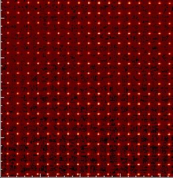
10 Shack-Hartmann spots
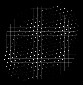
11 Shack-Hartmann spots 45-degree astigmatism
12 Dot relay Lenslets available generally only in fixed sizes; CCD pixels available in fixed sizes; but can adapt lenslet pitch to CCD pixel pitch via relay, often two-lens 4-f telescope for low aberrations/geometric distortion; Relay often necessary anyway because of short lenslet focal lengths and clearance issues Modeled as separate imaging system; dots are objects; entrance pupil is at infinity (telecentric) There is rarely any optical design advantage in modeling the lenslet array as such. Divide design into before-lenslets and after-lenslets. Dot plane Good place for filters CCD plane
13 Dot relay design considerations Once wavefront is sampled by lenslets, the game is over; the wavefront measurement has been made. The relay need only to not blur spot too much, and not introduce unacceptable distortion, which is interpreted as a wavefront error by the WFS. f# is generally slow (e.g., ~ f/20), so re-imaging dots is not difficult. For quad-cell systems, spacing between lenses needs to be perturbed from 4f otherwise there is no dot magnification adjustment possible There is a pupil wrt imaging the dots this is a good place for filters as it after the measurement of the wavefront and affects all subapertures equally. Dot plane Good place for filters CCD plane
14 Spot size/subaperture size Spot size ~λ/d, where d is the subaperture size. Typically, d is on the order of the actuator pitch (often exactly the actuator pitch Fried geometry), and is on the order of r 0 at the science wavelength. For λ 0.8μ and d=40 cm, the spot size is approximately 0.8 μ/0.4m=2 μrad=0.4 arcsec Spot size trade-off bigger subapertures => more light, better SNR in centroid measurement, but poorer fit to wavefront. f subapertures are too small, then spot size increases due to diffraction, degrades spot centroid estimate (proportional to spot size) n example above, 5% spot-size displacement => 0.1 μrad => 0.1 μrad * 0.4 m = 40 nm nm tilt across subaperture
15 Plate scale Plate scale refers to the size in arcsec of a pixel on the CCD of the SH WFS, often ~1-2 arcsec/pixel. Plate scale trade-off Bigger pixels (in arcsec) => more range without crossover between subapertures, but lets in more sky background Could use more pixels per subaperture, but that increases noise in estimate due to read noise/dark current

16 Typical vision science WFS Lenslets CCD Many pixels per subaperture


17 Typical Astronomy WFS Former Keck AO WFS sensor 2 mm 21 μ pixels 3x3 pixels/subap 200 μ lenslets relay lens CCD 3.15 reduction
18 Centroiding Once you have generated spots, how do you determine their positions? The performance of the Shack-Hartmann sensor depends on how well the displacement of the spot is estimated. The displacement is usually estimated using the centroid (center-of-mass) estimator. This is the optimal estimator for the case where the spot is Gaussian distributed and the noise is Poisson. s x = x ( x, y) ( x, y) s y = y ( x, y) ( x, y)
19 Centroiding noise Due to read noise and dark current, all pixels are noisy. Pixels far from the center of the subaperture are multiplied by a large number: s x = x ( x, y) x = { L, 3, 2, 1,0,1,2,3, L} The pixels with the most leverage on the centroid estimate are the dimmest (therefore, the pixels with the least information), and there are lots of dim pixels The more pixels you have, the noisier the centroid estimate!

20 Weighted centroid The noise can be reduced by windowing the centroid:
 ( x, y) s y = yw( x, y) ( x, y)")
21 Weighted centroid Can use a square window, a circular window: Or better still, a tapered window s x = xw( x, y) ( x, y) s y = yw( x, y) ( x, y)

 = argmax( w( x, y) ( x, y)) x y")
22 Correlation (matched filtering) Find the displacement of the image that gives the maximum correlation: ( s, s ) = argmax( w( x, y) ( x, y)) x y =
23 Correlation (matched filtering) Noise is independent of number of pixels Much better noise performance for many pixels Estimate is independent of uniform background errors Estimate is relatively insensitive to assumed image.
24 n astronomy, wavefront slope measurements are often made using a quad cell (2x2 pixels) Quad cells are faster to read and to compute the centroid and less sensitive to noise Quad cells s x = s y =
25 Quad cells The estimated centroid position is linear with displacement only over a small region (small dynamic range) Sensitivity is proportional to spot size Estimated centroid position vs. displacement for different spot sizes Centroid estimated position Displacement
26 Denominator-free centroiding When the photon flux is very low, noise in the denominator increases the centroid error Centroid error can be reduced by using the average value of the denominator s = x E[ ] s = y E[ ]

27 Laser guide elongation Shack-Hartmann subapertures see a line not a spot


28 LGS elongation at Keck Laser projected from right

29 A possible solution for LGS Radial format CCD Arrange pixels to be at same orientation as spots Currently testing this design for TMT elongation laser
 Segmented")
 Rotating phase plates (e.g., Alvarez lens) (Bauman)")
30 Dynamic refocusing for pulsed lasers Powered mirror on mechanical resonator (U of A) Segmented MEMS, one segment per subaperture (Bauman; Baranec) Rotating phase plates (e.g., Alvarez lens) (Bauman)
31 Problems with SH WFS Spot size is large (~ λ/d) Crucial measurement is made at junction between pixel boundaries, which are indistinct (has been reported at ~1/3 pixel charge diffusion) Worst of all worlds: photons near knife-edge generate all the noise and none of the signal!
. At right are observer views of pupil in each case.")
32 Foucault knife-edge test Foucault (1858, 1859 (in French)) Knife-edge test for perfect lens (top), and one with spherical aberration (bottom). At right are observer views of pupil in each case. An irregular mirror tested with knifeedge test
33 Foucault test with mirror
34 Pyramid WFS Pyramid is simultaneous implementation of 4 Foucault knife-edge measurements SH WFS divides aperture into subapertures (via lenslets), then field into quadrants (via pixels) PWFS does in reverse order: pyramid divides field into quadrants (via pyramid) then aperture into subapertures (via pixels) pyramid field lens pupils with CCD pixels demarking subapertures incoming beam CCD at pupil plane image plane
35 PWFS details Pyramids are naturally quite small: Size of pyramid ~ n * (λ*f#), where n is # of subapertures (natural spatial filter) Pyramids have tight fabrication tolerances: Edge precision is a fraction of the full-aperture diffraction spot size (e.g., λ=1μ, f/15 sub-micron precision required. Can make beam slower to relax edge requirements, but at cost of length. Can be made of glass, using cemented facets. Difficult to make sharp edges Can use lenslet-based PWFS (coming up) Note advantage: if edges of pyramid can be sharp, then centroid measurement can be quite precise; indistinct CCD pixel boundaries relegated to subaperture division not crucial Also interesting: as wavefront slopes becomes small, the PWFS becomes a direct phase measuring device
36 SH WFS vs. PWFS Geometrically, identical just remapping of pixels. Diffractive advantage appears in high- Strehl regime.

.")
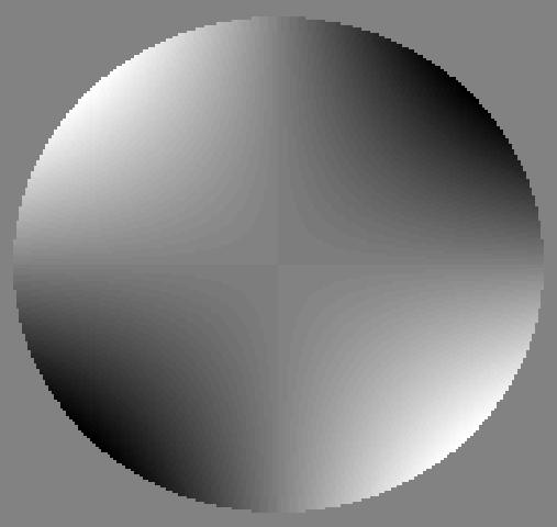
37 Pyramid wave-front sensor non-linearity When the aberrations are large (e.g., defocus below), the pyramid sensor is very non-linear (reaches saturation). 4 pupil images x- and y-slopes estimates.
38 Modulation of pyramid sensor Without modulation: Linear over spot width With modulation: Linear over modulation width
39 Another pyramid implementation: Pyramid + lens = 2x2 lenslet array Lenslets are inexpensive and easily replicated. The right manufacturing technique produces sharp boundaries between lenslets (where all the action is). pyramid field lens lenslets Bauman dissertation
 at the edge of an aperture Pupils should not be too close to avoid contamination between pupil images mage of PWFS Johnson, et al.")
40 Brightening of rim is real effect PWFS is not quite a slope detector, but a derivative detector (effect also seen in knife-edge tests) There is a large derivative (in amplitude) at the edge of an aperture Pupils should not be too close to avoid contamination between pupil images mage of PWFS Johnson, et al., 2006
41 Curvature sensing -z mage 2 Aperture Wave-front at aperture z mage 1
42 Curvature sensing Developed by Roddier for AO in Linear relationship between the curvature in the aperture and the normalized intensity difference: Broadband light helps reduce diffraction effects. Tends to be used in lowerorder systems (i.e., fewer subapertures/actuators, because of higher error propagation z = f f l ( f l) l Aperture Defocused image 1 Defocused image 2
43 Curvature sensing W W z =. 2 where is the intensity, W is the wavefront and z is the direction of propagation, we obtain a linear, first-order approximation, which is a Poisson equation with Neumann boundary conditions. Using the irradiance transport equation, W z W z + =
44 Solution at the boundary ) ( ) ( ) ( ) ( x x x x zw R x H zw R x H zw R x H zw R x H = f the intensity is constant at the aperture,
45 Solution inside the boundary = z( W xx + W yy ) Curvature There is a linear relationship between the signal and the curvature The sensor is more sensitive for large effective propagation distances
46 Curvature sensing As the propagation distance, z, increases, sensitivity increases. Spatial resolution decreases. Diffraction effects increase = z( W xx + W yy ) The relationship between the signal, ( 1-2 )/( ) and the curvature, W xx + W yy, becomes non-linear
47 Curvature sensing Practical implementation uses a variable curvature mirror (to obtain images below and above the aperture) and a single detector.
 Detect individual photons no read")
48 Curvature sensor subapertures Measure intensity in each subaperture with an avalanche photo-diode (APD) Detect individual photons no read noise
Wavefront sensing for adaptive optics
 Wavefront sensing for adaptive optics Richard Dekany Caltech Optical Observatories 2009 Thanks to: Acknowledgments Marcos van Dam original screenplay Brian Bauman adapted screenplay Contributors Richard
Wavefront Sensing In Other Disciplines. 15 February 2003 Jerry Nelson, UCSC Wavefront Congress
 Wavefront Sensing In Other Disciplines 15 February 2003 Jerry Nelson, UCSC Wavefront Congress QuickTime and a Photo - JPEG decompressor are needed to see this picture. 15feb03 Nelson wavefront sensing
Lecture 7: Wavefront Sensing Claire Max Astro 289C, UCSC February 2, 2016
 Lecture 7: Wavefront Sensing Claire Max Astro 289C, UCSC February 2, 2016 Page 1 Outline of lecture General discussion: Types of wavefront sensors Three types in more detail: Shack-Hartmann wavefront sensors
Adaptive Optics for LIGO
 Adaptive Optics for LIGO Justin Mansell Ginzton Laboratory LIGO-G990022-39-M Motivation Wavefront Sensor Outline Characterization Enhancements Modeling Projections Adaptive Optics Results Effects of Thermal
Adaptive Optics lectures
 Adaptive Optics lectures 2. Adaptive optics Invented in 1953 by H.Babcock Andrei Tokovinin 1 Plan General idea (open/closed loop) Wave-front sensing, its limitations Correctors (DMs) Control (spatial and
Effect of segmented telescope phasing errors on adaptive optics performance
 Effect of segmented telescope phasing errors on adaptive optics performance Marcos van Dam Flat Wavefronts Sam Ragland & Peter Wizinowich W.M. Keck Observatory Motivation Keck II AO / NIRC2 K-band Strehl
NGAO NGS WFS design review
 NGAO NGS WFS design review Caltech Optical 1 st April2010 1 Presentation outline Requirements (including modes of operation and motion control) Introduction NGSWFS input feed (performance of the triplet
Explanation of Aberration and Wavefront
 Explanation of Aberration and Wavefront 1. What Causes Blur? 2. What is? 4. What is wavefront? 5. Hartmann-Shack Aberrometer 6. Adoption of wavefront technology David Oh 1. What Causes Blur? 2. What is?
Why is There a Black Dot when Defocus = 1λ?
 Why is There a Black Dot when Defocus = 1λ? W = W 020 = a 020 ρ 2 When a 020 = 1λ Sag of the wavefront at full aperture (ρ = 1) = 1λ Sag of the wavefront at ρ = 0.707 = 0.5λ Area of the pupil from ρ =
KAPAO: Design and Assembly of the Wavefront Sensor for an Adaptive Optics Instrument
 KAPAO: Design and Assembly of the Wavefront Sensor for an Adaptive Optics Instrument by Daniel Savino Contreras A thesis submitted in partial fulfillment for the degree of Bachelor of Arts in Physics and
Vision Research at. Validation of a Novel Hartmann-Moiré Wavefront Sensor with Large Dynamic Range. Wavefront Science Congress, Feb.
 Wavefront Science Congress, Feb. 2008 Validation of a Novel Hartmann-Moiré Wavefront Sensor with Large Dynamic Range Xin Wei 1, Tony Van Heugten 2, Nikole L. Himebaugh 1, Pete S. Kollbaum 1, Mei Zhang
Optical design of a high resolution vision lens
 Optical design of a high resolution vision lens Paul Claassen, optical designer, paul.claassen@sioux.eu Marnix Tas, optical specialist, marnix.tas@sioux.eu Prof L.Beckmann, l.beckmann@hccnet.nl Summary:
Proposed Adaptive Optics system for Vainu Bappu Telescope
 Proposed Adaptive Optics system for Vainu Bappu Telescope Essential requirements of an adaptive optics system Adaptive Optics is a real time wave front error measurement and correction system The essential
Ron Liu OPTI521-Introductory Optomechanical Engineering December 7, 2009
 Synopsis of METHOD AND APPARATUS FOR IMPROVING VISION AND THE RESOLUTION OF RETINAL IMAGES by David R. Williams and Junzhong Liang from the US Patent Number: 5,777,719 issued in July 7, 1998 Ron Liu OPTI521-Introductory
Cardinal Points of an Optical System--and Other Basic Facts
 Cardinal Points of an Optical System--and Other Basic Facts The fundamental feature of any optical system is the aperture stop. Thus, the most fundamental optical system is the pinhole camera. The image
Geometrical Optics for AO Claire Max UC Santa Cruz CfAO 2009 Summer School
 Geometrical Optics for AO Claire Max UC Santa Cruz CfAO 2009 Summer School Page 1 Some tools for active learning In-class conceptual questions will aim to engage you in more active learning and provide
Wavefront control for highcontrast
 Wavefront control for highcontrast imaging Lisa A. Poyneer In the Spirit of Bernard Lyot: The direct detection of planets and circumstellar disks in the 21st century. Berkeley, CA, June 6, 2007 p Gemini
Modeling the multi-conjugate adaptive optics system of the E-ELT. Laura Schreiber Carmelo Arcidiacono Giovanni Bregoli
 Modeling the multi-conjugate adaptive optics system of the E-ELT Laura Schreiber Carmelo Arcidiacono Giovanni Bregoli MAORY E-ELT Multi Conjugate Adaptive Optics Relay Wavefront sensing based on 6 (4)
Figure 7 Dynamic range expansion of Shack- Hartmann sensor using a spatial-light modulator
 Figure 4 Advantage of having smaller focal spot on CCD with super-fine pixels: Larger focal point compromises the sensitivity, spatial resolution, and accuracy. Figure 1 Typical microlens array for Shack-Hartmann
Shaping light in microscopy:
 Shaping light in microscopy: Adaptive optical methods and nonconventional beam shapes for enhanced imaging Martí Duocastella planet detector detector sample sample Aberrated wavefront Beamsplitter Adaptive
APPLICATION NOTE
 THE PHYSICS BEHIND TAG OPTICS TECHNOLOGY AND THE MECHANISM OF ACTION OF APPLICATION NOTE 12-001 USING SOUND TO SHAPE LIGHT Page 1 of 6 Tutorial on How the TAG Lens Works This brief tutorial explains the
Adaptive Optics Phoropters
 Adaptive Optics Phoropters Scot S. Olivier Adaptive Optics Group Leader Physics and Advanced Technologies Lawrence Livermore National Laboratory Associate Director NSF Center for Adaptive Optics Adaptive
AgilEye Manual Version 2.0 February 28, 2007
 AgilEye Manual Version 2.0 February 28, 2007 1717 Louisiana NE Suite 202 Albuquerque, NM 87110 (505) 268-4742 support@agiloptics.com 2 (505) 268-4742 v. 2.0 February 07, 2007 3 Introduction AgilEye Wavefront
EE119 Introduction to Optical Engineering Fall 2009 Final Exam. Name:
 EE119 Introduction to Optical Engineering Fall 2009 Final Exam Name: SID: CLOSED BOOK. THREE 8 1/2 X 11 SHEETS OF NOTES, AND SCIENTIFIC POCKET CALCULATOR PERMITTED. TIME ALLOTTED: 180 MINUTES Fundamental
Comparative Performance of a 3-Sided and 4-Sided Pyramid Wavefront Sensor. HartSCI LLC, 2555 N. Coyote Dr. #114, Tucson, AZ
 Comparative Performance of a 3-Sided and 4-Sided Pyramid Wavefront Sensor Johanan L. Codona 3, Michael Hart 1,2, Lauren H. Schatz 2, and Mala Mateen 3 1 HartSCI LLC, 2555 N. Coyote Dr. #114, Tucson, AZ
High contrast imaging lab
 High contrast imaging lab Ay122a, November 2016, D. Mawet Introduction This lab is an introduction to high contrast imaging, and in particular coronagraphy and its interaction with adaptive optics sytems.
The Wavefront Control System for the Keck Telescope
 UCRL-JC-130919 PREPRINT The Wavefront Control System for the Keck Telescope J.M. Brase J. An K. Avicola B.V. Beeman D.T. Gavel R. Hurd B. Johnston H. Jones T. Kuklo C.E. Max S.S. Olivier K.E. Waltjen J.
Reflectors vs. Refractors
 1 Telescope Types - Telescopes collect and concentrate light (which can then be magnified, dispersed as a spectrum, etc). - In the end it is the collecting area that counts. - There are two primary telescope
Multi aperture coherent imaging IMAGE testbed
 Multi aperture coherent imaging IMAGE testbed Nick Miller, Joe Haus, Paul McManamon, and Dave Shemano University of Dayton LOCI Dayton OH 16 th CLRC Long Beach 20 June 2011 Aperture synthesis (part 1 of
CHARA AO Calibration Process
 CHARA AO Calibration Process Judit Sturmann CHARA AO Project Overview Phase I. Under way WFS on telescopes used as tip-tilt detector Phase II. Not yet funded WFS and large DM in place of M4 on telescopes
Ocular Shack-Hartmann sensor resolution. Dan Neal Dan Topa James Copland
 Ocular Shack-Hartmann sensor resolution Dan Neal Dan Topa James Copland Outline Introduction Shack-Hartmann wavefront sensors Performance parameters Reconstructors Resolution effects Spot degradation Accuracy
Aberrations and adaptive optics for biomedical microscopes
 Aberrations and adaptive optics for biomedical microscopes Martin Booth Department of Engineering Science And Centre for Neural Circuits and Behaviour University of Oxford Outline Rays, wave fronts and
Lecture 2: Geometrical Optics. Geometrical Approximation. Lenses. Mirrors. Optical Systems. Images and Pupils. Aberrations.
 Lecture 2: Geometrical Optics Outline 1 Geometrical Approximation 2 Lenses 3 Mirrors 4 Optical Systems 5 Images and Pupils 6 Aberrations Christoph U. Keller, Leiden Observatory, keller@strw.leidenuniv.nl
12.4 Alignment and Manufacturing Tolerances for Segmented Telescopes
 330 Chapter 12 12.4 Alignment and Manufacturing Tolerances for Segmented Telescopes Similar to the JWST, the next-generation large-aperture space telescope for optical and UV astronomy has a segmented
Lecture 2: Geometrical Optics. Geometrical Approximation. Lenses. Mirrors. Optical Systems. Images and Pupils. Aberrations.
 Lecture 2: Geometrical Optics Outline 1 Geometrical Approximation 2 Lenses 3 Mirrors 4 Optical Systems 5 Images and Pupils 6 Aberrations Christoph U. Keller, Leiden Observatory, keller@strw.leidenuniv.nl
EE119 Introduction to Optical Engineering Spring 2003 Final Exam. Name:
 EE119 Introduction to Optical Engineering Spring 2003 Final Exam Name: SID: CLOSED BOOK. THREE 8 1/2 X 11 SHEETS OF NOTES, AND SCIENTIFIC POCKET CALCULATOR PERMITTED. TIME ALLOTTED: 180 MINUTES Fundamental
PYRAMID WAVEFRONT SENSOR PERFORMANCE WITH LASER GUIDE STARS
 Florence, Italy. Adaptive May 2013 Optics for Extremely Large Telescopes III ISBN: 978-88-908876-0-4 DOI: 10.12839/AO4ELT3.13138 PYRAMID WAVEFRONT SENSOR PERFORMANCE WITH LASER GUIDE STARS Fernando Quirós-Pacheco
3.0 Alignment Equipment and Diagnostic Tools:
 3.0 Alignment Equipment and Diagnostic Tools: Alignment equipment The alignment telescope and its use The laser autostigmatic cube (LACI) interferometer A pin -- and how to find the center of curvature
Design parameters Summary
 634 Entrance pupil diameter 100-m Entrance pupil location Primary mirror Exit pupil location On M6 Focal ratio 6.03 Plate scale 2.924 mm / arc second (on-axis) Total field of view 10 arc minutes (unvignetted)
DESIGN NOTE: DIFFRACTION EFFECTS
 NASA IRTF / UNIVERSITY OF HAWAII Document #: TMP-1.3.4.2-00-X.doc Template created on: 15 March 2009 Last Modified on: 5 April 2010 DESIGN NOTE: DIFFRACTION EFFECTS Original Author: John Rayner NASA Infrared
Lecture 4: Geometrical Optics 2. Optical Systems. Images and Pupils. Rays. Wavefronts. Aberrations. Outline
 Lecture 4: Geometrical Optics 2 Outline 1 Optical Systems 2 Images and Pupils 3 Rays 4 Wavefronts 5 Aberrations Christoph U. Keller, Leiden University, keller@strw.leidenuniv.nl Lecture 4: Geometrical
A prototype of the Laser Guide Stars wavefront sensor for the E-ELT multi-conjugate adaptive optics module
 1st AO4ELT conference, 05020 (2010) DOI:10.1051/ao4elt/201005020 Owned by the authors, published by EDP Sciences, 2010 A prototype of the Laser Guide Stars wavefront sensor for the E-ELT multi-conjugate
MAORY E-ELT MCAO module project overview
 MAORY E-ELT MCAO module project overview Emiliano Diolaiti Istituto Nazionale di Astrofisica Osservatorio Astronomico di Bologna On behalf of the MAORY Consortium AO4ELT3, Firenze, 27-31 May 2013 MAORY
Bruce Macintosh for the GPI team Presented at the Spirit of Lyot conference June 7, 2007
 This work was performed under the auspices of the U.S. Department of Energy by University of California, Lawrence Livermore National Laboratory under Contract W-7405-Eng-48. Bruce Macintosh for the GPI
Computer Generated Holograms for Optical Testing
 Computer Generated Holograms for Optical Testing Dr. Jim Burge Associate Professor Optical Sciences and Astronomy University of Arizona jburge@optics.arizona.edu 520-621-8182 Computer Generated Holograms
Chapter Ray and Wave Optics
 109 Chapter Ray and Wave Optics 1. An astronomical telescope has a large aperture to [2002] reduce spherical aberration have high resolution increase span of observation have low dispersion. 2. If two
1.6 Beam Wander vs. Image Jitter
 8 Chapter 1 1.6 Beam Wander vs. Image Jitter It is common at this point to look at beam wander and image jitter and ask what differentiates them. Consider a cooperative optical communication system that
Effect of segmented telescope phasing errors on adaptive optics performance
 Effect of segmented telescope phasing errors on adaptive optics performance Marcos A. van Dam a, Sam Ragland b, and Peter L. Wizinowich b a Flat Wavefronts, 21 Lascelles Street, Christchurch 8022, New
Improving techniques for Shack-Hartmann wavefront sensing: dynamic-range and frame rate
 Improving techniques for Shack-Hartmann wavefront sensing: dynamic-range and frame rate Takao Endo, Yoshichika Miwa, Jiro Suzuki and Toshiyuki Ando Information Technology R&D Center, Mitsubishi Electric
 Telecentric Imaging Object space telecentricity stop source: edmund optics The 5 classical Seidel Aberrations First order aberrations Spherical Aberration (~r 4 ) Origin: different focal lengths for different
Chapter 36. Image Formation
 Chapter 36 Image Formation Image of Formation Images can result when light rays encounter flat or curved surfaces between two media. Images can be formed either by reflection or refraction due to these
Metrology and Sensing
 Metrology and Sensing Lecture 7: Wavefront sensors 2016-11-29 Herbert Gross Winter term 2016 www.iap.uni-jena.de 2 Preliminary Schedule No Date Subject Detailed Content 1 18.10. Introduction Introduction,
Chapter 36. Image Formation
 Chapter 36 Image Formation Notation for Mirrors and Lenses The object distance is the distance from the object to the mirror or lens Denoted by p The image distance is the distance from the image to the
AY122A - Adaptive Optics Lab
 AY122A - Adaptive Optics Lab Purpose In this lab, after an introduction to turbulence and adaptive optics for astronomy, you will get to experiment first hand the three main components of an adaptive optics
Point Spread Function. Confocal Laser Scanning Microscopy. Confocal Aperture. Optical aberrations. Alternative Scanning Microscopy
 Bi177 Lecture 5 Adding the Third Dimension Wide-field Imaging Point Spread Function Deconvolution Confocal Laser Scanning Microscopy Confocal Aperture Optical aberrations Alternative Scanning Microscopy
Optical Components for Laser Applications. Günter Toesko - Laserseminar BLZ im Dezember
 Günter Toesko - Laserseminar BLZ im Dezember 2009 1 Aberrations An optical aberration is a distortion in the image formed by an optical system compared to the original. It can arise for a number of reasons
Chapter 25. Optical Instruments
 Chapter 25 Optical Instruments Optical Instruments Analysis generally involves the laws of reflection and refraction Analysis uses the procedures of geometric optics To explain certain phenomena, the wave
MALA MATEEN. 1. Abstract
 IMPROVING THE SENSITIVITY OF ASTRONOMICAL CURVATURE WAVEFRONT SENSOR USING DUAL-STROKE CURVATURE: A SYNOPSIS MALA MATEEN 1. Abstract Below I present a synopsis of the paper: Improving the Sensitivity of
INTRODUCTION TO ABERRATIONS IN OPTICAL IMAGING SYSTEMS
 INTRODUCTION TO ABERRATIONS IN OPTICAL IMAGING SYSTEMS JOSE SASIÄN University of Arizona ШШ CAMBRIDGE Щ0 UNIVERSITY PRESS Contents Preface Acknowledgements Harold H. Hopkins Roland V. Shack Symbols 1 Introduction
Puntino. Shack-Hartmann wavefront sensor for optimizing telescopes. The software people for optics
 Puntino Shack-Hartmann wavefront sensor for optimizing telescopes 1 1. Optimize telescope performance with a powerful set of tools A finely tuned telescope is the key to obtaining deep, high-quality astronomical
Optimization of Existing Centroiding Algorithms for Shack Hartmann Sensor
 Proceeding of the National Conference on Innovative Computational Intelligence & Security Systems Sona College of Technology, Salem. Apr 3-4, 009. pp 400-405 Optimization of Existing Centroiding Algorithms
Optical System Design
 Phys 531 Lecture 12 14 October 2004 Optical System Design Last time: Surveyed examples of optical systems Today, discuss system design Lens design = course of its own (not taught by me!) Try to give some
Light gathering Power: Magnification with eyepiece:
 Telescopes Light gathering Power: The amount of light that can be gathered by a telescope in a given amount of time: t 1 /t 2 = (D 2 /D 1 ) 2 The larger the diameter the smaller the amount of time. If
Focal Plane and non-linear Curvature Wavefront Sensing for High Contrast Coronagraphic Adaptive Optics Imaging
 Focal Plane and non-linear Curvature Wavefront Sensing for High Contrast Coronagraphic Adaptive Optics Imaging Olivier Guyon Subaru Telescope 640 N. A'ohoku Pl. Hilo, HI 96720 USA Abstract Wavefronts can
Wavefront sensing by an aperiodic diffractive microlens array
 Wavefront sensing by an aperiodic diffractive microlens array Lars Seifert a, Thomas Ruppel, Tobias Haist, and Wolfgang Osten a Institut für Technische Optik, Universität Stuttgart, Pfaffenwaldring 9,
Designing Adaptive Optics Systems
 Designing Adaptive Optics Systems Donald Gavel UCO/Lick Observatory Laboratory for Adaptive Optics Designing Adaptive Optics Systems Outline The design process AO systems taxonomy Commonalities and differences
Wavefront sensor design for NGAO: Assumptions, Design Parameters and Technical Challenges Version 0.1
 Wavefront sensor design for NGAO: Assumptions, Design Parameters and Technical Challenges Version 0.1 V. Velur Caltech Optical Observatories M/S 105-24, 1200 E California Blvd., Pasadena, CA 91125 Sept.
A Ground-based Sensor to Detect GEOs Without the Use of a Laser Guide-star
 A Ground-based Sensor to Detect GEOs Without the Use of a Laser Guide-star Mala Mateen Air Force Research Laboratory, Kirtland AFB, NM, 87117 Olivier Guyon Subaru Telescope, Hilo, HI, 96720 Michael Hart,
Long-Range Adaptive Passive Imaging Through Turbulence
 / APPROVED FOR PUBLIC RELEASE Long-Range Adaptive Passive Imaging Through Turbulence David Tofsted, with John Blowers, Joel Soto, Sean D Arcy, and Nathan Tofsted U.S. Army Research Laboratory RDRL-CIE-D
Big League Cryogenics and Vacuum The LHC at CERN
 Big League Cryogenics and Vacuum The LHC at CERN A typical astronomical instrument must maintain about one cubic meter at a pressure of
Null Hartmann test for the fabrication of large aspheric surfaces
 Null Hartmann test for the fabrication of large aspheric surfaces Ho-Soon Yang, Yun-Woo Lee, Jae-Bong Song, and In-Won Lee Korea Research Institute of Standards and Science, P.O. Box 102, Yuseong, Daejon
VC 11/12 T2 Image Formation
 VC 11/12 T2 Image Formation Mestrado em Ciência de Computadores Mestrado Integrado em Engenharia de Redes e Sistemas Informáticos Miguel Tavares Coimbra Outline Computer Vision? The Human Visual System
Criteria for Optical Systems: Optical Path Difference How do we determine the quality of a lens system? Several criteria used in optical design
 Criteria for Optical Systems: Optical Path Difference How do we determine the quality of a lens system? Several criteria used in optical design Computer Aided Design Several CAD tools use Ray Tracing (see
Physics 431 Final Exam Examples (3:00-5:00 pm 12/16/2009) TIME ALLOTTED: 120 MINUTES Name: Signature:
 TIME ALLOTTED: 120 MINUTES Name: Signature:") Physics 431 Final Exam Examples (3:00-5:00 pm 12/16/2009) TIME ALLOTTED: 120 MINUTES Name: PID: Signature: CLOSED BOOK. TWO 8 1/2 X 11 SHEET OF NOTES (double sided is allowed), AND SCIENTIFIC POCKET CALCULATOR
Physics 431 Final Exam Examples (3:00-5:00 pm 12/16/2009) TIME ALLOTTED: 120 MINUTES Name: PID: Signature: CLOSED BOOK. TWO 8 1/2 X 11 SHEET OF NOTES (double sided is allowed), AND SCIENTIFIC POCKET CALCULATOR
DESIGNING AND IMPLEMENTING AN ADAPTIVE OPTICS SYSTEM FOR THE UH HOKU KE`A OBSERVATORY ABSTRACT
 DESIGNING AND IMPLEMENTING AN ADAPTIVE OPTICS SYSTEM FOR THE UH HOKU KE`A OBSERVATORY University of Hawai`i at Hilo Alex Hedglen ABSTRACT The presented project is to implement a small adaptive optics system
Calibration of AO Systems
 Calibration of AO Systems Application to NAOS-CONICA and future «Planet Finder» systems T. Fusco, A. Blanc, G. Rousset Workshop Pueo Nu, may 2003 Département d Optique Théorique et Appliquée ONERA, Châtillon
The Formation of an Aerial Image, part 3
 T h e L i t h o g r a p h y T u t o r (July 1993) The Formation of an Aerial Image, part 3 Chris A. Mack, FINLE Technologies, Austin, Texas In the last two issues, we described how a projection system
Optical Design of. Microscopes. George H. Seward. Tutorial Texts in Optical Engineering Volume TT88. SPIE PRESS Bellingham, Washington USA
 Optical Design of Microscopes George H. Seward Tutorial Texts in Optical Engineering Volume TT88 SPIE PRESS Bellingham, Washington USA Preface xiii Chapter 1 Optical Design Concepts /1 1.1 A Value Proposition
What is Wavefront Aberration? Custom Contact Lenses For Vision Improvement Are They Feasible In A Disposable World?
 Custom Contact Lenses For Vision Improvement Are They Feasible In A Disposable World? Ian Cox, BOptom, PhD, FAAO Distinguished Research Fellow Bausch & Lomb, Rochester, NY Acknowledgements Center for Visual
Paper Synopsis. Xiaoyin Zhu Nov 5, 2012 OPTI 521
 Paper Synopsis Xiaoyin Zhu Nov 5, 2012 OPTI 521 Paper: Active Optics and Wavefront Sensing at the Upgraded 6.5-meter MMT by T. E. Pickering, S. C. West, and D. G. Fabricant Abstract: This synopsis summarized
J. C. Wyant Fall, 2012 Optics Optical Testing and Testing Instrumentation
 J. C. Wyant Fall, 2012 Optics 513 - Optical Testing and Testing Instrumentation Introduction 1. Measurement of Paraxial Properties of Optical Systems 1.1 Thin Lenses 1.1.1 Measurements Based on Image Equation
An Update on the Installation of the AO on the Telescopes
 An Update on the Installation of the AO on the Telescopes Laszlo Sturmann Overview Phase I WFS on the telescopes separate WFS and DM in the lab (LABAO) Phase II (unfunded) large DM replaces M4 F/8 PAR
WaveMaster IOL. Fast and accurate intraocular lens tester
 WaveMaster IOL Fast and accurate intraocular lens tester INTRAOCULAR LENS TESTER WaveMaster IOL Fast and accurate intraocular lens tester WaveMaster IOL is a new instrument providing real time analysis
Image Formation. Light from distant things. Geometrical optics. Pinhole camera. Chapter 36
 Light from distant things Chapter 36 We learn about a distant thing from the light it generates or redirects. The lenses in our eyes create images of objects our brains can process. This chapter concerns
Breadboard adaptive optical system based on 109-channel PDM: technical passport
 F L E X I B L E Flexible Optical B.V. Adaptive Optics Optical Microsystems Wavefront Sensors O P T I C A L Oleg Soloviev Chief Scientist Röntgenweg 1 2624 BD, Delft The Netherlands Tel: +31 15 285 15-47
Computational Cameras. Rahul Raguram COMP
 Computational Cameras Rahul Raguram COMP 790-090 What is a computational camera? Camera optics Camera sensor 3D scene Traditional camera Final image Modified optics Camera sensor Image Compute 3D scene
ECEG105/ECEU646 Optics for Engineers Course Notes Part 4: Apertures, Aberrations Prof. Charles A. DiMarzio Northeastern University Fall 2008
 ECEG105/ECEU646 Optics for Engineers Course Notes Part 4: Apertures, Aberrations Prof. Charles A. DiMarzio Northeastern University Fall 2008 July 2003+ Chuck DiMarzio, Northeastern University 11270-04-1
Non-adaptive Wavefront Control
 OWL Phase A Review - Garching - 2 nd to 4 th Nov 2005 Non-adaptive Wavefront Control (Presented by L. Noethe) 1 Specific problems in ELTs and OWL Concentrate on problems which are specific for ELTs and,
Some of the important topics needed to be addressed in a successful lens design project (R.R. Shannon: The Art and Science of Optical Design)
") Lens design Some of the important topics needed to be addressed in a successful lens design project (R.R. Shannon: The Art and Science of Optical Design) Focal length (f) Field angle or field size F/number
Lens design Some of the important topics needed to be addressed in a successful lens design project (R.R. Shannon: The Art and Science of Optical Design) Focal length (f) Field angle or field size F/number
Dynamic Phase-Shifting Electronic Speckle Pattern Interferometer
 Dynamic Phase-Shifting Electronic Speckle Pattern Interferometer Michael North Morris, James Millerd, Neal Brock, John Hayes and *Babak Saif 4D Technology Corporation, 3280 E. Hemisphere Loop Suite 146,
Shack Hartmann Sensor Based on a Low-Aperture Off-Axis Diffraction Lens Array
 ISSN 8756-699, Optoelectronics, Instrumentation and Data Processing, 29, Vol. 45, No. 2, pp. 6 7. c Allerton Press, Inc., 29. Original Russian Text c V.P. Lukin, N.N. Botygina, O.N. Emaleev, V.P. Korol
OPTINO. SpotOptics VERSATILE WAVEFRONT SENSOR O P T I N O
 Spotptics he software people for optics VERSALE WAVEFR SESR Accurate metrology in single and double pass Lenses, mirrors and laser beams Any focal length and diameter Large dynamic range Adaptable for
Properties of Structured Light
 Properties of Structured Light Gaussian Beams Structured light sources using lasers as the illumination source are governed by theories of Gaussian beams. Unlike incoherent sources, coherent laser sources
Design of wide-field imaging shack Hartmann testbed
 Design of wide-field imaging shack Hartmann testbed Item Type Article Authors Schatz, Lauren H.; Scott, R. Phillip; Bronson, Ryan S.; Sanchez, Lucas R. W.; Hart, Michael Citation Lauren H. Schatz ; R.
Hartmann-Shack sensor ASIC s for real-time adaptive optics in biomedical physics
 Hartmann-Shack sensor ASIC s for real-time adaptive optics in biomedical physics Thomas NIRMAIER Kirchhoff Institute, University of Heidelberg Heidelberg, Germany Dirk DROSTE Robert Bosch Group Stuttgart,
Using molded chalcogenide glass technology to reduce cost in a compact wide-angle thermal imaging lens
 Using molded chalcogenide glass technology to reduce cost in a compact wide-angle thermal imaging lens George Curatu a, Brent Binkley a, David Tinch a, and Costin Curatu b a LightPath Technologies, 2603
ABSTRACT 1. INTRODUCTION
 Design and performance of a new compact adaptable autostigmatic alignment tool William P. Kuhn Opt-E, 3450 S Broadmont Dr Ste 112, Tucson, AZ, USA 85713-5245 bill.kuhn@opt-e.com ABSTRACT The design and
PHY 431 Homework Set #5 Due Nov. 20 at the start of class
 PHY 431 Homework Set #5 Due Nov. 0 at the start of class 1) Newton s rings (10%) The radius of curvature of the convex surface of a plano-convex lens is 30 cm. The lens is placed with its convex side down
FRAUNHOFER AND FRESNEL DIFFRACTION IN ONE DIMENSION
 FRAUNHOFER AND FRESNEL DIFFRACTION IN ONE DIMENSION Revised November 15, 2017 INTRODUCTION The simplest and most commonly described examples of diffraction and interference from two-dimensional apertures
PROCEEDINGS OF SPIE. Measurement of low-order aberrations with an autostigmatic microscope
 PROCEEDINGS OF SPIE SPIEDigitalLibrary.org/conference-proceedings-of-spie Measurement of low-order aberrations with an autostigmatic microscope William P. Kuhn Measurement of low-order aberrations with