MyStudio VS53 Versa Sweep Setup Instructions
|
|
|
- Tiffany Moore
- 5 years ago
- Views:
Transcription
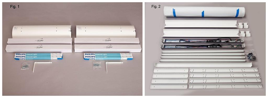
1 MyStudio VS53 Versa Sweep Setup Instructions MISSION STATEMENT Pro Cyc, Inc. is the world leader in design and sales of modular infinity backgrounds. Our studio systems are recommended by every major company providing chroma key and virtual technology to the film, video and still photography markets. The MyStudio line continues our tradition by bringing Pro Cyc advantages to the home user, providing the very best to our customers. MyStudio gives you the best results possible to accurately portray your products and produce perfectly lit, professional quality photos with virtually no prior photography experience. You will need the following tools: Phillips screwdriver (Flathead screwdriver is optional for all ¼ -20 x 1/2 screws) 7/16 (11mm) wrench or nut driver, or crescent wrench Your contents include the following items, separated below for both the AL2 Accent Lights and the VS53 Versa Sweep Photo Studio. We recommend separating the parts out for each item before beginning assembly: 2 x AL2 Accent Lights: (Fig. 1) 1) 2 24 powder coated aluminum housings 2) 2 powder coated aluminum L-brackets 3) 4 fluorescent lamp fixtures 4) K daylight fluorescent light bulbs 5) Hardware included: two sealed packets, each with six ¼ -20 x 1/2 screws; six ¼ - 20 hex nuts VS53 Versa Sweep Photo Studio: (Fig. 2) 1) 1-53 W x 96 L white background roll 2) 2 48 long powder coated white aluminum light reflectors 3) 1 48 long powder coated white aluminum crossbar 4) 2 48 T8 fluorescent lamp fixtures 5) 4 48 daylight fluorescent light bulbs 6) 4 powder coated white aluminum legs 7) 4 powder coated white aluminum feet 8) 4 powder coated white light support brackets 9) 5 2 background clips 10) Hardware packet includes: eight ¼ -20 x 1/2 screws eight ¼ -20 hex nuts twelve ¼ -20 x 1/2 thumb screws (with black knobs) eight 3/16 zinc plated washers four #10-24 x 3 pan head screws four #10-24 wing nuts AL2 Accent Lights Assembly Separate out the parts for the AL2 accent lights (Fig.1) and see separate instruction sheet included for complete accent light assembly instructions.
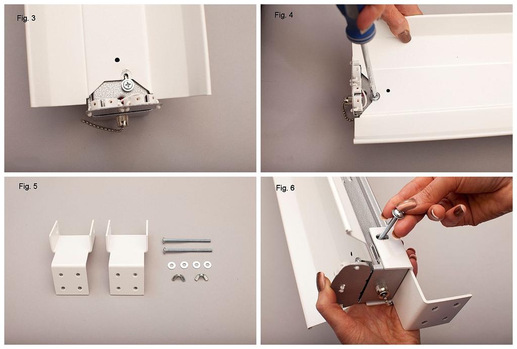
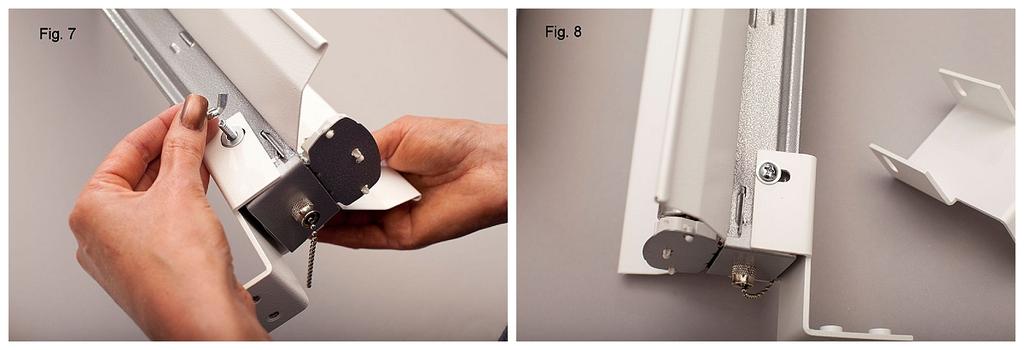
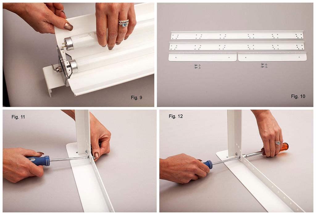
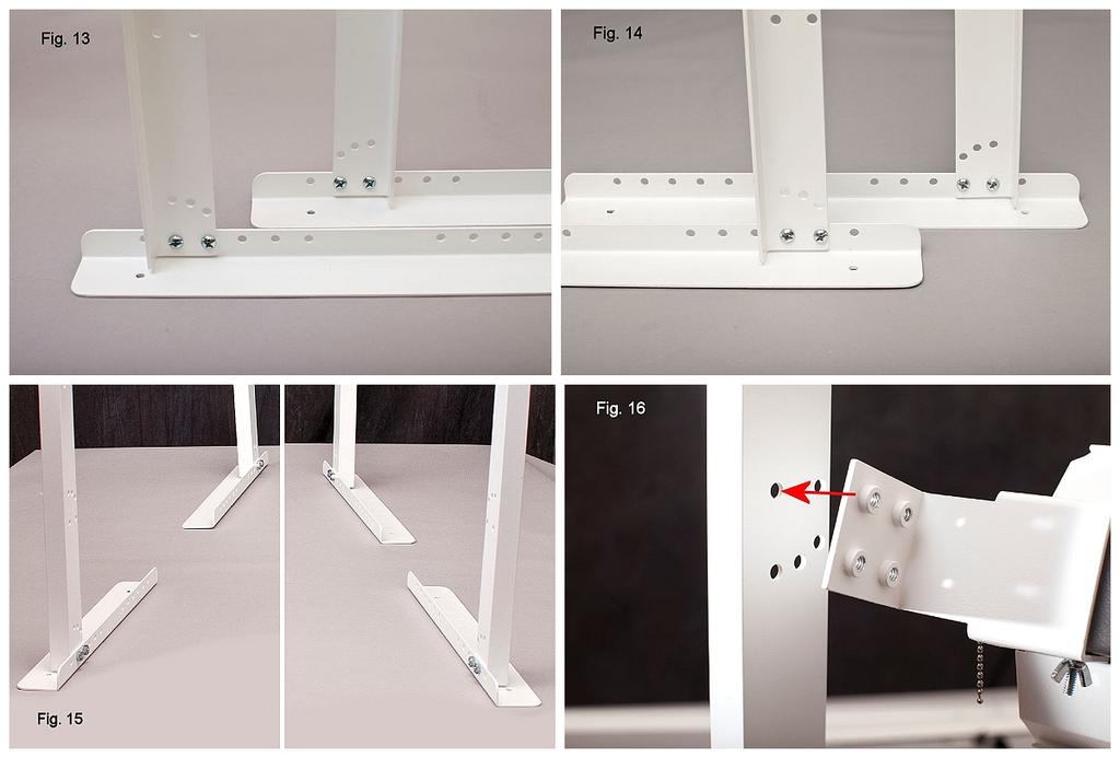
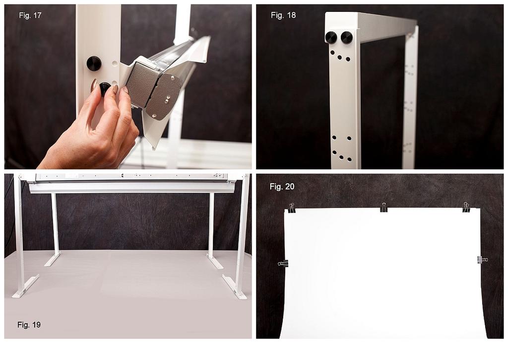
2 VS53 Versa Sweep Photo Studio Assembly 1. Light assembly: (follow steps a thru c below for both light fixtures) a) Reflectors First, remove the loosened screw on the end of the lamp that is not attached to the green wire. Then take one 48 long powder coated white aluminum light reflector and attach it, concave side up, over the exposed part of one of the 48 fluorescent lamp fixtures. To attach, slide the notched part of the reflector at one end under the loosened screw on the lamp fixture (Fig. 3) and tighten with a Phillips screwdriver (Fig. 4). Repeat on the other end of the lamp. b) Brackets Using the pieces shown in Fig. 5 for each lamp, attach one bracket to each side of the lamp. To attach, position the bracket over one end of the lamp as shown in Fig. 6, and line up the holes in the bracket with the holes in the metal lamp housing. Put one 3/16 washer over the end of a #10-24 x 3 pan head screw and insert it through the top side of the bracket (Fig. 6), through the lamp and through the hole in the bracket on the other side. Secure with 3/16 washer and a #10-24 wing nut and finger-tighten (Figs. 7, 8). Note: the clamps do not have to be super tight once they are mounted on the stand they will be secure. c) Light bulbs with the lamp laying flat on its back resting on the brackets, install both 48 fluorescent bulbs one at a time by lining up the pins on either end of the bulb with the slots in the lamp (Fig. 9). Push the bulb down carefully until it is snug on both ends, then twist it about ¼ turn until it clicks into place. 2. Legs and Feet assembly: While all the powder coated legs and feet are identical, it is important to note that the way each pair is attached differs slightly, so please study the photos carefully and make sure to follow the instructions below exactly. This becomes important when hanging the lights and installing the background. a) Assemble two leg and foot combos at a time. To begin, separate out two legs and two feet, along with four ¼ -20 x 1/2 screws and four ¼ -20 hex nuts (Fig. 10). b) Refer to Fig. 13 and attach the legs to the feet as shown using the ¼ -20 x 1/2 screws and hex nuts with a screw driver and 7/16 nut driver or wrench (Figs 11, 12). Note the slightly different orientation of the flange on the leg in relation to each of the feet. c) Following the same steps a and b above, refer to Fig. 14 and assemble the remaining legs and feet, again being careful to match the orientation shown in the photo. Fig. 15 shows how each leg and foot combo will be positioned in the final setup in relation to the others (note: the distance between the parts shown in the photo is much closer than the actual final setup). 3. Attach the crossbar to the rear legs: Refer to Fig. 15 and Fig. 19 to note the direction and orientation of the rear feet in relation to the front feet and choose the two leg/foot assemblies that match the two in the rear. Now attach the 48 powder coated white aluminum crossbar in between the rear legs using two ¼ -20 x 1/2 black thumb screws to the top two holes on the legs (Fig. 18). The front face of the crossbar should be facing the same direction as the flange on the two legs, which will ultimately face towards the light stand in the front. 4. Attach the white background to the crossbar: Using two people place the roll of white plastic in front of the rear legs and crossbar and remove the tape securing the roll. Taking care not to fold or crease the plastic, gently roll it out away from the rear legs. Next, raise the end of the white background closest to the crossbar up to the crossbar and secure it across the top with three of the 2 black clips. Place one of each of the remaining
3 two clips on each side, approximately below the top (Fig. 20). You can now adjust the radius of the background sweep by pulling the background out further (larger sweep) or pushing it back towards the rear legs for a smaller radius sweep. You are now ready to place the light stand over the other end of the white background and facing the crossbar. 5. Attach the 48 lights to the front leg/foot assemblies: At this phase we recommend using two people when attaching the 48 lights to the front leg/foot assemblies. a) Referring to Fig. 15, select the leg and foot combos that match the ones in the front right and front left of the photo (note: the flanges of the upright legs are towards the rear of each foot). b) With one person holding the left front leg and another holding the 48 lamp fixture, position the lamp bracket on the inside of the leg with the holes of the bracket facing the grouping of holes second down from the top of the leg. Line up the top left (rear) hole of the bracket with the top rear hole on the leg (Fig. 16) and secure with one of the ¼ -20 x 1/2 black thumb screws. Repeat this procedure with the right leg/foot assembly on the other end of the lamp fixture. c) The light stand should now be able to stand on its own, with the first lamp hanging horizontally. Next, choose one of the three holes on the leg and line it up with the bottom front hole on the bracket on each leg to determine the angle of the light. We suggest choosing the middle hole as a default which will position your lights at a 45 degree angle (Fig. 17). Make sure to use the same hole location on each leg. The angle of the lights can be changed at any time by simply removing the bottom thumb screw from each side of either or both of the lamps, then swiveling the lamp until it lines up with one of the other holes on the legs. d) Repeat steps a, b and c above to attach the second light above the first light. You will be using the top set of holes on each of the legs to attach the second light. 6. Final set up: Fig. 21 shows the VS53 Versa Sweep completely set up and in-use in the basic configuration. Different types and sizes of products may call for you to adjust the position and angle of the lights. Please see the separate Camera Tips & Settings document for suggestions on how to get the most from your MyStudio VS53 and experiment on your own to see what works best for you and your products. 7. Positioning AL2 Accent Lights: The accent lights (assembly instructions included separately) are independent lights which can be positioned in many ways to achieve different lighting effects. They may be used in either a horizontal or vertical position. When using them in the vertical position, please be careful to ensure the cords are placed under the notches in the aluminum housing in order to maximize stability. 8. Turn on the lights: Plug the lamps in and turn them on. You are now ready to use your MyStudio VS53. Maintenance of your MyStudio : Wipe away any dust before using your MyStudio. When you need to clean the surface, you may use a damp cloth or a mild liquid cleaner such as Fantastik or 409. If you find you are missing parts (or any other problems) please contact Pro Cyc at: mystudio@procyc.com Ph: Fax:
4
5
6
RH-412 STEEL DOORS INSTALLATION INSTRUCTIONS
 RH-412 STEEL DOORS INSTALLATION INSTRUCTIONS By following the steps outlined below, the assembly, installation and adjustment of the steel doors, will be a simple process. Let s start with the Driver Side.
INSTALLATION INSTRUCTIONS RH 412 STEEL DOORS
 By following the steps outlined below, the assembly, installation and adjustment of the steel doors, will be a simple process. Let s start with the Driver Side. Note: Having the hood open makes the job
Queen Wingback Bed King Wingback Bed
 Parts and Hardware List A. Side Rails with Attachment Hooks 2 pcs B. Foot Rail 1 pc C. Head Rail 1 pc D. Center Support Slat 1 pc E. Leg Supports 3 pcs F. Support Slats 4 pcs G. Flat Washers 8 pcs H. Lock
F l a t S c r e e n A R M S I n s t a l l a t i o n
 ITEM NUMBERS (1) #TOACAORG16 (2) #TOACAORG20 (3) #TOACATRP24 (4) #TOACATRP30 (5) #TOACATRPDS (6) #TOACATRPSS TOOLS REQUIRED (1) 3/8 Wrench (not provided) (2) Phillips head screwdriver (not provided) (1)
AUTOMATIC ADVANCE MANUAL
 AUTOMATIC ADVANCE MANUAL AVL Looms, Inc. 3851 Morrow Lane, Suite #9 Chico, CA 95928-8305 530 893-4915 530 893-1372 fax # info@avlusa.com www.avlusa.com Copyright 2009 TABLE OF CONTENTS Page # I. Parts.........................
RAMPAGE P R O D U C T S. INSTALLATION INSTRUCTIONS BRONCO ZIPPER FASTRACK TOP PART #984xx BRONCO TOOLS REQUIRED
 RAMPAGE P R O D U C T S 84 (+/- 1/4 ) INSTALLATION INSTRUCTIONS BRONCO ZIPPER FASTRACK TOP PART #984xx BRONCO 1966-1977 TOOLS REQUIRED 3/8 WRENCH 7/16 WRENCH ½ WRENCH #2 PHILLIPS SCREWDRIVER 1/8 DRILL
SINCE 1922 P UBLICATION N O
 SINCE 1922 GARED SPORTS MICRO-Z SET-UP INSTRUCTIONS VERY IMPORTANT! READ INSTRUCTIONS CAREFULLY AND FOLLOW STEP BY STEP SET-UP PROCEDURE P UBLICATION N O. 5 5 1 7 5 2 9 1 6 Recommended tools and accessories.
Machine Quilting Frame assembly, and instruction manual
 Machine Quilting Frame assembly, and instruction manual Table of Contents Parts List................. Pg. 2 Step 1 - Legs............... Pg. 4 Step 2 - Lower Leg Brace....... Pg. 5 Step 3 - Frame Ends..........
Q-Zone Hoop-Frame. Assembly Instructions. Copyright July 11, 2018 Grace Company (Reproduction Prohibited) Version 1.8
 Version 1.8") Q-Zone Hoop-Frame Assembly Instructions Copyright July 11, 2018 Grace Company (Reproduction Prohibited) Version 1.8 Table of Contents Table of Contents... i Warranty... ii Parts List Box 1...iii Box 2...
Q-Zone Hoop-Frame Assembly Instructions Copyright July 11, 2018 Grace Company (Reproduction Prohibited) Version 1.8 Table of Contents Table of Contents... i Warranty... ii Parts List Box 1...iii Box 2...
PORTA~TRACE. GAGNE, INC. 41 Commercial Dr. Johnson City, New York Phone: Fax: ASSEMBLY INSTRUCTIONS
 PORTA~TRACE GAGNE, INC. 41 Commercial Dr. Johnson City, New York 13790 Phone: 1-607-729-3366 Fax: 1-607-729-7644 ASSEMBLY INSTRUCTIONS PORTA~TRACE MODEL 2436T LIGHT TABLE PORTA~TRACE MODEL 3648T LIGHT
The Queen Quilter Professional Quilters Kit Frame
 The Queen Quilter Professional Quilters Kit Frame Assembly Instructions Table of Contents: Before you begin......................... Pg. 2 Wood parts............................. Pg. 3 Hardware..............................
S OLAR RADIATION S HIELD MANUAL
 S OLAR RADIATION S HIELD MANUAL This instruction manual is designed to take you step-by-step through the process required to assemble and mount your Solar Radiation Shield. Please take the time to read
6000 Horizontal Router Table Owners Manual Please Read Carefully!
 6 Horizontal Router Table Owners Manual Please Read Carefully! Parts List Please identify and verify that you have all of the hardware & parts shown prior to assembly. The parts described in this box are
MODULAR BUMPER INSTALLATION MANUAL
 MODULAR BUMPER INSTALLATION MANUAL Parts List* 1 Center section 1 Side extension, passenger / right 1 Side extension, driver / left 1 Side cap, passenger / right 1 Side cap, driver / left 1 Brush guard,
7878 K940. Checkpoint Antenna. Kit Instructions. Issue B
 7878 K940 Checkpoint Antenna Kit Instructions Issue B Revision Record Issue Date Remarks A July 7, 2009 First issue B Nov2013 Revised the Checkpoint installation procedures for 7878 and 7874 scanners Added
STEP 1 : DESTROYER FRONT BUMPER INSTALL GATHER YOUR TOOLS AND LAY OUT YOUR PARTS... *shorty bumper to show hardware* Tools Required:
 DESTROYER FRONT BUMPER INSTALL JL STEP 1 : GATHER YOUR TOOLS AND LAY OUT YOUR PARTS... Tools Required: - Utility knife - 11/16 Deep socket - Ratchet - 11/16 Crescent wrench - Ratchet Extension - 1/4 socket
Electric Skein Winder
 Electric Skein Winder Assembly and Use Package Contents 1 - Triangular Body (w/ motor) 1 - Cross Arm 1 - Left Foot (w/ yarn guide) 1 - Right Foot 1 - Adjustable Finger (w/ yarn clip) 3 - Adjustable Fingers
Installation Guide. Mounting Kit for Mounting Philips Avalon CTS Cordless Fetal Transducer System on Wall, 2'' Post, Rail, or Slide-on Mounting Plate
 Installation Guide Mounting Kit for Mounting Philips Avalon CTS Cordless Fetal Transducer System on Wall, 2'' Post, Rail, or Slide-on Mounting Plate The purpose of this guide is to: 1. Describe mounting
IAC INDUSTRIES 895 BEACON STREET BREA, CA Phone (714) Fax (714) Workmaster Assembly Instructions
 Fax (714) Workmaster Assembly Instructions") INDUSTRIES WORKMASTER SERIES Part #1 REV. (022011) IAC INDUSTRIES 895 BEACON STREET BREA, CA 92821-2926 Phone (714) 990-8997 Fax (714) 990-0557 www.iacindustries.com Workmaster Assembly Instructions Table
INDUSTRIES WORKMASTER SERIES Part #1 REV. (022011) IAC INDUSTRIES 895 BEACON STREET BREA, CA 92821-2926 Phone (714) 990-8997 Fax (714) 990-0557 www.iacindustries.com Workmaster Assembly Instructions Table
INSTALLATION MANUAL FRONT. See pages 2 and 3 of this manual for configuration options. Level of Difficulty. Product Photo (center section only)
") INSTALLATION MANUAL FRONT Level of Difficulty Moderate Product Photo (center section only) All hardware listed below will be provided with the bumpers center section. Additional hardware will be supplied
INSTALLATION MANUAL FRONT Level of Difficulty Moderate Product Photo (center section only) All hardware listed below will be provided with the bumpers center section. Additional hardware will be supplied
OPERATIONS MANUAL. Port-O-Slitter
 Tapco Products Company The World Leader in Specialty Tools for the Professional Port-O-Slitter OPERATIONS MANUAL General instructions, set up, accessories and guide to using your portable precision slitting,
Quilting with The GraceHoop 2 TM
 Quilting with The GraceHoop 2 TM T h e G r a c e H o o p Squared Table of Contents Customer Service Information............................. 2 Care, Finishing and Storage...............................
Installation Guide Philips MP80/90 Installation Kit for Penlon Anesthesia Machine
 Installation Guide Philips MP80/90 Installation Kit for Penlon Anesthesia Machine The purpose of this guide is to describe mounting of MP90 equipment on the anesthesia machine. WARNING: USE OF MOUNTING
User Instructions Multiline Otter Scoreboard Caddy Assembly
 List of parts: User Instructions Multiline Otter Scoreboard Caddy Assembly Single Caddy Double Caddy 1 1 Base assembly with attached wheels 2 4 1 1 2 4 4 8 10 20 12 Uprights (60 or 74 aluminum extrusion)
Installation Guide Philips MP40/50/60/70 Installation Kit for Penlon Anesthesia Machine
 Installation Guide Philips MP40/50/60/70 Installation Kit for Penlon Anesthesia Machine The purpose of this guide is to describe installation of MP40/50/60/70 mounting equipment on the anesthesia machine.
MACHINE QUILTING FRAME
 MACHINE QUILTING FRAME YOU WILL NEED TO PURCHASE: 5 pieces of 1-1/4 thin wall metal conduit (EMT) cut to your preferred length for the rollers. (Maximum 120 ) DETERMINING YOUR ROLLER LENGTH: Determine
INSTRUCTION BOOKLET #C20
 INSTRUCTION BOOKLET #C0 WARNING! ALL MURPHY/WALLBED SYSTEMS CONTAIN STORED ENERGY. FAILURE TO USE AND FOLLOW THESE INSTRUCTIONS DURING THE INSTALLATION PROCESS COULD RESULT IN SEVERE PERSONAL INJURY TO
WPS crew Doors Installation instructions
 WPS-132-133 crew Doors Installation instructions ORDER OF INSTALLATION FOR A COMPLETE ENCLOSURE OF A CREW WPS (Weather Protection System) IS AS FOLLOWS: 1. Heater 2. Rear Thresholds - Right Hand & Left
The Bowflex Revolution XP Home Gym Assembly Instructions. P/N: Rev ( /0 )
") P/N: 001-7057 Rev ( /0 ) The Bowflex Revolution XP Home Gym Assembly Instructions 2 Table of Contents Before You Start... 2 Tools You Will Need / Hardware Contents... 3 Box Contents... 6 Assembling Your
P/N: 001-7057 Rev ( /0 ) The Bowflex Revolution XP Home Gym Assembly Instructions 2 Table of Contents Before You Start... 2 Tools You Will Need / Hardware Contents... 3 Box Contents... 6 Assembling Your
RBP-1215B-RX DODGE RAM QUAD CAB RX3
 RBP-1215B-RX3 2002-2017 DODGE RAM 15-3500 QUAD CAB RX3 Passenger side RX-3 Side Step Drill Template Passenger side rear Modular Bracket (6) L Support Brackets Driver side rear Modular Bracket Driver side
Passenger/Right Front Mounting Bracket
 PARTS LIST: 1 Driver side running board 1 8mm Insert Installation Tool 1 Passenger side running board 4 10-1.50mm x 35mm Hex Bolt 1 Driver 10 10mm x 24mm OD x 2.2mm Flat Washer 1 Passenger 6 10mm Lock
GlideRite Retractable Cover System For HotSpring & Tiger River Spas (except Classic & pre-2000 Landmark Spas)
") List of Contents Quantity Description 12 #10 x 1 ½ Flat Head Phillips Screw (see pg. 2) 2 #10 x ½ Pan Head Phillips Screw (see pg. 2) 8 ¼ x 2 ½ Lag Bolt (see pg. 2) 7 ¼ 20 x 5 / 8 Hex Head Bolt (see pg.
List of Contents Quantity Description 12 #10 x 1 ½ Flat Head Phillips Screw (see pg. 2) 2 #10 x ½ Pan Head Phillips Screw (see pg. 2) 8 ¼ x 2 ½ Lag Bolt (see pg. 2) 7 ¼ 20 x 5 / 8 Hex Head Bolt (see pg.
Stuff-Your-Stuff Platform Bed (Twin and Full)
") Stuff-Your-Stuff Platform Bed (Twin and Full) Pre-Assembly: Please read all instructions before beginning assembly. Assembly by two people is a must. Save all packing materials until assembly is complete
Stuff-Your-Stuff Platform Bed (Twin and Full) Pre-Assembly: Please read all instructions before beginning assembly. Assembly by two people is a must. Save all packing materials until assembly is complete
WOLF PUP LOOM TM & WOLF PUP LT LOOM TM
 WOLF PUP LOOM TM & WOLF PUP LT LOOM TM Assembly Instructions FL3000 FL3006 FL3009 WOLF PUP WOLF PUP LT Find out more at schachtspindle.com Schacht Spindle Company 6101 Ben Place Boulder, CO 80301 p. 303.442.3212
Installation and Assembly - Universal Articulating Swivel Double-Arm for 42" - 60" Plasma Screens
 Installation and Assembly - Universal Articulating Swivel Double-Arm for 42" - 60" Plasma Screens Models: PLAV 70-UNL, PLAV 70-UNL-S PLAV 70-UNLP, PLAV 70-UNLP-S R This product is UL Listed. It must be
Miter Saw Super Stand
 Quality Power Tool Accessories OWNER S MANUAL Miter Saw Super Stand Models 2875/2875XL IMPORTANT Read and understand all safety guidelines and instructions carefully before operating. GENERAL INFORMATION
INSTALLATION INSTRUCTIONS
 TEL:1-866-XANATOS INSTALLATION INSTRUCTIONS FOR 07-13 CHEVY SILVERADO 1500 PART#RU-CHSI07-B PARTS LIST: 1 Main Body 28 12mm x 37mm OD x 3mm Large Flat Washers 1 Driver/Left Brush Guard 8 12-1.75mm x 40mm
INSTALLATION INSTRUCTIONS GRILLE GUARD 09-ON DODGE RAM PART #
 INSTALLATION INSTRUCTIONS GRILLE GUARD 09-ON DODGE RAM PART # PARTS LIST: Qty Description Qty Description 1 Grille Guard 8 12-1.75mm x 35mm Hex Bolts 2 Brackets (for trucks without 22 12mm x 30.1mm OD
High Rise Sit-Stand Desk Converter
 High Rise Sit-Stand Desk Converter Assembly Instructions for Model DC350 Patent No. 9,332,839 PRE-ASSEMBLY Please read all instructions before beginning assembly. We strongly recommend you watch the video
Sunrise Deck Assembly Instructions for Kingston Left
 Sunrise Deck Assembly Instructions for Kingston Left It s easiest to build the deck frame first like it will be lying on its back and then after all 4 legs and horizontals are in place, tip the deck toward
Thanks for shopping with Improvements! Mandarin Tansu Step Cabinet Item #512735
 Thanks for shopping with Improvements! Mandarin Tansu Step Cabinet Item #512735 This unit can be assembled so the top and middle cabinets are on the left or on the right. Use these instructions for a right-sided
Installation and Assembly - Universal Articulating Swivel Double-Arm for 42" - 60" Plasma Screens
 Installation and Assembly - Universal Articulating Swivel Double-Arm for 42" - 60" Plasma Screens Models: PLAV 70-UNL, PLAV 70-UNL-S PLAV 70-UNLP, PLAV 70-UNLP-S R This product is UL Listed. It must be
ABM International, Inc.
 ABM International, Inc. Lightning Stitch required 1 1.0: Parts List head and motor assembly (Qty. 1) Reel stand (Qty. 1) Needle bar frame clamp (Qty. 1) Motor drive (Qty. 1) 2 Cable harness with bracket
INSTALLATION INSTRUCTIONS DODGE RAM 2 & 4WD 1500 PART # P5058
 INSTALLATION INSTRUCTIONS 2009-13 DODGE RAM 2 & 4WD 1500 PART # P5058 PARTS LIST: Qty Description Qty Description 1 Grille Guard 12 12-1.75mm Hex Nuts 2 Upper Frame Mounting s (for trucks without tow hooks
Custom Pendant- Hardwire Assembly and Installation Instructions
 Custom Pendant- Hardwire Assembly and Installation Instructions CAUTION: BEFORE INSTALLING FIXTURE, MAKE SURE THE POWER TO THE CIRCUIT IS TURNED OFF AT THE MAIN FUSE BOX / CIRCUIT BREAKER UTILITY BOX.
For additional assistance call
 The following pages will help guide you through the process of assembling your new 48 custom prize wheel. Choose an assembly area with plenty of room to lay your pieces on the floor and also a bench or
Copyright Black Box Corporation. All rights reserved Park Drive Lawrence, PA Fax
 Copyright 2003. Black Box Corporation. All rights reserved. 1000 Park Drive Lawrence, PA 15055-1018 724-746-5500 Fax 724-746-0746 JULY 2003 RM3010A RM315-R2 RM323-R2 RM329 RM451 RM457 RM3020A RM316 RM324-R2
GlideRite Retractable Cover System For Hot Spot Spas (SE & SLX only)
") List of Contents Quantity Description 12 #10 x 1 ½ Flat Head Phillips Screw (see pg. 2) 2 #10 x ½ Pan Head Phillips Screw (see pg. 2) 8 ¼ x 2 ½ Lag Bolt (see pg. 2) 7 ¼ 20 x 5 / 8 Hex Head Bolt (see pg.
List of Contents Quantity Description 12 #10 x 1 ½ Flat Head Phillips Screw (see pg. 2) 2 #10 x ½ Pan Head Phillips Screw (see pg. 2) 8 ¼ x 2 ½ Lag Bolt (see pg. 2) 7 ¼ 20 x 5 / 8 Hex Head Bolt (see pg.
Figure A. Figure B. Figure C. Figure D
 Xsite 1 Power/Data Tile and Components Tools Required Tape Measure Cordless Drill/Driver #2 Phillips Screw driver bit Rubber Mallet Flat Blade Screwdriver Figure A Hardware Required Provided as shown Installation
HQ Precision-Glide Track Upgrade 2 Extension Kit for HQ Studio Frame Part# QF09750
 HQ Precision-Glide Track Upgrade 2 Extension Kit for HQ Studio Frame Part# QF09750 Important Note: Upgrading the track system on the HQ Studio Frame requires the use of this 2 Extension Kit (Part #QF09750),
INSTALLATION INSTRUCTIONS GRILLE GUARD RAM 1500 PART # 5058/5058-2
 INSTALLATION INSTRUCTIONS GRILLE GUARD PART # 5058/5058-2 PARTS LIST: Qty Description Qty Description 1 Grille Guard 8 12-1.75mm x 35mm Hex Bolts 2 Upper Frame Mounting s (for trucks without tow hooks
CV1B Sliding Table Installation and Setup Guide
 CV1B Sliding Table Installation and Setup Guide Tech Mark, Inc 7901 Industry Drive North Little Rock, AR 72117 tel (501) 945-9393 fax (501) 945-0312 www.tech-mark.com email: info@tech-mark.com The CV1B
Contractors Rack Assembly and Installation Instructions
 Part # 18601 & 16601 Contractors Rack Assembly and Installation Instructions 4751 Littlejohn St. Unit A, Baldwin Park, CA 91706 Page 1 of 12 11/13/08 Thank you for purchasing the Paramount Restyling Contractors
BELGIAN EXT. REC DINING TABLE
 BELGIAN EXT. REC DINING TABLE Date: Williams 20 Jul. 2015 Sonoma Product Information Dept. www.williams sonoma.com Page 1 of 5 Page 1 of 5 Important Safety Instructions: Please read all instructions carefully
BABY WOLF LOOM. Assembly Instructions for Knocked-Down Looms
 BABY WOLF LOOM Assembly Instructions for Knocked-Down Looms BEFORE YOU BEGIN Please read through the directions before beginning to assemble your loom. Unpack the loom parts carefully. Do not throw away
(6) Plastic Retainers. Passenger/Right. Passenger/Right Support Brackets
 Plastic Retainers. Passenger/Right. Passenger/Right Support Brackets") PART#R102580 PARTS LIST: 1 Driver/Left HD Running Board 4 8mm Bolt/Nut Plates 1 Passenger/Right HD Running Board 4 8mm Plastic Retainers 2 Driver/Left & Center Mount Bracket 14 8mm-1.25 x 30mm Hex Bolts
PART#R102580 PARTS LIST: 1 Driver/Left HD Running Board 4 8mm Bolt/Nut Plates 1 Passenger/Right HD Running Board 4 8mm Plastic Retainers 2 Driver/Left & Center Mount Bracket 14 8mm-1.25 x 30mm Hex Bolts
VIEWPOINT ALUMINUM RUNNING BOARD TOYOTA RAV4
 PARTS LIST: VIEWPOINT ALUMINUM RUNNING BOARD 1 Driver/Left Running Board 4 10-1.5mm x 50mm T-Bolt 1 Passenger/Right Running Board 12 10mm Plastic Retainers 1 Driver/Left Bracket 2 10-1.50mm x 40mm Hex
Two Panel Frameless Bypass Door
 INSTALLATION INSTRUCTIONS Two Frameless Bypass Door Series 00 Please Record Model Number From Carton Label Here Please read these instructions carefully to familiarize yourself with the required tools,
Gared Pro-S Portable Backstop
 Models: 9616 & 9618 Installation, Operation and Maintenance Instructions Please read all instructions before attempting installation or operation of these units SAVE THESE INSTRUCTIONS FOR FUTURE USE PUBLICATION
Melamine Plastic Laminate. Toilet Partition Installation Manual
 Melamine Plastic Laminate Toilet Partition Installation Manual PHONE: FAX: 1-866-317-2786 ATTENTION DO NOT MIX FASTENER PACKS EACH FASTENER PACK HAS THE NECESSARY BOLTS, BARRELS AND SCREWS TO INSTALL THE
INSTALLATION INSTRUCTIONS
 INSTALLATION INSTRUCTIONS For Wallbed models: Do-It-Yourself BOOKLET #C90 WARNING! ALL MURPY/WALLBED SYSTEMS CONTAIN STORED ENERGY. FAILURE TO USE AND FOLLOW THESE INSTRUCTIONS DURING THE INSTALLATION
General Features. Low Profile. The SMART BOXX stands only 1.5 off of the bed of your truck so cargo space is maximized
 General Features Low Profile. The SMART BOXX stands only 1.5 off of the bed of your truck so cargo space is maximized Two Sizes Short Box :74 L X 47 W X 7 T and Long Box 92 L X 47 W X 7 T All Aluminium
THANK YOU FOR PURCHASING THE M/T METAL SERIES MODULAR JK FRONT BUMPER
 THANK YOU FOR PURCHASING THE M/T METAL SERIES MODULAR JK FRONT BUMPER Your safety and the safety of others is very important. Please read and understand all safety precautions before installing this or
Heavy-Duty Bypass Track System
 Heavy-Duty Bypass Track System Please Note: This track system must be installed with the screws going into a solid surface such as studs or a header. Due to the spacing of the holes on these Brackets,
WALLBED Assembly Instructions
 WALLBED Assembly Instructions 1 Congratulations and a Big Thank You for your purchase of a Wallbed Gallery Murphy Bed! We sincerely appreciate your business! First a few words of advice and caution: 1.
TYGER GUARD. Parts List BEFORE INSTALLATION WARNING TG-GD6D /7. Tyger Guard. Tube Brackets (Bull Bar) passenger or driver side
 passenger or driver side") TYGER GUARD TM BEFORE INSTALLATION TG-GD6D60068 READ INSTRUCTIONS CAREFULLY BEFORE STARTING INSTALLATION. REMOVE CONTENTS FROM BOX AND VERIFY ALL PARTS ARE PRESENT. ASSISTANCE IS RECOMMENDED. CUTTING IS
TYGER GUARD TM BEFORE INSTALLATION TG-GD6D60068 READ INSTRUCTIONS CAREFULLY BEFORE STARTING INSTALLATION. REMOVE CONTENTS FROM BOX AND VERIFY ALL PARTS ARE PRESENT. ASSISTANCE IS RECOMMENDED. CUTTING IS
Therma-Tru Door Gallery Setup Instructions Swing Unit with Hardware Kit - Hardware Part # MADGSWU15 (Swing Unit) Part # MADGHKSU10 (Hardware Kit)
 Part # MADGHKSU10 (Hardware Kit)") Swing Unit with Hardware Kit - Hardware Tools Included: 4mm Allen Wrench, 6mm Allen Wrench, 8mm T-Handle Allen Wrench (1) 3/4" Drill Bit, (1) 7/32" Drill Bit and Hole Template Guide Tools Required: Phillips
Swing Unit with Hardware Kit - Hardware Tools Included: 4mm Allen Wrench, 6mm Allen Wrench, 8mm T-Handle Allen Wrench (1) 3/4" Drill Bit, (1) 7/32" Drill Bit and Hole Template Guide Tools Required: Phillips
(2) 12mm x 40mm Bolt Plate (long) pictured w/plastic retainer. (6) 12mm x 40mm Bolt Plate (short) Support Bracket Driver/left Front
 12mm x 40mm Bolt Plate (long) pictured w/plastic retainer. (6) 12mm x 40mm Bolt Plate (short) Support Bracket Driver/left Front") PARTS LIST: 1 Driver/left Running Board w-1 Backing 8 12mm Plastic Retainers 1 Passenger/right Running Board w-1 Backing 8 12mm x 32mm x 3mm Flat Washers 2 2 inch tall rubber backing (SX & Limited only)
PARTS LIST: 1 Driver/left Running Board w-1 Backing 8 12mm Plastic Retainers 1 Passenger/right Running Board w-1 Backing 8 12mm x 32mm x 3mm Flat Washers 2 2 inch tall rubber backing (SX & Limited only)
Assembly Instructions
 InTandem Table System November 20 InTandem Table System - Worksurface #4 x/" 4 wood screw power beam Tools Provided T-0 Extended Torx Driver T-25 Torx Driver Additional Tools Required Soft protective
Continuum Frame Assembly Instructions
 Continuum Frame Assembly Instructions Copyright January 1, 2017 Jim M. Bagley, GraceWood, Inc (Reproduction Prohibited) Version 2.2 Table of Contents Continuum Frame Table of Contents... i Warranty...ii
Installing the Profile Privacy Panel. Assemble top mounting bracket. Prerequisites. Tools
 Installing the Profile Privacy Panel Complete these instructions to install the Profile Privacy Panel. Privacy panels are available in various heights to match tiers and include mounting hardware for slat
Jenny Legs Assembly Instructions
 Jenny Legs Assembly Instructions R EXTENDED PHILLIPS BIT MM ALLEN WRENCH 6MM HEX DRIVE /" 007 Steelcase Inc. Grand Rapids, MI 90 U.S.A. Printed in U.S.A. Page of 6 88000 Rev F Jenny Club Instructions:
RAMPAGE P R O D U C T S. BRONCO ZIPPER FASTRACK TOP PART #984xx BRONCO TOOLS REQUIRED
 RAMPAGE P R O D U C T S 84 (+/- 1/4 ) BRONCO ZIPPER FASTRACK TOP PART #984xx BRONCO 1966-1977 TOOLS REQUIRED 3/8 WRENCH 7/16 WRENCH ½ WRENCH #2 PHILLIPS SCREWDRIVER 1/8 DRILL BIT 9/64 DRILL BIT 5/32 DRILL
Tools Required: - Utility knife - 11/16 Deep socket - Ratchet - 11/16 Crescent wrench - Ratchet Extension - 1/4 socket - Electrical tape
 DESTROYER FRONT BUMPER INSTALL JL STEP 1 : GATHER YOUR TOOLS AND LAY OUT YOUR PARTS... Tools Required: - Utility knife - 11/16 Deep socket - Ratchet - 11/16 Crescent wrench - Ratchet Extension - 1/4 socket
Workbench Instructions for Assembly
 Workbench Instructions for Assembly FlexWorks is a trademark of Lista International Corporation. Making Workspace Work is a trademark of Lista International Corporation. Document Number: MD002A3 Print
G. H. I. N. J. O. 22"x 28" Poster Holder. P. Q. romotional wall displ
 Wall Display Assembly Instructions Tools necessary for assembly 1. Electric drill with Phillips head 2. Adjustable wrench or pliers 3. One or two step ladders or stools Due to the weight of the side panels
Strata. urniture. Adriana Instructions. Parts in the Arm Box: Parts in the Body Box: Watch our assembly videos at
 1A Watch our assembly videos at www.strataf.com/videos Parts in the Arm Box: Arm - Outside View Arm - Inside View 1B Parts in the Body Box: Back Deck x 1 Seat Deck x 1 with the Feet attached Back Panel
INSTALLATION INSTRUCTIONS SLBU / SLMU UNIVERSAL INTERFACE BRACKETS
 INSTALLATION INSTRUCTIONS SLBU / SLMU UNIVERSAL INTERFACE BRACKETS The Universal Interface Bracket provides a solution for simplifying inventory of RPA and RPM series mounts and SLB/SLM projector brackets.
Before returning this product to the store of purchase
 Before returning this product to the store of purchase Contact Dee Zee if you experience the following problems: Missing Parts Installation Problems/Questions Warranty Questions 1.800.779.2102 Hours of
GRAMERCY POWDER WASHSTAND ASSEMBLY INSTRUCTIONS. 1. Storage. 1. Keep marble top in its crate until installation.
 1. Storage 1. Keep marble top in its crate until installation. 2. Store crate vertically in a place safe from being hit or knocked over. 3. Do not stack anything on top of the crate. 2. Opening crate 1.
KIT ASSEMBLY INSTRUCTIONS
 JUMPING JACK TRAILER KIT KIT ASSEMBLY INSTRUCTIONS A torque wrench (provided in the in-store tool kit) is required to assemble this trailer kit. Torque is a twisting (ft.-lb.).copy force measured in foot-pounds
SawStop. T-GlideTM. Fence System- Professional Series II OWNER S MANUAL
 SawStop T-GlideTM Fence System- Professional Series II OWNER S MANUAL Warranty SawStop warrants to the original retail purchaser of a new T-Glide Fence System - Professional Series II from an authorized
southpaw enterprises, inc.
 Store these instructions in a safe place or with the enclosed maintenance checklist In-FUN-ity Climbing System Assembly Examples This example sheet is intended to supplement the instruction sheets that
Elements Pole Mounting System
 Elements Pole Mounting System Installation Manual www.peavey.com Elements Pole Mounting System Installation Manual The Elements Pole Mounting System is a simple and straightforward pole mounting solution
Customer Notice: Congratulations again on your SawStop purchase, and thank you! -SawStop Tualatin, OR
 Customer Notice: Congratulations on the purchase of this Sliding Crosscut Attachment. As the owner of a SawStop saw, you are familiar with our high standards for quality, fit and finish. Different from
7902 Dado Jig. Owners Manual Please Read Carefully! Hardware List: 7902 Parts List:
 7902 Dado Jig Owners Manual Please Read Carefully! 7902 Dado Jig Hardware List: Identify and verify that you have all of the hardware shown below prior to assembly. Please read the instructions at least
s t o r a g e & i n s t a l l a t i o n o f y o u r m a r b l e t o p
 s t o r a g e & i n s t a l l a t i o n o f y o u r m a r b l e t o p 1. Storage 1. Keep marble top in it s crate until installation. 2. Store crate vertically in a place safe from being hit or knocked
M10 x 75mm Sockethead Cap Screws. 5mm Fender Washer (12) Included - (8) Required. #10 x 2.5" PH Wood Screws. (30) Included - (24) Required
 Included - (8) Required. #10 x 2.5 PH Wood Screws. (30) Included - (24) Required") Door System Unit - Hardware Tools Included: (2) 2mm Allen Wrenches, (2) 3mm Allen Wrenches, (2) 4mm Allen Wrenches, (2) 6mm Allen Wrenches, and (1) 8mm T-Handle Allen Wrench Tools Required: Phillips Screwdriver,
Door System Unit - Hardware Tools Included: (2) 2mm Allen Wrenches, (2) 3mm Allen Wrenches, (2) 4mm Allen Wrenches, (2) 6mm Allen Wrenches, and (1) 8mm T-Handle Allen Wrench Tools Required: Phillips Screwdriver,
Constable Oak Extension Dining Table
 Constable Oak Extension Dining Table Assembly Instructions - Please keep for future reference 176/0325 Dimensions Width - 160/ 200cm Depth - 90cm Height - 75cm Important - Please read these instructions
OPERATIONS MANUAL. Port-O-Slitter
 OPERATIONS MANUAL Port-O-Slitter General instructions, set up, accessories and guide to using your portable precision slitting, rib forming and perforating system Saves hours on large siding jobs! Featuring:
INFINITE RANGE - CENTRE FOLDING DOOR
 INFINITE RANGE - CENTRE FOLDING DOOR CENTRE FOLDING DOOR ONLY ( RECESS) Please read these instructions before installing, as incorrect fitting will invalidate the guarantee-carry out each stage before
Assembly Instructions for model: VMPR1
 Assembly Instructions for model: VMPR1 Congratulations on your purchase! The VMPR1 ceiling mount provides a unique, simplified method of ceiling mounting inverted LCD/DLP projectors. Its low profile design
Assembly Instructions 10 X 10 Aluminum Frame Building
 Assembly Instructions 10 X 10 Aluminum Frame Building 27 97 9 8 47 36 74 52 10 10 X 10 Square Building W/ Dome Includes: The Steel Entry Door with a Dead Bolt Lock assembly and Aluminum Door Frame. Metal
SIGNATURE FRONT BUMPER INSTALL
 SIGNATURE FRONT BUMPER INSTALL JL **PLEASE READ THROUGH THE INSTRUCTIONS BEFORE BEGINNING ANY PART OF THE INSTALLATION PROCESS** 1. You can now remove the trim strip (2 vertical clips, 4 horizontal, 2
Assembly Instructions. Copyright May 01, 2013 Jim M. Bagley, GraceWood, Inc (Reproduction Prohibited)
") Assembly Instructions Copyright May 01, 2013 Jim M. Bagley, GraceWood, Inc (Reproduction Prohibited) Table of Contents Part List Part List... 3 Assembly Steps Step 1-Foot Assembly... 5 Step 2-Leg Assembly...
Assembly Instructions Copyright May 01, 2013 Jim M. Bagley, GraceWood, Inc (Reproduction Prohibited) Table of Contents Part List Part List... 3 Assembly Steps Step 1-Foot Assembly... 5 Step 2-Leg Assembly...
P a r k c o n s o l e s i n k a s s e m b l y i n s t r u c t i o n s
 P a r k c o n s o l e s i n k a s s e m b l y i n s t r u c t i o n s Before You Begin: Professional installation by two-person crew is required for this fixture. Install water supply and drain piping
mila-wall (Series100) General Operating Instructions page 1 of 15
 General Operating Instructions page 1 of 15") mila-wall (Series100) General Operating Instructions page 1 of 15 Step #1: Before setting up walls, lower adjustable leveling feet on each panel approximately 1". This will allow access to the threaded
mila-wall (Series100) General Operating Instructions page 1 of 15 Step #1: Before setting up walls, lower adjustable leveling feet on each panel approximately 1". This will allow access to the threaded
This instruction manual is an in-depth look and explanation of how to assemble and install the Murphy Bed properly and efficiently.
 This instruction manual is an in-depth look and explanation of how to assemble and install the Murphy Bed properly and efficiently. Don t be put off by the size of the instruction manual as the large diagrams
Cabinet Storage Products
 Assembly Instructions Storage Products (UltraStor, Acoustis, Adjustable Shelf, Cover Panels, Closure Panels) Wood Compartment Doors Full Wood Door Compartment Grille Doors Full Grille Door No Doors Contents
PROFILE Flat Panel Console System Installation Manual
 PROFILE Flat Panel Console System Installation Manual Table of Contents Page Introduction... 2 Important Safety Information...3, 4 Installation Overview... 4, 5, 6 Single Sided/Single Unit... 7 Double