Table of Contents. Warranty...5. Diagram showing the sides of the machine...6. Your Thread Stand...7. Attaching the Handlebars...
|
|
|
- Kevin Richards
- 6 years ago
- Views:
Transcription
1
2 2013 Printed in the United States First Print Dec 2013
3 Table of Contents Warranty...5 Diagram showing the sides of the machine...6 Your Thread Stand...7 Attaching the Handlebars... 8 Attaching Belt Guard... 9 Replacing Fuse... 9 Connecting your Long Arm Quilter to your carriage assembly (deck)...10 General Operation of the LCD Key Pad What is the Tension Release Lever?...14 How Do I Adjust the Height of the Hopping Foot?...15 Adjusting the Stroke of the hopping foot
4 Routine Cleaning and Oiling...16 Bobbin Winder and Bobbins...17 Threading Overview...19 Threading your Long Arm Quilter...19 How Do I Change the Needle?...21 How Do I Make Adjustments to Make the Perfect Stitch?...22 Tension, Tension, Tension...23 Trouble Shooting Checklist Check spring replacement / Tension Knob...25 Machine will not sew, I can not turn the hand wheel (Jammed)...27 Timing your Machine Adjusting the bobbin winder Adjusting the tension assemble thread guides for proper fill Adjusting bobbin winder for contract with the upper shaft

5 Warranty We believe that we have designed and are manufacturing the best long arm quilting machine available. As you unpack your machine be sure to keep the box and packing materials designed to protect the machine during shipping. Should it become necessary for you to return the machine for warranty work please call us for specific instructions for packing and shipping your machine. Your Long Arm Quilter has a full labor warranty for one year from the day you receive your machine. We guarantee the machine parts for five years. The machine must be cleaned and oiled regularly according to the instructions in this manual. Failure to properly maintain the machine will void this warranty. Your Long Arm Quilter must be plugged into a surge protected electrical outlet. We highly recommend using an Uninterrupted Power Supply (UPS) also known as a Battery Backup. This helps to ensure that you are getting a regulated 110 volts into your machine. See photo below of UPS Battery Backup. Should we mutually decide that your machine cannot be repaired using normal communications we will arrange for machine to be returned to the factory. Should you have a Problem Please contact your selling dealership they are your servicing dealership. 5


6 Diagram Showing the sides of the machine Backside of handlebars showing where to connect cables Thread stand side of machine/motor side Back Showing the machine looking at the threading side of the machine. Front of Machine Looking at the handlebars and the front of the machine. Threading side of machine Backside of main power supply supply where the encoders and handlebars connect 6


7 Your Thread Stand Your Long Arm Quilter comes with a four spool thread stand. This thread stand is connected to the side of your mach9ine and can hold bobbin thread you are using to wind onto your bobbins and the top thread you are using to quilt. You can also have a second spool of thread on the stand if you are using two different threads on your quilt. This 4 spool thread stand has a telescoping thread holder which needs to be all the way up when you are quilting to help the thread come off the spool evenly and smoothly. Step 1: If the telescoping thread tree is not on the thread stand then you will need to attach it. Step 2: Slide the telescoping thread tree into the hole provided between the tread holders. Step 3: Using the supplied screw with washer insert from the bottom side to secure the telescoping thread tree in place. Step 4: On the left side of your machine ( the left side of the machine is the side with the motor) you will see two screws not holding anything on yet. Figure 1 Step 5: Loosen these two screws. You don t need to take them out but they do need to be loose so that you can slide the thread stand over them. Step 6: On the thread stand you will see two holes on the underside which can be placed over the two screws and then drop into place. Step 7: Once you have the thread stand in place over the two screws tighten the screws to hold the thread stand in place. Remember to pull the telescoping thread tree to the full up position to use. Figure 2 Figure 3 7


8 Attaching the handlebar Your Long Arm Quilter comes with RAM style set of handlebars which will need to be attached to the front of the machine. These handlebars house the lights and electronic controls for operating this machine. You have the main control panel in the center of the handlebar and then on the end of each of the RAM horn handles you have some softtouch key pads. These softtouch keys are for start/stop, increaseing speed or stitches per inch, needle rotation, and decreasing speed or stitches per inch. Step 1: Locate your set of handlebars Step 2: Remove the 4 screws located on the front of the machine above the needle. Step 3: Position the Handlebars in front of where you just removed the screws. Step 4: Using the screws you removed from the front of the machine install them to hold the handlebar in place. Step 5: Make sure all 4 screws are secure to hold the handlebar securly to the machine. Figure 4 Once you have the handlebars attached to the machine you will need to connect the wires to the machine so that you have a connection with the power supply for the lights and the main controller board to control the machine. Step 1: Locate the two cables which are hanging out of the protection shield on the thread stand/motor side of the machine. Step 2: Connect the round power cord to the power connection on the back of the handlebars. Port on the far left Step 3: Connect the RJ50 to the port on the back side of the handlebars. Connect this cable to the port on the far right side. Power cord RJ50 Figure 5 Your handlebars are now attached to the macine and connected to the power and main control board of the machine. Figure 6 8

 screws with washers (A) See figure 7 Step 2: Place the Belt Guard (B) over the hand wheel and cover the motor pulley Step 3: Replace the three (3) screws with washers")


9 Attaching the Belt Guard The Belt Guard can be found in the box the machine came in. This belt guard covers the motor pulley, hand wheel, and the belt to keep things from getting caught in the belt or damaging the motor sensor disk. The three screws required to attach the belt guard are located in the machine in the holes where the belt guard is positioned. Step 1: Remove the three (3) screws with washers (A) See figure 7 Step 2: Place the Belt Guard (B) over the hand wheel and cover the motor pulley Step 3: Replace the three (3) screws with washers to hold the belt guard in position. Tighten the screw. See figure 8 Replacing the Fuse For protection of the power supply and the electronic the power supply has a fuse. This fuse is a 3 amp fastacting glass fuse. A suitable replacement fuse can be picked up from your local Radio Shack. The fuse number you want to pick up is Radio Shack number To Replace this fuse follow these steps Step 1: Locate the fuse holder by removing the plug from the machine and between where the plug is plugged in and the on/off switch you will see a little rectangle piece with a fuse on it. See figure 9 Figure 7 Figure 8 Step 2: Using a small flat tip screw driver gently pop the fuse holder out. Step 3: A spare fuse is held in the holder if you have used this one then you will need to pick up a fuse. See figure 10 Step 4: Remove the bad fuse from the end of the fuse holder. Step 5: Replace the fuse with a new fuse Figure 9 Figure 10 Step 6: Reinstall the fuse into the space provided. It should snap into place. 9

10 Step 1: Locate the encoders and cables on the carriage. Check them for damage prior to placing the machine onto the carriage. See figure 11 Step 2: Place the rubber mat onto the carriage to help prevent the machine from sliding. This is the cable from the front handlebar. This cable connects to this top port Step 3: Place the machine on the rubber mat on the carriage. Center the machine as best as possible. Step 4: Locate the upper carriage encoder cable and connect it to the second connection point on the side of the power box. See figure 12 Step 5: Locate the lower carriage encoder cable and connect it to the third connection point on the side of the power box. See figure 12 Upper carriage encoder cable Lower carriage encoder cable Figure 12 10


 Machine will turn off if no movement is detected after 12 seconds This key is for putting the needle in the up position. This key is for moving the needle.")

11 General Operation of the LCD key pad When you turn on your Long Arm Quilter you will hear one (1) beep and after three (3) seconds you will hear another beep. This lets you know that your machine is ready. The first screen you see will be fig 13. (Opening screen will have version number displayed. This is where the version is displayed for your machine) The controls keys are as follows: This key is for decreasing motor speed, stitch length, and selecting modes in menu. This is the key for going to the menu. Figure 13 This is the key used to select menu items. This key is for increasing motor speed, stitch per inch, and selecting modes in menu This key is for putting the needle in the down position. This key is for starting the machine and stopping the machine. In fig 14 you can see where it shows Stitch OFF. This button will change it to Stitch ON (Note: Quilting Machine will not stitch if you see the word off next to the stitch.) Machine will turn off if no movement is detected after 12 seconds This key is for putting the needle in the up position. This key is for moving the needle. When you hold the key down the needle will move. Auto Stitch (Stitch Regulation) So you are ready to start quilting. You ve turned on your machine and waited for the beeps and you see the screen see Fig 14. At this point if you want to change the Stitches Per Inch (SPI) then you can press and release the (-) key to decrease the number of stitches or you can press and release the (+) key to increase the number of stitches. (Note: If you press and hold the (-) or (+) keys then you will see the bar graph decrease or increase quicker than if you just press and release the (-) or (+) keys) Once you are happy with the Stitches Per Inch (SPI) then you can press and release the Start/Stop key and the LCD will change. You can see on the LCD that next to the Stitch you see the word ON. This means the quilter is ready to quilt and as you move the quilter it will stitch. You cannot change the stitches per inch if the LCD screen shows ON. Figure 14 11
, constant (manual stitch), Robot, Idle (stitch regulation), Edge (stitch regulation), tie off up, or tie off down.")

 key you will be able to choose between the Auto (stitch regulation), Constant (manual stitch), Robot (use with robot) (see Fig 16), Idle (stitch regulation no stop),")

12 Changing Functions When you are ready to switch stitching modes you will press the (Menu) key. This will bring up the menu to select from. As you can see in Fig 15 There are three options in the menu. Stitch: will let you chose between Auto (stitch regulation), constant (manual stitch), Robot, Idle (stitch regulation), Edge (stitch regulation), tie off up, or tie off down. Lighting is used to control the lights on the handlebar. You can turn them on or off and also adjust the brightness. Figure 15 Diagnostics: is only used when directed by your technician. To exit diagnostics cycle power Stitch Mode Select indicator dash. To move the select indicator dash on the left side of the screen use the (-) key to go down the list and the (+) key to go up the list. To Select the function press the (enter) key. Once you have pressed the (enter) key you will be able to choose between the Auto (stitch regulation), Constant (manual stitch), Robot (use with robot) (see Fig 16), Idle (stitch regulation no stop), Edge (for use with rulers will stop for a longer period of time.), Tie off up, or Tie off down. (see Fig 16a) Figure 16 Press the (Enter) key once you have the stitch you would like to use. If you choose Auto Stitch you will be in the stitch regulation mode of the machine refer back to fig 14 for a look at the LCD when Auto is selected and after the stitch is off in this state you can move the machine and it will not stitch. Once you press the (start/stop) key then the machine becomes active and you can begin stitching when you move the machine. Remember if the machine shows ON and you do not move the machine for 12 seconds it will change to OFF and you will need to press the (start/stop) key again. Figure 16a You will also see a bar graph at the bottom of the LCD with SPI on the right. This is your stitch per inch indicator. You will use the (-) key to decrease the number of Stitches per Inch and use the (+) key to increase the number of stitches per inch. (note: Pressing and holding the (-) or (+) key this bar graph will move more rapidly across the screen.) 12

 or (+) keys to decrease or increase the speed of the machine. Constant does not have a default to turn off once it has been turned on.")
13 Constant Stitch (Manual stitch) If you choose Constant you will be in the manual stitch mode of the machine. Fig 17 shows the LCD screen for the Constant. You will notice you have the OFF just like in the Auto but you have numbers with percentage at the bottom rather than a bar graph. Same as with the Auto the (start/stop) key will turn the machine on and you will be ready to stitch unlike the Auto once you hit the (start/stop) key the machine will be sewing. Fig 18 shows with the Stitch ON Like the Auto you can use the (-) or (+) keys to decrease or increase the speed of the machine. Constant does not have a default to turn off once it has been turned on. If you stop moving thread will build up until it runs out of thread or your thread breaks. It will still keep running until you press the (start/stop) key. You can adjust the motor speed while the LCD screen shows ON Figure 17 Figure 18 Robot Robot gives stitch control to the robot. This will let you control the stitching with the Remote control for the Robot. This only works when using the robot. Idle (stitch regulation without stop) Idle stitch gives you the stitch regulation as Auto once you press and release the start/stop button the machine starts stitching when you come to a stop the needle continues to stitch at a slow speed, This mode allows for ease in and out of corners. Press and release start/ stop button and machine will stop. Edge Use this stitch mode when working with rulers. See Auto Stitch for operation of this stitch. The only difference between the Edge and Auto is with Auto Stitch when you stop moving for 12 seconds the machine will go off like pressing the start/stop button. Edge Stitch will not stop giving you time to reposition your ruler or template. Tie off up or Tie off down These are used in conjunction with the Auto Stitch. With Tie off selected you will be able to start or finish your stitching, With the machine not running press the enter key and it will do 3 stitches to tie off your thread. Up will position the needle in the up position while Down will position the needle in the down position. 13

 you can control that part of the light menu.")
 When you press the plus key or the minus key you can adjust the brightness up or down. Figure 20a What is the Tension Release Lever?")
14 Jog The Job key on the key pad is for moving the needle. The longer you hold this key down the longer it will stitch. If you just tap the Jog key it may not move the needle. You need to press and hold the Jog key for the machine to move the needle. Lighting Control Figure 19 By selecting the Lighting you can adjust the lights or turn off the lights. When the tick is next to Lighting you can press enter. This will bring you to the Light Menu. Figure 20 With the tick next to the type of light White, UViolet, and laser (not used at this time) you can control that part of the light menu. When you are next to the white light you can press enter to turn the lights off or on. (depending on what state they are in) When you press the plus key or the minus key you can adjust the brightness up or down. Figure 20a What is the Tension Release Lever? The tension release lever raises the hopping foot and releases the tension on the thread. See figure 21 You can watch the tension disc plates open as you lift the lever. NEVER start sewing with the lever up. There will be no tension on the thread which will result in stitches on the bottom being bad with huge loops and other bad looking stitches. Tension Release Lever Figure 21 14


15 Adjusting the Height of the Hopping Foot There are many reason to adjust the height of the hopping foot. You could be using a thicker batting, quilting a quilt with thicker seams, or just need a little more clearance. You don t want the foot to be too high as that can cause strain on the thread, create flagging of the fabric while stitching, or just be to high if you put a ruler next to it. To adjust the height of the hopping foot use these steps. Step 1: Lower the needle into the fabric to get the hopping foot to it s lowest position. (close to a seam is a good place then you can tell how high you need to be to clear the seam.) Step 2: Loosen screw (A) on the sided of the hopping foot (B). See figure 22 Step 3: Move the foot up or down to adjust for your project. Figure 22 Step 4: While holding the hopping foot where you want it tighten the screw back down. Factory setting for this is with needle down a dime should be able to pass below the foot and touch the foot as it passes under. See figure 23 Adjusting the Stroke of the hopping foot Figure 23 Factory setting is in the down position. The reason for less stroke is for better ability working with rulers. Adjustment of stroke is for going over thicker seams. Step 1: Remove the four (4) screws (A) holding the cover (B) in place front left side of machine. See figure 24 Step 2: Using a wrench loosen the bolt (C) on the link adjusting crank (D) slide up to increase the stroke down to decrease the stroke. See figure 25 Figure 24 Step 3: Use your wrench to tighten the bolt (C) Step 4: For your safety replace the cover (B) prior to use. Using the four (4) screws (A) Figure 25 15


16 Routine Cleaning and Oiling Routine cleaning and oiling is very important to the longevity of your quilting machine. Brush out the fuzz from around the hook and foot. Change your needle regularly to avoid thread breakage, tension problems and needle breakage. A worn needle can mean skipped stitches, shredded thread and a weakening of the needle itself. These things can lead to stitch quality issues. Lint has a tendency to build up in the bobbin case. A tiny amount of lint can cause poor stitches. Check the bobbin case each time you change the bobbin to keep it clean. We suggest using a soft bristle brush to wipe out the bobbin case and the bobbin area. Canned air only blows the lint around. By using a soft bristle brush you collect the dust on the brush. Occasionally, place a drop of machine oil on a cotton swab to wipe out the bobbin case. Keep your table clean of dust and oil. Clean the bars and carriage deck regularly for smooth movement. Oiling is extremely important to the longevity of your quilting machine. Failure to oil your machine regularly can void your warranty. The one oiling spot marked with red arrow is marked with red paint on your machine. An oil bottle is included with your machine. The one oiling spot marked with a blue arrow contains a dip stick. Remove the dip stick by lifting it up with a finger nail or screw driver. Place drops of oil in this same hole if you find no oil on the dip stick. Recommended oiling: After every finished quilt place 3 to 4 drops of oil at the location with a red spot towards the front (needle side) of the machine. This is located on the top of the machine. see figure 26 oil spot on top The other location is the oil dip stick found just behind the needle. At this time make sure oil is present on dip stick. If not add 3-4 drops of oil where you pulled the dip stick out. Run machine to lubricate use a clear high grade sewing machine oil. (Note: the machine pictured here is before complete assembly from factory; your machine has more components attached.) Oil Spot on top Figure 26 Oil dip stick lifted Figure 27 Oil Reservoir locationfigure 28 Oil Dip stick out Figure 29 16


17 Bobbin Winder and Bobbins A bobbin winder is included with your machine. The thread on a properly wound bobbin should be snug and have even layers of thread. A sloppy or mushy wound bobbin will result in poor stitch quality. How do I wind a Bobbin? Step 1: Insert an empty bobbin on the bobbin winder spindle. See figure 30 Step 2: Place a cone of thread on the holder. Step 3: Bring the thread up through the guide over the cone of thread. See figure 31 Step 4: Insert the thread through the top guide hole then around the tension disk and through the bottom thread guide. See figure 32 Figure 30 Step 5: Wrap the thread around the bobbin clockwise three or four times Step 6: Push trip mechanism forward until it snaps into position See figure 33 Use step 7 if you plan to quilt while your bobbin is winding. or use step 8 if you are winding bobbins without quilting. Step 7: Bobbin winder will start winding the bobbin once you press the start/stop key. You can quilt while your bobbin is winding once it is full it will stop. Step 8: If you wind your bobbin only (When not quilting) ensure that you do not have thread in the needle to prevent jams. Also remove the bobbin and bobbin case to prevent damage. Select Constant stitch mode, then press and release the start/ stop button. Once the bobbin is full press and release the start/ stop button again to stop the machine. Note: The Needle will continue to move up and down while you are filling the bobbin. The bobbin will fill until the trip mechanism is pushed out by the thread. It will then disengage the wheel. The bobbin should fill to just below the rim. Having the bobbin too full will cause tension problems. Figure 31 Figure 32 Figure 33 17


18 Check the tension of the bobbin by holding the loaded bobbin case in one hand. With one hand under the bobbin case, hold the tail of thread and watch as the thread flows out of the bobbin case. A slight bounce should cause the bobbin case to slide down the thread. If the thread slides out of the case as you pick it up, it needs more tension. If it barely moves down the thread or doesn t move at all, it needs less tension. See figure 34 To adjust the tension: See figure 35 Use a small screwdriver to turn the largest set screw on the bobbin case to adjust tension. Make very small adjustments. Be very careful not to remove the screw as it is very small and difficult to find if lost. Remember, righty (clockwise) tighty, lefty (counter clockwise) loosey. To place the bobbin into the machine: Step 1: Insert the bobbin into the bobbin case. It does not matter which way you put the bobbin in but once you have it one way just keep doing it that way. Step 2: Holding the bobbin case pull the thread through the slot. Step 3: Draw the thread down and under the spring, making sure the thread is in the highest position of the bobbin case. Step 4: Place the bobbin case in the machine. Always listen for the pop as it engages in the machine. See figure 36 We suggest using a soft bristle brush to wipe out the bobbin case and the bobbin area. Canned air only blows the lint around. By using the soft bristle brush you collect the dust on the brush. Use a business or index card to clean under the tension spring on the bobbin case see figure 37 Each day before you start quilting, unthread your machine past the take up lever and remove the bobbin case, place a small drop of oil in the bobbin hook area before you begin quilting. This will clean out the fuzz and lint. Place a drop of oil in the bobbin hook area. Turn your machine on to run at the slowest setting. Figure 34 Figure 36 Figure 35 Figure 37 TIP: Lint has a tendency to build up in the bobbin case especially with cotton threads. A tiny amount of lint can cause a huge headache! Check the bobbin case each time you change a bobbin to keep it clean. 18
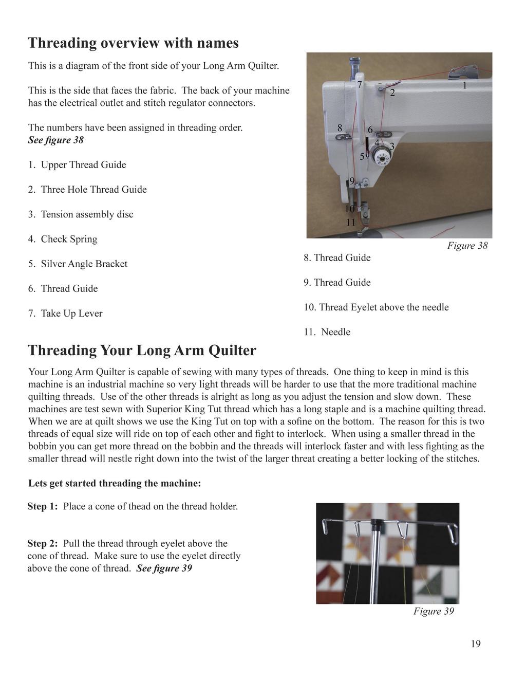

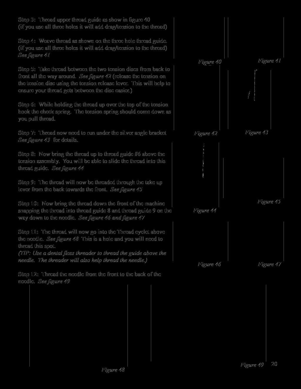
19

20

 has a flat side. The top of the long arm machine needle is round.")
21 How do I change the Needle? A 134RSAN needle (size 18) will be installed on your Long Arm Quilter from the factory. When it is time to replace the needle you can easily install one. Be sure the power switch is off on the machine. Remove the bobbin case. To remove the needle use the smaller screwdriver included with your machine. Top of needle is round. No flat like on your home needles Step 1: Loosen the screw just above the thread guide on the needle bar; the needle should fall out as you loosen the screw. Long groove goes to the front. This is a path for the thread to follow Look closely at the needle. Your home sewing machine needle shank (top of the needle) has a flat side. The top of the long arm machine needle is round. On the point end of the needle there is a scarf, or notch, in one side. The scarf must face the back of your machine. The long groove at the eye of the needle faces you as you insert the needle. Back of needle has a scarf. This is where the hook passes and picks up the top thread to create the stitch. Figure 50 Why does the scarf go to the back of the machine? When the needle goes down through the fabric into the bobbin case, the hook comes around behind the needle to pick up the thread. The scarf has to be there to provide a way for the hook to get between the needle and the thread in order to pick up the thread. Step 2: Place the new needle up in the slot, making sure the needle is up in the needle bar as far up as it will go. Make sure the scarf is facing the back of your machine. Tighten the screw on the needle bar while holding the needle up. TIP: Use the old needle to hold the new needle in place while you tighten the screw. By placing the point of the old needle into the eye of the new needle you can see how straight you are placing the scarf of the needle. Before you turn your machine on go to the back of the machine and turn the hand wheel a complete turn making sure the needle goes down in the center of the throat plate and the hook in the bobbin area rotates with the needle smoothly. Put the needle down as far as possible. In the bobbin area, you should be able to see you the eye of the needle. When the hook rotates it picks up the thread at the back of the needle then the top thread pulls the bobbin thread up to create a stitch. The scarf must face the back of your machine. 21
22 How do I make adjustments to make the perfect stitch? Understanding how your long arm machine makes a stitch will help you make the proper adjustments to make the perfect stitch. The technique all long arm machines use to make a stitch is basically opposite of the home sewing machine. The home sewing machine is designed to press together two layers of fabric and sew while the fabric is held in place by the presser foot. Long arm machines are designed to press and sew multiple layers together while the machine head is moving. The difference is that there is practically no needle deflection on a standard sewing machine and a large amount of needle deflection on the long arm. The higher the tension, the more the needle will deflect. Another cause for the needle to deflect on a standard machine is the type of fabric being sewn. A tightly woven fabric tends to force the needle in different directions as it penetrates the fabric. This type of deflection depends greatly on the type of needle and type of point you use, such as a ball point or sharp point. Needle deflection, what is needle deflection? What causes needle deflection? How is needle deflection related to the stitches on my quilt? On a long arm quilting machine a stitch is mechanically created the same as a home sewing machine except the quilter is the feeddog moving the machine head over the fabric. The hopping foot presses the fabric together tighter and quicker than a home sewing machine presser foot because the fabric must be able to slide between the foot and the needle plate as the machine is sewing. This means that the machine is moving while the needle is in the fabric. The worst thing for a needle is to be in the fabric while the machine is moving which bends the needle, creating needle deflection. Good stitches will interlock in the batting between the quilt top and backing. In real life, this goal is rarely achieved. For this reason, you need to be aware that you will have pokies if you use different colors of thread on top and in the bobbin. Pokies are where you can see tiny dots of the contrasting thread where the bobbin catches the top thread. If there is slightly more tension on the top than on the bottom, then you will see the pokies on the top side of the quilt. If the greater tension is on the bobbin, then you will see the pokies on the back of the quilt. If the pokies are objectionable to you, use the same color thread on both top and bottom. TIP: A general rule of thumb is that if the stitch looks bad on the top it is the bottom tension. If the stitch looks bad on the bottom it is the upper tension. The upper and lower threads play tug of war with each other. 22
23 Tension, Tension, Tension... This probably causes more problems than anything else. You need correct tension on the top and bottom threads but you also must have correct tension on the quilt held between the bars. You should be able to gently rock the belly bar where the backing fabric is attached. This allows enough movement of your quilt layers for the needle to penetrate and make good stitches. Before you start making adjustments to your machine ask yourself, What changed? If your machine was stitching great and all of a sudden it has loopies on the back or puckers, What changed? Did you just change the bobbin? Did you just lift the take up bar? Did you lower the take up bar after finishing your last quilt? Did you recently change the needle? Did you just roll the quilt? If the take up bar with the quilted portion of your quilt is too high, it will result in poor stitch quality. You need a finger tip space between the quilt and the machine bed. Higher will result in poor stitch quality. Lower and the quilt will create a drag on your machine s movement. Look at your bobbin, a sloppy wound bobbin will not create a good stitch. Make sure that the threads on the bobbin are snug and evenly wound. Check to see if there is a piece of lint in the bobbin case. Tension Trouble shooting checklist Is the side tension lever down? Have I oiled my machine regularly? Is the quilt too tight on the frame? Is the thread coming off the cone freely? Has your thread jumped out of the tension discs? Check your threading. Has anything been missed or has the thread flipped itself around something, increasing your tension? Is the hopping foot too high or too low? Is your take up bar too high? Did you lower the take up bar after your last quilt? Do you need to change your needle? Is your needle in properly? Top Thread Breaking Check to see that your thread is coming off the spool freely. The thread guide is centered over the spool and has not developed any burrs or catches. Check to see if the thread has looped itself around the spool pin. Check to see if the needle is in correctly, with the scarf facing the back of the machine. Have you recently changed the needle? Is it as high as it will go in the needle bar? The Stitch Regulator does not keep up with me? Just like driving your car you need to make controlled starts and stops, practice being consistent in your movements. Eyelashes Eyelashes on the back of the quilt can be caused by too little top tension. Turn the thread tension disk clockwise ¼ turn. Make small adjustments. Repeat until stitch quality is good. Remember the upper and lower thread play tug of war with each other. Loose Top Stitch Is the tension lever handle down? It lowers the hopping foot and applies the tension disk. Is the bobbin thread inserted in the slot of the bobbin case? Adjust the tension disk small turns clock wise. Repeat until stitch quality if good. 23
24 Quilt Top Puckers Is your backing fabric stretched too tight? While the backing fabric needs to lie flat and without wrinkles, stretching it too tight can make the quilt top pucker. After stitching and releasing the backing fabric the top will pucker. The top tension is too tight. Adjust the tension disc small turns counter clockwise. Repeat until stitch quality is good. Stitches are Skipped Skipped stitches leave needle holes without thread while large and small stitches in regulated mode means the encoders are not picking-up the signal of your movements because of lint or thread stopping or slowing the reading. First, check to see that your machine is threaded correctly. Look at the check spring, does the thread lay in the check spring? When properly threaded the check spring will move up and down as the machine is stitching and the thread is flowing freely. Check the needle. Be sure it is all the way up into the shaft and the scarf is toward the back. If it has been used for some time, replace the needle. A blunt needle will make a popping sound as it penetrates the quilt sandwich. Machine Drags Making it Difficult to Move Check to make sure the quilt on the take up bar is not dragging on the bed of the machine. A finger tip distance between the take up bar and the bed of the machine is all that is necessary. Elevating the take up bar too high can cause loopies on the back. Look for lint or thread that might be snagging as you move the machine. Difficult to Control the Movement of the Machine Check for lint or other debris on the track and bars. Sometimes the smallest pieces of thread create the biggest headaches. 24


 Figure 51 Figure")
 Screw")


25 Check spring replacement/tension Knob From time to time you may need to replace the check spring. We will use a series of photos to help you. Broken Spring Tension Assembly with Broken Spring. (old tension knob) Figure 51 Figure 52 Figure 53 Tension Assembly with good spring (new Tension knob) Screw on inside of machine loosen only. DO NOT REMOVE PIN Remove assembly from machine Be careful of release pin Figure 54 Figure 55 Machine with tension assembly removed Figure 56 Tension assembly out of machine DO NOT LOOSE PIN Loosen screw only DO NOT REMOVE Figure 57 Figure 58 Remove tension assembly from barrel Tension assembly, Barrel Figure 59 Figure 60 Figure 61 Figure 62 Remove spring Spring Removal Spring Removed 25


26 Figure 63 New Spring, This tail is what was broken Insert the new spring Figure 64 Figure 65 Twist while inserting the new spring New spring in place Figure 67 Figure 68 Insert the tension assembly back into the barrel. REMEMBER DO NOT LOOSE THE PIN Insure that you are all the way in Figure 69 Figure 70 Give the tension assembly a twist until you feel resistance on the check spring Figure 71 Tighten screw. Make sure the pin is still there. Figure 72 Place the assembly back into your machine Figure 73 Once in ensure that your check spring is at 11:00 Figure 74 Press in and notice the tension disk opens Figure 75 Release and the disk will close; this is the proper place for your tension assembly 26


27 Figure 76 Figure 77 Figure 78 Tighten screw on your machine Tension assembly back in place with new check spring at 11:00 Machine will not sew. I can not turn the hand wheel No matter how hard you try to keep the bobbin area free of loose threads and lint we sometimes with get a jam. Most jams start with the needle down as the jam is because something gets into the bobbin race. The bobbin race is a part of the bobbin hook which keep the hook rotating smoothly and no wandering as it rotates. Don t panic this can be cleared it just sometimes take some work. Step 1: Turn the power off Step 2: Remove the belt guard so that you can get a good grip on the hand wheel. See page 10 for instructions For fine adjustment of check spring insert screwdriver turn clockwise for more tension Normal sew rotation if you are standing at the back of the machine looking at the hand wheel is counter clockwise. If you turn the machine counter clockwise you will force what ever is jamming the machine deeper into the bobbin race. Figure 79 Step 3: Rotate the hand wheel clockwise to back the jam out of the bobbin race. (This may take some work to get it worked free.) See figure 79 Step 4: Normally when you get it backed up it will fall out and you will be able to make a full rotation with the hand wheel. Once it feels free take the needle plate off the machine and give it a good cleaning in the bobbin area. Prior to putting the needle plate back on rotate the hand wheel counter clockwise (normal machine rotation) While rotating the hand wheel by hand ensure that you have free movement of the machine. If everything is working well you can put the needle plate back on and put the belt guard back on, You will be ready to start quilting again. Figure 80 The Race is this small space here on the hook assembly Figure 80 shows thread caught Figure 81 show the race Figure 81 27

. This should be engaged in the notch (B) of the bobbin case holder.")

 This will allow you to raise and lower the needle bar for correct location.")
28 Timing between needle and rotating hook If you need to adjust the timing of the machine follow these steps to help get the proper timing on your machines. Step 1: Remove the two needle plate screws from your machine and set the needle plate to the side Step 2: Remove the two screws on the protection cover at attach it to the face plate of the machine. See figure 82 Step 3: Remove the three screws holding the face plate to the machine. Remove the face plate and set this part aside. Figure 82 Step 4: Check the protection flange of the position bracket (A). This should be engaged in the notch (B) of the bobbin case holder. (D) in the drawing shows the set screw to adjust hook timing. See figure 83 Step 5: Turn the hand wheel to locate the needle to it s lowest position. Note: correct needle position is when you can see a small portion of the eye of the needle. See figure 84 Step 6: If the needle is not stopping in the correct position you will need to proceed to the next step. If it is in the correct position move to step 9 Figure 83 Step 7: Loosen Needle bar connecting screw (A) This will allow you to raise and lower the needle bar for correct location. NOTE: CHECK ALL PHOTOS BEFORE MAKING ANY ADJUSTMENTS See figure 85 Step 8: Once you have the needle in the correct location tighten Needle bar connecting screw (A) to prevent the needle bar from moving out of position. Figure 84 Adjusting rotating hook point timing with needle Step 9: Turn the hand wheel counter clockwise to locate needle to its lowest position. Step 10: At lowest position turn the hand wheel to raise the needle 2.5 mm (1/8 ) See figure 85 Step 11: Hook point should be just above eye of the needle. See figure 87 Figure 85 28

 Figure 86 Step 14: With the hook loose reposition the needle to the lowest position.")

29 Step 12: If the hook point is in the correct position then move to step 18. If the hook point is past this point or not yet reached this position then you will need to follow the next few steps to adjust the hook so that when the hook point reaches this position it is just above the eye of the needle. Proceed to the next step. Step 13: Refer to drawing 31 see figure 83 for position of the three screws (D). Loosen the three screws holding the hook assembly to the shaft. (Note you will have to rotate the hand wheel to get to all three screws.) Figure 86 Step 14: With the hook loose reposition the needle to the lowest position. Rotate the hand wheel counter clockwise to bring the needle up 2.5mm (1/8 ) see figure 86 Step 15: Now rotate the hook so that the point of the hook is just at the edge of the needle. See figure 87 Figure 87 Step 16: Lock one screw holding the hook into this position. Step 17: Rock the hand wheel back and forth to ensure that you have the hook in the right position to pass the back of the needle just above the eye of the needle. Step 18: When adjusting the rotating hook point timing also note that clearance between notch bottom of needle D and hook point C must be maintained. HOOK CAN NOT RUB AGAINST NEEDLE. Step 19: Once you feel like everything is in the right place tighten all screws you loosened. Figure 88 Step 20: Return all covers and screws back into place on your machine. 29
 in place.")
 to prevent Bobbin")
 so that you can adjust the tension assembly thread guides (E).")
30 Adjusting the bobbin winder lever (amount of fill on the bobbin) Step 1: Using your allen wrench loosen the set screw (A) holding the Bobbin winder Lever (B) in place. See figure 89 and 90 Note you do not need to pull the bobbin winder out to adjust this setting. Step 2: Move the Bobbin winder lever in for less fill and out for more fill Step 3: Tighten set screw (A) to prevent Bobbin winder lever (B) from moving Figure 89 Adjusting the tension assembly thread guides for proper fill. Figure 90 Step 1: Loosen the set screw (D) so that you can adjust the tension assembly thread guides (E). Adjust tension assembly thread guides (E) up and down until bobbin fills evenly top to bottom. See figure 91 Step 2: Tighten the set screw. Figure 91 30
 to the right for more contact with the inner shaft or mover left for less contact.")

31 Adjusting bobbin winder and contact with the shaft Step 1: Loosen the three (3) screws (A) holding the bobbin winder in place but do not remove them. See figure 92 Step 2: Twist the bobbin winder (B) to the right for more contact with the inner shaft or mover left for less contact. Note: When twisting the bobbin winder (B) you need to stand on the side of the machine with the access panel Step 3: The bobbin winder disk with the friction ring needs to contact the disk on the upper shaft when engaged. See figure 93 Step 4: Once done moving the bobbin winder retighten the screws to hold the bobbin winder in place. Figure 92 Friction Ring Turning the bobbin winder to the right will move the friction wheel closer Turning the bobbin winder to the left will move the friction wheel away Figure 93 31


32 Attaching the Rear Handle Bars The following instructions will help you install the rear handle bars to your Long Arm Quilter Step 1: Locate your rear handles. See figure 94 Step 2: These handles are going to connect to the handle bar block on the back of the machine below the belt guard on the base of the machine. See figure 95 Step 3: Remove the two screws holding the outer block on the machine. Step 4: Position the handle bar in the space provided and reattach the outer block and the two screws. Step 5: Before securing the handle bar, position the handle bar so that you are able to use them and they will not hit anything as you move the machine along the frame. Step 6: Connecting the cables. You should have two short RJ50 cables with the rear handle set. Step 7: Connect one short RJ50 cable to the middle port on the left handle bar controller. The other end of the cable will connect to the thumb controller on the right handle bar. On the thumb controller on the right handle bar are two ports. The RJ50 from the left handle bar needs to plug into the left connector on this thumb controller. Step 8: Connect the other short RJ50 cable to the port on the left side of the left controller. Now the other side of this RJ50 cable will connect to the top port on the back of the white box where the power cord plugs in. Step 9: The RJ50 cable which is hanging out of the bottom of the white box where the power cord plugs in will be plugged into the right port on the left handle bar controller. When you have all the cables connected to the LCD controller on the rear handles left side all the ports will have a cable connected. The left port cable will connect to the large RJ50 port on the white box. The center port will connect to the left port on the right handle bar thumb control. The right port will connect to the cable which was hanging out of the bottom of the white box. figure 94 figure 95 Short RJ50 Cable From left port on the left hand controller to the upper connector on the white box. Short RJ50 Cable From center port to Thumb controller on the right RJ50 Cable From bottom of white box to the right connector on the left controller 32
Owner s Manual For Sit Down
 Owner s Manual For Sit Down Feb 2015 Table of Contents Warranty...3 Your Light Fixture...4 Attaching the Belt Guard...4 Your Thread Stand...5 Control panel...6 Needle position...7 Speed Setting...8 What
Table of Contents. Warranty...3. Attaching your square tubing...4. Your Light Fixture...5. Your Thread Stand...6. Attaching your Laser Light...
 Owner s Manual Table of Contents Warranty...3 Attaching your square tubing...4 Your Light Fixture...5 Your Thread Stand...6 Attaching your Laser Light...7 What is the Tension Release Lever?...7 Needle
Owner s Manual For Sit Down
 Owner s Manual For Sit Down Table of Contents Warranty...3 Attaching your square tubing...4 Your Light Fixture...5 Your Thread Stand...6 What is the Tension Release Lever?...7 How Do I Adjust the Height
Long arm Quilting Machine
 Long arm Quilting Machine 2014 Printed in the United States First Print Table of Contents Warranty...6 Diagram showing the sides of the machine...7 Attaching the Handlebars... 8 Attaching Rocker Arm Cover...
Table of Contents. Placing your machine on the carriage...3. Remove the packing attached to your machine...3. Light Fixture...4. Your Thread Stand...
 Owner s Manual Table of Contents Placing your machine on the carriage...3 Remove the packing attached to your machine...3 Light Fixture...4 Your Thread Stand...5 Belt guard...6 Attaching your handle bars
Welcome...3. Warranty...4. Attaching your Thread Stand...5. Attaching your Lamp...6
 OWNERS MANUAL Table of Contents Welcome....3 Warranty....4 Attaching your Thread Stand....5 Attaching your Lamp....6 Connecting your Ansley to your Carriage and Controls on the Handles....7 What is the
Table of Contents. Welcome...5. Warranty...6. Diagram showing the sides of the machine...7. Attaching the Handlebars Your Rocker Arm Cover...
 2015 Printed in the United States First Print September 2015 Table of Contents Welcome...5 Warranty...6 Diagram showing the sides of the machine...7 Attaching the Handlebars... 8 Your Rocker Arm Cover...
User Guide.
 User Guide www.tinlizzie18.com Table of Contents Welcome 5 Warranty 6 Diagram showing the sides of the machine 7 Attaching the Handlebars 8 Your Rocker Arm Cover 9 Your Rear Handlebars 9 Your Thread Stand
TIPS & TROUBLESHOOTING
 Achieving good stitch quality 5450 North W Street Pensacola FL 32505 850-433-1414 www.martellinotions.com TIPS & TROUBLESHOOTING Understanding how your long arm machine makes a stitch will help you make
SAFETY MAINTENANCE THE LONG ARM MACHINE
 SAFETY MAINTENANCE THE LONG ARM MACHINE Quilting Machine Usage Guidelines All general safety guidelines apply to this piece of equipment Befoaoe Use: Use only attachments recommended by the manufacturer
SERVICE MANUAL AND PARTSLIST
 SERVICE MANUAL AND PARTSLIST Next 20 CONTENTS WHAT TO DO WHEN... 1~3 SERVICE ACCESS FACE COVER... 4 TOP COVER... 4 BASE COVER... 5 REAR COVER... 6 FRONT COVER... 7 MECHANICAL ADJUSTMENT NEEDLE THREAD TENSION...
SERVICE MANUAL PARTS LIST MODEL: NH40
 SERVICE MANUAL & PARTS LIST MODEL: NH40 CONTENTS What to do when... 1-3 SERVICE ACCESS Face Cover... 4 Bed Cover... 5 Free-arm Cover... 6 Front Cover... 7 Rear Cover... 8 MECHANICAL ADJUSTMENT Presser
Copyright December 17, 2018 Grace Company (Reproduction Prohibited) Version 3.4
 Version 3.4") Copyright December 17, 2018 Grace Company (Reproduction Prohibited) Version 3.4 IMPORTANT SAFETY INSTRUCTIONS When using an electrical machine, basic safety precautions should always be followed, including
Copyright December 17, 2018 Grace Company (Reproduction Prohibited) Version 3.4 IMPORTANT SAFETY INSTRUCTIONS When using an electrical machine, basic safety precautions should always be followed, including
Q-Zone Hoop-Frame. Assembly Instructions. Copyright July 11, 2018 Grace Company (Reproduction Prohibited) Version 1.8
 Version 1.8") Q-Zone Hoop-Frame Assembly Instructions Copyright July 11, 2018 Grace Company (Reproduction Prohibited) Version 1.8 Table of Contents Table of Contents... i Warranty... ii Parts List Box 1...iii Box 2...
Q-Zone Hoop-Frame Assembly Instructions Copyright July 11, 2018 Grace Company (Reproduction Prohibited) Version 1.8 Table of Contents Table of Contents... i Warranty... ii Parts List Box 1...iii Box 2...
Top Innovations, Inc. Innovative Products to Make Your Life Easier. Model SP-402 Owner s Manual
 Top Innovations, Inc. Innovative Products to Make Your Life Easier Model SP-402 Owner s Manual THIS IS NOT A TOY! Adult supervision recommended Item contains sharp functional points and small parts Machine
Basic steps to time the Gammill quilting machine s rotary sewing hook
 Basic steps to time the Gammill quilting machine s rotary sewing hook 1.) Turn the machine off and unplug it. 2.) With the needle bar in the raised position, remove the bobbin and bobbin case. 3.) Remove
This guide contains everything you need to set up and operate all three. Inspira Imperial Quilting Frame Assembly...2
 Congratulations on the purchase of your Husqvarna Viking Mega Quilter 18x8, Inspira Imperial Quilting Frame, and QBOT by Inspira! This guide contains everything you need to set up and operate all three.
Continuum Frame Assembly Instructions
 Continuum Frame Assembly Instructions Copyright January 1, 2017 Jim M. Bagley, GraceWood, Inc (Reproduction Prohibited) Version 2.2 Table of Contents Continuum Frame Table of Contents... i Warranty...ii
SERVICING MANUAL 419S/423S
 SERVICING MANUAL 415 419S/423S TROUBLESHOOTING PROBLEM CAUSE REMEDY REFERENCE 1. SKIPPING 1. NEEDLE IS NOT INSERTED INSERT THE NEEDLE PROPERLY. STITCHES PROPERLY. 2. NEEDLE IS BENT OR WORN. CHANGE THE
SERVICE MANUAL MODEL: 13512, 14412, 15312
 SERVICE MANUAL MODEL: 13512, 14412, 15312 CONTENTS TROUBLESHOOTING... 1-3 SERVICE ACCESS (1) FACE COVER, BELT COVER... 4 SERVICE ACCESS (2) BASE PLATE... 5 SERVICE ACCESS (3) FRONT COVER... 6 SERVICE ACCESS
Electric Skein Winder
 Electric Skein Winder Assembly and Use Package Contents 1 - Triangular Body (w/ motor) 1 - Cross Arm 1 - Left Foot (w/ yarn guide) 1 - Right Foot 1 - Adjustable Finger (w/ yarn clip) 3 - Adjustable Fingers
Timing the Millennium, Freedom, Liberty and Discovery
 Timing the Millennium, Freedom, Liberty and Discovery Use these instructions in conjunction with your instructional CD. Symptoms: Skipping or missing stitches. Solution: Change needle. (We strongly recommend
CONTENTS. LOCATE AND IDENTIFYTHE PARTS... WlNDTHE BOBBIN... PREPARE YOUR TOP THREAD... WHAT TO DO WH EN...
 SERVICE MANUAL SEWING MACHINE MODEL 385.11206300 MARCH, 2003 CONTENTS LOCATE AND IDENTIFYTHE PARTS... WlNDTHE BOBBIN... PREPARE YOUR TOP THREAD... WHAT TO DO WH EN... 1 2 3 4-6 SERVICE ACCESS FACE COVER...
STOP! READ THIS FIRST
 STOP! READ THIS FIRST Page 1 of 37 Getting Started With Your Pantograms GS1501 Embroidery Machine (the quick guide) Thank you for choosing Pantograms for your embroidery system provider. We encourage you
MAIN PARTS
 MAIN PARTS 7 8 9 10 11 12 13 1 2 3 17 4 5 6 01 02 03 04 05 12 23 34 45 56 13 24 35 46 57 14 25 36 47 58 15 16 26 27 37 38 48 49 59 60 06 07 08 09 10 17 18 28 29 39 40 50 51 61 62 19 30 41 52 63 20 21 31
The Queen Quilter Professional Quilters Kit Frame
 The Queen Quilter Professional Quilters Kit Frame Assembly Instructions Table of Contents: Before you begin......................... Pg. 2 Wood parts............................. Pg. 3 Hardware..............................
CONTENTS LOCATE AND IDENTIFY THE PARTS... WIND THE BOBBIN... PREPARE YOUR TOP THREAD... STITCH SELECTOR / STITCH LENGTH/STITCH WIDTH CONTROLS...
 SERVICE MANUAL SEWING MACHINE MODEL 385. 15208400 OCTOBER, 2003 CONTENTS LOCATE AND IDENTIFY THE PARTS... WIND THE BOBBIN... PREPARE YOUR TOP THREAD... STITCH SELECTOR / STITCH LENGTH/STITCH WIDTH CONTROLS...
Understanding the Controls
 Understanding the Controls Your new Millennium or Freedom SR machine uses simple controls and has handy features to make your quilting more fun and enjoyable. The charts below give you a quick overview
NAMES OF PARTS. 1 Thread guide for bobbin winding 2 Take-up lever. 3 Upper thread tension dial. 4 Face cover. 5 Thread guide for upper threading
 6 Presser foot thumb screw 9 Spool pins (retractable) 8 Shuttle cover 5 Thread guide for upper threading 7 Presser foot 4 Face cover NAMES OF PARTS.r4r : VjN S* ;WWE7-17 16 15 MODEL 860.-.-.- --. :.---.-
SEWING MACHINE MODEL 385, 15358
 SERVICE MANUAL SEWING MACHINE MODEL 385, 15358 BER, 2006 CONTENTS LOCATE AND identify THE PARTS... WiND THE BOBBIN... PREPAREYOURTOPTHREAD... WHAT TO DO WHEN... 1 2 3 4-6 SERVICE ACCESS FACE COVER... BELT
Sewing Machine 911 with Claudia Miller
 Sewing Machine 9 JAMMED MACHINE MACHINE IS NOT STITCHING Threads are too long and get caught in the bobbin holder Machine is dirty Bobbin thread was not drawn up through the machine Threads are stuck when
Juki Quilting Frame. Assembly and Use Instruction Manual. Max Overall Dimensions: Length Crib: King: Tall: Wide: 42
 Juki Quilting Frame Assembly and Use Instruction Manual Max Overall Dimensions: Length Crib: 63 1 4 King: 128 1 4 Tall: 45 3 4-51 3 4 Wide: 42 Copyright January, 2015 Version 9.6 (Page 1) Contents Parts
Depending on the size you ordered you will have either 5 Foot sections which will build the 10 Foot frame or 6 Foot sections which will build the 12
 XL Quilting Frame 1 Depending on the size you ordered you will have either 5 Foot sections which will build the 10 Foot frame or 6 Foot sections which will build the 12 Foot frame Printed 2 June 2014 Updated
To register your machine warranty and receive Baby Lock product updates and offers, go to If you have questions with
 To register your machine warranty and receive Baby Lock product updates and offers, go to www.babylock.com/profile. If you have questions with registration, visit your Authorized Baby Lock Retailer. CONTENTS
FBX1104P FBX1104 FBX1106P FBX1106
 FBX1104P FBX1104 FBX1106P FBX1106 Second edition : September 2004 No. 040037 INTRODUCTION Thank you for your purchasing Kansai Special's FBX Series. Read and study this instruction manual carefully before
STOP! READ THIS FIRST
 STOP! READ THIS FIRST 1 Getting Started With Your Meistergram Embroidery System (the quick guide) Thank you for choosing Pantograms for your embroidery system provider. We encourage you to read the following
The Phoenix. Professional Quilting Frame. Copyright January 1, 2016 Jim M. Bagley, GraceWood, Inc (Reproduction Prohibited) Version 2.
 Version 2.") The Phoenix Professional Quilting Frame Copyright January 1, 2016 Jim M. Bagley, GraceWood, Inc (Reproduction Prohibited) Version 2.1 1 The Phoenix Professional Quilting Frame Parts List Box 1...3 Box
The Phoenix Professional Quilting Frame Copyright January 1, 2016 Jim M. Bagley, GraceWood, Inc (Reproduction Prohibited) Version 2.1 1 The Phoenix Professional Quilting Frame Parts List Box 1...3 Box
Brother Industries, Ltd. Nagoya, Japan
 4. 2001. This service manual has been compiled for explaining repair procedures of the MODEL XL-6562, XL6452, XR- 46. This was produced based on up-to-date product specifications at the time of issue,
S-85SCH
 4411-4423-4432-4443-4452 5511-5523-5532-5554 44S-85SCH Service Manual 104 73 14-26 2014-02-24 CONTENTS 1. Names of principal parts...2 2. Removing methods of external parts 2-1 Sewing table...3 2-2 Face
CAUTION- SAVE THESE INSTRUCTIONS This product is for household use, or equivalent.
 Never operate this sewing machine if it has a damaged cord or plug, if it is not working properly, if it has been dropped or damaged, dropped into water. Return this sewing machine to the nearest authorized
ABM International, Inc.
 ABM International, Inc. Lightning Stitch required 1 1.0: Parts List head and motor assembly (Qty. 1) Reel stand (Qty. 1) Needle bar frame clamp (Qty. 1) Motor drive (Qty. 1) 2 Cable harness with bracket
ABM International, Inc. Navigator Assembly Manual
 ABM International, Inc. 1 1.0: Parts List Tablet (Qty. 1) Tablet mount (Qty. 1) NOTE: Mount may appear and operate different then image below Control Box (Qty. 1) Motor Power Supply (Qty. 1) 2 X-axis motor
Using the RhAT II Universal
 Using the RhAT II Universal To use the Original RhAT Tools, the main shaft of the machine had to be rotated to the setting position, either mechanically or electronically, while the needle bar was disengaged
HOW TO USE YOUR LONG SHUTTLE MANUAL SEWING MACHINE. 4çJ MODEL NO.768
 NO.768 MODEL 4çJ Ii SEWING MACHINE LONG SHUTTLE MANUAL HOW TO USE YOUR INDEX Zigzag Formation 18 Zigzag Sewing And Pattern Formation 17 Turning a Corner 14 Placement of Needle 4 Picking Up Bobbin Thread
The Mini Pinni Quilting Frame
 The Mini Pinni Quilting Frame Copyright September 2007 Jim M. Bagley, GraceWood, Inc (Reproduction Prohibited) Print Date 10-16-07 1 The Mini Pinni Quilting Frame By The Grace Company Part List Parts List
Replacing the Reciprocator on an SWF Multi-head.
 Replacing the Reciprocator on an SWF Multi-head. Follow the instructions below to replace the reciprocator in the SWF multi-head machines. The tools required are found in the tool kit that came with the
CONTENTS PRECAUTIONS BEFORE STARTING OPERATION PREPARATION FOR OPERATION CAUTIONS ON USE OPERATION
 CONTENTS PRECAUTIONS BEFORE STARTING OPERATION ------------------------------------- 1 PREPARATION FOR OPERATION 1. Adjustment of needle bar stop position ---------------------------------------------------------
WX8800 WX8700 LX5801 WX8842 WX MC30
 WX8800 WX8700 LX5801 WX8842 WX8842-1 MC30 First published : August 1991 Third edition : August 2004 No. 040037 INTRODUCTION Thank you for your purchasing Kansai Special's WX Series. Read and study this
MACHINE QUILTING FRAME
 MACHINE QUILTING FRAME YOU WILL NEED TO PURCHASE: 5 pieces of 1-1/4 thin wall metal conduit (EMT) cut to your preferred length for the rollers. (Maximum 120 ) DETERMINING YOUR ROLLER LENGTH: Determine
PARTS LIST MODEL: HDEJ1800
 First Edition: June 0 PARTS LIST 0 8 4 8 8 4 8 0 KEY PARTS NO. NO. DESCRIPTION 0400 Top cover (unit) 00 Top cover (unit) 0000 Top cover 4 40A04 Flip-top sewing instruction panel 000 Hinge rod (right) 00
FBX-PA-2AC. Third edition : April No
 FBX-PA-2AC Third edition : April 2006 No. 060058 INTRODUCTION Thank you very much for purchasing Kansai Special FBX series. Read and study this Instruction Manual carefully before you start any of the
Intro to the Sewing Machine
 Intro to the Sewing Machine 1. Bobbin Cover Opens to allow you to put the bobbin and bobbin case in the machine. 2. Stitch Plate Where the seam allowance guidelines are found. Each line is 1/8 apart, beginning
Service Manual for XLE/XLT Series Laser Engravers
 Service Manual for XLE/XLT Series Laser Engravers Table of Contents Maintenance...1 Beam alignment...3 Auto focus alignment...8 Bridge alignment...10 Electronics panel replacement...11 X motor change...12
Symbols used. Move the part in the direction of the arrow. Set the clearance as indicated. Move the part to its highest or lowest position.
 4.1999. This service manual was compiled for use when repairing the XL5300, 5200, 5100, 5030, 5020, 5010,PX300,200,100 Zigzag Stitch Sewing Machines. Use this manual, together with the Parts Catalog, when
the needle, the user must take sufficient care to avoid injury and observe the sewing area continuously while sewing.
 / - nstruct0fl maflua 7 the needle, the user must take the light bulb is 15 watts. agent. by anyone but an authorized Pfaff D) The drive belt must never be adjusted B) When leaving the machine, chan C)
Removing and Replacing the Y-truck
 Service Documentation Removing and Replacing the Y-truck To remove and replace the Y-truck you will need the following tools: 4mm Allen wrench 12mm stamped flat wrench #2 Phillips screwdriver (magnetic
Replacing the Reciprocator on the SWF Compact Series Machine (601C and 1201C)
") Follow the instructions below to replace the reciprocator in the SWF Compact series machines. The tools required can be found in the tool kit that came with the machine. Preparation 1. First, place the
Follow the instructions below to replace the reciprocator in the SWF Compact series machines. The tools required can be found in the tool kit that came with the machine. Preparation 1. First, place the
16U288 SINGER' SEWING MACHINE. From the library of: Superior I Sewing Machine & Supply LLC INSTRUCTIONS. Form UIO3 (Rev, 377)., THE SINGER COMPANY
., THE SINGER COMPANY") iiv^- Form UIO3 (Rev, 377)., INSTRUCTIONS FOR USING AND ADJUSTING SINGER' SEWING MACHINE 16U288 THE SINGER COMPANY From the library of: Superior I Sewing Machine & Supply LLC CONTENTS PAGE DESCRIPTION
iiv^- Form UIO3 (Rev, 377)., INSTRUCTIONS FOR USING AND ADJUSTING SINGER' SEWING MACHINE 16U288 THE SINGER COMPANY From the library of: Superior I Sewing Machine & Supply LLC CONTENTS PAGE DESCRIPTION
First published : May 1997 Fourth edition : January No
 First published : May 1997 Fourth edition : January 2006 No. 050153 INTRODUCTION Thank you for your purchasing Kansai Special's FX Series. Read and study this instruction manual carefully before beginning
Copyright Jan 01, 2017 Jim M. Bagley, GraceWood, Inc (Reproduction Prohibited) Version 1.0. Sit Down Instruction Manual
 Version 1.0. Sit Down Instruction Manual") Copyright Jan 01, 2017 Jim M. Bagley, GraceWood, Inc (Reproduction Prohibited) Version 1.0 Sit Down Instruction Manual Table of Contents IMPORTANT SAFETY INSTRUCTIONS 3 IMPORTANT SAFETY INSTRUCTIONS 4
Copyright Jan 01, 2017 Jim M. Bagley, GraceWood, Inc (Reproduction Prohibited) Version 1.0 Sit Down Instruction Manual Table of Contents IMPORTANT SAFETY INSTRUCTIONS 3 IMPORTANT SAFETY INSTRUCTIONS 4
Tin Lizzie 18 Assembly Instructions
 Tin Lizzie 18 Assembly Instructions Revision: 07/29/16 Table of Contents Aides 3 Before You Begin 5 Aides 5 Tools 6 Perfect Stitch Parts 2 12 Modify the Machine 12 Prepare Drill Templates 12 Front Display
Safety Section. Quick Facts
 Safety Section This device complies with Part 15 of the FCC Rules. Operation is subject to the following two conditions: (1) this device may not cause harmful interference, and (2) this device must accept
Assembly Instructions. Copyright May 01, 2013 Jim M. Bagley, GraceWood, Inc (Reproduction Prohibited)
") Assembly Instructions Copyright May 01, 2013 Jim M. Bagley, GraceWood, Inc (Reproduction Prohibited) Table of Contents Part List Part List... 3 Assembly Steps Step 1-Foot Assembly... 5 Step 2-Leg Assembly...
Assembly Instructions Copyright May 01, 2013 Jim M. Bagley, GraceWood, Inc (Reproduction Prohibited) Table of Contents Part List Part List... 3 Assembly Steps Step 1-Foot Assembly... 5 Step 2-Leg Assembly...
INTRODUCTION THANK YOU FOR CHOOSING OUR OVERLOCK MACHINE FOR YOUR SAFETY BEFORE YOU USE - 1 -
 INTRODUCTION THANK YOU FOR CHOOSING OUR OVERLOCK MACHINE This overlock machine can stitch dependable seams on all kinds of fabric, both light and heavy, including cotton, wool, rayon, tricot, jersey, and
SERVICE MANUAL FOR HOMELOCK M1034D 2034D 1134DW 1134D
 SERVICE MANUAL FOR HOMELOCK M1034D 2034D 1134DW 1134D 11.2000 2.2012 I HOW TO USE THIS MANUAL... 1 II HOW TO ADJUST... 2 1. Height of needle bar... 2 2. Position of the lowerlooper... 3 3. Timing of the
Hardware and Components:
 Hardware and Components: (A) 4X 5/16 x 1 Carriage Bolt (B) 2X 5/16 x 2-1/4 Carriage Bolt (C) 2X 5/16 x 3-1/4 Hex Bolt (D) 2X 5/16 x 3/4 Hex Bolt (E) 2X 5/16 x 1-1/4 Hex Bolt (F) 5/16 x 2-1/4 Hex Bolt (G)
UK10 UK11. First published: June No.KX03023
 UK10 UK11 First published: June 2003 No.KX03023 INTRODUCTION Thank you for purchasing Kansai Special s UK series machine. Please study this instruction manual carefully before operating the machine. 1.
The Bowflex Revolution XP Home Gym Assembly Instructions. P/N: Rev ( /0 )
") P/N: 001-7057 Rev ( /0 ) The Bowflex Revolution XP Home Gym Assembly Instructions 2 Table of Contents Before You Start... 2 Tools You Will Need / Hardware Contents... 3 Box Contents... 6 Assembling Your
P/N: 001-7057 Rev ( /0 ) The Bowflex Revolution XP Home Gym Assembly Instructions 2 Table of Contents Before You Start... 2 Tools You Will Need / Hardware Contents... 3 Box Contents... 6 Assembling Your
CONTENTS LOCATE AND IDENTIFY THE PARTS... WIND THE BOBBIN... PREPARE YOUR TOP THREAD... STITCH SELECTOR / STITCH LENGTH/STITCH WIDTH CONTROLS...
 SERVICE MANUAL SEWING MACHINE MODEL 385. 15218400 OCTOBER, 2003 CONTENTS LOCATE AND IDENTIFY THE PARTS... WIND THE BOBBIN... PREPARE YOUR TOP THREAD... STITCH SELECTOR / STITCH LENGTH/STITCH WIDTH CONTROLS...
Horizon Memory Craft Quilt Maker New Owner Lesson
 Ordinary Sewing Session: MC15000 Quilt Maker Embroidery Unit Power cord Knee Lift All the accessories that were packed with the machine Optional: Quilting Template for Ruler Work Fabric: Several 6 squares
Dream Fabric Frame Assembly Instructions
 Dream Fabric Frame Assembly Instructions Copyright January 1, 2016 Jim M. Bagley, GraceWood, Inc (Reproduction Prohibited) Version 2.4 Table Of Contents Parts List 3 Step 1: Table Set Up 6 Step 2: Install
JD-12. Instruction & Parts Manual
 JD-12 Instruction & Parts Manual Framon Manufacturing Company, Inc. 909 W Washington Avenue Alpena, MI 49707 Phone: 989-354-5623 Fax: 989-354-4238 E-mail: support@framon.com Website: www.framon.com The
Side Winder R o u t e r L i f t.
 Woodpeckers PRECISION WOODWORKING TOOLS Side Winder R o u t e r L i f t. INSTALLATION INSTRUCTIONS The wrench handle must be pointing left in order to fully insert or remove it. Lift Wrench Once fully
INSTRUCTION. Industrial Sewing Machines V7100/D,DE,F,ML W8100/D,DE,F,C W8042 W V7002-1S W8103-1S. No Third edition : March 2001
 INSTRUCTION Industrial Sewing Machines V7100/D,DE,F,ML W8100/D,DE,F,C W8042 W8042-1 V7002-1S W8103-1S Third edition : March 2001 No. 010012 INTRODUCTION Thank you for your purchasing Kansai Special's V.W
Inspira Quilt Frame and Mega Quilter FAQ s
 Inspira Quilt Frame and Mega Quilter FAQ s Mega Quilter: What is the Mega Quilter? The Husqvarna Viking Mega Quilter is a semi-industrial sewing machine designed for the home sewer and quilter and the
Dream Fabric Frame Assembly Instructions
 Dream Fabric Frame Assembly Instructions Copyright May 01, 2015 Jim M. Bagley, GraceWood, Inc (Reproduction Prohibited) Version 1 Table Of Contents Parts List 3 Step 1: Table Set Up 6 Step 2: Install the
INSTALLATION LS MODEL
 INSTALLATION LS MODEL Page 2 TABLE OF CONTENTS Section 1: Included parts... pg 4 Section 2: Installing the Shirley Stitcher II on Quilt Frame.. pg 5 Section 3: Connecting Shirley Stitcher II to Tin Lizzie
Motorized or Crank Operated Fortress Zipper Track Shade with Housing and Side Track Installation Instructions
 Motorized or Crank Operated Fortress Zipper Track Shade with Housing and Side Track Installation Instructions Tools Needed Drill 3/8 Metal Drill Bit ¼ Masonry Drill Bit Measuring Tape Pencil 4 Level Phillips
Chapter 4: Troubleshooting and Maintenance
 Training: HAPPY HCD-1501 Operations & Maintenance Chapter 4: Troubleshooting and Maintenance Basic Troubleshooting/ Sewing Interruptions Troubleshooting thread breaks 2 Maintenance and Upkeep Oiling: daily
Daily Maintenance. 2. Insert bobbin cases in to rotary hooks. Make sure bobbin thread is not over 2 inches long. Close bobbin case covers.
 Rotary hook 1. Open bobbin case covers and remove bobbin cases. Use brush to remove lint build up in and around rotary hooks. Compressed air may also be used. Daily Maintenance Cle aning Oiling Rotary
SEWING MACHINE - SINGLE NEEDLE
 SEWING MACHINE - SINGLE NEEDLE 03914 ASSEMBLY AND OPERATING INSTRUCTIONS 3491 Mission Oaks Blvd., Camarillo, CA 93011 Visit our Web site at http://www.harborfreight.com Copyright 2003 by Harbor Freight
Kromski Interlude. Assembly Instructions
 Kromski Interlude Assembly Instructions Important Notice If you have any difficulty in understanding these instructions, assembling the wheel, or having it operate to its fullest potential, WE WANT YOU
30DC Speed Lathe Manual
 30DC Speed Lathe Manual The Crozier Model 30DC Speed Lathe is our most popular model. It has many standard features not found on any other machine in its class or price range. Standard Features 3/4 HP
INSTRUCTION BX1425P,PSM,PTV BX1433P,PSM,PTV BX1025P,PSM BX1033P,PSM. No First published : November 1997
 INSTRUCTION Industrial Sewing Machines BX1425P,PSM,PTV BX1433P,PSM,PTV BX1025P,PSM BX1033P,PSM First published : November 1997 No. 970112 INTRODUCTION Thank you for your purchasing Kansai Special's BX
SEWING MACHINE For use with Janome HD 1000
 SEWING MACHINE For use with Janome HD 1000 YALE CENTER FOR ENGINEERING INNOVATION AND DESIGN Table of Contents p. 3-5... Winding the Bobbin p. 6-7... Threading the Bobbin p. 8-10... Threading the Needle
SINGER 591D200A 591D240A 591D303A 591D305A 591C308A. rom the library of: Superior Sewing Machine & Supply LLC 591D300A
 SINGER 591D200A 591D240A 591D300A 591D303A 591D305A 591D308A 591C200A 591C240A 591C300A 591C308A CONTENTS Page Introducingtlie NewSINGER* Sewing Machine Model 591 \ Oiling the Machine 2 Oiling the Puller
SERVICE MANUAL & PARTS LIST MODEL: MC400E
 First Edition: February SERVICE MANUAL & PARTS LIST MODEL: MC00E PARTS LIST MODEL: MC00E 0 0 MODEL: MC00E KEY PARTS NO. NO. DESCRIPTION 0 0 0B0 000 0A0 0A0 000 000 0 000 0 0000 0000 000 00 0 0 00 A0 0B0
Hardware and Components:
 Hardware and Components: (A) 5/16 x 2 Hex Bolt (B) 5/16 x 2-1/4 Hex Bolt (C) 5/16 x 2-1/2 Hex Bolt (D) 4X 5/16 x 3/4 Hex Bolt (E) 4X 5/16 x 1-1/4 Hex Bolt (F) 11X 5/16 Flat Washer (G) 12X 5/16 Nylock Nut
OPERATING INSTRUCTIONS 3421UX VETERANS BLVD, CARLSTADT, NJ 07072
 OPERATING INSTRUCTIONS 3421UX5-1 400 VETERANS BLVD, CARLSTADT, NJ 07072 CONTENTS DESCRIPTION... 3 OPERATOR INFORMATION... 5-8 INSTALLATION...... 4 ADJUSTMENT... 8-17 LUBRICATION... 5 INDEX Description
INSTRUCTIONS and PARTS BOOK. U. S. Blind Stitch Machines
 r- INSTRUCTIONS and PARTS BOOK for U. S. Blind Stitch Machines Model 88-R. S. BLIND STITCH MACHINE CORP. 12 SEVENTH AVENUE NEW YORK 1, N. Y. LAclcawanna 4-9144-5-6 A SUPPLEMENT TO PARTS CATALOGUE FOR U.S.
USER MANUAL QM30270, version 2.0
 USER MANUAL QM30270, version 2.0 04/18/14 2014 Handi Quilter, Inc. Table of Contents 4 Safety Section Quick Facts 5 Components (Front Side View) 6 Components (Back Side View) 7 Components (Rear and Front
INSTRUCTION MANUAL C240
 INSTRUCTION MANUAL C240 This household sewing machine is designed to comply with IEC/EN 60335-2-28 and UL1594. IMPORTANT SAFETY INSTRUCTIONS When using an electrical appliance, basic safety precautions
pô1e -/C INSTRUCTION MANUAL FOR SEWING MACHINE WHITE
 pô1e -/C -- INSTRUCTION MANUAL I FOR SEWING MACHINE WHITE Retain these numbers for future reference. Model No. Serial No. The Model No. is located on Rating Plate. The Serial No. is located on Bed Plate.
S10C. Instructions. Version S10C-V1c
 S10C Instructions Version S10C-V1c To celebrate our fortieth anniversary, we have transformed the spinning wheel it all started with: the S10. The new S10 Concept spinning wheel makes it possible to customize
Be sure to oil your machine as instructed below. To avoid spotting on garments being embroidered, oil the machine sparingly.
 OILING THE MACHINE Oiling is important for maintaining the machine performance over an extended period of time. Turn the power off when lubricating the embroidery machine. Be sure to oil your machine as
Operation Manual for the EP 1 embroidery peripheral
 Operation Manual for the EP 1 embroidery peripheral Single head, single needle Easy to operate Low power consumption High quality results Part Number 110264-01, Revision A A Saurer Group Company 1575 West
Avanté USER MANUAL. QM30235, version /18/ Handi Quilter, Inc.
 18 Avanté USER MANUAL QM30235, version 2.0 04/18/14 2014 Handi Quilter, Inc. Congratulations on your purchase of the HQ 18 Avanté from Handi Quilter! You haven t just purchased a quilting machine, you
С 800 CASSIDA C 800 HIGH SPEED COIN COUNTER
 С 800 CASSIDA C 800 HIGH SPEED COIN COUNTER This manual contains important information on safety measures and operational features. Please read it carefully before operating your coin counter, and keep
SUNDSTITCH INSTRUCTION BOOK SEWING MACHINES REX TRADING CORPORATION MODELS PB. Z78 15th AVENUE, NEWARK, N. J.
 SEWING MACHINES Area Code 201 242-8485 Cable Address REX - NEWARK, N. J. Z78 15th AVENUE, NEWARK, N. J. 07103 REX TRADING CORPORATION 4$4 101-1 101-2 101-3 101-1 PB MODELS BOOK INSTRUCTION SUNDSTITCH RE
CONTENTS LOCATE AND IDENTIFY THE PARTS... 1 WHAT TO DO WHEN THREADING OF MACHINE
 SERVICE MANUAL SEWING MACHINE MODEL 385.16221300 JULY, 2003 CONTENTS LOCATE AND IDENTIFY THE PARTS... 1 WHAT TO DO WHEN... 2-4 THREADING OF MACHINE...... 5-6 SERVICEACCESS FACE COVER... 7 TOP COVER...