Welcome...3. Warranty...4. Attaching your Thread Stand...5. Attaching your Lamp...6
|
|
|
- Verity Cummings
- 6 years ago
- Views:
Transcription


1 OWNERS MANUAL
2 Table of Contents Welcome....3 Warranty....4 Attaching your Thread Stand....5 Attaching your Lamp....6 Connecting your Ansley to your Carriage and Controls on the Handles....7 What is the Tension Release Lever? 9 How Do I Adjust the Height of the Hopping Foot....9 Adjusting the Walk of the Machine Routine Cleaning and Oiling Bobbin Winder and Bobbins The Control Unit Threading...17 How Do I Change the Needle? How Do I Make Adjustments to Make the Perfect Stitch Tension, Tension, Tension Check Spring Replacement Timing PAgE 2
3 Dear Ansley owner, Welcome to the FLOYD SEWING MACHINE family. Since 1948, Bill Floyd has been designing and improving industrial sewing machines. The Ansley is one of many specialty sewing machines that he has been instrumental in designing and manufacturing. Now, he is passing down the knowledge, passion and tradition to his son Ernie. Together they are co-owners of TinLizzie18, LLC Ernie has been in the sewing industry since In 2005 their shared vision of an affordable long arm quilting machine for the home quilter became reality. Today the TinLizzie18 is in homes all over the world. The Ansley comes with a one year complete warranty. We will always stand behind our product and any warranty issues will be fixed at no charge. Our warranty on parts is five years and covers the sewing machine head, motor, electronics and frame. Customer satisfaction is our number one goal. If you are not happy then we are not happy. Our dealers are selectively chosen, using our criteria of customer service and professional integrity. Enjoy your Ansley26! Sincerely, William Floyd Ernie Floyd PAgE 3

4 Warranty We believe that we have designed and are manufacturing the best longarm quilting machine available. As you unpack your machine be sure to keep the box and packing materials designed to protect the machine during shipping. Should it become necessary for you to return the machine for warranty work please call us for specific instructions for packing and shipping your machine. Your Ansley has a full labor warranty for one year from the day you receive your machine. We guarantee the machine parts for five years. The machine must be cleaned and oiled regularly according to the instructions in this manual. Failure to properly maintain the machine will void this warranty. Your Ansley must be plugged into a surge protected electrical outlet. We highly recommend using an Uninterrupted Power Supply (UPS) also known as a Battery Backup. This helps to ensure that you are getting a regulated 110 volts into your machine. See photo below of UPS Battery Backup. Should we mutually decide that your machine cannot be repaired using normal communications we will arrange for call tags to be sent to you for pick up of the machine. How to Contact Us Should you have a problem with your machine, first call the dealer that sold the machine to you. If for some reason your dealer is unable to resolve your concern, please call (888) This is a photo of the battery backup. Using this will provide you with the best protection. PAgE 4


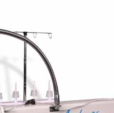
5 Attaching your Thread Stand Ansley comes with a four spool thread stand which attaches to the left side of the machine. This four spool thread stand has a telescoping thread guide which needs to be raised to it s highest position when quilting. On the left side of the machine (when looking from the needle) you will see two screws which hold the thread stand to the machine. Once you have your thread stand attached to the side of the machine then you can attach the thread tree into the holder on the thread stand. Simply place the threaded end of the tree into the hole provided and twist into place PAgE 5

 3. Replace the washer and the nut. 4. Tighten the nut so that the lamp stays in place. 5.")
6 Attaching your Lamp Ansley comes with a flexible lamp which helps to light your work area. This lamp is shipped with a light bulb and there is a plug that will need to be attached to the end of the cord so that you can plug the lamp into the receptacle located on the top of your power on the back right side of the machine. The lamp attaches to the machine on the right side in the space provided. 1. Remove the nut and one washer from the base of the lamp. 2. Feed the cord threw the lamp holder on the right side of the machine (when looking from the needle) 3. Replace the washer and the nut. 4. Tighten the nut so that the lamp stays in place. 5. Trim the cord so that it is long enough to reach the outlet on top of the power box. (This is the box where the power cord plugs in on the same side of the machine as the lamp.) See Attaching the plug below for the next steps ATTACHiNg THE PLUg 1. Push on the little Silver clip holding the plug closed to open plug. 2. the cord in the plug in the space provided. Note: wire will pass threw the silver tab 3. Ensure that the cord is laying flat and not crossed in the path provided 4. Close the plug 5. Press hard to ensure that the silver tab locks around the other side. Your lamp is ready for use. PAgE 6

 comes with the cable already connected to the encoders on the bottom of the carriage assembly (deck) pieces.")
7 Connecting your Ansley to your Carriage Assembly (Deck) and Controls on the Handles TinLizzie18 promises the purchaser of this TinLizzie18 sewing machine to repair or replace any part, at TinLizzie18 s option except exclusions as noted, of this quilting machine which proves to be defective in workmanship or material under normal personal, family, or household use, to the extent here stated. Any cables that the Purchaser needs to connect must be connected with care. Careless connection or disconnection may result in damage to the cables and/or components that the cables are connected to. Such damage is not cover under warranty. Your Carriage Assembly (Deck) comes with the cable already connected to the encoders on the bottom of the carriage assembly (deck) pieces. This cable is route to the power box of your Machine and plugged into the receptacle on the back of the power box. This is looking at the back of the machine. As you can see the Handle bar cable connects to the connector for the 9 pin cable. The Encoder Y cable goes into the connector for the 6 pin cable. Your controls on your handles have a cable that runs through the handle to connect the two controllers. You will need to use the supplied cable to connect your controllers to the Control connector on the back of the power box. This is the left controller. Your 9 pin cable connects here. Your Cable connects to the Controller on the Left handle. You will note that this connector will only fit in one side. PAgE 7


8 What is the Tension Release Lever? The tension release lever raises the hopping foot and releases the tension on the thread. You can watch the tension disc plates open as you lift the lever. We recommend that you lift this lever while threading to ensure that the thread gets between the disc for proper tension. Never start sewing with the lever up! This will cause there to be no tension on the thread and you will get loops on the bottom of your quilt. It is also a good idea to lift this when you are moving the machine from one block or location on the quilt to another location or block to keep the thread from breaking. How Do i Adjust the Height of the Hopping Foot for Thicker or Thinner Batting? This is where you adjust the hopping foot for thicker or thinner batting. Simply loosen the screw and adjust the foot to the level that clears the fabric when moving the machine around. You need to have about 1 thin dimes worth of space between the bottom of the foot and the fabric or base of the machine. You also have the ability to adjust the walking of the machine. The walking of the machine is how much movement is in the foot. PAgE 8

9 Adjusting the Walk of the Machine The walk of the machine is how much the hopping foot moves up and down while quilting. STEP 1. Remove the cover from the right side of your machine. STEP 2. Adjust the walk by loosing the bolt so that you can move the arm up and down. Loosen the bolt Move the arm Note: (Machine is shipped with this arm in the lowest position.) More Walk (Higher) Less Walk (Lower) STEP 3. Replace the cover. PAgE 9


10 Routine Cleaning and Oiling Routine cleaning and oiling is very important to the longevity of your quilting machine. Brush out the fuzz from around the hook and foot. Change your needle regularly to avoid thread breakage, tension problems and needle breakage. A worn needle can mean skipped stitches, shredded thread and a weakening of the needle itself. These things can lead to stitch quality issues. Lint has a tendency to build up in the bobbin case. A tiny amount of lint can cause poor stitches. Check the bobbin case each time you change the bobbin to keep it clean. We suggest using a soft bristle brush to wipe out the bobbin case and the bobbin area. Canned air only blows the lint around. By using a soft bristle brush you collect the dust on the brush. Occasionally, place a drop of machine oil on a cotton swab to wipe out the bobbin case. Keep your table clean of dust and oil. Clean the bars and carriage deck regularly for smooth movement. Oiling is extremely important to the longevity of your quilting machine. Failure to oil your machine regularly can void your warranty. The one oiling spot marked with red arrow is marked with red paint on your machine. An oil bottle is included with your machine. The one oiling spot marked with a blue arrow contains a dip stick. Remove the dip stick by lifting it up with a finger nail or screw driver. Place drops of oil in this hole. Recommended oiling: After every finished quilt place 3 to 4 drops of oil in the indicated spot. At this time make sure oil is present on dip stick. If not add 3-4 drops of oil in the hole where you removed the dip stick. Run machine to lubricate. For correct oil, when you are out of oil please purchase from your authorized TinLizzie18 dealer. Oil point top of machine Oil Reservoir with dip stick Oil Reservoir with dip stick removed PAgE 10


11 Bobbin Winder and Bobbins A bobbin winder is included with your machine. The thread on a properly wound bobbin should be snug and have even layers of thread. A sloppy or mushy wound bobbin will result in poor stitch quality. Bobbin Thread Bobbin Thread Guide Bobbin Winder How do i wind a Bobbin? 1. Insert an empty bobbin on the bobbin winder spindle. 2. Place a cone of thread on the thread holder. 3. Bring the thread up through the guide over the cone of thread 4. Insert the thread through the top guide hole then wrap the thread around the tension disk and through the bottom thread guide. PAgE 11

 ensure that you do not have thread in the needle to prevent jams.")

12 Trip mechanism could be silver. 5. Wrap the thread around the bobbin clockwise three or four times 6. Push trip mechanism forward until it snaps into position 7. Bobbin winder will start winding the bobbin once you press the start/stop key. You can quilt while your bobbin is winding once it is full it will stop. 8. If you wind your bobbin only (When not quilting) ensure that you do not have thread in the needle to prevent jams. Also remove the bobbin and bobbin case to prevent damage. The bobbin will fill until the trip mechanism is pushed out by the thread. It will then disengage the wheel. The bobbin should fill to just below the rim. Having the bobbin too full will cause tension problems. Bobbin Fill Mechanism This picture is provided for your reference should you need to make an adjustment to your bobbin fill mechanism. Never adjust unless you are told to do so by our technicians. PAgE 12
13 Check the tension of the bobbin by holding the loaded bobbin case in one hand. With one hand under the bobbin case, hold the tail of thread and watch as the thread flows out of the bobbin case. A slight bounce should cause the bobbin case to slide down the thread. If the thread slides out of the case as you pick it up, it needs more tension. If it barely moves down the thread or doesn t move at all, it needs less tension. Use a small screwdriver to turn the largest set screw on the bobbin case to adjust tension. Make very, very small adjustments. Be very careful not to remove the screw as it is very small and difficult to find if lost. Remember, righty (clockwise) tighty, lefty (counter clockwise) loosey. To place the bobbin into the machine: 1. Insert the bobbin into the bobbin case. 2. Holding the bobbin case pull the thread through the slot. 3. Draw the thread down and under the spring, making sure the thread is in the highest position of the bobbin case. 4. Place the bobbin case in the machine. Always listen for the pop as it engages in the machine. We suggest using a soft bristle brush to wipe out the bobbin case and the bobbin area. Canned air only blows the lint around. By using the soft bristle brush you collect the dust on the brush. Each day before you start quilting, unthread your machine past the take up lever and remove the bobbin case, place a small drop of oil in the bobbin hook area before you begin quilting. This will clean out the fuzz and lint. Place a drop of oil in the bobbin hook area. Turn your machine on to run at the slowest setting. PAgE 13

14 The Control Unit The control unit is shown here. To activate the Lizzie Stitch Press the Lizzie Stitch Button and ensure that the light under the button is on. Now to start press the start/stop button this can be found on either controller. As the machine is moved movement is detected and the speed of the machine will adjust to keep the stitch length constant. The dial on the left side is for the stitch length adjustment. To activate the manual stitch, press the manual stitch button and ensure that the light under the button is lit. Now press the start/stop button on either controller to start. This keeps the machine speed constant. The dial on the right controller sets the machine speed. YOU ONLY USE ONE MODE OR THE OTHER. The needle position sets your machine to stop with the needle up or down. To stop with your needle up have the switch pointed up, and to stop with your needle down have the switch pointed down. This switch is also how you take a single stitch. Toggle the switch down to put the needle down and up to bring it back up for the single stitch. Taking this single stitch is also the method used to bring up the bobbin thread. All you need to do is hold the top thread while you take a single stitch then pulls the top thread to bring up the bobbin thread. PAgE 14

15 identifying the parts for threading your machine Please note: The takeup lever guard has been removed for a clear view for pictures only. Never run the machine without the guard in place, extreme head injury may occur. This guard is not a handle. Do not place you hand in this area, your fingers will get pinched 1. Upper Thread Guide (note some machines do not have this) 2. Three hole Thread Guide 3. Tension Disk 4. Check Spring 5. Silver Angle Bracket 6. Thread Guide 7. Take up Lever 8. Thread Guide 9. Thread Guide 10. Thread Eyelet Above the Needle 11. Needle PAgE 15
 2.")

 4.")
16 How Do i Thread the Machine? 1. Place a cone of thread on the thread holder (Figure 1) 2. Pull thread through eyelet above the cone of thread. Make sure the eyelet is directly above the thread cone. (Figure 1) Figure 1 Figure 2 Figure 3 3. Thread the upper thread guide. (Figure 2) 4. Weave thread as shown on three hole thread guide. (Figure 3) PAgE 16
 Bring the thread up and over the check spring.")
17 5. Take thread between the two tension disks from back to front all the way around. (Note gently floss the thread around the tension disk to ensure that you get the thread between the disk and not on either side.) Bring the thread up and over the check spring. Be sure the thread is going between the disks and go far enough to catch the check spring. The check spring should come down as you pull the thread. Pull thread tightly to ensure the thread is in the tension disk. (Figure 4) 6. Thread runs under silver angle bracket. (Figure 4) 7. Bring the thread up through the thread guide just above the check spring. (Figure 4) Figure 4 8. Take thread through the take up lever from back to front. (Figure 5) 9. Bring the thread down through the two thread guides on the left side. 10. Bring the thread through the thread eyelet directly above the needle (Figure 5) 11. Thread the needle front to back. (Figure 5) Figure 5 Tip: Use a dental floss threader to thread the guide directly above the needle. The threader will also thread your needle PAgE 17
18 How Do i Change the Needle? A 134RSAN needle (size 18) will be installed on youransley from the factory. When it is time to replace the needle you can easily install one. Be sure the power switch is off on the machine. Remove the bobbin case. To remove the needle use the smaller screwdriver included with your machine. Loosen the screw just above the thread guide on the needle bar; the needle should fall out as you loosen the screw. (DO NOT REMOVE THIS SCREW ALL THE WAY) Look closely at the needle. Your home sewing machine needle shank (top of the needle) has a flat side. The top of the long arm machine needle is round. On the point end of the needle there is a scarf, or notch, in one side. The scarf must face the back of your machine. The long groove at the eye of the needle faces you as you insert the needle. Why does the scarf go to the back of the machine? When the needle goes down through the fabric into the bobbin case, the hook comes around behind the needle to pick up the thread. The scarf has to be there to provide a way for the hook to get between the needle and the thread in order to pick up the thread. Place the new needle up in the slot, making sure the needle is up in the needle bar as far up as it will go. Make sure the scarf is facing the back of your machine. Tighten the screw on the needle bar while holding the needle up. Before you turn your machine on go to the back of the machine and turn the hand wheel a complete turn making sure the needle goes down in the center of the throat plate and the hook in the bobbin area rotates with the needle smoothly. Put the needle down as far as possible. In the bobbin area, you should be able to see you the eye of the needle. When the hook rotates it picks up the thread at the back of the needle then the top thread pulls the bobbin thread up to create a stitch. The scarf must face the back of your machine. PAgE 18
19 How Do i Make Adjustments to Make the Perfect Stitch? Understanding how your long arm machine makes a stitch will help you make the proper adjustments to make the perfect stitch. The technique all long arm machines use to make a stitch is basically opposite of the home sewing machine. The home sewing machine is designed to press together two layers of fabric and sew while the fabric is held in place by the presser foot. Long arm machines are designed to press and sew multiple layers together while the machine head is moving. The difference is that there is practically no needle deflection on a standard sewing machine and a large amount of needle deflection on the long arm. The higher the tension, the more the needle will deflect. Another cause for the needle to deflect on a standard machine is the type of fabric being sewn. A tightly woven fabric tends to force the needle in different directions as it penetrates the fabric. This type of deflection depends greatly on the type of needle and type of point you use, such as a ball point or sharp point. Needle deflection, what is needle deflection? What causes needle deflection? How is needle deflection related to the stitches on my quilt? On a long arm quilting machine a stitch is mechanically created the same as a home sewing machine except the quilter is the feeddog moving the machine head over the fabric. The hopping foot presses the fabric together tighter and quicker than a home sewing machine presser foot because the fabric must be able to slide between the foot and the needle plate as the machine is sewing. This means that the machine is moving while the needle is in the fabric. The worst thing for a needle is to be in the fabric while the machine is moving which bends the needle, creating needle deflection. Good stitches will interlock in the batting between the quilt top and backing. In real life, this goal is rarely achieved. For this reason, you need to be aware that you will have pokies if you use different colors of thread on top and in the bobbin. Pokies are where you can see tiny dots of the contrasting thread where the bobbin catches the top thread. If there is slightly more tension on the top than on the bottom, then you will see the pokies on the top side of the quilt. If the greater tension is on the bobbin, then you will see the pokies on the back of the quilt. If the pokies are objectionable to you, use the same color thread on both top and bottom. PAgE 19
20 Tension, tension, tension This probably causes more problems than anything else. You need correct tension on the top and bottom threads but you also must have correct tension on the quilt held between the bars. You should be able to gently rock the belly bar where the backing fabric is attached. This allows enough movement of your quilt layers for the needle to penetrate and make good stitches. Before you start making adjustments to your machine ask yourself, What changed? If your machine was stitching great and all of a sudden it has loopies on the back or puckers, What changed? Did you just change the bobbin? Did you just lift the take up bar? Did you lower the take up bar after finishing your last quilt? Did you recently change the needle? Did you just roll the quilt? If the take up bar with the quilted portion of your quilt is too high, it will result in poor stitch quality. You need a finger tip space between the quilt and the machine bed. Higher will result in poor stitch quality. Lower and the quilt will create a drag on your machine s movement. Look at your bobbin, a sloppy wound bobbin will not create a good stitch. Make sure that the threads on the bobbin are snug and evenly wound. Check to see if there is a piece of lint in the bobbin case. Tension Trouble shooting checklist Is the side tension lever down? Have I oiled my machine regularly? Is the quilt too tight on the frame? Is the thread coming off the cone freely? Has your thread jumped out of the tension discs? Check your threading. Has anything been missed or has the thread flipped itself around something, increasing your tension? Is the hopping foot too high or too low? Is your take up bar too high? Did you lower the take up bar after your last quilt? Do you need to change your needle? Is your needle in properly? Top Thread Breaking Check to see that your thread is coming off the spool freely. The thread guide is centered over the spool and has not developed any burrs or catches. Check to see if the thread has looped itself around the spool pin. Check to see if the needle is in correctly, with the scarf facing the back of the machine. Have you recently changed the needle? Is it as high as it will go in the needle bar? The Stitch Regulator does not keep up with me? Just like driving your car you need to make controlled starts and stops, practice being consistent in your movements. PAgE 20
21 Eyelashes Eyelashes on the back of the quilt can be caused by too little top tension. Turn the thread tension disk clockwise ¼ turn. Make small adjustments. Repeat until stitch quality is good. Remember the upper and lower thread play tug of war with each other. Loose Top Stitch Is the tension lever handle down? It lowers the hopping foot and applies the tension disk. Is the bobbin thread inserted in the slot of the bobbin case? Adjust the tension disk small turns clock wise. Repeat until stitch quality if good. Quilt Top Puckers Is your backing fabric stretched too tight? While the backing fabric needs to lie flat and without wrinkles, stretching it too tight can make the quilt top pucker. After stitching and releasing the backing fabric the top will pucker. The top tension is too tight. Adjust the tension disc small turns counter clockwise. Repeat until stitch quality is good. Stitches are Skipped Skipped stitches leave needle holes without thread while large and small stitches in regulated mode means the encoders are not picking-up the signal of your movements because of lint or thread stopping or slowing the reading. First, check to see that your machine is threaded correctly. Look at the check spring, does the thread lay in the check spring? When properly threaded the check spring will move up and down as the machine is stitching and the thread is flowing freely. Check the needle. Be sure it is all the way up into the shaft and the scarf is toward the back. If it has been used for some time, replace the needle. A blunt needle will make a popping sound as it penetrates the quilt sandwich. Machine Drags Making it Difficult to Move Check to make sure the quilt on the take up bar is not dragging on the bed of the machine. A finger tip distance between the take up bar and the bed of the machine is all that is necessary. Elevating the take up bar too high can cause loopies on the back. Look for lint or thread that might be snagging as you move the machine. Difficult to Control the Movement of the Machine Check for lint or other debris on the track and bars. Sometimes the smallest pieces of thread create the biggest headaches. PAgE 21


 Figure 5: Machine")


22 Check Spring Replacement/Tension Knob Figure 1: Tension Assembly with broken Spring (old tension knob) Figure 2: Tension Assembly with good spring Figure 3: Screw on inside of machine loosen only DO NOT REMOVE Figure 4: Remove assembly from machine. Be careful of release pin (see figure 6) Figure 5: Machine with tension assembly removed Figure 6: Tension assembly out of machine. DO NOT LOOSE PIN Figure 7: Loosen screw only DO NOT REMOVE Figure 8: Remove tension assembly from barrel Figure 9: Tension assembly, Barrel Figure 10: Remove spring Figure 11: Spring Removal Figure 12: Spring Removed PAgE 22


23 Figure 13: New Spring, This is what was broken Figure 14: Insert New Spring Figure 15: Twist while inserting new spring Figure 16: New spring in place Figure 17: Insert the tension assembly back in barrel Figure 18: Insure taht you are all the way in Figure 19: Give the tension assembly a twist until you feel resistance on the check spring Figure 20: Tighten screw. Make sure pin is still there Figure 21: Place the assembly back into your machine Figure 22: Once in ensure that your check spring is at 11:00 (refer to fig 26 for correct placement) Figure 23: Press in and notice the tension disk opens Figure 24: Release and the disk will close; this is the proper place for your tension assembly PAgE 23


24 Figure 25: Tighten screw on your machine Figure 26: Tension assembly back in place with new check spring at 11:00 Figure 27: For fine adjustment of check spring insert screwdriver turn clockwise for more tension Timing between needle and rotating hook Remove the two needle plate screws from your machine. You will need to remove the three Face Plate screws The protecting flange of the position bracket A should be engaged in the notch B of the bobbin case holder. D is set screw to adjust hook timing. (Photo on the right is actual machine as shown in Drawing) Drawing and photo show correct timing. PAgE 24


25 Turn the hand wheel to locate the needle at it s lowest position. Note: correct needle position is when you can see a small portion of the eye of the needle. This picture shows correct location. Loosen Needle bar connecting screw A. This will allow you to raise and lower needle bar for correct location. Note: Check all photos before making any adjustments Hook Point Adjusting rotating hook point timing with needle. Turn the hand wheel counter clockwise to locate needle to its lowest position. At lowest position turn hand wheel to raise needle 2.5 mm (1/8 ) Hook point should be just above eye of needle. This picture shows needle bar and hook point at the proper location. After needle bar rise. Note: if hook point is not in this location reference drawing 31 loosen screw D there are three screws. At this point the rotating hook can be moved freely on its shaft. To locate proper timing. When adjusting the rotating hook point timing also note that clearance between notch bottom of needle D and hook point C must be maintained. Hook can not rub against needle. Also see drawing 31 for better view. PAgE 25
Owner s Manual For Sit Down
 Owner s Manual For Sit Down Feb 2015 Table of Contents Warranty...3 Your Light Fixture...4 Attaching the Belt Guard...4 Your Thread Stand...5 Control panel...6 Needle position...7 Speed Setting...8 What
Owner s Manual For Sit Down
 Owner s Manual For Sit Down Table of Contents Warranty...3 Attaching your square tubing...4 Your Light Fixture...5 Your Thread Stand...6 What is the Tension Release Lever?...7 How Do I Adjust the Height
Table of Contents. Warranty...3. Attaching your square tubing...4. Your Light Fixture...5. Your Thread Stand...6. Attaching your Laser Light...
 Owner s Manual Table of Contents Warranty...3 Attaching your square tubing...4 Your Light Fixture...5 Your Thread Stand...6 Attaching your Laser Light...7 What is the Tension Release Lever?...7 Needle
Table of Contents. Placing your machine on the carriage...3. Remove the packing attached to your machine...3. Light Fixture...4. Your Thread Stand...
 Owner s Manual Table of Contents Placing your machine on the carriage...3 Remove the packing attached to your machine...3 Light Fixture...4 Your Thread Stand...5 Belt guard...6 Attaching your handle bars
Long arm Quilting Machine
 Long arm Quilting Machine 2014 Printed in the United States First Print Table of Contents Warranty...6 Diagram showing the sides of the machine...7 Attaching the Handlebars... 8 Attaching Rocker Arm Cover...
User Guide.
 User Guide www.tinlizzie18.com Table of Contents Welcome 5 Warranty 6 Diagram showing the sides of the machine 7 Attaching the Handlebars 8 Your Rocker Arm Cover 9 Your Rear Handlebars 9 Your Thread Stand
Table of Contents. Warranty...5. Diagram showing the sides of the machine...6. Your Thread Stand...7. Attaching the Handlebars...
 2013 Printed in the United States First Print Dec 2013 Table of Contents Warranty...5 Diagram showing the sides of the machine...6 Your Thread Stand...7 Attaching the Handlebars... 8 Attaching Belt Guard...
Table of Contents. Welcome...5. Warranty...6. Diagram showing the sides of the machine...7. Attaching the Handlebars Your Rocker Arm Cover...
 2015 Printed in the United States First Print September 2015 Table of Contents Welcome...5 Warranty...6 Diagram showing the sides of the machine...7 Attaching the Handlebars... 8 Your Rocker Arm Cover...
TIPS & TROUBLESHOOTING
 Achieving good stitch quality 5450 North W Street Pensacola FL 32505 850-433-1414 www.martellinotions.com TIPS & TROUBLESHOOTING Understanding how your long arm machine makes a stitch will help you make
SAFETY MAINTENANCE THE LONG ARM MACHINE
 SAFETY MAINTENANCE THE LONG ARM MACHINE Quilting Machine Usage Guidelines All general safety guidelines apply to this piece of equipment Befoaoe Use: Use only attachments recommended by the manufacturer
Top Innovations, Inc. Innovative Products to Make Your Life Easier. Model SP-402 Owner s Manual
 Top Innovations, Inc. Innovative Products to Make Your Life Easier Model SP-402 Owner s Manual THIS IS NOT A TOY! Adult supervision recommended Item contains sharp functional points and small parts Machine
SERVICE MANUAL PARTS LIST MODEL: NH40
 SERVICE MANUAL & PARTS LIST MODEL: NH40 CONTENTS What to do when... 1-3 SERVICE ACCESS Face Cover... 4 Bed Cover... 5 Free-arm Cover... 6 Front Cover... 7 Rear Cover... 8 MECHANICAL ADJUSTMENT Presser
SERVICE MANUAL AND PARTSLIST
 SERVICE MANUAL AND PARTSLIST Next 20 CONTENTS WHAT TO DO WHEN... 1~3 SERVICE ACCESS FACE COVER... 4 TOP COVER... 4 BASE COVER... 5 REAR COVER... 6 FRONT COVER... 7 MECHANICAL ADJUSTMENT NEEDLE THREAD TENSION...
Q-Zone Hoop-Frame. Assembly Instructions. Copyright July 11, 2018 Grace Company (Reproduction Prohibited) Version 1.8
 Version 1.8") Q-Zone Hoop-Frame Assembly Instructions Copyright July 11, 2018 Grace Company (Reproduction Prohibited) Version 1.8 Table of Contents Table of Contents... i Warranty... ii Parts List Box 1...iii Box 2...
Q-Zone Hoop-Frame Assembly Instructions Copyright July 11, 2018 Grace Company (Reproduction Prohibited) Version 1.8 Table of Contents Table of Contents... i Warranty... ii Parts List Box 1...iii Box 2...
MAIN PARTS
 MAIN PARTS 7 8 9 10 11 12 13 1 2 3 17 4 5 6 01 02 03 04 05 12 23 34 45 56 13 24 35 46 57 14 25 36 47 58 15 16 26 27 37 38 48 49 59 60 06 07 08 09 10 17 18 28 29 39 40 50 51 61 62 19 30 41 52 63 20 21 31
Electric Skein Winder
 Electric Skein Winder Assembly and Use Package Contents 1 - Triangular Body (w/ motor) 1 - Cross Arm 1 - Left Foot (w/ yarn guide) 1 - Right Foot 1 - Adjustable Finger (w/ yarn clip) 3 - Adjustable Fingers
Copyright December 17, 2018 Grace Company (Reproduction Prohibited) Version 3.4
 Version 3.4") Copyright December 17, 2018 Grace Company (Reproduction Prohibited) Version 3.4 IMPORTANT SAFETY INSTRUCTIONS When using an electrical machine, basic safety precautions should always be followed, including
Copyright December 17, 2018 Grace Company (Reproduction Prohibited) Version 3.4 IMPORTANT SAFETY INSTRUCTIONS When using an electrical machine, basic safety precautions should always be followed, including
S-85SCH
 4411-4423-4432-4443-4452 5511-5523-5532-5554 44S-85SCH Service Manual 104 73 14-26 2014-02-24 CONTENTS 1. Names of principal parts...2 2. Removing methods of external parts 2-1 Sewing table...3 2-2 Face
SEWING MACHINE MODEL 385, 15358
 SERVICE MANUAL SEWING MACHINE MODEL 385, 15358 BER, 2006 CONTENTS LOCATE AND identify THE PARTS... WiND THE BOBBIN... PREPAREYOURTOPTHREAD... WHAT TO DO WHEN... 1 2 3 4-6 SERVICE ACCESS FACE COVER... BELT
SERVICING MANUAL 419S/423S
 SERVICING MANUAL 415 419S/423S TROUBLESHOOTING PROBLEM CAUSE REMEDY REFERENCE 1. SKIPPING 1. NEEDLE IS NOT INSERTED INSERT THE NEEDLE PROPERLY. STITCHES PROPERLY. 2. NEEDLE IS BENT OR WORN. CHANGE THE
CONTENTS. LOCATE AND IDENTIFYTHE PARTS... WlNDTHE BOBBIN... PREPARE YOUR TOP THREAD... WHAT TO DO WH EN...
 SERVICE MANUAL SEWING MACHINE MODEL 385.11206300 MARCH, 2003 CONTENTS LOCATE AND IDENTIFYTHE PARTS... WlNDTHE BOBBIN... PREPARE YOUR TOP THREAD... WHAT TO DO WH EN... 1 2 3 4-6 SERVICE ACCESS FACE COVER...
CAUTION- SAVE THESE INSTRUCTIONS This product is for household use, or equivalent.
 Never operate this sewing machine if it has a damaged cord or plug, if it is not working properly, if it has been dropped or damaged, dropped into water. Return this sewing machine to the nearest authorized
CONTENTS LOCATE AND IDENTIFY THE PARTS... WIND THE BOBBIN... PREPARE YOUR TOP THREAD... STITCH SELECTOR / STITCH LENGTH/STITCH WIDTH CONTROLS...
 SERVICE MANUAL SEWING MACHINE MODEL 385. 15208400 OCTOBER, 2003 CONTENTS LOCATE AND IDENTIFY THE PARTS... WIND THE BOBBIN... PREPARE YOUR TOP THREAD... STITCH SELECTOR / STITCH LENGTH/STITCH WIDTH CONTROLS...
SERVICE MANUAL MODEL: 13512, 14412, 15312
 SERVICE MANUAL MODEL: 13512, 14412, 15312 CONTENTS TROUBLESHOOTING... 1-3 SERVICE ACCESS (1) FACE COVER, BELT COVER... 4 SERVICE ACCESS (2) BASE PLATE... 5 SERVICE ACCESS (3) FRONT COVER... 6 SERVICE ACCESS
Intro to the Sewing Machine
 Intro to the Sewing Machine 1. Bobbin Cover Opens to allow you to put the bobbin and bobbin case in the machine. 2. Stitch Plate Where the seam allowance guidelines are found. Each line is 1/8 apart, beginning
Continuum Frame Assembly Instructions
 Continuum Frame Assembly Instructions Copyright January 1, 2017 Jim M. Bagley, GraceWood, Inc (Reproduction Prohibited) Version 2.2 Table of Contents Continuum Frame Table of Contents... i Warranty...ii
NAMES OF PARTS. 1 Thread guide for bobbin winding 2 Take-up lever. 3 Upper thread tension dial. 4 Face cover. 5 Thread guide for upper threading
 6 Presser foot thumb screw 9 Spool pins (retractable) 8 Shuttle cover 5 Thread guide for upper threading 7 Presser foot 4 Face cover NAMES OF PARTS.r4r : VjN S* ;WWE7-17 16 15 MODEL 860.-.-.- --. :.---.-
Basic steps to time the Gammill quilting machine s rotary sewing hook
 Basic steps to time the Gammill quilting machine s rotary sewing hook 1.) Turn the machine off and unplug it. 2.) With the needle bar in the raised position, remove the bobbin and bobbin case. 3.) Remove
Sewing Machine 911 with Claudia Miller
 Sewing Machine 9 JAMMED MACHINE MACHINE IS NOT STITCHING Threads are too long and get caught in the bobbin holder Machine is dirty Bobbin thread was not drawn up through the machine Threads are stuck when
Depending on the size you ordered you will have either 5 Foot sections which will build the 10 Foot frame or 6 Foot sections which will build the 12
 XL Quilting Frame 1 Depending on the size you ordered you will have either 5 Foot sections which will build the 10 Foot frame or 6 Foot sections which will build the 12 Foot frame Printed 2 June 2014 Updated
FBX1104P FBX1104 FBX1106P FBX1106
 FBX1104P FBX1104 FBX1106P FBX1106 Second edition : September 2004 No. 040037 INTRODUCTION Thank you for your purchasing Kansai Special's FBX Series. Read and study this instruction manual carefully before
the needle, the user must take sufficient care to avoid injury and observe the sewing area continuously while sewing.
 / - nstruct0fl maflua 7 the needle, the user must take the light bulb is 15 watts. agent. by anyone but an authorized Pfaff D) The drive belt must never be adjusted B) When leaving the machine, chan C)
Copyright Jan 01, 2017 Jim M. Bagley, GraceWood, Inc (Reproduction Prohibited) Version 1.0. Sit Down Instruction Manual
 Version 1.0. Sit Down Instruction Manual") Copyright Jan 01, 2017 Jim M. Bagley, GraceWood, Inc (Reproduction Prohibited) Version 1.0 Sit Down Instruction Manual Table of Contents IMPORTANT SAFETY INSTRUCTIONS 3 IMPORTANT SAFETY INSTRUCTIONS 4
Copyright Jan 01, 2017 Jim M. Bagley, GraceWood, Inc (Reproduction Prohibited) Version 1.0 Sit Down Instruction Manual Table of Contents IMPORTANT SAFETY INSTRUCTIONS 3 IMPORTANT SAFETY INSTRUCTIONS 4
SERVICE MANUAL FOR HOMELOCK M1034D 2034D 1134DW 1134D
 SERVICE MANUAL FOR HOMELOCK M1034D 2034D 1134DW 1134D 11.2000 2.2012 I HOW TO USE THIS MANUAL... 1 II HOW TO ADJUST... 2 1. Height of needle bar... 2 2. Position of the lowerlooper... 3 3. Timing of the
The Queen Quilter Professional Quilters Kit Frame
 The Queen Quilter Professional Quilters Kit Frame Assembly Instructions Table of Contents: Before you begin......................... Pg. 2 Wood parts............................. Pg. 3 Hardware..............................
Symbols used. Move the part in the direction of the arrow. Set the clearance as indicated. Move the part to its highest or lowest position.
 4.1999. This service manual was compiled for use when repairing the XL5300, 5200, 5100, 5030, 5020, 5010,PX300,200,100 Zigzag Stitch Sewing Machines. Use this manual, together with the Parts Catalog, when
41P PFAFF HOBBY SERGER
 41P PFAFF HOBBY SERGER ow po On top of it. or damage to machine. threading and sewing. PERFORMANCE CHECKLIST 12 CHANGING NEEDLE 12 CARING FOR YOUR MACHINE 12 JOIN TWO PIECES OF FABRIC 12 DECORATIVE FLATLOCK
ABM International, Inc.
 ABM International, Inc. Lightning Stitch required 1 1.0: Parts List head and motor assembly (Qty. 1) Reel stand (Qty. 1) Needle bar frame clamp (Qty. 1) Motor drive (Qty. 1) 2 Cable harness with bracket
Brother Industries, Ltd. Nagoya, Japan
 4. 2001. This service manual has been compiled for explaining repair procedures of the MODEL XL-6562, XL6452, XR- 46. This was produced based on up-to-date product specifications at the time of issue,
INTRODUCTION THANK YOU FOR CHOOSING OUR OVERLOCK MACHINE FOR YOUR SAFETY BEFORE YOU USE - 1 -
 INTRODUCTION THANK YOU FOR CHOOSING OUR OVERLOCK MACHINE This overlock machine can stitch dependable seams on all kinds of fabric, both light and heavy, including cotton, wool, rayon, tricot, jersey, and
This guide contains everything you need to set up and operate all three. Inspira Imperial Quilting Frame Assembly...2
 Congratulations on the purchase of your Husqvarna Viking Mega Quilter 18x8, Inspira Imperial Quilting Frame, and QBOT by Inspira! This guide contains everything you need to set up and operate all three.
Timing the Millennium, Freedom, Liberty and Discovery
 Timing the Millennium, Freedom, Liberty and Discovery Use these instructions in conjunction with your instructional CD. Symptoms: Skipping or missing stitches. Solution: Change needle. (We strongly recommend
CONTENTS PRECAUTIONS BEFORE STARTING OPERATION PREPARATION FOR OPERATION CAUTIONS ON USE OPERATION
 CONTENTS PRECAUTIONS BEFORE STARTING OPERATION ------------------------------------- 1 PREPARATION FOR OPERATION 1. Adjustment of needle bar stop position ---------------------------------------------------------
To register your machine warranty and receive Baby Lock product updates and offers, go to If you have questions with
 To register your machine warranty and receive Baby Lock product updates and offers, go to www.babylock.com/profile. If you have questions with registration, visit your Authorized Baby Lock Retailer. CONTENTS
Juki Quilting Frame. Assembly and Use Instruction Manual. Max Overall Dimensions: Length Crib: King: Tall: Wide: 42
 Juki Quilting Frame Assembly and Use Instruction Manual Max Overall Dimensions: Length Crib: 63 1 4 King: 128 1 4 Tall: 45 3 4-51 3 4 Wide: 42 Copyright January, 2015 Version 9.6 (Page 1) Contents Parts
SEWING MACHINE For use with Janome HD 1000
 SEWING MACHINE For use with Janome HD 1000 YALE CENTER FOR ENGINEERING INNOVATION AND DESIGN Table of Contents p. 3-5... Winding the Bobbin p. 6-7... Threading the Bobbin p. 8-10... Threading the Needle
The Phoenix. Professional Quilting Frame. Copyright January 1, 2016 Jim M. Bagley, GraceWood, Inc (Reproduction Prohibited) Version 2.
 Version 2.") The Phoenix Professional Quilting Frame Copyright January 1, 2016 Jim M. Bagley, GraceWood, Inc (Reproduction Prohibited) Version 2.1 1 The Phoenix Professional Quilting Frame Parts List Box 1...3 Box
The Phoenix Professional Quilting Frame Copyright January 1, 2016 Jim M. Bagley, GraceWood, Inc (Reproduction Prohibited) Version 2.1 1 The Phoenix Professional Quilting Frame Parts List Box 1...3 Box
16U288 SINGER' SEWING MACHINE. From the library of: Superior I Sewing Machine & Supply LLC INSTRUCTIONS. Form UIO3 (Rev, 377)., THE SINGER COMPANY
., THE SINGER COMPANY") iiv^- Form UIO3 (Rev, 377)., INSTRUCTIONS FOR USING AND ADJUSTING SINGER' SEWING MACHINE 16U288 THE SINGER COMPANY From the library of: Superior I Sewing Machine & Supply LLC CONTENTS PAGE DESCRIPTION
iiv^- Form UIO3 (Rev, 377)., INSTRUCTIONS FOR USING AND ADJUSTING SINGER' SEWING MACHINE 16U288 THE SINGER COMPANY From the library of: Superior I Sewing Machine & Supply LLC CONTENTS PAGE DESCRIPTION
STOP! READ THIS FIRST
 STOP! READ THIS FIRST Page 1 of 37 Getting Started With Your Pantograms GS1501 Embroidery Machine (the quick guide) Thank you for choosing Pantograms for your embroidery system provider. We encourage you
CONTENTS LOCATE AND IDENTIFY THE PARTS... WIND THE BOBBIN... PREPARE YOUR TOP THREAD... STITCH SELECTOR / STITCH LENGTH/STITCH WIDTH CONTROLS...
 SERVICE MANUAL SEWING MACHINE MODEL 385. 15218400 OCTOBER, 2003 CONTENTS LOCATE AND IDENTIFY THE PARTS... WIND THE BOBBIN... PREPARE YOUR TOP THREAD... STITCH SELECTOR / STITCH LENGTH/STITCH WIDTH CONTROLS...
Using the RhAT II Universal
 Using the RhAT II Universal To use the Original RhAT Tools, the main shaft of the machine had to be rotated to the setting position, either mechanically or electronically, while the needle bar was disengaged
Replacing the Reciprocator on an SWF Multi-head.
 Replacing the Reciprocator on an SWF Multi-head. Follow the instructions below to replace the reciprocator in the SWF multi-head machines. The tools required are found in the tool kit that came with the
FBX-PA-2AC. Third edition : April No
 FBX-PA-2AC Third edition : April 2006 No. 060058 INTRODUCTION Thank you very much for purchasing Kansai Special FBX series. Read and study this Instruction Manual carefully before you start any of the
Assembly Instructions. Copyright May 01, 2013 Jim M. Bagley, GraceWood, Inc (Reproduction Prohibited)
") Assembly Instructions Copyright May 01, 2013 Jim M. Bagley, GraceWood, Inc (Reproduction Prohibited) Table of Contents Part List Part List... 3 Assembly Steps Step 1-Foot Assembly... 5 Step 2-Leg Assembly...
Assembly Instructions Copyright May 01, 2013 Jim M. Bagley, GraceWood, Inc (Reproduction Prohibited) Table of Contents Part List Part List... 3 Assembly Steps Step 1-Foot Assembly... 5 Step 2-Leg Assembly...
HOW TO USE YOUR LONG SHUTTLE MANUAL SEWING MACHINE. 4çJ MODEL NO.768
 NO.768 MODEL 4çJ Ii SEWING MACHINE LONG SHUTTLE MANUAL HOW TO USE YOUR INDEX Zigzag Formation 18 Zigzag Sewing And Pattern Formation 17 Turning a Corner 14 Placement of Needle 4 Picking Up Bobbin Thread
PARTS LIST MODEL: HDEJ1800
 First Edition: June 0 PARTS LIST 0 8 4 8 8 4 8 0 KEY PARTS NO. NO. DESCRIPTION 0400 Top cover (unit) 00 Top cover (unit) 0000 Top cover 4 40A04 Flip-top sewing instruction panel 000 Hinge rod (right) 00
STOP! READ THIS FIRST
 STOP! READ THIS FIRST 1 Getting Started With Your Meistergram Embroidery System (the quick guide) Thank you for choosing Pantograms for your embroidery system provider. We encourage you to read the following
Installing the Quilter s Cruise Control TM. Cruising with the Quilter s Cruise Control TM
 TM User s Manual This user s manual is for the Quilter s Cruise Control TM with Optical Encoders, and will help you install your unit on your short-arm quilting frame system properly. Installing the Quilter
INSTRUCTION MANUAL 2263
 INSTRUCTION MANUAL 2263 TABLE OF CONTENTS Congratulations on the purchase of your new SINGER sewing machine! May we recommend that before you start using your machine, you take time to discover the many
JD-12. Instruction & Parts Manual
 JD-12 Instruction & Parts Manual Framon Manufacturing Company, Inc. 909 W Washington Avenue Alpena, MI 49707 Phone: 989-354-5623 Fax: 989-354-4238 E-mail: support@framon.com Website: www.framon.com The
Understanding the Controls
 Understanding the Controls Your new Millennium or Freedom SR machine uses simple controls and has handy features to make your quilting more fun and enjoyable. The charts below give you a quick overview
Removing and Replacing the Y-truck
 Service Documentation Removing and Replacing the Y-truck To remove and replace the Y-truck you will need the following tools: 4mm Allen wrench 12mm stamped flat wrench #2 Phillips screwdriver (magnetic
Replacing the Reciprocator on the SWF Compact Series Machine (601C and 1201C)
") Follow the instructions below to replace the reciprocator in the SWF Compact series machines. The tools required can be found in the tool kit that came with the machine. Preparation 1. First, place the
Follow the instructions below to replace the reciprocator in the SWF Compact series machines. The tools required can be found in the tool kit that came with the machine. Preparation 1. First, place the
INSTRUCTION MANUAL C240
 INSTRUCTION MANUAL C240 This household sewing machine is designed to comply with IEC/EN 60335-2-28 and UL1594. IMPORTANT SAFETY INSTRUCTIONS When using an electrical appliance, basic safety precautions
INSTRUCTIONS and PARTS BOOK. U. S. Blind Stitch Machines
 r- INSTRUCTIONS and PARTS BOOK for U. S. Blind Stitch Machines Model 88-R. S. BLIND STITCH MACHINE CORP. 12 SEVENTH AVENUE NEW YORK 1, N. Y. LAclcawanna 4-9144-5-6 A SUPPLEMENT TO PARTS CATALOGUE FOR U.S.
SINGER 591D200A 591D240A 591D303A 591D305A 591C308A. rom the library of: Superior Sewing Machine & Supply LLC 591D300A
 SINGER 591D200A 591D240A 591D300A 591D303A 591D305A 591D308A 591C200A 591C240A 591C300A 591C308A CONTENTS Page Introducingtlie NewSINGER* Sewing Machine Model 591 \ Oiling the Machine 2 Oiling the Puller
Inspira Quilt Frame and Mega Quilter FAQ s
 Inspira Quilt Frame and Mega Quilter FAQ s Mega Quilter: What is the Mega Quilter? The Husqvarna Viking Mega Quilter is a semi-industrial sewing machine designed for the home sewer and quilter and the
1. General. 2. Fundamentals of Machine Operation. The Pfatf 145 is a special-purpose sewing machine equipped with unison feed, smoothly
 I ci 0 0 0 w 0 (0 (0 c) 0) When sewing tightly woven and heavily dressed materials, the sewing speed should be Its permissible top speed is 2,800 s.p.m. It is chiefly used for sewing multiple plies where
Perfect Finish. Model ET-1
 Over 1,000 Stitch Functions Select from over 1,000 Stitch Functions. Fulfill your creative dreams with a large selection of decorative stitches, alphabet stitches, and construction stitches. Large Back-Lit
Be sure to oil your machine as instructed below. To avoid spotting on garments being embroidered, oil the machine sparingly.
 OILING THE MACHINE Oiling is important for maintaining the machine performance over an extended period of time. Turn the power off when lubricating the embroidery machine. Be sure to oil your machine as
Side Winder R o u t e r L i f t.
 Woodpeckers PRECISION WOODWORKING TOOLS Side Winder R o u t e r L i f t. INSTALLATION INSTRUCTIONS The wrench handle must be pointing left in order to fully insert or remove it. Lift Wrench Once fully
SAVE THESE INSTRUCTIONS
 INSTRUCTION BOOK IMPORTANT SAFETY INSTRUCTIONS When using an electrical appliance, basic safety precautions should always be followed, including the followings: Read all instructions before using this
ABM International, Inc. Navigator Assembly Manual
 ABM International, Inc. 1 1.0: Parts List Tablet (Qty. 1) Tablet mount (Qty. 1) NOTE: Mount may appear and operate different then image below Control Box (Qty. 1) Motor Power Supply (Qty. 1) 2 X-axis motor
Adjusting the Rotary Hook Timing using the RhAT
 Adjusting the Rotary Hook Timing using the RhAT To use the RhAT, the main shaft of the machine must to able to be rotated to the setting position, either mechanically or electronically, while the needle
WX8800 WX8700 LX5801 WX8842 WX MC30
 WX8800 WX8700 LX5801 WX8842 WX8842-1 MC30 First published : August 1991 Third edition : August 2004 No. 040037 INTRODUCTION Thank you for your purchasing Kansai Special's WX Series. Read and study this
The Mini Pinni Quilting Frame
 The Mini Pinni Quilting Frame Copyright September 2007 Jim M. Bagley, GraceWood, Inc (Reproduction Prohibited) Print Date 10-16-07 1 The Mini Pinni Quilting Frame By The Grace Company Part List Parts List
Out-Of-The-Box Basics: ID the Main Parts of a Sewing Machine
 Published on Sew4Home Out-Of-The-Box Basics: ID the Main Parts of a Sewing Machine Editor: Liz Johnson Tuesday, 27 September 2016 1:00 Sewing is an art. But it does rely on science and technology as well.
UK10 UK11. First published: June No.KX03023
 UK10 UK11 First published: June 2003 No.KX03023 INTRODUCTION Thank you for purchasing Kansai Special s UK series machine. Please study this instruction manual carefully before operating the machine. 1.
MF-7524 INSTRUCTION MANUAL
 MF-7524 INSTRUCTION MANUAL 1 CONTENTS Ⅰ. SPECIFICATIONS...1 Ⅱ. CONFIGURATION OF THE MACHINE COMPONENTS...2 Ⅲ. INSTALLATION... 3 1. Installing the machine head onto the table...3 2. Selecting the motor
Kromski Interlude. Assembly Instructions
 Kromski Interlude Assembly Instructions Important Notice If you have any difficulty in understanding these instructions, assembling the wheel, or having it operate to its fullest potential, WE WANT YOU
INSTRUCTION MANUAL 624?
 INSTRUCTION MANUAL 624? 6142 604 IMPORTANT SAFETY INSTRUCTIONS When using an electrical appliance, basic safety precautions should always be followed, including the following: Read all instructions before
When using an electrical appliance, basic safety precautions should always be followed, including the following:
 Instruction book IMPORTANT SAFETY INSTRUCTIONS This appliance is not intended for use by persons (including children) with reduced physical, sensory or mental capabilities, or lack of experience and knowledge,
SEWING MACHINE - SINGLE NEEDLE
 SEWING MACHINE - SINGLE NEEDLE 03914 ASSEMBLY AND OPERATING INSTRUCTIONS 3491 Mission Oaks Blvd., Camarillo, CA 93011 Visit our Web site at http://www.harborfreight.com Copyright 2003 by Harbor Freight
INSTRUCTION BOOK BUPEFILDCK 634D. W H ITE Sewing machine company
 INSTRUCTION BOOK BUPEFILDCK 634D W H ITE Sewing machine company POLARIZED PLUG CAUTION To reduce the risk of electric shock, this appliance has a polarized plug (one blade is wider than the other). This
4764 hobbylock Operating Manual
 hobbylock 4764 Operating Manual This household sewing machine is designed to comply with IEC/EN 60335228 and UL1594 IMPORTANT SAFETY INSTRUCTIONS When using an electrical appliance, basic safety precautions
Horizon Memory Craft Quilt Maker New Owner Lesson
 Ordinary Sewing Session: MC15000 Quilt Maker Embroidery Unit Power cord Knee Lift All the accessories that were packed with the machine Optional: Quilting Template for Ruler Work Fabric: Several 6 squares
My BERNINA. Serger Workbook 1. Basic Serger Use For all current BERNINA sergers
 My BERNINA Serger Workbook 1 Basic Serger Use For all current BERNINA sergers 2011 BERNINA of America, Inc. Permission granted to copy and distribute in original form only. Content may not be altered or
Machine Quilting Frame assembly, and instruction manual
 Machine Quilting Frame assembly, and instruction manual Table of Contents Parts List................. Pg. 2 Step 1 - Legs............... Pg. 4 Step 2 - Lower Leg Brace....... Pg. 5 Step 3 - Frame Ends..........
CONTENTS LOCATE AND IDENTIFY THE PARTS... 1 WHAT TO DO WHEN THREADING OF MACHINE
 SERVICE MANUAL SEWING MACHINE MODEL 385.16221300 JULY, 2003 CONTENTS LOCATE AND IDENTIFY THE PARTS... 1 WHAT TO DO WHEN... 2-4 THREADING OF MACHINE...... 5-6 SERVICEACCESS FACE COVER... 7 TOP COVER...
You're reading an excerpt. Click here to read official TOYOTA SUPER JEANS user guide
 You can read the recommendations in the user guide, the technical guide or the installation guide for TOYOTA SUPER JEANS. You'll find the answers to all your questions on the TOYOTA SUPER JEANS in the
803, 806, 807 instruction book 800., 801, 802, Hobbymatic
 A 803, 806, 807 instruction book 800., 801, 802, Hobbymatic I 4 Fold out this page Contents Page Removing the carrying case cover 1 Foot control receptacle 1 Electrical connection 2 Foot control 2 Disengaging
SEWING UNIT MANUAL I R O N I N G
 SEWING UNIT MANUAL S A F E T Y I R O N I N G S E W I N G M A C H I N E P A R T S and F U N C T I O N S H O W T O T H R E A D T H E B O B B I N and U S E T H E A U T O M A T I C N E E D L E T H R E A D
Getting to Know: A-LINE SERIES Model BL450A. Baby Lock Consumer Helpline:
 Getting to Know: A-LINE SERIES Model BL450A Baby Lock Consumer Helpline: 800-313-4110 www.babylock.com Model BL450A Introducing Lauren, the easy-to-use serger from the Baby Lock A-Line series of sewing
ENGLISH MF-7500 INSTRUCTION MANUAL
 ENGLISH MF-7500 INSTRUCTION MANUAL i CONTENTS Ⅰ. SPECIFICATIONS...1 Ⅱ. CONFIGURATION OF THE MACHINE COMPONENTS...2 Ⅲ. INSTALLATION...3 1. Installing the machine head onto the table... 3 2. Selecting the
SERVICE MANUAL MODEL BLE1 AT. U.S.A. Canada EU Au. N.Z. Vol Serial Numbers. From
 SERVICE MANUAL MODEL BLE1 AT Serial Numbers From U.S.A. Canada EU Au. N.Z K6 148120 307467 7041 70771 To Vol. 3.0 1.Construction of Covers New Adjusting Gauge Distance of lower looper tip from center of
pô1e -/C INSTRUCTION MANUAL FOR SEWING MACHINE WHITE
 pô1e -/C -- INSTRUCTION MANUAL I FOR SEWING MACHINE WHITE Retain these numbers for future reference. Model No. Serial No. The Model No. is located on Rating Plate. The Serial No. is located on Bed Plate.
Quantum L Built-in Stitch Patterns. Large Back-Lit LCD Screen with Brightness Control
 Quantum L-500 Feature 401 Built-in Stitch Patterns Fulfill your creative dreams with a large selection stitches including basic, decorative and stretch stitches for clothing construction, quilting, home
First published : May 1997 Fourth edition : January No
 First published : May 1997 Fourth edition : January 2006 No. 050153 INTRODUCTION Thank you for your purchasing Kansai Special's FX Series. Read and study this instruction manual carefully before beginning
TORO 4000 TORO and. INSTRUCTION and SPARE PARTS MANUAL. artisanu. TORO 3000 and TORO Threading Diagram
 Please make sure that the thread is inserted between the two thread tension disks. If your brand of Thread pops-out of the tension disks, wind the thread all the way around the disks and back through the
11210 INSTRUCTION MANUAL
 11210 INSTRUCTION MANUAL Important Safety Instructions When using an electrical appliance, basic safety precautions should always be followed, including the following: Read all instructions before using