Intuitive Robot Teleoperation based on Haptic Feedback and 3-D Visualization
|
|
|
- Bryce Williamson
- 6 years ago
- Views:
Transcription
1 Intuitive Robot Teleoperation based on Haptic Feedback and 3-D Visualization Yangjun Chen A thesis submitted in partial fulfilment of the requirements of the University of Hertfordshire for the degree of Doctor of Philosophy The programme of research was carried out in the Science and Technology Research Institute, University of Hertfordshire, United Kingdom October 2015
2 ABSTRACT Robots are required in many jobs. The jobs related to tele-operation may be very challenging and often require reaching a destination quickly and with minimum collisions. In order to succeed in these jobs, human operators are asked to tele-operate a robot manually through a user interface. The design of a user interface and of the information provided in it, become therefore critical elements for the successful completion of robot tele-operation tasks. Effective and timely robot tele-navigation mainly relies on the intuitiveness provided by the interface and on the richness and presentation of the feedback given. This project investigated the use of both haptic and visual feedbacks in a user interface for robot tele-navigation. The aim was to overcome some of the limitations observed in a state of the art works, turning what is sometimes described as contrasting into an added value to improve tele-navigation performance. The key issue is to combine different human sensory modalities in a coherent way and to benefit from 3-D vision too. The proposed new approach was inspired by how visually impaired people use walking sticks to navigate. Haptic feedback may provide helpful input to a user to comprehend distances to surrounding obstacles and information about the obstacle distribution. This was proposed to be achieved entirely relying on on-board range sensors, and by processing this input through a simple scheme that regulates magnitude and direction of the environmental forcefeedback provided to the haptic device. A specific algorithm was also used to render the distribution of very close objects to provide appropriate touch sensations. Scene visualization was provided by the system and it was shown to a user coherently to haptic sensation. Different visualization configurations, from multi-viewpoint observation to 3-D visualization, were proposed and rigorously assessed through experimentations, to understand the advantages of the proposed approach and performance variations among different 3-D display technologies. Over twenty users were invited to participate in a usability study composed by two major experiments. The first experiment focused on a comparison between the proposed hapticfeedback strategy and a typical state of the art approach. It included testing with a multiviewpoint visual observation. The second experiment investigated the performance of the proposed haptic-feedback strategy when combined with three different stereoscopic-3d visualization technologies. The results from the experiments were encouraging and showed good performance with the proposed approach and an improvement over literature approaches to haptic feedback in robot tele-operation. It was also demonstrated that 3-D visualization can be beneficial for robot tele-navigation and it will not contrast with haptic feedback if it is properly aligned to it. Performance may vary with different 3-D visualization technologies, which is also discussed in the presented work. i

3 DECLARATION STATEMENT I certify that the work submitted is my own and that any material derived or quoted from the published or unpublished work of other persons has been duly acknowledged (ref. UPR AS/C/6.1, Appendix I, Section 2 Section on cheating and plagiarism) Student Full Name: Yangjun Chen Student Registration Number: Signed: Date: 6/24/2016 ii
4 ACKNOWLEDGMENTS First of all, I would like to thank my principal supervisor, Dr Salvatore Livatino for his professionalism, friendly support, patient guidance throughout my research. Secondly, I would like to thank my parents for their love and their financial support during the research, without them I cannot undertake this research. I would also like to thank my girlfriend for her love, trust, and full support on my research. Special thanks to Mr Angus Hutton for his help in improving my writing skills, and Dr. Lily Meng for her valuable suggestions. Many thanks to all academic and technical staff of the School of Engineering and Technology, especially Mr Johann Siau, Mrs Scarlett Xiao, Mr Alan Lambert, Mrs Lorraine Nicholls, Mr John Wilmot and Mr Colin Manning. Last but not least, I am also thankful to my colleagues, including Mr Giuseppe Di Mauro and Mr Giuseppe Musumeci, Mr Yangcheng Qi, Mr Zongji Sun, Mr Longsheng Yu, Mr Domenico Sammartino, and Mr Giordano Settimo for their support and establishing a friendly working environment. iii
5 TABLE OF CONTENTS ABSTRACT...i DECLARATION STATEMENT... ii ACKNOWLEDGMENTS... iii LIST OF FIGURES... viii LIST OF TABLES... x Chapter 1 INTRODUCTION Tele-navigation Tasks Indoor navigation Unknown environment exploration Disaster prevention and control Difficulties of Tele-navigation Tele-navigation System Components Local system Remote system Network transmission Issues with Haptic Feedback Control Haptic feedback approach Inconsistent representation between visual and haptic feedbacks Inefficient remote control system Limited viewing approach New Approach Combining Haptic and Visual Feedbacks Proposal for environmental force effect to represent the obstacle proximity Proposal for contact force for mobile robotic tele-navigation Proposal for User Interface to visualize the haptic feedback effect Proposal for intuitive stereoscopic viewing based on a HMD and a pan-tilt 3-D webcam Thesis Outlines Chapter 2 BACKGROUND KNOWLEDGE Haptic Feedback What is haptic feedback? How does haptic feedback work? Robotic haptic tele-navigation Stereoscopic Viewing iv
6 What is stereoscopic viewing? How does stereoscopic viewing work? Advantages and disadvantages Mixed Reality Technology What is mixed reality? Applications Challenges Range Sensors Ultrasonic sensor (sonar) Laser range finder Infra-red (IR) sensor Network Transmission Wi-Fi Bluetooth ZigBee Mobile broadband Summary Chapter 3 STATE OF THE ART Haptic and Visual Feedback in Robot Tele-Operation A user study of command strategies for mobile robot teleoperation [37] A Preliminary Experimental Study on Haptic Teleoperation of Mobile Robot with Variable Force Feedback Gain [38] Haptic Control of a Mobile Robot: A User Study [39] Remote Control of an Assistive Robot using Force Feedback [40] Experimental Analysis of Mobile-Robot Teleoperation via Shared Impedance Control [7] Self-Organizing Fuzzy Haptic Teleoperation of Mobile Robot Using Sparse Sonar Data [41] Summary and Analysis Haptic Feedback Visual Feedback Chapter 4 THE PROPOSED APPROACH Core Ideas and Motivation Intuitive haptic feedback Realistic remote control experience v
7 Consistent information representation Natural and immersed stereo viewing New Approach Combining Haptic and Visual Feedback Haptic Feedback Initial force effect Proposed environmental force to represent the obstacle proximity Proposed contact force to represent the obstacle distribution Visual Feedback Proposed user interface to visualize haptic feedback Intuitive stereo viewing based on a HMD and a Pan-tilt 3D webcam Use of different 3-D visualization technologies Chapter 5 IMPLEMENTATION Hardware Setup Remote system Local system Software Development Initial Force Effect Environment Force Effect Contact Force Effect Conventional Force Effect Video Streaming Laser data representation Sonar data representation Chapter 6 FIRST EXPERIMENATION: COMBINING HAPTIC AND VISUAL FEEDBACKS Research Question Assessment Scheme System Setup Hardware Software Evaluation Procedure and Variables Results Analysis Proposed vs Conventional: Front-View Proposed vs Conventional: Top-View Proposed & Multi-View: Front & Top Views vi
8 6.6. Summary Chapter 7 SECOND EXPERIMENT: HAPTIC AND 3D VISUALIZATION TECHNOLOGIES Research Question Assessment scheme System setup Hardware Software Evaluation Procedure and Variables Results Analysis Haptic Feedback Control vs No Haptic Feedback D TV vs 3-D Laptop vs Oculus Rift HMD Summary Chapter 8 CONSLUSION AND FUTURE RESEARCH Summary Aims and Objectives Methodology Achievements Future Research REFERENCES APPENDIX Graphic User Interface Design Screenshots of the Graphic User Interface Sample Codes Questionnaire Sample of the Experiment A Background Questionnaire form Questionnaire Sample of the Experiment B Instructions Background Consent form Questionnaire forms Impression form Monitoring form vii
9 LIST OF FIGURES Fig. 1 The Double Robotics Telepresence Robot... 2 Fig. 2 Top-views of the haptic system and working space. Dead Zone is the area that s used to send STOP command Fig. 3 The operator feels a virtual object in front (a). The operator feels virtual objects both in front and on the left side of the robot (b) Fig. 4 Novint Falcon Fig. 5 Top-view of the work space of the haptic feedback device. Figure taken from [39] Fig. 6 Mixed Reality scale. Figure taken from [53] Fig. 7 Google Glass demo in daily life. Figure taken from [55] Fig. 8 Google Glass demo in surgery. Figure taken from [56] Fig. 9 Demonstrations of how to use virtual reality and haptic feedback to train a dentist. Figure taken from [57] Fig. 10 Augmented Reality applied in the manual assembly work. Figure taken from [58] Fig. 11 An AR-enabled book was used for demonstrating the Earth s magnetic field. Figure taken from [59] Fig. 12 Microsoft Hololens Demo. Figure taken from [64] Fig. 13 Virtuix Omni demonstrations. Figure taken from [66] Fig. 14 Augmented Reality UI for robotic tele-navigation. Figure taken from [12] Fig. 15 Augmented Virtuality UI for robotic tele-navigation. Figure taken from [15] Fig. 16 Illustrations of the working principle of a 2-D laser range finder Fig. 17 Working principle of the Sharp IR sensor. Figure taken from [89] Fig. 18 Illustrations of the distance thresholds Fig. 19 The relationship between measured distance and force feedback gain Fig. 20 The relationship between obstacle distribution and maximum force feedback gain. 55 Fig. 21 The relationship between obstacle distribution and medium force feedback gain Fig. 22 The relationship between obstacle distribution and minimum force feedback gain.. 56 Fig. 23 Illustrations of threshold areas for contact force feedback Fig. 24 Divide the working space of the haptic device into eight zones to represent the obstacle distribution Fig. 25 The front only situation of the contact force effect Fig. 26 The corner only situation of the contact force effect Fig. 27 The side only situation of the contact force effect Fig. 28 The front and corner situation of the contact force effect Fig. 29 The corner and side situation of the contact force effect Fig. 30 The corners and side situation of the contact force effect Fig. 31 Illustrations of the contact force effect considering the obstacle appears on half side of the robot Fig. 32 Illustrations of the top view viewpoint Fig. 33 Illustrations of the alignment between visual feedback and haptic feedback Fig. 34 GUI of the proposed system Fig. 35 Visualization of environmental force feedback viii
10 Fig. 36 Architecture of the proposed intuitive stereo viewing method Fig. 37 Comparison between normal 3-D webcam and the Pan-tilt 3-D webcam Fig. 38 Demonstration of the proposed intuitive stereo viewing method Fig. 39 The difference between other displays and HMD in terms of immersing viewing Fig. 40 Hardware components of the remote system Fig. 41 Laser range finder and its connection instruction Fig. 42 Distribution of the embedded ultrasonic sensors Fig. 43 Normal 2-D webcam (left) and conventional 3-D webcam (right) Fig. 44 Self-made low cost Pan-tilt 3-D webcam Fig. 45 Local systems for comparing two haptic feedback methods Fig. 46 Comparison among three stereoscopic viewings along with haptic feedback Fig. 47 Software architectures Fig. 48 The relationship between the initial force and the position of the haptic probe Fig. 49 Flowchart of the rendering order of the proposed haptic feedback Fig. 50 Flowchart of the Environmental Force effect (PART1) Fig. 51 Flowchart of the Environmental Force effect (PART2) Fig. 52 Flowchart of the Environmental Force effect (PART3) Fig. 53 Algorithm flowchart of the contact force effect Fig. 54 Illustrations of one condition of the contact force effect Fig. 55 Flowchart of the conventional force effect considering the robot is moving forward Fig. 56 Flowchart of the video processing procedure Fig. 57 Image processing for the 3-D viewing through the Oculus Rift HMD Fig. 58 Illustrations of how to split the merged image into left eye and right eye Fig. 59 Illustrations of laser data processing steps Fig. 60 Flowchart of the laser data processing Fig. 61 Graphical representation of the sonar data Fig. 62 Flowchart of the procedure of the base block rendering Fig. 63 Flowchart of the procedure of the segment rendering Fig. 64 Illustration of the position of the on-board range sensors Fig. 65 Hardware of the local system (client) for the first experiment Fig. 66 Graphic User Interface of the local system for the first experiment Fig. 67 Environment of the first experiment Fig. 68 Illustrations of the results of the first experiment Fig. 69 Hardware of the local system (client) for the second experiment Fig. 70 Graphic User Interface of the local system for the second experiment Fig. 71 Environment of the second experiment Fig. 72 Illustrations of the results of the second experiment ix
11 LIST OF TABLES Table 1 The table summarizes the main characteristics of the revised literature methods. The bottom refers to the proposed approach in this thesis Table 2 PROPOSED HAPTIC FEEDBACK VS CONVENTIONAL METHOD (p-value) Table 3 HAPTIC FEEDBACK VISUALIZATION VS FRONT VIEW ONLY (p-value) Table 4 PROPOSED HAPTIC FEEDBACK VS NO HAPTIC FEEDBACK AMONG 3-D DISPLAYS (pvalue) Table 5 3-D TV VS HMD IN BOTH HAPTIC FEEDBACK CONDITIONS (p-value) Table 6 3-D LAPTOP VS HMD IN BOTH HAPTIC FEEDBACK CONDITIONS (p-value) x
12 INTRODUCTION Chapter 1 INTRODUCTION 1.1. Tele-navigation Tasks Robots do not only exist in science fiction novels and movies anymore, they have come to human lives in different forms. Although not all of them look like a human, but they are trying to help us to live better in their own ways. Among the robot family, this thesis focuses on the discussion of manual controlled mobile robots and their tele-navigation problems. Many researchers concentrate on improving the autonomous ability and intelligence of mobile robots; the public has more interest in seeing powerful autonomous mobile robots. In addition to those autonomous robots, manually controlled or semi-automatic mobile robots are still required in tasks like indoor navigation, exploration in unknown and unsafe environments, disaster prevention and control, such as fighting fires, bomb disposal, and disease control, etc. Currently, these tasks still need the intervention of human operators and cannot fully hand over to a group of autonomous robots Indoor navigation The commercialization of tele-presence robot (e.g. The Double Robotics Telepresence Robot in Fig.1) provides users a physical presence at work, house or school when they can t be there in person. Compared to conventional video conference or video chatting, it is more natural and friendly to use a tele-presence robot which can not only provide video conversation, but also move around [1, 2]. This kind of technology has huge demanded in current China. Due to the one-child policy and the imbalance development between major cities and others, young people prefer to find jobs in major cities, causing the number of empty-nesters and left-behind children is increasing [3, 4]. Thus, deploying a tele-presence robot can be a method to maintain the relationship, or improve communication among family members. For example from the author s personal experience: the author s parents have no interested in electronic devices. They often have operational problems with smart TV, smart rice cooker, and wireless adapter, etc. The author is studying abroad and has to provide instruction through video chatting. However, to teach them how to swap the tablet s camera, and tell them where the camera needs to point to usually take a lot of time. If the author can control a tele-presence robot, he can act as he is in home in person. It could be easier to help his parents to solve problems. 1
 are what this author concerns.")
13 INTRODUCTION Fig. 1 The Double Robotics Telepresence Robot Tele-presence robot usually allows users to fully control the movement of the robot. How to accurately control a tele-presence robot to do indoor navigation, and improve users telepresence (enhance their understanding about the remote indoor environment) are what this author concerns. The indoor navigation is also the scenario designed for the current work Unknown environment exploration In addition to the indoor navigation, manually controlled or semi-automatic mobile robots are demanded in unknown environment exploration [5]. This is because autonomous navigation requires mobile robots to have three fundamental competencies: self-localization, path planning, and map building. Self-localisation relies on the pre-defined landmark database to compare captured visual information with stored data, to recognize where the mobile robot is. Path planning depends on Global Positioning System (GPS) or indoor tracking method to calculate the path between the departure and the destination. These requirements either do not exist (pre-defined landmark database) or are not accessible and not reliable in an unknown environment. Tasks for unknown environment exploration include geographic discovery (volcano area, cave, etc.), and research in historical sites (Pyramids, underwater sites, etc.). Operators may not have relative detailed information about the environment, and so they need to discover them; this requires operators to remotely control a mobile robot moving inside the place and acquiring visual and geographic information. Operators will then decide the path according to the obtained information Disaster prevention and control Some mobile robots were designed to work in hazardous environments that are not safe for humans, such as disaster areas (caused by earthquake, volcano eruption, tsunami, or nuclear leakage) and epidemic areas. 2
14 INTRODUCTION During the Fukushima crisis, nuclear leakage caused high levels of radiation in the nuclear power plant. It is dangerous for human staff to enter the site under these circumstances to check the facilities. In other examples, disasters usually cause unstructured environments which make them difficult for autonomous robots to manoeuvre. In such circumstances, tele-operated mobile robots are expected to do the search and rescue operations. To reduce the risk of infected medical staff, tele-operated mobile robots can be used to assist the control of a highly infectious disease, like Ebola. They can be deployed to transport the deceased, detect whether the hospital room, ambulance or the house has contamination, disinfect epidemic areas, act as tele-presence robots for global experts to advise and consult on medical issues, train and supervise local workers, transport bio wastes, and reconnaissance [5, 6]. No matter what kind of tasks, for mobile robots, it is significant to have the ability to navigate safely and accurately within their working environments (move from a starting position to destinations according to operator s commands). This thesis focuses on that topic and the proposed approach tries to provide an intuitive experience of tele-operating a mobile robot Difficulties of Tele-navigation The user experience of mobile robotic tele-navigation is much different from driving a car or remote control a radio controlled toy within the operator s sight. The differences are that the mobile robot is far away (at least out of the operator s sight), and to make things worse, a transmission latency may exist as well [7]. Mobile robots moving out of sight mean that operators need to rely on on-board sensor data to understand the environment surrounding the robots. These sensors usually include an image sensor (webcam, which is used to provide the live video feed), range sensors (laser range finder, ultrasonic sensor, infra-red sensor, which are dedicated to provide measured distance from the robot to its surrounding obstacles) and internal sensors (encoder, gyroscope, which are able to obtain the robot s status information). These data are transmitted to the local system through a wireless network and presented through displays (visual feedback), controllers (haptic or force feedback), or headphones (audio feedback). Operators need to transform the received information into their mental map to understand the remote situation, and then give instructions to the mobile robot [8]. This indirect perception causes difficulties in tele-navigation tasks. General Webcams have relatively narrow field-of-view (FOV) compared to human eyes. This leads to limited viewing angle and therefore speculation of the working environment [9]. Furthermore, normal resolution images provide limited information about objects on saturation, contrast, and sharpness. High definition (HD) webcams have higher resolution and wider FOV. However, higher resolution requires more network bandwidth to transmit the images and may increase the latency. Another limitation is that a normal 2-D webcam provides a mono view that is different from stereoscopic viewing, which humans perceive with their eyes naturally. This leads to a decreased perception of depth. Depth is an important fact to understand the relative distance among viewed objects [10]. In terms of 3
15 INTRODUCTION the solution, some researchers have been investigating the use of stereoscopic viewing to solve that problem [8, 9, 11, 12]. The problems with range sensors are often caused by their limitations. Ultrasonic sensors are not as accurate as laser range finders. Cross talk and ghost echo issue may happen when some ultrasonic sensors work simultaneously [13, 14]. The limitation of 2-D laser rangefinders is that its working area is a line. Any objects that located above or below that line are unable to be detected. 3-D laser rangefinders can scan three dimensional surfaces. However, they cost a lot, and they are not suitable for small mobile platforms which are required to work in narrow environments. Furthermore, user interfaces on the local system are responsible for presenting obtained sensor data to operators. For example, the layout design of a Graphical User Interface has significant influence on how much an operator can understand the remote situation [15]. The network condition determines transmission quality and also can affect the user experience directly [16]. The problems mentioned above have negative effects on an operator s understanding of remote situation, including both the environmental condition and the mobile robot s status. As a result, operators may have worse situational awareness and cannot perceive the distance to an obstacle properly, and so fatigue rapidly. These will result in the increasing of unwanted collisions, navigation time, and decreasing the task performance [17] Tele-navigation System Components This section provides a brief introduction about what kind of techniques have been applied in mobile robotic tele-navigation. Detailed discussion is in Chapter Local system Movement control methods The fundamental function of a tele-navigation system is to enable a mobile robot to move around under operator control. Commonly applied control methods include using joysticks and controllers, gesture control, voice or text command control, and control by brain signals. No matter what kind of control methods are used, the working principle is the same: to transform human behaviour to a mobile robot s linear velocity and rotation speed, therefore controlling the movement of the robot. Joystick and controllers are widely used control devices. Compared to others, these methods are cost effective. They are compatible with multiple control terminals. For novice operators, they can master how to use the device in a very short time [18]. While operating these devices, operators usually need to assign translation and rotation to two different buttons or sticks. After that, when they press the button or drag the stick, the robot moves; release the button or stick stops the robot. Gesture control means operators can control a robot by waving their hands or arms or by rotating their heads [19, 20]. This approach requires a motion capture device to capture operator s gesture. Popular devices, including normal webcams, optical track systems, Microsoft Kinect, Oculus Rift, and Leap Motion. Using normal 4
16 INTRODUCTION webcams only requires image processing techniques. Microsoft Kinect and Leap Motion have IR sensors and are able to detect the distance to objects and provide a relevant depth map. Oculus Rift is a head mounted device (HMD) with a gyroscope and acceleration transducer. It can track the movement of an operator s head, and convert that movement to the motion of a robot. Voice or text command control. With these methods, operators can remotely control a mobile robot by typing text or just speak out the command. The remote system will do speech and linguistic analysis to understand the input message and find out corresponding instructions. Fuzzy logic can be used to enable operators to say or type a sentence that may have a similar meaning as the instruction. These approaches provide a more intuitive or natural user experience [21-23]. Control by brain signals. This method relies on sensors attached to an operator s head to detect the brain signal pulses. The principle is that the signal pulse varies when people thinking different things. During the calibration stage, researchers need to find out the corresponding signal formats when an operator is thinking the movement of a robot. When relevant signals appeared during tele-operation mean that the operator wants to move the robot. Instructions which are associated with the signal pattern will be sent to the mobile robot to achieve the control by brain signals [24-26] Visual feedback Vision is the primary modality of humans [27]. Visual feedback provides fundamental and essential information during tele-navigation tasks. Operators can easily understand a remote environment through visual feedback and make decisions about where to go rapidly. Among visual feedbacks, graphic user interface (GUI) is significant for a tele-navigation system, because most sensor data need to be presented through the GUI. That is the principle approach for operators to understand the situation in the remote environment [28]. Generally there are many sensors in a system, it is important in order to organize and represent their data in a proper way, thus to improve the efficiency of an operator s understanding. There are three mainly used presentation methods: video and texts, virtual reality, and augmented reality. Video and texts usually let the video feed, obtained from an on-board camera, occupy the GUI window; range sensor readings are represented through texts and numbers. Virtual reality means a computer graphic (CG) generated virtual environment presented to an operator instead of a live video image. The data used to generate the virtual environment can be obtained from range sensors and video images. For example, a 2-D cost map can be generated based on the Simultaneous Localization and Mapping algorithm. After the elevation of each base point in the 2-D cost map, a 3-D map or a virtual environment can be created as well. [29, 30] have also tried to use stored video images and odometer readings to create a live view virtual world. This method enables operators to have additional virtual viewpoints to view the remote environment. Augmented reality shows the real world to operators by video or see-through device rather than a synthetic virtual environment. Virtual elements are usually 5
17 INTRODUCTION superimposed on the real world display to provide additional information. For instance, obstacle proximity can be represented as lines with different colours and displayed in real time. This can help the operator to understand the situation when the light condition is not good for video capturing [28, 31]. Direction arrow, topviewed map, and robot s status can also be created as virtual objects and integrated into the real world display. Based on how the information can be viewed by operators, visual feedback approaches can be classified as two types: Monoscopic viewing and Stereoscopic viewing. Monoscopic viewing is simple and more widely used than stereoscopic viewing. With different types and number of cameras, monoscopic viewing is able to provide normal 2-D video, 2-D video with a wider field-of-view (FOV), and multiple views (by mounting at least two cameras). Stereoscopic viewing utilizes two cameras aligned on a horizontal plane and separated by a small distance. It aims to provide the binocular vision simulating how humans see the world naturally [32]. Separation distances produce disparate captured images. Each image will be displayed to left and right eye separately through 3-D displays. Popular 3-D display devices include active stereo device like NVIDIA 3-D vision system, passive stereo device like the one used in a cinema when watching a 3-D movie, and separate displays like Oculus Rift. The brain will produce the 3-D perception based on the disparity of the images Haptic feedback In addition to visual feedback, operators are also able to perceive the remote environment by their tactile sensation based on haptic feedback. The idea is that haptic feedback can be generated to correspond to measured distance and affect the operator s hand, to provide them the information that the mobile robot is approaching obstacles. Haptic feedback methods generally rely on range sensors and haptic feedback devices. Range sensors are the key to locating the obstacle by providing measured distance and orientation. The force magnitude is usually associated with the distance value; the closer to the obstacle, the stronger the force that is obtained [7]. The direction of the force is usually opposite to an obstacle [33]. Haptic feedback devices are in charge of rendering haptic feedback, and transforming an operator s inputs into movement instructions. They can achieve bilateral interactions [34]. Popular devices include force feedback enabled joysticks, console controllers, and haptic feedback controllers like Geomagic Touch (Phantom Omni) and Novint Falcon. The majority of existing haptic feedback control methods is based on the spring damper model [7]. The magnitude of the generated force is proportional to obstacle proximity, which gives the operator the impression of pushing a spring Auditory feedback In tele-navigation systems, auditory feedback is available to provide operators additional information other than visual feedback and haptic feedback. There are two main approaches to apply the auditory feedback. One is to transmit the actual remote ambient sound, and the other is to use auditory feedback to represent the obstacle proximity. The first method 6
18 INTRODUCTION focuses on allowing operators to understand what is happening around the mobile robot through sound; the second method concentrates on reflecting the distance information between a mobile robot and obstacles. The second approach usually involves different volumes and intervals to represent the changing of the measured distance Remote system The remote system can be described as a mobile platform, server, or slave. It usually consists of a mobile robot and internal and external sensors like range sensors. Range sensors are used to detect distances from a mobile robot to its surrounding obstacles. They are essential components to achieve obstacle avoidance and map building. Commonly utilized range sensors include ultrasonic sensors, laser rangefinders, and infra-red (IR) sensors. IR and ultrasonic sensors are usually deployed as an array with multiple units. They have advantages and disadvantages respectively. Thus, many systems integrate multiple kinds of range sensors to compensate each limitation [28]. Despite the use of range sensors, disparity images obtained from stereo cameras can be used to measure distances as well [35, 36] Network transmission Network transmission is the bridge to exchange data between the local system and the remote system. In order to achieve long distance and flexible control, a wireless network can be created as the transmission medium in various situations. General wireless network techniques include Wi-Fi, mobile broadband, Bluetooth, and ZigBee. Both the bandwidth and stability of the network would affect the system s performance. Detailed discussion on wireless technology is in Chapter Issues with Haptic Feedback Control Haptic feedback approach Most of the literature work considers the mass spring-damper as a force rendering model [7, 37-42]. This model focuses on alerting an operator to the existence of obstacles [7]. However, it shows limitation in perceiving the layout of the surrounding environment. Meanwhile, it typically interferes with the input action of providing commands to a robot [7, 8]. This happens because the haptic feedback requires strong repulsive force to stop an operator s input with situations in which collisions may happen. When the robot moves in a narrow working space, the generated repulsive force would make it difficult for operators to remotely control the robot to move forward. Experimental environments in literatures rarely considered this kind of situation [7]; some of them only tested their approaches in a virtual environment which usually has a huge difference with the real. In terms of the feedback direction, multi-directional feedback is able to help an operator to localize the position of an obstacle in a simple environment. However, it would distract and confuse the operator when the robot moves in an unstructured environment, because an unstructured environment may cause too much feedback [8]. 7
19 INTRODUCTION Inconsistent representation between visual and haptic feedbacks Previous researchers seldom investigated the significance of consistency between visual and haptic feedbacks. Most of them regard these two as separate mechanisms. In their proposed methods, there is no straightforward relationship between visual and haptic feedbacks. This results in environmental information being represented through vision and tactile inconsistent. This may increase an operator s cognitive workload, meaning they need to spend more time to understand the remote situation [16]; they may also get fatigued quickly increasing the chance of making incorrect decisions. [8] addressed the conflicting problem in tele-operation performance when applying the stereoscopic viewing and haptic feedback simultaneously. The reason may be that their haptic feedback is not consistent with the stereoscopic viewing. An improved haptic feedback approach may resolve the problem Inefficient remote control system A system developed by previous researchers in the author s lab, relies on the third-party remote control software (TeamViewer etc.) to achieve tele-operation. This method is not efficient because the third-party remote control software not only transmits video, sensor data and instructions, but also provides screen information about the remote computer. Redundant information occupies valuable network bandwidth and causes serious latency. The other problem is the case that the live video images cannot be transmitted independently, which is necessary for some displays, such as 3-D TV and NVIDIA 3-D vision devices, to provide stereoscopic viewing. The final limitation is that the system has low compatibility and flexibility. Various terminal devices can support the remote control software; the function of visual feedback is always available. However, the feature of interaction with other user interfaces is limited. For instance, Xbox controller and joystick cannot be used to control the movement; haptic feedback device is not accessible as well. Thus, new software needs to be developed to support the haptic feedback control Limited viewing approach [43] has compared the performance of multiple displays in tele-operation tasks. Those displays only provide graphical feedback; operators cannot interact with them. [44] have addressed the benefits of implementing a pan-tilt camera instead of a normal webcam. However, they utilized a 2-D pan-tilt camera which does not support the stereoscopic viewing. Furthermore, in these studies, operators chose to use a joystick, or controller to tele-operate a mobile robot; visual feedback was obtained from normal 2-D displays, which have a relatively lower immersion and isolation compared to HMDs. [45] demonstrated a solution of using a motion-tracking enabled HMD to control a mobile robot. A 3-D camera is installed in the front of the robot body. Only the yaw action of the camera is independent from the robot. The pitch motion relies on the rotation of the robot. Because the robot s movement is associated with the gesture of the operator s head (yaw, pitch, and roll), this makes the robot s movement too sensitive, and operators have to move the robot even when they only want to look around with the camera. In summary, limitations exist with current visual feedback approaches. The proposed method is intended to improve this situation. 8

20 INTRODUCTION 1.5. New Approach Combining Haptic and Visual Feedbacks A new approach in this thesis aims to make haptic feedback provided to an operator more intuitive and consistent with visual feedback. The approach includes: (a) Proposal for environmental force effect to represent the obstacle proximity; (b) Proposal for contact force for mobile robotic tele-navigation; (c) Proposal for user interface to visualize the haptic feedback effect; and (d) Proposal for intuitive stereoscopic viewing system based on a HMD and a pan-tilt 3D webcam Proposal for environmental force effect to represent the obstacle proximity Obstacle proximity in the remote environment can be perceived through haptic feedback, and haptic feedback usually includes two components: direction and the magnitude. The proposed environmental force has one direction only, and the direction is opposed to the movement of the robot. The force corresponds to the z-direction of the haptic probe as shown in Fig. 2. The proposed environmental force effect has a variable force feedback gain (coefficient). The gain depends on the mobile robot s current condition. The condition is calculated based on the obstacle proximity obtained from range sensors. The proposed method does not calculate haptic feedback directly from range sensor readings. Fig. 2 Top-views of the haptic system and working space. Dead Zone is the area that s used to send STOP command Proposal for contact force for mobile robotic tele-navigation The contact force is supposed to be activated when obstacles are very close. Its role is tantamount to give operators the perception of touching a virtual rigid object. That virtual rigid object is corresponding to a real obstacle near the mobile robot. In particular, it is proposed that the contact force model simulates the approximated shape of a nearby obstacle. The virtual object can be obtained on eight locations that surround the haptic feedback device: front-left, front-centre, front-right, right side, rear-right, rear-centre, rearleft, and left-side. Which location is triggered depends on the obstacle distribution that can be reflected from range sensor data. 9
 an obstacle in front of the robot; (b) an obstacle in front and on the left side of the robot.")
21 INTRODUCTION Fig. 3 illustrates the obstacle sensation felt by an operator through a haptic device. The figure shows two different situations: (a) an obstacle in front of the robot; (b) an obstacle in front and on the left side of the robot. Green virtual cubes illustrate the presence of obstacles felt by the operator. The cube is solid and prevents the operator pushing the haptic probe further. Therefore, it stops the mobile robot moving ahead. In case of Fig. 3-b the cube felt on the left-side indicates that the operator is unable to drag the haptic probe to the left, so the mobile robot cannot turn left. This denies a rotating movement that may result in a collision. The proposed approach is therefore that of denying movements that can bring about collisions rather than applying large forces to operators as in some literature works [38-40]. Fig. 3 The operator feels a virtual object in front (a). The operator feels virtual objects both in front and on the left side of the robot (b) Proposal for User Interface to visualize the haptic feedback effect In this thesis, an improved visual interface is proposed to provide consistent information between visual feedback and haptic feedback. The visual interface includes both video and graphic representations. The video input is a frontal egocentric view. It provides rich live visual information about the area in front of the robot. This follows what is typically proposed in the literatures [17, 28, 31, 46]. An additional exocentric visual input is also provided to visualize the haptic feedback effect. It is a virtual view of the robot and its surrounding environment. The viewpoint is above the robot, i.e. a top-view. This is an advantageous viewpoint overlooking the operational area which makes more intuitive to comprehend the robot proximity and present obstacles. On the other hand, it uses graphical elements to represent proximity data and the obstacle distribution. This view is completely generated from on-board range sensor data. The simulated objects generated by the haptic system (in terms of haptic feedback) follow the object positions visualized in the top view. The aim is to allow operators to distinguish the status of haptic feedback not only from hands, but also from the eyes Proposal for intuitive stereoscopic viewing based on a HMD and a pan-tilt 3-D webcam In order to enhance system performance and take full advantage of the HMD control and stereoscopic viewing, a solution is proposed to integrate these two features into the current 10
22 INTRODUCTION tele-operating system. The idea is to make a pan-tilt enabled 3-D webcam, remotely controlled by a HMD with head tracking function. The motion (pitch and yaw) of an operator s head is associated with the movement (pan and tilt) of the 3-D webcam. With the help of an isolated HMD, it is expected to provide more immersive perception, improved situation awareness, and intuitive user experience [9] Thesis Outlines This thesis describes and discusses the proposed approach, its different components, the implemented algorithms, the performed experiments and drawn conclusion, through eight chapters. In Chapter I the general context, main challenges and proposed approach are briefly outlined. In Chapter II tele-navigation related background knowledge is described, including haptic feedback, stereoscopic viewing, mixed reality technology, range sensors, and network transmission. In Chapter III, state of the art on the use of haptic feedback and stereoscopic viewing is discussed. In Chapter IV the proposed approach is described. In Chapter V implementation of the system including hardware and software is described. In Chapters VI and VII the design and setup of two experimentations conducted to evaluate the proposed method are described. The achieved results are then analysed and discussed. In Chapter VIII the thesis conclusion is presented. 11
23 BACKGROUND KNOWLEDGE Chapter 2 BACKGROUND KNOWLEDGE 2.1. Haptic Feedback What is haptic feedback? Haptic feedback usually means the use of the sense of touch to convey information to an end user or operator [47, 48]. This information can be the gross size, shape of an object, and relative position. It can also be the texture and thermal property of an object [47]. Haptic feedback relies on the haptic technology or tactile feedback technology. Haptic technology does for the sense of touch what CG does for vision [47]. This technology can be used to generate force, vibrations, or motions through haptic feedback devices to stimulate the human sense of touch. The stimulation can be used to increase the realism during an interaction in virtual reality, or to assist the virtual objects modelling, or to improve the performance of robotic tele-operation [49]. This technology also has been used to enhance the teaching of topics such as physics, system dynamics, or other kinds of interaction phenomena [47]. This thesis focuses on utilizing haptic feedback and 3-D visual feedback to provide an intuitive tele-operating experience. For instance, simulated objects can be generated through a haptic feedback device. These virtual objects are associated with real obstacles in the remote environment. Thus, operators can realize the relative position and existence of obstacles through their touch sensation How does haptic feedback work? There are mainly three kinds of haptic feedbacks, which are, repulsive force, vibration, and electro-tactile feedback Repulsive Force Devices with mechanical linkages (arms) and actuators can generate variable repulsive force by adjusting the input current. This kind of haptic feedback is able to simulate the touch feeling of an object s shape and even textures. The following devices are the samples which mainly generate the repulsive force to provide haptic feedback. Novint Falcon Novint Falcon (Fig. 4) was released in It is a consumer touch device with high resolution and with 3 degree-of-freedom (DOF) force feedback; it has a workspace of about 4 cubic inches and a force capable of about 10 Newtons. The retail price is around 120. This device can simulate haptic of objects, textures, recoil, momentum, and the physical presence of objects in games. It was selected as the haptic feedback device to evaluate the proposed method during experiments. 12

24 BACKGROUND KNOWLEDGE Fig. 4 Novint Falcon. Force Feedback Enabled Gaming Joysticks Joystick is much more common than the other two devices discussed in this subsection. They are the principal controllers in the cockpit of many civilian and military aircrafts. A joystick is an input device consisting of a stick that pivots on a base and reports its angle and direction of the device it is controlling. General joysticks have two degrees-of-freedom. They have two axes of movements, are able to provide limited force field, and have a fair amount of backlash. In mobile robotic tele-operation, the magnitude of the backlash is usually used as an indicator of the distance to obstacles. Geomagic Touch (formerly Sensable Phantom Omni) The Geomagic Touch is a more professional haptic device and is commonly used in haptic research labs. It has a higher retail price (around 1,300) compared with the Novint Falcon. This device offered six degree-of-freedom sensing. It allows people to touch their 3-D models, enhance scientific or medical simulations, improve the performance of interactive training, and manipulate mechanical components in a virtual environment Vibration Vibration alerting is another kind of haptic feedback. It has a wide range of applications, such as mobile phones, touch screen user interface, console controllers, and medical instruments, etc. This approach uses vibration patterns to convey information. For example, on a touch screen user interface, vibration can be applied to inform the user that a virtual button has been pressed or a new message has arrived. In video games, the vibration on controllers usually represents events like collision, explosion, or shooting, etc. This kind of haptic feedback usually requires a small vibration motor to take effect. A small vibration motor consists of an eccentric mass and a small motor. The rotation speed of the eccentric mass determines how intense the vibration will be. 13

25 BACKGROUND KNOWLEDGE Electro-tactile Feedback In addition to the repulsive force and vibration, the third kind of haptic feedback is the electro-tactile feedback. It relies on an electric current to stimulate tactile receptors on the skin to provide the tactile sensation. The electric current can be generated via electrodes positioned on the skin surface or embedded in a wearable device Robotic haptic tele-navigation Haptic technology can be performed in diverse applications, including: Gaming, training, virtual assembly, machine interface design, and dozens of other applications. This thesis only focuses on how to enhance the performance of tele-navigation with the help of haptic feedback. The haptic interface implemented in a tele-navigation system usually has two components: the first one is the kinematic mapping, which allows an operator to use a haptic device to control the movement of a mobile robot. The second component is the relevant methodology for providing appropriate haptic feedback, in order to assist operators in understanding the remote environment [34] Kinematic Mapping In terms of the kinematic mapping, two methods are commonly used in the literatures. One is the position-speed strategy, and the other is the position-position strategy. These two strategies can be implemented alone or mixed together. Position-speed command strategy The position-speed strategy is popular in tele-navigation systems which involve haptic devices as the controller. A logical point (x, z) (obtained by projecting the haptic probe s or the handler s location to an xz-plane) is assigned to motion parameters such as linear and angular velocities (Fig. 5). The advantage of the position-speed strategy is that the operators can stop the robot and keep zero velocity easily. The disadvantage is that this method is difficult for operators to accurately control a mobile robot and correct its position. Fig. 5 Top-view of the work space of the haptic feedback device. Figure taken from [39]. 14
26 BACKGROUND KNOWLEDGE Position-position command strategy Position-position command strategy is similar to the position-speed command strategy. The difference is that the velocity and turning rates used in the position-speed mode are replaced by distance in the position-position mode; because of limited workspace of most haptic devices, this method is not popular yet. The benefit of this strategy is higher accuracy; operators can easily move a robot to the desired location Haptic Feedback In tele-navigation tasks, haptic feedback can be utilized to inform operators of the proximity to obstacles. Generally, the force magnitude is associated with measured distances to obstacles. The measured distance can be obtained through range sensors. The working principle is the closer the robot approaches to obstacles, the stronger the force feedback will be generated. One objective is that haptic feedback is strong enough to prevent an operator from pushing or pulling the controller anymore. Thus the robot stops moving until the operator gives an appropriate command. Beyond the alert function, haptic feedback is also able to simulate the layout of obstacle distribution. This feature enables operators to detect obstacles through touch, which is similar to how visually impaired people do with navigation. One benefit is that the range information originally displayed in the visual interface can be shown through haptic feedback. Haptic feedback provides additional sensory information that can improve depth judgment and obstacle awareness [41] Stereoscopic Viewing What is stereoscopic viewing? Stereoscopic viewing is a method to simulate the human biological vision system. The aim is to allow operators to have 3-D perception and a realistic feeling when watching flat displays. According to [50], a human s two eyes focus on an object with different angles; a small but important mathematical difference (the retinal disparity) exists between the image captured by each eye. After being processed by the brain, the two images make three-dimensional vision and produce the unique depth sense - stereopsis. This is the reason we can perceive the three dimensions of physical objects in daily life. Stereoscopic viewing tries to copy this model to display devices, thus allowing viewers to perceive 3-D objects through flat screens. Stereoscopic viewing has been deployed in the entertainment industry, especially in films and video games. This thesis focuses on how to implement stereoscopic viewing in robotic tele-navigation, in order to provide operators the intuitive watching experience. 15
27 BACKGROUND KNOWLEDGE How does stereoscopic viewing work? In order to simulate the biological stereoscopic vision, disparity images have to be produced first. Currently there are mainly three categories of stereoscopic viewing technology, including active, passive and auto-stereoscopy [43, 51, 52] Active stereo Active stereo requires viewers to wear special electronic goggles to perceive the effect. These goggles are typically based on a liquid crystal shutter. The glasses containing liquid crystal which can block or pass light through, so only one eye can see one image at a time. It utilises the concept of alternate-frame sequencing to synchronize with the images on displays. Because the shutter s refresh rate is high enough (60Hz for each eye), viewers would not feel flickers when used in a proper light condition. A popular example of the active stereo method is the NVIDIA 3D Vision Gaming kit Passive stereo This approach projects two images on the screen simultaneously with different filters (colour filter or polarized filter). The function of the filter is to separate the images for each eye, to make sure one eye only receives the image for that eye. Viewers are required to wear goggles with the same kind of filters for the display, to see the effect. Common passive stereo goggles include linearly polarized glasses, circularly polarized glasses, and colour anaglyphs glasses (uses a pair of complementary colour filters). Circularly polarized glasses are the ones used in cinemas when watching 3-D movies. Also, Head Mounted Devices (HMDs) belong to the passive stereo technology category. It has separated displays and projects different images very close to each eye Auto-stereoscopic stereo This method separates images based on special reflecting layers lying on the visualization display [43]. It can display 3-D images without the use of special goggles, and that is why it is also called glasses-free stereo technology. The Nintendo 3DS console is a good example, which applied this stereo technology Advantages and disadvantages Advantages Compared with traditional 2-D viewing method, statistical analysis demonstrates that the stereoscopic viewing has significant improvement on 3-D spatial judgments, level of realism, and sense of presence [43]. Stereoscopic viewing improves the performance of estimating egocentric and relative distances. It also helps operators to understand an image when the image quality is poor due to interference such as low resolution, motion blur, and limited grey scale [50]. 16

28 BACKGROUND KNOWLEDGE Disadvantages The current stereo-enabled systems still have some issues such as crosstalk, misalignment, image distortion, etc. All these may cause eyestrain, double image perception, and depth distortion. These issues decreased operator satisfaction. Furthermore, stereo viewing requires a 3-D camera to provide the visual feed, and the 3-D camera needs to transmit double sized images compared to general 2-D cameras. Thus, enabling stereo viewing requires more resources of network bandwidth, and the performance is more susceptible to network conditions Mixed Reality Technology What is mixed reality? This concept was proposed by Paul Milgram and Fumio Kishino in 1994 [53]. They described the term Mixed Reality as a taxonomy that extends from completely realistic to completely virtual environment with Augmented Reality and Augmented Virtuality ranging between (Fig. 6). This technology is applied to distinguish different visualization methods how a system represents information on the User Interface? Which subset of mixed reality a system uses is dependent on whether the primary world being illustrated is predominantly real or predominantly virtual [53]. Fig. 6 Mixed Reality scale. Figure taken from [53] Augmented Reality The Augmented Reality focuses on enhancing the viewing of a real environment (the real environment can be viewed through eyes directly or video captured from cameras) by overlying extra information on it. The aim is to present relevant information during viewing, to enable viewers have a better understanding of the content that they are watching. A simple example is televised sports, a clock and a scoreboard overlay on live video. According to [54], Augmented Reality enhances viewer perception and interaction with the real world. Additional information superimposed on real video allows viewers to receive sets of information from an integrated display window. The information conveyed by the virtual 17

29 BACKGROUND KNOWLEDGE objects can assist viewers in performing real world tasks as well. This technology also has the benefit of improving task-related intuitiveness, which makes it more efficient to train operators [12] Augmented Virtuality Augmented Virtuality is another form of mixed reality that refers to a virtual environment. In Augmented Virtuality applications, the virtual environment is enhanced or augmented by the inclusion of real world images or sensations. Augmented Virtuality differs from virtual reality due to the inclusion of real-world images, and it differs from Augmented Reality because the basis of Augmented Virtuality is a virtual environment, as opposed to the real world in Augmented Reality [15] Applications Mixed Reality technology has been applied in diverse applications, from daily life to professional fields. Samples will be provided in the following subsections Daily Life Google Glass is a good example to demonstrate how the Augmented Reality technology can benefit daily life. As Fig. 7 demonstrated below, useful information can be projected on users glasses; so they can read it directly without checking their mobile phones. This approach can help them to save time. Fig. 7 Google Glass demo in daily life. Figure taken from [55] Medical Mixed Reality can also be applied as a visualization and training aid for surgeries. Fig. 8 is another example of Google Glass. Patient status was projected on the doctor s glasses. The doctor can monitor it directly and in real time. In a traditional condition, a surgeon may need to turn around to read pertinent information on a device; or be informed by an assistant. 18

![8 Google Glass demo in surgery. Figure taken from [56]. Fig. 9 Demonstrations of how to use virtual reality and haptic feedback to train a dentist. Figure taken from [57]. 2.3.](/docs-images/74/70975491/images/30-1.jpg "2.3. Manufacturing and Repair Augmented Reality can be also applied to tasks like assembly, maintenance, and repair of complex machinery.")
30 BACKGROUND KNOWLEDGE These processes can be a distraction for the surgeon who needs to concentrate on the surgery. Furthermore, Fig. 9 demonstrates how virtual reality and haptic feedback can work together in order to provide a simulation environment for dentists. Fig. 8 Google Glass demo in surgery. Figure taken from [56]. Fig. 9 Demonstrations of how to use virtual reality and haptic feedback to train a dentist. Figure taken from [57] Manufacturing and Repair Augmented Reality can be also applied to tasks like assembly, maintenance, and repair of complex machinery. Compared to manuals with text and pictures, instructions can be represented as 3-D drawings overlaid upon the actual equipment, displaying step-by-step what needs to be done and how to do it [54]. Fig. 10 is an example that illustrates how the augmented reality technology can guide people to assemble machines. The yellow object is a virtual one which corresponds to the actual C-type component held by the operator. The 19


31 BACKGROUND KNOWLEDGE virtual object was displayed in the correct position to show where the actual component needs to be installed. Fig. 10 Augmented Reality applied in the manual assembly work. Figure taken from [58] Education With the ability of annotating objects and environment information, Mixed Reality is a valuable tool in the education area. One example is to use AR technology to enrich text books. Text and pictures in conventional books can be represented as 3-D models or animated video clips in an AR-enabled book (Fig. 11). These kind of books are not only attractive, but also enables kids to interact with 3-D content [59-61]. VR technology also can be utilized to create virtual environments of historical heritage, tourist attractions, or even important events. It can overcome the limitation of space, allowing people from worldwide to virtually visit the content with an immersive experience [62]. The virtual experience also promotes people to visit the real site [63]. Fig. 11 An AR-enabled book was used for demonstrating the Earth s magnetic field. Figure taken from [59]. 20


32 BACKGROUND KNOWLEDGE Entertainment Mixed Reality technology is good for games as well. AR-enabled video games usually use the real world as the display background, and players can interact with virtual models which are superimposed on the video background. AR technology provides a new gaming experience and significantly increases presence, meaning gamers will have more perception that they are immersed in the gaming environment. Fig. 12 illustrates a demo of how to use the Microsoft Hololens to play Minecraft. In the user s perspective, the Minecraft world is properly projected in the sitting room considering the position of existing real objects. Fig. 12 Microsoft Hololens Demo. Figure taken from [64]. Fig. 13 shows the Virtuix Omni which is a virtual reality interface. It allows users to use natural moving actions (walking, running, jumping) to control the movement of a character in their video games. If working together with a motion tracking enabled HMD like Oculus Rift, they can provide an ultimate immersive gaming experience [65, 66]. Fig. 13 Virtuix Omni demonstrations. Figure taken from [66]. 21

33 BACKGROUND KNOWLEDGE Mobile Robotic Tele-navigation When it comes to mobile robotic tele-navigation, AR technology is a very efficient method for sensor fusion and status information delivery [12]. Different sets of data can be displayed in an integrated window frame using an AR approach, which would overcome the disadvantages of conventional methods that display information on separate windows. The image below illustrates an Augmented Reality Interface that is applied in a robotic telenavigation system. The top left image is the video obtained from an on-board camera. The bottom left image is the proximity walls, which represent the range data from a laser scanner. Different colours refer to diverse range information (red means the distance is close and green means the distance is far). The right image is the result of the AR view: Virtual proximity walls were superimposed on the live video and aligned with corresponding real objects. Fig. 14 Augmented Reality UI for robotic tele-navigation. Figure taken from [12]. Fig. 15 demonstrates an Augmented Virtuality user interface designed for robotic telenavigation. Top left is the video feed obtained from an on-board camera. Top right is a 2-D cost map which can be generated based on a simultaneous localization and mapping (SLAM) algorithm. Bottom is the Augmented Virtuality view. A 3-D virtual environment was created based on the 2-D cost map; the live video was shown in front of a CG mobile robot. 22
![BACKGROUND KNOWLEDGE Fig. 15 Augmented Virtuality UI for robotic tele-navigation. Figure taken from [15]. 2.3.](/docs-images/74/70975491/images/34-0.jpg "3. Challenges In Augmented Reality, the existing problem is how to improve the accuracy of the alignment and its reliability.")
34 BACKGROUND KNOWLEDGE Fig. 15 Augmented Virtuality UI for robotic tele-navigation. Figure taken from [15] Challenges In Augmented Reality, the existing problem is how to improve the accuracy of the alignment and its reliability. The virtual objects should be displayed in the correct position with acceptable errors, and this process needs to be guaranteed all the time. Otherwise, tiny misalignments would result in critical problems, especially in medical applications and other situations that require very precise operation. For Augmented Virtuality, the challenge is how to use the raw data to generate 3-D models that can satisfy the requirements. As the dominant element in an AV case is the simulated environment, it has to be correctly reflecting the condition of the real environment Range Sensors Range sensors are essential components for both automatic and manually controlled mobile robots. Robots need them to understand the remote environment. SLAM and collision avoidance algorithms also rely on range sensors to measure distances to objects. General range sensors include ultrasonic sensors, laser rangefinders, and infra-red sensors Ultrasonic sensor (sonar) People imitate biological characteristics of animals in nature and invented the sonar system. However, animals like bats and dolphins use frequency modulation Doppler, that is much more sophisticated than the time-of-flight (TOF) method discussed here [67]. Ultrasonic sensors have two types: active sensor and passive sensor. In robotic tele-navigation cases, active sensors are widely deployed. The active ultrasonic sensor operates by emitting an ultra-sound pulse and measures the time it took the sound to return. 23
35 BACKGROUND KNOWLEDGE Advantages They can be used in underwater and other poor lighting conditions. Instead of sending out a ray, the area of an ultrasonic pulse is a cone with an opening angle [68, 69]. Thus, ultrasonic sensors have the ability to detect small obstacles without the requirement of directly hitting them with a ray. Compared with other range sensors, ultrasonic sensors have a relatively lower cost [70] Disadvantages They are not suitable to work in an environment which has many sound absorbing obstacles. Ghost echoes issue. The effect of ghost echoes happens when the sound bounces off walls in a strange pattern, meaning the sound pulse cannot reflect directly on the receiver [71]. Crosstalk issue. The crosstalk issue may exist when multiple sonar sensors work simultaneously [72]. One ultrasonic sensor may interfere with its neighbours. In order to diminish the interfering, ultrasonic sensor in an array usually needs to work one by one. When one complete sending and receiving, the next one starts to work. Wide beam angle. Due to the emitted sound beam has about 30 degrees or wider angle, an open space in front of a mobile robot may be ignored if a side wall reflects some parts of the sound waves [72, 73] Laser range finder The laser range finder is a device which uses a laser beam to measure distances to objects. There are two methods to measure the distance to an object. Time of flight. This mechanism is similar to how an ultrasonic sensor works. The difference is: instead of sending a sound wave, the laser rangefinder emits a laser pulse towards an object, then measures the time taken for the pulse to travel to the target and back. With the speed of light known and the measured time taken, the distance to an object can be calculated. Due to the speed of light being very fast, this approach requires sophisticated sub-nanosecond timing circuitry to do accurate measurement [74]. Multiple frequency phase-shifts. Instead of measuring the time of flight, this approach measures the phase difference of the reflected wave to calculate the distance [75, 76]. Actually, this method measures the phase difference of the signal that coded on the laser beam rather than the laser beam itself. 24

36 BACKGROUND KNOWLEDGE Based on how many dimensions a laser rangefinder can handle, they can be categorized as three groups. One-dimensional laser range finder. This type of laser range finders can only measure the distance to a single point per time. It can be embedded into a portable tele-scope, or a more sophisticated one used to measure the distance between earth and moon. Two-dimensional (2-D) laser range finder. Compared with the first one, this type of laser range finder has a mirror component which used to change the direction of the laser pulse. The laser pulse is emitted to the quickly rotating mirror and being directed to an environment (Fig. 16). The calculation is still based on the measurement of the reflected laser pulse [77]. With the help of the rotatable mirror, 2-D laser range finders can scan a line and are able to detect the 2-D layout of an object. Three-dimensional (3-D) laser range finder. 3D laser range finders have an extra rotatable component. It enables the rotation of the device that is vertical to the rotating surface of the mirror. Thus, two rotational movements enable the laser beam can emit to nearly all directions. With this feature, 3-D laser range finders can provide 3-D elevation maps of a terrain, the 3-D layout of objects and robust collision avoidance, which applied to self-driving car [78-80]. Fig. 16 Illustrations of the working principle of a 2-D laser range finder Advantages Accurate. Laser measuring methods can provide higher accuracy than other approaches discussed in this chapter [12, 81, 82]. The accuracy can even go down to millimetres. Long range distance. Laser measuring method can also measure longer range distance than others [82]. For example, a dedicated laser range finder can be used to measure the distance from earth to moon [83]. 25
37 BACKGROUND KNOWLEDGE High angular resolution. A common 2-D laser range finder usually supports scanning up to 180 degrees [82, 84]. In terms of 3-D laser range finders, they can scan a panoramic area Disadvantages Expensive. A normal laser rangefinder usually cost more than other measuring devices [70, 73]. Relatively not compact. Compared with ultrasonic sensors and infrared sensors, the size and weight of a laser range finder are relatively large. It is not suitable to be deployed on a mini robot [85]. Planar working surface. The working surface of a general 2-D laser rangefinder is a flat surface, means objects which are not in that surface are invisible to the sensor [72, 81]. It is not suitable to work in an environment with many mirrors, glass doors, or other objects which can totally reflect the light [72] Infra-red (IR) sensor The most popular IR sensors in mobile robotics are the SHARP IR sensors [73, 86]. Instead of calculating the time-of-flight of the light, SHARP IR sensors use triangulation to determine the distance. As illustrated in Fig. 17, the distance between the emitter and receiver is known. If the emitted light pulse hit an object and reflected to the receiver, a triangle is formed between the point of reflection, the emitter, and the receiver. Based on triangulation algorithm, the distance can be computed. The larger the angle, the longer the distance from the object [73, 87, 88]. Fig. 17 Working principle of the Sharp IR sensor. Figure taken from [89]. The limitation of IR sensors includes a relatively short range distance and they are susceptible to ambient light [70, 87, 90]. For example, they are not suitable to work 26
38 BACKGROUND KNOWLEDGE outdoors with sunlight, or indoor environment with many dark and flat objects. Sunlight disturbs the IR receiver. Dark and flat objects can absorb the emitted IR light. These factors can seriously affect the sensor s accuracy Network Transmission The network is one of the three important components in a robotic tele-operation system. It is responsible to exchange data between the local system and the remote system. Several wireless technologies are available that are qualified for the job, including Wi-Fi, Bluetooth, ZigBee, and mobile broadband Wi-Fi The local Wi-Fi network has a mid-range transmission distance. If the local and remote systems can access the Internet, the distance between them is not an issue anymore. Generally a Wi-Fi network is easy to configure and compatible with the majority of terminal control devices. A Wi-Fi also supports enough bandwidth to transmit a live video [91]. The limitation of utilizing Wi-Fi is that the signal can be weakened by many objects, such as walls and doors. Thus, this method is not suitable for applications that need to work in a closed and unstructured environment [92, 93] Bluetooth Bluetooth devices have been extensively used in consumer electronics. They have the advantages of compact size, low price, and low power consumption [94-96]. The limitations of Bluetooth devices include: 1). The average transmission distance is relatively short. 2). Signal strength is also susceptible to obstacles. 3). The connection among Bluetooth devices is based on star network topology. Once the host device is off-line, the other paired devices will get disconnected. 4). The bandwidth is not enough for smooth video transmission [97, 98] ZigBee ZigBee has many similar characteristics as the Bluetooth technology. It also has compact size, low cost, and power savings [99]. The differences are as follows: 1). Its range distance is longer. 2). It is built on mesh network topology, and is easily configured to organise a network group. Within that group, ZigBee provides multiple pathways from peer to peer. A single point of failure will not break down the entire network. However, the disadvantages are low bandwidth and poor compatibility among different manufacturers devices [ ] Mobile broadband Mobile broadband means the way mobile phones connect to the Internet. The bandwidth is adequate for video transmission. The working range depends on the signal coverage. Usually it is good and relatively further than other wireless technologies. The downside of implementing mobile broadband includes: 1). Both the module device and data transmission cost. 2). Compared with Wi-Fi and Bluetooth solutions, the configuration is relatively complex [ ]. 27
39 BACKGROUND KNOWLEDGE 2.6. Summary This chapter briefly describes some technologies that are essential and beneficial for mobile robotic tele-navigation. These technologies include Haptic Feedback, Stereo Viewing, Mixed Reality, Range Sensors, and Network Transmission. Among them, haptic feedback is considered as a control method implemented in the local system. Stereo viewing is designed to improve the user experience of the local system. It requires a 3-D camera mounted on the remote mobile platform to provide video feed. Mixed reality can be applied to represent information in an integrated format, in order to enhance the accessibility and efficiency of the graphic user interface. Network transmission is the data exchange bridge between the local and remote systems. Range sensors usually installed on the remote system to obtain distance information to obstacles. All these components need to work properly to deliver an intuitive and efficient tele-operating experience. 28
40 STATE OF THE ART Chapter 3 STATE OF THE ART The focus of this PhD is on haptic and visual feedback on mobile robot tele-navigation. In order to address this subject area, it is decided to look at current research on robotic telenavigation and tele-manipulation. A wide variety of articles are reviewed in order to gain insight on general problems related to the subject. The research includes papers that contemplate the use of haptic feedback, those that discuss and propose visual feedback, and those that present examples of cooperation between visual feedback and haptic feedback. This research strategy is deemed relevant because visual feedback is always proposed when a tele-navigation system provides haptic feedback. The research is conducted following a systematic review approach. The papers resulting from the proposed search are reviewed in their content and classified according to main characteristics. It is noted that the reviewed papers have different focuses, therefore after a general overview of all the retrieved papers, six papers are selected because deemed most representative according to the PhD objectives. The sections below carefully present an analysis of the selected papers. The final section of this chapter summarizes and contrasts the main features of the reviewed papers. The review of the state of the art represents a base for the proposed approach, which is introduced in detail in the next chapter Haptic and Visual Feedback in Robot Tele-Operation Addressing Haptic Feedback Among the papers that mainly address haptic feedback, the author found that many focus on the benefits of haptic feedback or 3-D visual feedback in remote surgery [6, 11, 49, 57, ]. Some others address the challenge related to how haptic feedback can be used to help visually impaired people [70, ]. [70, ] talks about how to identify the distance information to obstacles through haptic feedback. Applications of haptic feedback to robot navigation and a relevant comparison addressing human computer interaction (HCI) are studied in [20, 47, ]. Using electro-tactile feedback to augment remote control experience is introduced in [138]. The work described in [139] focuses on the description of a evaluation method, which can be used to evaluate the haptic feedback control in tele-navigation applications. [8, 52] mentioned the influence of interaction between 3-D visual feedback and haptic feedback. [7, 33, 34, 37-42, 48, 140, 141] concentrated on the discussion of how to employ haptic feedback in mobile robot tele-navigation tasks. The work presented in [34] proposes a 3-D virtual cone control approach and this is compared to the typical 2-D kinematic mapping method. The idea is to utilize the vertical workspace of the haptic device to indicate the current motion status. The method divides the device workspace into different dimensions for motion control and force feedback. 29
41 STATE OF THE ART Addressing Visual Feedback Among the papers that mainly focus on visual feedback, the author found that some compare the performance of different 3-D display technologies in tele-navigation tasks [43, ], while others analyse the influence of GUI design on the effectiveness of a telenavigation system [15, 16, 28, ]. The works described in [152, 153] discuss the application of mobile robots in planetary exploration, while [9, 45] evaluate the performance of stereoscopic viewing paired with heading tracking in robot tele-navigation. The works presented in [5, 154] review the current situation with the development of mobile robotic tele-presence, while [26] introduce a hybrid user interface to enhance the control experience of a tele-presence robot. In terms of studies on advanced visual feedback rather than general 2-D video images, [31] proposed a user interface that combines stereoscopic viewing, AR visualization and data fusion. A 3-D webcam is utilized to provide the stereoscopic viewing. Depth information about remote environment is obtained from a 2-D laser rangefinder. Virtual graphic layers are generated based on the depth information. These layers are superimposed on corresponding real objects in the live video image. The virtual layer can be displayed as a proximity plane, ray casting, or just figure values. Different colours are used to represent associated distances. Considering the field of view of a normal 2-D webcam is narrow, which limits an operator s understanding of the remote environment. The works in [29, 30] propose an idea that composes a virtual backward-tracking viewpoint. The virtual viewpoint consists of a live video frame in the centre, surrounded by virtual images which are generated from previously captured pictures. The pictures are captured and stored while the robot is moving. A CG robot is placed at the corresponding current position. [45] presented how to remotely control a RAPOSA robot with a HMD and gamepad. The HMD is able to record operator s head movement (pitch and yaw). Motion data are transmitted to the robot platform through a wireless connection. The head movement controls the robot s rotation and the pitch of a 3-D webcam. The game pad is utilized to control the linear movement of the mobile robot. Compared with a conventional 2-D GUI, the experimental results show that controlling with a HMD improved the depth perception, situational awareness, and reduced the navigation time. Addressing both Haptic and Visual Feedback Some papers discuss both haptic and visual feedback. In [8] some elements that may affect tele-presence and performance in robot tele-navigation are described. These elements include haptic feedback, stereoscopic viewing, and video resolution. The experimental results show that haptic feedback may significantly improve both task performance and user sense of presence. Haptic feedback appears effective on user-felt presence regardless of the video resolution. This also represents the highest contributing factor to the improvement of performance and presence. The stereoscopic viewing is shown as effective only when no force feedback control was applied. 30
42 STATE OF THE ART Research works related to tele-operation of unmanned aerial vehicles (UAV) that involve haptic feedback control, stereoscopic viewing and immersive viewing (HMD) are presented in [155, 156]. Distinct from utilizing a conventional haptic device which requires mechanical linkages and actuators, [138] demonstrates how to use a data glove with electro-tactile feedback to provide environmental conditions to an operator. Obstacle information is converted to a mild electric current to stimulate an operator s skin. The work in [48] studies how to use vibration patterns to represent obstacle information. Two vibration motors are installed on the bottom of a joystick controller to generate vibrations. Which vibration pattern will be generated depends on the measured distance and the robot velocity. Each pattern represents a situation. Operators can understand the remote situation through distinguishing the vibration patterns. Out of the many reviewed papers, six representative publications are selected. The selection is made by looking at the papers that address haptic feedback and they thoroughly discuss the proposed approach within a high-quality publications. These publications are believed to represent a solid base from where to develop and compare the proposed approach. 31
43 3.2. A user study of command strategies for mobile robot teleoperation [37] Summary This article investigates the motion control strategy of utilizing haptic feedback in teleoperation. Three motion control strategies are discussed. Two experiments are carried out to evaluate each strategy s performance. Navigation time and motion accuracy are considered as two quantitative variables in the experiments. The three motion control strategies include: position-speed strategy, position-position strategy, and their proposed combination of the previous two. The position-speed strategy means the velocities (both linear and angular) of the robot are corresponding to the logical position (displacement) of the haptic device; the further displacement the probe has the greater velocity the robot will get. This strategy has been extensively used in mobile robotic systems which involve haptic feedback control [37]. The advantage of this strategy includes: the operator can stop the robot and keep zero velocity easily; it also enables the operator to adjust the robot s velocities. The position-position strategy means that the displacement of the haptic device determined the movement distance of the mobile robot. Because popular haptic feedback devices have a limited workspace, when operate with the position-position strategy, operators are required to reset the position of the probe frequently in order to achieve continuous movement. As a result, this strategy is rarely implemented alone in the studies. However, the advantage of the position-position strategy is its ability to accurate control. Compared with the position-speed approach, the position-position strategy allows operators to move the robot to a desired location easily. In addition to the two control strategies, the paper also proposes a combined command strategy, which enables operators to switch between position and speed modes according to the situation. A mono webcam is utilized to provide the video stream. Sensor information is shown as text format on a user interface. In terms of haptic feedback method, the system provides two force effects. One is the initial force F init which helps an operator to return the haptic probe to its original position; and the other is the environmental force F e, which informs an operator the distance information between the robot and surrounding obstacles. The magnitude of F e is inversely proportional to the measured distance, and the force feedback gain is a constant. This paper does not mention how the force direction is derived. Two experiments were conducted in this paper to evaluate the three motion control strategies. The first experiment was to position a mobile robot after moving six meters. The second experiment was to remote control a mobile robot in a more complex environment. Within each experiment, this paper compared among three control strategies with and without haptic feedback condition. The navigation time and motion accuracy were considered as the two quantitative variables. The experimental results showed that: 32
44 Haptic feedback was useful for the position-speed strategy. However, it had a negative effect on the position-position method. Operators using the position-speed command strategy took on average the shortest time to complete a test; with the position-position command strategy, they spent on average the longest time to finish a trial; the combination mode was in the middle position. As for the positioning accuracy, driving with the speed control mode got the maximum errors in both haptic feedback conditions; the best accuracy was achieved in both the position-position strategy and the combined control method without the help of haptic feedback. In brief, the position-speed control strategy showed the shortest navigation time while the position-position command mode showed a better performance on accuracy. Furthermore, the combined command method achieved the best on the productivity and accuracy tradeoff. The haptic feedback effect was useful for the speed command strategy, but it had a negative effect while working with the position-position strategy. Characteristics Three main motion control strategies which based on haptic feedback are discussed. Monocular vision and text representation are utilized as visual feedback. It only has the environmental force effect to prevent collision. The force magnitude is inversely proportional to the measured distance, and it can be regarded as the spring-damper model. The force feedback gain is a constant, and the force direction is not mentioned. Comparison The differences between the system described above and the one proposed in this thesis include: (1) The proposed gain of the environmental force feedback varies from measured distances. It has three values to represent three obstacle conditions: far, middle, and close. The other factor in the force calculation is not associated with the measured distance, but with the displacement of the haptic probe s coordinate. (2) In addition to the environmental force effect, the proposed method also introduced the contact force effect to provide operators the touch sensation. The work in [37] focuses on the comparison among motion control strategies. This thesis concentrates on the improvement of haptic feedback control, and how it can work better together with visual feedback, including mono and stereo. 33
45 3.3. A Preliminary Experimental Study on Haptic Teleoperation of Mobile Robot with Variable Force Feedback Gain [38] Summary This paper proposes a way of using variable force feedback gains to calculate the force magnitude in tele-operation tasks. A 3-D webcam is utilized as the source of visual feedback. Three experiments are carried out to evaluate the proposed method, and to compare with the constant gain. One is taken in a simulator, and the other two are conducted in a real environment. According to [38], conventional force calculating approaches use constant force feedback gain. The calculation depends on the multiply of a constant gain and the measured distance. The closer to an obstacle, the stronger force feedback will be. This kind of method neglects situations in which a robot needs to approach to some objects, for example, when a robot moves within narrow spaces. Even the operator has realized that collision may happen and slows down the velocity; force feedback may still stronger than the operator s prediction and modify the input command; as a result, the mobile robot cannot follow the operator s instruction. Considering the limitation of conventional methods, [38] proposes an approach by applying a variable gain in the force calculation. The variable gain is determined by the proximity to obstacles and the robot velocity. If the robot and obstacle move away from each other, a minimum gain will be applied. If the robot and obstacle approach each other and with a high velocity (greater than a threshold), a maximum gain will be generated. If the robot and obstacle approach each other but with a velocity less than a threshold, the force feedback gain will be proportional to the measured distance. Three experiments were conducted to evaluate the proposed method. The first experiment was taken in a simulator. Operators were asked to remote control a virtual mobile robot towards an obstacle which was placed 3.5 meters away. During this experiment, force feedback with a constant gain and a variable gain were compared. The results showed that with a constant gain, a strong force feedback would be generated when the robot approached to any obstacle. Although it enabled safe driving, it was difficult for an operator to perform accurate motion control, such as moving closer to an object. The second experiment was carried out in a real environment with a real mobile robot (Pioneer 3DX). Operators were asked to tele-operate the robot through a narrow corridor without collisions. A 2-D webcam was employed to provide visual feedback. Measured distances were obtained from sonar sensors. Navigation time, collision number, and trajectories of the robot were recorded as quantitative variables. The aim also focused on the comparison between two kinds of force feedback gains. The results indicated that: with the help of haptic feedback, there was no conflict under both conditions. In terms of the navigational time, driving with the variable gain performs faster on average than the constant one. However, this paper did not mention whether there is a statistically significant difference between the two results. As for the trajectories, the results of applying the 34
46 variable gain were neater and similar to each other; while trajectories of the conventional constant method were messy and chaotic. The third experiment was about object manipulation in a narrow space. Operators were asked to remote control a mobile robot to push an object to a desired position within a limited time (60s). Navigation time and positioning errors were measured as quantitative variables. Two on-board webcams were available to provide a general view and a close view of the manipulated object. Experimental results addressed that driving with the variable gain was more accurate than the conventional approach. While driving with the variable method, operators felt small force feedback when the robot s velocity was slow. In the same velocity condition with constant gain, the generated force was too strong to distort the operator s desired input, and degraded the accuracy of the positioning. Characteristics The variable force feedback gain is used. The value depends on the measured distance and robot s relative velocity. Only environmental force feedback (spring-damper model) is available. Only 2-D visual feedback is provided. Sonar sensors are used as the range sensor. Comparison Compared with [38], the proposed method in this thesis also investigates the variable gain. Although its value is associated with the measured distance, it only has three available values which represent three obstacle conditions: far, middle, and close. In [38], the variable gain has a minimum value, a maximum value, and the intermediate value is proportional to the measured distance. During the intermediate condition, force feedback gain changes continuously. That may result in an unpredictable force magnitude which is not good to estimate the distance to obstacles. Furthermore, the other independent variable in the proposed method is linked to the displacement of the haptic probe s coordinate, rather than the measured distance used in [38]. In addition to the environmental force feedback, this thesis also introduces a new use of the contact force for robot tele-navigation. The performance of the proposed haptic feedback working with stereoscopic viewing is further investigated. 35
47 3.4. Haptic Control of a Mobile Robot: A User Study [39] Summary This paper investigates haptic feedback control in robot tele-navigation tasks. It explains how to use a haptic feedback device to achieve motion control, and represent the distance through force feedback. Two force effects are discussed: environmental force and collisionpreventing force. The experiment is conducted in a virtual environment to evaluate the proposed approach. Similar to other haptic feedback systems, the method described in this paper uses the position-speed mode as the motion control strategy. This strategy matches the displacement of the haptic probe (obtained by projecting the haptic probe s location to a horizontal plane) to the linear and angular velocities of the robot. [39] addresses two force feedback effects, the first one is the environmental force, and the second one is the collision-preventing force. The environmental force mainly informs an operator the proximity to obstacles. When calculating the force vector, only relevant obstacles are considered. For example, when the robot moves forward, only the obstacles in front of the robot are considered. Obstacles that locate in the direction opposite to the movement of the robot are ignored. This improves the relevance of the force effect. Another characteristic is that, instead of rendering the average or sum of forces from all measured distances, only the maximum force is rendered. The magnitude of the maximum force feedback can be used to represent the distance to the closest obstacle. The motivation is that the average or the sum rendering methods, make it difficult for operators to recognize the differences in the distances between the robot and obstacles [39]. In terms of the magnitude calculation, the algorithm can be simplified as: F x = k f(d) x F z = k f(d) z F x, F z denote the force components on the x-axis and z-axis of the haptic device. A constant force feedback gain (k) is used and its value is determined empirically. d represents a measured distance. f(d) is a function which returns the maximum value after the calculation of all relevant measured distances. The force magnitude is linearly proportional to the measured distance. As for the force direction, because a laser rangefinder is used and each scanned point is regarded as an obstacle, the force direction is from the scanned point (which results in the maximum force magnitude) to the centre of the robot. Different from most other methods, in this paper, the force magnitude is also proportional to the displacement of the haptic device. The x and z in equations denote the logical positions of the haptic probe. According to the explanation, the environmental force slows down the robot when the robot is moving to obstacles. Depending on this force effect only cannot guarantee collision-free navigation. Thus, this paper proposes the collision-preventing force effect to provide that. The difference between the environmental force and the collision free force is the proportionate rate to the measured distance. The collision-preventing force is more 36
48 susceptible to the measured distance. When the collision-preventing force is activated, same measured distance may generate stronger collision-preventing force than the environmental force. However, the paper mentions that the final rendered force effect is given in the function which returned the largest value. One experiment was conducted in a virtual environment to evaluate the proposed methods. Three force feedback conditions were compared during the experiment, including no force feedback condition, environmental force only, and using both the environment and the collision-preventing forces. During the experiment, the following factors were measured as dependent variables, including Navigation time, Collision numbers, Average velocity, and the minimum distance between the robot and surrounding obstacles. The experimental results indicated that: compared with no force feedback condition, haptic feedback significantly reduced the collisions and increased the minimum distance to obstacles. In the meantime, haptic feedback control did not significantly increase the navigation time. However, there was no obvious difference between the condition of utilizing the environment force only and both force feedback effects. Characteristics Both the environmental and collision-preventing forces are based on the springdamper model. The difference between them is the sensitivity to the measured distance. The force magnitude is linearly proportional to the measured distance. The force rendering algorithm considers the displacement of the haptic probe s coordinate. When calculating the force vector, only relevant obstacles which are located on the moving direction of the robot are considered. The force direction is multi-directional and is opposite to the obstacle which results in the maximum force magnitude. Comparison Compared with the method proposed in this thesis, two approaches have the identical motion control strategy. Both methods neglect the obstacles that are irrelevant, and have considered the displacement of the haptic probe while calculating the force magnitude. There are three major differences: the first one is the range sensor used to obtain the measured distances; the second one is the environmental force feedback gain; and the last one is the collision-preventing force. The system described in [39] utilizes a laser rangefinder as its main range sensor, while the system proposed in this thesis relies on ultrasonic sensors. The proposed force effect in this thesis generates impulse like force feedback, rather than the one mentioned in [39] which is linearly proportional to the measured distance. In terms of the force rendering algorithm, the system in [39] has two force effects and they are all 37
49 based on the spring-damper model. As a comparison, the system described in this thesis has an environmental force effect (spring-damper model) and a contact force effect. 38
50 3.5. Remote Control of an Assistive Robot using Force Feedback [40] Summary In this paper, the position-speed strategy is utilized to control the motion of a mobile robot. A spring-damper model based environmental force effect is proposed, to provide operators the obstacle information through haptic feedback. The initial force is implemented to return the haptic probe to its origin (dead zone). An experiment with three simple configurations was conducted to evaluate their force feedback method. The position-speed motion control strategy is similar to others and also similar to the one implemented in this thesis. The displacement of the logical position of the haptic probe is translated into the linear and angular velocities of the robot. The algorithm of the environmental force proposed in [40] can be simplified as: F = k d Which k denotes the stiffness coefficient, and d represents the measured distance. There are two thresholds to determine the k. The two thresholds indicate two distances to an obstacle. One is closer than the other, and is corresponding to a larger k. Thus the k (stiffness coefficient or force feedback gain) has two possible values; and the force magnitude is linearly proportional to the measured distance. The final force effect is rendered by the sum of all components calculated from each sonar reading. Meanwhile, the direction of the final force feedback may not opposite to the closest obstacle. In addition to haptic feedback, this paper also investigates the technique of time delays in compensation. As it is not the focus of this thesis, there is no need to describe the details. The method proposed in [40] was evaluated under three simple environment configurations, including moving towards a plain wall, turning around a corner, and passing through two obstacles. Four force feedback conditions were compared during the experiment. They were No Force feedback (NF), Force feedback without Delay (ND), Force feedback with delay but no correction (DNC), and Force feedback with Delay Correction (DC). The test mobile robot was Lina which has a cylinder body with two driving wheels. It is equipped with 12 ultrasonic sensors. However, during the experiment only the front seven sonars were enabled. A pantilt camera was utilized to provide visual feedback. Three factors were considered as quantitative variables: the navigation time, the variation of the force generated, and the variation of users input. Maybe due to the simple configurations of the environment, the results did not show any statistically significant differences among four conditions on the first two quantitative variables. The benefits of using force feedback were not obvious when performing in a short distance task and with fewer obstacles. However, considering the variation of operators input, NF condition was significantly different from other force enabled conditions. Among force feedback conditions, the ND was significantly different from the DNC. Trajectories of operators input illustrated that force feedback and delay compensation helped operators to smoothly control the robot. On the contrary, operators input in NF and DNC conditions were jerkier. 39
51 Characteristics The force effect is based on the spring-damper model. The force magnitude is linearly proportional to the measured distance. The force feedback gain varies from the measured distance. Two possible values are available. The final force is rendered based on the sum of all force vectors calculated from each ultrasonic sensor. A pan-title camera is utilized to provide 2-D visual feedback. Comparison The similarities between [40] and the one proposed in this thesis include: both methods rely on the ultrasonic sensor to provide measured distances for the force calculation. Both methods have a variable force feedback gain, which is linked to the measured distance. The differences between two approaches include: the environmental force proposed in this thesis is proportional to the displacement of the haptic probe s coordinate rather than the distance to an obstacle. In addition to the environmental force feedback, this thesis also describes a new use of the contact force effect on robotic tele-navigation. The contact force effect not only allows an operator to be aware of surrounding obstacles, but also enables him/her to touch a virtual reference which is corresponding to the real obstacle. 40
52 3.6. Experimental Analysis of Mobile-Robot Teleoperation via Shared Impedance Control [7] Summary This paper investigates some elements that may affect the performance of tele-operation tasks, including time delay, information representation, camera viewpoints, and force feedback control. Experiments have been made in a real environment and a corresponding virtual environment simultaneously. The contribution is to provide constructive suggestions for user interface designers who are interested in the robot tele-operation system. For the first element, the paper wants to find out how the time delay variation may affect the performance of trained and untrained operators. Will trained operators still perform better than untrained ones? The second element, information representation, focuses on the discussion of whether the more modality feedbacks, the better? These feedbacks include a normal live video streaming, another visual feedback of the virtual environment, and haptic feedback. Thirdly, the paper compares the effects of two camera viewpoints, including overhead and pilot s views. The overhead viewpoint is prevalent among other approaches. The experiment studies whether the overhead viewpoint can always provide better performance. Finally, haptic feedback control is evaluated; and a comparison is demonstrated between the spring-damper model based effect and the proposed fuzzy-type model. A joystick is chosen as the haptic feedback device. Position-speed control strategy is utilized to translate the displacement of the joystick to robot velocities. For each sensor, the force vector is calculated on the basis of the spring-damper model. The force magnitude is proportionate to the measured distance. The final force effect is the sum result of all branch force components. As the conventional spring-damper model has many limitations, such as it disturbs an operator input, and the feeling is not natural; [7] proposes a fuzzy-type based force feedback method. In the fuzzy controller, the measured distance and the derivative of the measured distance are invoked as input functions. The magnitude of the repulsive force is the output function. The function of the measured distance has three membership degrees: S (small), M (medium), and L (large). The function of the derivative of the measured distance has three membership degrees as well, including N (negative), Z (zero), and P (positive). In terms of the output function (repulsive force), its membership degree consists of Z (zero), S (small), M (medium), and L (large). Both triangular-trapezoidal and Gaussian membership functions are utilized while turning the fuzzy system. The visualization of the improved fuzzy output surface shows much smoother changing rate compared with the original one. During the experiments, the robot s path was recorded to compare with the optimal path which can be calculated by the Dijkstra s method. Furthermore, the navigation time, the number of collisions, and the average speed were considered as the quantitative variables. To evaluate the effect of time-delay on trained and untrained operators, operators were asked to remote control a virtual robot to complete a circular path. The simulated time delay was implemented during this experiment. To compare the effects of camera viewpoint, 41
53 operators were asked to drive a simulated robot to complete a path with two different camera viewpoints. One was the top-view or birds-eye view which the environment looks like a 2-D map. Another viewpoint (pilot s view) was a little higher and behind the robot. This viewpoint was employed in various racing games. In the final experiment, a comparison of the performance between the proposed fuzzy method and the conventional spring-damper model was done. Operators were asked to tele-operate a robot to complete a collision avoidance task. They tried two force feedback methods separately without being informed of the type of method. The experimental results include: In low time delay (<300ms) conditions, trained operators showed better performance than untrained operators. However, significant time delay (>500ms) would affect the performance of trained operators more adversely than that of untrained operators. Both quantitative and qualitative variables indicated that driving with the pilot s viewpoint performed better than the top-view. The force feedback control has a significant impact on the obstacle avoidance in robotic tele-operation. The result suggested using a fuzzy method instead of the conventional linear spring-damper based technique. Characteristics A fuzzy based environmental force feedback is proposed. A joystick with 2 DOF is employed as the force feedback device. Measured distances are obtained from IR sensors. Live video is provided through a 2-D webcam. Comparison Actually the fuzzy force feedback can be considered as a spring-damper force model with non-linear gains; the gain varies with the measured distance according to the fuzzy rules. The force feedback gain proposed in this thesis has three constant values which represent three distance conditions: far, middle, and close. This step-forward stimuli are expected to be easier to distinguish than the continuously changing type. The aim is to enable operators to establish a connection between each force level and its associated distance reference. Furthermore, the proposed method in this thesis also considers the position of the haptic probe. The idea is that when the environmental force is activated, the further the haptic probe moves away from the dead zone, the stronger force feedback should be generated. 42
54 3.7. Self-Organizing Fuzzy Haptic Teleoperation of Mobile Robot Using Sparse Sonar Data [41] Summary This paper presents an adaptive self-organizing mapping algorithm (SOFAMap) for the mobile robot teleoperation which involves haptic feedback control. The SOFAMap algorithm is intended to generate a live 2-D modelled environment. The model consists of base neurons, which are based on distances obtained from a rotational ultrasonic sensor, and adaptive neurons, which are generated according to a fuzzy neural network. The environment model is projected on the workspace of the haptic feedback device (Novint Falcon). Depends on the penetration of the haptic probe into the constructed SOFAMap structure, spring-damper based repulsive force is generated. In terms of the SOFAMap algorithm, basic neurons represent the very basic characteristics of the modelled environment. They are enough only when the mobile robot moves in a simple and structured environment. On the contrary, adaptive neurons are generated dynamically, and are inserted among basic neurons based on rules. The purpose is to present more detail about the environment. A fuzzy controller is designed to control the amount of adaptive neurons (the resolution of the map structure). The amount is associated with the robot velocity (both linear and angular) and time delay of the network. Basically, fast movement and bad network condition result less adaptive neurons (low resolution); slow movement and good network condition will generate more adaptive neurons (high resolution). The resolution of the map structure determines how much reality an operator can perceive through force feedback. The force magnitude is calculated on the basis of a sigmoidal function. The motivation is that this function can provide smoother output, and the control mechanism is simple. The equation is defined as: 1 F = 1 + e ( k( ε) Which F denotes the force magnitude; constant k is the stiffness; represents the penetration depth; and the constant ε is the interval around the polyline. Characteristics A rotational ultrasonic sensor is utilized as the range sensor. A live 2-D environmental model is generated according to the SOFAMap algorithm. The model is projected on the workspace of the haptic device. The force magnitude is associated with the penetration of the haptic probe into the environmental model. Comparison The similarities between the method in this paper and the one proposed in this thesis include: 1) the measured distances are obtained from a sonar system. Both methods share 43
55 the advantage and disadvantage of utilizing ultrasonic sensors. 2) Both environmental force models have a variable force feedback gain, which is linked to the measured distance. There are four main differences. 1) The proposed system in this thesis relies on a sonar array to obtain range information, rather than a rotational sonar system used in [41]. 2) The force feedback gain implemented in the proposed method only has three constant values. Three range thresholds were predefined to identify which value to choose. Each range represents one of three obstacle conditions, far, middle, and close. 3) The force direction in [41] is opposite to the contact point of an obstacle, means the direction has multiple possibilities. Considering this feature may cause distraction, the proposed environmental force effect in this thesis only has one direction, which is always opposite to the moving direction of the robot. 4) In addition to the environmental force effect, this thesis also proposes a new use of the contact force. It enables an operator to touch a virtual object which is corresponding to the real obstacle near the remote robot. 44
56 3.8. Summary and Analysis Haptic Feedback All of the literature mentioned above have investigated the benefits of applying haptic feedback in tele-navigation tasks. Each has its own characteristics. [37] focuses on the comparison among three motion control strategies. [38] demonstrates the advantages of utilizing a variable force feedback gain instead of a constant one. [39] presents a conventional force feedback which consists of an environmental force and a collisionprevent force. The approach considers the displacement of the haptic probe s coordinate and relevant obstacles while calculating the force magnitude. [40] proposes a method based on the conventional spring-damper model. A variable gain with two possible values is applied. The final force feedback depends on the sum of sub force components from each range sensor. [7] describes how to use fuzzy logic in the calculation of the environmental force effect. The fuzzy logic is applied to generate a variable force feedback gain. It varies from the robot velocity and distances to obstacles. This paper also investigates some factors that may influence the performance of robot tele-navigation. These factors include time delay, camera viewpoints, user interface, and haptic feedback model. [41] concentrates on the using of fuzzy self-organizing algorithm to build the environmental 2-D map. Force feedback mentioned in the paper is also based on the spring-damper model. The method considers the displacement of the haptic probe, and a variable gain is engaged. Table 1 summarizes the main characteristics of the revised literature methods, and the bottom refers to the proposed approach in this thesis Motion Control Among the literatures related to mobile robotic tele-navigation, which involve haptic feedback control, the most popular motion control strategy is the position-speed strategy. This strategy allows an operator to transform the logical position of a haptic probe to the linear and angular velocities of a mobile robot Force Calculation The distance to obstacles obtained from range sensors is utilized as a factor in most force calculation methods [7, 37-42]. Based on the relationship between the measured distance and the force magnitude, existing algorithms can fall into three types: linear [39, 40, 42], non-linear [37, 41], and adaptive [7, 38]. Linear methods usually contain a constant gain, and the force magnitude is linearly proportional to the measured distance. Non-linear methods mean the relationship graph is curved, such as the inverse proportional function and the sigmoidal function. Adaptive approaches usually considered the robot velocity. For example, fast velocity and close proximity to obstacles will result a considerable force gain. On the contrary, when the robot moves slowly or is away from obstacles, the gain switches to a small value. Some of them implement the fuzzy logic to organize the relationships among the measured distance, robot velocity, and the force magnitude Force Effect From the perspective of an operator s touch sensation, the majority of existing haptic feedback methods can be classified as the spring-damper model [7, 17, 38, 40, 140]. This means when force feedback affects an operator s hand, it gives him/her the impression that 45
57 he/she is being pushed or pulled by a spring. The stiffness of the virtual spring (force magnitude) depend on the measured distance; generally, the closer the distance, the stronger force feedback Analysis of the spring-damper model Advantages Most approaches in the literature are based on the spring-damper model; this kind of force effect shares the property of a real spring. For example, the repulsive force increases along with the scale when you push or press a fixed spring. The advantage of this model makes it easy to be understood and straightforward. The magnitude of force feedback (the resistance of the virtual spring) changes proportional to the obstacle proximity. This feature allows operators to realize the trend of the change, and can predict what will happen next. Increasing force feedback indicates the mobile robot is moving closer to an obstacle. Inversely, when force feedback is weakening, it means the robot is moving away from an obstacle. Thus, the springdamper model based force feedback can easily help operators to understand the changing of distance to obstacles [7, 40, 41]. Disadvantages Although the spring-damper model is good at indicating obstacle proximity, these methods make it difficult for operators to estimate the actual distance information from the force magnitude. The reason can be understood from a real spring object. A spring is different from a ruler or other objects with a fixed length. When a person holds a ruler (the length is known) and touches any solid object, he/she can receive the distance information immediately from the tactile sensation. It is a challenge if the ruler is replaced by a spring, especially the ones with soft stiffness. The mechanism of associating the measured distance to force magnitude makes the situation worse. If the robot moves in an unstructured and narrow environment, the distance between the robot and surrounding obstacles may change frequently. Thus, the associated force vector (both direction and magnitude) changes frequently as well. The result is that operators may realize whether the mobile robot is moving towards or away from obstacles; but it is difficult to map the force magnitude to a corresponding distance value [8, 117]. This increases the cognitive workload, and has a negative effect on the task performance [28]. Furthermore, researchers found a conflicting issue between the movement control and force feedback when these two functions work simultaneously [37, 38]. The symptom is that force feedback distorted an operator s intent. When force feedback is required to modify the position of the haptic probe, the mobile robot does not follow the operator s original commands. The reason is that when the mobile robot moves close to an obstacle, the force feedback is activated to prevent collision. If the force magnitude is smaller or equal to the operator s input force, it is not strong enough to push the haptic probe to the dead-zone to stop the robot. If the force magnitude is stronger than the input, it modifies the operator s desired motion. The 46
58 negative results include: frequent oscillation and long term reflection cause fatigue and decrease performance [33]. Table 1 The table summarizes the main characteristics of the revised literature methods. The bottom refers to the proposed approach in this thesis. References [37] [38] Main topic Movement control strategy Variable force feedback gain Movement control strategy Magnitude Calculation Force Direction Range Sensor Mixed strategy F = k/d Max {F} Sonar Position-speed F = k/d k = min, varies, max. Depends on the velocity and distance Max {F} [39] Haptic feedback Position-speed F = k*(d-t)/t*c Max {F} Sonar Laser rangefinder Visual Feedback 2D Video (Front view) 2D Video (Front view) Pan-tilt 2D Video Visualization of haptic feedback? No No No [40] Haptic feedback Position-speed F = k*(d-t) Sum {F} Sonar Pan-tilt 2D Video No [7] [41] Proposed Method Robot tele-navigation 2D map building & haptic feedback Haptic feedback & 3D visual feedback F: force magnitude. k: force feedback gain. d: measured distance. Position-speed Fuzzy controller Sum {F} IR Sensor 2D Video (Front view) Position-speed F = 1/(1+e -k*p ) Max {F} Sonar Virtual View No Position-speed F = k*c Opposite to the moving direction Laser rangefinder & Sonar 2D Video (Front view & Top-view) Or 3D Video (Front view) t: threshold. c: displacement of the probe s coordinate. p: penetration depth. No Yes Visual Feedback Visual feedback is always present when haptic feedback is proposed. Without visual feedback, an operator has to rely on haptic feedback only. This greatly limits an operator s perception and largely increases his/her cognitive workload. The tele-navigation, then becomes very difficult and as such, a solution has limited application. However, it is noted that the reviewed papers do not put too much emphasis on visual feedback. Typically, [7, 37, 38] implement general 2-D video images as visual feedback. [39, 40] have pan-tilt enabled 2-D visual feedback. The experiment in [41] is conducted in a virtual environment, thus the visual feedback is a virtual view. The author of this thesis believes that visual feedback can play a relevant role. If visual feedback is properly designed and aligned to force feedback, it can be very beneficial for robot tele-navigation and will not contrast with haptic feedback. It is also believed that 3-D visualization may affect performance as well as the different technologies employed for 3-D visualization. 47
59 It is however to be noted that the majority of tele-navigation systems proposed in the literature, regard haptic feedback and visual feedback as two separate features. Each of these carries out its own function. It is therefore difficult to find references of papers that thoroughly investigate the cooperation between the two feedback modalities. The issues wished to be addressed in this thesis are then related to questions like the followings: - Will different visual feedbacks affect the performance of force feedback control? - How the co-operation between haptic and visual should be designed? - How to make sure the system will work effectively? This thesis aims at answering the above questions and some of the related ones. The next chapter presents the proposed approach that responds to some of the problems. 48
60 THE PROPOSED APPROACH Chapter 4 THE PROPOSED APPROACH 4.1. Core Ideas and Motivation The proposed approach in this thesis aims to provide a more realistic tele-operation experience by making it more intuitive and effective. It consists of 1) making haptic feedback provided to an operator more intuitive, effective, and not contrasting with visual feedback; 2) considering both 3-D viewing and haptic feedback to enhance situation awareness; 3) providing consistent information representation between visual feedback and haptic feedback; and 4) enabling operators a more natural stereoscopic viewing to increase the immersed feeling Intuitive haptic feedback Inspired by how visually impaired people use a cane to perform navigation, and how they rely on the touch feeling to understand the Braille language, haptic feedback is proposed both to alert an operator about the proximity of surrounding obstacles, and provide an appropriate touch sensation of objects located in the moving direction. The proposed haptic feedback has only one direction which is opposite to the moving direction of the robot. The purpose is to inform operators while the mobile robot is moving towards some objects. To tell them about the fact that there is either enough space ahead for the robot to pass safely or that an obstacle is present (and then it is better to slow down or to stop and change moving direction). In case there is an obstacle, information about its relative position is provided in an intuitive way through a haptic device. Compared to the existing state of the art solutions [7, 37, 39, 40, 42], the proposed environmental force feedback has now changed from stopping and possibly disturbing an operator s intention, to a reminder of the current situation. It does not provide multiple directional feedbacks to indicate the general position of the closest obstacle. Furthermore, the magnitude of the environmental force feedback has a new feature as well. It is not proportional to the measured distance (like other works in the state of the art). Rather, it depends on the measured distance and an operator input, and it will provide an operator with an impression of a pulse signal. A simple pulse representation is proposed because it is expected to be effective in providing remote distance perception, and performing better than the popular frequently changed resistance [7, 37-42]. It is believed that when haptic feedback is applied to mobile robot tele-navigation, it should provide contact sensation. After all, people are more familiar with contact forces in their daily life than spring-damper repulsive forces [7]. Therefore, it is considered that implementing contact force rendering to represent the layout of a remote environment would be easy for operators to understand. As a result, an operator is able to use his/her own hand to virtually explore the remote environment by touching the simulated objects. This method can provide instant feedback to an operator for a large area in front of the robot. An area that is wider than the camera field of view. The information wishes to be used to render the contact force is based on the distance measured by range sensors. An approximated 2-D floor plan of surrounding obstacles can be generated according to measured distances. After setting a threshold of contact distance, 49
61 THE PROPOSED APPROACH obstacles with relative distance that is less than the threshold can be regarded as touchable. The contact force effect is rendered to simulate primitive shapes (currently a cube is used) to represent the corresponding obstacles, and is affected to the operator s hand Realistic remote control experience The advantages of adopting either stereoscopic viewing feedback or haptic feedback to control a mobile robot have been analysed in Chapter 3. In that section it is commented that few solutions have involved both types of feedback. In fact, few studies have analysed the usability of a tele-navigation system that coordinates both stereoscopic viewing and haptic feedback control. This issue is addressed in this work. The proposed system includes multiple stereoscopic viewings and haptic feedback control. It is expected to help operators to have an increased perception of the space in front of the robot, through the proposed stereoscopic vision (compared to mono viewing), and a fast and relatively accurate distance perception through haptic feedback (compared to vision only). The author wishes to find out how do these two features work together; the influence on the tele-navigation performance; and the difference amongst alternative stereoscopic viewing methods when these are coupled with haptic feedback Consistent information representation As the proposed system provides visual feedback and haptic feedback, it is important to keep the represented information consistent. Consistent feedback can help operators quickly build their mental map so to understand the remote situation [8, 12, 157]. Without consistency, operators may get confused and fatigued easier. This may lead to a decreased performance and operational mistakes [16]. The author proposes to exploit graphical representations to achieve information consistency between visual feedback and haptic feedback. In particular, the generated force feedback is associated with range sensor data, and these data can be visualised on the graphical interface. In addition, graphical elements based on measured distances indicate the current configuration of the remote environment. Compared to live video images, the abstract graphical view is straightforward and easy to understand [146]. It shows the 2-D layout of the surrounding environment and the proximity to obstacles based on range sensor data. The obstacle indicator (graphical representation) is aligned to haptic feedback as well. If the obstacle is considered relatively far away, the minimum force feedback is generated. On the other hand, as long as the obstacle is considered very close to the robot, either a stronger force feedback is generated or the contact force effect is made active. As for visual feedback, colours (e.g. red, yellow, and green) are used to attract operators attention and make them drive carefully [ ]. In the proposed method, information consistency is considered in the representation of obstacles location (distance and orientation) on both visual feedback and haptic feedback Natural and immersed stereo viewing Previous researchers have investigated the performance of stereo viewing on different displays in teleoperation tasks [43, 45, 142, 144]. A common issue is that operators can only accept video images passively. Although the video changes along with the movement of the mobile robot, operators need to stare at the display to realize the changes. They can notice that there is a display device between them and the remote robot. This kind of interaction is not natural and lacks of immersing feeling [32, 155, 161]. A more intuitive way would be to 50
62 THE PROPOSED APPROACH allow an update of feedback on visual data that follows the movements of the operator s head. It is difficult to find relevant studies in the literature that discuss this kind of interaction. This is one of the reasons to propose a stereoscopic viewing approach integrated into the teleoperation system. The aim is to increase a feeling of immersive and tele-presence. The proposed approach includes a stereo camera sitting in a pan-tilt unit, and a HMD which remote controls camera s movement by following an operator s head rotation. A motion tracking system is then needed in order to accomplish this objective New Approach Combining Haptic and Visual Feedback As previously introduced, the proposed approach addresses: A. Haptic Feedback including: A traditional algorithm for the initial force effect. An improved framework for environment perception, which estimates force direction and magnitude. A new use of contact force for mobile robot navigation that estimates obstacle proximity in terms of shape and contact. B. Visual Feedback including: Visualisation of haptic feedback, which utilizes graphical elements to visualise force effect. Graphical elements are also shown simultaneously to streamed video within a combined multi-view setting Haptic Feedback Initial force effect The initial force aims to return the haptic probe to its initial position (centre of the working space as shown in Fig. 2). The initial force feedback is proposed, which follows what typically proposed in the literature. The probe is able to move within a 3-D spherical space, which is the working space utilized by the haptic feedback device. As the tele-operated mobile robot moves on the ground, only involving the x-z plain area is sufficient. Most of the existing solutions [8, 38-41, 141] ignored the vertical space. The force applied in the vertical direction (y-axis) is greater than the other two directions, in order to push the probe towards the middle of the vertical space and to keep the probe at that height. Operators can only control the probe on the horizontal plane. This is similar to move a mouse on a flat surface. The magnitudes of force applied on the other two directions (x-axis and z-axis) are the same and relatively gentle. This is in order to avoid fatigue. Another reason for having an initial force is that it can take care of the haptic probe when the operator releases the probe (at any time). Without operator s input the probe returns to its initial position. According to the proposed movement control strategy, the device stops the robot, when the probe appears within the dead zone (Fig. 2). Without having this initial force, the probe would remain in the current position when the operator releases his/her hand. If the position is out of the dead zone, the robot will continue moving. The disadvantage in this case is that operators would need to pay more attention and return the probe to initial position before releasing it. 51
63 THE PROPOSED APPROACH The magnitude of the initial force is linear to the position of the haptic probe and it is not affected by the distance measured by the sensors Proposed environmental force to represent the obstacle proximity Introduction The proposed environmental force feedback is designed to alert operators about the distance to obstacles on the moving direction. This force is provided to the operator s hand. An algorithm is proposed to provide a haptic force that is: Relying on sensor input from one movement direction only. Proportional to the displacement of the haptic probe coordinate in the workspace. Estimated according to a multi-gain scheme. The proposed approach is expected to have several advantages, including: more intuitiveness and less interference with movement control, better perception than a typical mass spring-damper, minimum oscillation, and low sensitivity to surrounding obstacles Direction The proposed environmental force has one direction only. It is the direction opposed to the movement of the robot. The robot moves forward when an operator pushes the haptic probe. In this case the operator perceives force feedback on his/her hand and it feels like the haptic probe pushes back. If the robot goes back, the operator feels like the haptic probe is pushing his/her hand. The unidirectional feedback is expected to alert operators about the proximity of obstacles on the moving direction. Thus, drawing their attention and making them slow down or change the moving direction. The main reasons for proposing the environmental force feedback as described above are: Intuitiveness. Unidirectional feedback facilitates robot and obstacle localization while increasing understanding of the surrounding environment. This is relevant when the obstacles are relatively far away from the mobile robot. When obstacles become close, the environment will be sensed through a contact force, which is described in the next subsection. Minimum interference. Contrary to what proposed in most state of the art works [7, 37, 40, 42], the proposed unidirectional force removes the confusion that may arise to an operator s mind when a sequence of forces with different directions are conveyed to his/her hand [8, 39, 131]. The presence of only one unidirectional force also minimizes interference with commands that an operator provides to move the robot. The proposed approach is in particular expected to decrease an operator s cognitive load and therefore to improve operational performance [28] Magnitude The proposed model for environmental force feedback estimates force magnitude in a way similar to the typical initial force model, but it includes a variable force feedback gain. The type of force feedback gain is determined based on current navigation condition, which is estimated through range sensor data. The aim is to provide operators with a reminder of 52
64 THE PROPOSED APPROACH current surrounding environmental conditions. The remind function is based on pulse signals rather than continuous force feedback which is proportional to the measured distance. The environmental force consists of three vectors (F e, x, F e, y, F e, z) representing forces applied to the three coordinate axis x, y, z. The force applied in the x- and y-direction are calculated as typical for an initial force (F init-x and F init-y). The magnitude of environmental force feedback F e is estimated based on the following formulations given by: F e = (F e, x, F e, y, F e, z) (1) F e, x = k 1x (2) F e, y = k 2y (3) F e, z = kz (4) G 1 (d 0 < R d 1) k = { G 2 (d 1 < R d 2) G 3 (d 2 < R d 3) (5) K 1, k 2 are scaling constants and are the same as the one used in F init. The force feedback gain applied to the z-direction is k. This gain is assigned to one of three values G 1, G 2, G 3, depending on the conditions shown in Eq.5. As illustrated in Fig. 18, the constants d 0, d 1, d 2, and d 3 represent distance values used as thresholds to determine the different conditions. d 0 is also the threshold of enabling the contact force effect, which is described in the next section. R is the minimum value among sensor readings considering the moving direction. The variable z is the difference or displacement between the current position of the haptic probe and the central point along the z-axis (Fig. 2). Fig. 19 illustrates the relationship between measured distance and force feedback gain. The critical threshold points are determined empirically. Pilot tests are conducted to choose proper thresholds. In this case, G 1=8N/m, G 2=6N/m, G 3=4N/m; d 0=0.3m, d 1=0.4m, d 2=0.6m, d 3=0.8m. A small group of volunteers is asked to try different threshold settings in a simulator and actual environment. The criterion includes: 1) The gradually increased pulse force feedback needs to be distinguishable. This means the difference between adjacent thresholds cannot be too small. Otherwise, the interval time between two force levels is too small to be distinguished. 2) The less fatigue the better. For instance, if the furthest threshold (d 3) is set to 1.5m instead of 0.8m, the environmental force feedback will be enabled when the robot moves in a corridor with a width of around 3.6 meters (considering the robot width). User feedback of the pilot test indicates this setting is easy to cause fatigue. Nevertheless, the selection of thresholds also varies with the environment size and robotic systems. 53
65 THE PROPOSED APPROACH Fig. 18 Illustrations of the distance thresholds. Fig. 19 The relationship between measured distance and force feedback gain. Following three figures illustrate the samples of relationship between the obstacle distribution and corresponding force feedback gain. 54
 is less or equal than d 1 (red line) and greater than d 0 (blue dotted line), then the force feedback gain is G 1. Fig.")
66 THE PROPOSED APPROACH Fig. 20 The relationship between obstacle distribution and maximum force feedback gain. Fig. 20 shows the condition of the maximum force feedback gain applied. If the minimum measured distance (R) is less or equal than d 1 (red line) and greater than d 0 (blue dotted line), then the force feedback gain is G 1. Fig. 21 The relationship between obstacle distribution and medium force feedback gain. Fig. 21 shows the second condition that if the nearest obstacle s location is less or equal than d 2 (orange line) and greater than d 1 (red line), then the associated gain is set to G 2. 55
 is less or equal than d 3 (green line) and greater than d 2 (orange line), then the gain changes to G 3.")
67 THE PROPOSED APPROACH Fig. 22 The relationship between obstacle distribution and minimum force feedback gain. The third condition is illustrated in Fig. 22, if the minimum measured distance (R) is less or equal than d 3 (green line) and greater than d 2 (orange line), then the gain changes to G 3. In addition to above conditions, if R is greater than d 3 or less than d 0, the environmental force effect will be removed. Instead, operators feel either the initial force feedback effect or the contact force respectively. The proposed force-rendering model is not proportional to the measured distance. Rather, it is proportional to the haptic probe s coordinate. As mentioned earlier, the variable z in Eq.5 represents the difference between the current position of the haptic probe and the initial point. It shows that the further the haptic probe is away from the initial point, the stronger the repulsive force feedback is. Meanwhile, the greater difference also means the robot moves faster; and the change of the measured distance shifts the force feedback gain to a higher value as well. The paragraphs above have discussed the situation when a mobile robot moves forward. In a similar way, the rules can be applied to the backward movement as well Motivation The following paragraph explains the reasons for choosing: three different values of force feedback gains; having them constant within a range; and associating the force magnitudes to the haptic probe coordinates. Better perception. According to Weber's law, also called Weber Fechner law [162], the size of the just noticeable difference (JND) is linearly proportional to the intensity of the original stimulus. The greater difference between two stimulus intensities, the easier to recognize. [119, 122] mention that at least 20% to 30% of a difference in the magnitude of force feedback is necessary for robust recognition. In terms of the distinguishable numbers, [119, 136] suggest that it is better to restrict the stimulus level less than 5 for accurate discrimination. Additional reasons to 56
68 THE PROPOSED APPROACH follow the approach are based on the way human sense and perceive external sensorial input, e.g. with vision and touch, through the detection of signal transitions [162], and motivated by human haptic perception guidelines [129, 163], including the work of Salminen et al. [164] showing that stimuli consisting of long burst lengths (over 100 ms) in discontinuous movements are reacted faster and more accurately. The proposed method follows this direction. It is designed to help operators to intuitively recognize the distance to obstacles through haptic feedback. Alternation of constant forces generates impulsive forces. The impulsive force effect is expected as a distinguishable stimulus compared to the continuous changing mass springdamper force. In fact, an impulsive force clearly informs the operator that a new situation has been reached in terms of distance from an obstacle [117]. The use of three levels is proposed because the proposed system usually needs to work in a relatively narrow space. Haptic feedback is activated when the closest obstacle is less than 0.8m (d 3). Using three levels to represent the distance varies from 0.8m to 0.4m is suitable; too much feedback may cause distraction [165]. It also corresponds to the three colours (inspired from the traffic lights) used for the visualization of haptic feedback, which is described in the next section. Minimum oscillation. A constant force feedback gain increases stability of the provided environmental force feedback. Furthermore, as previously mentioned the magnitude of the force is mapped to the haptic probe coordinates rather than the measured distance. This ensures that the magnitude of the repulsive force does not frequently change. These two characteristics minimize oscillations, which is also expected to contribute to improve user performance [33]. Less sensitivity. The system is less sensitive to the obstacle location as the only obstacles situated in the moving direction are considered. This approach is inspired by the principle presented in [39]. It speeds up force estimation because of its simplicity and it is expected to provide effective environmental perception. Differently than in [39] and [7], the proposed approach generates impulsive forces based on three constant force feedback gains. Not having the force magnitude directly associated with measured distance, also makes the proposed force feedback less sensitive to network conditions (distance information can be sent less frequently). Compared with [7], the proposed approach in this thesis is less sensitive to the environment layout. This is an advantage because the tele-navigation will have less interference, which improves accuracy and perception. Furthermore, discontinuous stimuli may provide a more pleasant and approachable sensation in haptic feedback [164] Proposed contact force to represent the obstacle distribution Introduction The proposed method provides remote-environment layout perception through haptic feedback. In particular, it provides a contact force similar to that people feel when touching an object. This type of force is different from the previous environmental force. The aim is to provide an operator with a tactile sensation that resembles that of touching the actual objects distributed around the mobile robot. This method relies on measured distances 57
69 THE PROPOSED APPROACH obtained from on-board range sensors, to create virtual objects to be associated with real obstacles currently present near the robot. The presence of the virtual object is not only to inform operators about the location of obstacles, but also to limit operators control movement, so that operators will not be able to push the haptic probe any longer. The original plan is to simulate the real layout of the remote environment, and provide high resolution of the haptic sensation. However, as the available haptic feedback device workspace is limited, it would only be able to follow the contour of an object which size is similar to a mobile phone, the plan changes to decrease the haptic resolution. What is proposed is then an approach that follows the idea of when visually impaired people navigate in an environment using a cane. This consists of sensing the presence of an obstacle and then following its contour [111]. A method is designed that enables simulation of eight situations which includes obstacles locate at: front, front-right, right, right-behind, behind, left-behind, left, and front-left. All simulations utilize a rigid cube as the virtual object that triggers contact force. The contact force is activated when an obstacle is detected very close to the robot depending on the contact force threshold. The contact force effect gives an operator the impression of feeling the detected real obstacle. The aim is to provide information about the presence of very close objects in order to avoid collisions, as well as an understanding about the distribution of objects around the robot. The obstacle location around the robot has the potential to stop the robot from going forward or backward. This strictly depends on obstacle distribution How does it work? The contact force rendering relies on the measured distance obtained from range sensor readings. Assuming the presence of on-board sensors, e.g. sonars or laser rangefinder distributed like a circle, the available scan range can almost reach 360 degrees. It is proposed to divide the whole range into three sections according to the degree of importance (Fig. 23). The three sections are Front & Rear (red), Corners (orange), and Left & Right sides (blue). The decision criterion is whether the obstacle is located within the minimum width required area (gradient green rectangle in Fig. 23); if so, the mobile robot cannot pass through and has to move in the reverse direction or do a rotation. This criterion varies from mobile robots and the usage requirement. As for the contact force threshold, in this case, considering the minimum detectable range of the on-board sonar sensor is about 200mm, the contact force threshold was set to 300mm after pilot tests. 58

70 THE PROPOSED APPROACH Fig. 23 Illustrations of threshold areas for contact force feedback. According to the criterion, the space detected from sensors in one of the red areas facing the moving direction, is the most relevant in order to avoid collisions. The adjacent orange areas represent the corners which have less relevance. If any obstacle is detected within these orange areas only, it will not usually cause collision if the robot moves straight. The blue ones represent left and right sides. Objects detected within this section may cause collisions only when the robot rotates. All possible conditions of obstacle distribution are represented by a complete set of eight zones as shown in Fig. 23. This aspect is relevant when generating augmented reality elements based on haptic feedback as discussed in the next section. The eight zones as shown in Fig. 23 are set to be related to the virtual eight zones on the device s working space (Fig. 24). The working principle is that the detected obstacle should be reflected on the device. Since force feedback and movement control share the same device, it would be advantageous to avoid operator s hand-movements within associated probe zones (workspace areas) where obstacles are present. In particular, movement commands should denied in such probe zones. This is similar to when visually impaired people stop walking while they discovered an obstacle in their walking direction. They typically use a cane to sense an obstacle as well as to estimate a distance to it. In case the robot is very to some obstacles and in particular to a distance below the d 0 threshold, the contact force effect is activated and the robot needs to stop to avoid collision. The operator can then touch the object similarly to how a visually impaired person would do through the use of a cane. It is relevant that the robot stops while the operator touches the virtual object in order to achieve a realistic sensation. This is why the proposed contact force effect generates virtual objects to occupy relevant zones of the device s working space (corresponding to object actual space location). For instance, if any obstacle has been 59

71 THE PROPOSED APPROACH detected within the front (red) area, the virtual object will cover Zone 1, Zone 5, and Zone 6; because operators can move the haptic probe into these three zones to control the robot go forward. If the virtual object occupies these zones, operators cannot move the probe into them anymore unless the situation changes; they can only move the probe to other zones, means either stop (dead zone) or change moving direction to avoid collision. Fig. 24 Divide the working space of the haptic device into eight zones to represent the obstacle distribution. The figures below are the samples of several general situations, which include obstacle locates at front, front-right, right side, and a combination of them. Other situations are similar and follow the same rule. In each figure, top-left image represents the obstacle distribution in the remote environment (top-view). The 2-D robot is in the centre; it has two black wheels and 16 range sensors (yellow rectangle with white ID numbers); the blue arrow shows the moving direction of the robot. Black dotted circle surrounds the robot represents the minimum detectable range of the range sensor. Blue dotted circle surrounds the robot represents the threshold (d 0) of triggering contact force effect. The brick wall image indicates one possible situation where the obstacle is at that moment; the real obstacle may bigger or smaller than the illustration, but part of it must be occupied in the illustrated area. In each figure, top-right image shows the CG result of the corresponding contact force effect to the situation on the left image. The bottom graphic illustrates how the virtual object occupies the working space of the haptic device related to the situation. 60
.")
72 THE PROPOSED APPROACH Illustrations of Situation Samples Front only Fig. 25 The front only situation of the contact force effect. Fig. 25 shows the obstacle only appears in front of the robot. It is detected within the Front Area, means the obtained sensor readings in the Front Area are less than the threshold of contact force effect (d 0). The contact force effect is then enabled to simulate a virtual shape constraint occupies Zone 1, Zone 5, and Zone 6. From the operators perspective, they may feel a virtual wall in front of their hands and prevent them from pushing the haptic probe. Available option is to move the probe to other zones, such as moving to Zone 3 or Zone 4 to rotate the robot; pull the probe to Zone 2 to go back; or leave the probe in the dead zone means the robot stops at its current position. In this case, the magnitude of the contact force F ctc is given by: F ctc x = F init x F ctc y = F init y 61
73 THE PROPOSED APPROACH F ctc z = { F user (z d top ) F init x (z > d top ) while F user means user s input force. d top is the coordinate of the top edge of the Dead Zone. In our case, d top = (0, -15 mm). Corner only Fig. 26 The corner only situation of the contact force effect. Fig. 26 demonstrates the situation of obstacle appears in the front-right corner of the robot. It is detected within the Corner Area, means at least one of measured distances from the front-right corner is less than d 0. The contact force effect is then enabled to generate a virtual shape constraint to occupy Zone 6. In the operators perspective, they may feel a virtual pillar in the front-right of their hands and prevent them from moving the haptic probe to that corner. To avoid collision, the operator needs to control the robot to either go straight, or change moving direction, or stop. This is why the Zone 6 is occupied and other zones are available for the probe to move to. In this case, the magnitude of the contact force F ctc is given by: 62
74 THE PROPOSED APPROACH F ctc x = { F user (x d right z d top ) F init x (x < d right z > d top ) F ctc y = F init y F ctc z = { F user (x d right z d top ) F init z (x < d right z > d top ) d right is the coordinate of the right edge of the Dead Zone. In our case, d right = (15 mm, 0). Side only Fig. 27 The side only situation of the contact force effect. Fig. 27 illustrates a situation which the obstacle is only detected within the right side area. This usually happens if the obstacle is not as large as the robot, such as a pillar or small box. Otherwise, it should be detected within corner areas as well. In this situation, the simulated virtual object occupies the Zone 4 only. In operators perspective, a solid object stops them from dragging the haptic probe to the right side which is used to rotate the robot clockwise. Operators can move the probe to Zone 6 which controls the robot to go forward and turn 63
75 THE PROPOSED APPROACH right simultaneously; the obstacle is not large enough to cause collision during the robot s movement. Similar principle also applies while the operator moves the probe to Zone 8. When the obstacle is only detected within the right side area, the magnitude of the contact force F ctc is given by: F ctc x = { F user (x d right z d top z d bottom ) F init x (x < d right z < d top z > d bottom ) F ctc y = F init y F ctc z = { F user (x d right z d top z d bottom ) F init z (x < d right z < d top z > d bottom ) d bottom is the coordinate of the bottom edge of the Dead Zone. In our case, d bottom = (0, 15 mm). Front and corner Fig. 28 The front and corner situation of the contact force effect. 64
76 THE PROPOSED APPROACH Fig. 28 is a combined situation: obstacles are detected within the front and front-right corner areas at the same time. The obstacle can be a single object like a wall, or several cluttered objects like chairs. The bottom image shows the virtual shape constraint occupies Zone 1, Zone 5, and Zone 6, which is the same condition as in the Front only situation. Even no obstacle is in the front-left corner area, the corresponding Zone 5 is still required to be occupied. The reason is that once any obstacle appears within the Front Area, the robot needs to stop to avoid collision; and the simulated object blocks relevant zones prevent operator from pushing the probe. The contact force effect provides operators the haptic perception that an obstacle is in front of the robot, and informs them to change the robot s direction or go back. 65
77 THE PROPOSED APPROACH Corner and side Fig. 29 The corner and side situation of the contact force effect. Fig. 29 is a combination situation as well. It illustrates some obstacles are detected within front-right corner area and right side area. As the front area still has space to let the robot move, the virtual shape constraint only occupies Zone 4 and Zone 6. In the operator s perspective, a solid object can be felt when he/she tries to drag the probe to right side of the device s working space. Available operation is either pushing the probe to Zone 1 to control the robot going forward, or moving to other zones to change the direction. If the operator drags the probe to Zone 8, the robot will go back and turn right simultaneously. 66

78 THE PROPOSED APPROACH Corners and side Fig. 30 The corners and side situation of the contact force effect. Fig. 30 shows the situation which consists of three conditions: obstacles were detected within the right side area, and both of right corners. A little different from previous one is that the obstacle appears at the right-behind area this time. In order to represent this kind of situation, the proposed contact force effect simulates a longer virtual object that occupies the whole right side zones (Zone 4, Zone 6, and Zone 8) as shown in the bottom image. What the operator feels is a long solid surface while dragging the probe to the right side (top-right image). This contact force restricts the available movements to linear translation (going forward or backward) and rotation to left. 67
 includes all of previous conditions. Half sides of the robot are facing obstacles. A real example is when the robot moves to a corner.")
79 THE PROPOSED APPROACH Half side of the robot Fig. 31 Illustrations of the contact force effect considering the obstacle appears on half side of the robot. This situation (Fig. 31) includes all of previous conditions. Half sides of the robot are facing obstacles. A real example is when the robot moves to a corner. In this case, the proposed method simulates an L shape object occupies Zone 1, Zone 4, Zone 5, Zone 6, and Zone 8 of the device s working space (bottom image). The touch perception is expected to like a corner as illustrated on top-right CG image. Only four zones are available under this situation. They are dead zone (stop), Zone 2 (going backward), Zone 3 (turn left), and Zone 7 (going backward and turn left). The above samples and other relative ones (obstacles are detected within the left and rear areas) are able to cover most possible conditions of obstacle distribution. Although the simulated objects may not have same borders or shapes as the real ones, the contact force effect is able to represent their distribution. It maps the remote obstacle distribution to the working space of the haptic feedback device. The aim is to allow operators to establish a connection between their hand sensation and remote environment situation while 68
80 THE PROPOSED APPROACH operating the haptic probe, and to understand the restriction due to virtual objects occupied at relevant zones Motivation The proposed contact force-feedback has the following advantages in tele-navigation: Intuitiveness. The contact force simulating the object shape delivers a more natural object perception as this is similar to when people touch an object [132]. Exploration within the working space follows the principle that how visually impaired people recognize the surrounding environment through waving the cane. It provides obstacle information in addition to visual feedback; operators can touch the object (although it is a simulated one) when they see it that is very close to the robot; haptic feedback is also available to provide a perception of obstacles that is out of the frame. This greater naturalness means that novice users will adapt quickly to the system and easily understand the remote situation (especially the obstacle distribution). This type of interaction also increases the sense of presence and requires less cognitive effort [131]. Objectiveness. Compared with typical repulsive environmental forces, the contact force is less subjective [7]. E.g. it is less sensitive to the way a specific operator feels in terms of distance perception and comfort. Situational awareness. Unlike a typical environmental force feedback [7], the contact force does not push back the haptic probe. Rather, it prevents the operator to push the probe forward. This behaviour also allows an operator to perceive the contour of the remote space surrounding the mobile robot (when it is very close) [8] Limitation Low resolution. Currently, the number of detectable virtual objects is eight, and they each either felt like a smooth plane or a wall corner. From this point of view, it is not a very realistic representation. The reason is because the working space of most haptic feedback devices is relatively small. It is not a technical problem to generate a virtual object that has a similar contour to its counterpart in the real environment, but with smaller size; the problem is the difficulty for operators to understand or recognize the mini environment model within the limited working space, especially in a complicated and unstructured situation. This is because force feedback affects mainly on an operator s palm, and the palm is not as sensitive as fingers to recognize small changes of tactile sensation [113, ]. Restrict initialization. The contact force takes effect if any measured distance is less than the contact force threshold (d 0). However, if the haptic probe moves within the relevant zone before the effect is enabled, the operator will not feel the sensation until the probe moves out of the boundary and tries again. This is because the probe is regarded as inside the virtual object, if the probe moves within the relevant zone before the contact force completing the initialization. The effect can complete initialization only if the probe is outside of the zone. This problem does not exist in other haptic feedback applications which virtual objects are pre-defined. Virtual objects generated by the proposed method represent the remote obstacle 69

81 THE PROPOSED APPROACH distribution; their data are based on the measured distance from range sensors, and the position changes along with the movement of the mobile robot. The limitation of the proposed contact force effect is also the reason to implement the environmental force effect. The environmental force feedback informs an operator to pull or push the probe to the opposite side of current zone; and provides the chance to initialize the contact force effect properly Visual Feedback As vision is the major modality of humans, and it provides instant overview (general obstacle distribution and moving direction) of the working environment [12], it is essential to deliver visual feedback in the proposed system. The feature of the proposed visual feedback includes 1) An improved GUI to align the information between visual feedback and haptic feedback. 2) An intuitive stereo viewing based on HMD and Pan-tilt 3D webcam. 3) Use of different 3-D visualization technologies Proposed user interface to visualize haptic feedback Introduction This thesis proposes a visual interface that includes both video and graphical representations. The video input is a frontal egocentric view which provides rich live visual information about the area in front of the robot. This follows what is typically proposed in the literature [17, 28, 31, 46]. The method aims to provide an additional visual input to an operator which would be exocentric and also suitable for haptic driven tele-operation. As there is no room for a large camera head or a camera detached from the robot platform (even if this would provide a more convenient exocentric view of the space surrounding the robot), and the robotic system needs to be compact; Neither it is to be considered a solution that would call for cameras arranged in the environment surrounding the robot, as the proposed system was expected to be able to operate in unknown areas. Fig. 32 Illustrations of the top view viewpoint. The graphical representation is a virtual view of the robot and its surrounding environment from a viewpoint that is above the robot, i.e. a top view (Fig. 32). This is an advantageous viewpoint overlooking the operational area which makes more intuitive to comprehend the robot proximity and present obstacles. In particular, the visualized information represents 70
 also follows the graphics visualized in the top-view. Fig.")
82 THE PROPOSED APPROACH proximity data and obstacle distribution. The view is entirely generated from on-board range sensor data. The virtual object generated by the haptic system (in terms of force-feedback) also follows the graphics visualized in the top-view. Fig. 33 Illustrations of the alignment between visual feedback and haptic feedback. The contribution of the proposed multi-view GUI is the consistent information representation between visual feedback and haptic feedback, or in another word, haptic feedback visualization. It means operators can perceive distance to obstacles through the GUI and their hands simultaneously (Fig. 33). The fundamental point of the idea is that the graphical representation and haptic rendering share same sensor data; although the representative modality is different, it is still able to provide consistent and associated perception between these two modalities. The proposed environmental force feedback generates impulse like effect and has three gradually enhanced sensations; meanwhile the graphical elements implement three colours (which is inspired by the traffic light) to associate with the condition of force feedback. Each colour is corresponding to a magnitude level of force feedback. In addition to the force magnitude, the position of each graphic element (only the ones that represent very close obstacles) is also associated with the position of the virtual object that simulated by the contact force Illustration Two example views of the proposed graphic user interface are shown in Fig. 34 s top two rows. (Left-hand side). The first two rows from top represent the robot at consecutive positions A and B. In particular, the left side shows the proposed visual feedback provided to an operator and the right side shows the corresponding environment photos. The GUI provided to an operator includes: (1) a visual frame on the left displaying the frontview video image captured by the on-board camera; (2) a visual frame bottom-right displaying a top-view graphical image representing the robot from the planar segments (computed from range sensor data); (3) a control panel top-right providing different options related to force and visual feedback which can dynamically be set during navigation. 71
83 THE PROPOSED APPROACH Fig. 34 GUI of the proposed system. A magnified example of the top graphical view is shown on the bottom-row of Fig. 34. It illustrates the range sensor data and is also the visualization of haptic feedback. The bold, colourful segments are generated by sonar sensors, while the white thin lines are generated by a laser rangefinder. The dashed triangle area indicates the field of view of the camera. During the robot navigation, if the distance between two points measured by neighbour sensors is greater than the width of the mobile robot, it means there is enough space for the robot to pass whatever is in front of it. No line segment is then shown. Alternatively, there will be a line connecting the two points. The colour of each point and associated line segment corresponds to the force feedback gain (Fig. 35). It turns green if the measured distance is greater than d 2 and less than d 3; yellow if the measured distance is greater than d 1 and less than d 2; red if the measured distance is greater than d 0 and less than d 1. It disappears if the distance is greater than d 3. (d 0, d 1, d 2, d 3 are distance thresholds which are described in the previous section) 72

84 THE PROPOSED APPROACH Fig. 35 Visualization of environmental force feedback. The status of haptic feedback can also be reflected through the graphical elements in the visual frame bottom right. For instance, as illustrated in Fig. 35, green only segments means the environmental force feedback with gain G 3 is activated; green and yellow represent the environmental force feedback with gain G 2 is affecting; red shows either the gain G 1 is activated or the contact force is enabled. This is achieved by sharing the same distance thresholds between visual feedback and haptic feedback. In a word, the top-view provides obstacle proximity through three distinguishable colours, operators can identify how far is an obstacle; The colour representation is also associated with the force feedback gain, thus, to deliver consistent information between visual feedback and haptic feedback. In addition to the proximity, the top-view illustrates obstacle distribution with line segments which shows straightforward information about where the obstacle is and where the open space is Motivation Consistent information representation. Although the benefit of consistent display among visual frames has been investigated [157], it has not been done in telenavigation tasks which involve haptic feedback. With the same obstacle information (the relative distance to the closest obstacle considering the moving direction; and the direction of very close obstacles) provided both as visual and haptic feedback, the proposed method aims to provide different human sensor modalities with the same information, which align inputs and removes the possibility of conflicting feedback [157]. The consistent information representation is expected to help operators reduce the cognitive workload of perceiving the feedback; easily understand the remote environment situation (especially obstacle distribution), and improve overall tele-operation performance [28]. Furthermore, the field of views of both vision and haptic are aligned to avoid confusion and break of presence, which 73
85 THE PROPOSED APPROACH may have occur when providing inconsistent and misaligned feedback information [8]. Straightforward data fusion display. The proposed haptic feedback visualization (top-view visual feedback) illustrates the integration of data which obtained from range sensors. The 2-D floor map extracted from laser data is effective to represent a robot workspace [12], and is useful to improve an operator s situational awareness and path planning [16, 146]. The sonar data are used to illustrate the relative distance to very close obstacles. Three distance thresholds are associated with three contrast and distinguishable colours. The top-view also has a wider field of view and could provide range information that is out of the video frame. It is used as a complement to the front-view live video images [28]. It is expected to be effective to avoid obstacles and perform safe driving [81]. Furthermore, as the size of the range data is generally smaller than video-images, the proposed graphic view is suitable for narrow bandwidth communications (when live-video cannot be streamed). 74


86 THE PROPOSED APPROACH Intuitive stereo viewing based on a HMD and a Pan-tilt 3D webcam Introduction In order to provide a natural interaction between human and mobile robot [45, 146], this thesis proposes to enhance system performance by adding a pan-tilt stereo webcam, implement it on-board the mobile robot, and watch the remote environment through a motion tracking enabled HMD via wireless network (Fig. 36). Fig. 36 Architecture of the proposed intuitive stereo viewing method. The Pan-tilt stereo webcam is different from general pan-tilt webcams. It has a stereo camera instead of a mono one; thus, it is able to provide binocular vision and deliver threedimensional scenery via a 3-D display. It simulates the natural observation manner of humanity [169]. Compared with a general on-board fixed stereo webcam, which the field of view (FOV) is usually around 65 on horizontal and 50 on vertical, the proposed pan-tilt stereo webcam has much flexibility to move; It supports around 180 degrees horizontal rotation and 120 degrees vertical rotation (Fig. 37). Fig. 37 Comparison between normal 3-D webcam and the Pan-tilt 3-D webcam. Meanwhile, it can actually increase an operator s perceived field of view (although the actual FOV of the stereo does not change). Furthermore, the movement ability of the stereo webcam is independent from the robot itself. That means operators can look around the 75
87 THE PROPOSED APPROACH surrounding environment without rotating the mobile robot. This makes the observation safe, efficient, and smooth. The other key point of the proposed method is to utilize a motion tracking enabled HMD as the terminal display. Although other displays (like desktop monitor, laptop screen, 3-D TV, or 3-D projector) have been widely used to deliver stereoscopic viewing [43], the HMD s unique characteristic (isolation) can provide much more immersive experience, which makes it very suitable for remote control applications [45, 157]. 76

88 THE PROPOSED APPROACH Fig. 38 Demonstration of the proposed intuitive stereo viewing method. 77

89 THE PROPOSED APPROACH As the HMD has motion tracking ability, it can track the movement of an operator s head, such as pitch, yaw, and roll. This makes it possible to allow stereo webcam to follow the movement of the operator s head as demonstrated in Fig Motivation Investigation. The advantages of using a stereo viewing, implementing a pan-tilt camera and haptic feedback control have been addressed in the literature reviews. However, relevant studies on the performance of 3-D visual feedback (using a Pantilt stereo webcam) along with haptic feedback in tele-navigation tasks are still rare [9]. They either have the 3-D vision, but without the pan-tilt unit to provide flexible movement [8, 12, 31, 134], or lack of haptic feedback control [45, 170, 171]. Similar to what have been done in [9, 154], the proposed method has features including stereoscopic viewing, wide field of view relies on the pan-tilt unit, and the HMD display with heading tracking. More importantly, this visual feedback will compare with other two widely used 3-D vision approaches; and the performance of the proposed haptic feedback along with the stereoscopic viewing will be evaluated as well. Immersed watching experience. Fig. 39 illustrates the difference between using conventional displays (such as a PC monitor or a laptop screen) and the HMD in terms of immersing viewing. The image shows that it is easy for operators to notice their current environment while watching through conventional displays. Because the size of conventional displays is not large enough to cover the entire operator sight. Thus, operators can see the objects that out of the screen (such as the screen boarder, keyboard, desk, and cluttered background). As a result, operators may distract by those objects; and they will aware that they are sitting in front of a computer and remote controlling the mobile robot. That distraction has a negative effect on the sense of tele-presence [157]. Fig. 39 The difference between other displays and HMD in terms of immersing viewing. However, watching through a HMD (only the ones that can cover the entire sight) is different. Due to its unique character, it is able to cover the operator s sight; thus, operators can concentrate on what is displayed on the embedded screen, and 78
90 THE PROPOSED APPROACH ignore potential distractive objects in the cluttered background. If only concerning the perception of visual feedback, utilize a HMD can maximize isolate an operator s sight from the current environment, and provide a better immersive experience [9, 134, 154]. A greater sense of immersion produced by a system will lead operators to higher levels of presence [157]. Intuitive interaction. In addition to the immersed feeling, allow visual feedback following the movement of an operator s head is an intuitive interaction compared with others (using a controller or joystick to move the camera and watch video on a monitor or screen) [9, 134, 154]. The smooth rotation of the servo makes sure the integrated unit can provide operators the most natural way to observe the remote environment. The proposed intuitive and natural interaction is expected to enhance operators tele-presence, decrease their cognitive effort, and improve the task performance [8, 28, 131, 172] Use of different 3-D visualization technologies There is no contribution from this point. However, it is an important feature of the proposed system. In order to satisfy the requirements of the experiment, which compares the performance of different stereoscopic viewing methods along with the proposed haptic feedback, the proposed system is developed to support mainstream 3-D display approaches, including NVIDIA 3-D Vision enabled laptops, 3-D TVs using polarised filter glasses, and HMDs. 79

91 IMPLEMENTATION Chapter 5 IMPLEMENTATION This chapter described the detail of the implementation, including hardware setup and software development. Essential hardware components were listed; program flowcharts were illustrated; and core code pieces were provided. Readers can know the details of the hardware configuration and how the idea was achieved in software. With this information, they can duplicate the system and validate the proposed method Hardware Setup Remote system Fig. 40 Hardware components of the remote system Mobile Platform The Pioneer 2-DX robot is chosen as the mobile platform utilized in the experiments (Fig. 40). This robot is sold by Adept MobileRobots, Inc. It has two driven wheels and one caster wheel. It has 16 ultrasonic sensors (sonar) around its 50 x 50cm body. As there is an issue with the rear sonar board which would cause inaccurate readings, only 8 front and sides facing sonars were activated in the experiments. There is a 12 voltage power output socket on the top of the robot. It can provide enough power to external sensors, such as a laser scanner, or a Microsoft Kinect, etc. - Connection Instruction. The robot communicates with an on-board laptop through a serial port. A serial to USB interface convertor is required to connect to the robot from a laptop. 80

92 IMPLEMENTATION Range Sensors Laser Scanner LMS100 is the laser rangefinder used in the experiments (Fig. 41 left). It is sold by SICK Inc. and costs approximately 4,000. It runs at a 50 Hz scan rate with maximum 270 scanning angle and has angular resolution. The available sensing range is around 20 meters. It requires approximately 12 Watts of power. - Connection Instruction. This laser scanner supports a serial port connection and an Ethernet output. The Ethernet is chosen as the output port in the experiments as it can provide faster communication rate. This device is powered through the 12 voltage power supply in the mobile robot as illustrated in Fig. 41 right. Fig. 41 Laser range finder and its connection instruction. Ultrasonic sensors (Sonar) The 8 front facing ultrasonic sensors are embedded in the mobile robot. Their distribution (position and interval angles) can be found in Fig. 42. The minimum range of this kind of ultrasonic sensor is approximately 180 mm. 81
93 IMPLEMENTATION Fig. 42 Distribution of the embedded ultrasonic sensors. - Connection Instruction. Sonar readings can be obtained through the serial port and transmitted to an on-board laptop On-board Laptop As the Pioneer 2 mobile robot does not have an embedded computer, an on-board laptop computer (Lenovo X GHz Intel Core i5 processor, 4GB RAM) is required as the control centre. It receives movement commands from a local system (client) and transmits them to the mobile platform. The server laptop is also responsible for receiving data from the robot s external and internal sensors. - Connection Instruction. This laptop has three USB interfaces and one Ethernet port. The Ethernet port is used to obtain laser data from the LMS-100 laser range finder via an Ethernet cable. One of the USB interfaces connects to the robot s serial port through a USB to serial convertor cable. The other USB interface links to the on-board webcam (whether it is a mono webcam, conventional 3-D webcam, or pan-tilt 3-D webcam depends on the experiment requirement) to receive live video feed. The last USB interface is used to provide power to the pan-tilt 3-D webcam. The communication between the local and server systems is a wireless network, which generated by a wireless router and follows the TCP/IP protocol Video Cameras There are three types of the on-board webcam utilized in the proposed system, including a 2-D webcam, a conventional 3-D webcam, and a pan-tilt 3-D webcam. 82

94 IMPLEMENTATION Fig. 43 Normal 2-D webcam (left) and conventional 3-D webcam (right). 2-D webcam Microsoft LifeCam Cinema (Fig. 43 left) is the 2-D webcam used in the first experiment. It has an integrated CMOS sensor and supports capturing images with resolution of 1280 x 720. The diagonal field of view is 73, makes it easy to capture wide angle pictures and video. During the experiment, the resolution is restricted to 640x480 in order to decrease the image size and make sure the video transmission is fluency. - Connection Instruction. This 2-D webcam connects to the on-board laptop computer through a USB cable. Conventional 3-D webcam In the experiment of comparing among different stereoscopic viewing approaches along with haptic feedback, the Konig 3-D webcam (Fig. 43 right) is chosen as the on-board stereoscopic webcam. It has two lenses with one USB output. This webcam does not support autofocus. Meanwhile, it needs to be focused manually before each test to align the two images. The maximum resolution supported by this webcam is 800 x 600; in order to maintain the performance of the video transmission, the resolution is limited to 640 x Connection Instruction. This 3-D webcam connects to the on-board laptop computer through a USB cable. 83
.")
95 IMPLEMENTATION Pan-tilt 3-D webcam Fig. 44 Self-made low cost Pan-tilt 3-D webcam. The self-made low cost pan-tilt 3-D webcam consists of a conventional 3-D webcam and a pan-tilt base. The pan-tilt base includes two servos, a microcontroller, one ZigBee module, and a USB cable (Fig. 44). The servo 1 is embedded in the base and controls the yaw movement of the upper components (servo 2 and the 3-D webcam). Servo 2 controls the pitch rotation of the webcam. The utilized microcontroller is the mbed NXP LPC1768. It has a 32-bit ARM Cortex- M3 core running at 96MHz, includes 512KB FLASH and 32KB RAM. The microcontroller is responsible for processing received commands from a wireless module, such as the ZigBee in this case, and controlling the movement of each servo. ZigBee has a defined rate of 250kbit/s which is inadequate to transmit video images. However, it is best suited for intermittent data transmission. As the self-made pan-tilt 3-D webcam is still a prototype, ZigBee is chosen instead of Wi-Fi as the wireless module to receive commands from the local system. The microcontroller and ZigBee module require a USB cable to supply power from the on-board laptop. The 3-D webcam outputs live video feed to the on-board laptop through a USB cable. The video images will be compressed into JPEG format and transmitted to local system through a Wi-Fi network Local system The hardware configuration of the local system varies on experiments. In the experiment which focuses on comparing between the proposed haptic feedback and a conventional method, the hardware components are shown in Fig. 45, they include a laptop computer (Asus Zenbook UX21, 1.6GHz Intel Core i5 processor, 4GB RAM), a display (21 LED monitor), and a haptic feedback device (Novint Falcon). The laptop computer is responsible for sending movement commands as well as receiving sensor data. The display shows the environment through front and top views. - Connection Instruction. The laptop connects to the haptic feedback device through a USB cable. The haptic device requires a 12 volt power supply. The laptop outputs live video feed to the monitor via a VGA cable. 84
96 IMPLEMENTATION Fig. 45 Local systems for comparing two haptic feedback methods. The second experiment concentrates on comparing among three stereoscopic viewing approaches along with force feedback. Novint Falcon is still the force feedback device. There are three kinds of 3-D display in the second experiment, including Toshiba Qosmio laptop (2.4GHz Intel Core i7 processor, 16GB RAM, 17.3-inch Screen, with NVIDIA 3D Vision technology), LG 55 LED TV (with passive 3-D technology), and Oculus Rift HMD (with separate display). These displays represent current popular approaches of the stereoscopic viewing. - Connection Instruction. No matter which display is used, the Toshiba laptop is always required as the control centre. It outputs 3-D live video (side by side images) to the 3-D TV and HMD via a HDMI cable. Operators need to wear relevant 3-D glasses to view the 3-D effect. The haptic feedback device is always the Novint Falcon, and it connects to the laptop through a USB cable. Fig. 46 illustrates the three conditions of the hardware combination. Fig. 46 Comparison among three stereoscopic viewings along with haptic feedback. 85
97 IMPLEMENTATION 5.2. Software Development Considering the issues of the software developed by previous researchers, new teleoperation software is developed. The new software is not only used to work together with relevant hardware to evaluate the proposed ideas, but also works as a fundamental system for other researchers who studies mobile robot teleoperation. The software follows clientserver architecture. The mobile robot and on-board computer work as a server (remote system); terminal devices (computer, mobile phone) and relevant controllers work as the client (local system). The software architecture is shown in Fig. 47. The server program has five key modules: (1) Motion (decodes received commands to a language that the robot can understand); (2) Sonar (obtains measured data from all eight ultrasonic sensors using the Aria library); (3) Laser (retrieves scanned data from the 2-D laser range finder using the MRPT library [173]); (4) Image (captures images from the webcam and compresses them to jpeg format using the OpenCV library); (5) Network (establishes a connection to the client, send sensor data and receive motion commands). The client architecture has four key modules: (1) Input (supports control devices and obtains motion commands from the selected devices); (2) Haptic Feedback (calculates haptic feedback gain and generates a force effect using the HAPI library); (3) Display (visualizes the JPEG image sequence and range information); (4) Network (establishes a connection to the server; receives sensor data and sends motion commands). As the client-server architecture technology is already mature and has been widely implemented, this thesis will not describe it in detail, only focuses on the Force Rendering Module, Laser Module, and Display Module. 86

98 IMPLEMENTATION Fig. 47 Software architectures Initial Force Effect The initial force (F int) is achieved through using the HapticPositionFunctionEffect class in the HAPI library. This class is able to create a force effect that depends on the difference between the current position and the initial position of the haptic probe. The class has three parameters which are x_function, y_function, and z_function. These parameters are associated with three force vectors (F int-x, F int-y, F int-z); these vectors represent the haptic feedback applied along three coordinate axis of the haptic device. To activate the force effect, an instance needs to be initialized, and the initialization code is: initforce = new HapticPositionFunctionEffect (x_function, y_function, z_function); initforce is a user defined object name of the force effect. After the initialization, an object of the haptic device needs to be designate to render the force effect. Following code tells a device object (hapticcontroller) that it needs to render the force effect initforce : 87
99 IMPLEMENTATION hapticcontroller. addeffect( initforce ); hapticcontroller is a user defined object name of a haptic device. Finally, transfer the force effect to the device s rendering loop and enable the effect by calling: hapticcontroller. transferobjects(); Fig. 48 illustrates the relationship between the initial force (magnitude) and the position of the haptic probe. The vertical axis represents the magnitude of the environmental force; the horizontal axis represents the position of the haptic probe related to the origin point. Positive and negative values represent the force direction. Positive values indicate the force direction points from the operator to the device or from right to left. Negative values indicate the force direction points from the device to the operator or from left to right. The force magnitude is calculated as: F int-x=k 1x (red line); F int-y=k 2y (blue line); F int-z=k 3z (red line); with x, y, z representing the coordinates of the haptic probe as illustrated in Fig. 2. k 1, k 2, k 3 are the scaling constants (gains). As the force feedback applied on the X-axis and Z-axis has the same magnitude in this case, they are represented by one of them (F int-z). Fig. 48 The relationship between the initial force and the position of the haptic probe Environment Force Effect Fig. 49 illustrates the rendering order of the proposed haptic feedback, including contact force effect and environmental force effect. From the beginning of every loop, the system checks whether any measured distance is less than the contact force threshold? If the answer is Yes, all enabled environmental force feedback will be disabled, then the system enables or update the relevant contact force effect. Otherwise, if the answer is No, all enabled contact force feedback will be disabled. After these procedures, the system then checks whether any measured distance is less than the environmental force threshold? If the answer is Yes, the relevant environmental force effect will be enabled or updated. 88
100 IMPLEMENTATION Otherwise, if the answer is No', all enabled environmental force feedback will be disabled, and then this loop ends. Fig. 49 Flowchart of the rendering order of the proposed haptic feedback Algorithm flowchart Fig. 50, Fig. 51, and Fig. 52 are the flowcharts which illustrate how to implement the environmental haptic feedback step by step. Each figure represents a situation. Fig. 50 shows the situation when the robot is moving forward (Part 1); Fig. 51 displays the situation when the robot stops; and Fig. 52 represents how to generate the environmental force effect while the robot is moving backward. Moving Forward When the mobile robot is moving forward, the program checks the measured distance obtained from front ultrasonic sensors, to determine whether it is required to generate relevant haptic feedback. If none of the sonar readings are equal or less than the maximum threshold (d3), that means the mobile robot is still relatively far from obstacles; and the environment force effect can be disabled (Clear Environment Force Effect Function). Graphic illustration and detailed description of how does the environmental force affect the operation can be found in Chapter 4. If it is not the case, at least one type of the force effect needs to be enabled. Then the program checks whether any sonar reading is equal or less than the minimum threshold (d 1). If the result is positive, means that the robot is very close to some obstacles. Corresponding haptic feedback with maximum gain (G 1) needs to be activated. If the maximum gain has been enabled, then ends the procedure; otherwise clear existing environmental force effect first, and enable the maximum gain (G 1). If the minimum sonar reading is greater than the minimum threshold and equal or less than the middle threshold (d 2), that means the distance to the closest obstacle is neither far away nor very 89
101 IMPLEMENTATION closes, a middle force feedback gain (G 2) is required. If the middle force feedback gain has been enabled, then ends the procedure; otherwise clear existing environment force effect first and then enable the middle force feedback gain (G 2). The last condition is that the minimum sonar reading is greater than the middle threshold and equal or less than the minimum threshold (d 3), which represents the robot is relatively far from any obstacle. Meanwhile a gentle haptic feedback (with minimum force feedback gain) will be generated. If the minimum force feedback gain is enabled, then ends the procedure; otherwise clear existing environment force effect first and enable the minimum force feedback gain (G 3). The above process is the first part (PART1) of the environmental force effect module. It handles when and how to generate the environmental haptic feedback while the robot is moving forward. If this is not the case, the program needs to go to the other two parts to find relevant solutions. Fig. 50 Flowchart of the Environmental Force effect (PART1). 90
102 IMPLEMENTATION Robot Stops Fig. 51 is the flowchart of how to deal with condition while the robot stops or the operator moves the haptic probe to the dead zone. The program detects whether the contact force effect or the environmental force has been enabled. If one of them has been enabled, the program clears the environment force effect to remove interference. Otherwise, the program ends this part and goes to part3. Fig. 51 Flowchart of the Environmental Force effect (PART2). Moving Backward If none of previous two conditions are qualified, means the haptic probe locates within the rear zones of the workspace, and the mobile robot is moving back. Fig. 52 illustrates the process under this situation. It is similar to the situation when the robot is moving forward. The difference is that the force direction is opposite to the previous situation. In this case, haptic feedback pushes the haptic probe back to the dead zone, aiming to slow down the robot or even stop it. The other difference is that the force magnitude only has two levels: the maximum force feedback gain (G 1) and the minimum force feedback gain (G 3). Usually, an operator controls the robot to move back in order to find a new forward direction. Under this circumstance, the main function of haptic feedback changes from environment perception to obstacle avoidance is believed to be more effective. Thus, less amount of force feedback gain is implemented. 91
103 IMPLEMENTATION Fig. 52 Flowchart of the Environmental Force effect (PART3) Implementation detail The environmental force effect is similar to the initial force and it also relies on the HapticPositionFunctionEffect class in the HAPI library to achieve the function. During the rendering process of this force effect, cleareffects function will be triggered when shifting the force magnitude, and in the condition of disabling this force effect. Although both the environment force and initial force belong to the spring-damper force effect. The differences include: 1) in the environment force rendering, the scaling constant (k) applied on z-axis (forward and backward direction) varies depending on the measured distance to obstacles. In the initial force rendering, the scaling constant does not change. 2) The environment force effect will be disabled if the haptic probe moves within the Dead Zone (-1.5 < x < 1.5 in Fig. 2). 92
104 IMPLEMENTATION Contact Force Effect Algorithm flowchart Fig. 53 Algorithm flowchart of the contact force effect. Fig. 53 is the flowchart which illustrates how does the contact force effect work. The program activates the contact force effect when any sonar reading is less than the threshold. If none of the sonar readings meet the requirement, the program disables all enabled contact force effect and ends the procedure. Otherwise, the program continues checking each measured distance to determine whether one or multiple contact force effects need to be activated. There are eight situations which represent the eight positions of the virtual objects (details can be found in Chapter 4). For instance, the FrontRed area includes readings obtained from Sonar 2, Sonar 3, Sonar 4, and Sonar 5. If any of these four readings is less than the threshold, then it means the contact force effect needs to be activated in the FrontRed area. If the force effect has been enabled already, the program continues 93

105 IMPLEMENTATION checking the next condition ( FROrance ). Otherwise, it renders a virtual object which is corresponding to a real obstacle near the robot, and stops the operator from pushing the haptic probe anymore. If none of the four readings are less than the threshold, which means the obstacles in front of the robot are still relatively far, operators cannot touch them yet. In this case, if the contact force effect ( FrontRed ) has been activated, then disable it and goes to the next condition. Otherwise the procedure goes to the next condition directly. The working process for each situation is almost the same, and the procedure ends until it has checked all eight conditions Implementation detail This effect is achieved through using the HapticPrimitive class in the HAPI library. This class requires three parameters, including which geometry it will render? How stiff the surface is? And which face (side) of the virtual object that can be touched? Available options for the first parameter have several primitive objects, such as cube, sphere, triangle, lines, and points. The cube is used in the proposed contact force effect. It represents an axis aligned primitive cube, and it is defined through two points on the diagonal line. For instance, Fig. 54 illustrates the contact force effect activated on the FrontRed area. It simulates the situation that obstacles are very close in front of the mobile robot. Three blue lines with arrows are the coordinate axis used for calculation. The origin of the coordinate is in the centre of the working space of the device. The green virtual object (cube) is the geometry rendered by the contact force effect. It is defined through the Start Point (x = , y = , z = -0. 3) and the End Point (x = 0. 1, y = 0. 1, z = ). Fig. 54 Illustrations of one condition of the contact force effect. The stiffness of the surface determines how difficult it is to penetrate into the object. Small stiffness is usually used to simulate soft objects, while large value can be used to render solid objects. In the proposed method, the virtual objects need to be solid to prevent an operator from pushing or pulling the haptic device. FRONT is usually configured as the option for the third parameter in the HapticPrimitive class constructor. Thus, a front shape instance of this class can be defined as: 94
106 IMPLEMENTATION shapef = new HapticPrimitive(new Collision AABox(Vec3( 0. 1, 0. 1, 0. 3), Vec3(0. 01, 0. 1, )), my_surface, Collision: : FRONT); Other situations follow the same rule, but with different coordinates of the virtual objects. To enable an associated contact force effect, the codes below need to be used. hapticcontroller. addshape(shapef); hapticcontroller. transferobjects(); To remove a relevant contact force effect, replace the addshape() function with the removeshape(), and the transferobject() function is still required Conventional Force Effect The conventional method used as the comparing conference follows what proposed in [37]. This is because the method is relatively objective, its force calculation equation does not have many coefficients or gains which need to be determined experimentally. Thus, the method is more independent of experiment environment. Another aspect is that the method proposed in [37] also uses the ultrasonic sensor as the range sensor, and the mobile robot is very similar to the one utilized in this thesis. These features make it suitable to be used as a comparable reference. There are two differences between it and the approach proposed in this thesis: 1) the force magnitude associates with the measured distance directly; 2) force direction is opposite to the position of the closest obstacle. Fig. 55 illustrates the flowchart of how the conventional force feedback works. Fig. 55 Flowchart of the conventional force effect considering the robot is moving forward. 95
107 IMPLEMENTATION The program firstly checks whether the robot is moving at the beginning. If the answer is negative, means the operator has moved the haptic probe to the dead zone (stop) area. Then, the program removes enabled environmental force effect and ends. Otherwise, it continues to check whether the minimum measured distance (d) is less than a threshold. If true, the program prepares to render the force effect. The magnitude of the claimed conventional force is calculated by the following equations: F. x = ( k d ) Sinϴ; F. z = ( k d ) Cosϴ; F. x denotes the force applied to the x-axis (left to right); F. z denotes the force applied to the z-axis (forward to backward); k is the scale coefficient or force feedback gain; and d is the minimum measured distance. Ѳ denotes the degree of the ultrasonic sensor that is related to the central line. The force direction is opposite to the obstacle. HapticForceField is the class in the HAPI library that is required to render a constant force effect based on the input parameter. In this case, F. x and F. z are the parameters. Next, the program checks whether the relevant force effect has been activated, in order to prevent disturbing caused by duplicate force effect. If the force effect has been enabled, the program only updates the force vector by applying the following codes: HAPIHapticsDevice: : HapticEffectVector tmp; tmp. push_back(forceeffect); hapticcontroller. seteffects(tmp); If not, the program enables the force effect by calling addeffect() and transferobjects() functions. At last, this procedure ends. 96

108 IMPLEMENTATION Video Streaming Algorithm flowchart Fig. 56 Flowchart of the video processing procedure Server (Remote system) The left image in Fig. 56 demonstrates the flowchart of the image processing on the server side. Image capturing and processing rely on the OpenCV library. The program obtains left (ImageL) and right (ImageR) images from each lens of the on-board 3-D camera. Then it montages the two images into a new one. The new image has double width of the old one. adjustroi function needs to be used to manipulate the image frame. copyto function is used to move buffer (image content) to the new image frame. Afterwards, the program checks whether the client has a NVIDIA 3-D enabled display (such as a desktop PC or laptop). If the answer is positive, the merged image will be resized to meet the requirement (the respect ratio of the image is fixed and predefined) of the NVIDIA 3-D technique. If the answer is negative, it means the client display is either a 3-D TV or a HMD which uses another 3-D technology. Thus, there is no need to resize the image. The next step is encoding. No matter what kind of display the client is using, the captured image will be encoded with JPEG format to compress the size before transmission. The encoding process can be done by using the following code: cv: : imencode(". jpg", imgframe, imgbuffer, params); imencode is the function name..jpg is the first parameter which tells the function that the encoder is JPEG. imgframe is the second parameter which contains the raw image information. The third parameter imgbuffer is the new buffer which contains the encoded image. params is the default option for the last parameter. 97
, HMD, and 3-D TV.")
109 IMPLEMENTATION Client (Local system) The right image in Fig. 56 shows the image processing steps on the client side. There are three main sections that are associated with three comparable displays, including the Laptop (NVIDIA 3-D), HMD, and 3-D TV. Firstly, the program needs to check which display is being used; this can be known from the operator s choice on the configuration panel of the GUI. Secondly, the program disables other two displays to make sure the operator can concentrate on one display. Thirdly, if the 3-D laptop is the current display, the received JPEG images will be loaded from a third-part library called the Make3DEffect, and it is compiled in C#. The Make3DEffect invokes the functions from the NVIDIA 3-D SDK to split the merged image, and display left and right images separately in a frequency of 120 Hz. If the display is a HMD, the received JPEG images need to be decoded to OpenCV matrix format; then the following processes will be done to make sure the 3-D effect can be viewed properly. The screen resolution of the HMD (Oculus Rift) is 1280 x 800 (640 x 800 for each eye). The received image has a resolution of 1280 x 480 (640 x 480 for each side). As illustrated in Fig. 57 left, each image perfectly fits the width of the screen. The white space areas on top and bottom will be filled with black. If the software outputs the image directly to the HMD, the operator may view double images. That is because the image centre (black point in the centre of each image) is not aligned with the lens centre (as showed with + symbol). Each difference is about 45 pixels (total difference is 90 pixels), and this causes the brain cannot correct differential images automatically. The solution (Fig. 57 right) is to move the left image (red) 45 pixels to the right, and move the right image (blue) 45 pixels to the left. The right part of the left image that appears on the right panel needs to be removed. In a similar way, the left part of the right image that appears on the left panel needs to be removed as well. Fig. 57 Image processing for the 3-D viewing through the Oculus Rift HMD. According to the above analysis, the left image will be cropped from the top-left corner (0, 0) of the original received image (the resolution is 1280 x 480) to (595, 480); and the right image will be cropped from (685, 0) to the bottom-right corner of the received image (1280 x 480). Fig. 58-left illustrates how to split the received image into a left eye image and a right eye image. After the split procedure, the two separate images will be filled (montage) into a new image frame which has the resolution of 1190 x 480, and positioned in the centre of the screen frame as shown in Fig. 58-right. The split and montage processes were achieved through implementing functions from the OpenCV library. 98
 of the 3-D TV.")
110 IMPLEMENTATION Fig. 58 Illustrations of how to split the merged image into left eye and right eye. If the 3-D TV is the display, after the decoding process which is the same as the HMD, the image needs to be resized to fill the full screen (1920 x 1080) of the 3-D TV. Finally, imshow function is used to output the images to the HMD or the 3-D TV. If none of these three displays have been chosen, then the program disables the video viewing function Laser data representation Data acquisition The laser data are obtained through using the MRPT library. The library outputs a packet of data each time. Each packet contains 180 values which represent information of obstacle distribution within 180 degrees in front of the laser scanner. The direction degree between each adjacent point is 1 ; thus, the point ID and its value can be used to address the position of its detected obstacle. After the packet is obtained, it transmits the packet to the client through a TCP/IP socket, and the graphical representation of the data will be displayed Data illustration In the proposed method, the obtained laser data are used to represent the 2-D layout of the environment in front of the mobile robot. The aim is to provide the operator a clear and simple perception about where the path ends? And where is the open space? The obtained raw laser data has 180 point values and associated azimuthal angles. In order to display the 2-D layout of the environment, segments need to be drawn between adjacent points. However, two processes must be done before drawing the segments. The two processes are Invalid Data Filter and Moving Average. The Invalid Data Filter is responsible for removing invalid data caused by some special surface material. These material stops the laser beam from reflecting to the laser scanner, which causes the obtained value is 0 or negative. Moving Average is the algorithm to make the result (2-D layout) looks smooth and simple to understand. As the raw laser data contain noises (the measured value is greater or less than the actual one), it causes the line representation look like a sawtooth rather than a smooth line. Furthermore, the raw laser data represent a relatively more accurate environment layout. However, the accuracy may not good in this case because: 1) cluttered environment would result in lots of broken line representation. A complicated graphic is not easy to be understood. As each point is more or less different than its previous status, the shape of the saw tooth varies on each refresh time. It makes the line looks frequently vibrating, which is a distraction; 2) the laser rangefinder can recognize the small gap 99
 the aim of the graphic representation (top-view) is to provide an easy understanding 2-D layout of the remote")
111 IMPLEMENTATION between two objects that ultrasonic sensors cannot. Inconsistent representation between laser and sonar may confuse operators; 3) the aim of the graphic representation (top-view) is to provide an easy understanding 2-D layout of the remote environment; it is a supplement to the live video, and is the visualization of haptic feedback as well. Fig. 59 illustrates the laser data processing steps. The left image shows the result (blue line) which represents the raw laser data. It is clear to identify the raw-tooth effect and unexpected broken line which caused by an invalid data. The middle image demonstrates the effect after applied the Invalid Data Filter. The invalid data have been ignored and the unexpected broken line disappeared. However, the saw tooth effect is still exists. After applying the Moving Average process, the final result is shown in the right image. Although some corners are not reflected accurately, the result does not affect the operation. The width of the corner is less than the width of the robot, and the robot cannot pass through the corner. Thus, these corners are ignored in the proposed method. Fig. 59 Illustrations of laser data processing steps Algorithm flowchart Fig. 60 illustrates the flowchart of the algorithm implemented for laser data representation. It shows the whole process of how to handle a packet of raw data. Each packet contains 180 values, and is corresponding to 180 points. The process is a loop and has 180 steps. In the beginning of each step, the program assumes the first value (Point [1]) is valid; if not, it assigns it with a predefined value (this process has not reflected in Fig. 60). Then the program checks whether the next value (Point [i]) is valid, if not the process enters to the Invalid Data Filter section. 100
112 IMPLEMENTATION Fig. 60 Flowchart of the laser data processing. Once found an invalid point, the Invalid Data Filter needs to know whether the previous point is the end point (LastUsedPoint) of the previous segment. This is because the Moving Average process ignores some points, so it is required to find the LastUsedPoint. If the previous point is the LastUsedPoint, the program searches the following data in the packet to find out the next valid point (Point [n]). Then a segment can be drawn between the previous point (LastUsedPoint) and the next valid point (NextValidPoint), and also bypassed the invalid point. The Point [n] then becomes the LastUsedPoint. The Invalid Data Filter section ends here and the process starts a new loop. If the previous point is not the LastUsedPoint, it means the previous point is valid, but ignored by the Moving Average function. The program draws a segment between the LastUsedPoint and previous point; then changes previous point to the LastUsedPoint. Again the program follows the process which finds next valid point as described above. If the next value (Point [i]) is valid, the process goes to the Moving Average section. The Count is a variable used to control the smooth level; the greater upper limit it has, the much smooth the result will be. After several experimental evaluations, the upper limit is set to 15 during the following experiments. The Count increases 1 at the beginning of every loop. Then the program checks the difference between the current point (Point [i]) and the 101
113 IMPLEMENTATION previous one (Point [i-1]). If the difference is greater than a threshold (it is set to the width of the robot), it means the obstacle distribution has an obvious change, and it is necessary to be reflected in the 2-D layout. Thus, the program draws a segment between the LastUsedPoint and current point. It ignores other points that between them because the relative distance difference is small. Once a segment is drawn, the Count will be reset and the LastUsedPoint refers to the current point. At the end of each loop, the program checks whether the current point is the last point in the packet (there are 180 points in total); if the answer is yes, the program ends; otherwise it starts next loop and processing next point. If the difference of the measured distance between adjacent points is less than the threshold, it means the position change between these two points is not obvious. Another judgement (Count Checks) needs to be done before the determination of whether to ignore the current point; if the count number is less than the upper limit, the current point can be ignored as the result of the Moving Average function; then the program returns to the beginning and starts with the next point; if the count number is greater than the upper limit, it means enough points have been ignored in the previous steps, and a segment needs to be draw to represent the overall distribution of those ignored points. The following steps are the same as the one described above Sonar data representation Data acquisition The raw sonar data are obtained from embedded ultrasonic sensors by using the ARIA library. The process retrieves 16 sonar readings and transmits them to the client within each cycle. In Fig. 61, the measured distance (md) is used to represent the distance from the origin point to a detected obstacle. The quantitative relationship can be found in the following equation. md = mobile robot radius + raw sonar data Data illustration Fig. 61 Graphical representation of the sonar data. Sonar data representation has two main processes: 1) Rendering 16 base blocks based on the measured distances; 2) Rendering segments between adjacent blocks. Fig. 61 above illustrates how these two processes work. 102
114 IMPLEMENTATION Base Block Rendering Fig. 61 left shows an example of how to determine the coordinates of a base block. This example is based on the data obtained from Sonar 5 which locates 50 degrees (ϴ) away from the central line. The size and location of this base block are determined by four points (A, B, C, D), and the coordinate of each point has been labelled in the figure. w is a predefined value that is half of the block s length. h is another predefined value that is the width of the block. The coordinates (x a, y a) of point A can be known from following equations: xa = md sin ϴ + w cos ϴ; ya = md cos ϴ w sin ϴ; Similarly, the coordinate ( x b, y b ) of point B can be calculated from: Another two points follow the similar way. Segment Rendering xb = (md + h) sin ϴ + w cos ϴ; xb = (md + h) cos ϴ w sin ϴ; This procedure renders 16 base blocks first, then links adjacent blocks with segments. Fig. 61 right illustrates how these segments are rendered. B 1, B 2, B 3, B 4 are base blocks. The long dashed line represents the measured distance from the origin to each base block (obstacle). The dotted line shows the distance between two base blocks. Black circles are the vertexes of segments. Each segment is determined by four vertexes, and the rendering order is anticlockwise. For instance, the segment sample in the right image is determined by sv 1, sv 2, sv 3, and sv 4. The position of each vertex is determined by the adjacent measured distances. If current measured distance (md 2) is greater than the next one (md 3), the segment will look like a backward rectangle; in this case the segment connects bottom-left points (sv 1, sv 2) and top-right points (sv 3, sv 4) of the adjacent base blocks. If current measured distance (m 3) is less than the next one (md 4), the segment will look like a forward rectangle; in this case the segment connects bottom-right points and top-left points of the adjacent base blocks. Whether to render a segment depends on the distance between the current and next blocks; if the distance is greater than a threshold (the width of the mobile robot), that means possibly there is enough space for the robot to pass through. Thus, there is no need to render a segment. Otherwise, a segment will be drawn to provide straightforward visual information indicating that direction is a dead end Algorithm flowchart Fig. 62 and Fig. 63 illustrate the procedures of rendering graphics for front eight ultrasonic sensors. The procedures contain two processes: first one (Fig. 62) is to render the base blocks; and the second one (Fig. 63) is to render the segments between adjacent blocks. 103
115 IMPLEMENTATION Fig. 62 Flowchart of the procedure of the base block rendering. Base Block Rendering Fig. 62 shows the flowchart of the procedure of how to render the base blocks. There are eight loops, and each loop renders a base block. Each base block is corresponding to a sonar reading. The rendering process has two main functions: one is the colour judgement, and the other is the block rendering. The colour judgement function is designed to determine the colour of each vertex based on the measured distance. The detail can be found in Chapter 4. The basic rule is to use Green to represent the obstacle that is relatively far; use Orange to represent the obstacle that is not very close; and use Red to represent the obstacle that is very close. At the beginning of each loop, the procedure checks the colour of the block which will be rendered according to the measured distance, then draws four vertexes based on the rules and fills in the colour. 104
116 IMPLEMENTATION Fig. 63 Flowchart of the procedure of the segment rendering. Segment Rendering Fig. 63 illustrates the flowchart of how to render a segment between adjacent blocks. The procedure loops seven times to complete segments of all front sonar readings. Within each loop, it firstly checks the distance between current and next base block to determine whether it is necessary to render a segment. If the distance is greater than the threshold, there is no need to render. Then the program checks whether the current block is the last one; If not the procedure starts next loop. If the distance is less than the threshold, that means a segment needs to be rendered. Afterwards, the program compares the measured distance between current block and next one. A backward rectangle (red rectangle in Fig. 63) like segment will be rendered if current block is farther than the next one. As illustrated in Fig. 61 right, the rendering order starts from SV 1 (bottom-left point of current block), then goes to SV 2 (bottom-left point of next block), next is SV 3 (top-right of next block), and finally renders the SV 4 (top-right of current block). The coordinates of four vertexes can be calculated from the following equations. SV1(x, y) = (md[i] sin ϴ w cos ϴ, md[i] cos ϴ + w sin ϴ) 105
117 IMPLEMENTATION SV2(x, y) = (md[i + 1] sin ϴ w cos ϴ, md[i + 1] cos ϴ + w sin ϴ) SV3(x, y) = ((md[i + 1] + h) sin ϴ + w cos ϴ, (md[i + 1] + h) cos ϴ w sin ϴ) SV3(x, y) = ((md[i] + h) sin ϴ + w cos ϴ, (md[i] + h) cos ϴ w sin ϴ) If the current block is closer than the next one, a forward rectangle (blue rectangle in Fig. 63) like segment will be rendered. As illustrated in Fig. 61 right, the rendering order starts from SV 1 (bottom-right point of current block), then goes to SV 2 (bottom-right point of next block), next is SV 3 (top-left of next block), and finally renders the SV 4 (top-left of current block). The coordinates of four vertexes can be calculated from the following equations. SV1 (x, y) = (md[i] sin ϴ + w cos ϴ, md[i] cos ϴ w sin ϴ) SV2 (x, y) = (md[i + 1] sin ϴ + w cos ϴ, md[i + 1] cos ϴ w sin ϴ) SV3 (x, y) = ((md[i + 1] + h) sin ϴ w cos ϴ, (md[i + 1] + h) cos ϴ + w sin ϴ) SV3 (x, y) = ((md[i] + h) sin ϴ w cos ϴ, (md[i] + h) cos ϴ + w sin ϴ) Once a rendering process completed, the program checks whether current block is the last one. If not, it starts next loop. Otherwise, it ends the procedure. The above paragraph describes how to render base blocks and segments of the front eight sonar readings. Similar procedures also applied to the rear ones. Fig. 64 is a top-view which illustrates the positions of both sonar sensor and the laser scanner. Texts demonstrate the order and angle of each sonar sensor. The grey square beneath the triangle illustrates the position of the laser scanner. Fig. 64 Illustration of the position of the on-board range sensors Before each experiment, the calibration of both sensors coordinates was done through programming, to make sure the graphic representation of both range sensors was based on the same origin coordinate (the centre of the grey square as illustrated in the figure). In 106
118 IMPLEMENTATION terms of the measured distance, there was no particular process to do the alignment between two range sensors. The reason is that their working surface is different. The working surface of a general 2-D laser scanner is a flat surface, means objects which are not in that surface are invisible to the sensor [73, 81]. The area of an ultrasonic pulse is a cone with an opening angle [68, 69]. Thus, the measured distance can be different if the obstacle is a polyhedron which is normal in unstructured environments. 107
119 FIRST EXPERIMENATION: COMBINING HAPTIC AND VISUAL FEEDBACKS Chapter 6 FIRST EXPERIMENATION: COMBINING HAPTIC AND VISUAL FEEDBACKS This experiment was conducted to compare the proposed haptic feedback with a more conventional method (typical in the literature). In particular, it was proposed to consider the method proposed in [37]. The method in [37] provides environmental force feedback only. The force magnitude is directly associated with the measured distance. The force direction is opposite to the direction of the closest obstacle. Meanwhile, there is no contact force effect in the typical method. The aim of this experiment is to assess the advantage of the proposed haptic feedback approach, in terms of comprehension of the robot s location and obstacle distribution of close objects. Furthermore, the effectiveness of the haptic feedback visualization has been evaluated as well. The performed evaluation study is below described through: research questions, assessment scheme, system set-up, evaluation procedure and variables, results analysis and a final summary Research Question There are two research questions for this experiment: 1) Proposed vs Conventional. Is the proposed haptic feedback better than the mass spring-damper model typically used in the literature? 2) Proposed & Multi-View. Is the visualization of haptic feedback effective? 6.2. Assessment Scheme The proposed group of trials are: 1) Proposed vs Conventional. The proposed haptic approach was compared to the mass spring-damper approach along with two different types of visual feedback. Front-View. A user interface with front-view live video operates simultaneously to either the proposed or conventional haptic feedback. This user study is relevant to assess the performance of the proposed haptic feedback under a typical front-view video based setting. Top-View. A user interface with top-view live graphics only as the visual feedback, and operates simultaneously to either the proposed or conventional haptic feedback. This user study is relevant to evaluate the proposed haptic feedback under a visual feedback condition without live video feed. 2) Proposed & Multi-View. The proposed haptic approach operates with a multi-view setup. Front & Top Views. A user interface with both front-view live video and topview live graphics operates simultaneously to the proposed haptic feedback. By comparing the acquired data with those previously collected when either a front-view live video or a top-view live graphics was used, the experiment aims at gaining an insight about the contribution of the single and combined views (haptic feedback visualization). 108

120 FIRST EXPERIMENATION: COMBINING HAPTIC AND VISUAL FEEDBACKS 6.3. System Setup Hardware The hardware system follows the client-server scheme. Fig. 65 shows the hardware configuration of the local system. They include: a laptop computer (Asus Zenbook UX21, 1.6GHz Intel Core i5 processor, 4GB RAM), a haptic feedback device (Novint Falcon), and a visual display (21 monitor). The laptop computer is responsible for sending movement commands as well as receiving and presenting sensor data. The haptic device is for controlling and manipulating the robot platform and to perceive the force reflection. The visual display is for showing users the environments front and top views. Fig. 65 Hardware of the local system (client) for the first experiment. The remote system (Fig. 40) includes: the two wheeled mobile robot (Pioneer 2-AT), an onboard laptop computer (Lenovo 1.6GHz Intel Core i5 processor, 4GB RAM), a 2-D webcam (Microsoft LifeCam Cinema), a 2-D laser range finder (SICK LMS-100), and ultrasonic sensors. The server laptop also receives sensor data from robot s external and internal sensors (laser, sonar, and odometer). The client-server systems communicate through a wireless network using a wireless router and the TCP/IP protocol Software Details have been addressed in Chapter 5. The following paragraph only describes the Graphic User Interface of the local system. As shown in Fig. 66, Left area is the video frame which displays a live video feed obtained from an on-board webcam. Bottom right area is the frame for graphic visualization; the graphics represent measured distance obtained from on-board range sensors; it was also regarded as the Top-view in the experiment. Top-right area is the configuration panel which user can set the force feedback method, and enable or disable relevant visual feedbacks. The Start button needs to be clicked at the beginning of each trial and clicked again at the end. The button was used to trigger the timer to record navigation time automatically. The navigation time was regarded as a quantitative factor. 109
. The minimal force feedback gain ( G 3 ) stays at 4N/m when the measured distance ranges from 0.")
121 FIRST EXPERIMENATION: COMBINING HAPTIC AND VISUAL FEEDBACKS Fig. 66 Graphic User Interface of the local system for the first experiment. In this experimental workspace the distance that triggers the environment force is 0.8m ( d 3 ). The minimal force feedback gain ( G 3 ) stays at 4N/m when the measured distance ranges from 0.8m ( d 3 ) to 0.6m ( d 2 ). It increases to 6N/m ( G 2 ) while the measured distance is between 0.6m ( d 2 ) and 0.4m ( d 1 ). It finally gets to 8N/m while the distance is between 0.4m ( d 1 ) and 0.3m ( d 0 ). When the measured distance is less than 0.3m ( d 0 ), the environmental force disappears and it is replaced by the contact force. This process follows what illustrated in Fig. 19. During the experiment, the initial force effect was always enabled to make sure the haptic probe will return to the dead zone (and so stopping the robot) if the operator releases the probe. It was calculated as: F int = (F int-x, F int-y, F int-z) - F int-x = k 1x (k 1 = -1N/m) - F int-y = k 2y (k 2 = -5N/m) - F int-z = k 3z (k 3 = -1N/m) while x, y, z denote the coordinates of the haptic probe and k1, k2, k3 being the scaling constants Evaluation Procedure and Variables The proposed assessment follows the general usability evaluation guidelines given in [174]. There are twenty test operators who participated in the experiment with an age ranging between 20 and 35, and an average of 24. In order to balance all different operators contributions and avoid fatigue effects. Test trials were scheduled based on the square balanced design methodology [8]. During each trial, both the quantitative and qualitative data were acquired and described below. The quantitative variables are: 110
122 FIRST EXPERIMENATION: COMBINING HAPTIC AND VISUAL FEEDBACKS Collision Number: Number of collisions during a test. This is relevant to estimate navigation accuracy, Navigation Time: time employed to complete a single run. This gives information on ease of navigation and operator s confidence. The qualitative variables are: Presence: Feeling of being there. It gives information on the effectiveness of the feedback in general. Alignment: Perception of consistent visual-haptic alignment between visual and haptic feedback. Distance Perception: The capability of perceiving accurate distance to obstacles. Command Interference: Disturbance brought by the haptic feedback to navigation commands and environment shape perception. Positive values indicate a positive outcome, so reduced interference. Fatigue: Tiredness induced by haptic feedback. Positive values indicate a positive outcome, so reduced fatigue. The navigation time was collected automatically while the robot is moving. The collision number was counted by an assistant. Only a real contact with surrounding objects was regarded as a collision. The assistant needed to put the robot in the middle of the lane (similar distance to obstacles on both sides) while a collision occurred, in order to let the robot continue moving. The qualitative data were obtained through questionnaires provided at the end of each trial. Questions were answered according to the seven scale semantic differentials. Operators were also interviewed at the end of each session about their impressions and suggestions. 111

123 FIRST EXPERIMENATION: COMBINING HAPTIC AND VISUAL FEEDBACKS Fig. 67 Environment of the first experiment. The environment used for this evaluation is shown in Fig. 67. It was composed of a number of different single objects which not accurately aligned so to resemble a more realistic situation. This environment may also realistically challenge robot sensor accuracy. Operators were asked to drive the mobile robot following the path indicated in Fig. 67-d. A loop represents one trial. Operators were asked to perform two trials with each type of interface. A training session was administrated to operators before similar groups of trials, so make them familiar with the interface. Mean values of acquired data were computed; the results were also measured through statistical analysis by estimating the Student s T distribution for paired comparison. When considering different sets, a p-value was estimated; and the threshold was set to p= The Standard Error of the Mean (SE) for each comparison was also estimated Results Analysis The results of the experiment were illustrated in Fig. 68 both for the quantitative and qualitative variables. The diagrams showed mean values (bar diagrams), an estimation of the Student s T distribution p-value, and the SE. The performance of the proposed haptic feedback was below discussed based on the results of quantitative and qualitative variables, and operators comments acquired during interviews. Percentage values along the text referred to the improvement on the mean difference. Student s t-test is a statistical method which can be used to test if two samples are significantly different from each other. The two samples need to be drawn from populations which follow a normal distribution [175]. The p-value can be called as the level of significance. It is a threshold value used in the Student s t-test, traditionally 5% or 1% and 112
124 FIRST EXPERIMENATION: COMBINING HAPTIC AND VISUAL FEEDBACKS denoted as α [176, 177]. The p-value determines how likely the sample results are, assuming the null hypothesis is true. In this case, the null hypothesis is that the performance of the proposed method is similar to the conventional one. If the p-value is less or equal to the chosen significance level (α), the null hypothesis can be rejected; otherwise, the null hypothesis cannot be rejected [178]. The experiment results were inputted to the IBM SPSS software [179], and then the student s t-test was conducted. For each comparison, the p- value was calculated automatically after the student s t-test procedure. During the analysis, p=0.05 is used as the criterion or threshold to indicate the statistically significant difference exist between two samples. In statistics, if the tested p-value in the student t-test is less than 0.05, it means statistically significant difference exists between the two tested samples [180]. The standard error is an indicator which estimates how well a sample mean represents the population mean. The smaller the standard error, the less the sample spread, and more likely the sample mean is close to the population mean. If the population standard deviation is finite, the standard error of the mean of the sample will tend to zero with increasing sample size, because the estimate of the population mean will improve. [181, 182] 113

125 FIRST EXPERIMENATION: COMBINING HAPTIC AND VISUAL FEEDBACKS Fig. 68 Illustrations of the results of the first experiment Proposed vs Conventional: Front-View The quantitative and qualitative results obtained when tele-operating the robot with the proposed and conventional haptic feedback approach are compared under front-view visual feedback. The results can be found in the second column of the Table 2 114
126 FIRST EXPERIMENATION: COMBINING HAPTIC AND VISUAL FEEDBACKS Table 2 PROPOSED HAPTIC FEEDBACK VS CONVENTIONAL METHOD (p-value). FRONT VIEW ONLY TOP VIEW ONLY Collision Number Navigation Time Presence Alignment Distance Perception Command Interference Fatigue Quantitative Data: The analysis showed clear benefits with the proposed haptic feedback approach. It generated significantly fewer collisions and a mean improvement of 73%. The time employed to complete a navigation task was significantly lower (p=0. 049) with a mean improvement of 20%. Qualitative Data: The analysis showed statistical significant advantages of the proposed haptic method on all variables except for the Alignment. The proposed approach provided a higher sense of presence (89%) and distance perception (94%), which made operators perceived distance to facing obstacles more accurately than with the conventional method. The proposed method reduced Command Interference (54% and a relative small SE). Most of operators stating that with the proposed approach they perceived much less conflicting input in terms of haptic feedback, while providing driving commands. Operators also felt less fatigue with the proposed method (77%). Alignment between visual feedback and haptic feedback is a typical issue with haptic interfaces. The improvement with the proposed approach was not statistically significant. There was nonetheless an average improvement of 44% (but a relatively large SE) Proposed vs Conventional: Top-View The results can be found in the third column of the Table 2. Quantitative Data: Similarly to the previous evaluation there were clear benefits with the proposed haptic approach. It generated statistically significant fewer collisions and a mean improvement of 58%. There was a statistically significant better performance with the proposed approach also in terms of navigation time with a mean improvement of 25%. When comparing the results achieved with top-view and those achieved with front-view, we observed a worse performance of top-view in terms of collision-number mean improvement and SE. This comparison was of interest because a top-view observation should in principle represent a more advantageous viewpoint for collision avoidance. One may argue that the lower improvement was due to the fact that a top-view observation should in principle represent a more advantageous viewpoint for collision avoidance. One may argue that the lower improvement was due to the fact that a top-view makes operators performing better with the conventional 115
127 FIRST EXPERIMENATION: COMBINING HAPTIC AND VISUAL FEEDBACKS approach. Nonetheless, this was not appearing to be the case because the average number of collisions with top-view was worse for both the proposed and conventional approaches (0.5 versus 0.3 with the proposed approach, and 1.2 versus 1.1 with the conventional approach). The result was anyway in line with [20]. It showed that the richer video information was more relevant than the poor but more advantages top-view viewpoint. The front-view video appeared to cope well with the lack of exocentric observation. The Navigation Time result confirmed the impression above. The time to complete the navigation was higher on average on both approaches when top-view is used (23% with the proposed approach and 28% with the conventional one). The operators commented that the simpler top-view induces a more careful drive as one gets aware that this representation is approximated; it only shows a specific horizontal plane in the environment (the one represents the measured data from the 2-D laser scanner). Qualitative Data: The analysis showed statistical significant advantages of the proposed haptic method on all variables except for the Fatigue. This means that as in the front-view experiment, the proposed approach provided a much higher sense of presence, distance perception and command interference both with front- and top- views visual feedback. Nonetheless, this time operators felt that the top-view visual feedback has a better alignment to haptic feedback with the proposed approach. The data showed a significant improvement, a greater average improvement and a smaller SE. When the results of this variable were compared with those obtained from the front-view, the results showed that the improved outcome was due to the fact that the conventional method got much lower scores. The number of significant improvements indicated that the proposed approach for the environment perception and obstacle contact delivers a more realistic impression. This was also confirmed when interviewing the operators. Another difference between the top and front views was detected on the Fatigue variable when compared to what obtained from the conventional approach. The mean improvement with top-view was much smaller and not significant. It became clear that a visual feedback missing of the front-view increased cognitive load during tele-navigation and therefore fatigue. It was interesting to note that the better alignment provided by the proposed approach did not help to considerably reduce operators tiredness Proposed & Multi-View: Front & Top Views The results obtained with the proposed approach when having both front-view livevideo and top-view live-graphics, were compared to having either front or top view. The results can be found in the Table
128 FIRST EXPERIMENATION: COMBINING HAPTIC AND VISUAL FEEDBACKS Table 3 HAPTIC FEEDBACK VISUALIZATION VS FRONT VIEW ONLY (p-value). MULTI-VIEWS vs FRONT VIEW ONLY Collision Number Navigation Time Presence Alignment Distance Perception Command Interference Fatigue Quantitative Data: In the presence of two contemporary views, the average number of collisions was not reduced and there was not a statistically significant difference. Unexpectedly the average collision number increased when compared with single views. When looking at the specific operator s performance, it was observed that this happens because a minority of operators found it tiring to (rapidly) switch between the two views during navigation. This appeared to counterbalance the advantage brought by the two contemporary views. The average number of collisions was nonetheless much reduced compared to the previous performance with the conventional approach with single views. An improvement was instead observed in terms of navigation time. The mean value was lower than the one with single views only. When compared to top-view the advantage was statistically significant. Works in the literature have shown that a more informative and comprehensive visual feedback such as that provided by stereoscopic-3d viewing, does not necessarily leads to significant advantage in navigation time, as this may take operators to spend more time in observing the surrounding environment [174]. In this case when a more comprehensive multi-view was provided (which is not 3-D), and this was coupled to the haptic feedback, a different trend was got. From what gathered through interviews and observations during tests, it appeared that the presence of force-feedback persuaded operators to keep going and reduced their willingness for further exploration. Qualitative Data: There were statistically significant advantages in Alignment and Distance Perception, but not in the case of Command Interference and Fatigue (nonetheless a good performance in mean values). As for Presence, there was an improvement in mean values, which was significant compared to top-view. A mean improvement was generally observed for all qualitative variables except for the Fatigue variable. This trend indicated that the visualization of the haptic feedback was typically effective, and it did not reduce fatigue but improved tele-navigation qualitatively. 117
129 FIRST EXPERIMENATION: COMBINING HAPTIC AND VISUAL FEEDBACKS 6.6. Summary This evaluation includes two experiments related to two research questions (proposed vs conventional, and single view vs multi-view). The obtained results were evaluated against different quantitative variables ( Collision Number, Navigation Time ) and qualitative variables ( Presence, Alignment, Distance Perception, Command Interference, and Fatigue ). The advantages brought by the proposed haptic feedback approach when compared with the conventional one, was clearly shown by the statistically significant improvements observed in the quantitative variables and most of the qualitative variables. The improvements were related to the proposed haptic feedback approach coupled to either front or top-view visual feedback. In case of a visual feedback showing both top and front views, only some improvements were noted when the multi-view modality was compared to the single views (top-view only and front-view only). In particular, significant improvements were observed on Alignment and Distance Perception (over both single front and single top views), while Presence and Navigation Time significantly improved only over top-view. The relevant role played by a rich live front view video was confirmed, while the proposed haptic approach showed significant improvements when coupled to the simple graphic topview only. The haptic visualization (top-view) showed its potential. Nonetheless operators need a rich front view to fully benefit from this viewpoint, which is convenient for obstacle avoidance. This evaluation also showed that a coupled front and top views can enhance haptic feedback. 118
130 SECOND EXPERIMENT: HAPTIC AND 3D VISUALIZATION TECHNOLOGIES Chapter 7 SECOND EXPERIMENT: HAPTIC AND 3D VISUALIZATION TECHNOLOGIES This experiment was conducted to compare the performance among three popular stereoscopic viewing technologies, and evaluate the influence of the proposed haptic feedback while functioning along with the stereoscopic viewing. The three stereoscopic viewing technologies (displays) include 3-D Laptop with NVIDIA 3-D Vision Technology (Active stereo), 3-D TV based on polarized filters (Passive stereo), and Oculus Rift HMD based on separated displays (Passive stereo). Previous researches have addressed the benefits of deploying stereoscopic viewing and haptic feedback while tele-operating a mobile robot respectively; however, it was rare to find relevant studies that have investigated the performance when these two feedbacks work together in a tele-navigation system. According to [8], they addressed that the stereoscopic viewing was effective only when no haptic feedback was presented, and its contribution was inferior to that provided by haptic feedback. The issue there seems to be the inconsistent information provided (what observed through eyes does not match well with that sensed through the hand). The 3-D visual information did not align well with the sensed haptic feedback. This was probably because the implemented conventional haptic feedback method, which has been addressed an issue of disturbing operators operation. On the contrary, the proposed haptic feedback has improved the environmental force effect, and introduced a new use of the contact force, in order to be intuitive and user friendly. This was expected to have a good alignment with the stereoscopic visual feedback, and enhance the overall performance in this evaluation. The evaluation design includes: research questions, assessment scheme, system setup, and usability study Research Question Two research questions were set for this evaluation: 1) Haptic Feedback Control vs No Haptic Feedback. Can the proposed haptic feedback provide better performance than without haptic feedback, in the condition of utilizing stereoscopic viewing as the visual feedback? 2) 3-D TV vs 3-D Laptop vs Oculus Rift HMD. How these three stereo visual feedbacks would affect operators performance when coupled to the proposed haptic feedback? 7.2. Assessment scheme Similar as the procedure of the previous evaluation, a number of test trials were designed to get an insight on the advantage of the proposed haptic feedback, in terms of comprehension of robot location in the environment, and surrounding the object s shape of close objects. Furthermore, volunteers can have time to adapt to the three stereoscopic viewings during the test trials. It was proposed to run three experiments related to the research question. 1) 3-D TV with Haptic Feedback vs 3-D TV without Haptic Feedback. A user interface with front view live video, displayed through the 3-D TV operates simultaneously to either the proposed haptic feedback or without haptic feedback. 119
 3-D Laptop with Haptic Feedback vs 3-D Laptop without Haptic Feedback.")
131 SECOND EXPERIMENT: HAPTIC AND 3D VISUALIZATION TECHNOLOGIES This user study is relevant to assess the performance of the proposed haptic feedback under a typical stereoscopic effect which is based on polarized filters. 2) 3-D Laptop with Haptic Feedback vs 3-D Laptop without Haptic Feedback. A user interface with front view live video, displayed through the 3-D Laptop operates simultaneously to either the proposed haptic feedback or without haptic feedback. This user study is relevant to assess the performance of the proposed haptic feedback under a typical active stereoscopic method which is based on shutter glasses. 3) HMD with Haptic Feedback vs HMD without Haptic Feedback. A user interface with front view live video, displayed through the HMD operates simultaneously to either the proposed haptic feedback or without haptic feedback. This user study is relevant to assess the performance of the proposed haptic feedback, under a popular and full vision covered stereoscopic viewing, which is based on separated displays. By analysing the acquired data with those previously collected when either a 3-D TV, or a 3- D Laptop, or a HMD was used, the comparison among three 3-D visual feedbacks can also be conducted System setup Hardware The local system (client) is illustrated in Fig. 69 and it includes: a laptop computer (Toshiba Qosmio, 2.4GHz Intel Core i7 processor, 16GB RAM, 17.3-inch 3-D Screen with NVIDIA 3-D Vision technology), a haptic feedback device (Novint Falcon), and other two stereoscopic displays (LG 55 LED TV with passive 3-D technology based on polarized filters, and Oculus Rift HMD based on separate displays). The laptop computer was responsible for sending movement commands as well as receiving and presenting sensor data. The haptic device was for controlling and manipulating the robot platform and to provide haptic feedback. The visual displays provide live video feed of the remote environment in three stereoscopic viewing technologies. Fig. 69 Hardware of the local system (client) for the second experiment. 120
, a 3-D webcam (Konig. This webcam does not support autofocus. Manually focus was required to align the two images before each test.")
132 SECOND EXPERIMENT: HAPTIC AND 3D VISUALIZATION TECHNOLOGIES The remote system (server) included: a two-wheeled mobile robot platform (Pioneer 2-AT), an on-board laptop computer (Lenovo 1.6GHz Intel Core i5 processor, 4GB RAM), a 3-D webcam (Konig. This webcam does not support autofocus. Manually focus was required to align the two images before each test. The resolution was limited to 640x480 in order to maintain the performance of the video transmission), and embedded ultrasonic sensors. The server computer receives movement commands from the client computer and transmits commands to the mobile robot. The on-board laptop obtains live video feed from the onboard 3-D webcam, robot s external and internal sensors (ultrasonic sensor, laser, and odometer, etc.), and transmits them to the local system through a wireless network follows the TCP/IP protocol Software Details have been addressed in Chapter 5. The following paragraph only describes the GUI of the local system. As shown in Fig. 70, the layout of this version is similar to the one used for the previous evaluation. It still consists of three parts, including the maximum frame for live video feed, configuration panel on the top-right area, and the graphic frame on the bottom right. There are three differences between this version and the previous one. Firstly, the video frame shows video feed only when the Red-Cyan Mode (anaglyph) was selected as the 3-D effect option. In other conditions, the GUI will pop up a new full-screen window frame to display a side by side image, and the original video frame will be filled with a background colour. Due to the time limitation, the anaglyph stereo effect has not been considered in this evaluation. Secondly, the top-view has not been developed to overlay on the stereoscopic video at that time. Operators can only watch live video through 3-D displays; graphic representations were not available. Lastly, the new configuration panel provides the ability to choose among different 3-D technologies. Fig. 70 Graphic User Interface of the local system for the second experiment. 121
133 SECOND EXPERIMENT: HAPTIC AND 3D VISUALIZATION TECHNOLOGIES 7.4. Evaluation Procedure and Variables This assessment followed the general usability evaluation guidelines given in [174]. There were twenty test users who participated in the experiment with an age ranging between 20 and 28, and the average age was 24. In order to balance all different operators contributions and avoid fatigue effects. Test trials were scheduled based on the square balanced design methodology [8]. During each trial, both the quantitative and qualitative data were acquired and described below. The quantitative variables are: Collision Number: Number of collisions during a test. This is relevant to estimate the navigation accuracy. Navigation Time: time employed to complete a single run. This gives information on ease of navigation and users confidence. The qualitative variables are: Presence: Feeling of being there. It gives information on the effectiveness of the feedback in general. 3-D Depth Impression: Evaluation of 3D effects obtained from visual feedback. Comfort: Whether the interaction is comfortable to operate in terms of eye strain, headache, and tiredness. Positive values indicate a positive outcome, so much comfortable. Isolation: Determined by how an operator can concentrate on a trial without disturbance of the surrounding environment. Positive values indicate a positive outcome, so better isolation. The navigation time was collected automatically while the robot was moving. The collision number was counted by an assistant. Only a real contact with surrounding objects was regarded as a collision. The assistant needed to put the robot in the middle of the lane (even distance to obstacles on both sides) while a collision occurred, in order to let the robot continue moving. The qualitative data were collected through questionnaires provided at the end of each trial. Questions were answered according to the seven scale semantic differentials. Users were also interviewed at the end of each session about their impressions and suggestions. 122

134 SECOND EXPERIMENT: HAPTIC AND 3D VISUALIZATION TECHNOLOGIES Fig. 71 Environment of the second experiment. The environment designed for this evaluation is shown in Fig. 71. It was composed of a number of different objects that were not accurately aligned, to resemble a more realistic situation. It may also useful to challenge the on-board sensors accuracy. This field was about within a 4.0m by 5.0m rectangle area. The narrowest part was about 0.8m, and the widest part was about 1.5m. Operators were asked to drive the mobile robot following the path indicated in Fig. 71-d. A loop was one trial. Operators needed to perform two trials with each experiment. A training session was administrated before similar groups of trials, in order to let operators familiar with the interaction and procedure. Mean values of the acquired data were computed; the results were also measured through statistical analysis by estimating the Student s T distribution for paired comparison. When considering different sets, a p-value was estimated, and the threshold was set to p= Results Analysis The results of this evaluation were shown in Fig. 72 both for the quantitative and qualitative variables. The diagrams showed mean values (bar diagrams), an estimation of the Student s T distribution p-value, and the Confidence Interval (Level=95%). The performances of stereo viewings coupled with/without the proposed haptic feedback were discussed below. Discussions were based on the results obtained from quantitative and qualitative variables, also from operators comments acquired during interviews after each test. Percentage values along the text refer to the improvement (or reduction) on the mean difference. 123

135 Fig. 72 Illustrations of the results of the second experiment Haptic Feedback Control vs No Haptic Feedback Table 4 PROPOSED HAPTIC FEEDBACK VS NO HAPTIC FEEDBACK AMONG 3-D DISPLAYS (p-value). 3-D TV 3-D LAPTOP HMD Collision Number Navigation Time Presence D Depth Impression Comfort Isolation
136 Haptic Feedback vs No Haptic: 3-D TV The following paragraphs discussed the comparison between the 3-D TV with haptic feedback and without haptic feedback. The results were presented in the second column in Table 4. Quantitative Data: The analysis showed clear benefit with the proposed haptic feedback. The collision caused with haptic feedback was significantly (p=0. 008) less compared with no haptic feedback condition. The mean improvement was 50%. In the meantime, the time employed to complete a navigation task was not significantly (p=0. 355) increased with the haptic feedback control, even though the mean increase was 12%. The quantitative data demonstrated that in terms of using 3-D TV, compared with no haptic feedback condition, controlling with the proposed haptic feedback performed fewer collisions without increasing the navigation time. Qualitative Data: The analysis did not show any significant differences between haptic feedback and without haptic feedback on all qualitative variables. In terms of Depth Impression and Isolation, they focused on the assessment of properties of visual feedback. Depth Impression describes how much depth difference an operator can feel between two objects, which have different distances to the user. In another word, it can be used to investigate how obvious 3-D effect a display can provide. Isolation was expected to represent how much distraction can be reduced from the surrounding environment through using a display. The more the better. Most of these qualitative data were related to visual feedback, and maybe this was the reason that the proposed haptic feedback did not show any advantages on these two factors. In terms of the Comfort, the analysis did not show a statistically significant difference between two haptic feedback conditions. It means the proposed haptic feedback did not cause extra interference and fatigue during the telenavigation. The Presence represents how much it feels like in the remote environment. The proposed haptic feedback was expected to improve operator s tele-presence perception. However, the result did not show this privilege. This may because of the graphic representation (like top-view in the previous experiment) has not been implemented, so there was no intermediary agent to align the information between the 3-D visual feedback and haptic feedback Haptic Feedback vs No Haptic: 3-D Laptop The following paragraphs discussed the comparison between the 3-D laptop with haptic feedback and without haptic feedback. The results were presented in the third column in Table 4. Quantitative Data: Similarly to the previous experiment, the analysis showed haptic feedback generated statistically significant (p=0. 018) fewer collisions than without haptic feedback condition. The mean improvement was 44%. There was no statistically significant difference (p=0. 27) between two control methods, in terms of time employed to complete a navigation task. 125
137 The proposed haptic feedback method significantly reduced collision number without increasing the navigation time. Qualitative Data: There was no statistically significant difference found in all qualitative variables. The reason may be similar to the previous experiment. It was acceptable that the haptic feedback did not show privilege on Depth Impression and Isolation. Although the analysis did not discover clear benefits of Presence and Comfort, 14% and 18% mean differences have been noticed respectively. The highest mean value (µ = 1.9) also addressed that: viewing through the 3-D Laptop and controlling with haptic feedback was the most comfortable interaction in this evaluation. This result was also consistent with operators impressions acquired during interviews Haptic Feedback vs No Haptic: Oculus Rift HMD The following paragraphs discussed the comparison between haptic feedback control and no haptic feedback, under the condition of utilizing the Oculus Rift HMD as the 3-D display. The results were presented in the fourth column in Table 4. During this experiment, the HMD was only able to provide stereoscopic viewing without head motion tracking. The tracking function has not been developed at that time. Quantitative Data: According to the statistical analysis, with haptic feedback, the average collision number was significantly reduced (p=0. 00). The mean improvement was 55% compared with no haptic feedback. It was also noticed that using Oculus Rift HMD without haptic feedback got maximum collisions on average (µ = 3. 55) over other interactions. In terms of Navigation Time, the analysis showed statistically significant difference between two control methods. On average, driving with haptic feedback took 32% longer time than without haptic feedback. Meanwhile, the haptic feedback with Oculus Rift HMD was also the slowest control method overall, and the average completion time was seconds. From operators feedback on the interviews, it was known that the HMD isolated operators vision from their hands; they could not see their hands as a reference during the tele-operation. Furthermore, there was no reference like graphic representation (top-view) to align the information between visual feedback and haptic feedback. These two major reasons caused controlling with haptic feedback under HMD took much time than others. However, the haptic feedback still has a positive effect on reducing collisions than its opponent. User feedback also reflected that they have more confidence to feel like the robot itself, or sitting on the robot while using the HMD. In another word, they have more immersed feelings with the Oculus Rift than other two displays. On the other hand, the disadvantage of using HMD can be described by a phrase: those closely involved (HMD) cannot see as clearly as those outside (other two displays). As the head tracking function and Pan-tilt 3-D camera have not been implemented at that time, many operators only focused on the front facing and ignored corners of their sights. Due to collisions usually occurred on two sides (bottom corners 126
138 of the visual feedback) of the robot, many operators did not even notice that. Maybe this was the reason that more collisions occurred while driving without haptic feedback. Qualitative Data: Similar to previous two evaluations, there was no statistically significant difference between haptic feedback and without haptic feedback on all qualitative variables. The mean values were almost the same under two haptic feedback conditions. Operators did not feel much difference in their perspectives. The result of the Comfort needs to be noticed. Diagram showed that the confidence interval (level=95%) was quite wider than others. This represents the data spread apart, which means operators had widely different opinions on how comfortable it is to use the Oculus Rift. During the interview session, some operators reflected that they like the HMD very much; however, there were also users really dislike that kind of interaction. In summary, the analysis showed clear benefits on all stereoscopic viewings with the proposed haptic feedback in terms of Collision Number. Driving with haptic feedback significantly reduced collisions compared with no haptic feedback condition. When it came to the Navigation Time, the haptic feedback did not decrease the performance while coupled with 3-D TV and 3-D Laptop. However, some operators found that it was difficult to drive with haptic feedback and HMD, and this interaction took the longest time to complete a trial on average. In terms of qualitative data (users feeling), the haptic feedback did not have significant influence on any variable D TV vs 3-D Laptop vs Oculus Rift HMD D TV vs 3-D Laptop There was no statistically significant difference observed on both quantitative data and qualitative data. Most of the test results were similar (the mean difference was less than 10%) on both controlling methods. Although there was no obvious difference, it was noticed that in terms of Depth Impression, the average user feedback improved around 17% under the 3-D laptop (μ laptop=2. 05) compared to 3-D TV (μ TV=1. 75), with haptic feedback control. The mean difference was 11% under no haptic feedback condition (μ laptop=1. 95, μ TV=1. 75). When it comes to the Comfort, the average user s feeling of driving with 3-D Laptop (μ laptop=1. 90) improved around 15% than the 3-D TV (μ TV=1. 65) under haptic feedback condition. Furthermore, viewing through the 3-D Laptop and controlling with haptic feedback was also rated as the most comfortable interaction than others. In terms of Isolation, the mean difference between the two viewings under haptic feedback condition was around 16%. This value dropped to 11% without haptic feedback. User feedback about using the 3-D Laptop on Isolation was also lower than the 3-D TV on both haptic conditions D TV vs Oculus Rift HMD The following paragraphs discussed the comparison between the 3-D TV and Oculus Rift HMD in both haptic feedback conditions. The results were presented in Table 5. During this test, the HMD was only able to provide stereoscopic viewing. The head motion tracking was not available. 127
139 Table 5 3-D TV VS HMD IN BOTH HAPTIC FEEDBACK CONDITIONS (p-value). 3-D TV vs HMD With Haptic Feedback No Haptic Feedback Collision Number Navigation Time Presence D Depth Impression Comfort Isolation Quantitative Data: In terms of the Collision Number, the analysis showed statistically significant difference (p=0. 005) between two visual displays without haptic feedback. Viewing through the 3-D TV generated significantly fewer collisions than using the HMD and the mean reduction was around 38%. On the other hand, no statistically significant difference was observed under haptic feedback condition. The result was reversed in terms of the Navigation Time. There was no statistically significant difference between two displays under no haptic feedback condition. On the contrary, with haptic feedback control, the time employed to complete a trial with HMD was significantly longer (p=0. 022) than the 3-D TV, and the mean difference was 36%. Qualitative Data: Considering the Depth Impression, there was no obvious advantage observed on either display under both haptic conditions. The average user feedback of watching through HMD improved 25% than using the 3-D TV under no haptic feedback. That figure increased to 28% under haptic feedback condition. Similar result was observed on Isolation as well. From a statistical perspective, there were no significant differences in both haptic feedback conditions. But the user feedback of using HMD without haptic feedback indicated 27% improvement than using the 3-D TV, and improvement was 21% with haptic feedback. In terms of Presence, the analysis showed statistically significant difference (p=0. 042) between two displays under no haptic feedback condition. The average user feedback of viewing through the HMD was 27% higher than the 3-D TV. It indicated that using HMD improved operators perception of tele-presence, and made them have more confidence to feel like in the remote environment. On the other hand, with the help of the haptic feedback, the gap between two displays was narrowed; and no statistically significant difference (p=0. 092) was observed. Operators felt 56% less comfort with the HMD than watching on the 3-D TV under no haptic feedback condition; the difference increased to 60% while considering the haptic feedback. However, the Student T-test results of both conditions did not show any statistically significant difference. This was because the user feedback on the Comfort with the HMD spread apart, and this resulted in a relatively large standard deviation which has influenced the Student T-test result. 128
140 D Laptop vs Oculus Rift HMD The following paragraphs discussed the comparison between the 3-D Laptop and HMD in both haptic feedback conditions. The results were presented in Table 6. Table 6 3-D LAPTOP VS HMD IN BOTH HAPTIC FEEDBACK CONDITIONS (p-value). 3-D LAPTOP vs HMD With Haptic Feedback No Haptic Feedback Collision Number Navigation Time Presence D Depth Impression Comfort Isolation Quantitative Data: The results were similar to the previous comparison. The 3-D Laptop has a clear advantage (p=0. 002) than the HMD in terms of the Collision Number. The average collision number decreased 39% under no haptic feedback condition. With the help of the haptic feedback, the collision number dropped significantly in both viewing approaches. However the difference between two displays was not obvious (p=0. 257). As for the Navigation Time, the statistically significant difference (p=0. 019) was only observed under haptic feedback condition. The average navigation time spent with the HMD under haptic feedback increased 34% than the 3-D Laptop. Qualitative Data: There was no statistically significant difference observed in Depth Impression under both haptic feedback conditions. It means in the operators perspectives, the 3-D effect generated through two techniques felt quite similar. In terms of the Presence, the result analysis showed clear benefit (p=0. 042) of using the HMD than the 3-D Laptop without haptic feedback. Users had more feelings that they were in the remote environment with the HMD. This advantage was disappeared while the haptic feedback was enabled. It indicated that while watching through 3D Laptop, the haptic feedback improved user s presence, and narrowed the gap between two viewing methods. Concerning the Comfort, without haptic feedback, the Student T-test analysis did not show any statistically significant difference between two displays; even though the mean score of using the HMD decreased 56% than the 3-D Laptop. On the contrary, the statistically significant difference was observed with haptic feedback condition (p=0. 01). Operators comfortable feeling improved 192% from the HMD to 3-D Laptop. It was not because the haptic feedback has a negative effect on the HMD, but because the haptic feedback performs much better with the 3-D Laptop. As for the Isolation, the results showed a clear advantage of using the HMD in both haptic feedback conditions. The mean improvement of feeling was 44%. In summary, there was no obvious difference between the 3-D TV and the 3-D Laptop. Compared to the HMD, viewing through normal displays (3-D TV and 3-D Laptop) has obvious advantages in collision avoidance under no haptic feedback condition; watching 129
141 normal displays also performed faster with haptic feedback control. However, in terms of all qualitative variables except the Comfort, the results indicated that operators felt more immersive with the HMD than the other two displays. However, some operators could not get used to this viewing approach and felt really uncomfortable with it Summary This evaluation includes two experiments related to two research questions in terms of mobile robotic tele-navigation: 1) How is the proposed haptic feedback method working along with popular stereoscopic viewing approaches? 2) What are the differences among three stereoscopic viewings considering the haptic feedback control? The obtained results were evaluated against different quantitative variables ( Collision Number, Navigation Time ) and qualitative variables ( Depth Impression, Presence, Comfort, and Isolation ). The advantage brought by the proposed haptic feedback when compared with no haptic feedback, was clearly shown by the statistically significant reduction, observed in Collision Number on all displays. Furthermore, the implementation of the haptic feedback did not increase the navigation time while working with the 3-D TV and 3-D Laptop. It only significantly increased the navigation time while using the Oculus Rift HMD. In the aspect of qualitative variables, the proposed haptic feedback did not demonstrate obvious benefits; but its function decreased the influence caused by different visual feedbacks. Different from the opinion addressed in [8], this evaluation demonstrated that the proposed haptic feedback was able to improve the tele-operational performance along with the 3-D visual feedback. In case of the comparison among three 3-D display techniques, watching through the 3-D TV performed similar to the 3-D Laptop. These two displays also had better performance on average than the Oculus Rift HMD in terms of quantitative variables. Operators also felt more comfortable with the 3-D TV and 3-D Laptop than the HMD. However, the Oculus Rift HMD provided a much isolated and immersed viewing environment. More importantly, the Oculus Rift HMD tested in this evaluation was the developer edition, which means it still has problems and can be improved. For instance, the screen resolution was not high enough, and operators can still see pixels on the screen. Furthermore, head tracking function has not been developed as well. As indicated by the qualitative data, this kind of interaction has a great potential to perform better in the future. 130
142 CONSLUSION AND FUTURE RESEARCH Chapter 8 CONSLUSION AND FUTURE RESEARCH 8.1. Summary Although autonomous robots have been proposed and sometime adopted to help people to do some relatively predictable and/or repetitive tasks, it is still necessary to have manually controlled robots to do specific jobs, including e.g. to remote control a tele-presence robot in an indoor environment, to explore unknown, inaccessible, or dangerous environments where unpredictable situations may occur. This project mainly focused on the indoor tele-navigation, a situation where an operator controls remotely a mobile robot to reach its destination within a general indoor environment and where velocity and accuracy are relevant objectives. E.g. remotely control a tele-presence robot to attend a conference in the office. Deploying a tele-presence robot at home to assist other family members (especially elderly people and children). In typical mobile tele-operation systems, operators mainly rely on visual feedback. This feedback modality contains shortcomings. Therefore it was proposed in this thesis to add a touch sensing modality. This would allow an operator to perceive additional information about the remote environment, and enhance the feeling of being there. This would lead to a more timely and accurate interaction with the surrounding environment Aims and Objectives This project aimed to improve current mobile robotic tele-navigation systems by introducing a more intuitive method based on Haptic Feedback and 3-D visualization. Haptic feedback was used as a supplementary cue to help operators improve the tele-perception of a remote environment. The achieved objectives include: 1) An improved environmental force effect to represent the obstacle proximity. The environmental force effect was able not only to alert operators about the approaching of obstacles, but also to let them know the distance to close obstacles. The proposed environmental force effect improved the conventional method in estimation of both force direction and force magnitude. The direction of the proposed force was opposed to the movement of the robot, instead of opposed to the closed obstacle. In terms of the force magnitude, three variable force-feedback gains were utilized to generate three distinguishable impulsive sensations. Each level was assigned to a distance threshold. In terms of the distance to an obstacle, operators were able to understand that a new situation had been reached when the force magnitude shifted from one level to another. 2) A new use of contact force for mobile robotic tele-navigation. The proposed contact force was inspired to how visually impaired people use a cane and a touch screen to navigate [111]. The force was supposed to be activated when obstacles were very close to the robot (below a pre-determined distance). The rendering of the contact force effect relied on the measured distances obtained from range sensors. Simulated objects (e.g. Cubes) were generated in the 131
143 CONSLUSION AND FUTURE RESEARCH controller s working space. The role of the contact force was to give an operator the impression of touching a solid object when a corresponding real obstacle was near the robot. 3) Improved user interface to visualize the haptic feedback effect. The user interface was able to provide visualization of haptic feedback, or in another word, to provide consistent information between visual feedback and haptic feedback. A top live exocentric view was required to work along with the frontal live egocentric. Graphical elements were generated from range sensor data, and visualized in the proposed top-view. These graphical elements were utilized to visually represent obstacle distribution. Meanwhile, the status of proposed haptic feedback also followed the graphics visualized in the top-view. 4) Intuitive stereo viewing based on a HMD and a pan-tilt 3-D webcam. In order to enhance the performance of the proposed haptic feedback method operating along with stereoscopic visual feedback, a low-cost stereo viewing system based on HMD was proposed and developed. It included a 3-D webcam sitting on a self-made pan-tilt unit, and a HMD which remote controlled the camera s movements by following the rotation of an operator s head. Different from the laptop screen and 3-D TV, the developed system provided more isolated viewing experience, and supported operators to naturally and actively control the visual feedback Methodology Literature work was investigated during the project. It focused on how to use haptic feedback and stereoscopic viewing to improve the performance of mobile robotic telenavigation. Limitations of existing methods were found, e.g. interference caused by the conventional environmental force effect; and inconsistent information representation between visual feedback and haptic feedback. New ideas were inspired, e.g. contact force effect is intuitive and should be implemented in the tele-navigation system; and the comparison among three stereoscopic viewing methods along with haptic feedback. The proposed methods were based on the new ideas. They were expected to resolve existing issues, improve tele-presence and driving accuracy, and provide a much more intuitive and immersed tele-operation experience. Relevant hardware setup and software development were developed to transform the proposed ideas to practical application. The overall platform consisted to the local system (client displays, haptic feedback device), remote system (mobile robot, internal and external sensors, on-board laptop), and network connection (to establish a stable and fast data exchange bridge between the local and remote systems). Two major experiments were carried out to evaluate the proposed methods. The first experiment was conducted to compare the proposed haptic feedback with a typical method of the literature [37]. The aim was to assess the advantage of the proposed haptic feedback approach in terms of comprehension of the robot s location and obstacle distribution of close objects. The effectiveness of the haptic feedback visualization was also evaluated. The second experiment was conducted to compare tele-navigation performance when the system was coupled to three different stereoscopic 3-D viewing technologies, and to 132
144 CONSLUSION AND FUTURE RESEARCH evaluate the influence of the proposed haptic feedback when coupled to stereoscopic viewing. The three stereoscopic viewing technologies assessed included: a 3-D laptop with NVIDIA 3-D Vision Technology (active stereo), 3-D TV based using polarized filters (passive stereo), and the Oculus Rift HMD based on separated displays (passive stereo). There were 40 volunteers involved in the two experiments. Each experiment had 20 participants. In order to balance all different operators contributions and avoid fatigue effects, test trials were scheduled based on the square balanced design methodology [8]. During each trial, both quantitative and qualitative data were acquired. The obtained experimental results were statistically analysed Achievements The advantages brought by the proposed haptic feedback approach when compared with the conventional one, were clearly shown in all quantitative variables (Collision Number and Navigation Time), and most of the qualitative variables (Presence, Distance Perception, Command Interference, and Fatigue). The haptic feedback visualization (top-view) showed its potential. Significant improvements were observed on Alignment and Distance Perception. The proposed haptic feedback also performed well when working with a 3-D laptop and a 3-D TV. Compared with no haptic feedback condition, the statistically significant reduction was observed in Collision Number and Navigation Time. Furthermore, the implementation of haptic feedback did not increase the navigation time while working with the 3-D TV and 3-D laptop. In the aspect of qualitative variables, the proposed haptic feedback did not demonstrate obvious benefits; but its function, decreased the influence caused by different visual feedbacks. Differences among three 3-D displays while working with the proposed haptic feedback were discovered, including watching through the 3-D TV performed similar to the 3-D laptop. These two displays also had better performance on average than the Oculus Rift HMD in terms of Collision Number and Navigation Time. Operators felt more comfortable with the 3-D TV and the 3-D laptop than the HMD. However, the Oculus Rift HMD provided a much more isolated and immersed viewing environment Future Research The following summarized the directions suggested in future research. Improve the realistic representation of the contact force effect. The current method relies on range information obtained from ultrasonic sensors to localize obstacles. Due to the self-limitation of the ultrasonic sensor, the resolution of the contact force effect is low; the contact force effect only can represent the rough distribution of very close obstacles. Although this can help operators understand the existence (in terms of general direction and distance) of obstacles with low cognitive workload, the representation is not realistic and accurate, it is difficult for operators to identify the actual shape of a touched obstacle. In the future studies, the data obtained from the 2-D laser rangefinder will be utilized as the primary source to render the contact force feedback; trade-off between haptic feedback resolution and the limitation of 133
145 CONSLUSION AND FUTURE RESEARCH the device s working space will be investigated; and the benefits of improved realistic sensation will be analysed. Visualize haptic feedback through stereoscopic viewing. The benefits (improved alignment and distance perception) of haptic feedback visualization have been demonstrated with 2-D visual feedback only. The proposed haptic feedback methods have been shown effective with major stereoscopic viewing approaches (3- D laptop and 3-D TV). Thus, to investigate the performance of proposed haptic feedback visualization along with 3-D visual feedback will be one part of the future work. The augmented reality technique is required to integrate graphic elements into 3-D live video images. Upgrade the HMD system. In the experiment of comparison among stereoscopic viewings along with the proposed haptic feedback method, the performance of the HMD was much lower than the other two approaches on many aspects. The Navigation Time was even worse compared with no haptic feedback condition. This might be caused by the low resolution of the display, and isolated viewing environment resulted in the inconsistent perception between visual feedback and haptic feedback. On the other hand, watching through HMD showed its potential in improving tele-presence and can provide much more isolated environment. The upgrade includes 1) Deploy the latest version of the HMD which can provide higher image resolution. 2) Enable the intuitive viewing approach by working with a pan-tilt 3-D webcam (completed). 3) Enable the visualization of haptic feedback to provide consistent information. The new HMD system is expected to perform much better with the proposed haptic feedback method. Due to the limitation of relevant force feedback devices, the proposed method is still a proof of concept. However, the presented thesis seems to open up to a potential new way of telenavigate a mobile robot with intuitive and accurate capabilities. That was achieved through the integration of haptic feedback control and 3-D visualization. With this view, future investigations could lead to significant achievements in this field, and is expected to encourage the development of applications in relevant commercial robots operating in indoor and outdoor environments. 134
146 REFERENCES REFERENCES 1. Alers, S., et al. Telepresence Robots as a Research Platform for AI. in AAAI Spring Symposium: Designing Intelligent Robots Gonzalez-Jimenez, J., C. Galindo, and C. Gutierrez-Castaneda, Evaluation of a telepresence robot for the elderly: a spanish experience, in Natural and Artificial Models in Computation and Biology. 2013, Springer. p Feng, Z., Charting an Inevitable Course: Building Institutional Long-term Care for a Rapidly Aging Population in China. China Health Review, (2). 4. Xie, Y., Business plan of an online social commerce platform for the middle-aged and the elderly in China. 2015, Massachusetts Institute of Technology. 5. Kristoffersson, A., S. Coradeschi, and A. Loutfi, A review of mobile robotic telepresence. Adv. in Hum.-Comp. Int., : p Meli, L., C. Pacchierotti, and D. Prattichizzo, Sensory subtraction in robot-assisted surgery: fingertip skin deformation feedback to ensure safety and improve transparency in bimanual haptic interaction. Biomedical Engineering, IEEE Transactions on, (4): p Janabi-Sharifi, F. and I. Hassanzadeh, Experimental Analysis of Mobile-Robot Teleoperation via Shared Impedance Control. IEEE Transactions on Systems, Man, and Cybernetics, (2): p Lee, S. and G.J. Kim, Effects of haptic feedback, stereoscopy, and image resolution on performance and presence in remote navigation. International Journal of Human- Computer Studies, (10): p Kratz, S., et al., Evaluating Stereoscopic Video with Head Tracking for Immersive Teleoperation of Mobile Telepresence Robots, in Proceedings of the Tenth Annual ACM/IEEE International Conference on Human-Robot Interaction Extended Abstracts. 2015, ACM: Portland, Oregon, USA. p Salmanipour, S. and S. Sirouspour. Teleoperation of a mobile robot with modelpredictive obstacle avoidance control. in 39th Annual Conference of the IEEE Industrial Electronics Society Livatino, S., et al., Stereoscopic Visualization and 3-D Technologies in Medical Endoscopic Teleoperation. Industrial Electronics, IEEE Transactions on, (1): p Livatino, S., et al. Augmented reality stereoscopic visualization for intuitive robot teleguide. in Industrial Electronics (ISIE), 2010 IEEE International Symposium on Gao, T. and Z. Yao, Sensors Network for Ultrasonic Ranging System. International Journal of Advanced Pervasive and Ubiquitous Computing (IJAPUC), (3): p Yao, Z., et al., Crosstalk Elimination Method Based on Chaotic Frequency-Hopping Spread Spectrum for Multiple Ultrasonic Ranging System in Rescue Robot. International Journal of Digital Content Technology and its Applications, (5): p Nielsen, C.W., M.A. Goodrich, and R.W. Ricks, Ecological Interfaces for Improving Mobile Robot Teleoperation. IEEE Transactions on Robotics, (5): p Jie, Z., W. Xiangyu, and M. Rosenman. Fusing multiple sensors information into mixed reality-based user interface for robot teleoperation. in IEEE International Conference on Systems, Man and Cybernetics Fong, T., C. Thorpe, and C. Baur, Advanced Interfaces for Vehicle Teleoperation: Collaborative Control, Sensor Fusion Displays, and Remote Driving Tools. Autonomous Robots, (1): p
147 REFERENCES 18. Rupp, M.A., P. Oppold, and D.S. McConnell. Comparing the Performance, Workload, and Usability of a Gamepad and Joystick in a Complex Task. in Proceedings of the Human Factors and Ergonomics Society Annual Meeting SAGE Publications. 19. Wachs, J.P., et al., Vision-based hand-gesture applications. Communications of the ACM, (2): p Fong, T., et al., Novel Interfaces for Remote Driving: Gesture, Haptic and PDA Dilip Phal, D., K.D. Phal, and S. Jacob. Design, implementation and reliability estimation of speech-controlled mobile robot. in Emerging Technology Trends in Electronics, Communication and Networking (ET2ECN), nd International Conference on IEEE. 22. Poncela, A. and L. Gallardo-Estrella, Command-based voice teleoperation of a mobile robot via a human-robot interface. Robotica, (01): p Bawiskar, H., K. Zakiuddin, and G. Mehta, A REVIEW ON APPROACHES TO DEVELOP GESTURE AND VOICE RECOGNITION TECHNIQUE FOR ROBOT CONTROL Carlson, T. and J.d.R. Millan, Brain-controlled wheelchairs: a robotic architecture. IEEE Robotics and Automation Magazine, (EPFL-ARTICLE ): p Carlson, T., et al. The birth of the brain-controlled wheelchair. in Intelligent Robots and Systems (IROS), 2012 IEEE/RSJ International Conference on IEEE. 26. Carlson, T., et al. A hybrid BCI for enhanced control of a telepresence robot. in Engineering in Medicine and Biology Society (EMBC), th Annual International Conference of the IEEE IEEE. 27. Livatino, S., et al., Depth-enhanced mobile robot teleguide based on laser images. Mechatronics, (7): p Labonte, D., P. Boissy, and F. Michaud, Comparative Analysis of 3-D Robot Teleoperation Interfaces With Novice Users. IEEE Transactions on Systems, Man, and Cybernetics, (5): p Sato, N., T. Inagaki, and F. Matsuno. Teleoperation system using past image records considering moving objects. in IEEE International Workshop on Safety Security and Rescue Robotics (SSRR) Mikawa, M., Y. Ouchi, and K. Tanaka. Virtual camera view composing method using monocular camera for mobile robot teleoperation. in SICE Annual Conference (SICE), 2011 Proceedings of Livatino, S., F. Banno, and G. Muscato, 3-D Integration of Robot Vision and Laser Data With Semiautomatic Calibration in Augmented Reality Stereoscopic Visual Interface. IEEE Transactions on Industrial Informatics, (1): p Wang, C., et al. A System Design for the Testing Platform of Robot Teleoperation with Enhanced Reality Based on Binocular Vision. in IFITA '09. International Forum on Information Technology and Applications Farkhatdinov, I., R. Jee-Hwan, and J. Poduraev. Rendering of environmental force feedback in mobile robot teleoperation based on fuzzy logic. in IEEE International Symposium on Computational Intelligence in Robotics and Automation (CIRA) Horan, B., et al. 3D Virtual Haptic Cone for Intuitive Vehicle Motion Control. in 3D User Interfaces, DUI IEEE Symposium on Katada, K., S. Chen, and L. Zhang. The Triangulation of Toe-in Style Stereo Camera. in The 2nd International Conference on Intelligent Systems and Image Processing 2014 (ICISIP2014) Smisek, J., M. Jancosek, and T. Pajdla, 3D with Kinect, in Consumer Depth Cameras for Computer Vision. 2013, Springer. p Farkhatdinov, I., J.-H. Ryu, and J. Poduraev, A user study of command strategies for mobile robot teleoperation. Intelligent Service Robotics, (2): p
148 REFERENCES 38. Farkhatdinov, I., R. Jee-Hwan, and A. Jinung. A preliminary experimental study on haptic teleoperation of mobile robot with variable force feedback gain. in Haptics Symposium Sangyoon, L., et al. Haptic control of a mobile robot: a user study. in International Conference on Intelligent Robots and Systems Nadrag, P., et al. Remote control of an assistive robot using force feedback. in 15th International Conference on Advanced Robotics (ICAR) Linda, O. and M. Manic, Self-Organizing Fuzzy Haptic Teleoperation of Mobile Robot Using Sparse Sonar Data. IEEE Transactions on Industrial Electronics, (8): p Seung Keun, C., et al., Teleoperation of a Mobile Robot Using a Force-Reflection Joystick With Sensing Mechanism of Rotating Magnetic Field. Mechatronics, IEEE/ASME Transactions on, (1): p Livatino, S., G. Muscato, and F. Privitera, Stereo Viewing and Virtual Reality Technologies in Mobile Robot Teleguide. Robotics, IEEE Transactions on, (6): p Hongkai, C., Z. Xiaoguang, and T. Min. A novel pan-tilt camera control approach for visual tracking. in Intelligent Control and Automation (WCICA), th World Congress on Martins, H. and R. Ventura. Immersive 3-D teleoperation of a search and rescue robot using a head-mounted display. in IEEE Conference on Emerging Technologies & Factory Automation Lewis, M. and W. Jijun, Gravity-Referenced Attitude Display for Mobile Robots: Making Sense of What We See. IEEE Transactions on Systems, Man and Cybernetics, (1): p Gupta, N.S.S.U.S., Technology Based On Touch: Haptics Technology International Journal of Computational Engineering & Management, : p Lee, D.-H., et al., Force Feedback implementation based on recognition of obstacle for the mobile robot using a haptic joystick, in Intelligent Robotics and Applications. 2013, Springer. p Kapoor, S., et al., Haptics Touchfeedback Technology Widening the Horizon of Medicine. Journal of Clinical and Diagnostic Research : JCDR, (3): p Blanchard, J.T., R. Stereoscopic Viewing [cited October]; Available from: Mendiburu, B., 3D Cinema Technology, in Handbook of Visual Display Technology, J. Chen, W. Cranton, and M. Fihn, Editors. 2012, Springer Berlin Heidelberg. p Bowers, C.P., et al., Challenges of using stereoscopic displays in a touch interaction context, in Proceedings of the 28th International BCS Human Computer Interaction Conference on HCI Sand, Sea and Sky - Holiday HCI. 2014, BCS: Southport, UK. p Milgram, P., et al. Augmented Reality: A Class of Displays on the Reality-Virtuality Continuum. in Proceedings of the SPIE Conference on Telemanipulator and Telepresence Technologies Azuma, R., A Survey of Augmented Reality. Presence, : p Russell, K. See What Google Glass Apps Will Actually Look Like [cited 2015 Jun]; Available from: Tran, L. This is the Newest Tech Breakthrough: Hi-Tech Glasses to Help Spot Hidden Cancer Cells [cited 2015 June]; Available from: 137
149 REFERENCES Poyade, M., A. Lysakowski, and P. Anderson, Development of a Haptic Training Simulation for the Administration of Dental Anaesthesia based upon Accurate Anatomical Data Sääski, J., et al. Augmented reality efficiency in manufacturing industry: a case study. in DS 50: Proceedings of NordDesign 2008 Conference, Tallinn, Estonia, D, A., et al., Creating interactive physics education books with augmented reality, in Proceedings of the 24th Australian Computer-Human Interaction Conference. 2012, ACM: Melbourne, Australia. p Kirner, T.G., F.M.V. Reis, and C. Kirner. Development of an interactive book with Augmented Reality for teaching and learning geometric shapes. in Information Systems and Technologies (CISTI), th Iberian Conference on Grasset, R., A. Dunser, and M. Billinghurst. The design of a mixed-reality book: Is it still a real book? in Mixed and Augmented Reality, ISMAR th IEEE/ACM International Symposium on Mortara, M., et al., Learning cultural heritage by serious games. Journal of Cultural Heritage, (3): p Manic, L., M. Aleksic, and M. Tankosic. Possibilities of New Technologies in Promotion of the Cultural Heritage: Danube Virtual Museum. in 2nd International Conference on Sustainable Tourism and Cultural Heritage (STACH'13) Advances in Environment, Ecosystems and sustainable Tourism, Brasov, Romania Anderson, J. Microsoft: To Have Another Demo of HoloLens Headset. 2015; Available from: Goldschlag, D. and B.A. Levine, Virtual reality: The reality of Callaghan, M., et al. Opportunities and challenges in virtual reality for remote and virtual laboratories. in Remote Engineering and Virtual Instrumentation (REV), th International Conference on Durrant-Whyte, J.J.L.H.F., Directed Sonar Sensing for Mobile Robot Navigation, in Massachusetts Institute of Technology;Department of Engineering Science. 1990, University of Oxford. p Tripathi, P., et al. Occupancy grid mapping for mobile robot using sensor fusion. in Issues and Challenges in Intelligent Computing Techniques (ICICT), 2014 International Conference on IEEE. 69. Brooks, G., P. Krishnamurthy, and F. Khorrami. Humanoid robot navigation and obstacle avoidance in unknown environments. in Control Conference (ASCC), th Asian IEEE. 70. Kee-Ho, Y., Y. Myoung-Jong, and J. Gu-Young. Recognition of obstacle distribution via vibrotactile stimulation for the visually disabled. in Mechatronics (ICM), 2013 IEEE International Conference on Dong, J., et al., Autonomous In-door Vehicles, in Handbook of Manufacturing Engineering and Technology, A.Y.C. Nee, Editor. 2015, Springer London. p Diosi, A. and L. Kleeman. Advanced sonar and laser range finder fusion for simultaneous localization and mapping. in Intelligent Robots and Systems, 2004.(IROS 2004). Proceedings IEEE/RSJ International Conference on IEEE. 73. Do, Y. and J. Kim, Infrared range sensor array for 3D sensing in robotic applications. Int. J. Advanced Robotic Systems,
150 REFERENCES 74. Shen, D.Q., et al. Time Discriminating Design for High Precision Pulsed TOF Laser Rangefinder. in Applied Mechanics and Materials Trans Tech Publ. 75. Amann, M.-C., et al., Laser ranging: a critical review of usual techniques for distance measurement. Optical engineering, (1): p Nejad, S.M. and S. Olyaee, Comparison of TOF, FMCW and phase-shift laser rangefinding methods by simulation and measurement. Quart. J. Technol. Educ, : p Correll, N. Introduction to Robotics #5: Sensors September 2011 [cited November]; Available from: Cole, D.M. and P.M. Newman. Using laser range data for 3D SLAM in outdoor environments. in Robotics and Automation, ICRA Proceedings 2006 IEEE International Conference on Martinez, J.L., et al. Navigability analysis of natural terrains with fuzzy elevation maps from ground-based 3D range scans. in Intelligent Robots and Systems (IROS), 2013 IEEE/RSJ International Conference on IEEE. 80. Guizzo, E., How google s self-driving car works. IEEE Spectrum Online, October, Moghadam, P., W.S. Wijesoma, and F. Dong Jun. Improving path planning and mapping based on stereo vision and lidar. in Control, Automation, Robotics and Vision, ICARCV th International Conference on Nguyen, V., et al. A comparison of line extraction algorithms using 2D laser rangefinder for indoor mobile robotics. in Intelligent Robots and Systems, (IROS 2005) IEEE/RSJ International Conference on Zuluaga, J.I., et al., Measuring the speed of light and the moon distance with an occultation of Mars by the Moon: a Citizen Astronomy Campaign. arxiv preprint arxiv: , Aboshosha, A. and A. Zell. Robust mapping and path planning for indoor robots based on sensor integration of sonar and a 2d laser range finder. in IEEE 7th International Conference on Intelligent Engineering Systems Jiang, Y., R. Liu, and J. Zhu. Integrated multi-channel receiver for a pulsed time-offlight laser radar. in Selected Proceedings of the Photoelectronic Technology Committee Conferences held August-October International Society for Optics and Photonics. 86. Kassim, A.M., et al. Performances study of distance measurement sensor with different object materials and properties. in System Engineering and Technology (ICSET), 2013 IEEE 3rd International Conference on Mustapha, B., A. Zayegh, and R.K. Begg. Multiple sensors based obstacle detection system. in Intelligent and Advanced Systems (ICIAS), th International Conference on Kamalakannan, K., et al., An Innovative and Inexpensive Method for Obstacle Detection and Avoidance. Information Technology Journal, (11): p Robots, S.O. Infrared vs. Ultrasonic - What You Should Know January 2008 [cited February]; Available from: Mohammad, T., Using Ultrasonic and Infrared Sensors for Distance Measurement, in World Academy of Science p Kaushik, S., An overview of Technical aspect for WiFi Networks Technology. International Journal of Electronics and Computer Science Engineering (IJECSE, ISSN: ), (01): p
151 REFERENCES 92. Lou, X., et al., Adaptive Modeling and Research of Indoor and Outdoor Wireless Signal, in Human Centered Computing, Q. Zu, et al., Editors. 2015, Springer International Publishing. p Naghibi, M. and M. Ghaderi. Characterizing the performance of beamforming WiFi access points. in Local Computer Networks (LCN), 2014 IEEE 39th Conference on IEEE. 94. Ko, H.-J. and K.-M. Chang, Wireless Sphygmomanometer with Data Encryption, in Intelligent Technologies and Engineering Systems. 2013, Springer. p Wu, J., et al. Research on Bluetooth expansion of communication based on android system. in World Automation Congress (WAC), IEEE. 96. Wong, A., Ultra Low Power Wireless SoC Design for Wearable BAN, in Efficient Sensor Interfaces, Advanced Amplifiers and Low Power RF Systems. 2016, Springer. p Shariff, F., N. Rahim, and W. Hew. Grid-connected photovoltaic system: Monitoring insights. in Clean Energy and Technology (CEAT) 2014, 3rd IET International Conference on IET. 98. Zhou, B., et al. A Bluetooth low energy approach for monitoring electrocardiography and respiration. in e-health Networking, Applications & Services (Healthcom), 2013 IEEE 15th International Conference on IEEE. 99. Zhang, Z., et al. Supermarket Trolley Positioning System Based on ZigBee. in Applied Mechanics and Materials Trans Tech Publ Clarke, M., et al. Building point of care health technologies on the IEEE health device standards. in Point-of-Care Healthcare Technologies (PHT), 2013 IEEE IEEE Somani, N.A. and Y. Patel, Zigbee: A Low Power Wireless Technology For Industrial Applications. International Journal of Control Theory and Computer Modelling (IJCTCM) Vol, Mohassel, R.R., et al. A survey on advanced metering infrastructure and its application in Smart Grids. in Electrical and Computer Engineering (CCECE), 2014 IEEE 27th Canadian Conference on IEEE Caballero, I., J.V. Sáez, and B.G. Zapirain, Review and new proposals for zigbee applications in healthcare and home automation, in Ambient Assisted Living. 2011, Springer. p Patil, C., R. Karhe, and M. Aher, Development of Mobile Technology: A Survey. Development, (5) Payaswini, P. and D. Manjaiah, Challenges and issues in 4G Networks Mobility Management. arxiv preprint arxiv: , Paasch, C., et al., Exploring mobile/wifi handover with multipath TCP, in Proceedings of the 2012 ACM SIGCOMM workshop on Cellular networks: operations, challenges, and future design. 2012, ACM: Helsinki, Finland. p Weber, B. and C. Eichberger, The Benefits of Haptic Feedback in Telesurgery and Other Teleoperation Systems: A Meta-Analysis, in Universal Access in Human- Computer Interaction. Access to Learning, Health and Well-Being, M. Antona and C. Stephanidis, Editors. 2015, Springer International Publishing. p Nakajima, Y., T. Nozaki, and K. Ohnishi, Heartbeat Synchronization With Haptic Feedback for Telesurgical Robot. IEEE Transactions on Industrial Electronics,, (7): p Kim, K., M.E. Hagen, and C. Buffington, Robotics in advanced gastrointestinal surgery: the bariatric experience. The Cancer Journal, (2): p Qiong, W., et al., Impulse-Based Rendering Methods for Haptic Simulation of Bone- Burring. IEEE Transactions on Haptics, (4): p
152 REFERENCES 111. Velazquez, R., et al. Walking Using Touch: Design and Preliminary Prototype of a Non-Invasive ETA for the Visually Impaired. in IEEE-EMBS th Annual International Conference of the Engineering in Medicine and Biology Society Lahav, O. and D. Mioduser, Haptic-feedback support for cognitive mapping of unknown spaces by people who are blind. International Journal of Human-Computer Studies, (1): p Heller, M.A. and E. Gentaz, Psychology of touch and blindness. 2013: Psychology Press Yokota, S., et al. The assistive walker using hand haptics. in The 6th International Conference on Human System Interaction (HSI) Ni, D., et al., A Walking Assistant Robotic System for the Visually Impaired Based on Computer Vision and Tactile Perception. International Journal of Social Robotics, 2015: p Park, C.H., E.-S. Ryu, and A. Howard, Telerobotic Haptic Exploration in Art Galleries and Museums for Individuals with Visual Impairments Kim, Y., M. Harders, and R. Gassert, Identification of Vibrotactile Patterns Encoding Obstacle Distance Information. Haptics, IEEE Transactions on, PP(99): p Hartcher-O'Brien, J., M. Auvray, and V. Hayward. Perception of distance-to-obstacle through time-delayed tactile feedback. in World Haptics Conference (WHC), 2015 IEEE Carton, A. and L.E. Dunne, Tactile distance feedback for firefighters: design and preliminary evaluation of a sensory augmentation glove, in Proceedings of the 4th Augmented Human International Conference. 2013, ACM: Stuttgart, Germany. p Battaglia, P.W., D. Kersten, and P.R. Schrater, How Haptic Size Sensations Improve Distance Perception. PLoS Comput Biol, (6): p. e Pfeiffer, M., et al., Let me grab this: a comparison of EMS and vibration for haptic feedback in free-hand interaction, in Proceedings of the 5th Augmented Human International Conference. 2014, ACM: Kobe, Japan. p Seungmoon, C. and K.J. Kuchenbecker, Vibrotactile Display: Perception, Technology, and Applications. Proceedings of the IEEE, (9): p Otaduy, M.A., C. Garre, and M.C. Lin, Representations and Algorithms for Force- Feedback Display. Proceedings of the IEEE, (9): p Murakami, K., et al. Poster: A wearable augmented reality system with haptic feedback and its performance in virtual assembly tasks. in IEEE Symposium on 3D User Interfaces Bolopion, A. and S. Regnier, A Review of Haptic Feedback Teleoperation Systems for Micromanipulation and Microassembly. IEEE Transactions on Automation Science and Engineering, (3): p White, P.A., The experience of force: The role of haptic experience of forces in visual perception of object motion and interactions, mental simulation, and motion-related judgments. Psychological Bulletin, (4): p Ohnishi, K., S. Katsura, and T. Shimono, Motion Control for Real-World Haptics. Industrial Electronics Magazine, IEEE, (2): p Kortum, P., HCI Beyond the GUI: Design for Haptic, Speech, Olfactory, and Other Nontraditional Interfaces. 2008: Elsevier Science Bresciani, J.-P., K. Drewing, and M.O. Ernst, Human haptic perception and the design of haptic-enhanced virtual environments, in The Sense of Touch and its Rendering. 2008, Springer. p Robles-De-La-Torre, G., The importance of the sense of touch in virtual and real environments. Ieee Multimedia, (3): p
153 REFERENCES 131. Richardson, B., M. Symmons, and D. Wuillemin, The contribution of virtual reality to research on sensory feedback in remote control. Virtual Reality, (4): p Katherine, J.K., Improving Contact Realism through Event-Based Haptic Feedback. IEEE Transactions on Visualization and Computer Graphics, (2): p Constantinescu, D., S.E. Salcudean, and E.A. Croft, Haptic rendering of rigid contacts using impulsive and penalty forces. IEEE Transactions on Robotics, (3): p Kron, A., et al. Disposal of explosive ordnances by use of a bimanual haptic telepresence system. in Robotics and Automation, Proceedings. ICRA' IEEE International Conference on IEEE Hayward, V., et al., Haptic interfaces and devices. Sensor Review, (1): p Van Erp, J.B. Guidelines for the use of vibro-tactile displays in human computer interaction. in Proceedings of eurohaptics Elhajj, I., et al., Haptic information in Internet-based teleoperation. Mechatronics, IEEE/ASME Transactions on, (3): p Pamungkas, D. and K. Ward, Electro-tactile feedback for tele-operation of a mobile robot Brooks, D.J., et al., Methods for Evaluating and Comparing the Use of Haptic Feedback in Human-Robot Interaction with Ground-Based Mobile Robots. Journal of Human-Robot Interaction, (1): p Hassan-Zadeh, I., F. Janabi-Sharifi, and A.X. Yang. Internet-based teleoperation of a mobile robot using shared impedance control scheme: a pilot study. in IEEE Conference on Control Applications Diolaiti, N. and C. Melchiorri. Teleoperation of a mobile robot through haptic feedback. in IEEE International Workshop on Haptic Virtual Environments and Their Applications Masala, E., A. Servetti, and A.R. Meo, Low-Cost 3D-Supported Interactive Control. IT Professional, (5): p Livatino, S., et al., Mobile robotic teleguide based on video images. IEEE Robotics & Automation Magazine, (4): p Woods, A.J. Compatibility of display products with stereoscopic display methods. in International Display Manufacturing Conference, Taiwan Citeseer Kawai, T., 3D displays and applications. Displays, (1 2): p Ross, B., et al. High performance teleoperation for industrial work robots. in Applied Robotics for the Power Industry (CARPI), st International Conference on Lei, Z., et al. A teleoperation system for mobile robot with whole viewpoints virtual scene for situation awareness. in Robotics and Biomimetics, ROBIO IEEE International Conference on Green, S.A., et al. Evaluating the Augmented Reality Human-Robot Collaboration System. in Mechatronics and Machine Vision in Practice, M2VIP th International Conference on Kaber, D.B., M.C. Wright, and M.A. Sheik-Nainar, Investigation of multi-modal interface features for adaptive automation of a human robot system. International Journal of Human-Computer Studies, (6): p Ricks, B., C.W. Nielsen, and M.A. Goodrich. Ecological displays for robot interaction: a new perspective. in Intelligent Robots and Systems, (IROS 2004). Proceedings IEEE/RSJ International Conference on Baker, M., et al. Improved interfaces for human-robot interaction in urban search and rescue. in IEEE International Conference on Systems, Man and Cybernetics
154 REFERENCES 152. Bell, J., Mars exploration: Roving the red planet. Nature, (7418): p Amato, J.L., et al. Design and experimental validation of a mobile robot platform for analog planetary exploration. in 38th Annual Conference on IEEE Industrial Electronics Society Elliott, L.R., et al., Robotic telepresence: Perception, performance, and user experience. 2012, DTIC Document Ruiz, J.J., et al. Immersive displays for building spatial knowledge in multi-uav operations. in Unmanned Aircraft Systems (ICUAS), 2015 International Conference on Lam, T.M., et al., Artificial Force Field for Haptic Feedback in UAV Teleoperation. Systems, Man and Cybernetics, Part A: Systems and Humans, IEEE Transactions on, (6): p Witmer, B.G. and M.J. Singer, Measuring Presence in Virtual Environments: A Presence Questionnaire. Presence: Teleoper. Virtual Environ., (3): p MacDonald, L.W., Using color effectively in computer graphics. Computer Graphics and Applications, IEEE, (4): p Snowden, R.J., Visual attention to color: Parvocellular guidance of attentional resources? Psychological Science, (2): p Lee, Y.-C., J.D. Lee, and L.N. Boyle, The interaction of cognitive load and attentiondirecting cues in driving. Human Factors: The Journal of the Human Factors and Ergonomics Society, (3): p Limniou, M., D. Roberts, and N. Papadopoulos, Full immersive virtual environment CAVETM in chemistry education. Computers & Education, (2): p Goldstein, E., Sensation and perception. 2013: Cengage Learning Battaglia, P.W., D. Kersten, and P.R. Schrater, How haptic size sensations improve distance perception Salminen, K., et al. Emotional and behavioral responses to haptic stimulation. in Proceedings of the SIGCHI Conference on Human Factors in Computing Systems ACM Zheng, Y. and J.B. Morrell, Comparison of visual and vibrotactile feedback methods for seated posture guidance. Haptics, IEEE Transactions on, (1): p Johansson, R. and A. Vallbo, SKIN MECHANORECEPTORS IN THE HUMAN HAND: AN INFERENCE OF SOME POPULATION. Sensory Functions of the Skin in Primates: With Special Reference to Man, : p Harris, J., Sensation and Perception. 2014: SAGE Craig, J. and K. Lyle, A comparison of tactile spatial sensitivity on the palm and fingerpad. Perception & Psychophysics, (2): p Song, D., N. Qin, and K. Goldberg, Systems, control models, and codec for collaborative observation of remote environments with an autonomous networked robotic camera. Autonomous Robots, (4): p Yanke, W., et al. Tele-AR System Based on Real-time Camera Tracking. in Virtual Reality and Visualization (ICVRV), 2012 International Conference on Fischer, O., et al. Teleoperating a six-legged walking machine in unstructured environments. in IEEE International Workshop on Safety, Security, and Rescue Robotics Robles-De-La-Torre, G., The importance of the sense of touch in virtual and real environments. MultiMedia, IEEE, (3): p The Mobile Robot Programming Toolkit [cited /06]; Available from: Salvatore, L. and K. Christina, Simple Guidelines for Testing VR Applications. 2008: INTECH Open Access Publisher. 143
155 REFERENCES 175. contributors, W. Student's t-test. Available from: Nuzzo, R., Statistical errors. Nature, (7487): p contributors, W. P-value [cited 2016; Available from: Williams, T.A. Hypothesis testing [cited 2016; Available from: contributors, W. SPSS. [cited 2016; Available from: Figueiredo Filho, D.B., et al., When is statistical significance not significant? Brazilian Political Science Review, (1): p contributors, W. Standard error. Available from: Burns, R.B. and C.B. Dobson, Standard error of the difference between means, in Experimental Psychology: Research Methods and Statistics. 1981, Springer Netherlands: Dordrecht. p
156 APPENDIX APPENDIX Graphic User Interface Design Screenshots of the Graphic User Interface 145

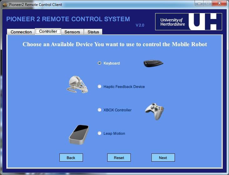
157 APPENDIX 146

158 APPENDIX 147
159 APPENDIX Sample Codes C++ header file of device connection and force rendering. #pragma once #include "stdafx.h" #include <AnyHapticsDevice.h> #include <HapticPositionFunctionEffect.h> #include <HapticSpring.h> #include <ParsedFunction.h> #include <HapticPrimitive.h> #include <FrictionSurface.h> #include <GodObjectRenderer.h> #include <HapticShapeConstraint.h> #include <HapticForceField.h> namespace uk { namespace herts { namespace pioneer { namespace client { namespace inputs { namespace haptic { using namespace HAPI; class CHapticController { private: AnyHapticsDevice hapticcontroller; //defines the dead zone int FORWARD_THRESHOLD; int BACKWARD_THRESHOLD; int LEFT_THRESHOLD; int RIGHT_THRESHOLD; position, in order to prevent sending flood cmds whether it has been pressed or released sonars considered moving direction forward all sonars reading //used to check the device int falconflag; int boolforward; int boolbackward; int boolleft; int boolright; //check the button status, int btnstatus; int directionminrangef; //the minimum sonar range among int directionminrangel; int directionminranger; int TotalMinRange; //the minimum sonar range among int minrangeidf; //the sonar ID which has minimum int minrangeidl; int minrangeidr; int temprange; //used to check the force effect status, in order to prevent generating force repetitively 148
160 APPENDIX int boolfarspringforce; int boolmidspringforce; int boolendspringforce; int boolforwardspringforce; int boolrfarspringforce; int boolrendspringforce; int boolbackwardspringforce; int sonardata[16]; int boolinitforce; *updown_effect; *backward_effect; HapticPositionFunctionEffect HapticPositionFunctionEffect char str[7]; //store cmd int cmdturn; HAPI::ParsedFunction * x_function; HAPI::ParsedFunction * y_function; HAPI::ParsedFunction * z_function; HapticSpring *FBSpringForce; int shape_c_mode; //is it in Shape Constraint mode int Block[8][59]; //[x][0]:whether the sonar reading is smaller than 300mm; //[x][1]:whether the ID is active HAPISurfaceObject *my_surface; HapticPrimitive *shapel; HapticPrimitive *shapefl; HapticPrimitive *shapef1; HapticPrimitive *shapef2; HapticPrimitive *shapefr; HapticPrimitive *shaper; HapticPrimitive *shaperear; HapticForceField *forceeffect; HAPI::Vec3 force; int boolforcefieldf; int boolforcefieldl; int boolforcefieldr; public: int m_connstatus; int m_forceeffectid; CHapticController(); ~CHapticController(); CHapticController(int i); int InitDevice(); void InitForce(); 149
161 APPENDIX sonarflag); void GetCMD(char** cmd, int int GetSonar(int *sonarrange); int ForceField(); int ShapeEffect(); void CloseDevice(); } } } } } } }; float RadiusValue(int id); 150
162 APPENDIX The following codes are part of the source file of proposed environmental force effect rendering. Only the condition when the robot is moving forward is shown. //get the current position of the haptic probe int fbpos =ceilf(hapticcontroller.getposition().z*1000); //move forward if (fbpos<-25) { //generate different level forces according to sonar readings if (sonardata[3] <= 800 sonardata[4] <= 800 sonardata[1] <= 550 sonardata[59] <= 650 sonardata[59] <= 650 sonardata[6] <= 550) { if (sonardata[3] <= 400 sonardata[4] <= 400 sonardata[1] <= 350 sonardata[59] <= 350 sonardata[59] <= 350 sonardata[6] <= 350) { if (boolendspringforce==0) //no max level spring force yet { hapticcontroller.cleareffects(); boolinitforce=0; boolfarspringforce=0; boolmidspringforce=0; z*0","x,y,z"); 0*z","x,y,z"); (z+0.015)*700","x,y,z"); x_function = new ParsedFunction(); x_function->setfunctionstring("-x* * y + y_function = new ParsedFunction(); y_function->setfunctionstring("x*0-500 * y - z_function = new ParsedFunction(); z_function->setfunctionstring("x*0 + 0 * y - updown_effect= new HapticPositionFunctionEffect (x_function,y_function, z_function); it will be used to // Send the effect to the haptic loop and from now on hapticcontroller.addeffect( updown_effect ); // send forces to the device. hapticcontroller.transferobjects(); boolendspringforce=1; } } else if (sonardata[3] <= 600 sonardata[4] <= 600 sonardata[1] <= 450 sonardata[59] <= 500 sonardata[59] <= 500 sonardata[6] <= 450) { if (boolmidspringforce==0&&boolendspringforce==0) //no middle level spring force yet { hapticcontroller.cleareffects(); boolinitforce=0; boolfarspringforce=0; boolendspringforce=0; z*0","x,y,z"); x_function = new ParsedFunction(); x_function->setfunctionstring("-x* * y + y_function = new ParsedFunction(); 151
163 APPENDIX 0*z","x,y,z"); (z+0.015)*500","x,y,z"); y_function->setfunctionstring("x*0-500 * y - z_function = new ParsedFunction(); z_function->setfunctionstring("x*0 + 0 * y - updown_effect= new HapticPositionFunctionEffect(x_function,y_function, z_function); it will be used to hapticcontroller.addeffect( updown_effect ); // Send the effect to the haptics loop and from now on // send forces to the device. hapticcontroller.transferobjects(); boolmidspringforce=1; } } else //far from obstacles { if (boolfarspringforce==0&&boolmidspringforce==0&&boolendspringforce==0) //no spring force yet { hapticcontroller.cleareffects(); boolinitforce=0; boolmidspringforce=0; boolendspringforce=0; z*0","x,y,z"); 0*z","x,y,z"); (z+0.015)*300","x,y,z"); x_function = new ParsedFunction(); x_function->setfunctionstring("-x* * y + y_function = new ParsedFunction(); y_function->setfunctionstring("x*0-500 * y - z_function = new ParsedFunction(); z_function->setfunctionstring("x*0 + 0 * y - updown_effect= new HapticPositionFunctionEffect(x_function,y_function, z_function); it will be used to hapticcontroller.addeffect( updown_effect ); // Send the effect to the haptics loop and from now on // send forces to the device. } } hapticcontroller.transferobjects(); boolfarspringforce=1; } else { boolforwardspringforce=1; boolforwardspringforce=0; if (boolinitforce!= 1) 152
164 APPENDIX { hapticcontroller.cleareffects(); boolfarspringforce = 0; boolmidspringforce = 0; boolendspringforce = 0; boolrfarspringforce = 0; boolrendspringforce = 0; boolforwardspringforce = 0; boolbackwardspringforce = 0; InitForce(); } } } else if (fbpos>=-25 && fbpos<=-4) { if (Block[59][1] == 1 boolforwardspringforce == 1 boolbackwardspringforce == 1 Block[6][1] == 1) { if (boolinitforce!= 1) { hapticcontroller.cleareffects(); boolfarspringforce = 0; boolmidspringforce = 0; boolendspringforce = 0; boolrfarspringforce = 0; boolrendspringforce = 0; } } } boolforwardspringforce = 0; boolbackwardspringforce = 0; InitForce(); 153
165 APPENDIX The following codes are part of the source file of proposed contact force effect rendering. //check whether the shape mode is enabled if (shape_c_mode) { for (int i=0;i<8;i++) { //[x][0]:whether the sonar reading is smaller than 300mm; if (Block[i][0]==1) { //[x][1]:whether the ID is active //also means whether the shape has been generated if (Block[i][1]!=1) { //if not, add relevant shape effect here! switch (i) { //object on the left case 0: { shapel = new HapticPrimitive( new Collision::AABox(Vec3(-0.1, - 0.1, -0.3), Vec3(-0.01, 0.1, 0.015)), my_surface, Collision::FRONT); hapticcontroller.addshape(shapel); hapticcontroller.transferobjects(); break; } //object on the left front case 1: { shapefl = new HapticPrimitive( new Collision::AABox(Vec3(-0.1, - 0.1, -0.3),Vec3(0.01, 0.1, )),my_surface,Collision::FRONT); hapticcontroller.addshape(shapefl); hapticcontroller.transferobjects(); break; } //object in the front case 2: { shapef1 = new HapticPrimitive( new Collision::AABox(Vec3(-0.1, - 0.1, -0.3),Vec3(0.1, 0.1,-0.045)),my_surface,Collision::FRONT); hapticcontroller.addshape(shapef1); hapticcontroller.transferobjects(); shapef2 = new HapticPrimitive( new Collision::AABox(Vec3(-0.1, - 0.1, -0.3),Vec3(0.1, 0.1,-0.025)),my_surface,Collision::FRONT); hapticcontroller.addshape(shapef2); hapticcontroller.transferobjects(); break; } //object on the right front case 3: { shapefr = new HapticPrimitive( new Collision::AABox(Vec3(-0.01, -0.1, -0.3),Vec3(0.1, 0.1, )),my_surface,Collision::FRONT); hapticcontroller.addshape(shapefr); hapticcontroller.transferobjects(); 154
166 APPENDIX break; } //object on the right case 4: { shaper = new HapticPrimitive( new Collision::AABox(Vec3(0.01, - 0.1, -0.3), Vec3(0.1, 0.1, 0.015)), my_surface, Collision::FRONT); hapticcontroller.addshape(shaper); hapticcontroller.transferobjects(); break; } case 5: { break; } case 6: { shaperear = new HapticPrimitive( new Collision::AABox(Vec3(-0.1, - 0.1, ), Vec3(0.1, 0.1, 0.2)), my_surface, Collision::FRONT); hapticcontroller.addshape(shaperear); hapticcontroller.transferobjects(); break; } case 7: { break; } default: { shapef2 = new HapticPrimitive( new Collision::AABox(Vec3(-0.1, - 0.1, -0.3),Vec3(0.1, 0.1,-0.015)),my_surface,Collision::FRONT); break; } } //the shape has been generated, change the status Block[i][1]=1; } } //if the sonar reading is larger than 300mm, remove the shape effect else { if (Block[i][1]==1) { //remove relevant shape effect here! switch (i) { case 0: { hapticcontroller.removeshape(shapel); hapticcontroller.transferobjects(); break; } case 1: { Block[i][1]=0; 155
167 APPENDIX hapticcontroller.removeshape(shapefl); hapticcontroller.transferobjects(); Block[i][1]=0; break; } case 2: { hapticcontroller.removeshape(shapef1); hapticcontroller.transferobjects(); hapticcontroller.removeshape(shapef2); hapticcontroller.transferobjects(); Block[i][1]=0; break; } case 3: { hapticcontroller.removeshape(shapefr); hapticcontroller.transferobjects(); Block[i][1]=0; break; } case 4: { hapticcontroller.removeshape(shaper); hapticcontroller.transferobjects(); break; } case 5: { Block[i][1]=0; Block[i][1]=0; break; } case 6: { hapticcontroller.removeshape(shaperear); hapticcontroller.transferobjects(); break; } case 7: { Block[i][1]=0; Block[i][1]=0; } break; } default: { break; } } 156
168 APPENDIX } } } //if the shape mode is disabled, remove existing shape effect else { for (int i=0;i<8;i++) { if (Block[i][1]==1) { //remove relevant shape effect here! switch (i) { case 0: { hapticcontroller.removeshape(shapel); hapticcontroller.transferobjects(); Block[i][1]=0; break; } case 1: { hapticcontroller.removeshape(shapefl); hapticcontroller.transferobjects(); Block[i][1]=0; break; } case 2: { hapticcontroller.removeshape(shapef1); hapticcontroller.transferobjects(); hapticcontroller.removeshape(shapef2); hapticcontroller.transferobjects(); Block[i][1]=0; break; } case 3: { hapticcontroller.removeshape(shapefr); hapticcontroller.transferobjects(); Block[i][1]=0; break; } case 4: { hapticcontroller.removeshape(shaper); hapticcontroller.transferobjects(); break; } case 5: { Block[i][1]=0; Block[i][1]=0; break; 157
169 APPENDIX } case 6: { hapticcontroller.removeshape(shaperear); hapticcontroller.transferobjects(); break; } case 7: { Block[i][1]=0; Block[i][1]=0; } break; } default: { break; } } } } 158
170 APPENDIX Questionnaire Sample of the Experiment A Background 1. What s your gender? male female 2. What s your age? How frequently do you play racing games? more than once a day about once a day more than once a week more than once a month less than once a month I normally do not play computer games 4. How many hours do you typically spend on playing games in one week? Less than 5hours 5hours~10hours more than 10hours 5. For a racing game do you prefer using keyboard or Game Controller or Joystick? Keyboard Joystick Game Controller 159
171 APPENDIX Questionnaire form 1. How natural was the mechanism, which controlled movement through the environment? Poor Excellent 2. How consistent was the information coming from visual feedback and force feedback? (What you see is what you touch?) Low High 3. How much precise can you perceive the relative distance to the obstacle by performing this trial? Low High 4. How much did the force feedback function interfere or distract you from performing assigned tasks or required activities? High Low 5. How much eyestrain by performing this trial? High Low 6. How much tired of your arm by performing this trial? High Low 7. Overall satisfaction. Poor Excellent 160
172 APPENDIX Questionnaire Sample of the Experiment B Instructions Researchers: Yangjun Chen, Giordano Settimo Supervisor: Dr. Salvatore Livatino (s.livatino@herts.ac.uk) This project is based on the development of different 3D display and a force feedback controller to teleoperate a mobile robot. During the test, we will use a Pioneer 2 DX robot. The task of a test will be to drive the Pioneer robot along a path avoiding collision. Then, you will be asked to communicate your impressions to the test monitor and to fill in a brief questionnaire. The test will be divided into 4 steps: 1. Instructions 2. Consent form 3. Task execution 4. Questionnaire completion Participation in this test is absolutely voluntary. If you feel uncomfortable or want to stop the test for any reasons, you can stop the test. During the test might be taken pictures or video. All the collected data may be used for research and may be published. Nonetheless, all the information you provide is confidential and will remain anonymous. Task description The user will drive the robot along a path bordered by boxes. The task is to complete the trial of keeping the robot, as much as possible, in the centre position of the path and thus avoiding collisions with the boxes. In the first phase user is free to become familiar with the haptic controller. Then will be proposed, in an order determined by those who monitors the test, one of four visualization methods; the user must drive for the half of the path using the force feedback and the other half without it. Completed a trial, the user needs to answer the questions (with and without force feedback) of the function that is used and then perform another test with another type of display, up to test all four types. Monitor Instructions Preliminary 1. Fix cameras on the robot and check if they correct orientation and focus. 2. Fix the haptic control, turn it on. 3. Turn on the robot. Place laptop on the robot and connect them (serial/serial-to-usb-cable). Then, connect USB Stereo webcam and the laser scanner. 4. Create an ad - hoc network between client and server laptops. 5. Run the Server application on the server laptop 6. Run the Client application on the client laptop 7. From the client connect to the server and run the stereo camera. 161
173 APPENDIX 8. Make sure the user become familiar with the haptic controller. 9. Start the test During the test End 1. Start the 3D visualization that you want to test 2. Write the information about the test: date, time, etc. 3. Move the robot in the start position 4. Turn on the log functionalities to save information about sonar and laser 5. Start the trial with the user 6. When the half of the path is reached by the user, stop the trial and turn off the force feedback 7. Continue the trial and finish the path 8. During all the trial write down the number of the collision 9. Stop the automatic log in client 1. Give the questionnaire for the 3D display that the users have tested. 2. Repeat again with another 3D display. 162
174 APPENDIX Background Thank you to participate in the user study. The purpose of this questionnaire is to know your satisfaction with the user study and the device you just tested. We want to collect some data about our participants. All the information you provide is confidential and will remain anonymous. The information you provide won't be used for any other purpose. 1. How old are you? Years old. 2. What is your gender? M F 3. Are you wearing glasses or contact lenses? glasses contact lenses neither 4. Do you have any visual impairment (e.g. Colour blindness)? Yes No 5. Which is your highest finished educational level? PhD Undergraduate student (BSc) Graduate student (Msc) 6. How long have you been using computers? Years. 7. How many hours per week do you approximately spend using computers? hours. 8. Do you play 3D computer games? If you do, how many hours during a week? Yes, hours per week. No 9. What is your degree of knowledge about robotics? Novice Beginner Expert 10. Have you ever taken part into a tele-robotic experiment before? Yes No 163
175 APPENDIX Consent form Project Title: 3D Displays with force feedback controller evaluation Researchers: Supervisor: Yangjun Chen, Giordano Settimo Dr. Salvatore Livatino o o o o o I have received information about this research project. I understand the purpose of the research project and my involvement in it. I understand that I may withdraw from the research project at any stage. I understand that my personal result will remain confidential and I wouldn't be indented if the information may be published. I have been informed that might be taken pictures and videos during the study, which may be published. I agree with the term above and indicate my agreement by signing here: Name of participant: Date: Signature: 164
? Very bad (negative) -3-2 -1 0 +1 +2 +3 Excellent (positive) 3.")
 -3-2 -1 0 +1 +2 +3 Excellent (positive) 4. How would you rate the comfort experience (in terms of eye strain, headache, nausea, tiredness)?")
176 APPENDIX Questionnaire forms 3-D TV with Force Feedback 1. How would you rate the obtained 3D depth impression? Very bad (negative) Excellent (positive) 2. How would you rate the overall sense of presence achieved (feeling to be there)? Very bad (negative) Excellent (positive) 3. You receive information about the remote environment, both through visual feedback and haptic feedback. Do you think that these two types of inputs that you perceive are consistent between each other? Very bad (negative) Excellent (positive) 4. How would you rate the comfort experience (in terms of eye strain, headache, nausea, tiredness)? Very bad (negative) Excellent (positive) 5. How would you rate haptic perception (realistic feeling of obstacles and shapes)? Very bad (negative) Excellent (positive) 6. How would you rate the general sense of the isolation from the surrounding environment? Very bad (negative) Excellent (positive) 165
Interactive Simulation: UCF EIN5255. VR Software. Audio Output. Page 4-1
 VR Software Class 4 Dr. Nabil Rami http://www.simulationfirst.com/ein5255/ Audio Output Can be divided into two elements: Audio Generation Audio Presentation Page 4-1 Audio Generation A variety of audio
Development of a telepresence agent
 Author: Chung-Chen Tsai, Yeh-Liang Hsu (2001-04-06); recommended: Yeh-Liang Hsu (2001-04-06); last updated: Yeh-Liang Hsu (2004-03-23). Note: This paper was first presented at. The revised paper was presented
VR/AR Concepts in Architecture And Available Tools
 VR/AR Concepts in Architecture And Available Tools Peter Kán Interactive Media Systems Group Institute of Software Technology and Interactive Systems TU Wien Outline 1. What can you do with virtual reality
Cognitive robots and emotional intelligence Cloud robotics Ethical, legal and social issues of robotic Construction robots Human activities in many
 Preface The jubilee 25th International Conference on Robotics in Alpe-Adria-Danube Region, RAAD 2016 was held in the conference centre of the Best Western Hotel M, Belgrade, Serbia, from 30 June to 2 July
* Intelli Robotic Wheel Chair for Specialty Operations & Physically Challenged
 ADVANCED ROBOTICS SOLUTIONS * Intelli Mobile Robot for Multi Specialty Operations * Advanced Robotic Pick and Place Arm and Hand System * Automatic Color Sensing Robot using PC * AI Based Image Capturing
Chapter 2 Introduction to Haptics 2.1 Definition of Haptics
 Chapter 2 Introduction to Haptics 2.1 Definition of Haptics The word haptic originates from the Greek verb hapto to touch and therefore refers to the ability to touch and manipulate objects. The haptic
NCCT IEEE PROJECTS ADVANCED ROBOTICS SOLUTIONS. Latest Projects, in various Domains. Promise for the Best Projects
 NCCT Promise for the Best Projects IEEE PROJECTS in various Domains Latest Projects, 2009-2010 ADVANCED ROBOTICS SOLUTIONS EMBEDDED SYSTEM PROJECTS Microcontrollers VLSI DSP Matlab Robotics ADVANCED ROBOTICS
Input devices and interaction. Ruth Aylett
 Input devices and interaction Ruth Aylett Contents Tracking What is available Devices Gloves, 6 DOF mouse, WiiMote Why is it important? Interaction is basic to VEs We defined them as interactive in real-time
Novel machine interface for scaled telesurgery
 Novel machine interface for scaled telesurgery S. Clanton, D. Wang, Y. Matsuoka, D. Shelton, G. Stetten SPIE Medical Imaging, vol. 5367, pp. 697-704. San Diego, Feb. 2004. A Novel Machine Interface for
Haptic presentation of 3D objects in virtual reality for the visually disabled
 Haptic presentation of 3D objects in virtual reality for the visually disabled M Moranski, A Materka Institute of Electronics, Technical University of Lodz, Wolczanska 211/215, Lodz, POLAND marcin.moranski@p.lodz.pl,
Visuo-Haptic Interface for Teleoperation of Mobile Robot Exploration Tasks
 Visuo-Haptic Interface for Teleoperation of Mobile Robot Exploration Tasks Nikos C. Mitsou, Spyros V. Velanas and Costas S. Tzafestas Abstract With the spread of low-cost haptic devices, haptic interfaces
E90 Project Proposal. 6 December 2006 Paul Azunre Thomas Murray David Wright
 E90 Project Proposal 6 December 2006 Paul Azunre Thomas Murray David Wright Table of Contents Abstract 3 Introduction..4 Technical Discussion...4 Tracking Input..4 Haptic Feedack.6 Project Implementation....7
t t t rt t s s tr t Manuel Martinez 1, Angela Constantinescu 2, Boris Schauerte 1, Daniel Koester 1, and Rainer Stiefelhagen 1,2
 t t t rt t s s Manuel Martinez 1, Angela Constantinescu 2, Boris Schauerte 1, Daniel Koester 1, and Rainer Stiefelhagen 1,2 1 r sr st t t 2 st t t r t r t s t s 3 Pr ÿ t3 tr 2 t 2 t r r t s 2 r t ts ss
VIRTUAL REALITY Introduction. Emil M. Petriu SITE, University of Ottawa
 VIRTUAL REALITY Introduction Emil M. Petriu SITE, University of Ottawa Natural and Virtual Reality Virtual Reality Interactive Virtual Reality Virtualized Reality Augmented Reality HUMAN PERCEPTION OF
MECHANICAL DESIGN LEARNING ENVIRONMENTS BASED ON VIRTUAL REALITY TECHNOLOGIES
 INTERNATIONAL CONFERENCE ON ENGINEERING AND PRODUCT DESIGN EDUCATION 4 & 5 SEPTEMBER 2008, UNIVERSITAT POLITECNICA DE CATALUNYA, BARCELONA, SPAIN MECHANICAL DESIGN LEARNING ENVIRONMENTS BASED ON VIRTUAL
Head Tracking for Google Cardboard by Simond Lee
 Head Tracking for Google Cardboard by Simond Lee (slee74@student.monash.edu) Virtual Reality Through Head-mounted Displays A head-mounted display (HMD) is a device which is worn on the head with screen
Dipartimento di Elettronica Informazione e Bioingegneria Robotics
 Dipartimento di Elettronica Informazione e Bioingegneria Robotics Behavioral robotics @ 2014 Behaviorism behave is what organisms do Behaviorism is built on this assumption, and its goal is to promote
Surgical robot simulation with BBZ console
 Review Article on Thoracic Surgery Surgical robot simulation with BBZ console Francesco Bovo 1, Giacomo De Rossi 2, Francesco Visentin 2,3 1 BBZ srl, Verona, Italy; 2 Department of Computer Science, Università
Perception. Read: AIMA Chapter 24 & Chapter HW#8 due today. Vision
 11-25-2013 Perception Vision Read: AIMA Chapter 24 & Chapter 25.3 HW#8 due today visual aural haptic & tactile vestibular (balance: equilibrium, acceleration, and orientation wrt gravity) olfactory taste
CENG 5931 HW 5 Mobile Robotics Due March 5. Sensors for Mobile Robots
 CENG 5931 HW 5 Mobile Robotics Due March 5 Sensors for Mobile Robots Dr. T. L. Harman: 281 283-3774 Office D104 For reports: Read HomeworkEssayRequirements on the web site and follow instructions which
Classifying 3D Input Devices
 IMGD 5100: Immersive HCI Classifying 3D Input Devices Robert W. Lindeman Associate Professor Department of Computer Science Worcester Polytechnic Institute gogo@wpi.edu Motivation The mouse and keyboard
Virtual Environments. Ruth Aylett
 Virtual Environments Ruth Aylett Aims of the course 1. To demonstrate a critical understanding of modern VE systems, evaluating the strengths and weaknesses of the current VR technologies 2. To be able
Team Autono-Mo. Jacobia. Department of Computer Science and Engineering The University of Texas at Arlington
 Department of Computer Science and Engineering The University of Texas at Arlington Team Autono-Mo Jacobia Architecture Design Specification Team Members: Bill Butts Darius Salemizadeh Lance Storey Yunesh
University of Toronto. Companion Robot Security. ECE1778 Winter Wei Hao Chang Apper Alexander Hong Programmer
 University of Toronto Companion ECE1778 Winter 2015 Creative Applications for Mobile Devices Wei Hao Chang Apper Alexander Hong Programmer April 9, 2015 Contents 1 Introduction 3 1.1 Problem......................................
Practical Data Visualization and Virtual Reality. Virtual Reality VR Display Systems. Karljohan Lundin Palmerius
 Practical Data Visualization and Virtual Reality Virtual Reality VR Display Systems Karljohan Lundin Palmerius Synopsis Virtual Reality basics Common display systems Visual modality Sound modality Interaction
ReVRSR: Remote Virtual Reality for Service Robots
 ReVRSR: Remote Virtual Reality for Service Robots Amel Hassan, Ahmed Ehab Gado, Faizan Muhammad March 17, 2018 Abstract This project aims to bring a service robot s perspective to a human user. We believe
Kinect Interface for UC-win/Road: Application to Tele-operation of Small Robots
 Kinect Interface for UC-win/Road: Application to Tele-operation of Small Robots Hafid NINISS Forum8 - Robot Development Team Abstract: The purpose of this work is to develop a man-machine interface for
Advancements in Gesture Recognition Technology
 IOSR Journal of VLSI and Signal Processing (IOSR-JVSP) Volume 4, Issue 4, Ver. I (Jul-Aug. 2014), PP 01-07 e-issn: 2319 4200, p-issn No. : 2319 4197 Advancements in Gesture Recognition Technology 1 Poluka
CONTROLLING METHODS AND CHALLENGES OF ROBOTIC ARM
 CONTROLLING METHODS AND CHALLENGES OF ROBOTIC ARM Aniket D. Kulkarni *1, Dr.Sayyad Ajij D. *2 *1(Student of E&C Department, MIT Aurangabad, India) *2(HOD of E&C department, MIT Aurangabad, India) aniket2212@gmail.com*1,
HMD based VR Service Framework. July Web3D Consortium Kwan-Hee Yoo Chungbuk National University
 HMD based VR Service Framework July 31 2017 Web3D Consortium Kwan-Hee Yoo Chungbuk National University khyoo@chungbuk.ac.kr What is Virtual Reality? Making an electronic world seem real and interactive
Medical robotics and Image Guided Therapy (IGT) Bogdan M. Maris, PhD Temporary Assistant Professor
 Bogdan M. Maris, PhD Temporary Assistant Professor") Medical robotics and Image Guided Therapy (IGT) Bogdan M. Maris, PhD Temporary Assistant Professor E-mail bogdan.maris@univr.it Medical Robotics History, current and future applications Robots are Accurate
Medical robotics and Image Guided Therapy (IGT) Bogdan M. Maris, PhD Temporary Assistant Professor E-mail bogdan.maris@univr.it Medical Robotics History, current and future applications Robots are Accurate
Force feedback interfaces & applications
 Force feedback interfaces & applications Roope Raisamo Tampere Unit for Computer-Human Interaction (TAUCHI) School of Information Sciences University of Tampere, Finland Based on material by Jukka Raisamo,
Blind navigation with a wearable range camera and vibrotactile helmet
 Blind navigation with a wearable range camera and vibrotactile helmet (author s name removed for double-blind review) X university 1@2.com (author s name removed for double-blind review) X university 1@2.com
AGENT PLATFORM FOR ROBOT CONTROL IN REAL-TIME DYNAMIC ENVIRONMENTS. Nuno Sousa Eugénio Oliveira
 AGENT PLATFORM FOR ROBOT CONTROL IN REAL-TIME DYNAMIC ENVIRONMENTS Nuno Sousa Eugénio Oliveira Faculdade de Egenharia da Universidade do Porto, Portugal Abstract: This paper describes a platform that enables
Haptics CS327A
 Haptics CS327A - 217 hap tic adjective relating to the sense of touch or to the perception and manipulation of objects using the senses of touch and proprioception 1 2 Slave Master 3 Courtesy of Walischmiller
LDOR: Laser Directed Object Retrieving Robot. Final Report
 University of Florida Department of Electrical and Computer Engineering EEL 5666 Intelligent Machines Design Laboratory LDOR: Laser Directed Object Retrieving Robot Final Report 4/22/08 Mike Arms TA: Mike
Human Robot Interaction (HRI)
") Brief Introduction to HRI Batu Akan batu.akan@mdh.se Mälardalen Högskola September 29, 2008 Overview 1 Introduction What are robots What is HRI Application areas of HRI 2 3 Motivations Proposed Solution
Brief Introduction to HRI Batu Akan batu.akan@mdh.se Mälardalen Högskola September 29, 2008 Overview 1 Introduction What are robots What is HRI Application areas of HRI 2 3 Motivations Proposed Solution
Sensors & Systems for Human Safety Assurance in Collaborative Exploration
 Sensing and Sensors CMU SCS RI 16-722 S09 Ned Fox nfox@andrew.cmu.edu Outline What is collaborative exploration? Humans sensing robots Robots sensing humans Overseers sensing both Inherently safe systems
TOUCH & FEEL VIRTUAL REALITY. DEVELOPMENT KIT - VERSION NOVEMBER 2017
 TOUCH & FEEL VIRTUAL REALITY DEVELOPMENT KIT - VERSION 1.1 - NOVEMBER 2017 www.neurodigital.es Minimum System Specs Operating System Windows 8.1 or newer Processor AMD Phenom II or Intel Core i3 processor
3D User Interfaces. Using the Kinect and Beyond. John Murray. John Murray
 Using the Kinect and Beyond // Center for Games and Playable Media // http://games.soe.ucsc.edu John Murray John Murray Expressive Title Here (Arial) Intelligence Studio Introduction to Interfaces User
Haptic Camera Manipulation: Extending the Camera In Hand Metaphor
 Haptic Camera Manipulation: Extending the Camera In Hand Metaphor Joan De Boeck, Karin Coninx Expertise Center for Digital Media Limburgs Universitair Centrum Wetenschapspark 2, B-3590 Diepenbeek, Belgium
DESIGN STYLE FOR BUILDING INTERIOR 3D OBJECTS USING MARKER BASED AUGMENTED REALITY
 DESIGN STYLE FOR BUILDING INTERIOR 3D OBJECTS USING MARKER BASED AUGMENTED REALITY 1 RAJU RATHOD, 2 GEORGE PHILIP.C, 3 VIJAY KUMAR B.P 1,2,3 MSRIT Bangalore Abstract- To ensure the best place, position,
MULTI-LAYERED HYBRID ARCHITECTURE TO SOLVE COMPLEX TASKS OF AN AUTONOMOUS MOBILE ROBOT
 MULTI-LAYERED HYBRID ARCHITECTURE TO SOLVE COMPLEX TASKS OF AN AUTONOMOUS MOBILE ROBOT F. TIECHE, C. FACCHINETTI and H. HUGLI Institute of Microtechnology, University of Neuchâtel, Rue de Tivoli 28, CH-2003
HeroX - Untethered VR Training in Sync'ed Physical Spaces
 Page 1 of 6 HeroX - Untethered VR Training in Sync'ed Physical Spaces Above and Beyond - Integrating Robotics In previous research work I experimented with multiple robots remotely controlled by people
Determining Optimal Player Position, Distance, and Scale from a Point of Interest on a Terrain
 Technical Disclosure Commons Defensive Publications Series October 02, 2017 Determining Optimal Player Position, Distance, and Scale from a Point of Interest on a Terrain Adam Glazier Nadav Ashkenazi Matthew
Perception in Immersive Virtual Reality Environments ROB ALLISON DEPT. OF ELECTRICAL ENGINEERING AND COMPUTER SCIENCE YORK UNIVERSITY, TORONTO
 Perception in Immersive Virtual Reality Environments ROB ALLISON DEPT. OF ELECTRICAL ENGINEERING AND COMPUTER SCIENCE YORK UNIVERSITY, TORONTO Overview Basic concepts and ideas of virtual environments
Augmented and Virtual Reality
 CS-3120 Human-Computer Interaction Augmented and Virtual Reality Mikko Kytö 7.11.2017 From Real to Virtual [1] Milgram, P., & Kishino, F. (1994). A taxonomy of mixed reality visual displays. IEICE TRANSACTIONS
Abdulmotaleb El Saddik Associate Professor Dr.-Ing., SMIEEE, P.Eng.
 Abdulmotaleb El Saddik Associate Professor Dr.-Ing., SMIEEE, P.Eng. Multimedia Communications Research Laboratory University of Ottawa Ontario Research Network of E-Commerce www.mcrlab.uottawa.ca abed@mcrlab.uottawa.ca
ROBCHAIR - A SEMI-AUTONOMOUS WHEELCHAIR FOR DISABLED PEOPLE. G. Pires, U. Nunes, A. T. de Almeida
 ROBCHAIR - A SEMI-AUTONOMOUS WHEELCHAIR FOR DISABLED PEOPLE G. Pires, U. Nunes, A. T. de Almeida Institute of Systems and Robotics Department of Electrical Engineering University of Coimbra, Polo II 3030
Introduction to Virtual Reality (based on a talk by Bill Mark)
") Introduction to Virtual Reality (based on a talk by Bill Mark) I will talk about... Why do we want Virtual Reality? What is needed for a VR system? Examples of VR systems Research problems in VR Most Computers
Introduction to Virtual Reality (based on a talk by Bill Mark) I will talk about... Why do we want Virtual Reality? What is needed for a VR system? Examples of VR systems Research problems in VR Most Computers
An Autonomous Self- Propelled Robot Designed for Obstacle Avoidance and Fire Fighting
 An Autonomous Self- Propelled Robot Designed for Obstacle Avoidance and Fire Fighting K. Prathyusha Assistant professor, Department of ECE, NRI Institute of Technology, Agiripalli Mandal, Krishna District,
Humanoid robot. Honda's ASIMO, an example of a humanoid robot
 Humanoid robot Honda's ASIMO, an example of a humanoid robot A humanoid robot is a robot with its overall appearance based on that of the human body, allowing interaction with made-for-human tools or environments.
- applications on same or different network node of the workstation - portability of application software - multiple displays - open architecture
 12 Window Systems - A window system manages a computer screen. - Divides the screen into overlapping regions. - Each region displays output from a particular application. X window system is widely used
HandsIn3D: Supporting Remote Guidance with Immersive Virtual Environments
 HandsIn3D: Supporting Remote Guidance with Immersive Virtual Environments Weidong Huang 1, Leila Alem 1, and Franco Tecchia 2 1 CSIRO, Australia 2 PERCRO - Scuola Superiore Sant Anna, Italy {Tony.Huang,Leila.Alem}@csiro.au,
Virtual Co-Location for Crime Scene Investigation and Going Beyond
 Virtual Co-Location for Crime Scene Investigation and Going Beyond Stephan Lukosch Faculty of Technology, Policy and Management, Systems Engineering Section Delft University of Technology Challenge the
Welcome to this course on «Natural Interactive Walking on Virtual Grounds»!
 Welcome to this course on «Natural Interactive Walking on Virtual Grounds»! The speaker is Anatole Lécuyer, senior researcher at Inria, Rennes, France; More information about him at : http://people.rennes.inria.fr/anatole.lecuyer/
A Kinect-based 3D hand-gesture interface for 3D databases
 A Kinect-based 3D hand-gesture interface for 3D databases Abstract. The use of natural interfaces improves significantly aspects related to human-computer interaction and consequently the productivity
REPORT ON THE CURRENT STATE OF FOR DESIGN. XL: Experiments in Landscape and Urbanism
 REPORT ON THE CURRENT STATE OF FOR DESIGN XL: Experiments in Landscape and Urbanism This report was produced by XL: Experiments in Landscape and Urbanism, SWA Group s innovation lab. It began as an internal
Formation and Cooperation for SWARMed Intelligent Robots
 Formation and Cooperation for SWARMed Intelligent Robots Wei Cao 1 Yanqing Gao 2 Jason Robert Mace 3 (West Virginia University 1 University of Arizona 2 Energy Corp. of America 3 ) Abstract This article
Virtual Reality in Neuro- Rehabilitation and Beyond
 Virtual Reality in Neuro- Rehabilitation and Beyond Amanda Carr, OTRL, CBIS Origami Brain Injury Rehabilitation Center Director of Rehabilitation Amanda.Carr@origamirehab.org Objectives Define virtual
Multi-sensory Tracking of Elders in Outdoor Environments on Ambient Assisted Living
 Multi-sensory Tracking of Elders in Outdoor Environments on Ambient Assisted Living Javier Jiménez Alemán Fluminense Federal University, Niterói, Brazil jjimenezaleman@ic.uff.br Abstract. Ambient Assisted
Range Sensing strategies
 Range Sensing strategies Active range sensors Ultrasound Laser range sensor Slides adopted from Siegwart and Nourbakhsh 4.1.6 Range Sensors (time of flight) (1) Large range distance measurement -> called
ENHANCED HUMAN-AGENT INTERACTION: AUGMENTING INTERACTION MODELS WITH EMBODIED AGENTS BY SERAFIN BENTO. MASTER OF SCIENCE in INFORMATION SYSTEMS
 BY SERAFIN BENTO MASTER OF SCIENCE in INFORMATION SYSTEMS Edmonton, Alberta September, 2015 ABSTRACT The popularity of software agents demands for more comprehensive HAI design processes. The outcome of
Tele-Nursing System with Realistic Sensations using Virtual Locomotion Interface
 6th ERCIM Workshop "User Interfaces for All" Tele-Nursing System with Realistic Sensations using Virtual Locomotion Interface Tsutomu MIYASATO ATR Media Integration & Communications 2-2-2 Hikaridai, Seika-cho,
Collaborative Robotic Navigation Using EZ-Robots
 , October 19-21, 2016, San Francisco, USA Collaborative Robotic Navigation Using EZ-Robots G. Huang, R. Childers, J. Hilton and Y. Sun Abstract - Robots and their applications are becoming more and more
Touch Feedback in a Head-Mounted Display Virtual Reality through a Kinesthetic Haptic Device
 Touch Feedback in a Head-Mounted Display Virtual Reality through a Kinesthetic Haptic Device Andrew A. Stanley Stanford University Department of Mechanical Engineering astan@stanford.edu Alice X. Wu Stanford
preface Motivation Figure 1. Reality-virtuality continuum (Milgram & Kishino, 1994) Mixed.Reality Augmented. Virtuality Real...
 Mixed.Reality Augmented. Virtuality Real...") v preface Motivation Augmented reality (AR) research aims to develop technologies that allow the real-time fusion of computer-generated digital content with the real world. Unlike virtual reality (VR)
v preface Motivation Augmented reality (AR) research aims to develop technologies that allow the real-time fusion of computer-generated digital content with the real world. Unlike virtual reality (VR)
Jane Li. Assistant Professor Mechanical Engineering Department, Robotic Engineering Program Worcester Polytechnic Institute
 Jane Li Assistant Professor Mechanical Engineering Department, Robotic Engineering Program Worcester Polytechnic Institute Use an example to explain what is admittance control? You may refer to exoskeleton
A*STAR Unveils Singapore s First Social Robots at Robocup2010
 MEDIA RELEASE Singapore, 21 June 2010 Total: 6 pages A*STAR Unveils Singapore s First Social Robots at Robocup2010 Visit Suntec City to experience the first social robots - OLIVIA and LUCAS that can see,
Geo-Located Content in Virtual and Augmented Reality
 Technical Disclosure Commons Defensive Publications Series October 02, 2017 Geo-Located Content in Virtual and Augmented Reality Thomas Anglaret Follow this and additional works at: http://www.tdcommons.org/dpubs_series
LOOKING AHEAD: UE4 VR Roadmap. Nick Whiting Technical Director VR / AR
 LOOKING AHEAD: UE4 VR Roadmap Nick Whiting Technical Director VR / AR HEADLINE AND IMAGE LAYOUT RECENT DEVELOPMENTS RECENT DEVELOPMENTS At Epic, we drive our engine development by creating content. We
Tele-operation of a Robot Arm with Electro Tactile Feedback
 F Tele-operation of a Robot Arm with Electro Tactile Feedback Daniel S. Pamungkas and Koren Ward * Abstract Tactile feedback from a remotely controlled robotic arm can facilitate certain tasks by enabling
What was the first gestural interface?
 stanford hci group / cs247 Human-Computer Interaction Design Studio What was the first gestural interface? 15 January 2013 http://cs247.stanford.edu Theremin Myron Krueger 1 Myron Krueger There were things
Multisensory virtual environment for supporting blind persons acquisition of spatial cognitive mapping, orientation, and mobility skills
 Multisensory virtual environment for supporting blind persons acquisition of spatial cognitive mapping, orientation, and mobility skills O Lahav and D Mioduser School of Education, Tel Aviv University,
Omni-Directional Catadioptric Acquisition System
 Technical Disclosure Commons Defensive Publications Series December 18, 2017 Omni-Directional Catadioptric Acquisition System Andreas Nowatzyk Andrew I. Russell Follow this and additional works at: http://www.tdcommons.org/dpubs_series
Methods for Haptic Feedback in Teleoperated Robotic Surgery
 Young Group 5 1 Methods for Haptic Feedback in Teleoperated Robotic Surgery Paper Review Jessie Young Group 5: Haptic Interface for Surgical Manipulator System March 12, 2012 Paper Selection: A. M. Okamura.
Virtual Reality I. Visual Imaging in the Electronic Age. Donald P. Greenberg November 9, 2017 Lecture #21
 Virtual Reality I Visual Imaging in the Electronic Age Donald P. Greenberg November 9, 2017 Lecture #21 1968: Ivan Sutherland 1990s: HMDs, Henry Fuchs 2013: Google Glass History of Virtual Reality 2016:
Computer Graphics. Spring April Ghada Ahmed, PhD Dept. of Computer Science Helwan University
 Spring 2018 10 April 2018, PhD ghada@fcih.net Agenda Augmented reality (AR) is a field of computer research which deals with the combination of real-world and computer-generated data. 2 Augmented reality
MEAM 520. Haptic Rendering and Teleoperation
 MEAM 520 Haptic Rendering and Teleoperation Katherine J. Kuchenbecker, Ph.D. General Robotics, Automation, Sensing, and Perception Lab (GRASP) MEAM Department, SEAS, University of Pennsylvania Lecture
University of California, Santa Barbara. CS189 Fall 17 Capstone. VR Telemedicine. Product Requirement Documentation
 University of California, Santa Barbara CS189 Fall 17 Capstone VR Telemedicine Product Requirement Documentation Jinfa Zhu Kenneth Chan Shouzhi Wan Xiaohe He Yuanqi Li Supervised by Ole Eichhorn Helen
Virtual Reality Calendar Tour Guide
 Technical Disclosure Commons Defensive Publications Series October 02, 2017 Virtual Reality Calendar Tour Guide Walter Ianneo Follow this and additional works at: http://www.tdcommons.org/dpubs_series
Mechatronics Project Report
 Mechatronics Project Report Introduction Robotic fish are utilized in the Dynamic Systems Laboratory in order to study and model schooling in fish populations, with the goal of being able to manage aquatic
University of Florida Department of Electrical and Computer Engineering Intelligent Machine Design Laboratory EEL 4665 Spring 2013 LOSAT
 University of Florida Department of Electrical and Computer Engineering Intelligent Machine Design Laboratory EEL 4665 Spring 2013 LOSAT Brandon J. Patton Instructors: Drs. Antonio Arroyo and Eric Schwartz
Classifying 3D Input Devices
 IMGD 5100: Immersive HCI Classifying 3D Input Devices Robert W. Lindeman Associate Professor Department of Computer Science Worcester Polytechnic Institute gogo@wpi.edu But First Who are you? Name Interests
Motion Control of a Three Active Wheeled Mobile Robot and Collision-Free Human Following Navigation in Outdoor Environment
 Proceedings of the International MultiConference of Engineers and Computer Scientists 2016 Vol I,, March 16-18, 2016, Hong Kong Motion Control of a Three Active Wheeled Mobile Robot and Collision-Free
State Of The Union.. Past, Present, And Future Of Wearable Glasses. Salvatore Vilardi V.P. of Product Development Immy Inc.
 State Of The Union.. Past, Present, And Future Of Wearable Glasses Salvatore Vilardi V.P. of Product Development Immy Inc. Salvatore Vilardi Mobile Monday October 2016 1 Outline 1. The Past 2. The Present
Evaluation of a Tricycle-style Teleoperational Interface for Children: a Comparative Experiment with a Video Game Controller
 2012 IEEE RO-MAN: The 21st IEEE International Symposium on Robot and Human Interactive Communication. September 9-13, 2012. Paris, France. Evaluation of a Tricycle-style Teleoperational Interface for Children:
Depth-Enhanced Mobile Robot Teleguide based on Laser Images
 Depth-Enhanced Mobile Robot Teleguide based on Laser Images S. Livatino 1 G. Muscato 2 S. Sessa 2 V. Neri 2 1 School of Engineering and Technology, University of Hertfordshire, Hatfield, United Kingdom
VR based HCI Techniques & Application. November 29, 2002
 VR based HCI Techniques & Application November 29, 2002 stefan.seipel@hci.uu.se What is Virtual Reality? Coates (1992): Virtual Reality is electronic simulations of environments experienced via head mounted
Creating a 3D environment map from 2D camera images in robotics
 Creating a 3D environment map from 2D camera images in robotics J.P. Niemantsverdriet jelle@niemantsverdriet.nl 4th June 2003 Timorstraat 6A 9715 LE Groningen student number: 0919462 internal advisor:
By Pierre Olivier, Vice President, Engineering and Manufacturing, LeddarTech Inc.
 Leddar optical time-of-flight sensing technology, originally discovered by the National Optics Institute (INO) in Quebec City and developed and commercialized by LeddarTech, is a unique LiDAR technology
CS277 - Experimental Haptics Lecture 1. Introduction to Haptics
 CS277 - Experimental Haptics Lecture 1 Introduction to Haptics Haptic Interfaces Enables physical interaction with virtual objects Haptic Rendering Potential Fields Polygonal Meshes Implicit Surfaces Volumetric
Computer Assisted Medical Interventions
 Outline Computer Assisted Medical Interventions Force control, collaborative manipulation and telemanipulation Bernard BAYLE Joint course University of Strasbourg, University of Houston, Telecom Paris
Prospective Teleautonomy For EOD Operations
 Perception and task guidance Perceived world model & intent Prospective Teleautonomy For EOD Operations Prof. Seth Teller Electrical Engineering and Computer Science Department Computer Science and Artificial
Azaad Kumar Bahadur 1, Nishant Tripathi 2
 e-issn 2455 1392 Volume 2 Issue 8, August 2016 pp. 29 35 Scientific Journal Impact Factor : 3.468 http://www.ijcter.com Design of Smart Voice Guiding and Location Indicator System for Visually Impaired
Automated Mobility and Orientation System for Blind
 Automated Mobility and Orientation System for Blind Shradha Andhare 1, Amar Pise 2, Shubham Gopanpale 3 Hanmant Kamble 4 Dept. of E&TC Engineering, D.Y.P.I.E.T. College, Maharashtra, India. ---------------------------------------------------------------------***---------------------------------------------------------------------
Tele-operation of a robot arm with electro tactile feedback
 University of Wollongong Research Online Faculty of Engineering and Information Sciences - Papers: Part A Faculty of Engineering and Information Sciences 2013 Tele-operation of a robot arm with electro
MEng Project Proposals: Info-Communications
 Proposed Research Project (1): Chau Lap Pui elpchau@ntu.edu.sg Rain Removal Algorithm for Video with Dynamic Scene Rain removal is a complex task. In rainy videos pixels exhibit small but frequent intensity
CSE 165: 3D User Interaction. Lecture #14: 3D UI Design
 CSE 165: 3D User Interaction Lecture #14: 3D UI Design 2 Announcements Homework 3 due tomorrow 2pm Monday: midterm discussion Next Thursday: midterm exam 3D UI Design Strategies 3 4 Thus far 3DUI hardware
Effective Iconography....convey ideas without words; attract attention...
 Effective Iconography...convey ideas without words; attract attention... Visual Thinking and Icons An icon is an image, picture, or symbol representing a concept Icon-specific guidelines Represent the