ABSTRACT... 4 ACKNOWLEDGEMENTS... 5 INTRODUCTION STATE OF THE ART ANALYSIS... 9
|
|
|
- Clemence Marsh
- 6 years ago
- Views:
Transcription

1
2 ABSTRACT... 4 ACKNOWLEDGEMENTS... 5 INTRODUCTION PROBLEM STATEMENT WORKFLOW OF THE PROPOSED SYSTEM RESEARCH QUESTIONS AND OUTLINE OF RESEARCH STATE OF THE ART ANALYSIS LITERATURE RESEARCH LOCALISATION TECHNIQUES INERTIAL EVALUATION OF DIFFERENT TECHNIQUES CRITERIA FOR TECHNOLOGY IN SHIPBUILDING ANALYSIS CONCLUSION OF THE LITERATURE REVIEW CURRENT WORKFLOW SHIPBUILDING PROCESS PROBLEM REPORTING AR IN SHIPBUILDING CURRENT SYSTEMS IDEATION STAKEHOLDERS VISIT TO THE DOCK AT VLISSINGEN OOST DESIGN PROCESS ADDITIONAL IDEAS PRODUCT REQUIREMENTS PRODUCT REALISATION COMPONENTS AND TECHNIQUES FUSION WITH OTHER SOFTWARE BUILDING THE APPLICATION CREATING ADF FILES SAVING MARKERS AND ADDITIONAL DATA MEASURING DISTANCES... 22
3 5.3.4 SENDING ERROR REPORTS BUILDING AN INTERFACE FUTURE FEATURES EVALUATION FUNCTIONAL TEST USE-CASE SCENARIO TESTING SETUP OF THE USE-CASE SCENARIO TEST COMMUNICATION AMONG WORKERS AREAS OF IMPROVEMENT CONCLUSION CONCLUSIONS AND ANSWERS TO THE RESEARCH QUESTION RECOMMENDATIONS AND DISCUSSION DIRECTIONS FOR FUTURE DEVELOPMENT APPENDIX TABLE GARTNER S HYPE CYCLE PHOTO OF THE DOCK IN VLISSINGEN OOST NOTES OF TRIP TO THE DOCK AT VLISSINGEN OOST (DUTCH) PICTURES OF THE DESIGN PROCESS USE-CASE SCENARIO USED FOR TESTING PICTURES OF THE APPLICATION THE MAIN MENU WRITING AN EXTERNAL REPORT AND ADDING AN ADF FILE ADDING MARKERS TO FIXED LOCATIONS IN 3D VIEWING AND EDITING INFORMATION FOR EACH MARKER (ADD ANNOTATION BUTTON HIGHLIGHTED BLUE) THE POPUP AFTER TAPPING THE NEW MARKER BUTTON IN THE LOWER RIGHT CORNER THE POPUP AFTER PRESSING DELETE ON THE SELECTED MARKER THE POPUP AFTER PRESSING THE MEASURE BUTTON (HIGHLIGHTED BLUE) SHOWING THE DISTANCE TO THE SELECTED MARKER THE CODE USED TO SAVE MARKERS IN THE EXAMPLE FROM THE TANGO SDK THE CODE USED TO GIVE EACH MARKER A UNIQUE ID THE COMPLETE CODE USED TO SAVE A MARKER CODE FOR EXPORTING ADF FILES XML ELEMENTS OF MARKERS MEASURING DISTANCES VARIABLES... 44
4 9.9 TYPICAL IN2CRM PROBLEM REPORT EXPORTED XML NOTES AND REMARKS OF TEST SUBJECTS CONSIDERING THE APPLICATION FORM USED FOR THE FUNCTIONAL TEST RESULTS OF THE FUNCTIONAL TEST PICTURES OF THE TESTING PHASE FUNCTIONAL TEST USE-CASE SCENARIO THE GAP THE BOX HAS TO FIT THROUGH IS MEASURED USING DIFFERENT COLOURED MARKERS THE PROBLEM IS FURTHER CLARIFIED USING MARKERS ERROR REPORTING SECTION REFERENCES Abstract An application is built for the shipbuilding industry that used Augmented Reality to provide the workers at the dock and engineers with a means to ease the communication process. Research is done to provide background literature on 3D positioning in ships under construction. The ideation process is described along with ideation for future projects. Requirements are set up, and an application is built using the Google Tango platform and tested for these requirements. Also the application is tested in a use-case scenario.
5 Acknowledgements I would like to thank my supervisors at the University of Twente; Dr. Job Zwiers and MSc Jan Kolkmeier, and my supervisor at DAMEN Björn Mes. The feedback provided by all three supervisors provided me with essential guidelines to get my research going in the right direction. The close cooperation with Björn at DAMEN provided me the opportunity to develop this application and gain experience working in a professional environment. I would like to thank DAMEN and Joep Broekhuijsen for the hardware provided to build the application. Lastly, I would like to thank my friends and family for the continuous support and feedback during this research.
6 Introduction In this research, a novel system is developed and described that aims to facilitate the communication during the process of building large (naval) ships. The design is aimed specifically at the communication between workers on the dock and engineers in the office. The result is a proof of concept application that runs on a Google Tango enabled smartphone. The application uses augmented reality to scan and annotate the environment, and allows these scans and annotations to be exported to another smartphone or an error reporting program used by the engineers. Firstly, a literature research and state of the art analysis is done to give an overview of available 3D positioning and mapping techniques and the possibility to use these during shipbuilding. Since the final application will need to be integrated in the workflow of shipbuilding, this workflow is also described in this research. Secondly, the problem regarding the communication during construction and the aim of the application is described. Thirdly, the ideation and design process is described, along with the requirements for the application. Then, the core part of this research, describes the realisation of the application. The application has been built using Unity along with the Google Tango SDK. Examples from this SDK are used and extended, and new code has been written to allow users to annotate, scan and measure the environment. Additional code is written to export the data created in XML format, to allow viewing of the data on a different smartphone or on a computer in error managing programs and 3D software. The resulting application has been tested for functionality and usability, but since the application is a proof of concept rather than an end product, testing possibilities are limited. Recommendations are made for steps that are needed to develop a functional application that can be implemented in the current workflow of shipbuilding.
7 1.1 Problem statement During the construction of a ship involves many problems and obstacles that require communication and cooperation to solve. This communication happens between engineers, between workers, and between works and engineers. The latter is often a problem, since the workers are located at the docks, and the engineers are located at the office. Currently, workers can report a problem by taking pictures, moving these pictures to the computer, and adding them as attachments to a problem report. This report can then be sent to the engineers. This method often takes a long time, and cannot be done on site, but requires a desktop computer. This communication process is rather slow. Also the communication between workers can be quite difficult, since this happens largely using text and pictures. When a worker encounters a problem that needs to be fixed by someone else, this problem has to be communicated somehow. The current method mainly uses handwritten text, which is later entered into the system either by typing it again on the computer, or uploading a picture of the handwritten text. This can be rather slow and inefficient, as handwritten text is not recognized by the computer (so it is not searchable) and sometimes not readable. Also this process requires a lot of time to report a problem Workflow of the proposed system A 3D positioning and scanning system can help solve this problem by allowing the workers to exactly specify where the problem occurs in the ship, and enabling them to communicate this directly to the engineers and to other workers. This system would operate on two locations, partially inside the ship that is being constructed on a handheld device that can be taken to the construction site, and partially in the office where the ship is designed, as a program on desktop computers. When a problem occurs inside the ship, a worker can use the system to scan the location, and add markers to exact positions. These markers can be used to place annotations, or to measure distances in the real world. The data on this can then be used to send a problem report to the engineers, allowing them to view the problem in 3D with exact locations and measurements readily available. This information can then be used by the engineers to provide feedback. This feedback can then be sent back to the worker, and through AR be superimposed on the situation inside the ship. Additionally, when a worker encounters a problem, comments from other workers and engineers can appear on his system too, providing detailed information available for all the people involved. 1.3 Research Questions and outline of research The problem statement leads to the following research question: How can currently existing AR technologies be implemented to create an application that will improve the communication between engineers and workers during ship construction, and provide a proof of concept to base future research on? Before this question can be answered there are other questions to consider: What technologies exist for determining a 3D position with a high enough resolution to use in shipbuilding? What are the limitations for a technology to be used during ship construction?
8 What is the best way to communicate the data obtained to another party? How can this application be integrated in the current workflow of shipbuilding? These research questions will be answered in the rest of this research. The four sub questions will be answered in Chapters 2, 3, 5 and 6. Chapter 2 will explore the available technologies for localisation in ships by providing a literature review and describing the current state of the art. Chapter 3 will describe the ideation process used to develop the system. Then in chapter 4 the requirements of the application will be analysed and formulated. In chapter 5 the realisation of the application will be described by giving an in depth walkthrough of the process. After that, the application is tested both for functionally and in a use-case scenario, this can be found in chapter Error! Reference source not found.. Chapter 7 will be a conclusion of the results found in this research and an answer to the research question and sub questions. Chapter 8 will cover the recommendations for the additions and changes to the application that are required to move from a proof-of-concept application to a functional application that can be implemented in the current workflow.
9 2 State of the art Analysis In this chapter, the state of the art technology in the field of 3D localisation has been analysed in regard to usability in shipbuilding environments. This has been done through a literature review on 3D positioning in shipbuilding, and by giving an overview of existing technologies for 3D positioning. Furthermore an overview of current communication workflows in shipbuilding has been provided to gain more insight in the context of the proposed system. 2.1 Literature research The goal of this literature review is to get insight in the possibilities for 3D localization applied to shipbuilding. In this research it will become clear what the different pros and cons are of 3D localization techniques, and the possibilities to apply these techniques to shipbuilding. There are numerous possibilities for localization, using various sensors, including GPS, Wi-Fi/Bluetooth, optical sensors (cameras) and inertial sensors like Gyroscopes and Accelerometers. The accuracy of the localization will be determined by the techniques used and sensor fusion of these techniques, therefore these techniques will be discussed and an overview will be provided Localisation techniques In this chapter the different techniques for 3D localization will be described. Advantages and disadvantages will be exposed to be analysed for their potential use in localization in shipbuilding GNSS GNSS (Global Navigation Satellite System) are satellite navigation systems with global coverage. Because these systems have global coverage and are free to use, it would be easy to implement in an application. Most smartphones nowadays have the ability to use this system to determine their position and most workers on the ship carry a smartphone so this would make GNSS a viable option for localisation on a ship. There are however issues with GNSS systems, as stated in [7]. The author points out that GPS (the most common variant of GNSS) has an accuracy of down to 4.9 meters in the open. An accuracy of 4.9 meters is also not acceptable for a system that has to identify its position in a ship during construction. To improve GPS it can be complemented by other GNSS (Global navigation satellite system) like GLONASS (Russian variant of GPS), Galileo(The European variant), Beidou(The Chinese variant) and other systems. Integrating all these systems provides better accuracy over solely GPS, through a technique called PPP (precise point positioning). PPP aims to remove the error in localisation by integrating GNSS systems. As demonstrated in recent work by Pesyna et al [6], PPP has the potential to result in centimetre range accuracy. However, the authors continue to state that this accuracy can only be obtained under ideal circumstances (no obstructions or large objects nearby.) In non-ideal circumstances this technique will be prone to drift and inaccuracies. The authors state that research has to be done to solve this problem through filtering with data from other sensors, but it is unlikely that this technique will result in centimetre accuracy in non-ideal conditions. Another issue with PPP is the time needed to calculate a position; [8] outlines that this can take up to 30 minutes, as the system has to wait for satellites to come in to range of the sensors. Currently research is being done to decrease the calculation time needed, and it can be decreased to 12.4 minutes as demonstrated in recent research by [24]. This is however still too long to be practical in a working environment.
10 The accuracy of PPP is a big plus for localisation in shipbuilding Local radio bands GNSS also uses radio bands, but radio bands can also be applied on a local scale. Radio bands can mainly be used for localisation in three different ways, either through Wi-Fi, Bluetooth or RFID. All of these techniques utilize radio bands; however they differ in method and protocols, this has been elaborated below. Wi-Fi can be used to determine the location of a device in different ways. In general these are RSSI (Received Signal Strength Indicator), ToA (Time of Arrival) and AoA (Angle of Arrival). The first Wi-Fi localisation method is RSSI (Received Signal Strength Indicator), which measures the signal strength to different access points to determine the location of a client. This technique is however not very accurate (down to.45 metres as argued by [23.]) A more accurate technique is ToA, which calculates the distance to a client by the time it takes to send and receive a signal to the client. TOA can determine the location of a client in the Wi-Fi network with an average error of 0.6 meters [9]. A more accurate variant of ToA uses UWB (Ultra-wide band), these systems can achieve accuracies of down to 1cm as claimed by [15]. The author does point out that UWB does require expensive hardware. This is however less of a problem when building an application for the professional sector. Another approach to Wi-Fi localisation is AoA. AoA uses an array of antennas to measure the Time Difference of Arrival (TDOA). The direction (angle) of the signal can be derived from the difference in time of arrival at the different antennas in the array as demonstrated by [28]. This technique is very accurate, but requires specialized hardware and computational power. As stated before this is not necessarily a problem when building an application for professional use. While more accurate than GNSS, all Radio signals, including Wi-Fi signals are still subject to obstructions in the environment like floors, doors and walls as pointed out in [26,10]. However, when combining multiple localisation techniques it might be possible to obtain accurate location data trough Wi-Fi localisation. Bluetooth is very comparable to Wi-Fi, as both operate in the 2.4 GHz range. However Bluetooth has a smaller range than Wi-Fi, requiring many sensors to be placed to track a larger environment. Bluetooth localisation uses comparable techniques to Wi-Fi localisation, e.g. [29] describes a RSSI fingerprinting approach to localisation with Bluetooth. The advantages of Bluetooth localisation are the costs per sensor, as they are lower compared to Wi-Fi sensors. Also the power consumption is also lower due to the nature of Bluetooth. Bluetooth can be accurate down to two metres in ideal circumstances, and has a maximum range of about metres. A drawback is however the delay, as it can take 15 to 30 seconds to localize a system using Bluetooth, as shown by [15, 16]. While Bluetooth is cheaper than Wi-Fi, it does require more sensors and involves longer delays in localisation than Wi-Fi, therefore it would not be beneficial to use Bluetooth over Wi-Fi. RFID can also be used for localisation with an accuracy of down to a meter. This can be done through either active or passive RFID tags combined with an RFID reader. Multiple systems exist for this technology to localize an object in space, as shown by [17, 18]. The major problem with RFID is however the environment changing. Even a person standing in front of one tag may greatly obscure the measurements, shown by [20]. RFID can be useful to track objects through RFID tags, however they are not viable to use in localisation of a device, as they cannot work when obstructed by other objects.
11 Optical Another approach to 3D localisation is optics through cameras. Optical techniques to localize a device within an environment fall in two categories: inside-out and outside-in tracking. Inside-out tracking relies on a camera mounted in the device that looks at the world around it and determines its own position in space through image recognition. A problem with this technique is computer power, as the processing of image data is a complicated process which requires lots of computer power. The space for computer power inside a ship is limited when a device is head mounted or handheld, and preferably untethered. However while it is still limited, it is possible to process and use image data, as seen in applications such as the Hololens [21]. The drawback is however that when an environment changes significantly, the device will have trouble finding its position. The opposite of inside-out, outside in tracking, utilizes one or several external cameras which look at the device and try to determine its position. The computational po e does t have to be inside the handheld or head mounted device, which allows for the computing unit to be bigger. A drawback of this technique however is occlusion. There has to be a direct line of sight from the camera to the device, as the camera is otherwise not able to track the device. A person or object walking through the line of sight blocks the localisation of the device. A good example of a system that uses a bit of inside-out and outside-i is the lighthouse system used by HTC for their Vive VR headset [4].This system uses two so called lighthouses that sho e the oo ith a g id of infrared and laser lights. These lights are picked up by many sensors on the headset, which can then determine its position relative to the lighthouses. The exact algorithms and athe ati s used HTC a e t a aila le to the public, but the system works through multilateration (MLAT) which is a technique based on the measurement of distance to known locations. By combining multiple outside light sources and sensors on the device itself, the system is very accurate, and can localize the user to centimetre precision, however this only in a confined space with a maximum of 5x5 metres, as the range of the lighthouses is limited. For a device to determine its position without external hardware, it will have to have an understanding of its environment autonomously. This can be achieved through marker-based or markerless tracking. The former method is somewhat of a cheat towards autonomous tracking, as it requires markers of some sort. These trackers do not have to be hardware, as they can be infrared lights, or stickers with recognizable images like QR-codes placed throughout a 3D space. Marker-based tracking is very accurate, with accuracy depending on the scale of the markers and the resolution of the camera. Millimetre accuracy can be achieved in this manner. It is argued by [2] that marker based tracking of large scale environments requires hundreds of markers. Opposed to markerbased tracking, markerless tracking is truly auto o ous, as it does t e ui e a additional devices or stickers in the room. Examples of markerless tracking devices are the Microsoft Hololens [21] and Google Tango [22]. These devices scan the environment with depth sensing cameras and infrared lights combined with algorithms for localisation and mapping like the SLAM (Simultaneous Localisation And Mapping) algorithm [5] and DTAM (Dense Tracking and Mapping) [34]. Both SLAM and DTAM use information from multiple sensors to construct a map of their environment while localising in said environment. The main difference between SLAM and DTAM is SLAM extracting features through SIFT (Scale Invariant Feature Transform) and using these features to
12 determine keypoints. These keypoints can be used as a reference to map the environment and localising itself. Whereas DTAM uses every pixel to create a very dense 3D map of the environment for mapping and localisation Inertial The fourth category for 3D localisation is inertial sensing. Inertial sensing is based on the measuring movement. This can be done through sensors like accelerometers and gyroscopes. Both sensors can be used for localisation by calculating the direction and speed of a device. Gyroscopes are useful for determining de orientation of a device, while accelerometers can measure acceleration and thus speed. The advantages of both systems are a high update rate, but they are prone to drift. It is however possible to compensate for drift by applying sensor fusion as outlined in [13, 14]. Inertial sensing might be useful in shipbuilding when the main localisation technique temporarily fails. When the other techniques fail, the location of the device could be estimated through inertial sensing until the other techniques take over again Criteria for technology in shipbuilding As described in [15] there are multiple factors to be considered when comparing methods for localisation, namely the following: accuracy, complexity, scalability, robustness and cost. The relevant technologies obtained from the literature review are checked to see if they can be implemented in a shipbuilding situation. The constraints in a shipbuilding situation are: - limited use of radio signals - confined environment, harsh towards fragile equipment - Changing appearance of the environment To determine what applications may be useful, the technologies obtained in the review thus far need to be checked for usability in the shipbuilding environment, this is done in the conclusion in paragraph Evaluation of different techniques In this paragraph the different techniques that were described will be evaluated for usability within shipbuilding according to set criteria which will also be defined in this paragraph.
13 2.1.5 Analysis An analysis of the different techniques for 3D localisation regarding the criteria in shipbuilding has been made and is available for viewing in table 1 (Appendix A.) Conclusion of the literature review Considering this literature review, and its visualization in table 1, it becomes clear that it will be a rather difficult task to perform 3D localisation within a ship using these technologies. GPS is not a viable option for localisation inside the ship since it has no indoor capabilities, and getting a precise location can take up to 12 minutes. Also, Wi-Fi, Bluetooth and RFID are limited in use because of their dependency on radio signals or requirement to place many sensors. Markerbased optical technologies are however possible and promise to be very accurate. The drawback however is the need for the placement of markers. Image recognition techniques prove quite interesting but are still challenging, as the issues of a changing environment and obstructions pose problems. However, the technique still remains usable when these problems are overcome. Inertial techniques prove useful, but over time drift occurs, blurring the sensor data. Drift can be minimised but not entirely eliminated. This allows inertial sensor data to be used for limited times, until a reset clears the drift. I suggest using optical marker-based or markerless image recognition to track a device, complimented by inertial sensor data when the image recognition fails. The inertial sensor can be reset to clear the drift once the optical data returns, and vice versa. After the research done in the previous paragraphs it can be concluded that the techniques exist to theoretically allow 3D localisation within a shipbuilding environment. While many technologies exist, it turns out that very few are plausible to work within a shipbuilding environment. GPS, Wi-Fi, Bluetooth, RFID and marker-based image recognition will not be workable in a shipbuilding environment unless fundamental problems are overcome, which are out of the scope of this literature research. However, markerless image recognition and inertial sensing are good candidates that can be used inside a ship. Both can be used to complement the other to provide a precise, accurate and reliable 3D position. More work has to be done to prove the practical possibility of this proposed 3D localisation system, but this lies outside the scope of this literature review. 2.2 Current workflow While the literature review was on solely 3D localisation, the focus of this project has been broader. To implement the proposed system, a (basic) understanding of the phases in shipbuilding and the current possibilities for communication in this process has to be obtained Shipbuilding process The basic approach of constructing large ships is as follows. When an order for a ship arrives, the ship is designed by engineers, and the construction is planned by the planning department. The construction of a ship requires careful planning, as there are millions of parts in the ship, and many things like size, weight, regulations, strengths, material and building order have to be taken into account. The building order is important, because several parts that need to be located deep inside the ship can be too large to move in in a later stage of the construction. For example an engine would not be possible to move into the ship once the engine room has been built. Once the planning has been made, it is executed by the workers. The construction happens in several phases, starting at the
14 construction of the steel parts for the ship, building components and stacking them together in a manner much like oversized Lego blocks. When the components are made, they are welded together to form the ship. When this is done, equipment and smaller systems are moved into the ship. The next phase is finishing, where the systems in the ship are installed, together with plumbing, electronics, computer systems, furniture and other smaller parts. Through the entire process, the quality of the work is analysed in Quality Control where workers inspect the quality of the construction and make sure everything is done according to the planning Problem reporting In the current situation, workers can report problems through a computer application throughout the entire building process. This application provides a possibility to communicate any problems that occur to the engineering department. The reports made can consist of text, pictures and drawings of the ship. Workers take a picture of the problem with their phones, upload these to the computer, and use these to describe a problem trough text and drawings on the pictures. This method has some issues. Firstly, it can take up to an hour to report an issue, as the pictures need to be taken, edited and uploaded, the correct drawings need to be added and marked, and the problem has to be described. Secondly, the description of a p o le is t al a s e lea, as the description has to be understood by people that a e t o ki g o the ship o -site, but from behind a desk. Thirdly, descriptions can be complicated to make using pictures and text, as the problems occur in a 3D-situation, and pictures are limited to 2 dimensions. A fourth problem arises in the finishing stages of the construction. When all the equipment has been moved into the ship, it can be difficult to localise a certain object, as the rooms become cluttered and filled AR in shipbuilding Damen Shipyards B.V. has competitors on the global shipbuilding market, and these competitors are also exploring and sometimes actively using AR systems to help during the construction and design of ships. Currently most advances in AR for construction on ships and sometimes airplanes is being done by the larger companies. Since AR is still a relatively e te h olog, a o pa ies do t push research. While companies want to be innovative, they simply need to know that their investments in research will pay off. AR is u e tl i the Th ough of Disillusio e t a o di g to Ga t e s H pe le (Gartner, 2017). This phase in the hype cycle is a difficult phase, as here interest drops and experiments often fail. ("Hype cycle", 2017) AR will continue to grow if producers of the technology manage to satisfy early adopters and attract investments. This, together with the fact that no hard promises on the development of AR can be made makes it a risky field for a company to invest in. There are however examples of competitors of Damen Shipyards B.V. using AR to their advantage. Newport News Shipbuilding (U.S. navy) claims to use AR in maintenance and training ("Augmented Reality - Newport News Shipbuilding", 2017). Another example is Boeing, while not a competitor of Damen Shipyards B.V; aircraft manufacturers often have a similar production process, and therefore would also benefit from AR applications. Boeing recently invested in two startup companies involved in industrial AR devices ("Boeing invests in augmented reality Haptical", 2017). There are quite a few startups that develop AR for industrial use; however it is not obvious for large manufacturers of ships to use AR, at least not in Damen Shipyards B.V. The possibilities are
15 however being explored, due to confidentiality concrete plans will not be shared Current systems There are a few current systems that use a combination of sensors to determine a 3D location and gain an understanding of their environment in 3 dimensions. The most promising systems for the proposed application are discussed here. The currently available systems can be categorized under handheld and head-mounted systems. Both categories come with their own advantages and disadvantages Google Tango Developed by Google and formerly known as Project Tango, Tango enabled devices (which are handheld like smartphones or tablets) are capable of determining their position and orientation relative to the world around them [22]. Tango achieves this through integrating motion tracking, area learning and depthsensing. To do this Tango uses the SLAM (simultaneous localisation and mapping) algorithm. Data obtained is used to generate information about the device in three orientation axes and 3 axes of motion. Also a detailed 3D map of the environment can be created. Tango devices feature more sensors than a typical smartphone or tablet. Most, if not all, modern day smartphones have an accelerometer, gyroscope, camera, Wi- Fi/mobile data network receivers, Bluetooth, GPS and several other sensors. In addition to these sta da d se so s Ta go utilizes time-offlight camera, an IR projector and a wide-angle fisheye camera. The IR projector and time-offlight camera work together: The IR projector fires beams of infrared light, and the Time-offlight camera measures how long it takes for each beam to come back to the sensor. Through this, the distance to the point the light bounced off of can be determined. The fisheye camera provides a wide field of view which is useful for the speed of capturing data about the environment and immersion when using AR applications. All this sensor data is processed with a processor optimized for tango. This optimization is aimed at quickly processing the data from the accelerometer, gyroscope, and three cameras [31]. This data has to be precisely timestamped for sensor fusion to be efficient enough to work for Tango applications [32]. Processors optimized for tango are only made by a manufacturer called Qualcomm. Furthermore Google Tango is made for phones operating on the Android operating system. It also features a big network of developers to help with any questions that arise during the development of an application Microsoft HoloLens Microsoft built an AR device called the HoloLens [21, 30]. The HoloLens is a head mounted device that features an inertial measurement unit, 4 e i o e t u de sta di g a e a s depth se si g a e a s, an array of 4 microphones and a light sensor. The HoloLens is capable of gaze tracking of the user, gesture recognition and voice recognition. Input to the HoloLens is done mainly by gaze recognition, voice recognition and gesture recognition, but it also features a physical button called a Bluetooth clicker. The device runs on the Windows 10 operating system and can run any Windows 10 application. Similar to Google Tango, The HoloLens is capable of mapping its environment in 3D and determining its position inside this environment Epson BT-300
16 3 Ideation 3.1 Stakeholders After exploring the state of the art and possibilities regarding 3D positioning and understanding, stakeholders have been identified. The stakeholders are categorized as those who interact directly with the system and those who are interested in the project outcome. The different stakeholders are summed up in Table 3-1: Stakeholders Stakeholders Role Users-Dock Workers Foremen Users-Office Engineers Planners/preparation Interested Management DSNS External Clients Damen Shipyards B.V. Table 3-1: Stakeholders From this table it can be seen that the system will have 4 potential user groups. These users are divided in two groups; The first being the Workers and Foremen working on the physical ship in the dock, and the second being the engineers and planners/preparation department working from the office. Other interested groups are the management of DSNS, its clients, and Damen Shipyards B.V. (The Company which DSNS is a part of) the latter will be interested in the final system since it can have the potential to improve the workflow in all their offices. The system can be used as a proof of concept that may or may not convince them to further explore possibilities regarding a system like the one explored in this research. Since the system is focussed on enabling easier communication between the two user groups, the focus of the project will be on these groups. To satisfy the needs of DSNS, external clients, and Damen Shipyards B.V. the system needs to fulfil the needs of the users by showing a working concept, have a good documentation of the pros and cons, and a list of recommendations for future work Visit to the dock at Vlissingen Oost To get a better insight in the needs of the users working on the dock, the dock at Vlissingen-Oost was visited. A tour was given around the construction site, giving an idea of the environment the system may be used in. An impression of the environment can be found as a picture in Appendix 9.3. This visit resulted in some new ideas and direction for the project. The full notes can be found in Appendix 9.4. The main outcome was the notion that a system for 3D localization was not necessary during the construction of the Casco of the ship. This is because all parts have a unique ID, so it can be easily made clear what part is considered a problem. However, the idea of a system that allows builders and foremen to annotate specific 3D locations for mutual communication between workers and foremen was highly appreciated by the workers and foremen. A problem that workers did run into however is the time it can take to create a problem report. Simply because the report has to be made on the computer, and pictures and documents need to be added as attachments, which can be a pretty time-consuming process. Because of this interview, it was decided that a system that can recognize a 3D environment, annotate specific positions, measure distances between these positions and export all information to an error report would be a useful system in the shipbuilding process.
17 3.2 Design Process With the requirements available the design process was started. Pictures of the early design together with storyboards/use cases can be found at Appendix 0. The storyboards were used to design a workflow for the system and to explain the idea to others. 3.3 Additional ideas Because the field of augmented reality is developing fast, just like the possibilities for 3D localisation it can be expected that certain limitations that are in place at the time of writing will not exist in the near future. To account for this, some ideas will be stated that can be implemented when certain limitations do no longer exist. To clarify, the following ideas have not been developed, but could be developed once the limitations listed in bold letters have been overcome. Limitation: Handheld device When the Tango device is not handheld, but instead integrated in a helmet, it will enable the worker to keep working while using the device. solution or have a question can contact workers at a specific location inside the ship. When combined with the device being head-mounted, this would allow for live connections between workers and engineers, improving the speed of their communication even further. When combining this concept with the 3D scanning feature available in Tango, all the systems of the workers combined can constantly 3D scan the ship simply by being inside it. The engineers could then be provided with a constantly updating 3D model of the ship. This 3D model could be updated with marks and notes by the engineers on their desktops, or possibly even with a virtual reality application. The marks and notes made by then engineers could be immediately shown to the workers by superimposing them on the ship on their HUDs. A system like this would make communication between workers and engineers instant, possibly improving the efficiency of the construction process a lot. If the engineers would be able to navigate the ship in virtual reality, this could give the engineers a greater understanding of the physical limitations of the construction. Limitation: 3D localisation inside the ship/internet access One of the main improvements would be to add some system inside the ship that can provide the application with internet. This could either be beacons or Wi-Fi routers. When the application can have constant access to the internet, many new features can be added that will improve the efficiency of the workers further. The routers or beacons could be used to provide the application with location data. This could then be used to notify workers when they pass an area that recently had an error report. Also the application could show error reports to the workers depending on their current location. Engineers that find a
18 4 Product Requirements To build an application that can help in the process of shipbuilding, a list of requirements is defined. These requirements made using MoSCoW (Must Could Should Would). They can be found in Table 4-1: MoSCoW analysis. MoSCoW is chosen because it is widely regarded as a good way to analyse requirements, since it allows making a clear distinction in the priorities of the requirements. The appli atio has to # Requirement Priority R1 Be able to work with limited access to internet Must R2 Be able to generate a reconstruction of a 3D environment and 3D objects Could R3 Work on a portable device suitable for use inside a ship during construction Must R4 Be able to understand its position relative to the surroundings without the use of markers placed throughout the environment Must R5 Be able to measure distances between several points selected by the user Should R6 Enable the user to clearly report a problem encountered during construction without the use of a computer R7 Enable the user to read annotations/remarks of other users on a specific 3D position based on their entries in the application. Must Must R8 Have a clear interface that allows easy operation Should R9 Be able to function as a proof of concept Must R10 Be able to function as an addition to current software used Must Table 4-1: MoSCoW analysis
19 5 Product Realisation It was decided that the best way to fulfil the requirements is to choose the Google Tango platform as the foundation of the application. Google Tango is chosen for its po ta ilit, its a ilities to o k offli e, it s functioning as a 3D scanner, localisation techniques and relatively easy possibilities for app development through its use of the Android platform. The HoloLens shares a lot of these capabilities, and its main advantage over Google Tango is the presence of more processing power, together with the fact that its head-mounted, but the HoloLens is a large device, and therefore difficult to bring to the construction environment. The fact that the HoloLens is Head-mounted is an advantage in terms of usability, but also a disadvantage, as it involves a large device that is not easy to stow away in a pocket or something similar, and is vulnerable to damage, especially in a hostile environment like a ship under construction/maintenance. 5.1 Components and techniques The technical solution developed in this study is a novel design of a system that meets the product requirements specified above. It was decided to try and fulfil these requirements through an app. The smartphone used to write the application for is a Google Tango enabled phone. It was decided to use a phone that is manufactured by Lenovo and called the Phab 2 pro. This phone was at the time of the research the only consumer-available phone with Google Tango features. The phone is very large for a smartphone, and features a large (6.4 inch) display which is very suitable for this application, as much information can be displayed on the screen. A downside of this is the portability; however it is still possible to carry the phone around in a pocket without causing discomfort or inhibiting work. In the future more Tango enabled phones will be on the market, allowing use of the application on smaller phones when desired. For more information on Google Tango phones, please see The application for the phone has been developed using the Google Tango SDK (Software Development Kit) which is available from Google [33] in combination with Unity 3D software [34] and the Android developer SDK [36]. Unity was used because the Google Tango SDK provided readily available examples, and the author had experience working in Unity. Unity allows two script languages to be used, JAVA and C#. The scripts needed for the application are written in C#. C# was chosen over JAVA for its compatibility with the.net framework, easy incorporation ith the U it platfo, a d the autho s previous experience with the programming language. To enable the application to communicate with other entities (other Tango phones, computers) an FTP server was used in combination with the.net framework. FTP is chosen because the author had a FTP server up at the time of writing, and the available time to research better methods was short. FTP is not the most secure and safe method for data transportation, but it works as a proof of concept. The files generated by the Tango Application are called ADF (Area Description Files). These files contain data about the environment and the pose of the Tango phone. The environment is mapped in 3D through a pointcloud, and information about the phone in this environment is obtained in 6 degrees of freedom (3 location axes and 3 rotations). ADF s ha e a ase f a e of efe e e, which a e see as the a ho of the ADF. This
20 base frame of reference can be used to ali ate the pho e s positio data. The base frame of reference is a combination of visual and pointcloud data. This allows the phone to keep track of absolute positions of (virtual) objects relative to the base frame of reference. ADF s a e stored on the device in a secured e i o e t. This is due to the fa t that ADF s can be analysed to find out privacy sensitive information (3D scans, videos, pictures). Therefore, in the application, the user has to give permission every time an ADF is used, and ADF s ha e to e t eated as p i a se siti e information. This is something that is kept in mind during the development of the application. Apart from ADF files, the application also produces XML files. XML files are readable for both humans and computers, and are widely used for applications across phones, Computers and the internet. In the Google Tango SDK some examples can be found of XML used in combination with Tango. Since the Tango SDK already used XML, and XML is easily extendable, it was decided to keep using XML, as opposed to JSON. JSON would be a valid alternative to use, but because of the limited time it was decided to keep XML. XML is used in the application to store position data and information about a scanned environment, as well as the information that goes with an error report. To develop an application for Android, USB debugging has to be turned on though the developer options. After this is done, apps developed in the Unity software can be pushed to the phone and tested. Usually the apps can be tested in Unity by emulation, allowing for quick testing. However not all features can be tested in Unity, since the application has to use its environment though the Tango sensors. This is a problem during development, as every time something has to be tested, the uploading can take up to a minute. This makes fast development difficult 5.2 Fusion with other software Currently in the workflow of DSNS, error reporting goes through a program called In2CRM. Communication between the dock and the office about problems flows mainly through this program, or happens over the phone. Because the app should not work on its own, but be eventually integrated in the current workflow (R10), the output of the application will be an XML with all the relevant information, along with an ADF file. The ADF will not be viewable in the In2CRM application, but all the information from the XML can be retrieved relatively easily. To be clear, the link to In2CRM is not part of this project, but the file formats chosen ensure that this is possible without much hassle. This method is chosen because of the limited scope of the project. The aim is to develop an application on the smartphone that functions as a proof of concept in an area that is starting to develop. The integration to existing software is relatively simple compared to this, and is very likely to work. 5.3 Building the application To build the application, an understanding of the exact possibilities of a Google Tango phone was established. This was done by exploring the examples given by Google in the Tango SDK. After exploring it was decided that the best approach would be to merge some examples from the SDK and add features to them to come to a final application. This approach would allow fast development by extending what was already there, in a sta di g o the shoulde s of gia ts approach. The main components used from the SDK a e Area Learning and A ea Description Management. These components were extended by enabling the saving of the data created to allow the data to be used after the app is shut down and restarted, the possibility to export data to another entity (Another
21 (Tango) phone or a PC) and the possibility to add additional data to files to use them in a problem report for In2CRM Additionally an interface to create a navigable environment to access all functions of the application was built. All these features are there to match the requirements. The process of extending these functionalities is described in the following paragraphs Creating ADF files One of the main features of the application is creating and viewing ADF files. This feature can be accessed from the main menu (appendix 9.5.2), and is the feature that will probably be used the most by workers on the dock. This feature relies heavily on the Area Learning functionality that Tango phones have. Tango can learn an area by memorising key attributes of an area and saving a frame of reference to use as an anchor. These attributes and the frame of reference are stored in an ADF file. In the SDK there is an example called A ea Lea i g hi h as used. Area Learning makes the Tango phone scan the environment with the wide angle lens and the 3D scanning infrared light/camera combination. This scan provides the phone with a pointcloud and visual features of the environment. This pointcloud and these visual features allow the phone to detect loop closures, and tracking its position relative to the environment. In combination with accurate inertial sensor data, the phone can determine its position even more accurately. When markers are placed, they are placed relative to the base frame of reference. These markers are updated each time a loop closure is detected, since the phone then again knows the position relative to the base frame of reference accurately. While this functionality is very useful, the e a ple did t ha e a o ki g function to add the name to an ADF, which is a basic requirement when saving the ADF for later use. This function was added to enable the user to enter a name upon saving the ADF. Since the application required markers to be placed and annotations to be made in 3D, it was decided to attach the annotations to the markers placed in the world. This would be the easiest way to annotate locations in 3D, since the markers already allowed the user to mark a specific location with high accuracy (down to a centimetre). However to add annotations to these markers, each marker needed to be uniquely identifiable. If the markers were not uniquely identifiable, annotations saved would appear at different markers after saving and loading the ADF. To make all the markers identifiable, the save function and the XML file the markers are saved in were both modified. Details on this can be found in The example required the user to turn on learning mode to create a new ADF, since this is not something the typical dock worker will have knowledge about; learning mode will be enabled by default, allowing the user to create ADF files without bothering with this setting. The only drawback of this would be a lower framerate when generating large ADF files, but since this application is intended for small areas, this is not much of a problem Saving markers and additional data A big part of the functionality of the final application is connected to the placement of markers in the scene and adding notes or measurements to them. As said before, the functionality to place markers in the environment and the possibility to save them as p ese t i the A ea Lea i g e a ple from the Tango SDK. For this application however, more was needed. The markers had to be exportable together with the ADF and they had to contain annotations and allow distances between selected markers to be measured and saved. To annotate markers and
22 save these annotations, the markers had to be u i uel ide tifia le. The A ea Lea i g example from the SDK stored marker locations, but not markers, so it was impossible to save data for a specific marker for later use. To allow the markers to be uniquely identifiable, the save function was In the example in the SDK, The markers were saved through XML, each with three elements, a variable to differentiate between three different coloured markers, a timestamp to help adjust the position after a loop closure is detected and a transformation matrix containing the position of the marker. To uniquely identify each marker, the XML file for the markers was extended with a unique ID number for each marker. This allowed to save each marker and upon loading accessing that specific marker. Since the XML was changed, also the save function had to be changed. Each time an ADF was saved, the markers are saved in an XML file with the same name as the ADF. This saving happens in the loop found in appendix The loop takes each marker active in the scene, and saves it in an XML file with each of the three elements specified above. To make sure the unique id is different for each marker, a function was added to he k the ID s of the markers in the ADF. This function results in the highest ID number found in the scene. This allows a new marker to be assigned an ID one higher than the highest ID in the scene, resulting i u i ue ID s for each marker, and preventing markers from being overwritten. Overwriting a marker would result in the loss of annotations and measurements, or misplacement through reassigning the ID to a new marker in a different location. The resulting code can be seen in appendix In a similar manner to saving an ID for each marker, the markers were appointed additional variables to store an annotation, a distance, and the ID of the marker to measure the distance to. This allows the user to annotate markers, specify what marker to measure the distance to, and to store that distance in the XML file. The resulting save function can be seen in appendix Measuring Distances As described above, there are also two variables per maker that serve to store distances to other markers. Measuring distances is a possibility in the application since each marker has a specific and accurate location in the 3D scene. There is an example a aila le alled Poi t to Poi t hi h e a les the user to measure distances. When the markers are placed, measuring distances is relatively simple. Since each marker has a transformation matrix that contains its exact position relative to the base frame of reference, the measuring can be done with a distance function from the Tango namespace in C#. The function requires a start point and an end poi t, oth of hi h a e a ke s locations. In the application, measuring always happens between two markers. Ideally, measurements can also be done without the use of markers, but as a standalone function. However, since time was limited, this approach was taken. By making the measurements rely on markers, they can be saved easily in the XML of the marker. This is done by assigning a variable to each marker that contains the ID of the marker to measure the distance to. Another variable stores the actual distance to the marker. When loading an ADF, the variable that stores the distance does not need to be read, since it is very easy to measure the distance again. However, when the XML is exported to an application that cannot directly load and edit an ADF file, this distance is useful, as the measurements are not easily done without using the ADF file. Also storing the distances allows measurements to be saved in between sessions, and for them to be exported through the XML file. The measuring
23 process for the user is illustrated with pictures in appendix and Sending error reports Sending error reports is the second main feature of the application. Just like the area learning feature, the ADF files can be accessed from the main menu in the error reporting section (appendix 9.5.2). This section allows the user to select an ADF file based on the name given to the file in the Area Learning section. All the ADF files on the device are listed at the left hand side of the screen, and the user can scroll through the files. The details for each file are displayed on the right hand side, together with the fields that are required to make an error report. These fields can be edited, saved and exported. To enable the user to work with the application when there is limited access to the internet (for example inside a ship under construction) the details can be stored locally. When the worker is done inside the ship, they can upload the saved error report as soon as there is an internet connection available. The export function in the error reporting section is a modified version of the export function that can be found in the Area Description Management example; the modifications allow the function to export to an online location, and to include an XML file with all the fields the user filled in that are required to upload an error report to In2CRM. The ADF files are stored on the phone on a secured location. To export the ADF files the user has to specifically give permission to do so, it was decided to ask user permission due to a privacy concern discussed in paragraph 5.1. The example for Area Description Management allowed the user to view a list of all ADF files located on the device in the secured location, and export an ADF file from the secured location to the internal storage of the device. Also it allowed the user to change the metadata of a specific ADF; however since this functionality was not useful for the end user, this was omitted from the final application because the end user would not have to deal with the technicalities of the exact base frame of reference and XYZ positions of the anchor. This is all done by the application without interference from the user. Keeping these functions in would only add to the confusion of the user. When navigating the list of ADF files, the initial idea was to show the user a picture of the base frame of reference for each ADF file; however this proved surprisingly difficult to do. This would however significantly improve the usability of the application. In the recommendations (Chapter 0) more details on this can be found. To submit a report to In2CRM (appendix 9.9 shows a problem report in the In2CRM interface), each report requires at least a complaint ID, a date, a due date, the name of the reporter, a category, and a location. Additionally things like documents and pictures can be added to the report. To accommodate the export to In2CRM as a proof of concept, the application allows an ADF to be exported along with information for each of the required fields; the interface for this can be seen in Each of the fields can be edited by the user, and they will all be saved in a separate XML file which can be exported immediately or saved and exported later. This XML file contains each of the elements described above. XML is chosen because it is a universal file format that can be accessed easily. For now, the XML is sent via FTP to a webserver. FTP is a fairly old technique, which should not be used in the final application. However, as a proof of concept, this is a quick and easy way to transport files across platforms. This way, the exported files can be viewed in a web browser seconds after exporting the file.
24 The method of storing the XML file and allowing the export process to happen later allows the user to immediately write down remarks and notes, and continue working. Often when users work inside a ship, access to the internet is limited, as discussed in Requirement R1 states that the application should be useable without internet; this is fulfilled by allowing local storage before exporting. 5.4 Building an interface The interface for the application is made in Unity and is designed to keep all the navigation as simple as possible. The colour palette of the application was chosen to be contrasting colours while not sacrificing aesthetics. Many of the workers on the dock are male, but there are also some female workers. To keep the interface attractive for males and females, the colour scheme was chosen to be unisex. This was not a key part, but nonetheless important in making a successful application. The menu features two large buttons, one for accessing and managing the ADF files and sending reports, and the other for the creating and editing of ADF files. Both buttons have custom icons depicting these functions, as can be seen in In this picture, also two smaller buttons with custom icons can be seen. These buttons are for changing the settings, where the user can enter his/her name, so that this does not need to be filled out again for every report, and optionally a default project can be set. The other button with the question mark shows the user an explanation of the application. This is necessary because not all users can be expected to know about ADF files and the application in their workflow. The interface in the ADF creating section is made to allow the user to place and edit markers, customize the annotations and add measurements. When the user starts a new ADF of opens a previously existing ADF the screen looks like appendix The only visible interface element is the rectangle in the right-bottom of the screen, where the colour of the marker to be placed can be selected, along a button to add markers, with a custom icon. In addition to this there is a save button, which is always visible, this button saves the ADF and returns the user to the ADF selection screen. Once the user presses the button to add a marker, a popup will appear in the screen, prompting the user to tap the screen where the marker should be placed; this can be seen in appendix It was chosen to display a popup, since the first touch of the user after pressing the button to add a marker, will place a marker on the scene. If the user were to accidentally press this button, the next touch would result in a unwanted marker which can be very confusing and annoying. Whe the use does t a t to pla e a a ke, the popup a e losed ith a s all i o, this disables the placing of a new marker until the add marker button is pressed again. This makes sure the user feels in control and knows what the application is expecting the user to do. Any marker that is placed in the scene has variables which the user can show and edit. This can be done in the marker panel, in which several functions can be used with the marker, and data about the marker will be displayed. This panel is displayed when a new marker is placed, or when an existing marker is tapped the use. Whe the use does t want to see the panel, it can be hidden with a small arrow at the top right corner of the panel. The panel can be seen in appendix As seen there, the panel displays the ID of the marker on the left side, and the annotation on the right side. Along with this there are three buttons which all have custom made icons. The icons have been designed to clearly display
25 their respective actions. The buttons allow the user to delete a marker, add adding an annotation to a marker, or to add measurements. The button to edit an annotation results in a text input field and a keyboard for the user, where they can edit the annotation for the selected marker. This annotation is the sa ed. Whe the use does t a t to edit the annotation, they can press the back button on the phone. The delete and measure functions, as well as the pla e e a ke fu tio esult i a popup telling the user what is expected of them. Since every function that involves user input features a popup, the user will know what the application expects. Also since all functions have this, there is consistency in the interface design, which greatly improves clarity. The delete button popup asks the user if they are sure the marker has to be deleted. This is done to prevent accidental actions by the user. If the use does t a t to delete the a ke, they can simply tap the cancel button in the popup. This can be seen in appendix The button to add a measurement will result in a popup telling the user to tap the marker to measure the distance to. The next marker that is tapped will be used to measure the distance to. When the user pressed the measure button by accident or decides not to measure a distance, this function can be cancelled by simply pressing a small x on the popup. This can be seen in appendix Future features One requirement; R2 The appli atio must be able to generate a reconstruction of a 3D e viro e t a d 3D o je ts is not incorporated in the final application. This is a feature that could be integrated in the application, but is not added because the time is limited. There is an example available in the SDK that enables the phone to function as a 3D scanner, however the final application does not have the 3D scanning ability as a must, and therefore this functionality had a lower priority. The example is limited; it only scans a 3D object, with or without textures. To allow integration into the application, the application has to be able to scan with or without textures, feature a cropping tool to isolate parts, allow annotating of the 3D scan in a similar way to annotating the real 3D world and allow exporting of the 3D scan to software used by the engineers. In2CRM does not feature a 3D viewer, so another program would need to be compatible with the application. Future versions of the application will involve more technologies and integrated software than the proof of concept application. To illustrate this, a short ideation is done on what the future application might look like. One of the main improvements would be to add some system inside the ship that can provide the application with internet. This could either be beacons or Wi-Fi routers. When the application can have constant access to the internet, many new features can be added that will improve the efficiency of the workers further. The routers or beacons could be used to provide the application with location data. This could then be used to workers when they pass an area that recently had an error report. Also the application could show error reports to the workers depending on their current location. Engineers that find a solution or have a question can contact workers at a specific location inside the ship. When the device is not handheld, but instead integrated in a helmet, it will enable the worker to keep working while using the device. When combined with the constant internet connection, this would allow for live connections between workers and engineers,

26 improving the speed of their communication even further. When combining 3D scanning feature and a head mounted device the engineers could be provided with a constantly updating 3D model of the ship. The engineers can make annotations in this 3D model, which the workers can immediately see in their HUDs. An illustration of this idea can be found below. This application would incorporate a few different techniques. The first would be beacons positioned throughout the ship. Two beacons per room should provide enough accuracy to determine the location of workers and devices in the ship. The workers in the ship would have a 3D scanning/augmented reality system integrated into their helmets. While connected to the beacons, the workers are continuously uploading 3D scans of the ship to a live 3D model which can be seen by the workers and the engineers. The live 3D model provides the engineers with a platform to annotate and view the ship. When an engineer needs to send a message to the engineers, they can place a notification or drawing in the live 3D model of the ship. The workers can then see these live annotations in AR on the same location in the real ship. The engineers would preferably be able to control the head mounted device by speech and gestures, allowing them to keep their hands available to work. This system would enable real-time communication between engineers and workers, and allow the drawings to be updated live. To build this application, the beacons need to be implemented and positioned, a head-mounted device for the workers needs to be developed that can continuously 3D scan the ship and upload the scans, the engineers need a means to view this model, and all of this needs to be integrated in a central database.
27 6 Evaluation After building the application, two types of tests are done to ensure the functionality and usability of the application. The first test is a functional test, which checks if all the requirements are met. The second test is a use-case scenario test. Since the application is not ready for the final user, but still a proof of concept, the application was not tested on the workers at the dock. Instead it is chosen to test the application together with Björn Mes, the supervisor of the project at DSNS. This choice was made because Björn knew some things about the application and its limitations. Testing with an end user would require too much explanation to be a reliable test. Along with Björn, multiple other interested people were given the application, and tips and remarks were noted. These can be found in Appendix Functional test The aim of the functional test was to see if all the requirements set in chapter 0 were met. This was done getting the test subject to use the application and instructing them to execute actions that would indicate if the requirements were met. The test was set up using the form that can be found in appendix. The conclusion of the functional test was that all requirements were met, and usable for the user, except for R2. R2 involves creating and exporting a 3D scan. This functionality was not present in the application, due to reasons described in 5.5. However, lots of remarks were made regarding the test: - The report should be visible on the PC, just a web access to the XML file would be enough - The user needs to have feedback when the error report is sent and exported - When saving an ADF in the ADF creating/viewing mode, it should be possible to change the name there (The name can only be set from there the first time the ADF is made). When an ADF is re-opened and saved, a keyboard comes up asking the user to change the name, but the name put in will not be set as the new name for the ADF - There should be a back button to accommodate IPhone users - The scrolling list in the error epo ti g se tio does t s oll all the way down - The e po ted data is t all displa ed correctly in the XML file - The colours for the list of ADF files in the error reporting section is inconsistent with the colours in the ADF creating/viewing section, these should be consistent - The error reporting section should not be named ADF manager, since it reports errors To further improve the application, these remarks were considered, and the following changes are made: - The name of the ADF manager was changed to error reporting - The XML file can be viewed on a website on any computer - A message notifies the user when error report is sent, as can be seen in appendix A back button was added in the ADF creating/viewing mode - The scrolling list in the error reporting section can now go all the way down - The fields used in the error reporting section now match with the XML nametags
28 - The colours of the error reporting se tio s ADF list a e updated to match the colours in the ADF viewing/editing section However, the option to change the name when saving proved difficult to change, and for the sake of time, this bug persists in the application. 6.2 Use-case scenario testing Despite the fact that the application is not yet completely functional in a real use case, to make sure that the application is a valid proof of concept a use-case scenario was simulated Setup of the use-case scenario The scenario was set up to simulate the scenario sketched in appendix However since a real life ship was not available for testing, the test was executed in the office. The problem used was the transportation of a box from point A to point B, made impossible by some obstacle between these points. This scenario was chosen because it would involve measurements and explanations, something this proof of concept should be able to handle. In this scenario, the following steps need to be taken by the user(s): 1. The worker is working in a specific area of the ship, and encounters a problem that cannot be fixed easily or without consulting 2. The worker takes out the Tango phone, navigates to the create/view ADF files section, and makes a new ADF 3. The worker scans the area, and places markers at the point that require annotations 4. The worker annotates the markers, specifying the problem 5. Since in this use-case the problem is an o je t that does t fit, the o ke adds measurements of the objects that will not fit, and its causes 6. The worker saves the ADF 7. The worker navigates to the error reporting section, and selects the ADF he just saved 8. The worker enters the data required to enter the report to In2CRM, and uploads the report, and continues work in some other place 9. The engineer views the report in In2CRM, and makes a suggestion for the fix, which is sent to the user 10. The user sees that his problem has been viewed and a response is made 11. The worker returns to the location of the problem, and takes out his Tango phone 12. The worker opens the response, and lets the phone relocalise 13. The worker reads the suggestions of the engineer in the application, and attempts to implement the solution 14. When the suggestions fix the issue, the worker opens the application, and marks the error as resolved, if not, the worker returns to step Test The user (Björn Mes, the supervisor of this research) was aware that the application to be tested was a proof of concept, thus not a functional application. The test was done, screenshots of the application during the test can be found in appendix The scenario described above was tested, and some problems were encountered with this use-case scenario. Steps one through eight involve no problem aside from a few interface hiccups. However, problems start to arise when the engineer has to provide feedback in
29 step nine. The error report arrives at the engineer as an XML that could be imported into In2CRM when the software allows doing so, once In2CRM has this functionality; the report from the worker would arrive looking like appendix 9.9. However, the coupling to In2CRM is only partial so far. When this coupling would be further developed, the engineer should also have some way of displaying the ADF or a 3D scan to make full use of the application. Since 3D scanning has not been implemented in the application, the engineer has to look up the location on the ship in a separate program using the filled in location fields from In2CRM. This does provide the engineer with a 3D view, but this is the 3D view from the design, not the real-life state the ship is in. This can be a problem when providing feedback, since the drawings and the real-life situation do not always match. The engineer can however see the annotations the worker made, which explain the problem with words. Another issue is that the application does not have a feature that imports a reply from the engineer to the Tango phone. This results in the fact that the worker would have to open a computer to review the reply in In2CRM. There is a workaround for this; the engineer can leave a reply in the annotation field for a marker, which can then be imported by the Tango phone. This is not a clean solution, but it does prove the concept that communication is possi le f o the e gi ee s desktop to the workers on site. Yet another issue is the fact that the application does not have the possibility to mark an issue as resolved through the application. A simple solution would be to add a checkbox to the error report section that can mark a problem as resolved Communication among workers An interesting observation is that the application in its current form would be very useful when communicating directly with other workers, so avoiding the intermediate database storage altogether. Since when this application would be implemented, they would all be equipped with Tango phones. When other workers have a tango phone, and they can scan the area, they can view ADF files including markers and annotations that their colleagues have made. This would allow communication between crews of workers and explaining of problems easy within the application. The conclusion of the use-case scenario test is thus that the current state of the application would be well suited for use among workers, and have limited usability when communicating between the engineers and the workers. This is however not a problem of the application itself, but a result of the lack of time and the nature of the application, as it is a proof of concept. 6.3 Areas of improvement Considering that this project has a limited scope and time, and it is intended as a proof of concept, not all features that are desirable in the final application have been added. These features include: - Double tap to place a marker instead of using a button, most apps nowadays feature double tap, and this is the intuitive thing to do when trying to create a new marker, as is shown in the testing. - Allowing repositioning of a marker by tap & hold/dragging it. Testing showed that when a user misplaced a marker, the intuitive action to take would be dragging it to the desired location. This would be a
30 very useful feature, as in the current version, replacing a marker is not possible, a user would have to delete a marker and place a new one, losing potential annotations and measurements. - Adding a back button that allows the user to return without saving or shutting down the application. Since the phone used is an android phone, a return button is technically not required. However, to accommodate users who are accustomed to an IPhone interface, a back button in the interface would be desirable. Since this application would be used for work, and is only possible on an Android device, users who use an IPhone in their daily life should not have a learning curve because of the device. - Allowing the user to jump to the export section with the current ADF selected from the ADF creating section can improve the efficiency and speed of the application. When a user wants to report something, the ADF has to be created in the ADF creating section, saved, and selected in the error reporting section. This can be a time consuming action, and confusing for the user. While these are problems with this proof of concept, there are more problems to overcome when building an application that can be implemented into this process. These are however not problems that are in the scope of this research. To build allow the development of an application that can aid the construction process by enabling easier communication between engineers and workers, a central 3D program is needed that both the workers and engineers can access, and that can be linked to the application. This link needs to be made using a central database. While both the central 3D program and the central database are there, these components are not linked. They should be able to seamlessly work together, and be able to operate on mobile platforms. This will enable the development of an application that can be carried on site by the workers, and that can provide communication to the engineers directly into the 3D software used by them.
31 7 Conclusion In this chapter, the research question and sub-questions will be answered, the report is briefly summarised while formulating these answers. Following, recommendations for future work are made, and the relevance of this research will be discussed. For the sake of convenience, the research questions will be stated here again: How can currently existing AR technologies be implemented to create an application that will improve the communication between engineers and workers during ship construction, and provide a proof of concept to base future research on? Before this question can be answered there are other questions to consider: What technologies exist for determining a 3D position with a high enough resolution to use in shipbuilding? What are the limitations for a technology to be used during ship construction? How can augmented reality be used to enhance the communication between workers and engineers? How can this application be integrated in the current workflow of shipbuilding? 7.1 Conclusions and answers to the Research Question As seen in the state of the art, determining an exact 3D position inside a ship during construction is a very difficult task, and not possible in a viable application using current technologies. Current technologies for absolute 3D localization involve radio bands, optics, markers and inertial data. Many of these techniques are unable to function inside a shipbuilding scenario, as the ship blocks many radio bands and constantly changes appearance, which makes it difficult to use optical tracking and markers. The answer to the first sub-question is therefore: Only by using a system that combines the accuracy of inertial data, and the certainty of optical tracking, a robust system with a high enough resolution to use in shipbuilding can be realised. It needs to be kept in mind that the optical data has to deal with the changing environment. While this can be done through the software, this can be a challenge when the appearance of the ship changes. The second sub-question can also be answered using the state of the art, and the data obtained from the visit to the dock, found in appendix 9.4. The limitations for a technology to work in a shipbuilding environment are: - Nearly all radio signals are blocked by the steel hull of the ship - The environment is harsh, so devices need to be tough - The environment constantly changes appearance, limiting the use of imagerecognition - It is difficult to place markers, since the environment changes and can be covered in substances that do not allow markers to be placed The ideation provides an overview of the possibilities with augmented reality, resulting in an answer to the third sub-question: Augmented reality can be used to provide the workers with a means to translate the 3D environment to the digital domain. Tango enabled smartphones appear to be a very capable platform to develop an application that can be used during construction. Using this platform an application can be developed that allows workers to make annotations at exact locations, add measurements, and easy transportation of this information to the engineers.
32 The realisation and testing provide us with an answer to the fourth sub-question. This application can be integrated in the current workflow in several aspects. The workers can carry the device on them while they are working on the physical ship. By enabling the device to send error reports, the o ke s do t have to use a desktop computer to send a report. To integrate into the communication process between workers and engineers, the application has to provide reports in a format that can be read by the currently used program In2CRM. By choosing XML as an export format, this is made possible, since XML can be read by most programs, allowing for easy integration into the In2CRM software. However, to create a maximally effective application, it will need to be integrated in a central 3D software and central database. These will need to be accessible for handheld devices. Together, these four answers provide us with an answer to the main research question: engineers via XML, a widely supported format. The scans can also be used by workers to communicate reciprocally during ship construction. This application together with the recommendations for future research provides a solid proof of concept that can be used to develop a functional application that will greatly improve the communication between workers and engineers. While the technology is here to use AR in shipbuilding, to fully implement an application like this in the shipbuilding process, changes need to be made to enable the use of handheld devices with fully integrated 3D software and databases. How can currently existing AR technologies be implemented to create an application that will improve the communication between engineers and workers during ship construction, and provide a proof of concept to base future research on? By using the Google Tango platform, an application can be developed that can enable workers to localize, scan, and augment their environments. The Tango platform works on a portable device that has the capabilities for Augmented Reality, and is able to function on a ship during construction. The application enables the user to scan the environment and augment it with markers that can be placed at exact locations. These markers can be annotated and used to measure distances. The scans made by the user can be used to formulate a problem report to send to the
33 8 Recommendations and discussion 8.1 Directions for future development While the proof of concept described in this research has come a long way, there are still a number of changes that need to be made to move towards an application that can be used in the process of shipbuilding. Show a picture of the ADF base frame of reference when selecting an ADF, both in the area learning section and the error reporting section Since the phone uses Tango, the testing is a bit more difficult, since the sensors involved are had to emulate for Unity. This requires the application to be compiled and pushed to the phone when testing. This process can take around 30 seconds, sometimes making progress slow. An interesting observation from the usecase scenario testing is that the application would be very helpful for communication between workers. When all workers have Tango enabled phones, they can communicate with each other using 3D annotations, which can ease the communication in between shifts and between workers on different locations.
34 9 Appendix 9.1 Table 1 Method Accuracy Indoor/outdoor Operable in a small environment Refresh rate Cost Error conditions GPS Satellite line of sight 4.9 meters outdoor No 1-10Hz Low Yes GPS (PPP) Satellite line of sight 1 outdoor No 12 Low drift centimetre minute s Wi-Fi Radio signal to external 0.45 Indoor/outdoor Yes 10Hz Mediu obstructions stations metres m Bluetooth Radio signal to external 2 metres Indoor/outdoor Yes 30Hz Low obstructions RFID stations Radio signal to external stations Optical Camera/light sensors 1 millimetre Markerless Image recognition/ depth 1 sensors centimetre Marker based Inertial Object recognition 1 centimetre Accelerometer/gyroscop e 1 metre Indoor/outdoor Yes 10 second s Mediu m Indoor Yes 90Hz Mediu m Indoor/outdoor Yes 60Hz Mediu m obstructions obstructions Drift, changes in environment Indoor/outdoor Yes 60Hz Low Markers become damaged/ob structed Millimetre Indoor/outdoor Yes 100Hz Low drift

35 9.2 Gartner s hype Cycle 9.3 Photo of the dock in Vlissingen Oost
36 In Vlissingen Oost the main activities are regarding the construction of the first parts of the ship, the steel Casco of the ship, seen in the picture above. 9.4 Notes of trip to the Dock at Vlissingen Oost (Dutch) Bezoek werf 4/20/2017 Cees van Cadsand Positiebepaling tijdens de bouw, nuttig? Tijdens de constructie van het casco is positiebepaling niet handig, omdat alles al duidelijk is. Alle onderdelen hebben een (nupas(cad toepassing)) nummer en een plek in de building sequence, die kunnen bij een foutrapport worden opgeschreven en daaraan kan het object door de engineer worden herkend. Op het schip staan alle meetspanten en de rechtelijn waarmee de positie bepaald en opgeschreven kan worden. Probleem is nu vaak dat een ander ook moet snappen wat het probleem is, het wordt vaak verkeerd uitgelegd. Voortgang in de building sequence wordt gerapporteerd in een database d.m.v. Microsoft access In het CAD model en op tekeningen staan hulplijnen die aangeven waar het midden van het schip loopt Problemen worden gemeld via een ncn, in het programma in2crm, daarin staat: Verantwoordelijke, due date, o je t ide tifi atie. o s is het el lastig uit te legge d... tekst e foto s at precies het probleem is. Als engineering het probleem ontvangt, is het niet duidelijk wie er verantwoordelijk is, dus vaak gebeurt er niets mee. In Gorinchem gebruiken ze QC snagr, die kan aangeven op de bouwtekening waar er wat aan de hand is. In de afbouw fase is positiebepaling relevanter, aangezien het ingewikkeld is waar een persoon zich bevindt als alle apparatuur in het schip hangt.


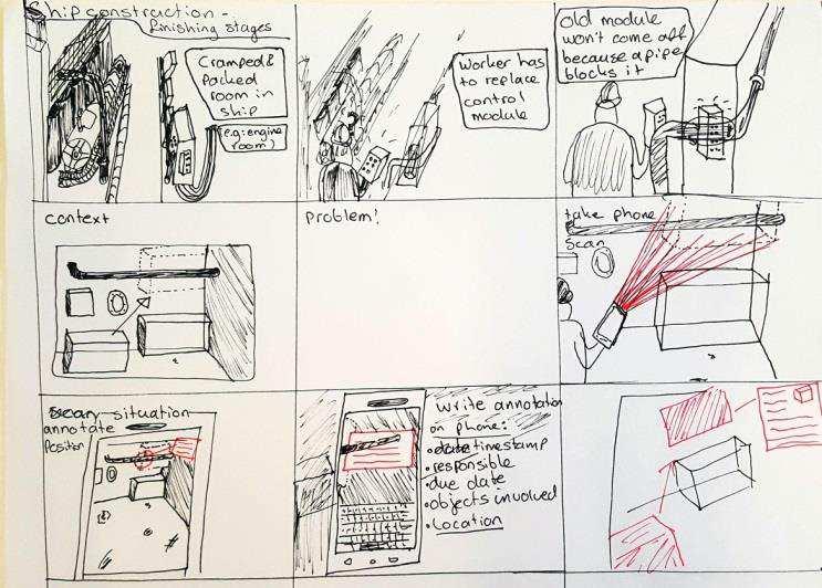
37 9.5 Pictures of the Design process

38 9.5.1 Use-Case scenario used for testing


39 Pictures of the Application The main menu Writing an external report and adding an ADF file Adding markers to fixed locations in 3D

40 9.5.5 Viewing and editing information for each marker (add annotation button highlighted blue)


41 9.5.6 The popup after tapping the new marker button in the lower right corner The popup after pressing delete on the selected marker The popup after pressing the measure button (highlighted blue)


42 9.5.9 Showing the distance to the selected marker The code used to save markers in the example from the Tango SDK The code used to give each marker a unique ID
; This function allows the user to give permission through a popup, to save to an external location.")
43 The complete code used to save a marker 9.6 Code for exporting ADF files AndroidHelper.StartExportADFActivity (); This function allows the user to give permission through a popup, to save to an external location. Once this had been done, the reverse can also be done for importing an ADF, the application uses AndroidHelper.StartImportADFActivity (); to import an ADF from an external location. These functions are part of the Tango namespace in C#. Naming an ADF had to be done through the metadata of an ADF, through AreaDescription.Metadata.metadata = (); Setting the metadata to the result of an input field allows for a user to name an ADF with the keyboard upon saving. 9.7 XML elements of markers In the example in the SDK, The markers were saved through XML, each with three elements, namely: m_type to differentiate between three different coloured markers, m_timestamp to help adjust the position after a loop closure is detected and m_devicetmarker, a transformation matrix containing the position of the marker. To uniquely identify each marker, the XML file for the markers was extended with the element m_id. This allowed to save each marker and upon loading accessing that specific marker. Since the XML was changed, also the save function had to be changed. Each time an ADF was saved, the markers are saved in an XML file with the same name as the ADF. This saving happens in the loop found in appendix The loop takes each marker active in the scene, and saves it in an XML file with each of the three elements specified above. To make sure the m_id is
44 saved for each marker, the save function was edited to save each marker with the element m_id added. The resulting code can be seen in appendix As seen in that code, a check had to be done to ensure that a marker would not be overwritten. Each marker gets an ID, and when a new marker is saved, it is saved with an id that is higher than the current highest ID. This prevents overwriting of markers, which would result in a loss of data. In a similar manner to saving an ID for each marker, the markers were appointed an m_annotation, m_measurebuddy and m_measuredistance variable in the XML and in the save function. This allows the user to annotate markers, and specify what marker to measure the distance to, and store that distance. The resulting save function can be seen in appendix Measuring distances variables As described above, there are also two variables per maker that serve to store distances to other markers. Measuring distances is a possibility in the application since each marker has a specific and accurate location in the 3D scene. There is an example available called Poi t to Poi t hi h enables the user to measure distances. When the markers are placed, measuring distances is relatively simple. It can be done using the function: m_distance = Vector3.Distance(m_startPoint,m_endPoint); Vector3.Distance is a function that calculates the distance between two positions. The variables m_startpoint and m_endpoint are the exact positions of the two markers in between which the distance is measured. The id of the marker at m_endpoint is stored in the variable m_measurebuddy of the marker at the position m_startpoint. This allows measurements to be saved in between sessions, and for them to be exported through the XML file. The measuring process for the user is illustrated with pictures in appendix and

45 9.9 Typical In2CRM problem report
46 9.10 Exported XML 9.11 Notes and remarks of test subjects considering the application 9.12 Form used for the functional test The application Must/Could/Should/Would 1. Work without access to the internet 1.1. App works without Wi-Fi 1.2. Files can be saved offline The users knows how to save a file 2. Generate a reconstruction of a 3D environment and 3D objects D scans can be made with the application 3. Work on a portable device suitable for use inside a ship during reconstruction 3.1. Portability of the device? Durability inside a ship? Be able to understand its position relative to the surroundings using marker less methods 4.1. Markers can be placed 4.2. Markers can be deleted 4.3. Markers can be annotated 4.4. Placed markers stay in position Also after fast movements and shaking 5. Be able to measure distances between several points selected by the user 5.1. The interface regarding the measuring is clear 5.2. The distances are accurate 6. Enable the user to clearly report a problem encountered during construction without the use of a computer 6.1. The place in the interface where reports can be sent is found easily 6.2. A report is made easily 7. Enable the user to read annotations/remarks of other users on a specific 3D position based on their entries in the application

47 7.1. A file can be loaded 7.2. Relocalisation occurs 7.3. Annotations can be found 7.4. Annotations can be edited 8. Have a clear interface that allows easy operation 8.1. Confusing parts of the interface? 9. Be able to function as a proof of concept 9.1. The user understands the aim of the application/system 9.2. The user thinks this application can be useful 10. Be able to function as an addition to current software used The error reports are exported in a friendly format Results of the functional test


48 9.14 Pictures of the testing phase Functional test Use-Case scenario Markers are placed on top of the box that needs to be moved, to measure its size


49 The gap the box has to fit through is measured using different coloured markers


50 The problem is further clarified using markers
![9.15 Error reporting Section 9.16 Code 10 References [2] M. Fiala and G.](/docs-images/71/66019322/images/51-0.jpg "Roth, \"Magic Lens Augmented Reality: Table-top and Augmentorium,\" presented at the ACM SIGGRAPH 2007 posters, San Diego, California, 2007 [3] A. J. Davison, I. D. Reid, N. D. Molton, and O.")
![Stasse, "MonoSLAM: Real-time single camera SLAM," Pattern Analysis and Machine Intelligence, IEEE Transactions on, vol. 29, pp. 1052-1067, 2007 [4]"Cite a Website - Cite This For Me", Gizmodo.](/docs-images/71/66019322/images/51-1.jpg "com, 2017. [Online]. Available: http://gizmodo.com/this-is-how-valve-s-amazing-lighthouse-tracking-technol-1705356768. [Accessed: 30- Mar- 2017]. [5]M. Dissanayake, P. Newman, S. Clark, H.")
51 9.15 Error reporting Section 9.16 Code 10 References [2] M. Fiala and G. Roth, "Magic Lens Augmented Reality: Table-top and Augmentorium," presented at the ACM SIGGRAPH 2007 posters, San Diego, California, 2007 [3] A. J. Davison, I. D. Reid, N. D. Molton, and O. Stasse, "MonoSLAM: Real-time single camera SLAM," Pattern Analysis and Machine Intelligence, IEEE Transactions on, vol. 29, pp , 2007 [4]"Cite a Website - Cite This For Me", Gizmodo.com, [Online]. Available: [Accessed: 30- Mar- 2017]. [5]M. Dissanayake, P. Newman, S. Clark, H. Durrant-Whyte and M. Csorba, "A solution to the simultaneous localization and map building (SLAM) problem", IEEE Transactions on Robotics and Automation, vol. 17, no. 3, pp , 2001.
IoT Wi-Fi- based Indoor Positioning System Using Smartphones
 IoT Wi-Fi- based Indoor Positioning System Using Smartphones Author: Suyash Gupta Abstract The demand for Indoor Location Based Services (LBS) is increasing over the past years as smartphone market expands.
Mixed / Augmented Reality in Action
 Mixed / Augmented Reality in Action AR: Augmented Reality Augmented reality (AR) takes your existing reality and changes aspects of it through the lens of a smartphone, a set of glasses, or even a headset.
IoT. Indoor Positioning with BLE Beacons. Author: Uday Agarwal
 IoT Indoor Positioning with BLE Beacons Author: Uday Agarwal Contents Introduction 1 Bluetooth Low Energy and RSSI 2 Factors Affecting RSSI 3 Distance Calculation 4 Approach to Indoor Positioning 5 Zone
Virtual Reality Based Scalable Framework for Travel Planning and Training
 Virtual Reality Based Scalable Framework for Travel Planning and Training Loren Abdulezer, Jason DaSilva Evolving Technologies Corporation, AXS Lab, Inc. la@evolvingtech.com, jdasilvax@gmail.com Abstract
Head Tracking for Google Cardboard by Simond Lee
 Head Tracking for Google Cardboard by Simond Lee (slee74@student.monash.edu) Virtual Reality Through Head-mounted Displays A head-mounted display (HMD) is a device which is worn on the head with screen
Interior Design with Augmented Reality
 Interior Design with Augmented Reality Ananda Poudel and Omar Al-Azzam Department of Computer Science and Information Technology Saint Cloud State University Saint Cloud, MN, 56301 {apoudel, oalazzam}@stcloudstate.edu
Ubiquitous Positioning: A Pipe Dream or Reality?
 Ubiquitous Positioning: A Pipe Dream or Reality? Professor Terry Moore The University of What is Ubiquitous Positioning? Multi-, low-cost and robust positioning Based on single or multiple users Different
Senion IPS 101. An introduction to Indoor Positioning Systems
 Senion IPS 101 An introduction to Indoor Positioning Systems INTRODUCTION Indoor Positioning 101 What is Indoor Positioning Systems? 3 Where IPS is used 4 How does it work? 6 Diverse Radio Environments
REPORT ON THE CURRENT STATE OF FOR DESIGN. XL: Experiments in Landscape and Urbanism
 REPORT ON THE CURRENT STATE OF FOR DESIGN XL: Experiments in Landscape and Urbanism This report was produced by XL: Experiments in Landscape and Urbanism, SWA Group s innovation lab. It began as an internal
Roadblocks for building mobile AR apps
 Roadblocks for building mobile AR apps Jens de Smit, Layar (jens@layar.com) Ronald van der Lingen, Layar (ronald@layar.com) Abstract At Layar we have been developing our reality browser since 2009. Our
E90 Project Proposal. 6 December 2006 Paul Azunre Thomas Murray David Wright
 E90 Project Proposal 6 December 2006 Paul Azunre Thomas Murray David Wright Table of Contents Abstract 3 Introduction..4 Technical Discussion...4 Tracking Input..4 Haptic Feedack.6 Project Implementation....7
Working towards scenario-based evaluations of first responder positioning systems
 Working towards scenario-based evaluations of first responder positioning systems Jouni Rantakokko, Peter Händel, Joakim Rydell, Erika Emilsson Swedish Defence Research Agency, FOI Royal Institute of Technology,
Robust Positioning for Urban Traffic
 Robust Positioning for Urban Traffic Motivations and Activity plan for the WG 4.1.4 Dr. Laura Ruotsalainen Research Manager, Department of Navigation and positioning Finnish Geospatial Research Institute
idocent: Indoor Digital Orientation Communication and Enabling Navigational Technology
 idocent: Indoor Digital Orientation Communication and Enabling Navigational Technology Final Proposal Team #2 Gordie Stein Matt Gottshall Jacob Donofrio Andrew Kling Facilitator: Michael Shanblatt Sponsor:
Enhancing Shipboard Maintenance with Augmented Reality
 Enhancing Shipboard Maintenance with Augmented Reality CACI Oxnard, CA Dennis Giannoni dgiannoni@caci.com (805) 288-6630 INFORMATION DEPLOYED. SOLUTIONS ADVANCED. MISSIONS ACCOMPLISHED. Agenda Virtual
Agenda Motivation Systems and Sensors Algorithms Implementation Conclusion & Outlook
 Overview of Current Indoor Navigation Techniques and Implementation Studies FIG ww 2011 - Marrakech and Christian Lukianto HafenCity University Hamburg 21 May 2011 1 Agenda Motivation Systems and Sensors
10/18/2010. Focus. Information technology landscape
 Emerging Tools to Enable Construction Engineering Construction Engineering Conference: Opportunity and Vision for Education, Practice, and Research Blacksburg, VA October 1, 2010 A. B. Cleveland, Jr. Senior
Using BIM Geometric Properties for BLE-based Indoor Location Tracking
 Using BIM Geometric Properties for BLE-based Indoor Location Tracking JeeWoong Park a, Kyungki Kim b, Yong K. Cho c, * a School of Civil and Environmental Engineering, Georgia Institute of Technology,
Technical Notes LAND MAPPING APPLICATIONS. Leading the way with increased reliability.
 LAND MAPPING APPLICATIONS Technical Notes Leading the way with increased reliability. Industry-leading post-processing software designed to maximize the accuracy potential of your POS LV (Position and
Years 9 and 10 standard elaborations Australian Curriculum: Digital Technologies
 Purpose The standard elaborations (SEs) provide additional clarity when using the Australian Curriculum achievement standard to make judgments on a five-point scale. They can be used as a tool for: making
Indoor Positioning 101 TECHNICAL)WHITEPAPER) SenionLab)AB) Teknikringen)7) 583)30)Linköping)Sweden)
WHITEPAPER) SenionLab)AB) Teknikringen)7) 583)30)Linköping)Sweden)") Indoor Positioning 101 TECHNICAL)WHITEPAPER) SenionLab)AB) Teknikringen)7) 583)30)Linköping)Sweden) TechnicalWhitepaper)) Satellite-based GPS positioning systems provide users with the position of their
Indoor Positioning 101 TECHNICAL)WHITEPAPER) SenionLab)AB) Teknikringen)7) 583)30)Linköping)Sweden) TechnicalWhitepaper)) Satellite-based GPS positioning systems provide users with the position of their
ReVRSR: Remote Virtual Reality for Service Robots
 ReVRSR: Remote Virtual Reality for Service Robots Amel Hassan, Ahmed Ehab Gado, Faizan Muhammad March 17, 2018 Abstract This project aims to bring a service robot s perspective to a human user. We believe
Cooperative localization (part I) Jouni Rantakokko
 Jouni Rantakokko") Cooperative localization (part I) Jouni Rantakokko Cooperative applications / approaches Wireless sensor networks Robotics Pedestrian localization First responders Localization sensors - Small, low-cost
Cooperative localization (part I) Jouni Rantakokko Cooperative applications / approaches Wireless sensor networks Robotics Pedestrian localization First responders Localization sensors - Small, low-cost
Department of Computer Science and Engineering The Chinese University of Hong Kong. Year Final Year Project
 Digital Interactive Game Interface Table Apps for ipad Supervised by: Professor Michael R. Lyu Student: Ng Ka Hung (1009615714) Chan Hing Faat (1009618344) Year 2011 2012 Final Year Project Department
Educational Augmented Reality Tools: Development, Implementation, and Assessment of Phase I
 Educational Augmented Reality Tools: Development, Implementation, and Assessment of Phase I Dr Konstantinos E. Kakosimos, Dr Ghada Salama, Dr Marcelo Castier & Marcin Kozusznik Texas A&M University at
YOUR PRODUCT IN 3D. Scan and present in Virtual Reality, Augmented Reality, 3D. SCANBLUE.COM
 YOUR PRODUCT IN 3D Scan and present in Virtual Reality, Augmented Reality, 3D. SCANBLUE.COM Foreword Dear customers, for two decades I have been pursuing the vision of bringing the third dimension to the
Limits of a Distributed Intelligent Networked Device in the Intelligence Space. 1 Brief History of the Intelligent Space
 Limits of a Distributed Intelligent Networked Device in the Intelligence Space Gyula Max, Peter Szemes Budapest University of Technology and Economics, H-1521, Budapest, Po. Box. 91. HUNGARY, Tel: +36
Mobile Virtual Reality what is that and how it works? Alexey Rybakov, Senior Engineer, Technical Evangelist at DataArt
 Mobile Virtual Reality what is that and how it works? Alexey Rybakov, Senior Engineer, Technical Evangelist at DataArt alexey.rybakov@dataart.com Agenda 1. XR/AR/MR/MR/VR/MVR? 2. Mobile Hardware 3. SDK/Tools/Development
Tobii Pro VR Integration based on HTC Vive Development Kit Description
 Tobii Pro VR Integration based on HTC Vive Development Kit Description 1 Introduction This document describes the features and functionality of the Tobii Pro VR Integration, a retrofitted version of the
User Guide. PTT Radio Application. Android. Release 8.3
 User Guide PTT Radio Application Android Release 8.3 March 2018 1 Table of Contents 1. Introduction and Key Features... 5 2. Application Installation & Getting Started... 6 Prerequisites... 6 Download...
Augmented and Virtual Reality
 CS-3120 Human-Computer Interaction Augmented and Virtual Reality Mikko Kytö 7.11.2017 From Real to Virtual [1] Milgram, P., & Kishino, F. (1994). A taxonomy of mixed reality visual displays. IEICE TRANSACTIONS
Portfolio. Swaroop Kumar Pal swarooppal.wordpress.com github.com/swarooppal1088
 Portfolio About Me: I am a Computer Science graduate student at The University of Texas at Dallas. I am currently working as Augmented Reality Engineer at Aireal, Dallas and also as a Graduate Researcher
LOCALIZATION WITH GPS UNAVAILABLE
 LOCALIZATION WITH GPS UNAVAILABLE ARES SWIEE MEETING - ROME, SEPT. 26 2014 TOR VERGATA UNIVERSITY Summary Introduction Technology State of art Application Scenarios vs. Technology Advanced Research in
Augmented Reality And Ubiquitous Computing using HCI
 Augmented Reality And Ubiquitous Computing using HCI Ashmit Kolli MS in Data Science Michigan Technological University CS5760 Topic Assignment 2 akolli@mtu.edu Abstract : Direct use of the hand as an input
MEng Project Proposals: Info-Communications
 Proposed Research Project (1): Chau Lap Pui elpchau@ntu.edu.sg Rain Removal Algorithm for Video with Dynamic Scene Rain removal is a complex task. In rainy videos pixels exhibit small but frequent intensity
Indoor Positioning by the Fusion of Wireless Metrics and Sensors
 Indoor Positioning by the Fusion of Wireless Metrics and Sensors Asst. Prof. Dr. Özgür TAMER Dokuz Eylül University Electrical and Electronics Eng. Dept Indoor Positioning Indoor positioning systems (IPS)
Aerospace Sensor Suite
 Aerospace Sensor Suite ECE 1778 Creative Applications for Mobile Devices Final Report prepared for Dr. Jonathon Rose April 12 th 2011 Word count: 2351 + 490 (Apper Context) Jin Hyouk (Paul) Choi: 998495640
Indoor navigation with smartphones
 Indoor navigation with smartphones REinEU2016 Conference September 22 2016 PAVEL DAVIDSON Outline Indoor navigation system for smartphone: goals and requirements WiFi based positioning Application of BLE
B L E N e t w o r k A p p l i c a t i o n s f o r S m a r t M o b i l i t y S o l u t i o n s
 B L E N e t w o r k A p p l i c a t i o n s f o r S m a r t M o b i l i t y S o l u t i o n s A t e c h n i c a l r e v i e w i n t h e f r a m e w o r k o f t h e E U s Te t r a m a x P r o g r a m m
Exploring Pedestrian Bluetooth and WiFi Detection at Public Transportation Terminals
 Exploring Pedestrian Bluetooth and WiFi Detection at Public Transportation Terminals Neveen Shlayan 1, Abdullah Kurkcu 2, and Kaan Ozbay 3 November 1, 2016 1 Assistant Professor, Department of Electrical
Cooperative navigation (part II)
") Cooperative navigation (part II) An example using foot-mounted INS and UWB-transceivers Jouni Rantakokko Aim Increased accuracy during long-term operations in GNSS-challenged environments for - First responders
Cooperative navigation (part II) An example using foot-mounted INS and UWB-transceivers Jouni Rantakokko Aim Increased accuracy during long-term operations in GNSS-challenged environments for - First responders
Apple ARKit Overview. 1. Purpose. 2. Apple ARKit. 2.1 Overview. 2.2 Functions
 Apple ARKit Overview 1. Purpose In the 2017 Apple Worldwide Developers Conference, Apple announced a tool called ARKit, which provides advanced augmented reality capabilities on ios. Augmented reality
Technical Notes FOR MARINE MAPPING APPLICATIONS. Leading the way with increased reliability.
 FOR MARINE MAPPING APPLICATIONS Technical Notes Leading the way with increased reliability. Industry-leading post-processing software designed to maximize the accuracy potential of your POS MV (Position
preface Motivation Figure 1. Reality-virtuality continuum (Milgram & Kishino, 1994) Mixed.Reality Augmented. Virtuality Real...
 Mixed.Reality Augmented. Virtuality Real...") v preface Motivation Augmented reality (AR) research aims to develop technologies that allow the real-time fusion of computer-generated digital content with the real world. Unlike virtual reality (VR)
v preface Motivation Augmented reality (AR) research aims to develop technologies that allow the real-time fusion of computer-generated digital content with the real world. Unlike virtual reality (VR)
A Step Forward in Virtual Reality. Department of Electrical and Computer Engineering
 A Step Forward in Virtual Reality Team Step Ryan Daly Electrical Engineer Jared Ricci Electrical Engineer Joseph Roberts Electrical Engineer Steven So Electrical Engineer 2 Motivation Current Virtual Reality
BoBoiBoy Interactive Holographic Action Card Game Application
 UTM Computing Proceedings Innovations in Computing Technology and Applications Volume 2 Year: 2017 ISBN: 978-967-0194-95-0 1 BoBoiBoy Interactive Holographic Action Card Game Application Chan Vei Siang
Localization in Wireless Sensor Networks
 Localization in Wireless Sensor Networks Part 2: Localization techniques Department of Informatics University of Oslo Cyber Physical Systems, 11.10.2011 Localization problem in WSN In a localization problem
Product Requirements Document
 Product Requirements Document Team: Under Construction Authors: Michael Radbel (Lead), Matthew Ruth (Scribe), Maneesh Karipineni, Ilyne Han, Yun Suk Chang Project Name: vmemo Revision History Version Number
SPIDERMAN VR. Adam Elgressy and Dmitry Vlasenko
 SPIDERMAN VR Adam Elgressy and Dmitry Vlasenko Supervisors: Boaz Sternfeld and Yaron Honen Submission Date: 09/01/2019 Contents Who We Are:... 2 Abstract:... 2 Previous Work:... 3 Tangent Systems & Development
Kinect Interface for UC-win/Road: Application to Tele-operation of Small Robots
 Kinect Interface for UC-win/Road: Application to Tele-operation of Small Robots Hafid NINISS Forum8 - Robot Development Team Abstract: The purpose of this work is to develop a man-machine interface for
SAP Dynamic Edge Processing IoT Edge Console - Administration Guide Version 2.0 FP01
 SAP Dynamic Edge Processing IoT Edge Console - Administration Guide Version 2.0 FP01 Table of Contents ABOUT THIS DOCUMENT... 3 Glossary... 3 CONSOLE SECTIONS AND WORKFLOWS... 5 Sensor & Rule Management...
User Guide: PTT Application - Android. User Guide. PTT Application. Android. Release 8.3
 User Guide PTT Application Android Release 8.3 March 2018 1 1. Introduction and Key Features... 6 2. Application Installation & Getting Started... 7 Prerequisites... 7 Download... 8 First-time Activation...
Marco Cavallo. Merging Worlds: A Location-based Approach to Mixed Reality. Marco Cavallo Master Thesis Presentation POLITECNICO DI MILANO
 Marco Cavallo Merging Worlds: A Location-based Approach to Mixed Reality Marco Cavallo Master Thesis Presentation POLITECNICO DI MILANO Introduction: A New Realm of Reality 2 http://www.samsung.com/sg/wearables/gear-vr/
A Turnkey Weld Inspection Solution Combining PAUT & TOFD
 A Turnkey Weld Inspection Solution Combining PAUT & TOFD INTRODUCTION With the recent evolutions of the codes & standards, the replacement of conventional film radiography with advanced ultrasonic testing
2D Floor-Mapping Car
 CDA 4630 Embedded Systems Final Report Group 4: Camilo Moreno, Ahmed Awada ------------------------------------------------------------------------------------------------------------------------------------------
best practice guide Ruckus SPoT Best Practices SOLUTION OVERVIEW AND BEST PRACTICES FOR DEPLOYMENT
 best practice guide Ruckus SPoT Best Practices SOLUTION OVERVIEW AND BEST PRACTICES FOR DEPLOYMENT Overview Since the mobile device industry is alive and well, every corner of the ever-opportunistic tech
Intro to Virtual Reality (Cont)
") Lecture 37: Intro to Virtual Reality (Cont) Computer Graphics and Imaging UC Berkeley CS184/284A Overview of VR Topics Areas we will discuss over next few lectures VR Displays VR Rendering VR Imaging CS184/284A
Lecture 37: Intro to Virtual Reality (Cont) Computer Graphics and Imaging UC Berkeley CS184/284A Overview of VR Topics Areas we will discuss over next few lectures VR Displays VR Rendering VR Imaging CS184/284A
Real Time Indoor Tracking System using Smartphones and Wi-Fi Technology
 International Journal for Modern Trends in Science and Technology Volume: 03, Issue No: 08, August 2017 ISSN: 2455-3778 http://www.ijmtst.com Real Time Indoor Tracking System using Smartphones and Wi-Fi
The Fastest, Easiest, Most Accurate Way To Compare Parts To Their CAD Data
 210 Brunswick Pointe-Claire (Quebec) Canada H9R 1A6 Web: www.visionxinc.com Email: info@visionxinc.com tel: (514) 694-9290 fax: (514) 694-9488 VISIONx INC. The Fastest, Easiest, Most Accurate Way To Compare
A SURVEY OF MOBILE APPLICATION USING AUGMENTED REALITY
 Volume 117 No. 22 2017, 209-213 ISSN: 1311-8080 (printed version); ISSN: 1314-3395 (on-line version) url: http://www.ijpam.eu ijpam.eu A SURVEY OF MOBILE APPLICATION USING AUGMENTED REALITY Mrs.S.Hemamalini
A Step Forward in Virtual Reality. Department of Electrical and Computer Engineering
 A Step Forward in Virtual Reality Team Step Ryan Daly Electrical Engineer Jared Ricci Electrical Engineer Joseph Roberts Electrical Engineer Steven So Electrical Engineer 2 Motivation Current Virtual Reality
USTGlobal. VIRTUAL AND AUGMENTED REALITY Ideas for the Future - Retail Industry
 USTGlobal VIRTUAL AND AUGMENTED REALITY Ideas for the Future - Retail Industry UST Global Inc, August 2017 Table of Contents Introduction 3 Focus on Shopping Experience 3 What we can do at UST Global 4
Sponsored by. Nisarg Kothari Carnegie Mellon University April 26, 2011
 Sponsored by Nisarg Kothari Carnegie Mellon University April 26, 2011 Motivation Why indoor localization? Navigating malls, airports, office buildings Museum tours, context aware apps Augmented reality
Push-to-talk ios User Guide (v8.0)
") Push-to-talk ios User Guide (v8.0) PTT 8.0 ios - Table of Contents 1 Activating PTT on your ios device... 4 How to activate PTT on your Android Smartphone... 4 How to Logout and Login to the PTT Service...
Push-to-talk ios User Guide (v8.0) PTT 8.0 ios - Table of Contents 1 Activating PTT on your ios device... 4 How to activate PTT on your Android Smartphone... 4 How to Logout and Login to the PTT Service...
ADVANCED WHACK A MOLE VR
 ADVANCED WHACK A MOLE VR Tal Pilo, Or Gitli and Mirit Alush TABLE OF CONTENTS Introduction 2 Development Environment 3 Application overview 4-8 Development Process - 9 1 Introduction We developed a VR
Indoor Floorplan with WiFi Coverage Map Android Application
 Indoor Floorplan with WiFi Coverage Map Android Application Zeying Xin Electrical Engineering and Computer Sciences University of California at Berkeley Technical Report No. UCB/EECS-2013-114 http://www.eecs.berkeley.edu/pubs/techrpts/2013/eecs-2013-114.html
Higher National Unit specification: general information
 Higher National Unit specification: general information Unit code: H17R 35 Superclass: CB Publication date: March 2012 Source: Scottish Qualifications Authority Version: 01 Unit purpose This Unit is designed
Annotation Overlay with a Wearable Computer Using Augmented Reality
 Annotation Overlay with a Wearable Computer Using Augmented Reality Ryuhei Tenmokuy, Masayuki Kanbara y, Naokazu Yokoya yand Haruo Takemura z 1 Graduate School of Information Science, Nara Institute of
EnSight in Virtual and Mixed Reality Environments
 CEI 2015 User Group Meeting EnSight in Virtual and Mixed Reality Environments VR Hardware that works with EnSight Canon MR Oculus Rift Cave Power Wall Canon MR MR means Mixed Reality User looks through
Indoor Positioning Systems WLAN Positioning
 Praktikum Mobile und Verteilte Systeme Indoor Positioning Systems WLAN Positioning Prof. Dr. Claudia Linnhoff-Popien Florian Dorfmeister, Chadly Marouane, Kevin Wiesner http://www.mobile.ifi.lmu.de Sommersemester
A 3D Ubiquitous Multi-Platform Localization and Tracking System for Smartphones. Seyyed Mahmood Jafari Sadeghi
 A 3D Ubiquitous Multi-Platform Localization and Tracking System for Smartphones by Seyyed Mahmood Jafari Sadeghi A thesis submitted in conformity with the requirements for the degree of Doctor of Philosophy
MOBILE COMPUTING 1/29/18. Cellular Positioning: Cell ID. Cellular Positioning - Cell ID with TA. CSE 40814/60814 Spring 2018
 MOBILE COMPUTING CSE 40814/60814 Spring 2018 Cellular Positioning: Cell ID Open-source database of cell IDs: opencellid.org Cellular Positioning - Cell ID with TA TA: Timing Advance (time a signal takes
A Mashup of Techniques to Create Reference Architectures
 A Mashup of Techniques to Create Reference Architectures Software Engineering Institute Carnegie Mellon University Pittsburgh, PA 15213 Rick Kazman, John McGregor Copyright 2012 Carnegie Mellon University.
The Technologies behind a Context-Aware Mobility Solution
 The Technologies behind a Context-Aware Mobility Solution Introduction The concept of using radio frequency techniques to detect or track entities on land, in space, or in the air has existed for many
What was the first gestural interface?
 stanford hci group / cs247 Human-Computer Interaction Design Studio What was the first gestural interface? 15 January 2013 http://cs247.stanford.edu Theremin Myron Krueger 1 Myron Krueger There were things
Location Discovery in Sensor Network
 Location Discovery in Sensor Network Pin Nie Telecommunications Software and Multimedia Laboratory Helsinki University of Technology niepin@cc.hut.fi Abstract One established trend in electronics is micromation.
User Guide. PTT Radio Application. ios. Release 8.3
 User Guide PTT Radio Application ios Release 8.3 March 2018 1 Table of Contents 1. Introduction and Key Features... 5 2. Application Installation & Getting Started... 6 Prerequisites... 6 Download... 6
Draft TR: Conceptual Model for Multimedia XR Systems
 Document for IEC TC100 AGS Draft TR: Conceptual Model for Multimedia XR Systems 25 September 2017 System Architecture Research Dept. Hitachi, LTD. Tadayoshi Kosaka, Takayuki Fujiwara * XR is a term which
From Room Instrumentation to Device Instrumentation: Assessing an Inertial Measurement Unit for Spatial Awareness
 From Room Instrumentation to Device Instrumentation: Assessing an Inertial Measurement Unit for Spatial Awareness Alaa Azazi, Teddy Seyed, Frank Maurer University of Calgary, Department of Computer Science
Input devices and interaction. Ruth Aylett
 Input devices and interaction Ruth Aylett Contents Tracking What is available Devices Gloves, 6 DOF mouse, WiiMote Why is it important? Interaction is basic to VEs We defined them as interactive in real-time
Smartphone Positioning and 3D Mapping Indoors
 Smartphone Positioning and 3D Mapping Indoors Ruizhi Chen Wuhan University Oct. 4, 2018, Delft Adding a Smart LIFE to 3D People spend 80% of their time indoors When People Communicates to a Robot, We Need
Enhanced Push-to-Talk Application for Android
 AT&T Business Mobility Enhanced Push-to-Talk Application for Android Land Mobile Radio (LMR) Version Release 8.3 Table of Contents Introduction and Key Features 2 Application Installation & Getting Started
Hardware-free Indoor Navigation for Smartphones
 Hardware-free Indoor Navigation for Smartphones 1 Navigation product line 1996-2015 1996 1998 RTK OTF solution with accuracy 1 cm 8-channel software GPS receiver 2004 2007 Program prototype of Super-sensitive
Audio Output Devices for Head Mounted Display Devices
 Technical Disclosure Commons Defensive Publications Series February 16, 2018 Audio Output Devices for Head Mounted Display Devices Leonardo Kusumo Andrew Nartker Stephen Schooley Follow this and additional
Range Sensing strategies
 Range Sensing strategies Active range sensors Ultrasound Laser range sensor Slides adopted from Siegwart and Nourbakhsh 4.1.6 Range Sensors (time of flight) (1) Large range distance measurement -> called
User Guide: PTT Radio Application - ios. User Guide. PTT Radio Application. ios. Release 8.3
 User Guide PTT Radio Application ios Release 8.3 December 2017 Table of Contents Contents 1. Introduction and Key Features... 5 2. Application Installation & Getting Started... 6 Prerequisites... 6 Download...
Video Injection Methods in a Real-world Vehicle for Increasing Test Efficiency
 DEVELOPMENT SIMUL ATION AND TESTING Video Injection Methods in a Real-world Vehicle for Increasing Test Efficiency IPG Automotive AUTHORS For the testing of camera-based driver assistance systems under
Knowledge Acquisition and Representation in Facility Management
 2016 International Conference on Computational Science and Computational Intelligence Knowledge Acquisition and Representation in Facility Management Facility Management with Semantic Technologies and
MECHANICAL DESIGN LEARNING ENVIRONMENTS BASED ON VIRTUAL REALITY TECHNOLOGIES
 INTERNATIONAL CONFERENCE ON ENGINEERING AND PRODUCT DESIGN EDUCATION 4 & 5 SEPTEMBER 2008, UNIVERSITAT POLITECNICA DE CATALUNYA, BARCELONA, SPAIN MECHANICAL DESIGN LEARNING ENVIRONMENTS BASED ON VIRTUAL
Markerless 3D Gesture-based Interaction for Handheld Augmented Reality Interfaces
 Markerless 3D Gesture-based Interaction for Handheld Augmented Reality Interfaces Huidong Bai The HIT Lab NZ, University of Canterbury, Christchurch, 8041 New Zealand huidong.bai@pg.canterbury.ac.nz Lei
Scheduling and Motion Planning of irobot Roomba
 Scheduling and Motion Planning of irobot Roomba Jade Cheng yucheng@hawaii.edu Abstract This paper is concerned with the developing of the next model of Roomba. This paper presents a new feature that allows
Integrated Positioning The Challenges New technology More GNSS satellites New applications Seamless indoor-outdoor More GNSS signals personal navigati
 Integrated Indoor Positioning and Navigation Professor Terry Moore Professor of Satellite Navigation Nottingham Geospatial Institute The University of Nottingham Integrated Positioning The Challenges New
GESTURE RECOGNITION SOLUTION FOR PRESENTATION CONTROL
 GESTURE RECOGNITION SOLUTION FOR PRESENTATION CONTROL Darko Martinovikj Nevena Ackovska Faculty of Computer Science and Engineering Skopje, R. Macedonia ABSTRACT Despite the fact that there are different
A Hybrid Immersive / Non-Immersive
 A Hybrid Immersive / Non-Immersive Virtual Environment Workstation N96-057 Department of the Navy Report Number 97268 Awz~POved *om prwihc?e1oaa Submitted by: Fakespace, Inc. 241 Polaris Ave. Mountain
WhereAReYou? An Offline Bluetooth Positioning Mobile Application
 WhereAReYou? An Offline Bluetooth Positioning Mobile Application SPCL-2013 Project Report Daniel Lujan Villarreal dluj@itu.dk ABSTRACT The increasing use of social media and the integration of location
Chapter 1 - Introduction
 1 "We all agree that your theory is crazy, but is it crazy enough?" Niels Bohr (1885-1962) Chapter 1 - Introduction Augmented reality (AR) is the registration of projected computer-generated images over
EOS 80D (W) Wireless Function Instruction Manual ENGLISH INSTRUCTION MANUAL
 Wireless Function Instruction Manual ENGLISH INSTRUCTION MANUAL") EOS 80D (W) Wireless Function Instruction Manual ENGLISH INSTRUCTION MANUAL Introduction What You Can Do Using the Wireless Functions This camera s wireless functions let you perform a range of tasks wirelessly,
EOS 80D (W) Wireless Function Instruction Manual ENGLISH INSTRUCTION MANUAL Introduction What You Can Do Using the Wireless Functions This camera s wireless functions let you perform a range of tasks wirelessly,
A system for indoor positioning using ultra-wideband technology
 A system for indoor positioning using ultra-wideband technology Master s thesis in Embedded Electronic System Design SEBASTIAN DÄDEBY JOAKIM HESSELGREN Department of Computer Science and Engineering CHALMERS
Marvelmind Indoor Navigation System Operating Manual V2015_09_21
 Marvelmind Indoor Navigation System Operating Manual V2015_09_21 Table of Contents 1) Executive summary...3 2) Basics of the system...4 3) What is in the box...8 4) Technical Specifications...9 Table:
2.4GHz vs. Sub-GHz Markets, Applications & Key Decisions
 www.silabs.com 2.4GHz vs. Sub-GHz Markets, Applications & Key Decisions Overview Many customers are trying to decide between 2.4 GHz or sub-ghz This presentation will define the key factors impacting a