Street Canyon Tool. User Guide CERC
|
|
|
- Justin Nicholson
- 5 years ago
- Views:
Transcription


1 Street Canyon Tool User Guide CERC
2
3 ADMS Street Canyon Tool Version 2.0 User Guide August 2018 Cambridge Environmental Research Consultants Ltd. 3, King s Parade Cambridge CB2 1SJ UK Telephone: +44 (0) Facsimile: +44 (0) help@cerc.co.uk Website:
4
5 Introduction Contents SECTION 1 Introduction About the Street Canyon Tool Features Requirements About this user guide... 1 SECTION 2 Using the Street Canyon Tool Installing the Street Canyon Tool Running the Street Canyon Tool Create Street Canyon File Tool Input road layer Road name field Primary building layer Building height field Output CSV file Output road shapefile Additional building layers Settings Version Information Running the Tool Monitoring Progress Viewing the results Output CSV file Road Layer shapefile Display Canyon Widths Tool Road layer Canyon width (left) Canyon width (right) Output shapefile Version Information Running the Tool 12 SECTION 3 Technical Summary The Advanced Canyon module input data The Create Street Canyon File tool Locating buildings that affect a road source Calculating the canyon width Calculating the Advanced Canyon module parameters 20 Street Canyon Tool User Guide Page i
6 Introduction Street Canyon Tool User Guide Page ii
7 SECTION 1 - Introduction SECTION 1 Introduction 1.1 About the Street Canyon Tool The Street Canyon Tool generates street canyon data for use with the ADMS-Urban Advanced Canyon module, including canyon width, length and height. The Street Canyon Tool runs inside ArcGIS and uses building and road datasets to calculate Advanced Canyon parameters. 1.2 Features The Street Canyon Tool can be used to calculate the following for each road: Canyon heights (maximum, mean and minimum) Canyon widths Canyon length The data is available as a new shapefile based on the input road layer, with new fields for the data and in a *.csv format suitable for use with the ADMS-Urban module. 1.3 Requirements The Street Canyon Tool toolbox requires the following: A copy of ESRI ArcGIS (Version 10.1 or later) 1.4 About this user guide This Street Canyon Tool User Guide is a manual describing how to use the Street Canyon Tool. To make this manual simpler to use, certain conventions have been followed with regard to layout and style. Canyon Height toolbox interface controls are shown in Arial font, e.g. click on Generate Report. Keyboard inputs are shown in bold, e.g. press Enter. Directory and file names are shown in italics, e.g. *.nc. Table and figure references are shown in bold, e.g. see Figure 3.1 Street Canyon Tool User Guide Page 1
8 SECTION 1 - Introduction Street Canyon Tool User Guide Page 2

9 SECTION 2 - Using the Street Canyon Tool SECTION 2 Using the Street Canyon Tool 2.1 Installing the Street Canyon Tool To install the Street Canyon Tool, simply copy the contents of the install directory to a directory with full privileges on your machine. From the Start menu, open ArcCatalog. Open the ArcToolbox window ( on the toolbar), right-click on the ArcToolbox window (see Figure 1) and select Add Toolbox... Figure 1 - The ArcToolbox Navigate to the folder containing the Street Canyon Tool files and select StreetCanyon.pyt. Street Canyon Tools should now appear in the ArcToolbox in ArcCatalog and also in ArcMap, as shown in Figure 2 below. The toolbox has two tools, named Create Street Canyon File and Display Canyon Widths. Street Canyon Tool User Guide Page 3

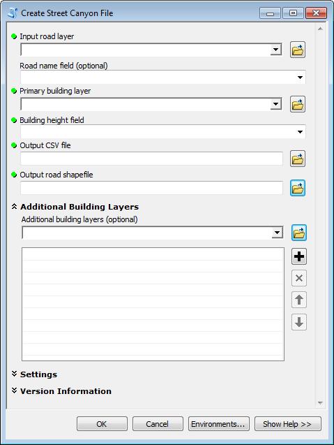
10 SECTION 2 - Using the Street Canyon Tool Figure 2 - The Street Canyon Tools toolbox 2.2 Running the Street Canyon Tool Once Street Canyon Tools has been added to the ArcGIS ArcToolbox window (refer to Section 2.1 Installing the Street Canyon Tool) it can be used by clicking on Street Canyon Tools to reveal the Create Street Canyon File tool. The user is advised (though not required) to load the required roads and building shapefiles into ArcGIS before running the tool. The input layers must be shapefiles, not (for example) geodatabase layers. All input shapefiles must be in the same coordinate system. This must be a projected coordinate system with units of metres. Also the input layers must not have been created from ArcGIS's "Make Feature Layer" tool with the "Use Ratio Policy" option. 2.3 Create Street Canyon File Tool The main screen, shown in Figure 3, appears on clicking on the Create Street Canyon File tool in the Street Canyon Tools toolbox. Each of the features and buttons are described below. Street Canyon Tool User Guide Page 4

11 SECTION 2 - Using the Street Canyon Tool In the Create Street Canyon File main screen, click on Show Help >> to display information relating to each input. Figure 3 The main screen Input road layer The Input road layer is the shapefile containing the road geometry for each road feature. The road layer can be selected by using the dropdown, if the layer is already loaded in ArcGIS, or by clicking the Browse button to navigate to and select the shapefile. The Input road layer shapefile must use a coordinate system with units of metres. If specific features in this shapefile are selected in ArcGIS, the Create Street Canyon Tool will output the results for these specific features only. If no features are selected, the Create Street Canyon Tool will output results for all features. Street Canyon Tool User Guide Page 5
12 SECTION 2 - Using the Street Canyon Tool Road name field The Road name field is the field in the Road Layer storing the name of the road. The road names in the Road name field must match those in the ADMS-Urban *.upl file Primary building layer The Primary building layer is a shapefile containing building geometry and building height information for each building feature. The primary building layer can be selected by using the dropdown, if the layer is already loaded in ArcGIS, or by clicking the Browse button to navigate to and select the shapefile. The Primary building layer shapefile must use a coordinate system with units of metres. The tool may run faster if buildings with height lower than 1m are manually deleted before running the tool Building height field The Building height field is the field in the Primary building layer which stores the building height information for each building feature. The building height should be the height above ground level and should be in metres Output CSV file The Output CSV file defines the location for the *.csv results, for use with the ADMS-Urban Advanced Canyon module Output road shapefile The Output road shapefile defines the location for the *.shp results. This shapefile contains the attributes from the input shapefile as well as the calculated canyon statistics Additional building layers The Additional building layers section enables users to provide extra building layers. Additional building layers may be required if the building data is provided in tiles, or if there are multiple layers for different building types. Street Canyon Tool User Guide Page 6

 must be in the same coordinate system as the Primary building layer (refer to Section 2.3.")
13 SECTION 2 - Using the Street Canyon Tool Figure 4 The Additional Building Layers section Additional building layers Additional building layers can be selected by using the dropdown, if the layers are already loaded in ArcGIS, or by using the Browse button to navigate to and select the shapefile. Layers can be removed from the list by using the button to the right of the list. The Additional building layers shapefile(s) must be in the same coordinate system as the Primary building layer (refer to Section 2.3.3) and must have the same name for the Building height field Settings Figure 5 The Settings section Appropriate values for all of the settings must be determined for the cityscape. A degree of experimentation may be necessary. Section gives some values used by CERC in recent case studies. Street Canyon Tool User Guide Page 7
 and Building distance tolerance (metres) These two settings define a tolerance buffer beyond the base building.")
14 SECTION 2 - Using the Street Canyon Tool Building distance tolerance (proportion) and Building distance tolerance (metres) These two settings define a tolerance buffer beyond the base building. Any buildings, or building sections, in this buffer will be included in the canyon height calculations. The total tolerance distance is the sum of a proportion of the minimum distance (from the road centreline to the base building) and a constant distance. The Building distance tolerance (proportion) defines the proportion used. The Building distance tolerance (metres) defines the constant component of the total tolerance distance. Figure 6 illustrates this. Section 3.2 explains the calculation in detail. Figure 6 Total tolerance distance. The blue rectangle is the tolerance buffer Precision mode The Precision mode defines the precision of the results. In EMIT mode, vertices and results are rounded to the nearest metre. In ADMS mode they are rounded to the nearest centimetre. These are set to match the requirements of the EMIT and ADMS models Target minimum proportion of road with buildings The Target minimum proportion of road with buildings defines the goal used when the algorithm chooses the base building (see Technical Summary). The proportion of road with buildings is the ratio between the canyon coverage and the canyon length, e.g. 0.5 would expect 50% or more of the canyon's length to contain buildings. In cases where some buildings on a road side are offset from others, larger values of this parameter may cause small buildings near the road centreline to be ignored, leading to the calculation of wider canyons that have greater canyon coverage (see Figure 12) Maximum distance to the nearest building The Maximum distance to the nearest building defines the distance from the road centreline the tool will search to find suitable base buildings. If there are no buildings within this distance, the canyon statistics for this side of the road will be zero. Street Canyon Tool User Guide Page 8
15 SECTION 2 - Using the Street Canyon Tool Example settings Appropriate values must be determined for the cityscape being modelled. Table 1 below shows values used by CERC for some recent case studies. Case study: London Hong Kong Building distance tolerance (proportion) Building distance tolerance (metres) Target minimum proportion of road with buildings Maximum distance to the nearest building Table 1 Example setting values Version Information The Version Information section contains information about the version of the tool. This information should be included in any correspondence with CERC Running the Tool Clicking OK will run the tool. The ArcMap window will display scrolling text at the bottom right, indicating that the tool is running. 2.4 Monitoring Progress In ArcMap, under the Geoprocessing menu, open the Results window. The top entry in the Current Session will be the tool in progress. The Inputs menu gives details of the tool inputs selected. The Messages menu displays progress messages from the tool. It is possible to cancel the tool run, by right-clicking on the tool in progress and clicking Cancel. Street Canyon Tool User Guide Page 9

16 SECTION 2 - Using the Street Canyon Tool Figure 7 The Results window in ArcGIS Geoprocessing 2.5 Viewing the results Output CSV file The results will be available in the *.csv file selected in Output CSV file, as shown in Figure 8 Figure 8 Example *.csv output The results include the headers and parameters required to use the file with the ADMS-Urban Advanced Canyon option without any editing Road Layer shapefile The resulting street canyon parameters will be added to the output road shapefile. The results can be read from the Attributes Table, as presented in Figure 9. Alternatively, the shapefile data can be viewed in the map by using the Identify tool Road Layer. on any of the road features in the The Display Canyon Widths tool can also be used, refer to Section 2.6 for more information. Street Canyon Tool User Guide Page 10


17 SECTION 2 - Using the Street Canyon Tool Figure 9 Example results in the Output road shapefile Attribute Table 2.6 Display Canyon Widths Tool The Display Canyon Widths tool provides a visual representation of the results of the Street Canyon Tool. The main screen, shown in Figure 10, appears on clicking on the Display Canyon Widths tool in Street Canyon Tools. Each of the features and buttons are described below. In the Display Canyon Widths tool main screen, click on Show Help >> to display information Figure 10 The main Display Canyon Widths screen Street Canyon Tool User Guide Page 11
18 SECTION 2 - Using the Street Canyon Tool Road layer The Road layer is the shapefile containing the results of the Create Street Canyon File tool. The road layer can be selected by using the dropdown, if the layer is already loaded in ArcGIS, or by clicking the Browse button to navigate to and select the shapefile. If specific features in this shapefile are selected in ArcGIS, the Display Canyon Widths tool will output the results for these specific features only. If no features are selected, the Display Canyon Widths tool will output results for all features Canyon width (left) Canyon width (left) is the field in the shapefile storing the canyon width for the left hand side of the road. When using a shapefile containing the results of the Street Canyon tool, this field will be c_width_l Canyon width (right) Canyon width (right) is the field in the shapefile storing the canyon width for the right hand side of the road. When using a shapefile containing the results of the Street Canyon tool, this field will be c_width_r Output shapefile The Output shapefile defines the location for the *.shp containing the canyon width polygons Version Information The Version Information section contains information about the version of the tool. This information should be included in any correspondence with CERC Running the Tool Clicking OK will run the tool. The ArcMap window will display scrolling text at the bottom right, indicating that the tool is running. Street Canyon Tool User Guide Page 12

19 SECTION 2 - Using the Street Canyon Tool Figure 11 Example Display Canyon Width output Street Canyon Tool User Guide Page 13
20 SECTION 2 - Using the Street Canyon Tool Street Canyon Tool User Guide Page 14
21 SECTION 3 - Technical Summary SECTION 3 Technical Summary This section provides a technical summary of the Street Canyon Tools toolbox. User-defined inputs to the tool are described in Section 2 of this User Guide. The Create Street Canyon File tool generates a *.csv format file that can be used directly with the Advanced Canyon module in ADMS-Urban. The file outputs all of the required headers, together with averaged canyon parameter data, for each road feature in the Input road layer. A shapefile can also be output from the tool, containing the same information, which can be viewed spatially in GIS software. The Display Canyon Width tool can be used to visualise the canyon widths in ArcGIS. 3.1 The Advanced Canyon module input data The parameters required by the ADMS-Urban Advanced Canyon module are described in Table 2. A schematic of the parameters is also presented in Figure 12, with the associated shapefile variable names. Variable name Variable name in *.csv file in shapefile Units Description ID ID - Source identifier (optional) Name Name - Source (road) name X1, Y1 X1, Y1 m x and y coordinates of first vertex (start) X2, Y2 X2, Y2 m x and y coordinates of second vertex (end of first segment) width_l, width_r c_width_l, Distance from road centreline to canyon wall on m c_width_r left and right sides respectively avgheight_l, c_height_l, Average canyon height on left and right sides m avgheight_r c_height_r respectively minheight_l, c_minh_l, Minimum canyon height on left and right sides m minheight_r c_minh_r respectively maxheight_l, c_maxh_l, Maximum canyon height on left and right sides m maxheight_r c_maxh_r respectively canyonlength_l, c_length_l, Length of canyon on left and right sides m canyonlength_r c_length_r respectively endlength_l, c_start_l, Distance from start of road to first building in m endlength_r c_start_r canyon on left and right sides respectively buildlength_l, c_cover_l, Length of buildings in canyon on left and right m buildlength_r c_cover_r sides respectively Table 2 ADMS-Urban Advanced Canyon module input parameters, which are output by the Street Canyon Tool Street Canyon Tool User Guide Page 15
.")
22 SECTION 3 - Technical Summary Figure 12 Canyon height results (left hand side, as given in the Road Layer shapefile) 3.2 The Create Street Canyon File tool Locating buildings that affect a road source The Create Street Canyon File tool first identifies all building sections that may affect the road. These are the building sections within a tolerance buffer. The tolerance buffer is calculated using the road and building geometry and the tolerance settings defined by the user (see Section 2.3.8). The left and right sides of the canyon are assigned according to the orientation of the first and second vertices, where the first vertex represents the start and the second vertex represents the end of the first straight-line segment of the road. The left and right side calculations are carried out independently. Note that the order of the vertices will be checked against the road source data in ADMS-Urban, based on the road name. For each road and each side of the road, the Create Street Canyon File tool: Finds a suitable base building close to the road on that side for any road segment. The base building will be partially or completely within the Maximum distance to the nearest building to the road. If the Target minimum proportion of road with buildings is set to 0.0, the base building will be the nearest building to the road. For other values of Target minimum proportion of road with buildings, the selected base building may be further away in order to achieve better coverage. It selects the nearest building that satisfies the target minimum proportion, or if no building satisfies that proportion, it selects the building that gives the highest coverage. Street Canyon Tool User Guide Page 16
, and b is the user-editable Building distance tolerance (metres).")
23 SECTION 3 - Technical Summary Calculates a total tolerance distance: where, x is the minimum distance from the base building to the road centreline, f is the user-editable Building distance tolerance (proportion), and b is the user-editable Building distance tolerance (metres). Determines a tolerance buffer for each road segment: this is a rectangle beyond the base building and within the total tolerance distance from the base building, perpendicular to the road centreline (see Figure 15). Parts of buildings outside the tolerance buffer are not included in the calculations. Stores the height and length of each building face as projected onto the road centreline, as illustrated in Figure 13. Minimum distance to building Total tolerance distance Road centreline Figure 13 Example total tolerance distance for the right hand side of a road feature. The red outline is the tolerance buffer. The yellow rectangle is the base building. Street Canyon Tool User Guide Page 17
24 SECTION 3 - Technical Summary When two or more buildings or buildings of varying height are found in the same location, the height and length of each part of the building(s) is apportioned into multiple segments. The approach is illustrated in Figure 14. z length a y x height a length b x length a length b height b road feature Building face Figure 14 Illustration of the approach taken with varying building height The following limitations apply: A road with no adjacent buildings will be assigned values of 0 for all of the Advanced Canyon module parameters. Buildings that touch or cross the road centreline are ignored for that road segment. A minimum building height of 1 m is required for the building to be included in the calculation for any road segment. Multipart roads are ignored. Multipart buildings will be included in the calculations, provided they do not have holes (internal rings). Street Canyon Tool User Guide Page 18
25 SECTION 3 - Technical Summary Calculating the canyon width The canyon width is calculated from the minimum distance from the road for each building section in the tolerance buffer. The canyon width is calculated as an average of the building sections minimum distances weighted by the buildings face. The full calculation procedure is as follows. Locates the buildings that affect the road source, see Calculates the canyon width on each side: Canyon width = Σc x w x Σc x where, c x is the along-road length of the face of a building that affects the road source and w x is the largest of the minimum distance from that building section to the road centreline and the minimum distance from the base building to the road centreline. Where building faces overlap, the building nearest the road is used for the canyon width calculation. Only the building sections within the tolerance buffer are used for the canyon calculations. Buildings completely outside the tolerance buffer are ignored for the canyon calculations. The example in Figure 15 shows the base building, the building sections within the tolerance buffer (red outline) and the dimensions used for the calculation for the left hand side of the canyon. Street Canyon Tool User Guide Page 19

26 SECTION 3 - Technical Summary Figure 15 - Example canyon width calculation Calculating the Advanced Canyon module parameters The Advanced Canyon module parameters listed in Table 2 are calculated from the projected extent of the buildings that are deemed to affect the road, for each road feature and side of the road, based on the tolerance settings (described in Sections 0 and Error! Reference source not found ). Figure 12 presents the Advanced Canyon module parameters schematically. The start of the canyon, (named endlength_<side> in the *.csv file and c_start_<l or r> in the shapefile), is defined as the distance from the first road vertex to the first building section within the tolerance buffer. The length of the canyon is determined from that start point to the last building section within the tolerance buffer, such that it includes gaps. The canyon width and maximum, minimum and average height are only calculated for sections of the road considered to be within a canyon (where a building occurs within the tolerance buffer). There is no double-counting: if a portion of the road is affected by multiple buildings, the width to the nearest point of the nearest building is used. The length of buildings in a canyon is calculated as the length of buildings within the canyon length, excluding gaps between Street Canyon Tool User Guide Page 20
27 SECTION 3 - Technical Summary buildings. Street Canyon Tool User Guide Page 21
28 CERC Cambridge Environmental Research Consultants Ltd 3 King s Parade, Cambridge, CB2 1SJ, UK Tel: +44 (0) , Fax: +44 (0) help@cerc.co.uk Website:
Fundamentals of ModelBuilder
 Fundamentals of ModelBuilder Agenda An Overview of Geoprocessing Framework Introduction to ModelBuilder Basics of ArcToolbox Using ModelBuilder Documenting Models Sharing Models with Others Q & A Geoprocessing
ModelBuilder Getting Started
 2013 Esri International User Conference July 8 12, 2013 San Diego, California Technical Workshop ModelBuilder Getting Started Matt Kennedy Esri UC2013. Technical Workshop. Agenda Geoprocessing overview
ARCGIS DESKTOP DEMO (GEOCODING, SERVICE AREAS, TABULAR & SPATIAL JOINS)
") ARCGIS DESKTOP DEMO (GEOCODING, SERVICE AREAS, TABULAR & SPATIAL JOINS) Indiana State GIS Day Conference: September 22, 2015 ASHLEY SUITER GIS Data Analyst Epidemiology Resource Center Indiana State Department
ARCGIS DESKTOP DEMO (GEOCODING, SERVICE AREAS, TABULAR & SPATIAL JOINS) Indiana State GIS Day Conference: September 22, 2015 ASHLEY SUITER GIS Data Analyst Epidemiology Resource Center Indiana State Department
An Introduction to Geoprocessing
 An Introduction to Geoprocessing 1 Geoprocessing What is Geoprocessing What are Geoprocessing Models 2 What is Geoprocessing? Geoprocessing is the processing of geographic information, one of the basic
ArcGIS Tutorial: Geocoding Addresses
 U ArcGIS Tutorial: Geocoding Addresses Introduction Address data can be applied to a variety of research questions using GIS. Once imported into a GIS, you can spatially display the address locations and
ADMS 5 MapInfo Link. User Guide CERC
 ADMS 5 MapInfo Link User Guide CERC ADMS 5 MapInfo Link User Guide November 2012 Cambridge Environmental Research Consultants Ltd 3 King s Parade Cambridge CB2 1SJ Telephone: +44 (0)1223 357773 Fax: +44
Geography 281 Map Making with GIS Project Ten: Mapping and Spatial Analysis
 Geography 281 Map Making with GIS Project Ten: Mapping and Spatial Analysis This project introduces three techniques that enable you to manipulate the spatial boundaries of geographic features: Clipping
AGENDA. Effective Geodatabase Management. Presentation Title. Using Automation. Mohsen Kamal. Name of Speaker Company Name
 AGENDA Effective Geodatabase Management Presentation Title Using Automation Mohsen Kamal Name of Speaker Company Name Agenda Introducing the geodatabase What is a Schema? Schema Creation Options Geoprocessing
Objectives Learn how to import and display shapefiles with and without ArcObjects. Learn how to convert the shapefiles to GMS feature objects.
 v. 10.1 GMS 10.1 Tutorial Importing, displaying, and converting shapefiles Objectives Learn how to import and display shapefiles with and without ArcObjects. Learn how to convert the shapefiles to GMS
ARC HYDRO GROUNDWATER TUTORIALS
 ARC HYDRO GROUNDWATER TUTORIALS Subsurface Analyst Creating ArcMap cross sections from existing cross section images Arc Hydro Groundwater (AHGW) is a geodatabase design for representing groundwater datasets
Objectives Learn how to import and display shapefiles in GMS. Learn how to convert the shapefiles to GMS feature objects. Required Components
 v. 10.3 GMS 10.3 Tutorial Importing, displaying, and converting shapefiles Objectives Learn how to import and display shapefiles in GMS. Learn how to convert the shapefiles to GMS feature objects. Prerequisite
Using the ModelBuilder of ArcGIS 9 for Landscape Modeling
 Using the ModelBuilder of ArcGIS 9 for Landscape Modeling Jochen MANEGOLD, ESRI-Germany Geoprocessing in GIS A geographic information system (GIS) provides a framework to support planning tasks and decisions,
Analysis & Geoprocessing: Case Studies Problem Solving
 Analysis & Geoprocessing: Case Studies Problem Solving Shawn Marie Simpson Federal User Conference 2008 3 Overview Analysis & Geoprocessing Review What is it? How can I use it to answer questions? Case
ArcGIS 9 Using ArcGIS StreetMap
 ArcGIS 9 Using ArcGIS StreetMap Copyright 2001 2004 ESRI All Rights Reserved. Printed in the United States of America. The information contained in this document is the exclusive property of ESRI. This
Lab Assignment 5 Geoprocessing Service. Due Date: 01/24/2014
 Lab Assignment 5 Geoprocessing Service Due Date: 01/24/2014 Overview Geoprocessing is one of the original purposes or functions when GIS was invented. It provides tools and a framework for performing analysis
EDUCATION GIS CONFERENCE Geoprocessing with ArcGIS Pro. Rudy Prosser GISP CTT+ Instructor, Esri
 EDUCATION GIS CONFERENCE Geoprocessing with ArcGIS Pro Rudy Prosser GISP CTT+ Instructor, Esri Maintenance What is geoprocessing? Geoprocessing is - a framework and set of tools for processing geographic
GIS Module GMS 7.0 TUTORIALS. 1 Introduction. 1.1 Contents
 GMS 7.0 TUTORIALS 1 Introduction The GIS module can be used to display data from a GIS database directly in GMS without having to convert that data to GMS data types. Native GMS data such as grids and
v. 8.0 GMS 8.0 Tutorial GIS Module Shapefile import, display, and conversion Prerequisite Tutorials None Time minutes
 v. 8.0 GMS 8.0 Tutorial Shapefile import, display, and conversion Objectives Learn how to import and display shapefiles with and without ArcObjects. Convert the shapefiles to GMS feature objects. Prerequisite
UNIGIS University of Salzburg. Module: ArcGIS for Server Lesson: Online Spatial analysis UNIGIS
 1 Upon the completion of this presentation you should be able to: Describe the geoprocessing service capabilities Define supported data types input and output of geoprocessing service Configure a geoprocessing
Lab Exercise 6: Vector Spatial Analysis
 Massachusetts Institute of Technology Department of Urban Studies and Planning 11.520: A Workshop on Geographic Information Systems 11.188: Urban Planning and Social Science Laboratory Lab Exercise 6:
Using the ADMS Mapper
 Using the ADMS Mapper Mark Attree, CERC ADMS-Urban and ADMS-Roads User Group Meeting 14 th November 2013 Newcastle Contents Introduction Key applications Using the ADMS Mapper Viewing model input Checking
THE LIST USABILITY PUG 2007
 THE LIST USABILITY PUG 2007 Layer/Map Management Working with many layers, maps and data sets Direction that ESRI is taking with the Geodatabase Information Model Direction that ESRI is taking with GIS
GEOGRAPHIC MODELLING AND ANALYSIS
 GEOGRAPHIC MODELLING AND ANALYSIS I. INTRODUCTION A. Background Geographic Information System is organized within a GIS so as to optimize the convenience and efficiency with they can be used. To distinguish
Network Analyst: Automating Workflows with Geoprocessing
 Esri International User Conference San Diego, California Technical Workshops July 25, 2012 Network Analyst: Automating Workflows with Geoprocessing Deelesh Mandloi Patrick Stevens Introductions Who are
Module 2: Radial-Line Sheet-Metal 3D Modeling and 2D Pattern Development: Right Cone (Regular, Frustum, and Truncated)
") Inventor (5) Module 2: 2-1 Module 2: Radial-Line Sheet-Metal 3D Modeling and 2D Pattern Development: Right Cone (Regular, Frustum, and Truncated) In this tutorial, we will learn how to build a 3D model
Inventor (5) Module 2: 2-1 Module 2: Radial-Line Sheet-Metal 3D Modeling and 2D Pattern Development: Right Cone (Regular, Frustum, and Truncated) In this tutorial, we will learn how to build a 3D model
Introduction to Sheet Metal Features SolidWorks 2009
 SolidWorks 2009 Table of Contents Introduction to Sheet Metal Features Base Flange Method Magazine File.. 3 Envelopment & Development of Surfaces.. 14 Development of Transition Pieces.. 23 Conversion to
Geocoding and Address Matching
 LAB PREP: Geocoding and Address Matching Environmental, Earth, & Ocean Science 381 -Spring 2015 - Geocoding The process by which spatial locations are determined using coordinate locations specified in
Inventor-Parts-Tutorial By: Dor Ashur
 Inventor-Parts-Tutorial By: Dor Ashur For Assignment: http://www.maelabs.ucsd.edu/mae3/assignments/cad/inventor_parts.pdf Open Autodesk Inventor: Start-> All Programs -> Autodesk -> Autodesk Inventor 2010
A Web Application That Can Save You Money
 Esri Southwest Conference December 2-4, 2014 Santa Fe, NM A Web Application That Can Save You Money Colleen Swain, Swain GIS Services, LLC Brian Zheng, East Bay Municipal Utility District Problem Background
Session 3: Python Geoprocessing
 Session 3: Python Geoprocessing In this session we use ArcGIS geoprocessing tools in the Python window. Typically you first set your environment and extensions. For example, copy (Ctrl-C) following from
1: INTRODUCTION TO AUTOCAD
 AutoCAD syllabus 1: INTRODUCTION TO AUTOCAD Starting AutoCAD AutoCAD Screen Components Drawing Area Command Window Navigation bar Status bar Invoking Commands in AutoCAD Keyboard Ribbon Application Menu
Introduction to Autodesk Inventor for F1 in Schools (Australian Version)
") Introduction to Autodesk Inventor for F1 in Schools (Australian Version) F1 in Schools race car In this course you will be introduced to Autodesk Inventor, which is the centerpiece of Autodesk s Digital
Introduction to Autodesk Inventor for F1 in Schools (Australian Version) F1 in Schools race car In this course you will be introduced to Autodesk Inventor, which is the centerpiece of Autodesk s Digital
Downloading Imagery & LIDAR
 Downloading Imagery & LIDAR 333 Earth Explorer The USGS is a great source for downloading many different GIS data products for the entire US and Canada and much of the world. Below are instructions for
Name: Date Completed: Basic Inventor Skills I
 Name: Date Completed: Basic Inventor Skills I 1. Sketch, dimension and extrude a basic shape i. Select New tab from toolbar. ii. Select Standard.ipt from dialogue box by double clicking on the icon. iii.
Hydraulics and Floodplain Modeling Managing HEC-RAS Cross Sections
 v. 9.1 WMS 9.1 Tutorial Hydraulics and Floodplain Modeling Managing HEC-RAS Cross Sections Modify cross sections in an HEC-RAS model to use surveyed cross section data Objectives Build a basic HEC-RAS
Principles and Applications of Microfluidic Devices AutoCAD Design Lab - COMSOL import ready
 Principles and Applications of Microfluidic Devices AutoCAD Design Lab - COMSOL import ready Part I. Introduction AutoCAD is a computer drawing package that can allow you to define physical structures
User Guide V10 SP1 Addendum
 Alibre Design User Guide V10 SP1 Addendum Copyrights Information in this document is subject to change without notice. The software described in this document is furnished under a license agreement or
MAXYM Mortiser Operating Manual
 MAXYM Mortiser Operating Manual Rev 2.112/16/02 Copyright MAXYM Technologies Inc. Table of Contents Visual Tour 1-2 Operating the Maxym Mortiser 3 Starting the Mortiser 3 Touch Screen Description 3 Mortise
Making Standard Note Blocks and Placing the Bracket in a Drawing Border
 C h a p t e r 12 Making Standard Note Blocks and Placing the Bracket in a Drawing Border In this chapter, you will learn the following to World Class standards: Making standard mechanical notes Using the
Walls. Section. Walls. When you finish this section, you should understand the following:
 GOLDMC03_132283433X 8/24/06 2:23 PM Page 123 Section 3 Walls When you finish this section, you should understand the following: How to place a wall object. How to change walls by dynamically pulling on
Lesson 6 2D Sketch Panel Tools
 Lesson 6 2D Sketch Panel Tools Inventor s Sketch Tool Bar contains tools for creating the basic geometry to create features and parts. On the surface, the Geometry tools look fairly standard: line, circle,
GEO/EVS 425/525 Unit 2 Composing a Map in Final Form
 GEO/EVS 425/525 Unit 2 Composing a Map in Final Form The Map Composer is the main mechanism by which the final drafts of images are sent to the printer. Its use requires that images be readable within
An ESRI White Paper May 2009 ArcGIS 9.3 Geocoding Technology
 An ESRI White Paper May 2009 ArcGIS 9.3 Geocoding Technology ESRI 380 New York St., Redlands, CA 92373-8100 USA TEL 909-793-2853 FAX 909-793-5953 E-MAIL info@esri.com WEB www.esri.com Copyright 2009 ESRI
1/31/2010 Google's Picture Perfect Picasa
 The Picasa software lets you organize, edit, and upload your photos in quick, easy steps. Download Picasa at http://picasa.google.com You'll be prompted to accept the terms of agreement. Click I Agree.
Lab#2: Five Dimensions of GIS Data
 NRM338 Fall 2018 Lab#1 Page#1 of 13 Lab#2: Five Dimensions of GIS Data In this lab, we will explore five basic dimensions of GIS data Location or position Length and Area Measures (M-dimension) Elevation
Drawing a Plan of a Paper Airplane. Open a Plan of a Paper Airplane
 Inventor 2014 Paper Airplane Drawing a Plan of a Paper Airplane In this activity, you ll create a 2D layout of a paper airplane. Please follow these directions carefully. When you have a question, reread
NCSS Statistical Software
 Chapter 147 Introduction A mosaic plot is a graphical display of the cell frequencies of a contingency table in which the area of boxes of the plot are proportional to the cell frequencies of the contingency
Sheet Metal OverviewChapter1:
 Sheet Metal OverviewChapter1: Chapter 1 This chapter describes the terminology, design methods, and fundamental tools used in the design of sheet metal parts. Building upon these foundational elements
Module 1C: Adding Dovetail Seams to Curved Edges on A Flat Sheet-Metal Piece
 1 Module 1C: Adding Dovetail Seams to Curved Edges on A Flat Sheet-Metal Piece In this Module, we will explore the method of adding dovetail seams to curved edges such as the circumferential edge of a
Geometry Controls and Report
 Geometry Controls and Report 2014 InnovMetric Software Inc. All rights reserved. Reproduction in part or in whole in any way without permission from InnovMetric Software is strictly prohibited except for
New Sketch Editing/Adding
 New Sketch Editing/Adding 1. 2. 3. 4. 5. 6. 1. This button will bring the entire sketch to view in the window, which is the Default display. This is used to return to a view of the entire sketch after
ArcGIS Pro: What s New in Analysis. Rob Elkins
 ArcGIS Pro: What s New in Analysis Rob Elkins ArcGIS Pro Welcome ArcGIS Pro: Analysis Rob Elkins ArcGIS Pro 1.0 Now Available = + Includes the complete ArcGIS Platform Application fusion Single, always
Table of Contents. Lesson 1 Getting Started
 NX Lesson 1 Getting Started Pre-reqs/Technical Skills Basic computer use Expectations Read lesson material Implement steps in software while reading through lesson material Complete quiz on Blackboard
House Design Tutorial
 Chapter 2: House Design Tutorial This House Design Tutorial shows you how to get started on a design project. The tutorials that follow continue with the same plan. When we are finished, we will have created
House Design Tutorial
 House Design Tutorial This House Design Tutorial shows you how to get started on a design project. The tutorials that follow continue with the same plan. When you are finished, you will have created a
Geocoding An Introduction
 2013 Esri International User Conference July 8 12, 2013 San Diego, California Technical Workshop Geocoding An Introduction Miriam Schmidts Agatha Wong Esri UC2013. Technical Workshop. Agenda What is geocoding?
Building 3-D Initials with a Vanishing Point
 Grade level: 9-12 Building 3-D Initials with a Vanishing Point Tallahassee Activity overview Students will use a vanishing point for a one point perspective drawing of the initial of their choice. Concepts
Building Java Apps with ArcGIS Runtime SDK
 Building Java Apps with ArcGIS Runtime SDK Vijay Gandhi, Elise Acheson, Eric Bader Demo Source code: https://github.com/esri/arcgis-runtime-samples-java/tree/master/devsummit-2014 Video Recording: http://video.esri.com
Hydraulics and Floodplain Modeling Managing HEC-RAS Cross Sections
 WMS 10.1 Tutorial Hydraulics and Floodplain Modeling Managing HEC-RAS Cross Sections Modify cross sections in an HEC-RAS model to use surveyed cross section data v. 10.1 Objectives Build a basic HEC-RAS
Quilt Pro 6 Lesson Quilt in a Quilt
 Quilt Pro 6 Lesson Quilt in a Quilt Quilt in a Quilt The Inner Quilt This quilt is a very complex design. We will cover a unique technique not covered in the manual. While any one can master the techniques
UNIT 11: Revolved and Extruded Shapes
 UNIT 11: Revolved and Extruded Shapes In addition to basic geometric shapes and importing of three-dimensional STL files, SOLIDCast allows you to create three-dimensional shapes that are formed by revolving
Using Soil Productivity to Assess Agricultural Land Values in North Dakota
 Using Soil Productivity to Assess Agricultural Land Values in North Dakota STUDENT HANDOUT Overview Why is assigning a true and full value to agricultural land parcels important? Agricultural production
in ArcMap By Mike Price, Entrada/San Juan, Inc.
 Interactively Create and Apply Logarithmic Legends in ArcMap By Mike Price, Entrada/San Juan, Inc. This exercise uses the dataset for Battle Mountain, Nevada, that was used in previous exercises. The Geochemistry
Part 1- Fundamental Functions
 Part 1- Fundamental Functions Note: Alt+Tab will allow you to move between programs in the docker. Shift+Tab removes right pallets Tab removes all pallets Ctrl+1= centers art board Ctrl + 0= fill window
Module 1H: Creating an Ellipse-Based Cylindrical Sheet-metal Lateral Piece
 Inventor (10) Module 1H: 1H- 1 Module 1H: Creating an Ellipse-Based Cylindrical Sheet-metal Lateral Piece In this Module, we will learn how to create an ellipse-based cylindrical sheetmetal lateral piece
House Design Tutorial
 Chapter 2: House Design Tutorial This House Design Tutorial shows you how to get started on a design project. The tutorials that follow continue with the same plan. When you are finished, you will have
THE BEGINNERS GUIDE TO ELITECAD. EliteCAD12AR. Messerli EliteCAD Version
 Messerli EliteCAD Version 12 25.06.2012 THE BEGINNERS GUIDE TO ELITECAD EliteCAD12AR Austria Messerli Informatik GmbH Hamoderstraße 4 4020 Linz info@messerli.at Tel: +43 732 341 574 CAD Hotline: +43 1
Learning Guide. ASR Automated Systems Research Inc. # Douglas Crescent, Langley, BC. V3A 4B6. Fax:
 Learning Guide ASR Automated Systems Research Inc. #1 20461 Douglas Crescent, Langley, BC. V3A 4B6 Toll free: 1-800-818-2051 e-mail: support@asrsoft.com Fax: 604-539-1334 www.asrsoft.com Copyright 1991-2013
VGIN Geocoding Service
 VGIN Geocoding Service What is Geocoding? Geocoding is the process of assigning geographic coordinates (e.g., latitude and longitude) to data records such as street addresses. With geographic coordinates,
Getting Started. with Easy Blue Print
 Getting Started with Easy Blue Print User Interface Overview Easy Blue Print is a simple drawing program that will allow you to create professional-looking 2D floor plan drawings. This guide covers the
New Mexico Pan Evaporation CE 547 Assignment 2 Writeup Tom Heller
 New Mexico Pan Evaporation CE 547 Assignment 2 Writeup Tom Heller Inserting data, symbols, and labels After beginning a new map, naming it and editing the metadata, importing the PanEvap and CountyData
Modeling Basic Mechanical Components #1 Tie-Wrap Clip
 Modeling Basic Mechanical Components #1 Tie-Wrap Clip This tutorial is about modeling simple and basic mechanical components with 3D Mechanical CAD programs, specifically one called Alibre Xpress, a freely
Getting Started with. Vectorworks Architect
 Getting Started with Vectorworks Architect Table of Contents Introduction...2 Section 1: Program Installation and Setup...6 Installing the Vectorworks Architect Program...6 Exercise 1: Launching the Program
SolidWorks Part I - Basic Tools SDC. Includes. Parts, Assemblies and Drawings. Paul Tran CSWE, CSWI
 SolidWorks 2015 Part I - Basic Tools Includes CSWA Preparation Material Parts, Assemblies and Drawings Paul Tran CSWE, CSWI SDC PUBLICATIONS Better Textbooks. Lower Prices. www.sdcpublications.com Powered
NX 7.5. Table of Contents. Lesson 3 More Features
 NX 7.5 Lesson 3 More Features Pre-reqs/Technical Skills Basic computer use Completion of NX 7.5 Lessons 1&2 Expectations Read lesson material Implement steps in software while reading through lesson material
BasePac ACE. x x x x. x x x x. x x x. x x x. x x x x. x x x. x x x x
 BasePac MfM Design administration Sorted in folders Design entry with design number, name, customer s name, no. of stitches, type and date Pictogram directory Delete, copy and move designs Design header
Module 1G: Creating a Circle-Based Cylindrical Sheet-metal Lateral Piece with an Overlaying Lateral Edge Seam And Dove-Tail Seams on the Top Edge
 Inventor (10) Module 1G: 1G- 1 Module 1G: Creating a Circle-Based Cylindrical Sheet-metal Lateral Piece with an Overlaying Lateral Edge Seam And Dove-Tail Seams on the Top Edge In Module 1A, we have explored
GPS NAVSTAR PR (XR5PR) N/A
 N/A") WinFrog Device Group: GPS Device Name/Model: Device Manufacturer: Device Data String(s) Output to WinFrog: WinFrog Data String(s) Output to Device: NAVSTAR PR (XR5PR) Symmetricom Navstar Systems Ltd. Mansard
WinFrog Device Group: GPS Device Name/Model: Device Manufacturer: Device Data String(s) Output to WinFrog: WinFrog Data String(s) Output to Device: NAVSTAR PR (XR5PR) Symmetricom Navstar Systems Ltd. Mansard
ARIS B.V. ARIS CycloSearch for ArcMap User's Manual
 ARIS B.V. http://www.aris.nl/ ARIS CycloSearch for ArcMap User's Manual Table of contents 1. Introduction...3 2. Installation...4 3. Registration...5 4. Version History...6 4.1 Version 1.0...6 4.2 Version
ArcGIS Pro: Tips & Tricks
 ArcGIS Pro: Tips & Tricks James Sullivan Solution Engineer Agenda Project Structure/Set Up Data Visualization/Map Authoring Data/Map Exploration Geoprocessing Editing Layouts Sharing Working with the Ribbon
Manual Stitching of Multiple Images to Produce a Panorama
 Manual Stitching of Multiple Images to Produce a Panorama Covered in this PS CC tutorial: The purpose of this tutorial goes beyond manual stitching. The techniques used can be used to incorporate a cut
Esri UC 2014 Technical Workshop
 Introduction to Parcel Fabric Amir Plans Parcels Control 1 Points 1-1 Line Points - Lines Editing and Maintaining Parcels using Deed Drafter and ArcGIS Desktop What is a parcel fabric? Dataset of related
Realigning Historical Census Tract and County Boundaries
 Realigning Historical Census Tract and County Boundaries David Van Riper Research Fellow Minnesota Population Center University of Minnesota Twin Cities dvanriper@gmail.com Stanley Dallal ESEA dallal@esea.com
House Design Tutorial
 House Design Tutorial This House Design Tutorial shows you how to get started on a design project. The tutorials that follow continue with the same plan. When you are finished, you will have created a
1.6.7 Add Arc Length Dimension Modify Dimension Value Check the Sketch Curve Connectivity
 Contents 2D Sketch... 1 1.1 2D Sketch Introduction... 1 1.1.1 2D Sketch... 1 1.1.2 Basic Setting of 2D Sketch... 2 1.1.3 Exit 2D Sketch... 4 1.2 Draw Common Geometry... 5 2.2.1 Points... 5 2.2.2 Lines
Modeling an Airframe Tutorial
 EAA SOLIDWORKS University p 1/11 Difficulty: Intermediate Time: 1 hour As an Intermediate Tutorial, it is assumed that you have completed the Quick Start Tutorial and know how to sketch in 2D and 3D. If
House Design Tutorial
 Chapter 2: House Design Tutorial This House Design Tutorial shows you how to get started on a design project. The tutorials that follow continue with the same plan. When you are finished, you will have
Mastering Your. Embroidery Software V6.0. Owner s Workbook - Bonus
 Mastering Your Mastering Your Embroidery Software V6.0 Owner s Workbook - Bonus 1 Table of Contents Index... 2 Class 9... Class Overview... 3 Quilter... 4 Block Editor 7 Cross Stitch... 9 2 Class 9 - BERNINA
Alternatively, the solid section can be made with open line sketch and adding thickness by Thicken Sketch.
 Sketcher All feature creation begins with two-dimensional drawing in the sketcher and then adding the third dimension in some way. The sketcher has many menus to help create various types of sketches.
PATHTRACE MANUAL. Revision A Software Version 5.4 MatDesigner
 PATHTRACE MANUAL Revision A Software Version 5.4 MatDesigner Wizard International, Inc., 4600 116th St. SW, PO Box 66, Mukilteo, WA 98275 888/855-3335 Fax: 425/551-4350 wizardint.com NOTES: B- MatDesigner
Virtual components in assemblies
 Virtual components in assemblies Publication Number spse01690 Virtual components in assemblies Publication Number spse01690 Proprietary and restricted rights notice This software and related documentation
Provides the data analysis, management and
 Leveraging g the Geoprocessing Framework in ArcGIS Engine in.net (Best Practices) Jason Pardy Corey Tucker UC 2006 Tech Session 1 Workshop Outline What is Geoprocessing Accessing and Running Geoprocessing
VECTOR ANALYSIS USING ARCVIEW
 VECTOR ANALYSIS USING ARCVIEW HANDS-ON Topics Learning in the exercise 1. Buffering 2. Dissolve 3. Merge 4. Clip 5. Intersection 6. Union 7. Spatial Join 1. Buffer 1.1 Loading the buffer menu 1.2 Creating
Sheet Metal Punch ifeatures
 Lesson 5 Sheet Metal Punch ifeatures Overview This lesson describes punch ifeatures and their use in sheet metal parts. You use punch ifeatures to simplify the creation of common and specialty cut and
Drawing Layouts Paper space & Model Space
 Drawing Layouts Paper space & Model Space Users of Bricscad will have seen the tabs at the bottom left of the drawings area labelled: Model, Layout1, Layout2 but may not know how to use them or what they
How to create a survey with SurveyMonkey
 How to create a survey with SurveyMonkey Click the green +Create Survey button from the My Surveys page or from the top-right corner from wherever you are on the Survey Monkey website. You will see 3 options:
This document contains work instructions related to utilizing the dental imaging application, XrayVision version 4.0.
 Apteryx Inc. 313 S. High St. Suite 200 Akron, OH 44308 330-376-0889 voice 330-376-0788 fax sales@apteryx.com www.apteryx.com XrayVision Quick Start User Manual Abstract Abstract Abstract This document
ImagesPlus Basic Interface Operation
 ImagesPlus Basic Interface Operation The basic interface operation menu options are located on the File, View, Open Images, Open Operators, and Help main menus. File Menu New The New command creates a
Spatial Analysis with ArcGIS Pro. Krithica Kantharaj, Esri
 Spatial Analysis with ArcGIS Pro Krithica Kantharaj, Esri What is analysis? Analysis transforms raw data into information or knowledge Spatial analysis does this for geographic or spatial data Who? What?