Prep Table Fitment Instructions
|
|
|
- Eugene Payne
- 5 years ago
- Views:
Transcription

1 Fitment Instructions
2 1. Fitment Tools, Fasteners & Materials The tables below show the equipment, i.e. tools, fasteners, hardware and consumables required to start and finish the prep table fitment Tools Required: TOOL PURPOSE Drill Drill mounting holes into prep table frame and vehicle 4.8mm Drill Bit Drill mounting holes into prep table and vehicle Rivet Gun Fix rivets to mounting parts Crimping tool Crimps wires together 1.2. Fasteners required: (Included with canopy) ITEM QUANTITY 4.8X15AS Blind Rivets 4 off 4.8X10AS Black Rivets 5 off Wire crimps 4 off 1.3. Hardware Required: (Included with canopy) ITEM PURPOSE Frame 1 off Sliding Extrusion 1 off 1 off 2


3 1.4. Consumables Required: ITEM PURPOSE Turpentine Cleaning purposes Cloth Cleaning purposes Black silicone or Sikaflex Apply to the sliding extrusion when fixing it onto the vehicle Figure 1: Sliding Extrusion Figure 2: Frame Figure 3: 3
 Step 1 Drilling the mounting holes into the Rope Mould Use a drill and a 4.")
 Step 2 Drilling the mounting holes into the vehicle Place the rope mould in the mounting")
4 2. Setting up the onto the Vehicle The prep table slides into the rope mould that should be mounted onto the vehicle Mounting the Rope Mould to the Vehicle a) Step 1 Drilling the mounting holes into the Rope Mould Use a drill and a 4.8mm drill bit to drill 3 holes evenly spaced along the length of the rope mould as shown in Figure 4 below. Mounting Holes Sliding Extrusion Figure 4: Drilling Mounting Holes into rope mould b) Step 2 Drilling the mounting holes into the vehicle Place the rope mould in the mounting position and use as a guide to drill mounting holes into the vehicle as shown in Figure 5 below. Use the 4.8mm drill bit. Drill Vehicle Rope Mould Figure 5: Drilling Mounting Holes into vehicle 4
 Step")


5 c) Step 3 Apply Sikaflex to the mounting surface Sikaflex Mounting Surface Figure 6: Applying Silcone/Sikaflex to the Surface d) Step 4 Riveting the rope mould to the mounting surface Place the sliding extrusion in the mounting position, insert rivets and rivet it to the surface using a rivet gun and 4.8x10AS rivets. 4.8x10AS Rivets Rivet gun Rope Mould Figure 7: Riveting rope mould to surface 5


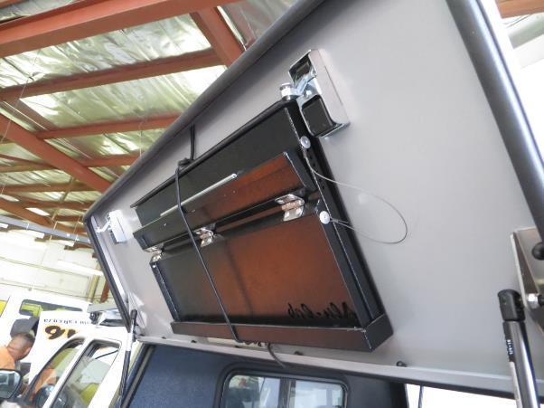
6 2.2. Sliding prep table into sliding extrusion Once the sliding extrusion is fixed, the prep table slides into it as shown in Figure 8 and Figure 9. Sliding Extrusions Figure 8: Sliding into Rope Mould Sliding Extrusions Top Section Bottom Section Figure 9: in setup position 6

 Step 2 - Fold the wire and insert into")

7 2.3. Installing prep table wire supports a) Step 1 Slide wire into 1 side of the crimper Crimper Wire Figure 10: Inserting wire into 1 side of crimper b) Step 2 - Fold the wire and insert into the other side of the crimper Crimper Wire Fold Figure 11: Inserting the wire into other side of crimper 7


8 c) Step 3 - Scrimp wires together using a crimping tool Before crimping the wires together, fit the wire fold over the 4.8x15 flange rivet and adjust the crimper to have a close fit on the rivet. Top Wire Support 4.8x15 Flange Rivet Top Section Figure 12: Adjusting Crimper for a close fit Crimping Tool Wire Fold Figure 13: Crimping wires together 8

 Step 5 Adjusting and crimping wire supports to prep table bottom section Adjust the length of the")
9 d) Step 4 Rivet wire supports to the prep table top section Insert 4.8x15 flange rivet into wire fold, then insert into pre-drilled holes located in the top section of the prep table as shown in Figure 11 above and rivet the wire support to the prep table. 4.8x15 Flange Rivet Top Wire Support Top Section Figure 14: Rivet Top Wire Support e) Step 5 Adjusting and crimping wire supports to prep table bottom section Adjust the length of the wire support before crimping it to keep the prep table bottom section 90 degrees to the top section when table unfolds. Insert 4.8x15 flange rivet into mounting hole. Bottom Section Bottom Wire Support Top Section Bottom Section Mounting holes Wire Support Figure 15: Adjusted Wire Support 9

 Step 7 Rivet wire support to bottom section Bottom")
10 f) Step 6 - Use wire crimping method in step 3 for the other end of the wire support. Wire Support Crimping Tool Figure 16: Crimping other end of wire support g) Step 7 Rivet wire support to bottom section Bottom Section Rivet Gun Figure 17: Rivet bottom wire support 10
 Step 1 Measure mounting holes")

11 Figure 18: setup complete 3. Installing prep table frame for table storage a) Step 1 Measure mounting holes into frame Measure hole positions on the frame as shown in Figure 18. This must be done for each corner of the frame. 20mm Frame Width Mounting Hole 40mm Frame Length Figure 19: Measuring mounting holes on the frame 11
 Step 3 Mark off holes on the vehicle mounting surface")

12 b) Step 2 Drill the mounting holes through the frame Drill Frame Figure 20: Drilling mounting holes on the frame c) Step 3 Mark off holes on the vehicle mounting surface Place the frame in the mounting position and mark off corresponding holes onto the vehicle surface Vehicle Mounting Surface Mounting holes Frame Figure 21: Marking off mounting holes 12


13 d) Step 4 Drilling mounting holes into vehicle surface Drill the mark off points using a drill and 4.8mm drill bit. Inside Surface of side door Hand Drill and 4.8mm Drill bit Figure 22: Drill mounting holes into canopy side door e) Step 4 Rivet the frame onto the canopy side door Place the frame in position on the inside of the side door and align the holes. Insert rivets from the outside surface of the side door into the frame mounting holes and rivet it down. Rivet Gun Outside Surface of side door Figure 23: Rivet frame from the outside surface 13


14 Frame Inside Surface of Side Door Rope for holding table 4.8x10AS Rivets Figure 24: Frame installed 4. Locking into Frame a) Step 1 Fold table close and Insert into the frame Prep table frame Figure 25: Inserting Table into frame 14


15 b) Step 2 Lock table into frame Use the rope at the bottom of the frame to fix the table in place. Swing the rope over the table and hook it onto the top of the frame. Prep table frame Locking Rope Figure 26: Fixing table in place Figure 27: Storage complete 15
M10 x 75mm Sockethead Cap Screws. 5mm Fender Washer (12) Included - (8) Required. #10 x 2.5" PH Wood Screws. (30) Included - (24) Required
 Included - (8) Required. #10 x 2.5 PH Wood Screws. (30) Included - (24) Required") Door System Unit - Hardware Tools Included: (2) 2mm Allen Wrenches, (2) 3mm Allen Wrenches, (2) 4mm Allen Wrenches, (2) 6mm Allen Wrenches, and (1) 8mm T-Handle Allen Wrench Tools Required: Phillips Screwdriver,
Door System Unit - Hardware Tools Included: (2) 2mm Allen Wrenches, (2) 3mm Allen Wrenches, (2) 4mm Allen Wrenches, (2) 6mm Allen Wrenches, and (1) 8mm T-Handle Allen Wrench Tools Required: Phillips Screwdriver,
Installation Manual for Metal Emperor Lockers
 P a g e 1 Table of Contents Page General Notes and Tools Required 2-3 Assemble Shelves with Coat Hooks/Coat Rods 4 Fastening Chart 5 Knock Down Locker Assembly (Banks of Three) 6-12 Appendix A: Dress End
Mazda BT-50 With Factory Sports Bars 2012 Current Part number: Package includes
 Tonneau Cover Fitting Instructions Mazda BT-50 With Factory Sports Bars 2012 Current Part number: 10019 Package includes 1 x Tonneau Cover 1 x Rope Track (1420mm Long) 2 x Bar Bracket (300474) 22 x 4 mm
MISCELLANEOUS CABINET REPAIRS
 MISCELLANEOUS CABINET REPAIRS 167 168 NOTES MISCELLANEOUS CABINET REPAIRS Cabinet Panel Repairs 175 SIDE PANEL REPLACEMENT - GDM SERIES INSTALLATION INSTRUCTIONS Tools Required 1/8" drill Rivet Tool Silicone
Tonneau Cover Fitting Instructions
 Tonneau Cover Fitting Instructions Package includes Nissan Navara Dual Cab NP300 / D23 With Factory Sports Bars April 2015 Current Part number: 10691 1 x Tonneau Cover 1 x Rope Track (1485mm Long) 2 x
Tonneau Cover Fitting Instructions Holden Colorado with Factory Sports Bars July 2012 Currrent Part Number: STO10054 Package includes
 Tonneau Cover Fitting Instructions Holden Colorado with Factory Sports Bars July 2012 Currrent Part Number: STO10054 Package includes D 1 x Tonneau Cover D 1 x Rope Track (1460mm) D 2 x Bar Bracket (300474)
#916 CLASSIC 16 GUN CABINET ASSEMBLY INSTRUCTIONS
 Thank you for purchasing this quality product. A list of PARTS and INSTRUCTIONS is included to assist you. Unpack and identify all parts included on the Parts List and Hardware List. If parts are missing,
INSTALLATION GUIDE Locker With Top Shelf Transit Low Roof & Nissan NV Low Roof ( Aluminum )
") INSTALLATION GUIDE 7115 Locker With Top Shelf Transit Low Roof & Nissan NV Low Roof ( Aluminum ) QUICK START GUIDE Phase 1 - Assembly q 1.1 Setup... q 1.2 Locker w/ Top Shelf Assembly... 3-5 6-13 Phase
INSTALLATION GUIDE 7115 Locker With Top Shelf Transit Low Roof & Nissan NV Low Roof ( Aluminum ) QUICK START GUIDE Phase 1 - Assembly q 1.1 Setup... q 1.2 Locker w/ Top Shelf Assembly... 3-5 6-13 Phase
Kai Installation Instructions
 Kai Installation Instructions Before Beginning Installation Read through the entire instruction thoroughly A minimum of 2 people are required for this assembly These instructions reflect typical assemblies;
FACTORY STRETCH INSTALLATION INSTRUCTIONS
 !! Important!! Make sure all power is disconnected prior to installation. Wiring to be done according to Local and National Electric Codes by a qualified electrician. Make sure the building and/or structure
Therma-Tru Door Gallery Setup Instructions Swing Unit with Hardware Kit - Hardware Part # MADGSWU15 (Swing Unit) Part # MADGHKSU10 (Hardware Kit)
 Part # MADGHKSU10 (Hardware Kit)") Swing Unit with Hardware Kit - Hardware Tools Included: 4mm Allen Wrench, 6mm Allen Wrench, 8mm T-Handle Allen Wrench (1) 3/4" Drill Bit, (1) 7/32" Drill Bit and Hole Template Guide Tools Required: Phillips
Swing Unit with Hardware Kit - Hardware Tools Included: 4mm Allen Wrench, 6mm Allen Wrench, 8mm T-Handle Allen Wrench (1) 3/4" Drill Bit, (1) 7/32" Drill Bit and Hole Template Guide Tools Required: Phillips
RAMPAGE P R O D U C T S. INSTALLATION INSTRUCTIONS BRONCO ZIPPER FASTRACK TOP PART #984xx BRONCO TOOLS REQUIRED
 RAMPAGE P R O D U C T S 84 (+/- 1/4 ) INSTALLATION INSTRUCTIONS BRONCO ZIPPER FASTRACK TOP PART #984xx BRONCO 1966-1977 TOOLS REQUIRED 3/8 WRENCH 7/16 WRENCH ½ WRENCH #2 PHILLIPS SCREWDRIVER 1/8 DRILL
Double Screen Door Installation Instructions
 Double Screen Door Installation Instructions (36) #8x1 tek screws (20) #8x1/2 tek screws Package Includes: (2) PCA Screen Doors (1) Astragal (1) Left Hand Z-bar (1) Right Hand Z-bar (1) Header Z-bar (2)
General Prisoner Transport Install Instructions PT-2-INST
 General Prisoner Transport Install Instructions PT-2-INST 50 or 60 high x 80, 100 & 120 inch long / Double Compartment Inserts Also refer to PT-A-3XX instructions for vehicle specific mounting measurements
Series 1100 Aluminum Door Canopy
 Series 00 Aluminum Door Canopy with Support Arms It is our recommendation that you read instructions carefully prior to assembly and installation. Series 00 with Support Arms MOUNTING BAR (A) TOP TRIM
TIRE RACK INSTALLATION INSTRUCTIONS Dodge Sprinter
 Aluminess Products Inc 9402 Wheatlands Ct. #A Santee, CA 92071 619-449-9930 TIRE RACK INSTALLATION INSTRUCTIONS 07-11 Dodge Sprinter Please read before beginning Stainless steel hardware may bind together
TONNEAU INSTALLATION INSTRUCTION
 TONNEAU INSTALLATION INSTRUCTION Mitsubishi MQ Triton Dual Cab With Headboard, No Sports Bars Clip On Cover July 2015 Current Package includes Part number: STO10642 1 X Tonneau cover 2 x Bar Brackets (300474)
Congratulations on your purchase of our new reproduced 1969 Mercury Cougar Stainless Steel Rocker Moldings
 Congratulations on your purchase of our new reproduced 1969 Mercury Cougar Stainless Steel Rocker Moldings Before starting installation, we recommend that you read these instructions a couple of times
TONNEAU FITTING INSTRUCTION STO 10726
 TONNEAU FITTING INSTRUCTION STO 10726 Aluminium Tray 2400 x 1900 Bunji Package includes 1 X Tonneau cover 4 x Bar Brackets (300474) 2 x Tonneau Support Bar (300517) 43 x Rivets (300482) 2 x Aluminium Rope
K9 KIT INSTALLATION INSTRUCTIONS CROWN VIC KK-K9-F7-K
 K9 KIT INSTALLATION INSTRUCTIONS 1998-2011 CROWN VIC KK-K9-F7-K TOOLS REQUIRED: Power Drill (Cordless preferable) Drill Bit Set Standard Wrench and Socket Set Metric Socket Set Screwdriver Set Torx Bit
RTS518 - Rhino Heavy Duty 2 & 3 Crossbar System Hyundai iload, imax, i800, H-1.
 RTS518 - Rhino Heavy Duty 2 & 3 Crossbar System Hyundai iload, imax, i800, H-1. NOTE: Please read these instructions carefully prior to installation. Check the contents of kit before commencing fitment
Installation Guide 40670
 Installation Guide 40670 Kargo Master Rancho Cordova, CA 95742 800-343-7486 CustomerService@KargoMaster.com DATE: Installation Instructions 40670 *PLEASE READ ALL INSTRUCTIONS AND WARNINGS PRIOR TO ASSEMBLING,
Series 1500 Aluminum Door Canopy
 Series 500 Aluminum Door Canopy with Sidewings It is our recommendation that you read instructions carefully prior to assembly and installation. Series 500 with Sidewings mounting bar (A) top trim (B)
Rhino Tracks RTS502 - Land Rover - Discovery 3, Discovery 4. - LR3, LR4.
 - Land Rover - Discovery 3, Discovery 4. - LR3, LR4. Important: Please read these instructions carefully prior to installation. Please refer to your fitting instruction to ensure that the roof racks are
TOYOTA MOTOR EUROPE CA Products Division Tel : Fax :
 TOYOTA MOTOR EUROPE CA Products Division Tel : + 32 2 745 26 77 Fax : + 33 2 745 26 99 Ordering part numbers Comments Part Numbers Wooden floor one hatch PZ449-D3C42-11 one hatch with carpet PZ449-D3C42-01
INSTALLATION GUIDE. C20-DH STRAIGHT PARTITION Sprinter Partition ( Perforated Window, No Access, Steel )
") INSTALLATION GUIDE C20-DH STRAIGHT PARTITION Sprinter Partition ( Perforated Window, No Access, Steel ) QUICK START GUIDE Phase 1 - Assembly q 1.1 Setup... q 1.2 Partition assembly... 3-4 5-6 Phase 2 -
INSTALLATION GUIDE C20-DH STRAIGHT PARTITION Sprinter Partition ( Perforated Window, No Access, Steel ) QUICK START GUIDE Phase 1 - Assembly q 1.1 Setup... q 1.2 Partition assembly... 3-4 5-6 Phase 2 -
How to Install Custom Real Wood and Faux Wood Blinds
 Before you begin your installation: READ ALL INSTALLATION INSTRUCTIONS! Make sure that you have all tools and hardware needed for installation. Check the installation surface (wall, ceiling, or window
Shoreline Canopy and Canopy Frame Installation Instructions
 Shoreline Canopy and Canopy Frame Installation Instructions INTRODUCTION The Shoreline canopy is used with the Shoreline Cantilever boat lifts. There are several different sizes and a variety of color
FITTING INSTRUCTIONS FOR CAMEC 4RC ODYSSEY PREMIUM PUSH OUT WINDOW
 PAGE 1 OF 5 FITTING INSTRUCTIONS FOR CAMEC 4RC PUSH OUT WINDOW Ver.1 - April 2013 Rev 1 INSTALLATION INSTRUCTIONS PAGE 2 OF 5 1. To install Odyssey Premium Window correctly please follow these Fitting
K2 Assembly Instructions - Page 1.
 K Assembly Instructions - Page. Recommended Tools: Electric/Cordless Drill # Phillips Bit with Extension #0 Drill Bit /4 Drill Bit Pop Rivet Gun / Wrench / Socket Wrench Locking Pliers Rubber Mallet Measuring
K9 KIT INSTALLATION INSTRUCTIONS CROWN VIC with Fire Suppression System Model KK-K9-F7-K-FS
 K9 KIT INSTALLATION INSTRUCTIONS 2005-2011 CROWN VIC with Fire Suppression System Model KK-K9-F7-K-FS TOOLS REQUIRED: Power Drill (Cordless preferable) Drill Bit Set Standard Wrench and Socket Set Metric
Level, Pliers, 3/8" Electric Drill, Carpenters Square, Tape Measure, Metal Hack Saw, Silicone Caulking, Screw Drivers (Regular & Phillips)
") Delta Door Canopy Installation Instructions Recommended Tools: Before You Begin: Level, Pliers, 3/8" Electric Drill, Carpenters Square, Tape Measure, Metal Hack Saw, Silicone Caulking, Screw Drivers (Regular
Delta Door Canopy Installation Instructions Recommended Tools: Before You Begin: Level, Pliers, 3/8" Electric Drill, Carpenters Square, Tape Measure, Metal Hack Saw, Silicone Caulking, Screw Drivers (Regular
FOLDING HARDWARE STARTEC T-SNAP G2/G4
 FOLDING HARDWARE STARTEC T-SNAP G2/G4 T-SNAP G2 T-SNAP G4 Technical data: 40 kg for package throughout Height according 36+7 mm Fix bracket every 400 mm T-SNAP G2: 1x door leaf package T-SNAP G4: 2x door
Audi Q7 Running board Fitting Instructions
 Audi Q7 Running board Fitting Instructions Parts list Item Designation 1 2 3 4 5 6 7 Running board Support bracket Covers Screw M8x40 Screw M8x20 Blind rivet Screw for plating 4.8x16 Quantity 2 6 4 14
Calf-Tel Pen System Assembly Instructions
 Calf-Tel Pen System Assembly Instructions (Instructions work for 4, 6, and the 7 Pen Systems) 1 ASSEMBLY OF PEN FRONT AND WALLS START THE ASSEMBLY BY LINING UP THE TWO UNI-DIRECTIONAL ARROWS IN THE TOP,
HARDWARE KIT # KKM or Rear Compartment: (Some hardware not used in all applications)
") PRISONER TRANSPORT INSTRUCTIONS for CHEVROLET EXPRESS VAN PT-C01-100-2A TOOLS REQUIRED: Standard and Metric Socket Sets Awe or Scribe Tape Measure Impact Gun (recommended) Pry-bar Caulk gun Drill & drill
PRISONER TRANSPORT INSTRUCTIONS for CHEVROLET EXPRESS VAN PT-C01-100-2A TOOLS REQUIRED: Standard and Metric Socket Sets Awe or Scribe Tape Measure Impact Gun (recommended) Pry-bar Caulk gun Drill & drill
INSTALLATION INSTRUCTIONS DODGE RAM 2 & 4WD 1500 PART # P5058
 INSTALLATION INSTRUCTIONS 2009-13 DODGE RAM 2 & 4WD 1500 PART # P5058 PARTS LIST: Qty Description Qty Description 1 Grille Guard 12 12-1.75mm Hex Nuts 2 Upper Frame Mounting s (for trucks without tow hooks
NORMAN SHUTTERS INSTALLATION INSTRUCTIONS. 4 Sided Z Frame. (Inside Mount - 2 panel) Getting Started
 Getting Started") NORMAN SHUTTERS INSTALLATION INSTRUCTIONS 4 Sided Z Frame (Inside Mount - 2 panel) Getting Started Recommended Tools: Nail Gun or Drill, Tape Measure, Torpedo Level, Box Knife, 6 Philips head driver Make
NORMAN SHUTTERS INSTALLATION INSTRUCTIONS 4 Sided Z Frame (Inside Mount - 2 panel) Getting Started Recommended Tools: Nail Gun or Drill, Tape Measure, Torpedo Level, Box Knife, 6 Philips head driver Make
FORD TRANSIT CONNECT LWB WALL LINER INSTALLATION INSTRUCTIONS
 FORD TRNSIT ONNET LWB WLL LINER INSTLLTION INSTRUTIONS NOTES: 1. Before commencing, remove all wall liners and D Rings already installed in the vehicle. 2. onsult layout PDF and compare vehicle layout
Ford Pick Up Rear leaf Spring Kit Installation Instructions
 1948-1956 Ford Pick Up Rear leaf Spring Kit Installation Instructions 1-800-984-6259 www.totalcostinvolved.com Parts 48 inch leaf (2) springs (4) U-bolts 3/8-24 x l 1/4bolts (16) & nuts (2) 1/2-20 x 4
DuraRac Shelving System
 GM Full Size Van Assembly Installation Instructions Sheet 1 of 13 BEFORE YOU START! IMPORTANT INSTALLATION STEPS ARE DENOTED USING A STOP SIGN. THESE STEPS MUST BE PERFORMED IN THE SPECIFIED ORDER TO ENSURE
revised. You can make sure you are looking at the most recent KEEPING SERVICE INFORMATION CURRENT
 1 to the Kwikee Products Service Training. It is our sincere hope that the information you gain from this training will enhance your confidence in and familiarity with the products we manufacture. The
Installation Instructions PREMIUM Replacement Top (Part # )
") 0 7-0 9 U n l i m i t e d ( 4 D o o r ) NOTE: Read entire instructions thoroughly before installing this product. It is recommended to install this Top when temperatures are above 70 degrees. The top can
0 7-0 9 U n l i m i t e d ( 4 D o o r ) NOTE: Read entire instructions thoroughly before installing this product. It is recommended to install this Top when temperatures are above 70 degrees. The top can
Care Instruction: Wash vehicle roof prior to installing Rhino Tracks.
 Important: Please read these instructions carefully prior to installation. Please refer to your fitting instruction to ensure that the roof racks are installed in the correct locations. Check the contents
SOFT TONNEAU FITTING INSTRUCTION. Toyota Hilux Dual Cab SR J Deck Without Sports Bar. October 2015 to Current. Part number: STO 10786
 SOFT TONNEAU FITTING INSTRUCTION Toyota Hilux Dual Cab SR J Deck Without Sports Bar October 2015 to Current Part number: STO 10786 Package includes 1 X Tonneau cover 2 x Bar Brackets (300474) 1 x Tonneau
Master Your Terrain (307) Extreme Duty ROCK RAILZ Jeep Cherokee. Installation Instructions
 Extreme Duty ROCK RAILZ Jeep Cherokee. Installation Instructions") Master Your Terrain (307) 775 9565 www.tntcustoms.com Extreme Duty ROCK RAILZ Jeep Cherokee Installation Instructions Congratulations for purchasing a TNT. Extreme Duty Rock RailZ for your Jeep Cherokee.
Master Your Terrain (307) 775 9565 www.tntcustoms.com Extreme Duty ROCK RAILZ Jeep Cherokee Installation Instructions Congratulations for purchasing a TNT. Extreme Duty Rock RailZ for your Jeep Cherokee.
4. Partially open the operating panel and tilt the top toward the interior of the door (Figure 4). Lift the panel off the sill and set it aside.
. Lift the panel off the sill and set it aside.") Effective Date: 10/1/2017 Tools Needed Kit Contents Hardware Kit Safety Glasses Cordless drill Phillips screw bit Two-step drill bit (3/8-1/8 ) utility knife Interior Mullion Exterior Mullion Cover clamps
Effective Date: 10/1/2017 Tools Needed Kit Contents Hardware Kit Safety Glasses Cordless drill Phillips screw bit Two-step drill bit (3/8-1/8 ) utility knife Interior Mullion Exterior Mullion Cover clamps
LOCKN LOAD FIRST TIME INSTALLATION
 LOCKN LOAD TM TRACK MOUNTING KIT NISSAN NAVARA D40 2004-2015 2 BAR TRACK HEAVY DUTY ROOF RACK SYSTEM MAX VEHICLE ROOF LOAD RATING: 100KG TOTAL LOAD EQUALS WEIGHT OF ROOF RACKS + ACCESSORIES + CARGO FIRST
INSTALLATION INSTRUCTIONS
 INSTRUCTIONS Accessory P/N 08U35-SZN-200 Application 2012 ZDX Publications No. BII 46578 Issue Date AUG 2011 PARTS LIST 2 Rivet nuts (5 mm) Cargo cover 8 Self-tapping screws, 5 x 50 mm Left base 8 Self-tapping
Wildeck Overhead Safety Gate. General
 Wildeck Overhead Safety Gate General Safe and efficient movement of palleted material to and from your mezzanine is a requirement, and the Wildeck Overhead Safety Gate delivers every time. Workers on the
METAL BLINDS. Deluxe GETTING STARTED OPTIONAL HARDWARE. A few simple tools are required: STANDARD HARDWARE
 METAL BLINDS Deluxe GETTING STARTED OPTIONAL HARDWARE A few simple tools are required: Steel Tape Measure Pencil Level Hold Down Brackets with Screws Extension Bracket Power Drill and Drill Bits Flathead
RETRACTABLE SCREEN ASSEMBLY AND INSTALLATION INSTRUCTIONS. DOUBLE INSWING (Retro) / (Full-Size) FIG. 1A STEP 1: REVIEW & CHECK FIG.
 / (Full-Size) FIG. 1A STEP 1: REVIEW & CHECK FIG.") STEP 1: REVIEW & CHECK ) CONFIRM DOOR HEIGHT & WIDTH You have purchased a DOUBLE Retractable Screen for an INSWING door. HEIGHT: This unit is available in two sizes: Retro and Full-Size. Please make sure
STEP 1: REVIEW & CHECK ) CONFIRM DOOR HEIGHT & WIDTH You have purchased a DOUBLE Retractable Screen for an INSWING door. HEIGHT: This unit is available in two sizes: Retro and Full-Size. Please make sure
RLZ-02 - Rear Cross Bar, Ford Transit Connect.
 Important: Please read these instructions carefully prior to installation. Please refer to your fitting instruction to ensure that the roof racks are installed in the correct locations. Check the contents
43107 Rhino Jerry Can Holder Rhino Jerry Can Holder - Horizontal
 Important: Please read these instructions carefully prior to installation. Check the contents of kit before commencing fitment and report any discrepancies. Clean the alloy tray prior to installation.
Installation and Operating Instructions
 INSTRUCTIONS Installation and Operating Instructions In these installation instructions is described the replacement of the elevating support with gas springs. This conversion kit applies to all California
Mounting a BalanceBox 400 to a brick wall
 Unpack the BalanceBox 400 and remove the Wall frame cover and its bag of screws. Slide the cover out at the top. NOTE: the cover is NOT included with the BalanceBox 400H LOCK SCREW HOLE MOBILE STAND MOUNTING
INSTALLATION GUIDE FTX FLOOR Ford Transit ( 148" Extended Wheelbase )
") INSTALLATION GUIDE 6540-FTX FLOOR Ford Transit ( 148" Extended Wheelbase ) QUICK START GUIDE Phase 1 - Assembly q 1.1 Setup... 3-4 Phase 2 - Installation q 2.1 Install Preparation... q 2.2 Floor Installation...
INSTALLATION GUIDE 6540-FTX FLOOR Ford Transit ( 148" Extended Wheelbase ) QUICK START GUIDE Phase 1 - Assembly q 1.1 Setup... 3-4 Phase 2 - Installation q 2.1 Install Preparation... q 2.2 Floor Installation...
INSTALL LOAD BED TRACKS
 Universal LOAD BED TRAY & Load BArs TRBU001 / KRLBUNI1 INSTALL TIME: 2.5 Hours READ ME FIRST: Thank you for purchasing a Front Runner Slimline II Load Bed Rack or Load Bar Kit. Your Kit will contain the
IMPORTANT INSTALLATION GUIDE VALENCIA ANGLE CORNER SHOWER READ ALL INSTRUCTIONS CAREFULLY BEFORE STARTING THE INSTALLATION
 INSTALLATION GUIDE VALENCIA ANGLE CORNER SHOWER SEALANT REQUIRED TO COMPLETE THIS INSTALLATION: (Supplied) Sika Sikasil NG (Arctic White) To seal the WHITE shower door and returns to the shower tray. Usage:
CROWN IMPERIAL ASSEMBLY INSTRUCTIONS
 CROWN IMPERIAL ASSEMBLY INSTRUCTIONS Standard Drawer Box Page 1 of 14 Standard Drawer Box Parts Parts Supplied B C D A E F G Page 2 of 14 Part Letter Part Name Quantity 300-600 Deep Pan A Base Panel 1
RH-412 STEEL DOORS INSTALLATION INSTRUCTIONS
 RH-412 STEEL DOORS INSTALLATION INSTRUCTIONS By following the steps outlined below, the assembly, installation and adjustment of the steel doors, will be a simple process. Let s start with the Driver Side.
FRP and CF Airbox / Plenum Assembly Instructions BMW M20 6cyl ITB Kit
 FRP and CF Airbox / Plenum Assembly Instructions BMW M20 6cyl ITB Kit sales@racehead.com.au Xinyi Dist, Taipei, Taiwan +886 975 292 194 Grays Pt, NSW, Australia +61 408 608 318 First Up Thanks for supporting
INSTALLATION GUIDE. C20-FTL STRAIGHT PARTITION Transit Partition ( Perforated Window, No Access, Steel )
") INSTALLATION GUIDE C20-FTL STRAIGHT PARTITION Transit Partition ( Perforated Window, No Access, Steel ) QUICK START GUIDE Phase 1 - Assembly q 1.1 Setup... q 1.2 Partition Assembly... 3-5 5-6 Phase 2 -
INSTALLATION GUIDE C20-FTL STRAIGHT PARTITION Transit Partition ( Perforated Window, No Access, Steel ) QUICK START GUIDE Phase 1 - Assembly q 1.1 Setup... q 1.2 Partition Assembly... 3-5 5-6 Phase 2 -
French Door W/Cut-Out (Outside Mount L-Frame-Single Panel)
") NORMAN SHUTTERS INSTALLATION INSTRUCTIONS French Door W/Cut-Out (Outside Mount L-Frame-Single Panel) Getting Started Recommended Tools: Nail Gun or Cordless Drill, Tape Measure, Torpedo Level, Box Knife,
NORMAN SHUTTERS INSTALLATION INSTRUCTIONS French Door W/Cut-Out (Outside Mount L-Frame-Single Panel) Getting Started Recommended Tools: Nail Gun or Cordless Drill, Tape Measure, Torpedo Level, Box Knife,
Care Instruction: Wash vehicle roof prior to installing Rhino Tracks.
 Important: Please read these instructions carefully prior to installation. Please refer to your fitting instruction to ensure that the roof racks are installed in the correct locations. Check the contents
INSTALLATION INSTRUCTIONS RH 412 STEEL DOORS
 By following the steps outlined below, the assembly, installation and adjustment of the steel doors, will be a simple process. Let s start with the Driver Side. Note: Having the hood open makes the job
INSTALLATION INSTRUCTIONS
 INSTALLATION INSTRUCTIONS Single Car Clopay WindCode Instructions (For use with Insulated and Uninsulated Steel Residential Garage Door Instruction Manual) Things to Know Before You Begin This is a supplement
INSTALLATION GUIDE. C30-NL STRAIGHT PARTITION Nissan NV ( Swing Door, Steel )
") INSTALLATION GUIDE C30-NL STRAIGHT PARTITION Nissan NV ( Swing Door, Steel ) QUICK START GUIDE Phase 1 - Assembly q 1.1 Setup... q 1.2 Partition assembly... 3 to 4 5 Phase 2 - Installation q 2.1 Tips on
INSTALLATION GUIDE C30-NL STRAIGHT PARTITION Nissan NV ( Swing Door, Steel ) QUICK START GUIDE Phase 1 - Assembly q 1.1 Setup... q 1.2 Partition assembly... 3 to 4 5 Phase 2 - Installation q 2.1 Tips on
Cleaning. This instruction will cover installation of the following units Codes:
 Cleaning *** All chrome surfaces should be cleaned using a clean damp cloth. *** No abrasive cleaning agents or materials should be used. *** General glass cleaner can be used for the screen, but ensure
Gen 2.0 Side Patio Rail Kit OEM INSTALLATION MANUAL
 Gen 2.0 Side Patio Rail Kit OEM INSTLLTION MNUL TLE OF CONTENTS Safety Information 2 Preparation 2 Resources Required 2 Patio Railing Installation 3 Hinge racket 3 Keeper ases 4 Patio Railing Operation
INSTALLATION INSTRUCTIONS KK-K9-F14-K K9 KIT FOR FORD EXPEDITION
 INSTALLATION INSTRUCTIONS KK-K9-F14-K-32 32 K9 KIT FOR 2003-2016 FORD EXPEDITION TOOLS REQUIRED: Power Drill Drill Bit Set Standard & Metric Socket Sets Phillips Screw Driver Open End Wrench Set Wire Cutters
Getting Started. Recommended Tools: Nail Gun or Drill, Tape Measure, Torpedo Level, Box knife, Countersink Drill Bit, #2 Phillips Head Drill Tip.
 NORMAN SHUTTERS INSTALLATION INSTRUCTIONS BI-FOLD TRACK Getting Started Recommended Tools: Nail Gun or Drill, Tape Measure, Torpedo Level, Box knife, Countersink Drill Bit, #2 Phillips Head Drill Tip.
OZARK DOOR CANOPY ASSEMBLY INSTRUCTIONS
 OZARK DOOR CANOPY ASSEMBLY INSTRUCTIONS Recommended Tools: Level, Pliers, 3/8" Electric Drill, Carpenters Square, Tape Measure, Metal Hack Saw, Silicone Caulking, Screw Drivers (Regular & Phillips) Before
How To Measure Your Finished Opening
 3000 Series Bifold Doors How To Measure Your Finished Opening MEASURE FROM RIGHT TO LEFT 2 PLACES (WIDTH) MEASURE FROM TOP TO BOTTOM 2 PLACES (HEIGHT) Tools Required for Assembly: Tools Needed: Phillips
RTS506 NISSAN Pathfinder Two Cross Bar Track Mount System
 Important: Please read these instructions carefully prior to installation. Please refer to your fi tting instruction to ensure that the roof racks are installed in the correct locations. Check the contents
ZODIAC 601 XL UPRIGHT CHANNELS 6B5-6. Top and bottom outboard flange is joggle to overlap the.093 extrusion 6B2-3 and 6B11-1
 UPRIGHT CHANNELS 6B5-6 Top and bottom outboard flange is joggle to overlap the.093 extrusion 6B2-3 and 6B11-1 Length: fits between the bottom and top longerons. Clamp the upright channel to the rear frame
INSTRUCTIONS High Tech II Unit Assembly
 INSTRUCTIONS High Tech II Unit Assembly The following instruction is a guideline, illustrating suggested methods, assembly sequence, and tool selection. Actual assembly may vary by each situation. Careful
NEW CONSTRUCTION PATIO DOOR INSTALLATION INSTRUCTIONS (WITH NAILING FLANGE)
") NEW CONSTRUCTION PATIO DOOR INSTALLATION INSTRUCTIONS (WITH NAILING FLANGE) Slim Line & Classic French Style Patio Doors Materials included: (2) #10 x 2-1/2" Phillips Pan head keeper s (2) 3/8" Hole plugs
NEW CONSTRUCTION PATIO DOOR INSTALLATION INSTRUCTIONS (WITH NAILING FLANGE) Slim Line & Classic French Style Patio Doors Materials included: (2) #10 x 2-1/2" Phillips Pan head keeper s (2) 3/8" Hole plugs
INOVO 2-LITE SLIDING PATIO DOOR
 INOVO 2-LITE SLIDING PATIO DOOR ASSEMBLY AND INSTALLATION INSTRUCTIONS IMPORTANT: READ THE INSTRUCTIONS AND FAMILIARIZE YOURSELF WITH THE DOOR PARTS AND PIECES BEFORE BEGINNING ASSEMBLY AND INSTALLATION.
User Instructions Multiline Otter Scoreboard Caddy Assembly
 List of parts: User Instructions Multiline Otter Scoreboard Caddy Assembly Single Caddy Double Caddy 1 1 Base assembly with attached wheels 2 4 1 1 2 4 4 8 10 20 12 Uprights (60 or 74 aluminum extrusion)
Bi-Pass And Bi-Fold Sliders
 Bi-Passs and Bi-Fold Sliders Installation Guide Bi-Pass And Bi-Fold Sliders Tools required: Hand Drill Counter Sink Drill BitSet #8 Philips Screw Driver Measuring Tape Level What s Included: Panels with
A-LOOK ver 1 A-LOOK TM. Installation Manual
 A-LOOK ver 1 A-LOOK TM Installation Manual Tools Required Pencil Measuring Tape Drill Hack Saw with 12D/32T Blade Jigsaw Self-Centering Punch Framing Square 7/16" Wrench Ladder 2" or 3" Paint Brush for
80011, SIDED HUNTING BLIND Component Chart
 80011, 80021 4 SIDED HUNTING BLIND Component Chart 80011: 15007 Guidesman decal 80021: 15009 Terrain decal Inside Blind: 1606 Serial Tag, (2) 0080 Rivet 81010 Roof 80011-KIT Hardware Kit (3) Sidewall Window
77.5 degrees REAR CHANNEL PLYWOOD TEMPLATE
 77.5 degrees REAR CHANNEL PLYWOOD TEMPLATE Ref. 6-B-14 Make following template: Vertical distance = 300mm Layout dimensions shown in the bottom right table on drawing 6-B-14 Top and bottom are square to
INSTALL/REMOVAL INSTRUCTIONS: WINDOW REGULATOR
 REMOVAL/INSTALL OF WINDOW REGULATOR (740-666) Lincoln Town Car 1990 94 General Tech Tips: Use painter s tape rather than duct tape to secure window. It will not damage paint or leave sticky residue. A
BioPrism Solid Surface
 Please read all instructions before installing products. These instructions are intended for use with InPro s standard toilet partitions, which include 58 high doors and wall panels, when deviating from
Instructions for the installation of Ellison Bronze balanced door models #137 & 138
 1. A packing list will be found in crate No. 1 of each shipment. The parts in the crates should be checked with this list. If there is any discrepancy, notify Ellison Bronze at once. 2. All parts are numbered.
INSTALLATION GUIDE 2009-CURRENT HUMMER H3T PRODUCT CODE:
 INSTALLATION GUIDE 2009-CURRENT HUMMER H3T PRODUCT CODE: 268 June 22, 2010 TOOLS NEEDED COMPONENTS INCLUDED P2 Tip 3/8" Drill Rubber Gasket(s) x 2 Bracket(s) x 2 1/2" Drill Bit Bulkhead Flange #2 Phillips
DURASTALL SHOWER STALL ASSEMBLY INSTALLATION REPAIR PARTS FOR ONE OF THE FOLLOWING MODELS:
 DURASTALL SHOWER STALL ASSEMBLY INSTALLATION REPAIR PARTS FOR ONE OF THE FOLLOWING : MODEL: 80 (32 ) 140 (36 ) Cabinet (rigid corners) with Standard Base complete with Curtain and Valve assembly. MODEL:
INSTALLATION STEPS MAXIMUS-3.COM
 JK WRANGLER MAXIMUS-3 JK ROOF RACK/PLATFORM MAXIMUS-3 RHINO RACK ROOF PLATFORM/RACK IS NOT COMPATIBLE WITH JK 2-DOORS. THIS PRODUCT IS NOT DESIGNED TO WORK WITH JK SOFT TOP ROOF. INSTALLATION GUIDES Please
Assembly Instructions 10 X 10 Aluminum Frame Building
 Assembly Instructions 10 X 10 Aluminum Frame Building 27 97 9 8 47 36 74 52 10 10 X 10 Square Building W/ Dome Includes: The Steel Entry Door with a Dead Bolt Lock assembly and Aluminum Door Frame. Metal
RTS509 Rhino Heavy Duty Track Mount System - MITSUBISHI TRITON ML
 RTS509 Rhino Heavy Duty Track Mount System - MITSUBISHI TRITON ML Important: Please read these instructions carefully prior to installation. Please refer to your fitting instruction to ensure that the
INSTALLATION INSTRUCTIONS
 INSTALLATION INSTRUCTIONS PARTS REQUIRED Single QuickStand Lite Parts A (1) Lower Arm A B C D B (1) Upper Arm C (1) Base D (1) Base Plate E (1) M8 Dynamic Arm Long F (1) Clamp Bracket G H (1) VESA Plate
1 Intro Folding Panel System 12 Panel Display Backwall Set-up Instructions 1. 2.
 1 Intro Folding Panel System 12 Panel Display Backwall Set-up Instructions Right Stack top panels on bottom panels Unfold display wall Set in desired configuration Wrong Pull from here Remove each folded
PROTECT-A-POOL INGROUND REMOVABLE SAFETY FENCE
 PROTECT-A-POOL INGROUND REMOVABLE SAFETY FENCE I N S T A L L A T I O N I N S T R U C T I O N S INSTALLATION TOOLS The following tools are required for installation. Chalk Pencil Utility Knife Tape Measure
Austin Standing Seam Awning Assembly and Installation Instructions. Assembly Instructions
 Austin Standing Seam Awning Assembly and Installation Instructions Be sure to use safety glasses when assembling and installing the awning. Some metal parts may have sharp edges. Use work gloves to handle
RBP-1215B-RX DODGE RAM QUAD CAB RX3
 RBP-1215B-RX3 2002-2017 DODGE RAM 15-3500 QUAD CAB RX3 Passenger side RX-3 Side Step Drill Template Passenger side rear Modular Bracket (6) L Support Brackets Driver side rear Modular Bracket Driver side
Assembly Instructions Signature Choral Riser 4-Step Model
 Assembly Instructions Signature Choral Riser 4-Step Model Contents Important User Information...........................2 General...2 Manufacturer...2 Intended Use...2 Warranty...2 Safety Precautions.................................3
LOCKN LOAD FIRST TIME INSTALLATION
 LOCKN LOAD TM TRACK MOUNTING KIT ISUZU MU-X 2013+ LS-M & LS-U MODELS ONLY 3 BAR TRACK HEAVY DUTY ROOF RACK SYSTEM MAX VEHICLE ROOF LOAD RATING: 100KG TOTAL LOAD EQUALS WEIGHT OF ROOF RACKS + ACCESSORIES
Dublin Stalls Installation Instructions
 Dublin Stalls Installation Instructions RAMM Horse Fencing and Stalls 13150 Airport Hwy. Swanton, OH 43558-9615 1-800-434-8456 Rev. 9/13/17 Part Identification Round Track Bracket (4) (Not Painted) Round