"NuHybrid" Solid-State Headphone Amplifier Assembly instructions
|
|
|
- Blake Johnston
- 6 years ago
- Views:
Transcription
1 "NuHybrid" Solid-State Headphone Amplifier Assembly instructions What you need: The bare PCB plus Korg Nutube 6P1 (from pmillett.com via ebay) The parts (from Mouser) A soldering iron and solder (Tin/Lead 63/37 is the easiest to work with - lead-free solder is more difficult) Wire cutters ("diagonal cutters") DMM (Digital Multimeter) The following are optional, but recommended: Needle-nose pliers To order the parts from Mouser, go to or go to the "Tools" page at and enter this access code in "Cart Sharing" towards the bottom of the page: b68a30231c The Mouser BOM includes all of the parts needed to build the NuHybrid except for the PCB and the Korg Nutube, which are available from You can also refer to the bill of materials at the end of this document for additional info. Occasionally one of the parts on the BOM may be out of stock. The BOM has some suggestions for alternate parts that can be used instead, as well as alternate parts that are available from Digi-Key. Note that the Mouser BOM may be updated from time to time as parts become difficult to source. When assembling, keep the BOM and schematic handy, in case you have any questions about what parts go where. It is assumed that the builder has some basic electronics knowledge, like knowing which end of the soldering iron to hold in the hand, and hopefully some experience building electronics. However, this is a very easy project and is suitable for a first-time builder. If you are new to soldering, it's highly recommended that you review one or more of the excellent on-line soldering tutorials. Just search "soldering tutorial" on the web and/or YouTube. There is nothing sacred about the order that is listed for assembly. It can be convenient to build starting with low-profile components, and work your way up to taller parts, so it's easier to solder on the board backside. That is the way the instructions read. But you can install parts in any order you want.
 next to it.")
2 PCB Assembly Step 1. Introduction Start with familiarizing yourself with the bare PC board: You'll see that each part has an outline silkscreened on the board, and a reference designator (name) next to it. Parts are numbered starting at the lower left, so you can expect to find resistor R1 somewhere near the lower left corner. Some parts, like resistors, have no polarity and can be installed in either orientation. Others, like diodes and electrolytic capacitors, need to be installed in a particular direction. These parts have the orientation clearly marked on the silkscreen with a dot for the positive terminal for capacitors, and a bar and dot for the cathode side of diodes.

3 2. Install resistors Each bag of parts from Mouser looks like this: Match the Mouser part number or the description with the parts on the BOM. In this case, you will see that 33.2k resistors are installed at R12 and R15.

 so")

4 Note that the resistors may be different colors. In no particular order, install the resistors. After you remove them from the bag, you'll need to bend the leads (you can just use your fingers) so they look like this: Next, insert them into the PCB in the appropriate spots: Push them down flush with the board:


5 And bend the leads on the backside slightly: Next, solder the leads. Touch the soldering iron tip to both the pad and the lead, and apply a little solder:
6
, trim the excess wire leads:")

7 Next, using wire cutters ("diagonal cutters"), trim the excess wire leads: It should wind up looking like this: Now, repeat this process for all of the resistors.

8 When you re done, the board should look like this:

9 2. Install diodes The diodes are installed the same way as the resistors. Diodes need to be installed in the correct orientation, so be careful and double-check to make sure they are pointed the right way before soldering. Note the diodes have a band on one end that matches with the band on the PCB silkscreen, and the PCB also has a dot near that end. Be careful, as the two 1N4148 diodes (D3 and D4) look virtually identical to the 1N5245B Zener diode (D2)! As with the resistors, bend the leads and solder, then trim the excess lead wires. Check again that they are in the right way by matching them to this photo:

10 3. Install IC sockets Two IC sockets are installed for the opamps, so you can change them to different ones if desired. Note the orientation of the sockets - there is a small notch to indicate pin 1, which is aligned with the PCB silkscreen:

11 The IC sockets are soldered in as before, but since they have short pins that cannot be bent, they somehow need to be held in place while you solder the pins. If you are dexterous you can hold them with one finger while soldering, or just use a piece of tape:

12 Flip the board over and solder the pins as before. No trimming is needed. It should look like this when you're done: By the way, don't worry about the flux that gets splattered on the board when soldering. It's harmless...

13 4. Install film capacitors Next, install the film capacitors. (Note that the parts provided might be slightly different sizes or colors than those shown). These are small parts with the two lead wires sticking out one side, so you don't have to bend the leads before inserting them into the PCB: Bend the leads over a bit to hold them in the board, solder, and trim the excess.


14 5. Install the small electrolytic capacitors Install the smaller electrolytic capacitors. Be VERY careful that they are installed the correct way - the PCB has a dot marking the positive terminal of the capacitors. The longer lead wire is the positive terminal. Note that on the capacitor body, only the negative side is labeled so the other side is positive. Insert them, bend the leads, solder and trim as before. Check again that the orientation is correct:

15 6. Install large electrolytic capacitors Install the four larger electrolytic capacitors, the same way as the smaller:

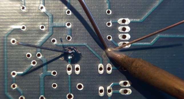
16 7. Install the bias adjust trim pots, transistors and voltage regulator Install the bias adjust pots (R17 & R18), three small transistors (Q1, Q2, and Q3) and a voltage regulator IC (U3). Note that Q1 is a 2N7000 MOSFET, and Q2 & Q3 are 2N3904 NPN transistors they look almost the same, but you can read the part number on the device. You need to slightly bend the leads of the transistors and voltage regulator then push them into the PCB. Bend the leads slightly on the back, solder, and trim the leads. (Note that Q1 isn t visible in this photo it is off to the left).

17 8. Install the test points There are three small test points installed near the opamps. Insert them and solder.

18 9. Install the relay K1 and common mode inductor L1 Just place them the relay will only go in one way, and the inductor works either direction bend the leads a bit, solder, and trim the excess leads. Note that the relay may be a different color

19 10. Install volume control RV1, headphone jack J3, and switch S1 These parts are simply inserted into the PCB and soldered. Some may snap into the PCB and stay put, and some you may need to use tape or your fingers to hold it in place while you solder them in: Make sure you have the parts seated all the way down on the PCB before fully soldering them in. It's best to solder only one lead, then inspect the part to see if it is fully seated on the PCB. If not, heat the solder joint while pushing the part into the PCB.
 when you solder it in.")

20 11. Install power jack J1, input jack J4, and line out jack J2 Install the jacks on the rear edge of the PCB. J2 and J4 snap into the PCB, but J1 may need to be held in with tape (or your fingers) when you solder it in. As before, make sure the parts are fully seated on the PCB before completely soldering them in! 12. Install the "power on" LED D5 The LED is installed like the small capacitors. Just make sure it's pointed off the edge of the PCB!
, and apply")
21 13. Install the Nutube Last part! First, peel the backing off of the two squares of double-stick foam tape (these are supplied with the PCB and Nutube), and apply them to the PCB in the area indicated on the silkscreen: The foam tape holds the Nutube in place.

22 Next, remove the backing from the top of the tape to expose the adhesive. CAREFULLY insert the Nutube into the PCB and press it onto the tape. The pins are very soft and fragile, so go slow, and be careful not to bend the pins. Solder the pins.

23 12. Inspection Before you plug the opamps into their sockets, first do a thorough visual inspection of the PCB. Make sure all the parts are soldered in, and all are oriented correctly. Match it to the photo below:


24 13. Install the opamps U1 and U2 into the sockets Now, plug the opamp ICs into their sockets. You may need to gently bend the leads together so they are parallel to fit the socket: Then press them into the sockets. Make sure you align pin 1 with the notch on the sockets, and the notch on the PCB silkscreen! Be careful that the leads don't get bent! If they do, pull the IC out of the socket and straighten the leads, and try again. They should look like this - double-check the orientation to match the photo:

25 14. Power-on test Verify that your power adapter is 24V DC (check the label). Connect it to the power jack on the board, and plug it in. Flip the power switch on (on is up). The power LED should light, and you should see a bluish-white glow from the Nutube triodes if not, unplug the power, and go back and check to make sure everything is soldered in correctly!
 to get about 11V again.")
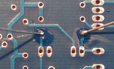
26 15. Output bias adjustment Set the DMM to measure DC volts, and position the leads of the DMM on TP1 and TP3 as shown in the photo below. Adjust R18, the L Bias potentiometer, to get a reading of about 11V. Move the positive lead to TP2, and adjust R17 ( R Bias ) to get about 11V again. If you cannot adjust the pot to get to 11V, unplug power and go back and check everything again. Note that you can experiment with this setting to change the sound of the amp. There will be no harm to the amp in setting this wherever you like.

27 23. Listen! At this point, all checks out. Plug the amp into a music source, headphones into the output, and listen. Note that the power-on mute circuit will not turn on the headphones for about 5-10 seconds after power is turned on. This avoids a big thump as the amp powers up. 24. Package the amp Since there are no hazardous voltages, it's perfectly OK to listen to the amp in a "bare board" configuration. You need to be very careful that the board doesn't sit down on anything metal, or you risk causing a short and damaging something! The BOM includes a plastic case that the PCB will fit into. The screws provided with the enclosure are used to secure the board. If you prefer, you can package the amp into some other enclosure as well. Oh, and the volume control knob provided in the BOM just pushes on to the volume control shaft. Don't put it on until you have everything done, though, as it is VERY hard to pull off once it's in place!

28 Troubleshooting If the amp doesn't work, there is a 95% chance that there is a solder problem, either an open joint or shorted leads. Go back and inspect all of the solder joints one by one. If any look suspect, re-heat them with the soldering iron. It is common for novice soldiers to get solder on the exposed lead, but not flow the solder onto the PCB pads. The joints should look like little volcanoes, with a solder "fillet" from the lead to the pad. Good Bad If there is a big blob of solder, remove the excess using solder braid, or heating it and whacking the board against a table (gently!). If the solder is good, the next most likely issue is that a component is installed incorrectly. This can mean a part is installed the wrong orientation, or a part is installed in the wrong place. Look over the board. Sometimes it helps to have somebody else inspect it - often you will overlook the same error over and over again, when somebody else will spot it right away! It is very unlikely that a component is defective when shipped. However, parts can get damaged if they are installed incorrectly and power is applied. That's why it is VERY important to check the assembly BEFORE applying power! If you have some electronics experience, you should be able to go through the schematic, and check voltages to isolate the problem. If you are a newbie, you might need to solicit help from somebody.
29 Appendix 1: Bill of Materials (Parts List, or BOM) You can also download this in.xls or.pdf form from 1 K1 NEC-Tokin KEMET EC2-24NJ 551-EC2-24NJ 655-V23079A1005B ND PCB Low Signal Relays - PCB 24VDC NON-LATCH $ 2.43 $ L1 Kemet SU9V SU9V TLF9UA202WR54K ND Common Mode Chokes / Filters 0.5amp 2mH $ 0.90 $ Q1 Fairchild Semiconductor 2N N N7000-G 2N7000FS-ND MOSFET N-CHANNEL 60V 200mA $ 0.37 $ Q2, Q3 Fairchild Semiconductor 2N N3904BU 610-2N3904 2N3904FS-ND BJT NPN Transistor General Purpose $ 0.17 $ R1, R2, R13, R14, R19, R20, R22, R23 KOA Speer MF1/4DC4753F 660-MF1/4DC4753F 603-MFR-25FBF52-475K 475KXBK-ND Through Hole Metal Film Resistors - 1/4W 475K ohm 1% $ 0.12 $ R12, R15 KOA Speer MF1/4DC3322F 660-MF1/4DC3322F 603-MFR-25FBF52-33K2 33.2KXBK-ND Through Hole Metal Film Resistors - 1/4W 33.2K ohm 1% $ 0.12 $ R5, R21, R24 KOA Speer MF1/4DC1002F 660-MF1/4DC1002F 603-MFR-25FBF52-10K 10.0KXBK-ND Through Hole Metal Film Resistors - 1/4W 10K ohm 1% $ 0.12 $ R8, R9 KOA Speer MF1/4DC1R00F 660-MF1/4DC1R00F 603-MFR-25FBF52-1R 1.0QBK-ND Through Hole Metal Film Resistors - 1/4W 1 ohm 1% $ 0.10 $ R10 KOA Speer MF1/4DC40R2F 660-MF1/4DC40R2F 603-MFR-25FBF52-40R2 40.2XBK-ND Through Hole Metal Film Resistors - 1/4W 40.2 ohm 1% $ 0.12 $ R3, R4 KOA Speer MF1/4DC1001F 660-MF1/4DC1001F 603-MFR-25FBF52-1K 1.00KXBK-ND Through Hole Metal Film Resistors - 1/4W 1K ohm 1% $ 0.12 $ R6, R7, R11, R16 KOA Speer MF1/4DC1500F 660-MF1/4DC1500F 603-MFR-25FBF XBK-ND Through Hole Metal Film Resistors - 1/4W 150ohms 1% $ 0.12 $ R17, R18 Bourns PV37W102C01B00 81-PV37W102C01B WR1KLF ND Through Hole Trimmer Resistors - 1.0Kohms 6mm SQ $ 2.08 $ RV1 ALPS RK HA 688-RK HA 652-PTD FA103 PTD F-A103-ND Potentiometers 10 KOhms Dual Audio $ 1.63 $ 1.63 Upgrade:TKD 2CP601-10K (Parts Connexion) 1 S1 E-Switch 100SP1T2B4M7RE A EVX EG2364-ND Toggle Switches ON-ON SPDT R/A $ 3.29 $ TP1, TP2, TP3 Keystone Electronics ND PCB Test Point Black $ 0.32 $ 0.96 Optional 2 U1, U2 Texas Instruments OPA551PA 595-OPA551PA OPA551PA-ND High Current Opamp $ 5.12 $ Possible to use others 1 U3 Texas Instruments UA78M33CKCS 998-MIC2940A-3.3WT ND ND LDO Voltage Regulator 3.3V TO-220 $ 0.90 $ At U1, U2 Mill-Max ED90515-ND IC Socket 8 pin $ 0.76 $ Case Serpac 051-I-BLACK I-B SR051-IB-ND Enclosures, Boxes, & Cases 3.26X5.63X.91 BK $ 6.88 $ 6.88 Or build your own 1 AC Adapter Mean Well GST25U24-P1J 709-GST25U24-P1J T1073-P5P-ND Wall Mount AC Adapters 25W 24V $ $ Knob Davies Molding 1230-J J 450-BA361 Control Knob 6mm Flat to 4.5mm $ 0.94 $ 0.94 Or use other, shaft is 6mm 1 PCB + Nutube 6P1 pmillett.com Blank PCB plus Korg Nutube 6P1 $ $ Italic = similar part Italic = similar part Total $
30 Appendix 2: Schematic You can also download this in.pdf form from
31 Appendix 3: Mechanical Drawing You can also download a.dxf or.pdf file at
LA502 Assembly guide Main PCB Resistors - (2)
") LA502 Assembly guide Safety warning The kits are main powered and use potentially lethal voltages. Under no circumstance should someone undertake the realisation of a kit unless he has full knowledge about
LA502 Assembly guide Safety warning The kits are main powered and use potentially lethal voltages. Under no circumstance should someone undertake the realisation of a kit unless he has full knowledge about
Pingable Envelope Generator
 Pingable Envelope Generator Kit Builder's Guide for PCB v1.0.3 4mspedals.com PEG This guide is for building a Pingable Envelope Generator (PEG), which is an intermediate-level kit. You should be confident
Starving Student II. Starving Student II. SS2 guide. Written By: 6L guides.diyaudio.com/ Page 1 of 24
 SS2 guide Written By: 6L6 2019 guides.diyaudio.com/ Page 1 of 24 INTRODUCTION This is a build guide for the hybrid headphone/pre-amplifier. You can buy a kit at the SSII product listing on the diyaudio
Value Location Qty Transistors 2N5485 Q1, Q2, 4 Q3, Q4 2N5087 Q5 1. Trim Pots 250k VTRIM 1. Potentiometers C500k Speed 1. Toggle Switch On/On Vibe 1
 P-90 BUILD INSTRUCTIONS Thank you for your purchase of our P-90 kit! We have completely redesigned our entire line of kits to be the most user friendly, while still maintaining their same great sound!
Music Thing Modular SimpleEQ Construction Guide (1206 version)
") Music Thing Modular SimpleEQ Construction Guide (1206 version) Page 1 Useful Links The latest version of this doc and BOM can always be found at http://thonk.co.uk/documents/eq/ A build thread on the Muffwiggler
Music Thing Modular SimpleEQ Construction Guide (1206 version) Page 1 Useful Links The latest version of this doc and BOM can always be found at http://thonk.co.uk/documents/eq/ A build thread on the Muffwiggler
TS500 Assembly guide. Soldering. TS500 Assembly guide Main PCB 1. Diodes. Document revision 1.2 Last modification : 17/12/16
 TS500 Assembly guide Safety warning The kits are main powered and use potentially lethal voltages. Under no circumstance should someone undertake the realisation of a kit unless he has full knowledge about
Value Location Qty Potentiometers C1M Distortion 1 A10k Volume 1. Footswitch 3PDT SW1 1. Jacks 1/4 Mono 2 DC Power 1
 Distortion BUILD INSTRUCTIONS Thank you for your purchase of our Distortion+ kit! We have completely redesigned our entire line of kits to be the most user friendly, while still maintaining their same
Penrose Quantizer Assembly Guide
 Penrose Quantizer Assembly Guide Schematic and BOM The schematic can be found here: www.sonic-potions.com/public/penrosequantizerschematic.pdf The BOM is available at google docs: Link to BOM Prepare the
LDB-1 Kit Instructions Page 1 of 8
 LDB-1 Kit Instructions Page 1 of 8 Important Information Congratulations and thank you for your purchase of the LDB-1 Little Drummer Boy Analog Drum Machine Kit! Before you start, please read the enclosed
Easy Transmitter. Support ETX_REV5_Manual V2.7 Revised
 Easy Transmitter Introduction The Easy Transmitter kit from qrpkits.com provides a basic, crystal controlled transmitter with VXO tuning to provide a small tuning range around the crystal frequency. It
Assembly and Installation Instructions for White Oak Audio Design PL400 Series 1 LED board
 Thank you for purchasing White Oak Audio Design s Phase Linear PL400 Upgrade LED Light Board. White Oak Audio Design products are meticulously engineered and tested to ensure a direct drop in fit with
Read This Page First
 Read This Page First If you are reading this you know the manuals are always available at QRPKITS.com. This is version 8.0 of the manual dated 4/27/2016. There is no need to print out the whole assembly
Assembly Instructions
 Assembly Instructions For the SSQ-2F 3.1 MHz Rife Controller Board Kit v1.41 Manual v1.00 2012 by Ralph Hartwell Spectrotek Services GENERAL ASSEMBLY INSTRUCTIONS Arrange for a clean work surface with
Bill of Materials: Metronome Kit PART NO
 Metronome Kit PART NO. 2168325 The metronome kit allows you to build your own working electronic metronome. Features include a small speaker, flashing LED, and the ability to switch between several different
Pacific Antenna Easy Transmitter Kit
 Pacific Antenna Easy Transmitter Kit Introduction The Easy Transmitter kit from qrpkits.com provides a crystal controlled transmitter with VXO tuning. The circuit consists of a N3904 based crystal oscillator
Pacific Antenna Field Strength Indicator Kit
 Pacific Antenna Field Strength Indicator Kit Description The Field Strength Indicator kit from Pacific Antenna provides a visual way to monitor the presence and relative strength RF fields through the
Assembly Instructions for the 1.5 Watt Amplifier Kit
 Assembly Instructions for the 1.5 Watt Amplifier Kit 1.) All of the small parts are attached to a sheet of paper indicating both their value and id. 2.) Leave the parts affixed to the paper until you are
IR add-on module circuit board assembly - Jeffrey La Favre January 27, 2015
 IR add-on module circuit board assembly - Jeffrey La Favre January 27, 2015 1 2 For the main circuits of the line following robot you soldered electronic components on a printed circuit board (PCB). The
V6.2 SoftRock Lite Builder s Notes. November 17, 2006
 V6.2 SoftRock Lite Builder s Notes November 17, 2006 Be sure to use a grounded tip soldering iron in building the v6.2 SoftRock circuit board. The soldering iron needs to have a small tip, (0.05-0.1 inch
MICROGRANNY v2.1 - Assembly Guide
 last update: 9. 5. 2017 MICROGRANNY v2.1 - Assembly Guide bastl-instruments.com INTRODUCTION Welcome to the assembly guide for the MicroGranny kit. MicroGranny is a monophonic granular sampler by Bastl
Construction Guide European Version
 Construction Guide European Version PCB This section describes how to build up the DRO-350 printed circuit board (PCB). The bare PCB is available for purchase on the order page. Static Protection Bare
Congratulations on your purchase of the SparkFun Arduino ProtoShield Kit!
 Congratulations on your purchase of the SparkFun Arduino ProtoShield Kit! Well, now what? The focus of this guide is to aid you in turning that box of parts in front of you into a fully functional prototyping
KASTLE v1.5 - Assembly Guide
 last update: 14. 12. 2017 KASTLE v1.5 - Assembly Guide bastl-instruments.com INTRODUCTION Welcome to the assembly guide for the Kastle kit - mini modular synthesizer. It is suitable for beginners. It is
Assembly Instructions for B7971 Smart Socket
 Assembly Instructions for B7971 Smart Socket Identification and installation of the resistors, Fig1 Segment 1,R1, 22k Segment 4, R4, 22k Segment 2, R2, 27k Segment 3, R3, 27k Segment 5, R5, 27k Segment
Building a Bitx20 Version 3
 Building a Bitx20 Version 3 The board can be broken into sections and then built and tested one section at a time. This will make troubleshooting easier as any problems will be confined to one small section.
Rangemaster Treble Booster Kit Building Manual
 Rangemaster Treble Booster Kit Building Manual Effect Pedal Kits: Rangemaster Treble Booster The Dallas Rangemaster is the most famous treble booster effect pedal, and it was the first pedal of its kind.
4ms SCM Breakout. Kit Builder's Guide for PCB v2.1 4mspedals.com
 4ms SCM Breakout Kit Builder's Guide for PCB v2.1 4mspedals.com Shuffling Clock Multiplier Breakout This guide is for building a Shuffling Clock Multiplier Breakout module (SCMBO) version 2.1 from the
Build Your Own Clone Spring Reverb Kit Instructions
 Build Your Own Clone Spring Reverb Kit Instructions Warranty: BYOC, Inc. guarantees that your kit will be complete and that all parts and components will arrive as described, functioning and free of defect.
tinycylon Assembly Instructions Contents Written by Dale Wheat Version August 2016 Visit dalewheat.com for the latest update!
 tinycylon Assembly Instructions Written by Dale Wheat Version 2.1 10 August 2016 Visit dalewheat.com for the latest update! Contents Assembly Instructions...1 Contents...1 Introduction...2 Quick Start
DIODE / TRANSISTOR TESTER KIT
 DIODE / TRANSISTOR TESTER KIT MODEL DT-100K Assembly and Instruction Manual Elenco Electronics, Inc. Copyright 1988 Elenco Electronics, Inc. Revised 2002 REV-K 753110 DT-100 PARTS LIST If you are a student,
Build Your Own Clone Li l Echo Kit Instructions
 Build Your Own Clone Li l Echo Kit Instructions Warranty: BYOC, Inc. guarantees that your kit will be complete and that all parts and components will arrive as described, functioning and free of defect.
Total solder points: 79 Difficulty level: beginner advanced GUITAR PREAMPLIFIER WITH HEADPHONE OUTPUT K4102 ILLUSTRATED ASSEMBLY MANUAL
 Total solder points: 79 Difficulty level: beginner 1 2 3 4 5 advanced GUITAR PREAMPLIFIER WITH HEADPHONE OUTPUT K4102 Practice the guitar without disturbing others. ILLUSTRATED ASSEMBLY MANUAL H4102IP-1
Ultrasound Range Finder
 Ultrasound Range Finder PCB Version 1.0 Assembly Manual Range Finder Assembly Instructions Read This Before You Begin 1. Avoid touching the PCB copper traces and pads with your fingers until you are ready
SoftRock v6.0 Builder s Notes. May 22, 2006
 SoftRock v6.0 Builder s Notes May 22, 2006 Be sure to use a grounded tip soldering iron in building the v6.0 SoftRock circuit board. The soldering iron needs to have a small tip, (0.05-0.1 inch diameter),
Pacific Antenna Low Pass Filter Kit
 Pacific Antenna Low Pass Filter Kit Description Many basic transmitter and/or transceiver designs have minimal filtering on their output and frequently have significant harmonic content in their signals.
LITTLE NERD v1.1 Assembly Guide
 last update: 9. 3. 2016 LITTLE NERD v1.1 Assembly Guide bastl instruments.com INTRODUCTION This guide is for building Little Nerd module from Bastl Instruments. It is good to have basic soldering skills
ABC V1.0 ASSEMBLY IMPORTANT!
 ABC V1.0 ASSEMBLY Before starting this kit, prepare the following tools: Soldering iron (15-20W will do), flush cutters, no.2 hex screwdriver or allen key and phillips screwdriver. Also briefly go through
Assembly and Installation Instructions for White Oak Audio Design TM-1001 LED board
 Thank you for purchasing White Oak Audio Design s TM-1001 Upgrade LED Light Board. White Oak Audio Design products are meticulously engineered and tested to ensure a direct drop in fit with your tuner.
Assembly and User Guide
 Assembly and User Guide AtariPunkr is an adjustable stepped tone generator. AtariPunkr provides hours of fun everyone! Powered by: 9V Battery Outputs: Mylar Speaker (Included) Stereo Output (3.5mm Jack)
STEP 0 Prepare the Materials.
 How to Build a Germanium Fuzz Guitar Effect. This document will guide you to build and test your Germanium Fuzz guitar pedal. With all the materials on hand, it takes around 2-4 hours to build it. Try
Axis Fuzz Kit Building Manual
 Axis Fuzz Kit Building Manual Effect Pedal Kits: Axis Fuzz The Axis Fuzz Kit is based in the Roger Mayer Axis Fuzz, the effect pedal responsible for Jimi Hendrix sound in Axis Bold As Love. What else is
Build Your Own Clone Crown Jewel Kit Instructions
 Build Your Own Clone Crown Jewel Kit Instructions Warranty: BYOC, Inc. guarantees that your kit will be complete and that all parts and components will arrive as described, functioning and free of defect.
Guitarpedalkits.com Overdrive Pedal Build Instructions
 Page 1 Guitarpedalkits.com Overdrive Pedal Build Instructions Follow the instructions in this guide to build your very own DIY overdrive pedal from GuitarPedalKits.com. If you re a first time builder,
Build Your Own Clone Li l Reverb Kit Instructions
 Build Your Own Clone Li l Reverb Kit Instructions Warranty: BYOC, Inc. guarantees that your kit will be complete and that all parts and components will arrive as described, functioning and free of defect.
Cricket 80a Assembly Manual v Copyright David Cripe NM0S The 4 State QRP Group
 Cricket 80a Assembly Manual v. 1.0 Copyright 2017 David Cripe NM0S The 4 State QRP Group Introduction Thank you for purchasing a CRICKET 80a Transceiver. We hope you will enjoy building it and find it
LED Field Strength Indicator Kit
 LED Field Strength Indicator Kit Description The Field Strength Indicator kit from Qrpkits.com provides a visual way to monitor RF fields through the brightness of an LED. It will respond to RF fields
Build Your Own Clone 27V Boost Kit Instructions
 Build Your Own Clone 27V Boost Kit Instructions Warranty: BYOC, Inc. guarantees that your kit will be complete and that all parts and components will arrive as described, functioning and free of defect.
Read This Page First
 Read This Page First If you are reading this you know the manuals are always available at QRPKITS.com. If you have questions contact qrpkits.com@gmail.com There is no need to print out the whole assembly
SoftRock v5.0 Builder s Notes. December 12, Building a QSD Kit
 SoftRock v5.0 Builder s Notes December 12, 2005 Building a QSD Kit Be sure to use a grounded tip soldering iron in building the QSD board. The soldering iron needs to have a small tip, (0.05-0.1 inch diameter),
Assembly Manual V1R2B-Rev1.0D
 Assembly Manual V1R2B-Rev1.0D for 4 State QRP MagicBox - Solid State Transmit/Receive System Designed by: Jim Kortge, K8IQY Copyright 2009-2012 - All rights reserved This system is the result of some brainstorming
Chunky Cheese Build Guide Rev
 Chunky Cheese Build Guide Rev. 2008-08-04 The Chunky Cheese is a slightly-modified version of the discontinued Big Cheese fuzz pedal. Table of Contents Table of Contents... 1 PCB Layout... 2 Parts List...
Building the Toothpick Audio CW Filter
 Building the Toothpick Audio CW Filter Introduction The toothpick is a simple variable bandpass audio filter designed to compliment the Splinter QRPp Trans-Receiver. The filter also contains an audio amplifier
Hendricks QRP Kits The Twofer Rev
 Hendricks QRP Kits The Twofer Rev 1 11-15-06 1. Description The Twofer is a classic QRP transmitter that s easy to assemble and operate. It uses a JFET VXO (variable crystal oscillator), driver stage and
Bill of Materials: General Purpose Alarm, Pulsed PART NO
 General Purpose Alarm, Pulsed PART NO. 2190207 I hate alarms that sound continuously - unless they are smoke alarms. Smoke alarms should be annoying, but others should not. I wanted an alarm for a function
The Sudden Storm & Rexwood 1000W Kits. from QRPme. Builder s Guide. Version 6.2. for. Sudden Storm ][ ver.6 Rexwood 1000W ver.6. Updated 12/18/2017
![The Sudden Storm & Rexwood 1000W Kits. from QRPme. Builder s Guide. Version 6.2. for. Sudden Storm ][ ver.6 Rexwood 1000W ver.6. Updated 12/18/2017](/thumbs/89/98806822.jpg "The Sudden Storm & Rexwood 1000W Kits. from QRPme. Builder s Guide. Version 6.2. for. Sudden Storm ][ ver.6 Rexwood 1000W ver.6. Updated 12/18/2017") The Sudden Storm & Rexwood 1000W Kits from QRPme Builder s Guide Version 6.2 for Sudden Storm ][ ver.6 Rexwood 1000W ver.6 Updated 12/18/2017 Open the can and the adventure begins 1 Organize the parts
The Sudden Storm & Rexwood 1000W Kits from QRPme Builder s Guide Version 6.2 for Sudden Storm ][ ver.6 Rexwood 1000W ver.6 Updated 12/18/2017 Open the can and the adventure begins 1 Organize the parts
Build Your Own Clone Kuzco Jr. Kit Instructions
 Build Your Own Clone Kuzco Jr. Kit Instructions Warranty: BYOC, Inc. guarantees that your kit will be complete and that all parts and components will arrive as described, functioning and free of defect.
Mono Amplifier. LM386 Headphone Amp
 Mono Amplifier LM386 Headphone Amp Layout On/Off Switch - cuts power to the circuit Mono Input Jack: use either L or R or solder together Schematic Step 1 - Parts List 1.) R1-10ohm Resistor - Brown Black
Total solder points: 77 Difficulty level: beginner advanced OPTICAL PROXIMITY SWITCH K8092 ILLUSTRATED ASSEMBLY MANUAL
 Total solder points: 77 Difficulty level: beginner 1 2 3 4 5 advanced OPTICAL PROXIMITY SWITCH K8092 Operate by waving hand or object in front of unit ILLUSTRATED ASSEMBLY MANUAL H8092IP-1 Features & Specifications
Xkitz.com XLO-5CP Control Panel for Five Channel Color Light Organ
 Xkitz.com XLO-5CP Control Panel for Five Channel Color Light Organ Rev 1.15 An Optional accessory for the Xkitz XLO-5 or XLO-5DC 5 Channel Color Light Organs Introduction This kit contains all the electronics
Geiger Counter Kit Assembly Instructions ( )
") Geiger Counter Kit Assembly Instructions (2012-05-11) To build this kit, you should know how to solder. And it will be much easier if you have made other kits before. But even if this is your first kit,
Geiger Counter Kit Assembly Instructions (2012-05-11) To build this kit, you should know how to solder. And it will be much easier if you have made other kits before. But even if this is your first kit,
Assembly and Installation Instructions for White Oak Audio Design PL700B LED board
 Thank you for purchasing White Oak Audio Design s Phase Linear PL700B Upgrade LED Light Board. White Oak Audio Design products are meticulously engineered and tested to ensure a direct drop in fit with
BYOC Vibrato Kit Instructions BA662A version
 BYOC Vibrato Kit Instructions BA662A version Please read these instructions very thoroughly before building even if you are an experience builder. Because of the layout, there is a certain order which
The Walford Electronics Ford Receiver Kit Project Construction Manual
 The Walford Electronics Ford Receiver Kit Project Construction Manual Walford Electronics Ford Receiver construction manual V1.5 Page 1 of 22 Introduction The Ford receiver has four stages: The first stage
VOLUME AND TONE CONTROL - PREAMPLIFIER K8084
 VOLUME AND TONE CONTROL - PREAMPLIFIER K8084 When using one of our amplifiers (big or small), you always need a volume control and preferably also a tone control H8084IP-1 Features & specifications When
INSTRUCTIONS FOR ASSEMBLY AND OPERATION
 diytube stereo 0 driver board INSTRUCTIONS FOR ASSEMBLY AND OPERATION Price $0.00 Important Note: The phase is swapped on the diytube ST0 from the orginal design. Be sure to hook up the drive lines (at
Pacific Antenna Code Practice Oscillator Kit
 Pacific Antenna Code Practice Oscillator Kit This kit is offered to initiate the first time builder in the various techniques of mechanical and electronic kit construction. At the end of the approximately
Lighthouse Beginner s soldering kit
 Lighthouse Beginner s soldering kit Kit contains: 1 x 220 ohm resistor (Red, Red, Black) 1 x 82k ohm resistor (Grey, Red, Orange) 2 x 220k ohm resistors (Red, Red, Yellow) 2 x Diodes 1 x Power switch 1
Eurorack DIY Kit Instructions. All Thonk kits are sold under our standard Terms and Conditions -
 MA VCA OVERVIEW For the most recent version of this document please visit http://thonk.co.uk/documents/ma/ For all technical support please visit http://bit.ly/1tl78e0 on Muffwiggler. All Thonk kits are
The Useless Machine. Parts Only - Build Guide v0001
 TM The Useless Machine Parts Only - Build Guide v0001 For the best outcome, follow each step in order. We recommend reading this guide entirely before you get started. Tools required: One phillips screwdriver,
DIODE / TRANSISTOR TESTER KIT
 DIODE / TRANSISTOR TESTER KIT MODEL DT-100K 99 Washington Street Melrose, MA 02176 Phone 781-665-1400 Toll Free 1-800-517-8431 Visit us at www.testequipmentdepot.com Assembly and Instruction Manual Elenco
Heartboard PCB Assembly Instructions
 Heartboard PCB Assembly Instructions Thanks for purchasing a Heartboard! These instructions will guide you through assembling and testing the Heartboard. Let s get started! Stuff you need Soldering iron
S-Pixie QRP Kit. Student Manual. Revision V 1-0
 S-Pixie QRP Kit Student Manual Revision V 1-0 Introduction The Pixie 2 is a small, versatile radio transceiver that is very popular with QRP (low power) amateur radio operators the world over. It reflects
MP573 Assembly guide. Soldering. MP573 Assembly guide PCB split PCB split. Document revision 2.2 Last modification : 22/08/17
 MP573 Assembly guide Safety warning The kits are main powered and use potentially lethal voltages. Under no circumstance should someone undertake the realisation of a kit unless he has full knowledge about
Wiring Manual NEScaf April 2010 (August 2006)
") Wiring Manual NEScaf April 2010 (August 2006) Switched Capacitor Audio Filter The NEScaf is a switched capacitor audio filter (acronym SCAF) built around a building-block type filter chip. The NEScaf will
Wiring Manual NEScaf April 2010 (August 2006) Switched Capacitor Audio Filter The NEScaf is a switched capacitor audio filter (acronym SCAF) built around a building-block type filter chip. The NEScaf will
ASSEMBLY and OPERATION MANUAL
 ASSEMBLY and OPERATION MANUAL TTL NIXIE Digital Clock Rev. 2 January 19, 2011 TABLE OF CONTENTS Introduction 3 Design Objective 3 Theory of Operation 3 Assembly tips 4 Required tools 4 Inspection 4 Before
BYOC Vibrato Kit Instructions BA6110 version
 BYOC Vibrato Kit Instructions BA6110 version Please read these instructions very thoroughly before building even if you are an experience builder. Because of the
SoftRock v6.0 Builder s Notes. April 6, 2006
 SoftRock v6.0 Builder s Notes April 6, 006 Be sure to use a grounded tip soldering iron in building the v6.0 SoftRock circuit board. The soldering iron needs to have a small tip, (0.05-0. inch diameter),
Build Your Own Clone Li l Comp Kit Instructions
 Build Your Own Clone Li l Comp Kit Instructions Warranty: BYOC, Inc. guarantees that your kit will be complete and that all parts and components will arrive as described, functioning and free of defect.
Read This Page First
 Pacific Antenna 0 Watt HF Amplifier Kit Manual This is Version 5.5 dated 060505 Read This Page First If you are reading this you know the manuals are always available at QRPKITS.com. If you have questions
The ability to make basic voltage and resistance measurements using a digital multimeter
 Congratulations on your purchase of a new OneShot chassis! The PC01 OneShot combines a rugged enclosure, power supply, and discrete instrument DI in a compact 1/4U package. A few minutes of assembly are
KLIK v1.0 - Assembly Guide
 last update: 12. 7. 2017 KLIK v1.0 - Assembly Guide bastl-instruments.com INTRODUCTION Welcome to the assembly guide for the KLIK by BASTL INSTRUMENTS. Klik is a synchronisation device that enables you
Polyphase network kit
 Polyphase network kit 1. Introduction This polyphase network module is designed to be used with the QRP Labs receiver module kit. It takes as inputs, four phase audio from the Quadrature Sampling Detector
Bill of Materials: PWM Stepper Motor Driver PART NO
 PWM Stepper Motor Driver PART NO. 2183816 Control a stepper motor using this circuit and a servo PWM signal from an R/C controller, arduino, or microcontroller. Onboard circuitry limits winding current,
PM24 Installation Instructions
 Marchand Electronics Inc. PO Box 473, Webster, NY 14580 Tel:(716) 872-0980 Fax:(716) 872-1960 info@marchandelec.com http://www.marchandelec.com (c)1997 Marchand Electronics Inc. PM24 Installation Instructions
Telecaster Wiring Kits Please Read All Instructions Before Beginning. Tools you will need: Soldering tips: Removing Current Wiring: Step 1. Step 2.
 Telecaster Wiring Kits Please Read All Instructions Before Beginning. Tools you will need: Soldering Iron (35 watt preferably) Solder Wet Sponge Wire Clippers Wire Strippers 3/8 Drill Bit 5/32 Drill Bit
Code Practice Oscillator (CPO) For kit building instructions turn to Page 3.
 For kit building instructions turn to Page 3.") Code Practice Oscillator (CPO) For kit building instructions turn to Page 3. Overview Many thanks for your purchase of this code practice oscillator or CPO, this guide is intended to allow you to quickly
Code Practice Oscillator (CPO) For kit building instructions turn to Page 3. Overview Many thanks for your purchase of this code practice oscillator or CPO, this guide is intended to allow you to quickly
CW-ADD. Universal CW Adapter for SSB Transceivers. Assembly manual. Last updated: October 1,
 CW-ADD Universal CW Adapter for SSB Transceivers Assembly manual Last updated: October 1, 2017 ea3gcy@gmail.com Updates and news at: www.ea3gcy.com Thanks for building the Universal CW Adapter kit CW-ADD
Line-Following Robot
 1 Line-Following Robot Printed Circuit Board Assembly Jeffrey La Favre October 5, 2014 After you have learned to solder, you are ready to start the assembly of your robot. The assembly will be divided
Total solder points: 101 Difficulty level: beginner advanced ELECTRONIC WATCHDOG K2655 ILLUSTRATED ASSEMBLY MANUAL
 Total solder points: 101 Difficulty level: beginner 1 2 3 4 5 advanced ELECTRONIC WATCHDOG K2655 Listens and scares intruders with realistic barking. ILLUSTRATED ASSEMBLY MANUAL H2655IP-2 Features & Specifications
Switcher Assembly guide. Switcher Assembly guide 1. Soldering. 2. Switcher3 vs Switcher2. 3. PCB split.
 Safety warning The kits are main powered and use potentially lethal voltages. Under no circumstance should someone undertake the realisation of a kit unless he has full knowledge about safely handling
Build Your Own Clone Li l Analog Chorus Kit Instructions
 Build Your Own Clone Li l Analog Chorus Kit Instructions Warranty: BYOC, Inc. guarantees that your kit will be complete and that all parts and components will arrive as described, functioning and free
Total solder points: Difficulty level: beginner advanced 0 TO 60 HOUR START / STOP TIMER K6200 ILLUSTRATED ASSEMBLY MANUAL
 Total solder points: 96 + 43 Difficulty level: beginner 1 2 3 4 5 advanced 0 TO 60 HOUR START / STOP TIMER K6200 Broad range mains operated start / stop timer. ILLUSTRATED ASSEMBLY MANUAL H6200IP-1 VELLEMAN
400W MONO/STEREO AMPLIFIER
 400W MONO/STEREO AMPLIFIER Universal, robust and compact are the words to describe this amplifier. Total solder points: 264 Difficulty level: beginner 1 2 3 4 5 advanced K4005B ILLUSTRATED ASSEMBLY MANUAL
AUDIO PROBE EXPLAINED
 AUDIO PROBE EXPLAINED An Audio Probe is an essential tool for the DIY pedal builder. This along with a test box, are tools you should have at your disposal for easier debugging when things go wrong! They
Assembly Instructions for the FRB FET FM 70 Watt Amp
 Assembly Instructions for the FRB FET FM 70 Watt Amp 1.) Orient the circuit board with the diagram 2.) Use a narrow chisel tip 25-30 watt soldering iron for assembly 3.) All the small parts are taped onto
Total solder points: 82 Difficulty level: beginner advanced. Dc to Pulse Width Modulator K8004 ILLUSTRATED ASSEMBLY MANUAL
 Total solder points: 82 Difficulty level: beginner 1 2 3 4 5 advanced Dc to Pulse Width Modulator K8004 Allows very efficient control of DC motors, heaters or lights. ILLUSTRATED ASSEMBLY MANUAL H8004IP-2
Pacific Antenna 10 Watt HF Amplifier Kit
 Pacific Antenna 0 Watt HF Amplifier Kit Description Our 0 watt Linear, HF amplifier kit is designed to increase the power output of low power transmitters. Gives up to 5dB gain and includes an input attenuator
Line Following Circuit Board Wiring Guide
 Line Following Circuit Board Wiring Guide Soldering the Analog Optosensors 1. Obtain a line following printed circuit board from the store as well as three analog optosensors (w/6 resistors). 2. Remove
How to build a Cracklebox. Red Wierenga Brooklyn College Center for Computer Music October 13, 2015
 How to build a Cracklebox Red Wierenga Brooklyn College Center for Computer Music October 13, 2015 What s a Cracklebox? What s a Cracklebox? The Cracklebox was developed by Michel Waisvisz and others at
Building the Sawdust Regenerative Receiver
 Building the Sawdust Regenerative Receiver Introduction The Sawdust is a super regenerative receiver using the basic Armstrong design architecture. The receiver uses one toroidal transformer to provide