ADDITIVE MANUFACTURING
|
|
|
- Hollie Ross
- 6 years ago
- Views:
Transcription
1
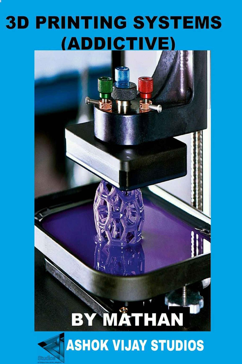
2 3D PRINTING (ADDICTIVE) SYSTEM -By MATHAN COPY RIGHT VIJAY STUDIOS 2017 A KINDLE PRODUCT ADDITIVE MANUFACTURING INTRODUCTION The competition in the world market for new products manufacturing is increased extremely now a days. It is very important bring new products to the market as early as possible before its competitors. Many of the processes involved in the design, test, manufacture and market of the products have been squeezed to bring products to the market swiftly, both in terms of material resources and time. The efficient use of such valuable resources calls for new tools and approaches. They are mainly technologydriven, usually involving the computer. This is mainly a result of the rapid growth and advancement in such technologies over the last few years. This book will give clear idea about various types of additive manufacturing technologies. WHAT IS ADDITIVE MANUFACTURING? Unlike subtractive manufacturing methods that start with a solid block of raw material and then cut away the unwanted to create required finished part, Additive manufacturing builds up part layer by layer from geometry and details in the CAD model. Additive Manufacturing has been declared as the first manufacturing revolution of the twenty first century. Additive manufacturing is the formalized term used to be called rapid prototyping and is popularly called 3D Printing. The term rapid prototyping (RP) is used in a different industries to describe a
3 process for rapidly creating a system or part representation before final release or commercialization. In a product development perspective, the term rapid prototyping was widely used to explain technologies which created physical prototypes directly from digital CAD model data. The term rapid prototyping is inadequate and in particular does not effectively describe more recent applications of the technology. Improvements in the quality of the output from these machines have meant that there is frequently a much closer to the product. Now many parts are manufactured directly in these machines using an additive approach, so it is not correct that label them as prototypes. In recent times formed Technical Committee within ASTM International agreed that new terminology should be adopted. This is still under debate still recently adopted ASTM compromise standards now use the term additive manufacturing instead of rapid prototyping. AM technology certainly extensively simplifies the manufacturing process of complex 3D objects directly from CAD model. Other manufacturing processes require a careful and detailed analysis of the part geometry to determine things like different features can be fabricated; tools and processes used, and additional fixtures may be required to complete the part. Additive Manufacturing needs only some basic dimensional details and a small amount of understanding about the AM machine works and the materials that are used to build the part. The key thing to how AM works is that parts are made by adding material in layer by layer; each layer is a thin cross-section of the part get from the CAD data and each layer must have a finite thickness to it and so the final part will be an approximation of the original data. If the layer thickness is, the closer the final part will be to the original. All AM machines up to date use is a layer-based approach, and the major ways that they differ are in the materials used, layers creating, and bonded technique to each other. This will determine factors like the accuracy of the final part, its mechanical and material properties, post processing requirement, size of the machine, production time cost for process and machine. This chapter will introduce the basic concepts of additive manufacturing and describe the AM process from design to application. WHAT ARE AM PARTS USED FOR? In this book you will find a wide variety of applications for every AM process. You will also understand that the number of applications is increasing as the processes develop and improve. Initially, this process was used particularly to create visualization
4 models for products as they were being developed. It is well-known that models can be much more helpful than drawings or renderings in understanding the plan of the designer when presenting the conceptual design. Drawings are quicker and easier to create, but the models are always required in the end to confirm the design. AM technology initially used for only simple model making purpose, but it has developed as material, quality and accuracy of the product is improved. Models were quickly engaged to supply information about 3 Fs of Form, Fit, and Function. The early models were used to help fully understand the shape and purpose of a design (Form). Accuracy improvement in the process meant that the sub assembly part were capable of being built to the tolerances necessary for assembly (Fit). Material properties improvement meant that parts could be accurately handled so that they can use for finally work (Function). WHY USE THE TERM ADDITIVE MANUFACTURING? By now, you should understand that the technology we are discussing is primarily the use of additive processes, adding materials layer by layer. The term additive manufacturing, or AM, seems to describe this quite well, but there are many other terms which are in use. Some of the process is not purely additive process, subtractive process is also combined. The term Additive Fabrication was popularized by Terry Wohlers, a famous industry consultant in this field. Many professionals use the term manufacturing to fabrication, but fabrication is associated with sheet metal bending and related processes. Thus the Professionals from these group often the use of the word fabrication for this industry. Additive manufacturing is starting to become widely used, and has also been adopted by Wohlers in his most current presentations and publications. THE BENEFITS OF AM The real benefit of Additive manufacturing is not only the speed of production, also the efficiency by means of lead time reduction. Unlike other manufacturing process, efficiency of AM remains constant when the volume of production is low, complex shape and other factors. AM requires few steps (design, build and remove), less efforts, easy to change alternation in existing design, any design can be build so there is no need of pre planning and analysis. If we change design slightly the number of steps of part build will increase in conventional method. Any parts (even complexity is more) can be build in a single step. The workstation remains clean and neat. There is no need of

5 planning for jigs and fixtures to part build. THE EIGHT STEPS IN ADDITIVE MANUFACTURE STEP 1: Conceptualization and CAD STEP 2: CONVERSION TO STL/AMF STEP 3: TRANSFER TO AM MACHINE AND STL FILE MANIPULATION STEP 4: MACHINE SETUP STEP 5: BUILD STEP 6: REMOVAL AND CLEANUP STEP 7: POST-PROCESSING STEP 8: APPLICATION The above sequence of steps is generally suitable to all AM technologies. There will be some variations dependent on the type of process and also on the design of the part. STEP 1: CONCEPTUALIZATION AND CAD The first step in any product development process is an idea about the product function and its look. Conceptualization can be many forms like description, sketches and representative model. If AM is to be used, the product description must be in a
6 digital form. AM technology is not possible without 3D CAD. The AM process must starts with 3D CAD detail. There are many software available for modelling (solidworks, CATIA, etc). Using this software required CAD model is generated of designer. Some older and poor CAD software creates solid models without fully enclosed. The best suitable software package is selected. Then the required design of CAD model is generated. STEP 2: CONVERSION TO STL/AMF Almost every AM technology uses the STL file format. STL stands for STereoLithograhy, which was the first commercial AM technology from 3D Systems. STL also stands for Standard Triangulation Language. It approximates the surfaces of the model with sets of triangular facets. The CAD system converts the 3D CAD model to STL file format automatically. The limitations of STL file are no units, material, colour and other feature information. These are rectified by new format called AMF. The complex and highly irregular geometry may result in triangle vertices that do not align properly. This may lead to gaps in the surface or sometimes it may lead to additional unwanted material included in the part. While the most of the errors are automatically detected and rectified in the software, there is a requirement of manual interference. STEP 3: TRANSFER TO AM MACHINE AND STL FILE MANIPULATION After STL file has been created and repaired, it can be sent to AM machine to part build. If we press Print button, the machines starts building. It should be possible to press a print button and the machine should build the part immediately. This is not regularly the case however and there may be a number of actions needed earlier to building the part. The first task is verify the part is correct. To view and manipulate the part AM system software usually has visualization tool. The user may desire to reposition the part or change the orientation to allow it to be built at a specific location within the machine. More than one part can be built in an AM machine at a time. This may be multiples of the same part or different part. STEP 4: MACHINE SETUP There is different type of AM machines available with setup parameters. The layer thickness, part orientation, position of part build and other process parameters are entered based on our requirement. The part builds time and production cost will varies with this parameters change. Variety of material can be used in some machines. Improper machine set up lead to poor quality of the final product. The operator must
7 check the part and support material is loaded sufficiently. Most of the machines automatically calculate the availability of the materials. STEP 5: BUILD After finishing machine set up the part build is started. This process is fully automated, few process are semi automated. The part build will be layer by layer adding technique, but the building process various with different AM process. This will continue until the final product is finished. There is no need of continuous monitoring the process. STEP 6: REMOVAL AND CLEANUP Once the part build finished, the part will required some of post processing. The part must be removed from the platform or removed from excess material. Support structures also must be removed. Some process has been developed to produce easy to remove it. For metal supports, band saw, a wire EDM machine, and/or milling equipment may be required to remove the part from the base plate and the supports from the part. Some operator skill is required to remove part and support, since mishandling of parts can result in damage to the part. The cleaning is required for Different AM parts. STEP 7: POST-PROCESSING Post-processing means the (usually manual) stages of finishing the parts for application purposes. This may involve some finishing operations like abrasive finishing, polishing and sandpapering, or application of coatings. Some applications may only need a minimum of post-processing. Other applications may need very careful handling of the parts to maintain good precision and finish. Some post-processing may involve thermal or chemical treatment of the part to attain final part properties. Different AM processes have different accuracy of finish, and thus machining to final dimensions may be necessary. Some components may require the use of infiltration and/or surface coatings to strengthen the final part. Other additional equipment, like polishing tubs or drying and baking ovens needed. STEP 8: APPLICATION After completing the post-processing, parts are ready to use. Although parts may
8 be made from similar materials to those available from other manufacturing processes (like casting and molding), parts may not behave as standard material specifications given. They may also need additional treatment before they are suitable for use. They may require priming and painting to give an acceptable surface finish and texture. The behaviour of the part may be better or worse for some purpose, but the designer made the decision for best process. They may also be required some assembly operation with other mechanical or electronic components to form a final model or product. DESIGN FOR ADDITIVE MANUFACTURING Part Orientation Orientation in which part has to be built in RM machine is very important step. Part orientation at the time of the built has the biggest impact on part functionality. It also has an impact on price because it determines the number of material layers is in the part. The amount of layers dictates run-time and the amount of support material needed. The part orientation should have the following characteristics. Maximize the number of perpendicular surface Maximize the number of up facing horizontal surface Maximize the number of holes with their axes in slicing direction Maximize the number of curved cross sections drawn in horizontal plane Maximize the area of base surface Minimize the number of sloped surface Minimize the total area of overhanging surfaces Minimize the number of trapped volumes SUPPORT STRUCTURE DESIGN Depending on the design application a support structure may be decomposed into three functional areas with different building strategies for practical applications. For an area connecting to part surfaces the support structure should be easily removable while proving sufficient support. The support structure for this area is often defined as sierras or needles with minimum contact with the part surface. The main support should be strong enough to withstand both vertical weight and horizontal disturbances. Support structure generation Parts are built layer-by-layer, every layers must be supported by something

9 underneath it. Features that are not directly supported by fundamental layers or the build platform are called unsupported overhangs. Example can be seen in the pictures. These features fails to print without support structure. A different strategies may be applied for areas between the main support and the platform for easy removal while providing a stable base support. The Structure should be designed such that its total weight is minimized. Thus, the three functional areas are, 1. Sierras or needles: connection between the main support and the part 2. Supports: the main support structure 3. Separators: connections between the main support and the platform 1.Gussets: gussets ( a single one or a set) are used to support lightweight overhanging areas during the part building process and attach to a vertical wall near the overhang areas. Gussets provide the optimal support for overhang areas while requiring minimal resources during the building process. The Supports are also easily identified during cleanup. 2. Projected feature edges: The edges of unsupported lightweight areas where gussets cannot reach are projected downwards to provide support. Projected feature edges

10 support the edges of the feature and provide excellent control against curling and war page. 3. Single Webs: Thin walls can be supported by single webs produced by projecting the center line along the narrow side of the thin walled feature. Cross members are added to provide stability of the support structure. 4. Webs: Large unsupported areas may be supported by various web structures; Contact of each support structures with vertical part walls should be avoided to protect the final part surface. To minimize support material consumption, perforated walls may be used in the web structure 5. Scaffolding: various scaffolding structures used in the construction and tissue engineering can also be designed as support structures for rapid prototyping. 6. Honeycomb: Other sophisticated support structures similar to the honeycomb style for hollowing master prototype models initially developed for Quick Cast 2.0 (Hague et al. 2001) may also be used as support Structures 7. Columns: For isolated small islands, column type support structures can be used. For large islands, columns defined by other web structures may also be used. 8. Zigzag and Perimeter support: The zigzag and perimeter support structure is most suited for FDM prototyping with a continuous path for each layer. For all the above mentioned Support structures the thickness of thin webs can be just a single cured line. SLICING After part orientation and support structure generation, the virtual model is divided into number of layers. Each layers information is passed to machine to move controller according to contour of the each layers. Smaller the slice thickness, part accuracy will be higher. Tool path generation

11 The direction and path in which material is deposited or sintered or glued in each layer is defined as tool path. Tool path influence on strength, material consumption and time required to fabricate the part. Tool path generally used in Additive manufacturing process is shown in figure. Once the slicing contour data is ready, one can start addressing process dependent issues for tool path generation. In particular, as most of the RP process is layer-based process, one can produce the tool path layer-by-layer starting from the bottom layer. TYPES OF TOOL PATH GENERATION Generally the tool path generation of many RP techniques can be classified in fallowing category. RASTER SCANNING PERIMETER SCANNING DIRECTIONAL SCANNING ZIGZAG TOOL PATH LINE BY LINE SCANNING AREA BY AREA SOLIDIFICATION BOUNDARY CUTTING TOOL PATHS RASTER SCANNING It refers to scanning along one coordinate axis for model solidification. This is the simplest path for RP. The scanning strategy can be applied to processes such as stereo lithography (SL), selective laser sintering (SLS).


12 PERIMETER SCANNING This approach can also be turned into a contouring approach with multiple parameters and their offsetting contours. The method is applicable to almost all RP technique is mainly for LOM. DIRECTIONAL SCANNING It is sometimes used to improve the mechanical properties of model fabricated in RP techniques. This scanning may be in certain orientation like 0, 45 and 90. This is basic pattern used for the TRI HATCH scanning style that was once used on SLA machine of 3D system. ZIGZAG TOOL PATH It is often used in FDM, 3D welding and other extruding type RP systems. This also used in drop-on-demand RP Process (3D ink jet Printing). This may be single or triple parameter zig-zag path.


13 LINE BY LINE SCANNING It is often used in inkjet printing process. (Thermo jet printer). Each layer is produced through single sweeping of a line component along the principle scanning direction. BOUNDARY CUTTING TOOL PATHS In LOM, a boundary cutting strategy is used. For cutting waste and supporting materials during the LOM process, a basic orthogonal xy- hatching pattern is often used. AREA BY AREA SOLIDIFICATION Photo-polymer based resin curing is an ideal example for this tool path. Here first mask is developed based on the sliced contours and the thin layer of photopolymer resin is then selectively solidified by exposing it to UV light. CLASSIFICATION OF AM
14 The Additive Manufacturing processes are classified based on raw material used. Liquid based Solid based Powder based NEW AM CLASSIFICATION SCHEMES Vat photopolymerization: processes that use a liquid photopolymer that is contained in a vat and processed by selectively delivering UV light or LASER energy to cure specific regions of a part layer. Sheet lamination: processes that deposit a layer of sheet form material at a time. Material jetting: processes ink-jet printing. Powder bed fusion: processes that use a container filled with powder that is processed selectively using LASER or Electron Beam energy source Material extrusion: processes that deposit a material by extruding it through a nozzle, while scanning the nozzle in a pattern of a part cross section to be produced. Binder jetting: processes where a binder is printed into a powder bed to form cross-sections of part. Directed energy deposition: processes that simultaneously deposit a material (powder or wire) and provide energy to cure that material through a single device.
15 LIQUID-BASED RAPID PROTOTYPING SYSTEMS Liquid-based rapid prototyping systems also called vat polymerization because most of it builds parts in a vat of photo-curable liquid resin, an organic resin that solidifies or cures by exposure to UV light. The UV light cures the resin near the surface, forming a hardened layer. When a layer of the part is formed, it is lowered by a control system to allow the next layer of resin to be similarly formed over it. This process will continue until the entire part is completed. The vat can then be drained and the part removed for post processing, if required. There are differences in this technique by the various vendors and they are dependent on the type of laser or light, method of exposure scanning, type of elevation, optical system used and type of liquid resin. STEREOLITHOGRAPHY APPARATUS (SLA) 3D Systems was started by Charles W.Hull and entrepreneur Raymond S. Freed in Amongst all the commercial RP systems, the Stereo lithography Apparatus (SLA) is the lead the way with its first commercial system marketed in Stereolithography is an additive manufacturing or 3D printing technology used for producing models, prototypes, patterns by curing a photo-reactive resin with a UV laser or another similar power source. Principle The SLA process is based on the following principles: (1) Parts are built from a photo-curable liquid resin which cures when exposed to a laser beam or light by photo-polymerization process, which scans across the surface area of the resin. (2) The part building is done layer by layer, each layer being scanned by the light or laser scanning system and controlled by an elevation mechanism which lowers in steps at the completion of each layer.

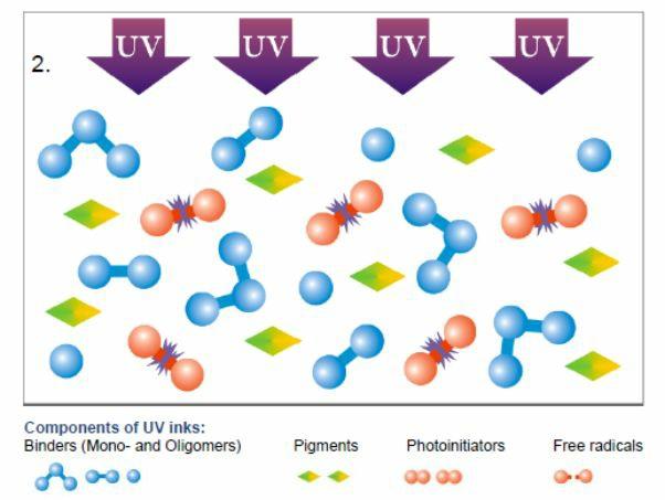
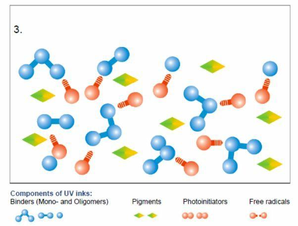
16 Photopolymerization Polymerization is the process of linking small monomers into chain-like larger polymers. When the chain-like polymers are linked further to one another, a cross-linked polymer is formed. Photo-polymerization is polymerization initiated by a photochemical process stimulated by source energy from the radiation. A photopolymer is a polymer which changes its properties when exposed to UV light. Hardening of the material occurs as a result of cross-linking when exposed to UV light. After curing, it hardens the liquid to solid state. Oligomers: This material consists of chain like, long, chemicallyreactive molecules which give the final solid its mechanical and other properties. Range of 50-80% of the total weight. Monomers: Monomers may typically constitute 10-40% of the photopolymer. Photoinitiators: Photoinitiators are molecules that can be divided into two or more parts by exposure to light. It comprises just a few percent of the photopolymer.
17

18 Process Stereolithography process creates 3D plastic objects directly from CAD data. The process starts from photo-curable liquid resin is filled in a vat and the elevator table set just below the surface of the liquid resin. The operator loads a 3D CAD solid model file into the system. Supports structures are designed to support the part during building. The translator converts the 3D CAD data into a STL file format. The control unit slices the model and support into many of cross section layers from to 0.5 mm thick. Then the computer-controlled optical scanning system direct and spot the laser beam to solidifies a 2D cross-section corresponding to the slice on the surface of the photo-curable liquid resin. The elevator table drops down enough to cover the solid polymer by another the liquid resin layer. Then a levelling wiper moves across the surfaces to spread the resin to the next layer on the surface. The laser then draws the next layer. This process continues the part building from bottom to up, until the system completes the part. The part is then taken out of the vat and cleaned of excess polymer.

![[250*250*250]-](/docs-images/77/75018869/images/19-1.jpg "[737*635*533] Vat")
19 Process parameters Minimum build envelope [250*250*250]- [737*635*533] Vat capacity 8.5 l-247 l
20 Laser Solid state Nd:YVO4(Neodymium-doped yttrium orthovanadate) Power Beam diameter Slicing thickness 100mW to 1000mW Std: 0.25mm-0.13 HR mode: mm
21

22 Advantages: The main advantages of using SLA are: Good accuracy. The SLA has good accuracy and can thus be used for many
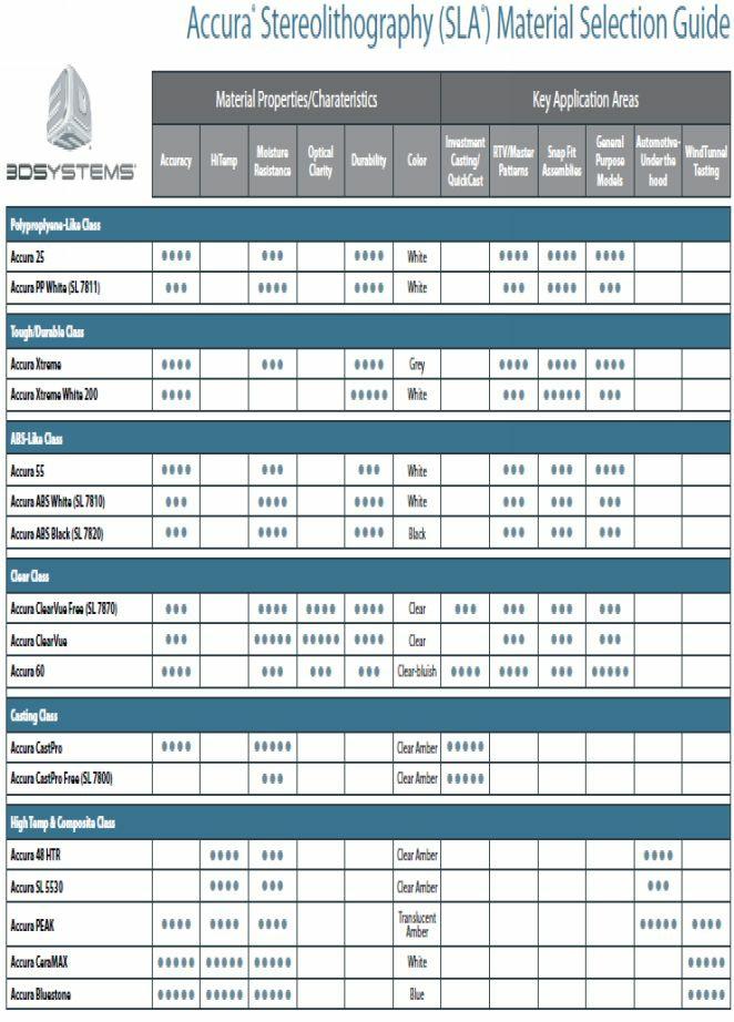
23 application areas. Good user support. The computerized process serves as a good user support. Wide range of materials. There is a wide range of materials, from general-purpose materials to specialty materials for specific applications. Round the clock operation. The SLA can be used continuously and unattended round the clock. Build volumes. The different SLA machines have build volumes ranging from small to large to suit the needs of different users. Surface finish. The SLA can obtain one of the best surface finishes amongst RP technologies. Disadvantages: The main disadvantages of using SLA are: Requires post-processing. Requires support structures. Requires post-curing. Applications The SLA technology provides manufacturers with cost correct methods for reducing time to market, reducing product development costs, gaining greater control of their design process and improving product design. The applications include: Models for conceptualization, packaging and presentation. Prototypes for design, analysis, verification and functional testing. Parts for prototype tooling and low volume production tooling. Patterns for investment casting, sand casting and molding. Tools for fixture and tooling design, and production tooling.
24
25 SOLID-BASED RAPID PROTOTYPING SYSTEMS Solid-based rapid prototyping systems are altered from the liquid-based photocuring systems. They are also different from one another within it, though some of them do use the laser in the process. The common feature among them is that they all utilize solids (in one form or another) as the primary medium to create the prototype. SOLID GROUND CURING (SGC) Solid ground curing (SGC) is a photo polymer based additive manufacturing technology used for producing models, prototypes, patterns, and production parts. In this process layer geometry is produced is by passing UV light through a mask. As the basis of solid ground curing is the exposure of each layer of the model by means of a lamp through a mask. This method offered good accuracy and a very high fabrication rate. The Solid Ground Curing (SGC) System is produced by Cubital Ltd. Cubital Ltd. s operations began in 1987 as a spin-off from Scitex Corporation and commercial sales began in Principle: SGC process is based on Curing of photopolymer layer by layer. Curing is a term refers to the toughening or hardening of a polymer material by cross-linking of polymer chains, brought about by electron beams, heat, light or chemical additives. Photopolymer changes its properties when exposed to light. These changes are often manifested structurally like hardening of the material occurs as a result exposed to light create cross-linking. Curing in SGC: Typically a photopolymer consists of a mixture of multifunctional monomers, photo initiators and oligomers in order to achieve the desired physical properties. Hardening of the material occurs as a result of cross-linking in mixture when exposed to light.
26 Solid Ground Curing Process:

27 1. The cross section of each layer is calculated based on the geometric model of the part and the desired layer thickness. 2. The optical mask is created conforming to each cross section of layer. 3. After leveling, the part building platform is enclosed with a thin layer of liquid photopolymer. 4. The mask corresponding to the layer is located over the surface of the liquid resin, and the resin is exposed to a high-power UV light. 5. The remaining liquid is removed from the work piece by an aerodynamic wiper. 6. A layer of melted wax is spread over the work piece to fill voids. Then the wax is solidified by applying a cold plate to it. 7. The layer surface is trimmed to the required thickness by a milling process. 8. The current work piece is covered with a thin layer of liquid polymer and step 4 to 7 are repeated for each successive upper layer until the uppermost layer has been processed. 9. The wax is removed by melting after the completion of the part. Steps: 1. Preparation of Mask 2. Applying liquid photopolymer layer 3. Mask positioning and exposure of layer

28 4. Uncured polymer removed from surface 5. Wax filling 6. Milling for flatness and thickness. SGC Process Specification: Build Size Achievable Accuracy X-Y Resolution Geometric Complexity Models up to 500*350*500 mm 0.1% (Measured between targets through the material) mm ( inch) Unlimited
29 Z Resolution (Variable Layer mm ( inch) Thickness) Layer build speed photopolymers 70sec Acrylic and epoxy resin Advantages No post curing of parts is required No supports are required Good dimensional accuracy Complexity is unlimited It allows nesting of parts SGC has a large build area It s a fastest fabrication process when compared to other RP process Disadvantages Initial cost is very high Large area is required for installation Excessive waste of wax and resin It has greatest material limitation with only acrylic and a single epoxy resin Application The applications of SLA can generally be divided to four areas General Applications: Conceptual design presentation, engineering testing, design proofing, functional analysis, integrating and fitting,, exhibitions and preproduction sales, market research, and inter professional communication. Casting Applications: Investment casting, sand casting, and rapid tool free manufacturing of plastic parts. Mold and Tooling: Silicon rubber tooling, epoxy tooling, spray metal tooling, acrylic tooling and plaster mold casting. Medical Imaging: Diagnostic, surgical, operation and reconstruction planning and custom prosthesis design and so forth.
 technology.")
30 FUSED DEPOSITION MODELING (FDM) FDM is a solid based rapid prototyping technique which uses thermoplastics to print 3d models. FDM is otherwise known as plastic jet printing (PJP). Stratasys Inc. was started in 1989 and has developed most of the industry s products based on the Fused Deposition Modelling (FDM) technology. The technology was first developed in 1988 by Scott Cramp and the patent was awarded in 1992 in the US. FDM uses the extrusion process to build 3D models. Reasons to choose FDM Eco-friendly Good Surface finish Functional parts with greater stability Small series of quality parts Principle A type of plastic is extruded from the heated nozzle. The temperature of the nozzle is controlled by the computer to allow for even extrusion. The material exits the nozzle with a liquid consistency. The movement of the nozzle varies depending upon the shape of the printing component. Materials Used Modeling material: The most common printing material for FDM is
.")
31 acrylonitrile butadiene styrene (ABS) which is derived from fossil fuels, Along with ABS, some FDM machines also print in other thermoplastics, like polycarbonate (PC) or polyetherimide (PEI). Support materials: which acts as scaffolding are brittle thermoplastics, like polyphenylsulfone (PPSF). ABS (acrylonitrile butadiene styrene): ABS plastics are used largely for mechanical purposes because of its high impact strength. ABS plus: derived from ABS, 50-70% more efficient. PPSF(polyphenylsulfone): has the greatest heat and chemical resistance, can with higher temperatures up to 304 C Parts of FDM Extrusion nozzle: This is an important part of the machine from which metal gets heated up and liquified. There are two nozzles for two types of material. Stepper motors: The stepper motor helps to move the nozzle precisely according to the CAM (Computer-Aided Manufacturing) program code which defines the path of the motion of nozzle


32 Drive wheels: The drive wheels will provide the required feed for the filaments so that it properly moves. Platform: This is the base on which fused deposition model is produced. Process

33 Pre-Processing First, the CAD file is created in AutoCad or another design program. The model needs to be imported into Stratasys software, Insight. The software converts the.stl file into horizontal layers mathematically, creating the required supports. Insight creates tool paths required for the extrusion head. Production ABS material feeds into the temperature-controlled FDM extrusion head, where it is heated to a semi-liquid state. When the layer is finished, the head moves up in Z direction to the next layer. Each layer is extruded with precision, and the layers are bonded and solidified. The designed 3D model of the object becomes a solid part. Post-processing Removal of supports from part Removal of part from platform Cleaning of part (rinsing ) Finishing part Process Parameters:

34 Advantages Easy to material change Wide variety of materials available Low maintenance costs No toxic materials Tolerance of +/ " overall No supervision required Very compact size Thin parts produced fast Disadvantages Slow process Unpredictable shrinkage Restricted accuracy Application FDM models can be used in the following general applications areas: (1) Models for conceptualization and presentation. Models can be marked, drilled, painted and sanded and thus can be finished to be approximately like the actual product. (2) Prototypes for design, analysis and functional testing. (3) Masters and Patterns for tooling. This model can be used as patterns for
35 molding, sand casting and investment casting. (4) Aerospace Industries, Automotive Industries, Commercial Industries, Industrial Components, Medical field. (5) Automotive Companies such as BMW, Hyundai uses FDM throughout their product development, prototyping and manufacturing processes (6) The aim of 3d-printing industries is to make the machine portable and to get coupled with every desktop as like 2D printers. LAMINATED OBJECT MANUFACTURING (LOM) Cubic Technologies was established in December 2000 by Michael Feygin, the inventor who developed Laminated Object Manufacturing (LOM). In 1985, Feygin set up the original company, Helisys Inc., to market the LOMTM rapid prototyping machines. Principle Parts are built, layer-by-layer, by laminating each layer of paper or other sheetform materials and the contour of the part on that layer is cut by a CO2 laser. Each layer of the building process contains the cross-sections of one or many parts. The next layer is then laminated and built directly on top of the laser-cut layer. The Z-control is activated by an elevation platform, which lowers when each layer is completed, and the next layer is then laminated and ready for cutting. The Z-height is then measured for the exact height so that the corresponding cross sectional data can be calculated for that layer. No additional support structures are necessary, which are cross-hatched for later removal, act as the support. Process
36 The Laminated Object Manufacturing (LOM) process is an automated fabrication method in which a 3D object model is constructed from a solid CAD representation by consecutively laminating the part cross-sections. The process consists of three phases: pre-processing; building; post-processing. Pre-processing The pre-processing phase comprises several operations. The initial steps include generating an image from a CAD-derived STL file of the part to be manufactured, sorting input data, and creating secondary data structures. These are fully automated by LOM Slice, the LOM system software, which calculates and controls the slicing functions. Orienting and merging the part on the LOM system are done manually. These tasks are aided by LOM Slice, which provides a menu-driven interface to perform transformations (e.g., translation, scaling, and mirroring) as well as merges. Building In the building phase, thin layers of adhesive-coated material are sequentially bonded to each other and individually cut by a CO2 laser beam. The build cycle has the following steps: (1) LOM Slice creates a cross-section of the 3D model measuring the exact height of the model and slices the horizontal plane accordingly. Then the software images cross-hatches which define the outer perimeter and it converts these excess materials into a support structure. (2) The computer generates precise calculations that guide the focused laser beam to cut the crosshatches, the cross-sectional outline, and the model s perimeter. The laser beam power is designed to cut exactly the thickness of one layer of material at a time. Once the perimeter is burned, everything within the model s boundary is removed from the remaining sheet. (3) The platform with the stack of already formed layers descends and a new layer section of material advances. Then the platform ascends and the heated roller laminates the material to the stack with a single reciprocal motion, thereby bonding it to the previous layer.
 This sequence continues until all the layers are built. The product removed from the LOM machine as a completely covered rectangular block containing the part.")
37 (4) The vertical encoder measures the stack height and relays the new height to LOM Slice, which calculates the cross section for the next layer as the laser cuts the model s current layer. (5) This sequence continues until all the layers are built. The product removed from the LOM machine as a completely covered rectangular block containing the part. Post-processing The last phase is post-processing. It includes separating the part from its support material and finishing it. (1) The metal platform, house to the recently created part, is removed from the LOM machine. A forklift may be required to remove the larger and heavier parts from the LOM. (2) Normally a hammer and a putty knife are required to separate the LOM block from the platform. However, a live thin wire may also be used to cut through the doublesided foam tape, that serves as the connecting point between the platform and the LOM stack. (3) The surrounding wall frame is lifted off the block to expose the crosshatched pieces of the unwanted excess material. Then Crosshatched pieces may be detached from the part using wood carving tools. After the part is extracted from surrounding
38 crosshatches the wood like LOM part can be finished. Traditional model-making finishing techniques, such as painting, sanding, polishing, etc. can be applied. After the part has been separated it is be sealed immediately with urethane, silicon or epoxy spray to prevent moisture absorption and expansion of the part. If essential, LOM parts can be machined by milling, drilling, and turning. Materials Potentially, any sheet material with adhesive backing can be used in Laminated Object Manufacturing. It has been established that metals, plastics, and even ceramic tapes can be used. However, the most popular material has been Kraft paper with a polyethylenebased heat seal adhesive system because it is cost effective, widely available, and environmentally benign. To maintain uniform lamination across the complete working envelope it is critical that the temperature stay constant. A temperature control system, with closedloop feedback, conform the system s temperature remains constant, regardless of its surrounding environment. Advantages The main advantages of using LOM technology are as follows: Wide variety of materials. Fast build time. High precision. Support structure. Post-curing. Disadvantages The main disadvantages of using LOM are as follows: Precise power adjustment. Fabrication of thin walls. Integrity of prototypes. Removal of supports. Applications (1) Visualization. Many companies use LOM s ability to produce exact dimensions of a required product purely for visualization.
39 (2) Form, fit and function. LOM parts lend themselves well for performance estimation and design verification. In low-stress environments LOM parts can withstand basic tests, giving manufacturers the chance to make changes as well as evaluate the aesthetic property of the prototype. (3) Manufacturing: casting, investment casting, sanding casting, silicon rubber mold, injection molding vacuum forming and spray metal molding. (4) Rapid tooling. Two part negative tooling is simply created with LOM systems. Since the material is solid and inexpensive, bulk difficult tools are cost effective to produce. POWDER-BASED RAPID PROTOTYPING SYSTEMS SELECTIVE LASER SINTERING (SLS) The SLS process was developed and patented in the 1980 s by Carl Deckard and his mechanical engineering professor, Joe Beaman. The technology was patented in 1989 and was originally sold by DTM Corporation. DTM was acquired by 3D Systems in SLS involves the use of a high power laser (for example, a carbon dioxide laser).unlike other additive manufacturing technologies, SLS does not require support structures. Principle Sintering is the process of forming a solid mass of material by heat and/or pressure without melting it to the point of liquefaction. Additive manufacturing, or 3D printing, is the process of turning digital designs into three-dimensional objects. Selective Laser Sintering (SLS) is an additive manufacturing technique that utilizes a laser as the power source to sinter powdered material, aiming the laser automatically at points in space defined by a 3D model, binding the material together to create a solid structure.
 5. This process fuses the particles in the powder together into a solid form. 6.")
40 Process 1. An object printed with an SLS machine starts as a CAD file 2. CAD files are converted to.stl format 3. The powdered materials are dispersed in a thin layer on top of the build platform 4. A laser, which is controlled by a computer heats the powder either to just below its boiling point (sintering) 5. This process fuses the particles in the powder together into a solid form. 6. Once the initial layer is formed, the platform of the SLS machine drops usually by less than 0.1mm exposing a new layer of powder 7. This process continues again and again until the entire object has been printed. 8. When the object is fully formed, it is left to cool for 12 to 24 hours in the machine before being removed. SELECTIVE LASER SINTERING-SPECIFICATIONS Material type: Materials: Powder (Polymer) Thermoplastics such as Nylon, Polyamide, and

41 Polystyrene; Elastomers; Composites Max part size: Min feature size: Min layer thickness: Tolerance: Surface finish: Build speed: Applications: 560 x 560 x 760 mm..127mm.102mm.254mm Average Fast, Rapid tooling patterns, High heat applications, Form/fit testing, Functional testing, Less detailed parts, Parts with snap-fits & living hinges

42 KEY DIFFERENCES BETWEEN SLS AND SLA Prototype strength: SLS prototypes are more durable and stronger than SLA prototypes. Material properties: SLS allows product prototypes to be produced with material properties similar to those of injection moulded prototypes. Surface finish: SLS prototypes have a powdery finish, unlike SLA prototypes. Machining properties: It is easier to machine prototypes formed using SLS than those created using SLA. Material choice: In several different thermoplastic materials SLS allows for product prototypes Metal product prototypes: SLS can be used to create metal prototype parts using metallic powder in the laser sintering process. Post-completion processing: There is typically very little (if any) processing required after the SLS process is completed. ADVANTAGES It produces the toughest components compared to other RP techniques.
43 A wide range of materials can be used, including metal (DMLS), plastic, ceramics, wax, nylon, elastomers, and polycarbonate. No post-curing processes are needed. A relatively short production time (approximately 1 in/h) is possible. No additional support is required during the building process. Different parts can be built on top of others. Leftover powder can be reused with some ratio. Disadvantages A rough surface finish is produced due to the stair-case effect. The time needed to heat up the powder and cool down the model after it has been completed is approximately 8 to 10h. Toxic gases are produced especially when plastic materials are fused. Components are less detailed than those produced by stereo lithography due to a high processing temperature and high shrinkage. Application Due to its capability to easily build very complex geometries directly from digital CAD data, SLS technology is in broad use around the world. It is increasingly being used in limited-run manufacturing to produce end-use parts. Various industries like Aerospace, Automotive, Industrial, Dental Copings, Surgical Tools Medical Instruments It is used in art that is less expected and rapidly growing application of SLS. LASER ENGINEERED NET SHAPING (LENS) Optomec Inc. was incorporated in Since 1997, Optomec has focused on commercializing a direct fabrication process, the Laser Engineered Net Shaping (LENS) process initially developed by Sandia National Laboratories. Its first commercial system is delivered to Ohio State University.
44 Principle The LENS process is based on the following principles: (1) A high powered Nd:YAG laser beam focused onto a metal substrate creates a molten pool on the substrate surface. Powder is then injected into the molten pool to increase material volume. (2) A printing motion system moves a platform horizontally and laterally as the laser beam traces the cross-section of the part being created. After formation of a layer of the part, the machine s powder delivery nozzle moves upwards prior to building next layer. Process The LENS process builds components in an additive manner from powdered metals using a Nd:YAG laser to fuse powder to a solid as shown in Figure. It is a freeform metal fabrication process in which a fully dense metal component is formed. The LENS process comprises of the following steps: (1) A deposition head supplies metal powder to the focus of a high powered Nd:YAG laser beam to be melted. This laser is typically directed by fibre optics or precision angled mirrors. (2) The laser is focused on a particular spot by a series of lenses, and a motion system below the platform moves horizontally and laterally as the laser beam traces the cross-section of the part being produced. The manufacturing process takes place in a low pressure argon chamber for oxygen-free operation in the melting zone, ensuring that fine bond is accomplished. (3) When a layer is completed, the deposition head moves up and continues with the next layer. The process is repeated layer by layer until the part is completed. The entire process is usually enclosed to isolate the process from the atmosphere. Generally the prototypes need additional finishing, but are fully dense products with good grain formation.

45 Advantages Superior material properties. The LENS process is capable of producing fully dense metal parts. Metal parts produced can also include embedded structures and superior material properties. The microstructure produced is also relatively good. Complex parts. Functional metal parts with complex features are the forte of the LENS system. Reduced post-processing requirements. Post-processing is minimized, thus reducing cycle time. Disadvantages Limited materials. The process is currently narrowly focused to produce only metal parts. Large physical unit size. The unit requires a relatively large area to house. High power consumption. The laser system requires very high wattage. Applications The LENS technology can be used in the following areas: Build mold and die inserts Produce functionally gradient structures Producing titanium parts in racing industry
46 Fabricate titanium components for biological implants THREE-DIMENSIONAL PRINTING (3DP) Z Corporation was incorporated in 1994 by Hatsopoulos, Walter Bornhost, Tim Anderson and Jim Brett. In 1997, it commercialized its first 3D Printer, the ZTM402 System based on three-dimensional technology (3DP). This technology was invented and patented at the Massachusetts Institute of Technology (MIT). Principle 3D printing creates parts by adhesive bonding. Layer is created by adding another layer of powder. When the binder ink impinges on the powder layer - spherical aggregates of binder and powder particles are formed. The binding energy for forming solid is given by binder droplets. Capillary force aggregates including previous layer to merge. This will result in solid model. Process (1) The machine spreads a layer of powder from the feed box to cover the surface of the build piston. The printer then prints binder solution onto the loose powder, forming the first cross-section layer. For monochrome parts, Z406 colour printer uses all four print heads to print a single-coloured binder. For multi-coloured parts, each of the four print heads deposits a different colour binder, mixing the four colour binders to produce a spectrum of colours that can be applied to different regions of a part. (2) The powder is glued together at where the binder is printed. The remaining powder remains loose and act as supports that will be printed above this layer. (3) When one layer is completed, the build piston is lowered one step, a new layer of powder is spread over its surface, and the process is repeated. The part grows layer by layer in the fabricate piston until the part is fully completed. Finally the build piston is raised and the loose powder is vacuumed, removing the complete part. (4) For a design review, parts can be left raw. To quickly produce a more strong
 Simple to operate: The office compatible Corp.")
47 model, parts can be dipped in wax. And also that can be sanded, painted, finished and, the part can be infiltrated with a resin or urethane. Advantages (1) Versatile. Parts are presently used for the automotive, aerospace, education, packaging, footwear, telecommunications and medical industries. (2) Simple to operate: The office compatible Corp. System is straightforward to operate and does not require a selected technician to build a part. It is dependable and reliable 3D printer. (3) No wastage of materials. Powder that is not printed during the process can be reused. (3) High speed. Each layer is printed in seconds, reducing the prototyping time of a hand-held part to 1 to 2 hours. (5) Colour: Enables complex colour schemes in RP-ed parts from a full 24-bit palette of colours. Disadvantages (1) Limited materials. The materials available are only starch and plaster-based materials, with the added choice to infiltrate wax. (2) Limited functional parts. The parts built are much weaker than SLS, thereby limiting the functional testing capabilities.
48 (3) Poor surface finish. Parts built by 3D printing have a relatively poorer surface finish and post-processing is frequently required. THE SHAPE DEPOSITION MANUFACTURING PROCESS The Shaped Deposition Manufacturing process (SDM), first developed by Prof. Fritz Prinz and his group at Carnegie Mellon University and later Stanford University. Although most rapid prototyping processes based on the discretized layer by layer process are able to manufacture almost any complex shape and form, they suffer from the very process of discretization in terms of geometric accuracies surface finish as well as surface finish. SDM is a rapid prototyping process that overcomes these problems by combining the flexibility of the additive layer manufacturing process with the accuracy and precision attained with the subtractive CNC machining process. Principle The SDM process is a rapid prototyping process that combines the advantages of layer-by-layer manufacturing with the advantages of precision material removal (subtractive) process. Process Materials for the individual segments of the part are first deposited at the deposition station to form the layer of the part. One of the several deposition processes is a weld-based deposition process called micro-casting, and the product is a near-net shape deposition of the part for that layer. Then the part is transferred to the shaping station, typically a five-axis CNC machining centre where material is removed to form the desired shape of the part. After the shaping station, the part is transferred to a stress relief station, such as shot-penning, to relieve and control residual stress build up due to the thermal process during deposition and machining. Then the part is transferred back to the deposition station where complementary

49 shaped, sacrificial support material is deposited to support the part. The support material or part material deposition sequence is dependent on the geometry of the part. The process is repeated until the part is complete, after which, the sacrificial support material is removed and the final part is revealed. Advantages and Disadvantages The advantages of Shape Deposition Manufacturing are as follows: Direct creation of functional metal shapes Variable layer thickness Ability to build heterogeneous structures. In addition to the rapid prototyping of complex shapes, the SDM process is also able to produce multimaterial structures and it also allows pre-fabricated components to be embedded within the built shapes. Ease of creating undercut features. Wide variety of materials. The process is capable of using a wide variety of materials, including metals stainless steel, photo-curable plastics, steel alloys, thermoplastics, ceramics, waxes etc Disadvantages
Design Analysis Process
 Prototype Design Analysis Process Rapid Prototyping What is rapid prototyping? A process that generates physical objects directly from geometric data without traditional tools Rapid Prototyping What is
1.8.3 Haptic-Based CAD 1.9 About this Book 1.10 Exercises References Development of Additive Manufacturing Technology
 Contents 1 Introduction and Basic Principles 1 1.1 What Is Additive Manufacturing? 1 1.2 What Are AM Parts Used for? 3 1.3 The Generic AM Process 4 1.3.1 Step 1: CAD 4 1.3.2 Step 2: Conversion to STL 4
3D Printing Technologies for Prototyping and Production
 3D Printing Technologies for Prototyping and Production HOW TO LEVERAGE ADDITIVE MANUFACTURING TO BUILD BETTER PRODUCTS ADDITIVE MANUFACTURING CNC MACHINING INJECTION MOLDING Architects don t build without
Prototypes on demand? Peter Arras De Nayer instituut [Hogeschool voor Wetenschap en Kunst]
![Prototypes on demand? Peter Arras De Nayer instituut [Hogeschool voor Wetenschap en Kunst]](/thumbs/78/77202330.jpg "Prototypes on demand? Peter Arras De Nayer instituut [Hogeschool voor Wetenschap en Kunst]") Prototypes on demand? Peter Arras De Nayer instituut [Hogeschool voor Wetenschap en Kunst] Pressure on time to market urges for new ways of faster prototyping. Key words: Rapid prototyping, rapid tooling,
Prototypes on demand? Peter Arras De Nayer instituut [Hogeschool voor Wetenschap en Kunst] Pressure on time to market urges for new ways of faster prototyping. Key words: Rapid prototyping, rapid tooling,
Visual Imaging in the Electronic Age
 Visual Imaging in the Electronic Age ART 2107, ARCH 3702, CS 1620, ENGRI 1620 3D Printing October 20, 2015 Prof. Donald P. Greenberg dpg5@cornell.edu Types of 3D Printers Selective deposition printers
The Additive Manufacturing Gold Rush. Dream or Reality?
 The Additive Manufacturing Gold Rush Dream or Reality? Where s the Rush? Source: Gartner (July 2014) The Additive Manufacturing Gold Rush Tools of the Trade Additive Manufacturing (AM) Basics CAD Solid
Visual Imaging in the Electronic Age
 Visual Imaging in the Electronic Age ART 2107, ARCH 3702, CS 1620, ENGRI 1620 3D Printing November 6, 2014 Prof. Donald P. Greenberg dpg5@cornell.edu Types of 3D Printers Selective deposition printers
DIRECT METAL LASER SINTERING DESIGN GUIDE
 DIRECT METAL LASER SINTERING DESIGN GUIDE www.nextlinemfg.com TABLE OF CONTENTS Introduction... 2 What is DMLS?... 2 What is Additive Manufacturing?... 2 Typical Component of a DMLS Machine... 2 Typical
Additive Manufacturing. amc.ati.org
 Additive Manufacturing amc.ati.org Traditional Tooling 356-T6 lever casting for DSCR Wood pattern on matchboard Additive Manufacturing (AM) A new term but the technology is almost three decades old Formerly
A customer requiring anonymity was able to procure the casting it needed at a lower cost and lead time than its previous fabrication.
 Rapid Tooling Opens New Diecasting Doors Think diecasting tooling will ruin your lead times? Think again. North American Die Casting Association, Wheeling, Illinois Manufacturers seeking a competitive
Applications of FFF in The Metal Casting Industry
 Applications of FFF in The Metal Casting Industry Rui Jiang, Wanlong Wang, James G. Conley Department of Mechanical Engineering Northwestern University Evanston, ll., 60208 Abstract Fast Freeform Fabrication
Classification of Metal Removal Processes and Machine tools. Introduction to Manufacturing and Machining
 Classification of Metal Removal Processes and Machine tools Introduction to Manufacturing and Machining Production Engineering covers two domains: (a) Production or Manufacturing Processes (b) Production
MANUFACTURING TECHNOLOGY
 MANUFACTURING TECHNOLOGY UNIT III THEORY OF METAL CUTTING Broad classification of Engineering Manufacturing Processes. It is extremely difficult to tell the exact number of various manufacturing processes
3D Printing Processes and Printing Materials
 3D Printing Processes and Printing Materials Introduction to 3D Printing Three-dimensional (3D) printing in recent years has become the main focus of public and media attention as a technology has at last
University of Wisconsin-Stout
 Technical Innovations: The Expansion of Rapid Prototyping Autumn Price University of Wisconsin-Stout February 2010 Introduction The next time you break, say, a lens cover for your camera or a case for
RPT/RT BUDAPEST UNIVERSITY OF TECHNOLOGY AND ECONOMICS FACULTY OF MECHANICAL ENGINEERING DEPARTMENT OF POLYMER ENGINEERING
 B4 BUDAPEST UNIVERSITY OF TECHNOLOGY AND ECONOMICS FACULTY OF MECHANICAL ENGINEERING DEPARTMENT OF POLYMER ENGINEERING RPT/RT SMALL SERIES MANUFACTURING OF POLYMER PRODUCTS HTTP://WWW.PT.BME.HU LOCATION
Rapid Prototyping: An Explorative Study on Its Viability in Pottery Production (Sub-Theme:17)
") Rapid Prototyping: An Explorative Study on Its Viability in Pottery Production (Sub-Theme:17) Ab. Aziz Shuaib (aziz@umk.edu.my) Faculty of creative Technology and Heritage, University Malaysia Kelantan
Rapid Prototyping: An Explorative Study on Its Viability in Pottery Production (Sub-Theme:17) Ab. Aziz Shuaib (aziz@umk.edu.my) Faculty of creative Technology and Heritage, University Malaysia Kelantan
Polyjet technology applications for rapid tooling
 DOI: 10.1051/ matecconf/20171120301 1 Polyjet technology applications for rapid tooling Razvan Udroiu *, and Ion Cristian Braga Transilvania University of Brasov, Department of Manufacturing Engineering,
Current status and future prospects of laser stereolithography. Today s talk:
 Current status and future prospects of laser Industrial application [26-1]#049 HAGIWARA, Tsuneo CMET Inc. E-mail: hagi@cmet.co.jp personal website: http://www.urban.ne.jp/home/hagi Today s talk: background
Two Categories of Metal Casting Processes
 Two Categories of Metal Casting Processes 1. Expendable mold processes - mold is sacrificed to remove part Advantage: more complex shapes possible Disadvantage: production rates often limited by time to
Introduction to Manufacturing Processes
 Introduction to Manufacturing Processes Products and Manufacturing Product Creation Cycle Design Material Selection Process Selection Manufacture Inspection Feedback Typical product cost breakdown Manufacturing
ON-DEMAND PARTS MANUFACTURING. Quickparts
 ON-DEMAND PARTS MANUFACTURING Quickparts On-demand parts manufacturing services Using our additive and traditional manufacturing technologies, bring your design to life and create real functional end-use
The third dimension. This article is supported by...
 The Wild Format guides are intended to expand awareness and understanding of the craziness that can be created on wide format digital printing devices, from floors to lampshades and everything in between.
International Journal of Advance Engineering and Research Development. 3D Printing for Different Casting Patterns
 Scientific Journal of Impact Factor (SJIF): 4.72 International Journal of Advance Engineering and Research Development Volume 4, Issue 8, August -2017 3D Printing for Different Casting Patterns B.Lakshmisai
CREATE PROJECT Edit Printer. Tutorial_V2 - Updated: 13,0600,1489,1629(SP6)
") CREATE PROJECT Tutorial_V2 - Updated: 13,0600,1489,1629(SP6) In this exercise, we will learn how to edit the printer! Notice/ Remember Left mouse button name is "pick" Middle mouse button name is "Exit"
CREATE PROJECT Tutorial_V2 - Updated: 13,0600,1489,1629(SP6) In this exercise, we will learn how to edit the printer! Notice/ Remember Left mouse button name is "pick" Middle mouse button name is "Exit"
(( Manufacturing )) Fig. (1): Some casting with large or complicated shape manufactured by sand casting.
) Fig. (1): Some casting with large or complicated shape manufactured by sand casting.") (( Manufacturing )) Expendable Mold Casting Processes: Types of expendable mold casting are: 1 ) Sand casting. 2 ) Shell molding. 3 ) Vacuum molding. 4 ) Investment casting. 5 ) Expanded polystyrene process.
(( Manufacturing )) Expendable Mold Casting Processes: Types of expendable mold casting are: 1 ) Sand casting. 2 ) Shell molding. 3 ) Vacuum molding. 4 ) Investment casting. 5 ) Expanded polystyrene process.
3D PRINTER MATERIALS GUIDE
 3D PRINTER MATERIALS GUIDE The two primary technologies used for desktop 3D printing are fused deposition modeling () and stereolithography (). For those new to 3D printing, technology feeds melted plastic
Ink-Jet Three-dimensional Printing of Photopolymers: A Method of Producing Novel Composite Materials
 Ink-Jet Three-dimensional Printing of Photopolymers: A Method of Producing Novel Composite Materials Eduardo Napadensky, Objet Geometries Ltd., Israel Current additive type manufacturing technologies such
Chapter 1 Sand Casting Processes
 Chapter 1 Sand Casting Processes Sand casting is a mold based net shape manufacturing process in which metal parts are molded by pouring molten metal into a cavity. The mold cavity is created by withdrawing
University of Arizona College of Optical Sciences
 University of Arizona College of Optical Sciences Name: Nachiket Kulkarni Course: OPTI521 Topic Plastic Injection Molding Submitted to Prof. J. Burge Date 1. Introduction In daily life, we come across
Processing of Non-Metals Prof. Dr. Inderdeep Singh Department of Mechanical and Industrial Engineering Indian Institute of Technology, Roorkee
 Processing of Non-Metals Prof. Dr. Inderdeep Singh Department of Mechanical and Industrial Engineering Indian Institute of Technology, Roorkee Module - 4 Plastics: Properties and Processing Lecture - 5
Manufacturing: Chapter 3 Casting
 CHAPTER THREE Metal Casting Casting, shown in Fig. 3.1, is the process of pouring molten metal into a mould containing a cavity, which represents the required product shape. It is one of the most commonly
Airframes Instructor Training Manual. Chapter 3 MANUFACTURING TECHNOLOGY
 Learning Objectives Airframes Instructor Training Manual Chapter 3 MANUFACTURING TECHNOLOGY 1. The purpose of this chapter is to discuss in more detail, the tools and processes technology that is utilised
Design of Parts using Additive Manufacturing (AM) & Reverse Engineering (RE) A Review
 & Reverse Engineering (RE) A Review") Design of Parts using Additive Manufacturing (AM) & Reverse Engineering (RE) A Review Nikhil Wadatkar 1, Ujwal Danade 2, Dr.R.M.Metkar 3 1,2 PG Scholar, Dept. of Mechanical Engineering, Government College
Design of Parts using Additive Manufacturing (AM) & Reverse Engineering (RE) A Review Nikhil Wadatkar 1, Ujwal Danade 2, Dr.R.M.Metkar 3 1,2 PG Scholar, Dept. of Mechanical Engineering, Government College
INCREASING INTERLAMINAR STRENGTH IN LARGE SCALE ADDITIVE MANUFACTURING
 Solid Freeform Fabrication 2018: Proceedings of the 29th Annual International Solid Freeform Fabrication Symposium An Additive Manufacturing Conference INCREASING INTERLAMINAR STRENGTH IN LARGE SCALE ADDITIVE
UNIT T15: RAPID PROTOTYPING TECHNOLOGIES. Technologies
 Unit T15: Rapid Prototyping Technologies Unit code: R/503/7413 QCF level: 6 Credit value: 15 Aim This unit aims to develop learners understanding of rapid prototyping through the study of their evolution,
INTERNATIONAL JOURNAL OF PURE AND APPLIED RESEARCH IN ENGINEERING AND TECHNOLOGY
 Santosh Wankhade,, 2013; Volume 1(8): 317-329 INTERNATIONAL JOURNAL OF PURE AND APPLIED RESEARCH IN ENGINEERING AND TECHNOLOGY A PATH FOR HORIZING YOUR INNOVATIVE WORK FREEFORM FABRICATION PROCESS AND
IDC Innovators: Plastic-Based 3D Printing, 2018
 IDC Innovators IDC Innovators: Plastic-Based 3D Printing, 2018 Tim Greene THIS IDC INNOVATORS EXCERPT FEATURES: RIZE IN THIS EXCERPT The content for this excerpt was taken directly from IDC Innovators:
Built-Rite Tool & Die
 Studio System case study 01 Built-Rite Tool & Die Injection molding firm investigates quick-turn mold application, identifies 90% cost savings. 02 Built-Rite cavity insert installed in the mold plate.
ADDITIVE MANUFACTURING (3D PRINTING)
") ADDITIVE MANUFACTURING (3D PRINTING) AND ITS USE IN ALLIED HEALTH PROFESSIONS BRADFORD GILDON ASSISTANT PROFESSOR DEPT. OF MEDICAL IMAGING AND RADIATION SCIENCES WHAT IS ADDITIVE MANUFACTURING? Rapid prototyping
ADDITIVE MANUFACTURING (3D PRINTING) AND ITS USE IN ALLIED HEALTH PROFESSIONS BRADFORD GILDON ASSISTANT PROFESSOR DEPT. OF MEDICAL IMAGING AND RADIATION SCIENCES WHAT IS ADDITIVE MANUFACTURING? Rapid prototyping
White paper. Exploring metal finishing methods for 3D-printed parts
 01 Exploring metal finishing methods for 3D-printed parts 02 Overview Method tested Centrifugal disc Centrifugal barrel Media blasting Almost all metal parts whether forged, stamped, cast, machined or
Processing of Non- Metals Dr. Inderdeep Singh Department of Mechanical and Industrial Engineering Indian Institute of Technology, Roorkee
 Processing of Non- Metals Dr. Inderdeep Singh Department of Mechanical and Industrial Engineering Indian Institute of Technology, Roorkee Module - 4 Plastics: properties and processing Lecture - 7 Rotational
Accurate Rapid Prototyping by the Solid Ground Curing Technology
 Accurate Rapid Prototyping by the Solid Ground Curing Technology nc. The first stage of Rapid Prototyping life cycle as a new technology in the marketplace is gradually ending, and the second stage has
Reviewed, accepted August 29, 2003
 ON CERAMIC PARTS FABRICATED RAPID PROTOTYPING MACHINE BASED ON CERAMIC LASER FUSION H. H. Tang*, H. C. Yen*, and W. H. Lin** *Department of Mechanical Engineering, National Taipei University of Technology,
CHAPTER 18 RAPID PROTOTYPING
 CHAPTER 18 RAPID PROTOTYPING RAPID PROTOTYPING FOCUSES ON BUILDING FUNCTIONAL PARTS A three-dimensional (3-D) model makes it a lot easier to visualize the size and shape of a prospective new product than
Computer-Aided Design of Tooling for Casting Process
 Conference on Pattern and Die Manufacturing Technology, Pune, October 7-8, 1999 Computer-Aided Design of Tooling for Casting Process B. Ravi, Associate Professor Department of Mechanical Engineering Indian
UV TECHNOLOGY. Relatively new, but rapidly emerging technology. AZON Q UV PRODUCT CATALOG
 UV TECHNOLOGY Relatively new, but rapidly emerging technology. UV curing has been widely adopted in many industries including automotive, telecommunications, electronics, graphic arts, converting and metal,
3D PRINTING & ADVANCED MANUFACTURING DESIGN GUIDELINES: DIRECT METAL LASER SINTERING (DMLS) STRATASYSDIRECT.COM
 STRATASYSDIRECT.COM") 3D PRINTING & ADVANCED MANUFACTURING DESIGN GUIDELINES: DIRECT METAL LASER SINTERING (DMLS) STRATASYSDIRECT.COM WHAT IS DIRECT METAL LASER SINTERING? Direct Metal Laser Sintering (DMLS) is an additive
3D PRINTING & ADVANCED MANUFACTURING DESIGN GUIDELINES: DIRECT METAL LASER SINTERING (DMLS) STRATASYSDIRECT.COM WHAT IS DIRECT METAL LASER SINTERING? Direct Metal Laser Sintering (DMLS) is an additive
Types of moulding sand
 casting Types of moulding sand 1. Green sand: Green sand which is also known as natural sand is the mostly used sand in moulding. It is basically the mixture of sand, clay and water. The clay contain
Advantages of the Casting Process
 Advantages of the Casting Process The casting process has nearly unlimited flexibility compared to other manufacturing processes and is excellent for optimizing designs based on performance and weight
Design Guide: CNC Machining VERSION 3.4
 Design Guide: CNC Machining VERSION 3.4 CNC GUIDE V3.4 Table of Contents Overview...3 Tolerances...4 General Tolerances...4 Part Tolerances...5 Size Limitations...6 Milling...6 Lathe...6 Material Selection...7
1. There is a variety of casting processes. Many casting process characteristics are similar
 CHAPTER 14 Expendable-Mold Casting Processes Review Questions 1. There is a variety of casting processes. Many casting process characteristics are similar but each has distinct characteristics that determine
Stereolithography System Using Multiple Spot Exposure
 Stereolithography System Using Multiple Spot Exposure Yoji MARUTANI, Takayuki KAMITANI Faculty of Engineering OSAKA SANGYO UNIVERSITY 3-1-1 Nakagaito, Daito City OSAKA, 574 JAPAN ABSTRACT A new method
Lecture - 05 Thermoforming Processes
 Processing of Polymers and Polymer Composites Dr. Inderdeep Singh Department of Mechanical and Industrial Engineering Indian Institute of Technology, Roorkee Lecture - 05 Thermoforming Processes Namaskar
Design Guidelines for FDM technology
 Design Guidelines for FDM technology This guideline is supposed to be used by people who already have knowledge in 3D design, CAD/CAM, etc. and it s goal is to show the key points when designing a model
Injection Molding from 3D Printed Molds. A study of low-volume production of small LDPE parts FORMLABS WHITE PAPER:
 FORMLABS WHITE PAPER: Injection Molding from 3D Printed Molds A study of low-volume production of small LDPE parts August 25, 2016 Formlabs and Galomb Inc. formlabs.com Table of Contents Introduction........................
BMM3643 Manufacturing Processes Metal Casting Processes (Sand Casting)
") BMM3643 Manufacturing Processes Metal Casting Processes (Sand Casting) by Dr Mas Ayu Bt Hassan Faculty of Mechanical Engineering masszee@ump.edu.my Chapter Synopsis This chapter will expose students to
BMM3643 Manufacturing Processes Metal Casting Processes (Sand Casting) by Dr Mas Ayu Bt Hassan Faculty of Mechanical Engineering masszee@ump.edu.my Chapter Synopsis This chapter will expose students to
CHAPTER 1- INTRODUCTION TO MACHINING
 CHAPTER 1- INTRODUCTION TO MACHINING LEARNING OBJECTIVES Introduction to Manufacturing, Manufacturing processes Broad classification of Manufacturing processes Kinematics elements involved in metal cutting
and biomedical parts of extraordinary geometric complexity. June 2005/Vol. 48, No. 6 COMMUNICATIONS OF THE ACM
 BY SARA MCMAINS Layered Manufactu Technologies They are transforming one-off prototyping and mass customization of complex 3D parts directly from computer-aided design models. F rom the holodeck in Star
3D Printed Electronics for Printed Circuit Structures
 As originally published in the IPC APEX EXPO Proceedings. 3D Printed Electronics for Printed Circuit Structures Samuel LeBlanc, Paul Deffenbaugh, Jacob Denkins, Kenneth Church nscrypt, Inc. Orlando, Florida
Dicing Through Hard and Brittle Materials in the Micro Electronic Industry By Gideon Levinson, Dicing Tools Product Manager
 Dicing Through Hard and Brittle Materials in the Micro Electronic Industry By Gideon Levinson, Dicing Tools Product Manager A high percentage of micro electronics dicing applications require dicing completely
Rapid Prototyping. Andy Fisher Faculty of Engineering and Applied Science Memorial University. Speaking of Engineering St. John s, February 19, 2009
 Rapid Prototyping Andy Fisher Faculty of Engineering and Applied Science Memorial University it g St. John s, How do we make complex things? How do we make complex things? Traditionally Subtractive ti
Manufacturing Processes (continued)
") Manufacturing (continued) Machining Some other processes Material compatibilities Process (shape) capabilities Manufacturing costs Correct pg 142, question 34i should read Fig 6.18 question 34j should
Manufacturing (continued) Machining Some other processes Material compatibilities Process (shape) capabilities Manufacturing costs Correct pg 142, question 34i should read Fig 6.18 question 34j should
Special Casting Process. 1. Permanent mould casting
 Special Casting Process 1. Permanent mould casting A permanent mold casting makes use of a mold or metallic die which is permanent.molten metal is poured into the mold under gravity only and no external
BMM3643 Manufacturing Processes Metal Casting Processes (Expendable Mold & Permanent Mold)
") BMM3643 Manufacturing Processes Metal Casting Processes (Expendable Mold & Permanent Mold) by Dr Mas Ayu Bt Hassan Faculty of Mechanical Engineering masszee@ump.edu.my Chapter Information Lesson Objectives:
BMM3643 Manufacturing Processes Metal Casting Processes (Expendable Mold & Permanent Mold) by Dr Mas Ayu Bt Hassan Faculty of Mechanical Engineering masszee@ump.edu.my Chapter Information Lesson Objectives:
METAL TECHNOLOGIES A GENERATION AHEAD
 METAL TECHNOLOGIES A GENERATION AHEAD THE LASER REVOLUTION Laser cutting has matured from a high-tech manufacturing process to a considerable common and popular manufacturing process today. Richinn Technology
Preliminary Ideas: PTFE-Based Microwave Laminates and Making Prototypes
 Appendix I Preliminary Ideas: PTFE-Based Microwave Laminates and Making Prototypes A1.1 PTFE Laminates PTFE is a popular abbreviation representing a very useful high frequency material, whose chemical
MN Modelling Objects and Creating Manufacturing Strategy
 Abstract This document and the accompanying files describe the process of modelling a bell housing jig using the 3D software Catia V5. The manufacturing process by which the bell housing would be created
FDM Matchplate Patterns for Green Sand Casting
 FDM Matchplate Patterns for Green Sand Casting Sand casting is a cost effective and efficient process for small-lot production, and yet, when using automated equipment, it is an effective manufacturing
STUDY OF DYNAMIC MECHANICAL PROPERTIES OF FUSED DEPOSITION MODELLING PROCESSED ULTEM MATERIAL
 American Journal of Engineering and Applied Sciences 7 (3): 307-315, 2014 ISSN: 1941-7020 2014 A. Arivazhagan et al., This open access article is distributed under a Creative Commons Attribution (CC-BY)
Harmony Castings, LLC TPi Arcade, INC
 Harmony Castings, LLC TPi Arcade, INC Using the V-PROCESS V for Production and Prototype Casting Requirements What is the V-PROCESS V and how it works V-PROCESS produces castings with a smooth surface,
Additive Manufacturing Technologies: Technology Introduction and Business Implications
 Additive Manufacturing Technologies: Technology Introduction and Business Implications BRENT STUCKER University of Louisville Additive manufacturing (AM) technologies have finally hit the mainstream. After
Solidification Processes
 CASTING PROCESSES I Lecture Notes by Zulkepli Muhamad Solidification Processes Starting work material is either a liquid or is in a highly plastic condition, and a part is created through solidification
Requirement for Holes - Holes for Hanging
 Requirement for Holes - Holes for Hanging In order for items to progress through the series of pretreatment and galvanizing baths at our facility, they must be suspended in a suitable manner to ensure
TIPS FOR CHOOSING A PROTOTYPING MACHINE SHOP
 CHOOSING the right prototyping machine shop for your next project is quite possibly the most important decision you will make in the entire process. This is particularly true for entrepreneurs with little
THE EFFECTS OF MINITUARISATION OF PROJECTION STEREOLITHOGRAPHY EQUIPMENT ON PRINTING QUALITY
 9th International DAAAM Baltic Conference "INDUSTRIAL ENGINEERING 24-26 April 2014, Tallinn, Estonia THE EFFECTS OF MINITUARISATION OF PROJECTION STEREOLITHOGRAPHY EQUIPMENT ON PRINTING QUALITY Rayat,
Rapid Prototyping Technologies in the Loughborough Design School. A Guide for Final Year Students. Dr. Richard Bibb
 Rapid Prototyping Technologies in the Loughborough Design School A Guide for Final Year Students Dr. Richard Bibb Selecting RP for Student Projects RP can be an excellent way of creating complex and detailed
CHAPTER 5: MOULDING PROCESS
 CHAPTER OUTLINE CHAPTER 5: MOULDING PROCESS 5.1 INTRODUCTION 5.2 INJECTION MOULDING 5.3 COMPRESSION AND TRANSFER MOLDING 5.4 BLOW AND ROTATIONAL MOLDING 5.5 PRODUCT DESIGN CONSIDERATIONS 1 5.1 Introduction
ME Modeling & Simulation in Design
 ME6105 - Modeling & Simulation in Design Homework 2: Planning Your Simulation-Based Design Study Chad Hume, Jason Nam Nguyen, Sarah Shields, Sebastian J. I. Herzig Due Date: 09/22/2011 ~ 0 ~ Task 1: Identify
Major Fabrication Steps in MOS Process Flow
 Major Fabrication Steps in MOS Process Flow UV light Mask oxygen Silicon dioxide photoresist exposed photoresist oxide Silicon substrate Oxidation (Field oxide) Photoresist Coating Mask-Wafer Alignment
CHAPTER 4: METAL CASTING PROCESS
 CHAPTER 4: METAL CASTING PROCESS CHAPTER OUTLINE 4.1 INTRODUCTION 4.2 EXPANDABLE MOLD CASTING PROCESSES 4.2.1 Sand Casting 4.2.2 Shell Molding 4.2.3 Plaster Mold Casting 4.2.4 Ceramic Mold Casting 4.2.5
An investigation of dimensional accuracy of Multi-Jet Modeling parts
 An investigation of dimensional accuracy of Multi-Jet Modeling parts K. Kitsakis, Z. Moza, V. Iakovakis, N. Mastorakis, and J. Kechagias Abstract Additive Manufacturing (AM), also called 3D Printing, is
Manufacturing Processes - I Dr. D. B. Karunakar Mechanical and Industrial Engineering Department Indian Institute of Technology, Roorkee
 Manufacturing Processes - I Dr. D. B. Karunakar Mechanical and Industrial Engineering Department Indian Institute of Technology, Roorkee Module - 2 Lecture - 7 Metal Casting Good morning. We have been
A BASIC EXPERIMENTAL STUDY OF CAST FILM EXTRUSION PROCESS FOR FABRICATION OF PLASTIC MICROLENS ARRAY DEVICE
 A BASIC EXPERIMENTAL STUDY OF CAST FILM EXTRUSION PROCESS FOR FABRICATION OF PLASTIC MICROLENS ARRAY DEVICE Chih-Yuan Chang and Yi-Min Hsieh and Xuan-Hao Hsu Department of Mold and Die Engineering, National
Extruded sheet (FF) #3 Other Methods of Cutting. Technical information. This brief gives advice for:
 #3 Other Methods of Cutting. Technical information. This brief gives advice for:") Technical information Extruded sheet (FF) WARNING: This product can expose you to chemicals including Ethyl acrylate, CAS 140-88-5, which are known to the State of California to cause cancer. For more
Technical information Extruded sheet (FF) WARNING: This product can expose you to chemicals including Ethyl acrylate, CAS 140-88-5, which are known to the State of California to cause cancer. For more
The Accuracy Myth DON T MAKE THE MISTAKE OF CONFUSING HIGH RESOLUTION WITH ACCURACY
 By Bonnie Meyer, Stratasys As additive manufacturing is called on to produce parts that do more than look good, there s a growing emphasis on dimensional accuracy and repeatability over resolution. Most
Print microfluidic devices in minutes for as little as $1 each.
 Print microfluidic devices in minutes for as little as $1 each www.dolomite-microfluidics.com fluidic factory» overview Fluidic Factory is the world s first commercially available 3D printer for quick
Uses Fabrications Decoration Signage Artwork Glass alternative
 Acrylic A very popular sheet plastic often sold under the trade name Perspex in a variety of colours and finishes such as opaque, clear and translucent. Tough, versatile and available in many thicknesses,
Injection moulding. Introduction. Typical characteristics of injection moulded parts
 Injection moulding Introduction Injection molding is generally used to produce thermoplastic polymers. It consists of heating of thermo plastic materials until it melts and then injecting into the steel
Extrusion. Process. The photo below shows a typical thermoplastic extruder.
 Extrusion This process can be compared to squeezing toothpaste from a tube. It is a continuous process used to produce both solid and hollow products that have a constant cross-section. E.g. window frames,
International Foundry Challenge Suitable Production of thin walled Aluminum Prototype and Small Series Castings for Body in White Applications
 1 2 International Foundry Challenge Suitable Production of thin walled Aluminum Prototype and Small Series Castings for Body in White Applications Joachim Gundlach, Jörg Detering Contents 3 Company Information
Development of a Sheet-Based Material Handling System for Layered Manufacturing
 Proceedings of the 2001 IEEE International Conference on Robotics & Automation Seoul, Korea May 21-26, 2001 Development of a Sheet-Based Material Handling System for Layered Manufacturing Tao Wei, Sangeun
3D Printing. Design Guidelines for 3D Printing Parts and Tooling
 Design Guidelines for Parts and Tooling Agenda Things to Consider Defining 3D Printed Parts Examples Resources Success with Design for The Key: Understand what is different Just like any manufacturing
6043 DESIGN AND TECHNOLOGY
 www.onlineexamhelp.com www.onlineexamhelp.com CAMBRIDGE INTERNATIONAL EXAMINATIONS GCE Ordinary Level MARK SCHEME for the October/November 2013 series 6043 DESIGN AND TECHNOLOGY 6043/01 Paper 1, maximum
How Advances in Stereolithography Technology and Resins Can Speed up Your Product Development
 How Advances in Stereolithography Technology and Resins Can Speed up Your Product Development April 19 th, 2011 Presenting: Jonathan Spragg Beth Ficek PhD DSM Functional www.somosmedical.com Outline: What
Investment Casting with PolyCast
 Application Note Investment Casting with PolyCast 1. Overview PolyCast is an entirely new 3D printing filament designed specifically for investment casting applications. This document provides the basic
PROCEEDINGS OF SPIE. Opportunities and challenges for 3D printing of solid-state lighting systems
 PROCEEDINGS OF SPIE SPIEDigitalLibrary.org/conference-proceedings-of-spie Opportunities and challenges for 3D printing of solid-state lighting systems Nadarajah Narendran Indika U. Perera Xi Mou Dinusha
FUNDAMENTAL MANUFACTURING PROCESSES Plastics Machining & Assembly NARRATION (VO): NARRATION (VO): NARRATION (VO): INCLUDING: METALS,
: NARRATION (VO): NARRATION (VO): INCLUDING: METALS,") Copyright 2002 Society of Manufacturing Engineers --- 1 --- FUNDAMENTAL MANUFACTURING PROCESSES Plastics Machining & Assembly SCENE 1. CG: Plastics Machining white text centered on black SCENE 2. tape
Copyright 2002 Society of Manufacturing Engineers --- 1 --- FUNDAMENTAL MANUFACTURING PROCESSES Plastics Machining & Assembly SCENE 1. CG: Plastics Machining white text centered on black SCENE 2. tape
Precision Prototyping THE ROLE OF 3D PRINTED MOLDS IN THE INJECTION MOLDING INDUSTRY
 By Lior Zonder, Applications Team Leader & Nadav Sella, Solutions Sales Manager, Global Field Operations INTRODUCTION Injection molding (IM) the process of injecting plastic material into a mold cavity
PRODUCTION TOOLING FOR POLYMER COMPONENTS VIA THE DTM RAPIDSTEEL PROCESS
 PRODUCTION TOOLING FOR POLYMER COMPONENTS VIA THE DTM RAPIDSTEEL PROCESS KW Dalgarno, TD Stewart, & THC Childs School of Mechanical Engineering, University of Leeds, Leeds, LS2 9JT, UK Abstract This paper