NADCA Product Specification Standards for Die Casting
|
|
|
- Dwain Alexander
- 6 years ago
- Views:
Transcription
1 NADCA Product Specification Standards for Die Casting Aluminum, Aluminum-MMC, Copper, Magnesium, Zinc and ZA Alloys NORTH AMERICAN DIE CASTING ASSOCIATION Arlington Heights, Illinois Revised for th Edition
2 NADCA Product Specification Standards for Die Casting Dedicated to Continuous Improvement The North American Die Casting Association s mission is to continue as the worldwide leader in stimulating growth and improvement in the die casting industry. For complete information on NADCA corporate or individual membership, contact: North American Die Casting Association 3250 N. Arlington Heights Rd., Ste. 101 Arlington Heights, IL Phone: Fax: membership@diecasting.org Website: Design Website: OEM product engineers and specifiers can contact NADCA for information on a range of materials and services aimed at helping designers achieve product cost reductions and performance improvements through today s advanced die casting technology. These include an OEM design, specification and sourcing website, design engineering publications and a regional and on-site OEM design seminar program. Product Standards Disclaimer The standards and guidelines for the specification of products to be produced as die castings presented in this volume are generic in nature. They are offered as a convenient reference for the general direction of die casting component designers and specifiers, whose final decisions must depend on their own engineering and design judgment and predictive testing under application conditions. Use of these standards and guidelines is voluntary. The unique characteristics and features of a specific die cast component design are the major determinants of the final specifications which can be economically achieved by the die casting process. The OEM product engineer is urged to consult with their die caster to establish more precisely those guidelines which can be expected to apply to a particular design under consideration. Although every effort has been made to assure accuracy of the data presented, the publisher cannot be responsible for results obtained through the use of this data. The North American Die Casting Association, and its members expressly disclaim any liability arising out of the use of this material. No warranties, expressed or implied, are given in connection with the accuracy or completeness of this publication. The data presented are subject to modification without notice. Revisions and Additions Schedule NADCA Product Specifications Standards for Die Castings will be revised as needed on a yearly basis. Major revisions and additions are incorporated on a three (3) year schedule. Published by: North American Die Casting Association 3250 N. Arlington Heights Rd., Ste. 101 Arlington Heights, IL Copyright 1994, 1995, 1997, 2000, 2003, 2006, 2009, 2012, 2015 All rights reserved. Printed in the United States of America Library of Congress Catalog Card Number ISBN x ii NADCA Product Specification Standards for Die Castings / 2015
3 NADCA Product Specification Standards for Die Casting Section Number iv v vii viii Content Introduction Cross Reference to NADCA Standards, Guidelines & Checklists List of NADCA Standards, Guidelines and Checklists Current Revisions and Additions Process and Material Selection for Product Recyclability 4A 2 Tooling for Die Casting 3 Alloy Data 4B 4A 4B Engineering & Design: Coordinate Dimensioning Engineering & Design: Miniature Die Casting 5 5 Engineering & Design: Geometric Dimensioning 6 Engineering & Design: Additional Specification Guidelines 7 Quality Assurance 8 Commercial Practices 9 Casting Examples 10 Index/ Glossary of Die Casting Terms NADCA Product Specification Standards for Die Castings / 2015 iii
4 Introduction to this Manual These specification guidelines and standards for die castings have been formulated to aid product designers and specifiers in the successful execution of their designs as die cast components. Significant advances in the capabilities of North American process technology, and the introduction of an expanded number of die casting alloys, have created new opportunities for cost-effective die cast designs. To achieve net-shape or near net-shape components, designers today are using die casting to capitalize on improved dimensional accuracy and stability, cosmetic surface quality, and more dependable product performance. To best capitalize on all of these advantages, designers and specifiers should consult the guidelines presented here at an early design stage, in collaboration with a qualified die caster. Today s die casting process can offer significant reduction in, or elimination of, part machining costs through its ability to cast dimensions, holes and features to precision tolerances at high volumes. Such major cost reductions can also often make die castings practical in lower production volumes. Through parts consolidation, die castings can reduce finished product assembly costs and improve product integrity and operation. Selected alloys can allow bearing properties to be integrally incorporated into a part, eliminating the need for inserts. The established strength and durability of die castings can allow undamaged disassembly, refurbishing or remanufacture to extend a product s useful life. And at the end of a product s life cycle, die castings allow for optimum reclamation with eventual remelting and realloying, followed by die casting back into high-level applications without degradation of properties. The first section of this manual, Process & Material Selection for Product Recyclability, presents the facts on this important new product requirement for process and material selection. The Tooling Section will familiarize engineers, especially those new to the process, with the unique characteristics of die casting tooling requirements. The Alloy Data Section provides an updated reference to die casting materials commercially available for component design specification in North American production. These material families include the aluminum alloys; aluminum metal matrix composites; copper alloys including brass and bronze; magnesium alloys; zinc (Zamak) alloys; and zinc-aluminum (ZA) alloys. Lead and tin are rarely die cast because of relatively low mechanical properties. Ferrous-metal die casting is carried out on a limited production basis, with very high melting temperatures necessitating the use of special refractory metals for dies and other special procedures. Alloy tables provide data for comparison of chemical composition and properties for each alloy and their characteristics in die casting and post-casting operations. Poisson s Ratio, where available, is included to aid finite element analysis (FEA). * Different sets of properties can be achieved with alternate processes (such as high vacuum, squeeze, and semi-solid casting) and alternate alloys (such as A356, Aural 2 or 356, and Silafont 36). Information on these processes and alloys can be found in the Product Specification Standards for Die castings produced by Semi-Solid and Squeeze Cast Processes (NADCA Publication #403) and the High Integrity Die Castings book (NADCA Publication #404). Replacing the former ADCI/NADCA E Series are the comprehensive Engineering and Design Sections. These present die casting coordinate dimensioning specifications for Standard Tolerances and Precision Tolerances, with values up to 65% tighter than the former E Series. In addition, guidelines for Geometric Dimensioning are presented as they relate to die casting part designs. Sections on Quality Assurance and Commercial Practices will aid the specifier and die caster in reaching agreement on the procedures and practices that should be followed to assure purchaser satisfaction. A detailed contents page appears at the beginning of Sections 2 through 9. A listing of all numbered standards, guidelines, and checklists appears on the next page. An index and glossary of die casting terms appear in Section 10. More than one section should be reviewed in making process decisions. The special features and geometry of an individual component to be die cast, its dimensional, functional, finishing and end-use requirements considered in relation to production parameters must be carefully weighed. The appropriate tooling, engineering and quality assurance guideline information provided should be evaluated in combination with alloy data. The benefits of early consultation with an experienced die caster are obvious. These guidelines are prepared and published by NADCA, in collaboration with OEM engineers and dedicated die casting industry technical specialists. Thanks go to the many industry members who contributed at various stages to the development, research, organization and review that resulted in this volume. NADCA wishes to acknowledge the Product Standards Task Force for the efforts provided to establish this 8th Edition. iv NADCA Product Specification Standards for Die Castings / 2015
5 Guideline & Checklist Cross Reference Cross Reference between former ADCI Product Standards, former NADCA Volume 401 Product Guidelines and NADCA 2012 Product Specification Standards for Die Casting. ADCI NADCA #401 NADCA 2015 Subject ADCI-M2 ADCI-M3 NADCA-M2 NADCA-M3 NADCA A-3-1 NADCA A-3-2 NADCA A-3-1 NADCA A-3-2 ADCI-M4 NADCA-M4 NADCA A-3-3 ADCI-M5 NADCA-M5 NADCA A-3-7 NADCA A-3-8 ADCI-M6 NADCA-M6 NADCA A-3-9 ADCI-M7 NADCA-M7 NADCA A-3-10 NADCA A-3-11 ADCI-M8 NADCA-M8 NADCA A-3-12 ADCI-M9 NADCA-M9 NADCA A-3-13 NADCA A-3-14 ADCI-M10 NADCA-M10 NADCA A-3-15 Composition & Properties of Standard Aluminum Alloy Die Castings Composition & Properties of Special Aluminum Alloy Characteristics of Aluminum Alloys Composition & Properties of Copper Alloy Die Castings Characteristics of Copper Alloys Composition & Properties of Mg Alloy Die Castings Characteristics of Mg Alloy Die Castings Composition & Properties of Zn. & ZA Alloy Die Castings Characteristics of Zn. & ZA Alloy Die Castings ADCI-M11 NADCA-M11 (Discontinued) Certified Zinc Alloy Plan for Die Casting ADCI-C1-76 ADCI-C2-76 ADCI-C3-76 ADCI-C4-79 ADCI-C5-76 ADCI-C6-76 ADCI-C7-76 ADCI-C8-76 NADCA-C1-88 NADCA-C2-88 NADCA-C3-88 NADCA-C4-88 NADCA-C3-88 NADCA-C5-88 NADCA-C6-88 NADCA-C7-88 NADCA-C8-88 Comm l Practices pgs. 8-8 Comm l Practices pg. 8-3 Comm l Practices pg. 8-4 Comm l Practices pg Comm l Practices pgs. 8-7 Comm l Practices pg Comm l Practices pg Comm l Practices pgs ADCI-C9-76 NADCA-C9-88 NADCA C-8-1 ADCI-C10-76 NADCA-C10-88 NADCA C-8-2 ADCI-Q1 ADCI-Q2 ADCI-Q3 NADCA-Q1 NADCA-Q2 NADCA-Q3 Quality Assurance pgs. 7-9 Quality Assurance pgs Quality Assurance pgs Production Part Orders Specifying Tolerances Die Casting Dies & Production Tooling Price Adjustments Insert: Gauges Patent Obligations Warranties Limitations on Inspection Checklist for Die Casting Production Part Purchasing Checklist for Finished Die Cast Production Part Purchasing Drawing & Specifications Gage, Measurements & Test Equipment Statistical Quality Control NADCA Product Specification Standards for Die Castings / 2015 v
6 G u i d e l i n e & C h e c k l i s t Cross Reference Cross Reference between former ADCI Product Standards, former NADCA Volume 401 Product Guidelines and NADCA 2015 Product Specification Standards for Die Casting. ADCI NADCA #401 NADCA 2015 Subject ADCI-Q4 ADCI-Q5 ADCI-Q6 ADCI-E1-83 ADCI-E2-83 ADCI-E3 ADCI-E4 ADCI-E5 ADCI-E6 ADCI-E7 ADCI-E8 ADCI-E9 ADCI-E10 ADCI-E11 ADCI-E12 ADCI-E13 ADCI-E14 ADCI-E15 ADCI-E16 ADCI-E17 ADCI-E18 NADCA-Q4 NADCA-Q5 NADCA-Q6 NADCA-E1-83 NADCA-E1-65 NADCA-E2-83 NADCA-E2-65 NADCA-E3-83 NADCA-E3-65 NADCA-E4-83 NADCA-E4-55T NADCA-E5-83 NADCA-E5-65 NADCA-E6-83 NADCA-E6-65 NADCA-E7-83 NADCA-E7-65 NADCA-E8-83 NADCA-E8-65 NADCA-E9-83 NADCA-E9-65 NADCA-E10-83 NADCA-E10-65 NADCA-E11-83 NADCA-E11-65 NADCA-E12-83 NADCA-E12-65 NADCA-E13-83 NADCA-E13-65 NADCA-E14-83 NADCA-E14-65 NADCA-E15-83 NADCA-E15-65 NADCA-E16-83 NADCA-E16-65 NADCA-E17-83 NADCA-E17-63T NADCA-E18-83 NADCA-E18-64T Quality Assurance pg Quality Assurance pgs.7-12 Quality Assurance pg NADCA S-4A-1 NADCA P-4A-1 NADCA S-4A-2 NADCA P-4A-2 NADCA S-4A-3 NADCA P-4A-3 NADCA S-4A-7 NADCA P-4A-7 NADCA S-4A-8 NADCA P-4A-8 FAIR Porosity Pressure Tight Castings Linear Dimension Tolerances Parting Line Tolerances Moving Die Component Tolerances Draft Tolerances Flatness Tolerances (1) (See below) Depth of Cored Holes (1) (See below) Draft Requirements in Cored Holes NADCA S-4A-9 NADCA P-4A-9 NADCA P-4A-10 NADCA S-4A-11 NADCA G-6-4 NADCA G-6-5 Engrg. & Design Pg Engrg. & Design Pg NADCA S/P-4A-13 NADCA S-4A-12 NADCA G-6-2 NADCA G-6-3 NADCA G-6-7 NADCA G-6-1 NADCA G-6-6 ADCI-M1 NADCA-M1 Alloy Data Tables Pg Cored Holes for Threads (1) The Cored Holes for Threads secions requirements include cored hole & draft requirements Ejector Pin Marks Flash Removal Location Tolerances Concentricity Tolerances Machining Stock Allowance Die Cast Threads Fillets, Ribs & Corners Lettering & Ornamentation Pressure Tightness Surface Finish, As-Cast Alloy Cross Reference Designations vi NADCA Product Specification Standards for Die Castings / 2015
7 List of NADCA Standards, Guidelines & Checklists Title NADCA No. Format Page Tooling New Die Casting Die/Inherited Die Specifications T Checklist 2-17 Guideline to Increase Die Life T Guideline 2-19 Aluminum Alloys Chemical Compositions A Standard 3-5 Properties A Standard 3-6 Die Casting Characteristics A Guideline 3-7 Aluminum Matrix Composites Chemical Compositions A Standard 3-13 Properties A Standard 3-14 Die Casting Characteristics A Guideline 3-15 Copper Alloys Chemical Compositions A Standard 3-17 Properties A Standard 3-18 Die Casting Characteristics A Guideline 3-19 Magnesium Alloys Chemical Compositions A Standard 3-21 Properties A Standard 3-22 Die Casting Characteristics A Guideline 3-23 Zinc and ZA Alloys Chemical Compositions A Standard 3-27 Properties A Standard 3-28 Die Casting Characteristics A Guideline 3-29 Coordinate Dimensioning Linear Dimension Tolerances S-4A-1-15 Standard 4A-7 Linear Dimension Tolerances P-4A-1-15 Precision 4A-8 Parting Line Tolerances S-4A-2-15 Standard 4A-9 Parting Line Tolerances P-4A-2-15 Precision 4A-10 Moving Die Component Tolerances S-4A-3-15 Standard 4A-11 Moving Die Component Tolerances P-4A-3-15 Precision 4A-12 Angularity S/P-4A-4-15 Standard/Precision 4A-13 Concentricity S-4A-5-15 Standard 4A-17 Parting Line Shift S-4A-6-15 Standard 4A-19 Draft Tolerances S-4A-7-15 Standard 4A-21 Draft Tolerances P-4A-7-15 Precision 4A-23 Flatness Tolerances S-4A-8-15 Standard 4A-29 Flatness Tolerances P-4A-8-15 Precision 4A-30 Cored Holes for Cut Threads Tolerances S-4A-9-15 Standard 4A-34 Cored Holes for Cut Threads Tolerances P-4A-9-15 Precision 4A-35 Cored Holes for Formed Threads Tolerances P-4A Precision 4A-36 Cored Holes for Pipe Threads Tolerances S-4A Standard 4A-38 Cast Threads S-4A Standard 4A-39 Machining Stock Allowance S/P-4A Standard/Precision 4A-40 Engineering & Design: Miniature Die Castings Tolerances S-4B-1-15 Standard 4B-3 Additional Specification Guidelines Pressure Tightness G Guideline 6-3 Fillets G Guideline 6-4 Ribs & Corners G Guideline 6-5 Ejector Pins, Pin Marks & Pin Flash G Guideline 6-6 Casting Flash Removal G Guideline 6-7 Surface Finish, As Cast G Guideline 6-8 Die Cast Lettering & Ornamentation G Guideline 6-10 Specification Checklists Die Cast Production Specifications C Checklist 8-14 Die Cast Surface Finishing Specifications C Checklist 8-15 NADCA Product Specification Standards for Die Castings / 2015 vii
8 Current Revisions and Additions Title Page Comment Die Casting Die Specification 2-17 Checklist updated to allow specific alloy to be written in Checklist Guidelines to Increase Die Life 2-19 Guidelines 8 and 9 added Alloy Data 3-11 Tables 7 and 8 added for chemical composition and properties of suggested and company specific alloys Zinc Alloy Properties at Temperature 3-37 Alloy 2 added More data points and modulus added for other alloys Aluminum Alloy Data 3-42 & 3-43 EN specifications and chemical composition added for aluminum alloys Zinc Alloy Data 3-45 Expanded zinc cross reference specifications and added chemical compositions Parting Line 4A-9 to 4A-12 Clarified terminology for calculating parting line tolerance and parting line shift tolerance Miniature Die Casting Dies 4B-6 M-2 and H-13 added as die material options in table Primary, Secondary, and 5-4 Rewritten to explain more clearly Tertiary Features & Datums Material Conditions 5-8 & 5-9 Rewritten to explain more clearly Ribs and Corners in Die Cast 6-5 Section on Small Metal Savers added Parts Ejector Pins, Pin Marks and Pin 6-6 Section on Bumping Ejector Pins added Flash JIT Delivery 8-9 & 8-10 Just In Time Delivery section removed Compliance with Laws 8-11 Section on Compliance with Laws added Intellectual Property 8-13 Section on Intellectual Property added Edits Made Throughout New photographs and revised line drawings added throughout viii NADCA Product Specification Standards for Die Castings / 2015
9 Process and Material Selection for Product Recyclability Frequently Asked Questions (FAQ) 1) Are die cast materials recyclable? See page 1-4, Die Casting s Unique Environmental Position, Figure 1-1, and page 1-5, Die Castings Recycling Circle. 2) Is there some comparison between recycled aluminum and virgin aluminum? See page 1-4, Comparison of Recycled vs. Virgin Aluminum Chart. 3) How do die castings affect the environment? See page 1-4, Die Casting s Unique Environmental Position. 4) Are die castings more readily recyclable than plastics or other non-metallic components? See page 1-3, Problems Confronting Non-Metallic Recycling. SECTION 1 1 Introduction Designers today are faced with material selection considerations that an earlier generation of engineers did not consider. In addition to optimizing the cost and performance equation of a new or redesigned product, engineering must now more carefully analyze its long-term environmental impact. An increasing population has available to it a decreasing number of waste disposal sites, with nearly 70% of landfill capacity predicted to be exhausted by the end of the decade. There has been a vast growth in the use of raw materials not readily recyclable. These forces have led to heightened government concern with the environmentally safe disposal of durable goods waste. Die casting alloys offer the designer concerned with post-consumer recyclability one of the most advantageous material options. Die castings and the die casting process provide the product engineer who is designing for the environment: Here is an overview of current North American environmental concerns, the manufacturing process and material alternatives that offer creative solutions for today s product designer. 1 New Design Responsibilities Most engineers, as concerned citizens of their society, know that the problems of waste disposal are serious. The U. S. Environmental Protection Agency has estimated that we have reached the point where nearly half of the solid-waste landfills in the United States have been closed. Disappearing waste disposal sites are an even more serious problem in Europe, where the cost of waste disposal in landfills or by burning has increased dramatically. In Germany, with limited availability of waste sites, the government has introduced a bill to attack the problem of automobile disposal, requiring carmakers to take back old vehicles at no charge to the consumer. Legislation there now bans incineration. Minimum-content laws have been passed by many U.S. states, mandating the use of recycled materials in new products. Washington has issued an executive order requiring government agencies to give preference to recycled materials when purchasing products. Waste disposal alternatives such as incineration and ocean dumping will no longer be acceptable, with government regulations calling on product manufacturers to insure the minimal environmental impact of their manufactured durable goods. It appears clear that the product designer will soon not only be responsible for the optimum function and easy fabrication of a product, but will also be required to account for the product s ultimate destiny at the end of its service life. NADCA Product Specification Standards for Die Castings /


 the minimum use of virgin materials and non-renewable forms of energy, and")
10 Process and Material Selection for Product Recyclability 2 Implications of the Emerging Green Consensus b a c The need for manufacturers to focus on ecological consequences has been stated not only by business management scholars from institutions like Northwestern s Kellogg School of Management and the University of Michigan, but by business leaders as well. Companies like AT&T, NCR, Whirlpool Corp., DEC, and Northern Telecom have publicly addressed the issue. The obvious conflict between business and environmental interests is being altered by a trend toward business greening encouraged by a new awareness among consumers. American consumer surveys have shown that 80% of Americans said they would pay more for environmentally safer products. Based on actions that follow from such findings, designing for the environment appears here to stay. The recyclability of a car model or other durable goods may soon become a competitive feature in a consumer s purchasing decision. Increasing numbers of people are asking more sophisticated questions about products and the environment, such as concerns over the life cycle of the products they use and the potential for recycling. Companies which address environmental concerns in the design of their products will be at a long-term competitive advantage. Among other guidelines, an orientation involves (1) the minimum use of virgin materials and non-renewable forms of energy, and (2) minimizing the environmental cost of products and services over their entire life cycles, from their creation to disposal or completion. There are four steps in adopting a strategy for environmental excellence in manufacturing to be competitive in the 21st century: 1-2 NADCA Product Specification Standards for Die Castings / 2015
11 Process and Material Selection for Product Recyclability 1 3 The Designer s Material Choices A product engineer designing products for environmental compatibility encounters many material suppliers who claim that their materials and processes offer recyclability. Other considerations being equal, what the designer of today s products must distinguish between are theoretical or future possibilities of reprocessing a material, on the one hand, and in-place recycling, on the other. The facts are that metals can claim the support of an existing world-wide infrastructure that economically collects, reprocesses and channels these reprocessed materials back into the manufacturing process to allow reuse at costs significantly less than purchasing virgin materials. Supporting the automotive industry, a network of automotive dismantlers daily make their living selling salvaged metal auto parts and then placing the remainder of the vehicle in the hands of shredders. The shredding process, which has proven its economic viability, results in the recycling of almost 75% of the weight of a typical car nearly all of this as ferrous and nonferrous metal. Over 85% of the aluminum in a car is currently reclaimed and recycled. The non-metallic portion of a product is generally regarded by recyclers as fluff, consisting mostly of plastic. Nearly one-quarter of all solid waste is estimated to be plastics, and less than 3% of this plastic is being recycled. Problems with plastic product recyclability were pointed out by a national task force in 1994 who requested that plastics marketers refrain from use of the universal symbol for recycling in advertisements, since it was regarded as misleading in relation to plastics. The greater proportion of non-metallics in a product, the less its value to the recycling industry, and, increasingly, there are fewer and fewer places for disposal of this material. 4 Problems Confronting Non-metallic Recycling While most plastics are capable of being recycled, the infrastructure for such recycling is far from being in place. While many early recycling efforts among consumers have met with cooperation, end results to date have not been promising. 4.1 Reprocessing Gap With some exceptions in the case of plastic bottles and foam containers, the monetary incentive and basic infrastructure either to handle collected plastics and to reprocess it economically is lacking. Also, there is no substantial market for most of the durable plastic scrap. Existing recycling organizations continue to regard most plastics as they always have, as non-metallic material with little established value, that must be separated out from profitable, reclaimable metal. For even the lower level of plastics applications, virgin resins remain significantly lower in cost than recycled plastics. 4.2 Separating Plastic The plastics industry recognizes that it will be some time before a working infrastructure for plastics recycling and reprocessing is in place, particularly for injection-molded resins. The introduction of plastic composites, to approach the strength of cast metal, has caused still further recycling problems. In Europe there has been action to subject reinforced engineering plastics to additional taxation, based on their incompatibility in the eventual recycling stream. While incineration has been curbed for reasons of air pollution, heat and flame-resistant plastics might further limit such disposal as an economic alternative. NADCA Product Specification Standards for Die Castings /
12 Process and Material Selection for Product Recyclability The incompatibility problem in reclamation also occurs with the wide variety of non-reinforced engineering resins in use, as well as with plastic product combinations which join the properties of several plastic resins in a single product. Unlike plastics, a combination of several aluminum alloys made from different processes can be directly recycled. A component produced as a combination aluminum die casting and aluminum extrusion can readily be remelted and reprocessed as the two have been, separately, since nonferrous alloy recycling began. 4.3 Plastic Degradation Studies by the plastics industry have indicated that, even with a plastics recycling infrastructure in place, the use of recycled engineering plastics can yield unpredictable results. Unlike recycled metals, the effects of temperature, time and the environment can degrade the potential performance of a recycled engineering thermoplastic, aside from the obvious effect on the aesthetics of the final product molded from recycled material. While post-consumer recycled resins are already being molded for low appearance uses, unpredictable performance degradation may render such material unusable for stricter engineering applications. As an alternative to injection-molded engineering thermoplastics, recyclable die cast metals offer the product designer the opportunity to respecify product components as precision die castings, often with newly realized cost savings and strength and performance advantages. Energy Savings Environmental Impact Natural Resource Savings Miscellaneous Information Comparison of Recycled vs. Virgin Aluminum 95% Energy savings; recycling of one aluminum can saves enough energy to run a Television for three hours. Reduces pollution by 95%. 4 lbs. of bauxite saved for every pound of aluminum recycled. Enough aluminum is thrown away to rebuild our commercial air fleet four times every year 5 Die Casting s Unique Environmental Position Nearly all metals and die castings in particular have always been readily recyclable. Die castings are not hazardous waste and pose no problems in handling or reprocessing, as do some non-metallics. Die castings offer the product designer recyclable components with engineering advantages not available in other metalforming processes. The major cost and performance benefits of parts consolidation possible with plastic components can be carried forward in die casting designs with additional advantages. Net-shape die castings can be produced with thinner walls than comparable plastic parts, and can provide greater strength and product durability over a longer life cycle with added serviceability. Cost-effective die cast components can survive higher temperatures and user abuse, compared to plastic counterparts. Threaded inserts and EMI/RFI shielding, additionally required for many plastic electronic housings, can be eliminated with a die cast housing, resulting in lower unit costs. Metal inserts in plastic housings serve to further complicate plastic recycling. Parts redesigned as a single die cast unit from a combination of metal and plastic components, or from components produced in a variety of metals, can not only result in significantly lower costs and improved performance, but also yield advantages for recyclability. Many examples exist over a wide range of die cast product applications. 1-4 NADCA Product Specification Standards for Die Castings / 2015
13 Process and Material Selection for Product Recyclability Eliminating Waste through Increasing Product Life Since scrap avoidance is one of the most effective ways to reduce waste, a new design emphasis is being placed on increased product life. A designer should weigh the snap-fit capability of molded plastic against the ability to disassemble and reassemble high-strength die cast components, with product integrity maintained over their useful life. The proven ability of a die cast product to be serviced and/or rebuilt can result in a doubling of its total life cycle. Aluminum die cast brake housing bodies on heavy trucks, for example, can be remanufactured after 750,000 miles of service and reinstalled to perform for an additional 750,000 miles. 6 Die Casting s Recycling Circle Aluminum die casting alloy recycling has been in place almost from the beginning of custom die casting production. Today newspaper advertisements for aluminum scrap, such as the one shown here, are not uncommon. Specifications for aluminum alloys have been developed that provide for a full range of compositions that can utilize recycled metal. A wide variety of aluminum scrap can be reprocessed to produce all of the most widely specified die casting alloys. Over 95% of the aluminum die castings produced in North America are made of post-consumer recycled aluminum. Since the production of recycled aluminum alloy requires approximately 5% as much energy as primary aluminum production, there is a dramatic conservation of non-renewable energy resources. Die castings, as opposed to forgings or extrusions, for example, can make far greater use of recycled material. NADCA Product Specification Standards for Die Castings /
14 Process and Material Selection for Product Recyclability The typical life cycle for die cast components is shown in Fig While the recycling circle for aluminum, copper, magnesium and zinc die cast parts is very similar, each will differ in the extent to which internally reclaimed alloy at the die casting plant will be reused directly or will move to a secondary smelter or primary producer for remelting and reprocessing. When a die cast product is reclaimed at the end of its useful life, it enters the nonferrous alloy reclamation stream. Nonferrous alloy parts can be readily separated from ferrous components by long-established magnetic means. Large assemblies with a high proportion of metal parts, such as automotive vehicles, are the easiest scrap to be recycled and a well-established infrastructure exists. High-value components are usually dismantled from vehicles and enter the used parts or remanufactured parts distribution channel. The remaining automobiles are then shredded, with 75% of the weight of a typical car yielding recycled material, virtually all metal. An average vehicle in 1998 produced over 168 lbs of aluminum alone for recycling. Though aluminum makes about 9% or slightly more than 300 pounds of today s car, it can add up to 30% of its recyclable value. Unlike plastic, there is no necessity to segregate various types of aluminum scrap for remelting and reprocessing. Reclaimed aluminum from siding, trailers, major appliances, and automobiles produced by a variety of metal forming processes in a range of alloy types can be recovered by the aluminum smelter using selective thermal processing. Carefully engineered and analytically controlled chemical composition result in precise specification ingot for each of the commonly used die casting alloys. As product engineers seek to design their new products for optimum servicing, reuse and recycling, aluminum, copper, magnesium and zinc die castings are available to meet their needs. With an infrastructure in place for reclaimed die casting alloys, and a proven ability to capitalize on parts consolidation principles, die castings can be respecified for a wide variety of parts originally conceived as molded plastic. Where lightest weight is an important product criteria, selected die casting alloys can offer excellent strength-to-weight ratios, with total part weight virtually identical to the plastic component being replaced. In selecting materials and manufacturing processes which meet environmental concerns, the product designer should ask these questions: 1-6 NADCA Product Specification Standards for Die Castings / 2015
15 Process and Material Selection for Product Recyclability Steel Mill, Steel Mill, Others Others SPECIFICATION SPECIFICATION ALLOY ALLOY INGOT INGOT 1 SECONDARY SMELTER AND PRIMARY PRODUCER SECONDARY SMELTER PRIMARY PRODUCER Dross and Fines DIE CASTER DIE CASTER dother Non-ferrous Nonferrous Reclaim Al, Al, Cu, Cu, Mg, Zn Mg, Reclaim Zn Reclaim Ferrous and Non-ferrous Nonferrous Reclaim Plastic Plastic and and other other Fluff "Fluff" Internal Internal Reclaim Finished Die Castings END-PRODUCT MANUFACTURER RECLAIM SEPARATION FOR RECYCLING Component Component Remanufacture and Servicing and Servicing Final Assembled Products End of Product Life Life END END USER NADCA Product Specification Standards for Die Castings /
16 Process and Material Selection for Product Recyclability 1-8 NADCA Product Specification Standards for Die Castings / 2015
17 Tooling for Die Casting Section Contents NADCA No. Format Page Frequently Asked Questions (FAQ) 2-2 SECTION 2 1 Introduction Types of Die Casting Dies Prototyping Rapid Tooling Dies Production Dies Unit Dies Trim Dies Casting Features and Die Considerations Core Slide Requirements Parting Line: Cover & Ejector Die Halves Ejector Pins Cast-in Inserts Die Materials Die and Cavity Materials Die Cavity Insert Materials Die Steel Heat Treatment Controlling Die Performance Porosity Control: Gating, Venting, Vacuum Thermal Balancing Oil Heating Lines Alternate Surface Textures Extended Die Life Secondary Machining Preplanning Gaging Considerations Inherited Tooling Engineering Consultation Database Guidelines New Die/Inherited Die Specifications Die Life Checklist for Die Casting Die Specifications T Checklist Guidelines to Increase Die Life T Guideline 2-19 NADCA Product Specification Standards for Die Castings /
18 Tooling for Die Casting A-PARTING LINE Surface where two die halves come together. B-LEADER/GUIDE PIN & BUSHING Guides the two die halves together and maintains die alignment. C-DIE CAVITY Die recess in which casting is formed. D-STATIONARY & MOVING CAVITY INSERT Premium grade tool steel containing the cavity details. E-RUNNER & GATES Precisely designed passage thru which metal flows from sprue hole or cold chamber into die cavity. F-COLD CHAMBER Passage thru which metal enters runners and gates. F1-SPRUE HOLE & SPRUE PIN Forms passage thru which metal enters runners & gates in a hot chamber die. G-CORE Usually a round tapered pin used to cast various hole details. H-STATIONARY/COVER MOLDBASE Stationary holder that contains and supports the cover inserts. I-RETURN PIN Large ejector pin that resets ejection system. J-EJECTOR PIN Pin which pushes casting from die cavity. K-MOVING/EJECTOR MOLDBASE Movable holder that contains and supports the ejector inserts. L-RAILS Supports the ejector side moldbase and contains clamp slots. M-RETAINER AND EJECTOR PLATE Contains and pushes the ejector pins. N-SUPPORT POST/PILLAR Additional support members to resist die deflection. O-GUIDED EJECTION ASSEMBLY (STOP, PIN & BUSHING) Supports and guides the ejection system. P-CLAMPING SLOTS Opening for die clamps to mount die halves to machine platens. H Frequently Asked Questions (FAQ) 1) What type of material should be used for die cavity inserts? See page 2-10, Die Materials 2) What is the proper heat treatment procedure for dies? See page 2-11, Die Steel Heat Treatment 3) What is the difference between a Prototype Die and a Rapid Tooled Die? See pages 2-4, Prototype Dies and 2-5, Rapid Tooled Dies. 4) Why are trim dies used? See page 2-6, Trim Dies. 5) What is the difference between a unit die and a self-contained die? See pages 2-3 through 2-6, Types of Die Casting Dies. 6) What types of venting air are possible on a die? See page D C DIE CAVITY STATIONARY & MOVING CAVITY INSERTS E F RUNNER & GATE COLD CHAMBER G CORE STATIONARY/COVER MOLDBASE I RETURN PIN B J LEADER/GUIDE PIN BUSHING EJECTOR PIN A PARTING LINE COOLING LINE K MOVING/EJECTOR MOLDBASE COLD CHAMBER DIE E F1 B RUNNER & GATE SPRUE HOLE & SPRUE PIN LEADER/GUIDE PIN L P RAIL CLAMPING SLOTS O M N L RAIL GUIDED EJECTION ASSEMBLY STOP PIN BUSHING RETAINER AND EJECTOR PLATE SUPPORT POST/PILLAR HOT CHAMBER DIE 2-2 NADCA Product Specification Standards for Die Castings / 2015

19 Tooling for Die Casting 1 Introduction The die casting die, or mold, is a closed vessel into which molten metal is injected under high pressure and temperature, then rapidly cooled until the solidified part is sufficiently rigid to permit ejection from the mold. For longevity of operation in this environment the die casting die must be built from high-quality tool steel, heat-treated to the required hardness and structure, with dimensions of the die and cavity machined to exacting specifications. The two die halves run in a die casting machine that is operated at the required temperatures and pressures to produce a quality part to net-shape or near-net-shape customer specifications. The customer s product design requirements directly affect the size, type, features, and cost of the required tooling. The items involved in the tooling decision include the number of cavities, number of core or slide requirements, weight of the die, machining, finish requirements, polishing and plating to name just a few. A convenient checklist of die construction considerations, intended for use in discussion with your custom die caster, appears at the end of this section (page 2-17). Explanation of the most important terms related to die design are given in the following sections of this chapter. A complete glossary of die casting terms appears at the end of this volume. The discussion in this section provides a guide to aid the die casting specifier in understanding the requirements of the die caster that will be necessary to produce the optimum die casting, by the most economical production methods. The various alloys available for die casting, from aluminum to zinc, require unique and special features in the die that produces them. Because of these differences, the descriptions and parameters described in this text are generic. Where possible, options are listed but should be used only as a general guide, with the final decisions discussed between the customer and the die caster. 2 NADCA Product Specification Standards for Die Castings /

20 Tooling for Die Casting 2 Types of Die Casting Dies There are various types of die casting dies and each serves a critical need for the customer. The choice of which type of die casting die the customer requires is usually determined by the following: 2.1 Prototyping Prototypes are usually requested by the customer to produce a small number of castings under production conditions. They enable thorough product testing and market exposure before committing to full production dies. Only production from an actual die casting die can yield a part with precise die cast characteristics. However, there is a range of prototyping strategies that can be employed to approximate a die cast part for eventual production die casting. Among them: gravity casting, including the plaster mold process; machining from previously die cast parts or from wrought and sheet stock; and rapid prototyping techniques such as stereolithography (See the NADCA design manual, Product Design for Die Casting.) 2.2 Rapid Tooled Dies Rapid tooling is a term that refers to dies and inserts produced by methods shorter in lead-time than the conventional method of rough machining, heat treating, and finish machining. Rapid tooling methods include processes such as LENS (Laser Engineered Net Shaping), EBM (Electron Beam Melting), RSP (Rapid Solidification Process), SLS (Selective Laser Sintering), DMD (Direct Metal Deposition), and high speed machining of unhardened steel or pre-hardened tool steel. Investment casting, and KTEL may also be used. Tools produced by these methods may be utilized as prototype or production dies. Production volume requirements may dictate which rapid tooling methods are most viable. 2-4 NADCA Product Specification Standards for Die Castings / 2015


21 Tooling for Die Casting 2.3 Production Dies These are the most common types of tools produced. They range from a single-cavity die, with no slides, to a mulitple-cavity die with any number of slides. The cavities are made from highquality tool steel, retained in a quality holder block. Production dies are built to critical dimensions, coring the maximum amount of stock from the casting, and allowing the agreed-upon amount of machining. A unit die is a special type of production die. 2 Die Caster Owned Customer Owned Unit Holder + Cavity Block or Replaceable + Cavity Cavity Unit` Insert NADCA Product Specification Standards for Die Castings /


22 Tooling for Die Casting 2.4 Unit Dies A unit die is a lower cost production tool that has a standardized main die frame and replaceable cavity units. These replaceable units are designed to be removed from the main die frame without removing the standard frame from the die casting machine. The most common commercial types of unit dies are single and double unit holders. These types of dies are generally used for smaller parts, or a family of parts, with no slides or a minimum number of slides. Unit dies limit the use of core slides because of the configuration needed for interchangeable unit inserts and the limited space available. 2.5 Trim Dies The trim die is a tool that trims the runner, overflows, and flash from the casting. The trim dies are single or multiple cavity tools, made in the same configuration as the die casting die. Depending on the shape of the casting, the trim die may be a simple open-and-close trim die or it may include as many slides as the die casting tool. In some cases multiple station trim dies will be used for successive trimming operations. Trim dies require as much attention to detail in design as the die casting tools and the use of quality materials should be specified to extend their productive life. 2-6 NADCA Product Specification Standards for Die Castings / 2015


23 Tooling for Die Casting 2 3 Casting Features and Die Considerations The features that are required of a cast part determine the complexity of the die. The simpler the part, the lower the cost of the die casting tool. The customer should look at the casting in terms of total manufacturing cost. The die caster will aid the customer in examining not only the part design s castability, but also all of the secondary operations that may be required. Castability and die cost will be determined by answers to the following: Are the wall thicknesses as well as the ribs constant, or do they vary greatly? If bosses exist, do they vary widely in diameter? Will any thin channels on the design create thin standing slivers of steel on the die? Is the part number and other engraving recessed into, rather than raised out of, the casting, making the die more difficult to machine? Are the cored holes that may be called for extremely small in diameter and thus difficult to cast? Is the part designed with sharp corners, promoting stress cracks or with generous radii? See the figure 2-6 and fillet information on page 6-4. NADCA Product Specification Standards for Die Castings /
24 Tooling for Die Casting For the proper design of production tooling, pressure tightness, secondary machining and surface finishing specifications must be understood in detail. Areas of the casting subject to machining must be fully discussed at the outset, so that the die can be designed to reduce to an absolute minimum the presence of porosity in those areas. Cosmetic surface requirements for the casting will require specific steps in finishing the cavities of the die. These are among the types of questions that the customer should be prepared to discuss with the die caster while reviewing the supplementary checklist at the end of this section. The Engineering and Design sections provide detailed treatment of the tolerancing implications of various casting design features, as well as guidelines which apply under differing casting conditions. 3.1 Core Slide Requirements Fixed cores and core slides (or pulls) can be designed in the die to cast selected features in place, eliminating the need for most or all secondary machining of the cast part. Core slides, similar to collet or cam movements, can be activated by various sources of motion. Two of the most common are angle pins and hydraulic cylinders. The angle pin is a mechanical source of motion that is activated by the die opening and closing. Its advantages are that it does not require hydraulics or limit switches, and is generally more economical to manufacture. Its limitations are that it can be used only for short slide travel and there is no control over the cycle of the slide pull. It is not recommended for use on top slides. Although the use of springs can make this possible. The hydraulic method of slide motion permits: a choice of cycles, the placement of slides on the top of the die, and avoids interference when removing the casting from the die (as is the case with the angle pin). Among the other methods of motion are rack and pinion, ejector lifter, and cam bars. The choice of motion depends on factors such as production volume, size of die, length of travel of slide, size of area being cored out and the configuration of the part. The die caster should be relied upon for the optimum recommendations on core slides, also called moving die components or moving die parts. 3.2 Parting Line: Cover and Ejector Die Halves The parting line is that perimeter on the casting which is the separation point of the two halves of the die casting die. This line affects which half will be the cover die half and which will be the ejector half. This line also influences any tolerances that must be held in this area of the casting. Tolerancing standards specific to part characteristics at the parting line are presented in Engineering and Design, Section 4A. Parting Line A "A" Parting Line "B" B 2-8 NADCA Product Specification Standards for Die Castings / 2015
25 Tooling for Die Casting 2 It is not obvious where the parting line on a casting drawing should be placed. Where the parting line is indicated by the part designer, it is necessary for the die caster to confirm the designer s determination. Agreement on the optimum parting line location is essential for the casting to be produced to the desired specifications. In the case of a part that must have a cosmetic surface, the cover half will generally be used to produce the cosmetic surface. This permits the ejector half to contain the ejector pins, inserts and any engraving. If there is no cosmetic surface requirement, the casting can be oriented to suit the most favorable casting conditions. On cosmetic parts, the customer must discuss with the die caster where the gate, overflows and vents will be, to be certain that there is no interference or blemish on the important cosmetic surfaces. Where there are cosmetic requirements, since normal, incremental die erosion is inherent in the die casting production process, the customer will want to discuss special die maintenance procedures to extend the ability of the die to produce parts with the required high-quality surface finish. Secondary operations to the surface of the part, such as polishing or buffing, should also be discussed to maintain cast part specifications. 3.3 Ejector Pins Ejector pins are used to push the casting out of the die after the metal shot has been made and casting solidified. The location and size of the ejector pins are dependent on the configuration, size, and other requirements of the casting. The die caster will always attempt to locate ejector pins in a nonfunctional area of the casting, such as in an overflow, on a boss, in the bottom of a deep pocket, or the bottom of a rib. His recommendations are important as to the size, location and number of ejector pins required for successful part production. Each ejector pin must be sized to suit the casting configuration in the selected area and will leave a slight impression on the cast surface. For this reason, they are not placed against the cosmetic surface side of the part. Product standards related to ejector pin locations are discussed in Engineering and Design, Section Cast-in Inserts In some castings, there may be a need for a bearing surface, internal thread, or some other unique feature that could be accommodated by an insert molded into the casting. This requirement can often be met by the die caster within the normal operation of the casting process. This insert molding offers the advantage of firmly setting an insert into the casting so that it can be machined, drilled and tapped. This advantage, however, rarely offsets the added costs of the insert casting operation. The added costs result from reduced machine cycle time, due to loading the insert into the die and the heating procedure required to heat the inserts before they are placed into the die half. This preheating is recommended to avoid putting moisture into the die, allowing metal to chill around the insert and causing the insert to loosen. NADCA Product Specification Standards for Die Castings /
26 Tooling for Die Casting Note: There are many die materials available that vary in both their chemical compositions and mechanical properties. Developments in high speed machining and Wire EDM have led to the use of a wide variety of tool steels based on cavity complexity and position as the material relates to the gate location. Specialty tool steels have their own tool life by up to a factor of two or more. It is also important to note that they usually are more costly as noted in section 4.2. This increased cost can be more than offset by the increase in die life achievable so it is best to consult with the die caster as to what some of the options might be for a given casting design. Specialty tool steels that do not require heat treat or are preheat treated before machining have been successfully used in both Prototype and Rapid Tooled Dies for early production starts. Some of the (but not limited to) manufactures of these specialty steels are Aubert - is best to consult with the die caster as to what some of the tool steel options are for individual casting designs and die construction. 4 Die Materials The grade of tooling materials to be used in the construction of a die casting die should be specified as high quality, at a minimum, and preferable premium quality. These requirements are based on the extremely high temperatures and pressures used in die casting production. Tooling grade requirements will vary depending on the tooling component, the alloy being die cast, the critical character of the cast part design and the long-term production quantities desired. Every aspect of the proposed product s design and production specifications must be discussed with the die caster before tooling material can be selected. The following are typical tooling lowest requirements: 4.1 Die and Cavity Materials The zinc alloys, which cast at the lowest temperature in the nonferrous family, cause the least wear on their tooling and thus permit the use of non-premium die material, such as P-20, in cases where part designs are relatively simple. Purchasers are cautioned, however, to be aware of the unwise investment in non-premium grade tooling for zinc parts if there is any possibility that production quantities may reach higher levels than originally anticipated. At higher production levels, such tooling may expire and the cost of replacement dies will far outweigh an original investment in premium material. Aluminum, magnesium and ZA die casting dies require high quality tool steel, as above. If part designs have very critical features or if high production runs are being contemplated, however, premium grade tooling will always be the wisest investment. For Al, Mg, ZA-12, and ZA-27 die cast parts, H13 Premium or Superior Grade tool steel is recommended whenever part design features are intricate and specifications tight, and when production volumes will be high. In such cases, non-premium grade tooling will nearly always result in costly premature die failure. Since copper alloy die castings are cast at the highest temperatures of the nonferrous alloys, only H13 high grade tool steel is recommended for brass die casting dies. Metal certifications for the material grades listed, provided by quality tooling material suppliers, will be made available for inspection by the die caster. The H13 Premium or Superior Grade should meet the NADCA No. 229 tool steel standard (Special Quality Die Steel and Heat Treatment Acceptance Criteria for Die Casting Dies). 4.2 Die Cavity Insert Materials The materials recommended for use as tool steel for die cavity inserts parallel the recommendations for die cavities, above, with some additions. In addition to H13 Premium or Superior Grade, the maraging and speciality tool steels* are used for die inserts needing higher hardness to improve their resistance to the heat checking (thermal fatigue cracking) or crazing of the insert s surface caused by thermal cycling of the die from the high temperature molten alloy and die spray/die cooling. The fine cracks that may result can produce corresponding veins on castings. In high wear (erosion/washout) and temperature areas, especially if internal cooling and/or die spray is difficult, small cores and inserts in aluminum die casting dies can eventually break or wash away due to the velocity of the aluminum entering the cavity. Tungsten- and molybdenumbased alloys are occasionally used successfully in these areas to resist these conditions. Although these materials show superior physical properties compared to conventional steels at high working temperatures, care must be used in machining them. Also, their increased cost must be considered in the overall cost of the die and number of shots required (life of the die) NADCA Product Specification Standards for Die Castings / 2015
27 Tooling for Die Casting 4.3 Die Steel Heat Treatment The quality of the heat treatment of the die steel is a very critical step in the tool building process. The use of high quality rapid quenching heat treatment procedures is essential to normal die life. Care must be exercised in the heat treatment procedure to balance the issues of distortion with metallurgial properties that result from rapid quenching. The recommendations of the die caster should be respected. Just as tool steel source certifications are made available by the die caster, so are the heat treat certifications from the selected heat treatment sources. This documentation will certify that the heat treat was properly carried out to achieve the correct hardness and microstructure. Tool steel heat treatment should be expected to follow NADCA No. 229 heat treatment guidelines (Recommended Procedures for H13 Tool Steel) and the recommendations of the tool steel manufacturer. 2 5 Controlling Die Performance 5.1 Porosity Control: Gating, Venting and Vacuum Although die castings can be expected to exhibit high strength and integrity, some product requirements can call for additional steps in the part design, die design and on-line production stages. Designers seeking to avoid porosity concerns will be alert to such techniques as eliminating thick wall sections in their designs. (See Product Design for Die Casting for general guidelines). For specific designs, the engineer should always consult with an experienced die caster before design parameters are locked in. Given the final part design, the die caster will follow specified die design guidelines, and flow simulation (if available), incorporating die gating, overflow and venting configurations to evacuate air properly from the die cavity and reduce porosity to an acceptable level. Where pressure tightness is not a casting specification, the process can be designed so that residual porosity enters only non-functional, internal areas of the casting. Porosity is acceptable in non-critical areas. While not a substitute for sound product and die design, a vacuum system can also be used to enhance die fill, reduce gas porosity, and improve mechanical properties. A vacuum system is designed to evacuate ambient air from within the die cavity during casting and create a negative pressure or a vacuum. The die must be specially built to accept a vacuum system, so discussions of acceptable porosity levels should be held well in advance of die design. Conventional Vent Vacuum Valve NADCA Product Specification Standards for Die Castings /


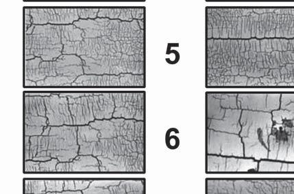
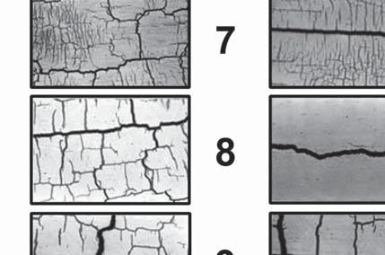
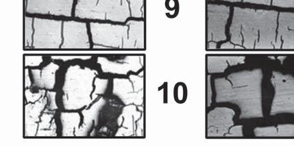
28 Tooling for Die Casting 5.2 Thermal Balancing To achieve maximum product quality, the dies are required to run at a precise, specified temperature. This temperature will vary with such factors as the size of the casting, number of die cavities, alloy being cast and machine cycle time. The alloy is injected into the die at this exact temperature at high speeds and then rapidly cooled for ejection. This extremely fast and repeated cooling requires careful engineering of a complex network of internal die temperature lines. Infrared imaging and thermocouples placed in the die can help measure and maintain correct die temperatures. Proper thermal balancing through the strategic placement of these lines reduces die casting cycle time, improves casting quality, and lengthens the life of the die. Different areas of the die can be heated or cooled to different temperatures, i.e., different cover half and ejector half temperatures can be used to aid control of part density or surface finish. 5.3 Oil Heating Lines In some cases differential heating of various areas of the die to produce specific casting design features will be achieved by the use of hot oil lines in the die. Hot oil systems heat a special oil to a given elevated temperature and pipe it through the die in the same manner as water cooling lines. Both water cooling and hot oil heating lines may be used. 5.4 Alternate Surface Textures Using photoengraving techniques in making the die cavities, a wide range of patterns, grainings and textures can be selected for permanent die casting into the surface of a part. The die caster can exhibit actual samples of the common die cast textures possible. (For illustrations of sample textures, see the Surface Treatment chapter of Product Design for Die Castings.) 5.5 Extended Die Life While optimum die life begins with high quality tool steel, several patented processes are available which can be used to extend the life of a die casting die. These processes involve shot peening techniques, submersion in special baths, and chemical treatments of the die. The die caster can discuss the projected effectiveness of such steps to reduce premature die wear in the case of specific part design. A typical failure mode of dies is heat checking or thermal fatigue cracking Heat Checking. Die Casting tools show small cracks (network) as well as bigger (leading) cracks after some time in use, due to thermal fatigue. Both are important to tool life. The scale in figure 2-13 is designed to give you a combined grading using both network and leading crack values. Compare the scales with your tool. Give the tool a grading from both scales. Add the two gradings. These two combined readings give you the degree of heat checking NADCA Product Specification Standards for Die Castings / 2015


29 Tooling for Die Casting 2 NADCA Product Specification Standards for Die Castings /
30 Tooling for Die Casting Determine at what point the die will no longer be useful. For critical surfaces, such as those to be polished or chrome plated, you might stop using the die at a combined rating of six. For other surfaces, especially those not seen by users of the finished product, the die might be used until the rating is judged to be greater than 14. As the rating goes up, there is not only an aesthetic loss but an economic loss in the production of the parts. The scale also provides a concrete basis of comparison between different tools and number of shots. 6 Secondary Machining Preplanning While most die castings are produced to near-net-shape, and many to net-shape, the close tolerances possible with die casting and the repeatability of the process suits die cast parts to economical high-precision secondary machining operations. A die casting can be designed to accurately adapt to machining fixtures by casting in locator holes or casting a flush locating datum surface. Die castings can be drilled, tapped, reamed, punched, or have nearly any type of machining operation performed on them. Machining operations, including gaging and any other secondary operations that may be required, can be performed by the die caster. Properly designing the part and the die for optimum quality and economy in secondary machining will have an important impact on reducing final part costs. Detailed discussions should be held with die caster engineering personnel to establish such machining parameters as the precise location, extent, and depth of the machining required; the surface finish required; and any other specification necessary to result in a quality component. Decisions on special machining equipment ownership, maintenance and replacement must also be discussed. Such matters are outlined in the Commercial Practices section of this manual (page 8-1). 7 Gaging Considerations What gages will be used in casting production and in secondary machining, and what they will check, are important elements of the die casting program. Gages may be used to check the casting in its as-cast state and again after machining. The gage may be an attribute gauge, which is basically a go or no-go check and results in either a good or bad part. A variable gage may also be employed which, used with a computer, can document variables, collect data, and record Cpk s. More than one gage may be needed to check a casting: one to check it in its as-cast condition and another to check the casting in a fully machined condition. There may be a need for plug and thread gages as well as finished gages or standards for painted surfaces. The gaging should be considered by the customer as part of the tooling package. Gaging requirements should be resolved early by the quality assurance managers of both the customer and the die caster, so no questions remain on meeting the part print requirements NADCA Product Specification Standards for Die Castings / 2015
31 Tooling for Die Casting 8 Inherited Tooling In some instances a customer may transfer a die casting die from one die caster to another. This generally will raise some operational questions for the receiving die caster of which the customer should be aware. The die may need to be put into a different type of die casting machine. This may require some modifications to the die s ejector system as well as to the shot sleeve, i.e. the entry for molten metal. The die s gate and runner system may also need to be modified to suit the new machine conditions. It may be necessary for any residual oil in the hydraulic system of the die to be sent out for sampling to assure that it does not contain any contaminants. The die must be evaluated by the customer and the die caster s tool room superintendent to assure that there are no visual problems with the die. They should also determine whether the die arrived with any required limit switches and hydraulic cylinders. Upon this review an adaptation cost can be established and agreed upon before the receiving die caster has invested a large amount of time and expense in preproduction work. Checklist T-2-1, at the end of this section, will aid in addressing questions regarding transferred or inherited tooling. Die or tooling ownership and replacement is often a point of discussion. Information regarding this topic can be found in Section Engineering Consultation The customer company, in the person of its engineering and quality assurance personnel, will usually be requested to meet with the custom die caster s engineering and quality assurance personnel as early as possible to discuss the design and function of the part design proposed for die casting. They will discuss the design s function, fit and precise assembly with other components. The die casting process uniquely lends itself to parts consolidation, decreasing the number of components in a product assembly. Early involvement with the die caster is essential in avoiding expensive corrective steps in later die construction. It can often simplify product assembly and significantly reduce total product costs. For example, an attached hinge bracket could be die cast as an integral part of the casting. A slight design modification could assure clearance for a close assembly. The die caster may be able to cast an integral bearing in the part that the customer was planning to press in. Or the die caster may be able to perform a complete or partial assembly operation more economically, such as installing a gasket after painting the casting, and shipping the part ready for assembly. Many die casters have in-house capabilities for operations such as pressure testing, impregnating, machining, surface finishing and subassembly. The experienced die caster should be regarded as a invaluable source of expertise in the die casting production and assembly process. Depending on part configuration, very small high-volume zinc parts, weighing fractions of an ounce, may be recommended for production on special hot-chamber zinc die casting machines. Such parts, usually called miniature or microminiature die castings, can be cast flash-free, with zero draft, to very close net-shape tolerances. NADCA Product Specification Standards for Die Castings /
32 Tooling for Die Casting 10 Database Guidelines When databases are utilized, quotations for castings are often based on the assumption that any CAD databases provided to build tooling and produce parts are complete, usable and are without need of updating. Databases may be deemed incomplete and unusable if: Note: The database file format may not be compatible with existing capabilities and may require a translator. STL files are usually only used for creation of prototype parts. Any necessary database manipulation that is caused by incompleteness as described above could add cost and extended lead-time to tooling. If databases are designed only to nominal dimensions, tool life and casting tolerances may be adversely impacted. If solid model databases are used for tool construction, they should be accompanied by a limited dimension part print (either paper or database) that contains all tolerancing information and information pertaining to any secondary machining that is to be performed to the part. The revision control for databases should be as agreed upon between the die caster and customer. 11 New Die/Inherited Die Specifications Checklist T-2-1, which follows, will aid in discussions between the customer and the die caster regarding the important considerations in the design of a new die casting die or in the production of parts from inherited tooling. 12 Die Life Die casters are frequently asked the question, How many shots will I get from the die before it needs to be replaced? or How many shots will you guarantee the die for? A better question might be, What can we do to maximize die life and to minimize replacement costs? Aluminum and Copper die casting dies wear out due to the aggressive nature and high melting temperatures of the materials being die cast. Die life is a consideration of part design, part function, internal part requirements and part cosmetics. In general, cosmetic areas of the part do not last as long as functional areas. The following is a suggested approach to be used by the customer and die caster at the time of part design. The intent is to define critical areas of the die casting before the start of tool design. This allows areas to be inserted to maximize die life and minimize the replacement costs. First, is to develop a rating scale by which this information can be used to relate part considerations to estimated tool life. A guideline (T-2-2) has been developed and includes; a Die Life Checklist, sample part, example of tool steel inserting and identification matrix starting on page NADCA Product Specification Standards for Die Castings / 2015
33 Tooling for Die Casting 13 Checklist for Die Casting Die Specifications (To be used in consultation with your Die Caster) Part 1 New Die Casting Dies: Items to be Addressed In the case of new die casting dies, all of the items in Part 1, below, should be reviewed. Note, in the case of tooling to be transferred to, or inherited by a die caster, the items asterisked (*) in Part 1 should be addressed, plus the items noted in Part 2 on the next page. Type of New Die Cavity Steel* Cavity Steel Heat Treat* Cored Holes* Die Operation for Part Features* Estimated Part Volume Casting Alloy* Casting Weight As-cast Part Finish* Class of Die Cast-In Date Insert* Cast-In Part Number* Other Prototype Die Casting Die Production Die Casting Die H13 Premium Grade H13 Superior Grade H13 Other Tool Steel: NADCA No. 229 Certification Required: Yes No Grade Hardness Required: Toughness Required: ft.-lbs NADCA No. 229 Certification Required: Yes No All Holes Cored Cored Holes As Noted On Print No Cored Holes Mechanical Movement Hydraulic Movement Features To Be Achieved By Secondary Operations Monthly: Annual: Expected Product Life: Aluminum Copper Magnesium Zinc ZA Alloy Estimated Casting Weight: Mechanical Grade (Functional Finish) (Ref. 125 Ra) Painting Grade (Ref 63 Ra) Highest Quality (Cosmetic Finish) For Plating, Etc. (Ref. 32 Ra) *Die wear can affect surface finish over the life of the die. Unit Die Conventional Die Single Cavity Multiple Cavity Multiple Cavity - Family Die In Die Cavity Other Requirements: Not Required In Die Cavity Other Requirements: Not Required Class Write in any other special requirements (ie. tolerances, leak testing, x-rays): NADCA T Checklist This two-part specification checklist is intended for use in consultation with your die caster prior to estimation of new die design and construction, or prior to die casting production using inherited tooling. It should be used in combination with checklists C-8-1 and C-8-2 in Commercial Practices, Section 8. 2 NADCA Product Specification Standards for Die Castings /
34 Tooling for Die Casting NADCA T Checklist This two-part specification checklist is intended for use in consultation with your die caster prior to estimation of new die design and construction, or prior to die casting production using inherited tooling. It should be used in combination with checklists C-8-1 and C-8-2 in Commercial Practices, Section 8. Part 2 New Die Casting Dies: Items to be Addressed (Continued) Cast-In Logo, Lettering* Die Layout First-Piece Approval Gages* Trim Die Machining Fixtures Special Items In Die Cavity Other Include: Customer Logo Cavity No. Supplier Logo Revision No. Recycling Logo Part Number Customer to Approve Layout Approval by Die Caster Customer Approval Before Production Run Required Run on Die Caster Approval PPAP Customer to Supply Special Gages Die Caster to Supply Special Gages Mechanical Movement Hydraulic Movement Features To Be Achieved By Secondary Operations No Secondary machining required Machining reguired, no special fixtures Special machining fixtures required, customer to supply Special machining fixtures required, die caster to supply Special Items to be included in the tooling package: Part 3 Inherited Die Casting Dies: Additional Items to be Addressed In the case of inherited tooling, not the asterisked items (*) in Part 1, plus the items below. Note that with transferred, or inherited, tooling for die casting production the existing die casting die, the trim die, and, if required, the secondary machining fixtures, must be available for review and evaluation to determine whether the dies and fixtures are capable of producing to specifications and the extent of maintenance and/or rework required before the onset of production. This would include any adaptations of the die caster s equipment to accommodate production using the inherited dies. Final production estimates will be based on this review. Inherited Die Inherited Trim Die Inherited Machining Fixtures Actual Casting Weight Size of Die Weight of Die Availability of Die Design Die Casting Die Available for Evaluation Die to be Available for Evaluation (date): Trim Die Not Required Trim Die Available for Evaluation Trim Die to be Available for Evaluation (date): Special Machining Fixtures Not Required Machining Fixtures Available for Evaluation Machining Fixtures to be Available for Evaluation (date): Weight of Actual Casting: Size of Casting Die (for equipment limitations): Weight of Casting Die (for crane limitations): Yes No 2-18 NADCA Product Specification Standards for Die Castings / 2015
35 Tooling for Die Casting 14 Guidelines to Increase Die Life Die Life Checklist NADCA Before the start of tooling Class A B C D E Class Part Consideration Critical to Function & Cosmetic Cosmetic, No Function Critical to Function Not Critical but Functional No Function Estimated Die Life/Shots Less than 10,000 10,000 to 25,000 25,000 to 50,000 50,000 to 100,000 T Guideline 2 5 More than 100,000 Using the above will develop and itemize the areas of concern of a sample part. NADCA Product Specification Standards for Die Castings /
36 Tooling for Die Casting Using the sample, the next step is to develop an inserting plan for the tool steel construction. Last is to develop the matrix for communication of tool steel replacement needs and to develop history on each insert. (The information shown in this example represents only what can be done. The actual information to be included should be determined by the customer and the die caster). Two examples of this type of matrix are shown, at the start of a new project and the other as it may appear after the first year of production NADCA Product Specification Standards for Die Castings / 2015
37 Tooling for Die Casting 2 As mentioned earlier this is just a suggested approach to improving die life and reducing replacement costs. Die casting dies do wear out. It is an advantage to both the customer and the die casters benefit to layout a plan at the start of the project. This allows inserts to be replaced before any actual failure thus preventing any possible loss of production. The examples shown are only one of many possible methods to achieve this. If the customer and die caster choose to use this type of approach, it should be on a part by part basis. The information in the matrix should be relevant to the actual tool construction and the actual annual usage. NADCA Product Specification Standards for Die Castings /
38 Tooling for Die Casting 2-22 NADCA Product Specification Standards for Die Castings / 2015
39 Alloy Data Section Contents NADCA No. Format Page Frequently Asked Questions (FAQ) 3-2 SECTION 3 1 Die Casting Alloy Cross Reference Designations Aluminum Alloys 3-4 Selecting Aluminum Alloys 3-4 Aluminum Alloy Chemical Composition A Standard 3-5 Aluminum Alloy Properties A Standard 3-6 Aluminum Alloy Characteristics A Guidelines Aluminum Metal Matrix Composites Selecting Aluminum Composites 3-12 Aluminum Composites Chemical Composition A Standard 3-13 Aluminum Composites Properties A Standard 3-14 Aluminum Composites Characteristics A Guidelines Copper Alloys 3-16 Selecting Copper Alloys 3-16 Copper Alloy Chemical Composition A Standard 3-17 Copper Alloy Properties A Standard 3-18 Copper Alloy Characteristics A Guidelines Magnesium Alloys 3-20 Selecting Magnesium Alloys 3-20 Magnesium Alloy Chemical Composition A Standard 3-21 Magnesium Alloy Properties A Standard 3-22 Magnesium Alloy Characteristics A Guidelines Zinc and ZA Alloys 3-26 Selecting Zinc and ZA Alloys 3-26 Zinc and ZA Alloy Chemical Composition A Standard 3-27 Zinc and ZA Alloy Properties A Standard 3-28 Zinc and ZA Alloy Characteristics A Guidelines 3-29 High Fluidity (HF) Properties and Composition Selecting An Alloy Family Quick Guide to Alloy Family Selection Elevated Temperature Properties Property Comparison Cross Reference: Alloy Designation and Composition NADCA Product Specification Standards for Die Castings /
40 Alloy Data The cross reference designations shown are for alloy References apply to the metal in the die cast condition and should not be confused for metal ingot. A in a column indicates that the tered by the given source. Frequently Asked Questions (FAQ) 1) Is there a cross reference available for different alloy designations? See pages 3-2, 3-3 all charts and pages 3-42 through ) What type of material best fits my application? See page 3-33, Quick Guide to Alloy Family Selection. 3) How do die cast properties compare to sand cast properties? See pages 3-38 through 3-41, Property Comparison. 4) Where can I find general material properties for Aluminum Alloys? See pages 3-4 through ) How can I determine if certain die casting alloys would be a better choice for thermal conductivity? See row Thermal Conductivity in tables found on pages 3-6, 3-14, 3-18, 3-22, 3-28, and Die Casting Alloy Cross Reference Designations Table of Symbols UNS ANSI Unified Numbering System American National Standards Institute ASTM American Society for Testing and Materials AA SAE FED Aluminum Association Society of Automotive Engineers Federal Specifications Aluminum Alloy Specifications Commercial UNS ANSI AA ASTM B85 Former SAE J452 Federal QQ-A-591 b DIN g 1725 JIS H A SG100B b A360 a A13600 A360.0 SG100A 309 b 233 ADC3 380 c A SC84B 308 b A380 a c A13800 A380.0 SC84A 306 B 226A e ADC10 CD 383 A SC102A 383 b 226A e ADC12 CD 384 A SC114A 303 b ADC12 CD A384 a A384.0 b ADC12 CD B390 A23900 B390.0 SC174B b 13 A S12B b A13 a A14130 A413.0 S12A 305 b 231D f ADC1 c 43 A34430 C443.0 S5C 304 b 218 A G8A b 341 a b c d e f g Note: MIL JIS Military Specifications Japanese Industrial Standard DIN German Industrial Standard 3-2 NADCA Product Specification Standards for Die Castings / 2015
41 Alloy Data Aluminum Metal Matrix Composite Alloy Specifications Copper Alloy Specifications Rio Tinto Alcan CANADA UNS AA Commercial UNS ASTM B176 SAE J461/ F3D.10S-F 380/SiC/10p 857 C85700 F3D.20S-F 380/SiC/20p 858 C85800 Z30A J462 F3N.10S-F 360/SiC/10p 865 C86500 F3N.20S-F 360/SiC/20p 878 C87800 ZS144A J C C Magnesium Alloy Specifications Commercial UNS ASTM B93 & B94 Former SAE J465B Federal a DIN 1729 NADCA Product Specification Standards for Die Castings / 2015 JIS H 2222 & H 5303 AZ91B M11912 AZ91B 501A QQ-M MDI1B AZ91D M11916 AZ91D MDI1D AZ81 AM60A M10600 AM60A MDI2A AM60B M10602 AM60B MDI2B AM50 AE42 AS41A M10410 AS41A MDI3A AS41B M10412 AS41B AM20 a This Federal Specification has been canceled and is shown for historic reference only. Note: Zinc and ZA Alloy Specifications Commercial UNS ASTM B86 Former SAE J469 Federal a QQ-Z-363a DIN JIS H Z35541 AC43A 921 AC43A Z33520 AG40A 903 AG40A 1743 ZDC-2 5 Z AC41A 925 AC41A 1743 ZDC-1 7 Z33523 AG40B AG40B ZA-8 Z35636 ZA-12 Z35631 ZA-27 Z35841 a This Federal Specification has been canceled and is shown for historic reference only. Note: Table of Symbols UNS ANSI Unified Numbering System American National Standards Institute ASTM American Society for Testing and Materials AA SAE FED MIL JIS DIN Aluminum Association Society of Automotive Engineers Federal Specifications Military Specifications Japanese Industrial Standard German Industrial Standard 3-3
42 Alloy Data 2 Aluminum Alloys Selecting Aluminum Alloys Aluminum (Al) die casting alloys have a specific gravity of approximately 2.7 g/cc, placing them among the lightweight structural metals. The majority of die castings produced worldwide are made from aluminum alloys. Six major elements constitute the die cast aluminum alloy system: silicon, copper, magnesium, iron, manganese, and zinc. Each element affects the alloy both independently and interactively. This aluminum alloy subsection presents guideline tables for chemical composition, typical properties, and die casting, machining and finishing characteristics for 11 aluminum die casting alloys. This data can be used in combination with design engineering tolerancing guidelines for aluminum die casting and can be compared with the guidelines for other alloys in this section and in the design engineering section. Alloy A380 (ANSI/AA A380.0) is by far the most widely cast of the aluminum die casting alloys, offering the best combination of material properties and ease of production. It may be specified for most product applications. Some of the uses of this alloy include electronic and communications equipment, automotive components, engine brackets, transmission and gear cases, appliances, lawn mower housings, furniture components, hand and power tools. Alloy 383 (ANSI/AA 383.0) and alloy 384 (ANSI/AA 384.0) are alternatives to A380 for intricate components requiring improved die filling characteristics. Alloy 383 offers improved resistance to hot cracking (strength at elevated temperatures). Alloy A360 (ANSI/AA A360.0) offers higher corrosion resistance, superior strength at elevated temperatures, and somewhat better ductility, but is more difficult to cast. While not in wide use and difficult to cast, alloy 43 (ANSI/AA C443.0) offers the highest ductility in the aluminum family. It is moderate in corrosion resistance and often can be used in marine grade applications. Alloy A13 (ANSI/AA A413.0) offers excellent pressure tightness, making it a good choice for hydraulic cylinders and pressure vessels. Its casting characteristics make it useful for intricate components. Alloy B390 (ANSI/AA B390.0) was developed for automotive engine blocks. Its resistance to wear is excellent but, its ductility is low. It is used for die cast valve bodies and sleeve-less piston housings. Alloy 218 (ANSI/AA 518.0) provides the best combination of strength, ductility, corrosion resistance and finishing qualities, but it is more difficult to die cast. * Different sets of properties can be achieved with alternate processes (such as high vacuum, squeeze, and semi-solid casting) and alternate alloys (such as A356, Aural 2 or 356, and Silafont 36). Information on these processes and alloys can be found in the Product Specification Standards for Die castings produced by Semi-Solid and Squeeze Cast Processes (NADCA Publication #403) and the High Integrity Die Castings book (NADCA Publication #404). Machining Characteristics Machining characteristics vary somewhat among the commercially available aluminum die casting alloys, but the entire group is superior to iron, steel and titanium. The rapid solidification rate associated with the die casting process makes die casting alloys somewhat superior to wrought and gravity cast alloys of similar chemical composition. Alloy A380 has better than average machining characteristics. Alloy 218, with magnesium the major alloying element, exhibits among the best machinability. Alloy 390, with the highest silicon content and free silicon constituent, exhibits the lowest. Surface Treatment Systems Surface treatment systems are applied to aluminum die castings to provide a decorative finish, to form a protective barrier against environmental exposure, and to improve resistance to wear. Decorative finishes can be applied to aluminum die castings through painting, powder coat finishing, polishing, epoxy finishing, and electro-chemical processing. Aluminum can be plated by applying an initial immersion zinc coating, followed by conventional copper-nickel-chromium plating procedure 3-4 NADCA Product Specification Standards for Die Castings / 2015
43 Alloy Data NADCA A STANDARD similar to that used for plating zinc metal/alloys. Protection against environmental corrosion for aluminum die castings is achieved through painting, anodizing, chromating, and iridite coatings. Improved wear resistance can be achieved with aluminum die castings by hard anodizing. Where a part design does not allow the production of a pressure-tight die casting through control of porosity by gate and overflow die design, the location of ejector pins, and the reconfiguration of hardto-cast features, impregnation of aluminum die castings can be used. Systems employing anaerobics and methacrylates are employed to produce sealed, pressure-tight castings with smooth surfaces. A detailed discussion of finishing methods for aluminum die castings can be found in Table A-3-1 Chemical Composition: Al Alloys 3 Aluminum Die Casting Alloys ae Commercial: ANSI/AA A360 A b A380 b A b B390* B A13 A C Nominal Comp: Mg 0.5 Si 9.0 Mg 0.5 Si 9.5 Cu 3.5 Si 8.5 Cu 3.5 Si 8.5 Cu 2.5 Si 10.5 Cu 3.8 Si 11.0 Cu 4.5 Si 17.0 Si 12.0 Si 12.0 Si 5.0 Mg 8.0 Detailed Composition Silicon Si Iron Fe Copper Cu Magnesium Mg Manganese Mn Nickel Ni Zinc Zn Tin Sn Titanium Ti Others Each Total Others c Aluminum Al f 0.30 f Balance Balance Balance Balance Balance Balance Balance Balance Balance Balance Balance a b c D E f * NADCA Product Specification Standards for Die Castings /
44 Alloy Data Table A-3-2 Typical Material Properties: Al Alloys Commercial: ANSI/AA Aluminum Die Casting Alloys A360 A360.0 Mechanical Properties Ultimate Tensile Strength ksi (MPa) (303) (317) Yield Strength a ksi 25 (MPa) (172) Elongation % in 2in. (51mm) 24 (165) (317) 23 (159) A380 EF A (324) 23 (159) 383 E (310) 22 (152) (331) 24 (165) B390* B (317) 36 (248) (296) 21 (145) A13 A (290) 19 (131) 3-6 NADCA Product Specification Standards for Die Castings / C (228) < Hardness b BHN Shear Strength ksi (MPa) 28 (193) Impact Strength ft-lb (J) Fatigue Strength c ksi (MPa) NADCA A STANDARD 20 (138) Young s Modulus psi x (GPa) (71) Physical Properties Density lb/in 3 (g/cm 3 ) Melting Range F ( C) Specific Heat BTU/lb F (J/kg C) (2.63) ( ) (963) 26 (179) 18 (124) 10.3 (71) (2.63) ( ) (963) Coefficient of Thermal Expansion in/in F ( m/m K) 11.6 (21.0) 11.6 (21.0) Thermal Conductivity BTU/ft hr F 65.3 (W/m K) (113) 65.3 (113) 28 (193) 3 (4) 20 (138) 10.3 (71) (2.74) ( ) (963) 12.2 (22.0) 55.6 (96.2) 27 (186) 20 (138) 10.3 (71) (2.71) ( ) (963) 12.1 (21.8) 55.6 (96.2) 3 d (4) 21 (145) 10.3 (71) (2.74) ( ) (963) 11.7 (21.1) 55.6 (96.2) 29 (200) 25 (172) 25 (172) 14 (97) 20 (138) (2.82) ( ) 20 (138) 11.8 (81) 11.6 (21.0) 55.6 (96.2) (2.71) ( ) 10.0 (18.0) 19 (131) 10.3 (71) (2.66) ( ) (963) 11.3 (20.4) 19 (131) (2.66) ( ) (963) 11.9 (21.6) 19 (131) 17 (117) 10.3 (71) (2.69) ( ) (963) 12.2 (22.0) Electrical Conductivity % IACS (134) 70.1 (121) 70.1 (121) 82.2 (142) (310) 28 (193) 29 (200) 7 (9) 20 (138) (2.57) ( ) 13.4 (24.1) 55.6 (96.2) Poisson s Ratio a b c d E F
45 Alloy Data NADCA A GUIDELINES Die casting alloy selection requires evaluation not only of physical and mechanical properties, and chemical composition, but also of inherent alloy characteristics and their effect on die casting production as well as possible machining and final surface finishing. This table includes selected die casting and other special characteristics which are usually considered in selecting an aluminum alloy for a specific application. The characteristics are rated from (1) to (5), (1) being the most desirable and (5) being the least. In applying these ratings, it should be noted that all the alloys have sufficiently good characteristics to be accepted by users and producers of die castings. A rating of (5) in one or more categories would not rule out an alloy if other attributes are particularly favorable, but ratings of (5) may present manufacturing difficulties. The benefits of consulting a custom die caster experienced in casting the aluminum alloy being considered are clear. Table A-3-3 Die Casting And Other Characteristics: Al Alloys Commercial: ANSI/AA Aluminum Die Casting Alloys A360 A A380 A * B A13 A C443.0 Resistance to Hot Cracking a Pressure Tightness Die-Filling Capacity b Anti-Soldering to the Die c Corrosion Resistance d Machining Ease & Quality e Polishing Ease & Quality f Electroplating Ease & Quality g Anodizing (Appearance) h Chemical Oxide Protective Coating i Strength at Elevated Temp. j a b c d e f g h i Note: Additional A380 Alloy Tensile Data Alloys Tensile ksi (MPa) Yield ksi (MPa) Elong % A380 at 0.09% Mg 45.5 (243) 23.8 (135) 2.6 A380 with 0.26% Mg 47.0 (201) 26.6 (183) 2.8 A380 with 0.33% Mg % Sr* 45.7 (177) 28.5 (196) 2.4 NADCA Product Specification Standards for Die Castings /
46 Alloy Data Table 1: Composition of Three Experimental Alloys as Compared to A380. Composition (%) Si Cu Mg Fe Mn Zn Ni Ti Sr A <0.1 <1.3 <0.5 <3 <0.5 A380* <0.1 <0.2 <0.005 AMC AMC 1045Sr <0.3 <0.05 < Table 2: Tensile properties of separately die cast specimens of the experimental alloys compared to separately die cast specimens of alloy A380. Alloy A380 A380* AMC 380* AMC 1045Sr Gage length (inch) UTS YS e Modulus of Elasticity Value (Ksi) Vs A380 (%) Value (Ksi) Vs A380 (%) Value (%) Vs A380 (%) 45.6 ± ± ± ± ± ± ± ± ± ± ± ± ± ± ± ± ± ± ± ± ± ± Value (10 3 Ksi) 11.0 ± ± ± ± ± ±0.2 Vs A380 (%) ± ± ± ± Table 3: Tensile properties measured on specimens that were cut from die cast components. Alloy A380 AMC 380 AMC 1045Sr AMC 1045 UTS YS e Modulus of Elasticity Value (Ksi) Vs A380 (%) Value (Ksi) Vs A380 (%) Value (%) Vs A380 (%) Value (10 3 Ksi) Vs A380 (%) 39.4 ± ± ± ± ± ± ± ± ± ± ± ± ± ± ± ± NADCA Product Specification Standards for Die Castings / 2015
47 Alloy Data Table 4: Elevated temperature and room temperature tensile properties of the experimental alloys and commercial A380 alloy. Tests were conducted at temperature on separately die cast tensile specimens. Alloy Test Condition TS (Ksi) YS (Ksi) e (%) Modules of Elasticity (X10 3 Ksi) 25 C (as-cast) 45.6± ± ± ± h 42.0± ± ± ±0.5 A C 500 h 42.7± ± ± ± h 43.4± ± ± ± h 30.1± ± ± ± C 500 h 25.0± ± ± ± h 24.2± ± ± ± C (as-cast) 46.3± ± ± ± h 41.1± ± ± ±0.7 A380* 100 C 200 C 500 h 41.5± ± ± ± h ± ± ± h 30.1± ± ± ± h 25.6± ± ± ± h 24.4± ± ± ± C (as-cast) 49.9± ± ± ± h 46.6± ± ± ±0.3 AMC C 200 C 500 h 46.5± ± ± ± h 46.9± ± ± ± h 36.5± ± ± ± h 31.8± ± ± ± h 29.3± ± ± ± C (as-cast) 53.4± ± ± ± h 50.1± ± ± ±0.2 AMC1045Sr 100 C 200 C 500 h 50.2± ± ± ± h 50.4± ± ± ± h 45.0± ± ± ± h 33.5± ± ± ± h 30.8± ± ± ±0.4 NADCA Product Specification Standards for Die Castings /
48 Alloy Data Table 5: Tensile properties of the experimental alloys at temperature and after exposure to temperature. Specimens were separately die cast. Alloy Test Condition TS (Ksi) YS (Ksi) e (%) Modules of Elasticity (X10 3 Ksi) 25 C (as-cast) 45.6± ± ± ±1.1 A380 Cooled to 25 C Tested at 200 C 0.5 h 45.0± ± ± ± h 38.4± ± ± ± h 38.5± ± ± ± h 30.1± ± ± ± h 25.0± ± ± ± h 24.2± ± ± ± C (as-cast) 46.3± ± ± ±1.4 A380* Cooled to 25 C Tested at 200 C 0.5 h 41.4± ± ± ± h 39.0± ± ± ± h 37.3± ± ± ± h 30.1± ± ± ± h 25.6± ± ± ± h 24.4± ± ± ± C (as-cast) 49.9± ± ± ±1.2 AMC380 Cooled to 25 C Tested at 200 C 0.5 h 48.0± ± ± ± h 43.9± ± ± ± h 45.1± ± ± ± h 36.5± ± ± ± h 31.8± ± ± ± h 29.3± ± ± ± C (as-cast) 53.4± ± ± ±0.8 AMC1045Sr Cooled to 25 C Tested at 200 C 0.5 h 49.5± ± ± ± h 45.1± ± ± ± h 44.1± ± ± ± h 45.0± ± ± ± h 33.5± ± ± ± h 30.8± ± ± ± NADCA Product Specification Standards for Die Castings / 2015
49 Alloy Data Table 6: Fatigue strength of experimental alloys as compare to A380. Specimens were separately die cast and tested using the R.R Moore rotating bending fatigue test. Alloy A380 A380* AMC380 AMC1045Sr Cycles 1x10 8 5x10 8 1x10 8 5x10 8 1x10 8 5x10 8 1x10 8 5x10 8 Maximum stress (ksi) Change vs. A % -9.22% +3.34% +1.39% +8.33% +8.98% Table 7: Composition of suggested alloys and company specific alloys as compared to A380 3 Composition (%) Si Cu Mg Fe Mn Zn Ni Ti Sr Other A High Mg A F B Gibbsalloy MN Table 8: Tensile properties of separately die cast specimens of the suggested and company specific alloys compared to separately die cast specimens of alloy A380. Alloy UTS (ksi) YS (ksi) e (%) A Hi Mg Hi Mg 380-T F B B360-T Gibbsalloy MN Gibbsalloy MN-T NADCA Product Specification Standards for Die Castings /
50 Alloy Data 3 Aluminum Metal Matrix Composites Selecting Aluminum Composites Aluminum metal matrix composites (MMC) are aluminum-based alloys reinforced with up to 20% silicon carbide (SiC) particles, which are now being used for high-performance die cast components. The mechanical properties of ASTM test specimens made from these materials typically exceed those of most aluminum, magnesium, zinc and bronze components produced by die casting, and match or approach many of the characteristics of iron castings and steel at lighter weight. The expected properties of MMC parts are higher stiffness and thermal conductivity, improved wear resistance, lower coefficient of thermal expansion, and higher tensile and fatigue strengths at elevated temperature, with densities within 5% of aluminum die casting alloys. These composites can also yield castings with reduced porosity. Preliminary data also indicates that less vibrational noise is generated by parts made from these composites, under certain conditions, than by identical parts made from unreinforced aluminum. Duralcan F3D.10%v/v and 20%v/v aluminum metal matrix composites reinforced with SiC ceramic powder are general purpose die casting alloys. Duralcan F3N.10%v/v and 20%v/v aluminum metal matrix composites reinforced with SiC ceramic powder contain virtually no copper or nickel and are designed for use in corrosion sensitive applications. All of these composites are heat treatable. Machining Characteristics Al-MMCs are significantly more abrasive to cutting tools than all other aluminum die cast and gravity cast alloys, except for hypereutectic Al-Si alloys (those containing primary Si phases). Coarse grades of polycrystalline diamond (PCD) tools are recommended for anything more than prototype quantities of machining. With the proper tooling, Al-MMC can be readily turned, milled, or drilled. However, cutting speeds are lower and feed rates are higher than for unreinforced alloys. General machining guidelines are described in Volume 1 of the SME Tool & Manufacturing Engineers Handbook. Surface Treatment Systems Surface treatments are generally applied to aluminum MMC to provide a protective barrier to environmental exposure, to provide decorative finish, or to reduce the abrasiveness of the MMC to a counterface material. Because of the inherently high wear resistance of the Al-MMCs, surface treatments on these materials are generally not used to improve their wear resistance. Decorative finishes can be applied by painting, powder coat finishing, epoxy finishing and plating, using procedures similar to those used for conventional aluminum alloys. Although conventional and hard-coat anodized finishes can be applied to Al-MMC die castings, the results are not as cosmetically appealing as for conventional aluminum. The presence of the SiC particles results in a darker, more mottled appearance. This problem can be minimized, although not entirely eliminated, by using the darker, more intensely colored dyes to color the anodic coatings. Another problem often noted is that the presence of the ceramic particles produces a rougher surface, particularly after chemical etching. This, in turn, leads to a less lustrous anodic coating than usually seen with unreinforced aluminum. Recommended procedures for painting, plating and anodizing Duralcan MMCs can be obtained through Rio Tinto Alcan, 2040 Chemin de la Reserve, Chicoutimi (Quebec) G7H 5B3, Canada. This aluminum composite subsection presents guideline tables for chemical composition, typical properties, and die casting and other characteristics for the two families of aluminum matrix composite alloys for die casting. Design engineering tolerancing guidelines have yet to be developed. Rio Tinto Alcan - Dubuc Works, produces Duralcan metal matrix composites for die casting using a patented process and proprietary technology, mixing ceramic powder into molten aluminum. Further technical and application information can be obtained from Rio Tinto Alcan, 2040 Chemin de la Reserve, Chicoutimi (Quebec) G7H 5B3, Canada NADCA Product Specification Standards for Die Castings / 2015
51 Alloy Data NADCA A STANDARD Table A-3-4 Chemical Composition: Al-MMC Alloys Duralcan Aluminum Metal Matrix Composite Alloys B Commercial: F3D.10S-F F3D.20S-F F3N.10S-F F3N.20S-F Detailed Composition SiC Particulate Volume Percent 10% 20% 10% 20% Silicon Si Iron Fe Copper Cu max max. Magnesium Mg Manganese Mn Nickel Ni Titanium Ti 0.05 max max max max. Zinc Zn 0.05 max max max max. Total Others A Aluminum Al 0.10 Total 0.03 max Total 0.03 max Total 0.03 max Total 0.03 max. Balance Balance Balance Balance 3 A B NADCA Product Specification Standards for Die Castings /
52 NADCA A STANDARD Alloy Data Table A-3-5 Typical Material Properties: Al-MMC Alloys Duralcan Aluminum Metal Matrix Composite Alloys Commercial: F30D.10S-F F30D.20S-F F30N.10S-F F30N.20S-F Mechanical Properties Ultimate Tensile Strength a ksi (MPa) 50 (345) 51 (352) 45 (310) 44 (303) Yield Strength a ksi (MPa) 35 (241) 44 (303) 32 (221) 36 (248) Elongation a % in 2in. (51mm) Rockwell Hardness a HRB Impact Energy b Charpy impact ASTM E-23 (J) Fatigue Strength C ksi (MPa) Elastic Modulus a psi x 10 6 (GPa) Physical Properties Density lb/in 3 (g/cm 3 ) Melting Range F ( C) Specific Heat BTU/lb 77 F (J/kg 22 C) 22 (152) 10.3 (71) (2.76) ( ) (841.5) 22 (152) 10.3 (71) (2.82) ( ) (829.0) Average Coefficient of Thermal Expansion in/in F ( m/m K) 10.7 (19.3) 9.4 (16.9) Thermal Conductivity BTU/ft hr 72 F (W/m 22 C) 71.6 (123.9) 83.2 (144.0) 20 (140) (2.65) ( ) (870.9) 11.9 (21.4) 93.0 (161.0) 15.7 (108.2) (2.71) ( ) (808.1) 9.2 (16.6) 97.1 (168.1) Electrical Conductivity % 22 C Poisson s Ratio a b c 3-14 NADCA Product Specification Standards for Die Castings / 2015
53 Alloy Data NADCA A GUIDELINES Die casting alloy selection requires evaluation not only of physical and mechanical properties, and chemical composition, but also of inherent alloy characteristics and their effect on die casting production as well as possible machining and final surface finishing. This table includes selected die casting and other special characteristics which are usually considered in selecting an aluminum matrix alloy for a specific application. The characteristics are rated from (1) to (5), (1) being the most desirable and (5) being the least. In applying these ratings, it should be noted that all the alloys have sufficiently good characteristics to be accepted by users and producers of die castings. A rating of (5) in one or more categories would not rule out an alloy if other attributes are particularly favorable, but ratings of (5) may present manufacturing difficulties. The benefits of consulting a custom die caster experienced in casting the aluminum matrix alloy being considered are clear. Table A-3-6 Die Casting and Other Characteristics: Al-MMC Alloys Commercial: ANSI/AA Duralcan Aluminum Metal Matrix Composite Alloys F3D.10S-F F3D.20S-F F3N.10S-F F3N.20S-F 3 Resistance to Hot Cracking a Die-Filling Capacity b Anti-Soldering to the Die c Pressure Tightness Corrosion Resistance d Machining Ease & Quality e Polishing Ease & Quality f Electroplating Ease & Quality g Anodizing (Appearance) h Anodizing (Protection) Strength at Elevated Temp. I Resistance to Wear A B C D E F G H I Note: NADCA Product Specification Standards for Die Castings /
54 Alloy Data 4 Copper Alloys Selecting Copper (Brass) Alloys Copper alloy (Cu) die castings (brass and bronze) have the highest mechanical properties and corrosion resistance of all die cast materials. The standard copper-base alloys in general use are readily die cast in intricate shapes. The high temperatures and pressures at which they are cast 1800 to 1950 F ( C) result in shortened die life, compared to the other nonferrous alloys. While this will result in higher die replacement costs for brass castings, total product cost can be lower compared to brass machined parts or brass investment castings. Where added strength, corrosion resistance, wear resistance and greater hardness are required for a product, the possible economies of brass die castings over other production processes should be carefully considered. This copper alloy subsection presents guideline tables for chemical composition, typical properties, and die casting, machining and finishing characteristics for the most commonly used copper die casting alloys. This data can be used in combination with design engineering tolerancing guidelines for copper die casting and compared with the guidelines for other alloys in this section and in the design engineering section. Copper alloy 858 is a general-purpose, lower-cost yellow brass alloy with good machinability and soldering characteristics. Alloy 878 has the highest mechanical strength, hardness and wear resistance of the copper die casting alloys, but is the most difficult to machine. It is generally used only when the application requires its high strength and resistance to wear, although its lower lead content makes it environmentally more attractive. Where environmental and health concerns are a factor in an application, those alloys with low lead content, as shown in table A-3-7, will be increasingly preferred. Some examples of copper alloys in die casting are lock cases, lids and shrouds for water meters, door hardware, electrical floor plates, plumbing hardware and locomotive components. Machining Copper alloy die castings in general are more difficult to machine than other nonferrous components, since their excellent conductivity results in rapid heating during machining operations. However, there are significant differences in machining characteristics among the copper alloys, as can be determined from Table A-3-9. Ratings in Table A-3-9 are based on free machining yellow brass as a standard of 100. Most copper alloys are machined dry. Three of the six alloys listed have a rating of 80, which is excellent. Copper alloys 878 and 865 are not difficult to machine if carbide tools and cutting oil are used. The chips from alloy 878 break up into fine particles while alloy 865 produces a long spiral which does not break up easily into chips. Surface Finishing Systems The temperature characteristics of copper alloy castings require special care in surface finishing. While a range of processes are available, electroplating is especially effective. Brass castings yield a bright chrome plate finish equal to or superior to zinc. Natural surface color ranges from a golden yellow for the yellow brass, to a buff brown for the silicon brass alloys, to a silver color for the white manganese alloys. Copper alloys may be buffed and polished to a high luster. Polishing shines the metal; sand or shot blasting will give it a satin finish. Final finishing choices are available through chemical and electrochemical treatments which impart greens, reds, blues, yellows, browns, black, or shades of gray. Clear organic finishes, consisting of nitrocellulose, polyvinyl fluoride or benzotriazole, are also available for copper alloys. For more detailed finishing information contact the Copper Development Association Inc., 260 Madison Ave., New York, NY or visit NADCA Product Specification Standards for Die Castings / 2015
55 Alloy Data Table A-3-7 Chemical Composition: Cu Alloys Copper Die Casting Alloys a C Commercial: ANSI/AA Nominal Comp: 857 C85700 Yellow Brass Cu 63.0 Al 0.3 Pb 1.0 Sn 1.0 Zn C85800 Yellow Brass Cu 61.5 Pb 1.0 Sn 1.0 Zn C86500 Manganese Bronze Cu 58.0 Al 1.0 Fe 1.2 Sn 0.5 Mn 0.8 Zn C87800 Si Bronze Cu 82.0 Si 4.0 Zn C99700 White Tombasil Cu 56.5 Al 1.8 Pb 1.5 Mn 13.0 Ni 5.0 Zn C99750 White Brass Cu 58.0 Al 1.6 Mn 20.0 Pb 1.5 Zn 20.0 Detailed Composition Copper Cu min min Tin Sn Lead Pb B Zinc Zn Iron Fe Aluminum Al Manganese Mn Antimony Sb Nickel (incl. Cobalt) Ni Sulphur S Phosphorus P Silicon Si Arsenic As Magnesium Mg NADCA A STANDARD 3 Copper + Sum of Named Elements B 98.7 min min min min min min. a B c NADCA Product Specification Standards for Die Castings /
56 NADCA A STANDARD Alloy Data Table A-3-8 Typical Material Properties: Cu Alloys Commercial: ANSI/AA: Common Name: Mechanical Properties Ultimate Tensile Strength ksi (MPa) Yield Strength a ksi (MPa) Copper Die Casting Alloys 857 C85700 Yellow Brass 50 (344) 18 (124) 858 C85800 Yellow Brass 55 (379) 30 (207) 865 C86500 Mn Bronze 71 (489) 28 (193) 878 C87800 Si Bronze 85 (586) 50 (344) C99700 White Tombasil 65 (448) 27 (186) Elongation % in 2in. (51mm) Hardness BHN (500) 75 Impact Strength ft-lb (J) Fatigue Strength ksi (MPa) Young s Modulus psi x 10 6 (GPa) Physical Properties Density lb/in 68 F (g/cm 3 C Melting Range F ( C) Specific Heat BTU/lb 68 F (J/kg 293 K) 55-60HRB 40 (54) 14 (87) (8.4) ( ) 0.09 (377.0) 15 (103.4) (8.44) ( ) 0.09 (377.0) Average Coefficient of Thermal Expansion in/in F x 10-6 ( m/m C x 10-6 ) 12 (21.6) 12 (21.6) Thermal Conductivity 2 (W/m 20 C) 48.5 (83.9) 48.5 (83.9) (43) 20 (138) 15 (103.4) (8.33) ( ) 0.09 (377.0) 11.3 (20.3) 49.6 (85.8) 85-90HRB 70 (95) 125 (@300kg) 20 (137.8) (8.3) ( ) 0.09 (377.0) 10.9 (19.6) 16.0 (27.7) 16.5 (113.7) (8.19) ( ) 0.09 (377.0) 10.9 (19.6) 16.0 (27.7) Electrical Conductivity % 20 C Poisson s Ratio C99750 White Brass 65 (448) 32 (221) (102) 19 (128) 17 (117.1) 0.29 (8.03) ( ) a 0.09 (377.0) 13.5 (24.3) 3-18 NADCA Product Specification Standards for Die Castings / 2015
57 Alloy Data NADCA A GUIDELINES Die casting alloy selection requires evaluation not only of physical and mechanical properties, and chemical composition, but also of inherent alloy characteristics and their effect on die casting production as well as possible machining and final surface finishing. This table includes selected die casting and other special characteristics which are usually considered in selecting a copper alloy for a specific application. The characteristics are rated from (1) to (5), (1) being the most desirable and (5) being the least. In applying these ratings, it should be noted that all the alloys have sufficiently good characteristics to be accepted by users and producers of die castings. A rating of (5) in one or more categories would not rule out an alloy if other attributes are particularly favorable, but ratings of (5) may present manufacturing difficulties. The benefits of consulting a custom die caster experienced in casting the copper alloy being considered are clear. Table A-3-9 Die Casting and Other Characteristics: Cu Alloys Commercial: UNS: Copper Die Casting Alloys 857 C C C C C C Resistance to Hot Cracking a Pressure Tightness Die-Filling Capacity b Anti-Soldering to the Die c As Cast Surface Smoothness Corrosion Resistance d Machining Ease & Quality e Polishing Ease & Quality f Electroplating Ease & Quality g High Temperature Strength h A B C D E F G H NADCA Product Specification Standards for Die Castings /
58 Alloy Data 5 Magnesium Alloys Selecting Magnesium Alloys Magnesium (Mg) has a specific gravity of 1.74 g/cc, making it the lightest commonly used structural metal. This magnesium alloy subsection presents guideline tables for chemical composition, typical properties, and die casting, machining and finishing characteristics for seven magnesium alloys. This data can be used in combination with design engineering tolerancing guidelines for magnesium die casting and can be compared with the guidelines for other alloys in this section and in the design engineering section. Alloy AZ91D and AZ81 offer the highest strength of the commercial magnesium die casting alloys. Alloy AZ91D is the most widely-used magnesium die casting alloy. It is a high-purity alloy with excellent corrosion resistance, excellent castability, and excellent strength. Corrosion resistance is achieved by enforcing strict limits on three metallic impurities: iron, copper and nickel. AZ81 use is minimal since its properties are very close to those of AZ91D. Alloys AM60B, AM50A and AM20 are used in applications requiring good elongation, toughness and impact resistance combined with reasonably good strength and excellent corrosion resistance. Ductility increases at the expense of castability and strength, as aluminum content decreases. Therefore, the alloy with the lowest aluminum content that will meet the application requirements should be chosen. Alloys AS41B and AE42 are used in applications requiring improved elevated temperature strength and creep resistance combined with excellent ductility and corrosion resistance. The properties of AS41B make it a good choice for crankcases of air-cooled automotive engines. Among the more common applications of magnesium alloys can be found the following: auto parts such as transfer cases, cam covers, steering columns, brake and clutch pedal brackets, clutch housings, seat frames, and dashboard supports. Non-automotive products would include chain saws, portable tools, vacuum cleaners, lawn mowers, household mixers, floor polishers, blood pressure testing machines, projectors, cameras, radar indicators, tape recorders, sports equipment, calculators, postage meters, computers, telecommunications equipment, fractional horsepower motors, levels, sewing machines, solar cells, snowmobiles and luggage. Machining The magnesium alloys exhibit the best machinability of any group of commercially used metal alloys. Special precautions must routinely be taken when machining or grinding magnesium castings. Surface Treatment Systems Decorative finishes can be applied to magnesium die castings by painting, chromate and phosphate coatings, as well as plating. Magnesium castings can be effectively plated by applying an initial immersion zinc coating, followed by conventional copper-nickel-chromium plating procedure generally used for plating zinc metal/alloys. Magnesium underbody auto parts, exposed to severe environmental conditions, are now used with no special coatings or protection. Other Mg die castings, such as computer parts, are often given a chemical treatment. This treatment or coating protects against tarnishing or slight surface corrosion which can occur on unprotected magnesium die castings during storage in moist atmospheres. Painting and anodizing further serve as an environmental corrosion barrier. Improved wear resistance can be provided to magnesium die castings with hard anodizing or hard chrome plating. A detailed discussion of finishing methods for magnesium die castings can be found in Product Design For Die Casting NADCA Product Specification Standards for Die Castings / 2015
59 Alloy Data NADCA A STANDARD Table A-3-10 Chemical Composition: Mg Alloys Magnesium Die Casting Alloys a F Commercial: AZ91D A AZ81 B AM60B B AM50A B AM20 B AE42 B AS41B B Nominal Comp: Al 9.0 Zn 0.7 Mn 0.2 Al 8.0 Zn 0.7 Mn 0.22 Al 6.0 Mn 0.3 Al 5.0 Mn 0.35 Al 2.0 Mn 0.55 Al 4.0 RE 2.4 Mn 0.3 Al 4.0 Si 1.0 Mn 0.37 Detailed Composition Aluminum Al Zinc Zn max 0.22 max 0.1 max 0.22 max 0.12 max Manganese Mn C 0.17 min C C 0.5 min 0.25 D C Silicon Si Iron Fe Copper, Max Cu Nickel, Max Ni Rare Earth, Total RE Others Each E Magnesium Mg 0.10 max 0.05 max 0.10 max 0.10 max 0.10 max C max C C max D C Balance Balance Balance Balance Balance Balance Balance 3 A B C D E F NADCA Product Specification Standards for Die Castings /
60 NADCA A STANDARD Alloy Data Table A-3-11 Typical Material Properties: Mg Alloys Commercial: Mechanical Properties Ultimate Tensile Strength B ksi (MPa) Yield Strength E B ksi (MPa) Magnesium Die Casting Alloys AZ91D AZ81 AM60B AM50A AM20 AE42 AS41B 34 (230) 23 (160) Compressive Yield Strength H ksi 24 (MPa) (165) 32 (220) 21 (150) N/A 32 (220) 19 (130) 19 (130) 32 (220) 18 (120) 32 (220) 15 (105) 27 (185) 20 (140) N/A N/A N/A Elongation B % in 2 in. (51mm) Hardness F BHN Shear Strength B ksi (MPa) Impact Strength D ft-lb (J) Fatigue Strength A ksi (MPa) Latent Heat of Fusion Btu/lb (kj/kg) Young s Modulus B psi x 10 6 (GPa) Physical Properties Density lb/in 3 (g/cm 3 ) Melting Range F ( C) Specific Heat B BTU/lb F (J/kg C) 20 (140) 1.6 (2.2) 10 (70) 160 (373) 6.5 (45) (1.81) ( ) 0.25 (1050) Coefficient of Thermal Expansion B in/in F 13.8 ( m/m K) (25.0) Thermal Conductivity BTU/ft hr F (W/m K ) Electrical Resistivity B 41.8 C (72) 35.8 (14.1) 20 (140) N/A 10 (70) 160 (373) 6.5 (45) (1.80) ( ) 0.25 (1050) 13.8 (25.0) 30 B (51) 33.0 (13.0) 3-22 NADCA Product Specification Standards for Die Castings / (225) 20 (140) 20 (140) N/A N/A N/A N/A N/A 4.5 (6.1) 10 (70) 160 (373) 6.5 (45) (1.80) ( ) 0.25 (1050) 14.2 (25.6) 36 B (62) 31.8 (12.5) 7.0 (9.5) 10 (70) 160 (373) 6.5 (45) (1.78) ( ) 0.25 (1050) 14.4 (26.0) 36 B (62) 31.8 (12.5) N/A 10 (70) 160 (373) 6.5 (45) (1.76) ( ) 0.24 (1000) 14.4 (26.0) 35 B (60) 4.3 (5.8) N/A 160 (373) 6.5 (45) (1.78) ( ) 0.24 (1000) 14.5 G (26.1) 40 B G (68) 3.0 (4.1) N/A 160 (373) 6.5 (45) (1.78) ( ) 0.24 (1000) 14.5 (26.1) 40 B (68) N/A N/A N/A Poisson s Ratio A B C D E F G H
61 Alloy Data NADCA A GUIDELINES Die casting alloy selection requires evaluation not only of physical and mechanical properties, and chemical composition, but also of inherent alloy characteristics and their effect on die casting production as well as possible machining and final surface finishing. This table includes selected die casting and other special characteristics which are usually considered in selecting a magnesium alloy for a specific application. The characteristics are rated from (1) to (5), (1) being the most desirable and (5) being the least. In applying these ratings, it should be noted that all the alloys have sufficiently good characteristics to be accepted by users and producers of die castings. A rating of (5) in one or more categories would not rule out an alloy if other attributes are particularly favorable, but ratings of (5) may present manufacturing difficulties. The benefits of consulting a custom die caster experienced in casting the magnesium alloy being considered are clear. Table A-3-12 Die Casting and Other Characteristics: Mg Alloys Magnesium Die Casting Commercial: Alloys AZ81 AM50A AM20 AE42 Resistance to Cold Defects a G 3 G 5 G 4 G 4 G Pressure Tightness G 1 G 1 G 1 G 1 G Resistance to Hot Cracking B G 2 G 1 G 2 G 1 G Machining Ease & Quality C G 1 G 1 G 1 G 1 G Electroplating Ease & Quality D G 2 G 2 G 2 G Surface Treatment E G 1 G 1 G 1 G 1 G Die-Filling Capacity Anti-Soldering to the Die Corrosion Resistance Polishing Ease & Quality Chemical Oxide Protective Coating Strength at Elevated Temperature F A B C D E F G NADCA Product Specification Standards for Die Castings /
62 Alloy Data Additional Magnesium Alloy Tensile Data Alloy Temp F ( C) Tensile ksi (MPa) Yield ksi (MPa) Elong % AE44-F Room 35 (243) 20 (135) (121) 32 (160) 16 (112) 32.0 MRI 153M-F Room 29 (201) 27 (183) (125) 28 (193) 21 (148) (150) 26 (181) 20 (140) (180) 24 (166) 20 (137) 8.6 MRI 230D-F Room 30 (206) 25 (172) (125) 26 (177) 21 (144) ( (164) 20 (137) (180) 22 (151) 19 (132) 3.0 AJ52X-F Room 34 (234) 20 (136) (125) 22 (155) 16 (110) (150) 20 (141) 16 (107) (180) 18 (125) 16 (112) 15.7 AS21X-F Room 31 (216) 18 (123) (125) 19 (132) 13 (91) (150) 17 (144) 12 (85) (180) 14 (95) 11 (76) 26.4 AS31-F Room 31 (212) 18 (127) (125) 21 (148) 14 (98) (150) 19 (131) 13 (93) (180) 16 (108) 12 (84) 16.4 AXJ530-F Room 31 (213) 22 (155) (125) 25 (174) 19 (132) (150) 23 (158) 18 (124) (180) 20 (139) 17 (115) 4.8 Acknowledgement 3-24 NADCA Product Specification Standards for Die Castings / 2015
63 Alloy Data 3 This page left blank intentionally. NADCA Product Specification Standards for Die Castings /
64 Alloy Data 6 Zinc and ZA Alloys Selecting Zinc and ZA Alloys Zinc (Zn) alloy die castings offer a broad range of excellent physical and mechanical properties, castability, and finishing characteristics. Thinner sections can be die cast in zinc alloy than in any of the commonly used die casting alloys. Zinc alloy generally allows for greater variation in section design and for the maintenance of closer dimensional tolerances. The impact strength of zinc components is higher than other die casting alloys, with the exception of brass. Due to the lower pressures and temperatures under which zinc alloy is die cast, die life is significantly lengthened and die maintenance minimized. This zinc alloy subsection presents guideline tables for chemical composition, typical properties, and die casting, machining and finishing characteristics for the two groups of zinc die casting alloys. This data can be used in combination with design engineering tolerancing guidelines for zinc die casting and can be compared with the guidelines for other alloys in this section and the Design Engineering section. The zinc alloys include the traditional Zamak (acronym for zinc, aluminum, magnesium and copper) group, Nos. 2, 3, 5, and 7, and the high-aluminum or ZA alloy group, ZA-8, ZA-12 and ZA-27. The Zamak alloys all contain nominally 4% aluminum and a small amount of magnesium to improve strength and hardness and to protect castings from intergranular corrosion. These alloys all use the rapid-cycling hot-chamber process which allows maximum casting speed. Miniature zinc die castings can be produced at high volume using special hot-chamber die casting machines that yield castings which are flash-free, with zero draft and very close tolerances, requiring no secondary trimming or machining. Zinc No. 3 is the most widely used zinc alloy in North America, offering the best combination of mechanical properties, castability, and economics. It can produce castings with intricate detail and excellent surface finish at high production rates. The other alloys in the Zamak group are slightly more expensive and are used only where their specific properties are required Alloys 2 and 5 have a higher copper content, which further strengthens and improves wear resistance, but at the expense of dimensional and property stability. No. 5 offers higher creep resistance and somewhat lower ductility and is often preferred whenever these qualities are required. No. 7 is a special high-purity alloy which has somewhat better fluidity and allows thinner walls to be cast. The ZA alloys contain substantially more aluminum than the Zamak group, with the numerical designation representing the ZA alloy s approximate percent Al content. The higher aluminum and copper content of the ZA alloys give them several distinct advantages over the traditional zinc alloys, including higher strength, superior wear resistance, superior creep resistance and lower densities. ZA-8, with a nominal aluminum content of 8.4%, is the only ZA alloy that can be cast by the faster hot-chamber process. It has the highest strength of any hot-chamber zinc alloy, and the highest creep strength of any zinc alloy. ZA-12, with a nominal aluminum content of 11%, has properties that fall midway in the ZA group. ZA-27, with a nominal aluminum content of 27%, has the highest melting point, the highest strength, and the lowest density of the ZA alloys. Machining Characteristics The machining characteristics of the Zamak and ZA alloys are considered very good. High-quality surface finishes and good productivity are achieved when routine guidelines for machining zinc are followed. Surface Treatment Systems In many applications, zinc alloy die castings are used without any applied surface finish or treatment. Differences in the polishing, electroplating, anodizing and chemical coating characteristics of the Zamak and ZA alloys can be noted in table A NADCA Product Specification Standards for Die Castings / 2015
65 Alloy Data NADCA A STANDARD Painting, chromating, phosphate coating and chrome plating can be used for decorative finishes. Painting, chromating, anodizing, and iridite coatings can be used as corrosion barriers. Hard chrome plating can be used to improve wear resistance, with the exception of ZA-27. The bright chrome plating characteristics of the Zamak alloys and ZA-8 make these alloys a prevailing choice for hardware applications. A detailed discussion of finishing methods for zinc die castings can be found in Product Design for Die Casting. Table A-3-13 Chemical Composition: Zn Alloys Zamak Die Casting Alloys C D Commercial: ANSI/ AA Nominal Comp: No. 2 Al 4.0 Mg Cu 3.0 No. 3 AG-40A Al 4.0 Mg No. 5 AG-41A Al 4.0 Mg Cu 1.0 No. 7 AG-40B Al 4.0 Mg Cu ZA Die Casting Alloys C D ZA-8 Al 8.4 Mg Cu 1.0 ZA-12 Al 11.0 Mg Cu 0.88 ZA-27 Al 27.0 Mg Cu 2.25 Detailed Composition Aluminum Al Magnesium Mg Copper Cu Iron Fe (max) Lead C Pb (max) Cadmium C Cd (max) Tin Sn (max) Nickel Ni Zinc Zn A * 0.1 max B max Balance Balance Balance Balance Balance Balance Balance 3 A B C D NADCA Product Specification Standards for Die Castings /
66 NADCA A STANDARD Alloy Data Table A-3-14 Typical Material Properties: Zn and ZA Alloys Commercial: Mechanical Properties Ultimate Tensile Strength As-Cast ksi (MPa) Aged ksi (MPa) Zamak Die Casting Alloys No. 2 No. 3 AG-40A 52 (359) 48 (331) Yield Strength a As-Cast ksi (MPa) Aged ksi (MPa) Compressive Yield Strength B As-Cast ksi (MPa) Aged ksi (MPa) Elongation As-Cast % in 2 in. (51mm) Aged % in 2 in. (51mm) Hardness D As-Cast BHN Aged BHN Shear Strength As-Cast ksi (MPa) Aged ksi (MPa) Impact Strength As-Cast ft-lb (J) Aged ft-lb Fatigue Strength F As-Cast ksi (MPa) Aged ksi (MPa) Young s Modulus psi x (283) 35 (241) No. 5 AG-41A 48 (328) 39 (269) No. 7 AG-40B 41 (283) 41 (283) ZA Die Casting Alloys ZA-8 ZA-12 ZA (372) 43 (297) 41 (283) 32 (221) 39 (269) 32 (221) ( ) 32 (224) 93 (641) 93 (641) (317) 46 (317) 35 (47.5) (58.6) 8.5 (58.6) 60 (414) C 60 (414) (214) 31 (214) 43 E (58) (47.6) 6.9 (47.6) 87 (600) C 87 (600) (262) 38 (262) 48 E (65) (56.5) 8.2 (56.5) (GPa) g g g g Physical Properties Density lb/in 3 (g/cm 3 ) Melting Range F ( C) Specific Heat BTU/lb F (J/kg C) 0.24 (6.6) ( ) 0.10 (419) Coefficient of Thermal Expansion in/in F 15.4 ( m/m K) (27.8) Thermal Conductivity BTU/ft hr F (W/m K) 60.5 (104.7) 0.24 (6.6) ( ) 0.10 (419) 15.2 (27.4) 65.3 (113) 0.24 (6.6) ( ) 0.10 (419) 15.2 (27.4) 62.9 (109) 60 (414) C 60 (414) 37 (252) 25 (172) 59 (400) 45 (310) ( ) 35 (245) 39 (269) 27 (186) 3-28 NADCA Product Specification Standards for Die Castings / (214) 31 (214) 43 E (58) (47.6) 6.8 (46.9) 0.24 (6.6) ( ) 0.10 (419) 15.2 (27.4) 65.3 (113) (275) 33 (228) E (32-48) (103) 15 (103) 12.4 (85.5) (6.3) ( ) (435) 12.9 (23.2) 66.3 (115) (296) 33 (228) E (20-37) (83) (6.03) ( ) (450) 13.4 (24.1) 67.1 (116) 62 (426) 52 (359) ( ) 46 (322) 52 (358) 37 (255) (325) 37 (255) 7-12 E (9-16) (145) 21 (145) 11.3 (77.9) (5.000) ( ) (525) 14.4 (26.0) 72.5 (122.5) Electrical Conductivity in Poisson s Ratio a B C D E F G
67 Alloy Data NADCA A GUIDELINES Die casting alloy selection requires evaluation not only of physical and mechanical properties, and chemical composition, but also of inherent alloy characteristics and their effect on die casting production as well as possible machining and final surface finishing. This table includes selected die casting and other special characteristics which are usually considered in selecting a zinc alloy for a specific application. The characteristics are rated from (1) to (5), (1) being the most desirable and (5) being the least. In applying these ratings, it should be noted that all the alloys have sufficiently good characteristics to be accepted by users and producers of die castings. A rating of (5) in one or more categories would not rule out an alloy if other attributes are particularly favorable, but ratings of (5) may present manufacturing difficulties. The benefits of consulting a custom die caster experienced in casting the zinc alloy being considered are clear. Table A-3-15 Die Casting and Other Characteristics: Zn and ZA Alloys Commercial: ANSI/AA Zamak Die Casting Alloys No. 2 No. 3 AG-40A No. 5 AG-41A No. 7 AG-40B ZA-8 ZA-12 ZA-27 3 Resistance to Hot Cracking B Pressure Tightness Casting Ease Part Complexity Dimensional Accuracy Dimensional Stability Corrosion Resistance Resistance to Cold Defects A Machining Ease & Quality C Polishing Ease & Quality Electroplating Ease & Quality D Anodizing (Protection) Chemical Coating (Protection) A B C D NADCA Product Specification Standards for Die Castings /
68 Alloy Data Zinc HF Alloy Typical Properties Zinc HF Alloy Chemical Composition Mechanical Properties Detailed Composition Ultimate Tensile Strength (A) Aluminum Al As-Cast ksi (MPa) 40 (276) Magnesium Mg 0.01 nominal Aged ksi (MPa) 34 (234) Copper Cu 0.03 nominal Yield Strength Iron Fe 0.03 max As-Cast ksi (MPa) 35 (241) Lead Pb max Aged ksi (MPa) 29 (200) Cadmium Cd max Elongation Tin Sn max As-Cast % in 2 in. (51mm) 5.3 Nickel Ni - Aged % in 2 in. (51mm) 9.9 Zinc Zn Remainder Hardness (B) As-Cast BHN 93 (A) - Sample cross-section dimensions x in.; tensile strength increased to 54 ksi when sample crosssection was reduced to x in. Aged BHN 71 Impact Strength (C) As-Cast ft-lb ( J) 28 (38) (B) - Tested under 250 kg weight with 5 mm ball Aged ft-lb ( J) 21 (28) (C) - Sample dimensions 0.25 x 0.25 x 3 in. Young s Modulus (D) psi x (D) - Calculated using stress-strain curve (GPa) 91.7 (E) - Based on published data for Alloy 7 Physical Properties Density lb/in (g/cm3) Melting Range F ( C) Specific Heat BTU/lb F at F 0.1 ( J/kg C) at C 403 Coefficient of Thermal Expansion in/in F at F 16.5 ( m/m K) at C 26.2 Thermal Conductivity (E) BTU/ft hr F at F 113 (W/m K) at C 65.3 Poisson s Ratio 0.30 Solidification Shrinkage (in/in) Note: Samples as-cast were tested at 68 F (20 C). Samples aged were kept at 203 F (95 C) for 10 days NADCA Product Specification Standards for Die Castings / 2015
69 Alloy Data 3 NADCA Product Specification Standards for Die Castings /
70 Alloy Data 7 Selecting An Alloy Family Overview Although this product specification standards document addresses copper and metal matrix composites (MMC), the four main alloy families are Aluminum, Zinc, Magnesium, and Zinc-Aluminum. This subsection is presented to assist in selecting an alloy family, which is the precursor to selecting a specific alloy within a family. Information on selecting the specific alloys is presented at the beginning of each alloy family subsection. Typical considerations in selecting an alloy family include; alloy cost and weight, die casting process cost, structural properties, surface finish, corrosion resistance, bearing properties and corrosion resistance, machinability, thermal properties, and shielding (EMI/electrical conductivity). Cost & Weight Alloy cost and weight is an important factor in the overall product cost, therefore the amount or volume of material used should be taken into consideration. Aluminum alloys usually yield the lowest cost per unit volume. Magnesium and zinc can be competitive because they can generally be cast with thinner walls, thereby reducing the volume of alloy needed. If weight minimization is the over-riding factor, magnesium alloys are the choice to make. It should be noted that zinc alloys have a distinct advantage in the production of miniature parts and may be the dominant choice if the casting configuration is of a very small size. Another important component of the overall product cost is the die casting process. Alloys produced by the hot chamber process such as magnesium and much of the zinc are typically run in smaller die casting machines and at higher production rates then those produced by the cold chamber process such as aluminum and zinc-aluminum. Production tooling maintenance and replacement costs can be significant. Tooling for zinc generally lasts longer than aluminum and magnesium tooling. This is due primarily to the higher casting temperatures of aluminum and magnesium. Structural Properties Each alloy has a unique set of properties. However, if one is in search of one or two properties that are most important for a specific design or interested in which properties are characteristic of an alloy family, the following generalizations may be helpful. Aluminum alloys yield the highest modulus of elasticity. Magnesium alloys offer the highest strength-to-weight ratio and the best dampening characteristics. The zinc alloys offer the highest ductility and impact strength. The ZA alloys offer the highest tensile and yield strength. Surface Finish and Coatings Whether a high surface finish is for functional or aesthetic reasons, it is often a requirement. Ascast surface finishes are best achieved with zinc and magnesium alloys. Zinc alloys most readily accept electro-coatings and decorative finishes. The relatively higher temperature resistance of the aluminum alloys makes them best suited for elevated temperature coating processes. Corrosion Resistance Corrosion resistance varies from alloy family to alloy family and within an alloy family. If corrosion resistance is a concern, it can be improved with surface treatments and coatings. Refer to the information on selecting specific alloys at the beginning of each alloy family subsection to see which specific alloys yield higher corrosion resistance. Bearing Properties and Wear Resistance The ZA alloys and some of the aluminum alloys are more resistant to abrasion and wear than the other die casting alloys. As for corrosion resistance, abrasion and wear resistance can be improved with surface treatments and coatings NADCA Product Specification Standards for Die Castings / 2015
71 Alloy Data Machinability Even though die castings can be produced to net or near-net shape, machining is often required. When required, machining is easily accomplished on all of the die casting alloys. Magnesium, however offers the best machinability in terms of tool life, achievable finish, low cutting forces and energy consumption. Thermal Properties and Shielding Aluminum alloys are typically the best choice for heat transfer applications with zinc alloys as a close second. Aluminum and zinc alloys are top choices for electrical conductivity. Of the die casting alloys, magnesium alloys offer the best shielding of electromagnetic emissions. 8 Quick Guide to Alloy Family Selection 3 Cost Weight Structural Properties Surface Finish & Coatings Aluminum Magnesium Zinc Zinc-Aluminum Lowest cost per unit volume. Second lowest in density next to magnesium. High Modules of Elasticity Good choice for coating processes that require high temperatures. Can compete with aluminum if thinner wall sections are used. Faster hot-chamber process possible on smaller parts. Lowest density. Highest strength-toweight ration, best vibration dampening characteristics. Good as-cast surface finishes can be achieved. Effective production of miniature parts. Significant long-term tooling cost savings (tooling lasts up to 10 times longer than aluminum). Heaviest of die cast alloys, but castable with thinner walls than aluminum, which can offset the weight disadvantage. Highest ductility and impact strength. Best as-cast surface finish readily accepts electrocoatings and decorative finishes. Weight reduction as compared with the Zinc family of alloys. Highest tensile and yield strength. High Modules of Elasticity Wear Resistance * * * Best as-cast wear resist. Corrosion Resistance * * * * Machinability Thermal Properties, Conductive, & Electromagnetic Shielding Good Best choice for heat transfer Good electrical conductivity Electromagnetic shielding Best machinability in terms of tool-life, achievable finish, low cutting forces and energy consumption. Electromagnetic shielding Good Best electrical conductor. Good heat transfer Electromagnetic shielding Good Electromagnetic shielding NADCA Product Specification Standards for Die Castings /
72 Alloy Data 9 Elevated Temperature Properties Elevated Temperature Properties of Aluminum Alloy Temp F ( C) Tensile ksi (MPa) Yield ksi (MPa) Elong % 360 A (-80 ) 50 (345) 25 (172) 2-18 (-26 ) 48 (330) 25 (172) 2 68 (20 ) 44 (303) 25 (172) (100 ) 44 (303) 25 (172) (150 ) 35 (241) 24 (166) (205 ) 22 (152) 14 (97) (260 ) 12 (83) 7.5 (52) (315 ) 7 (48) 4.5 (31) (370 ) 4.5 (31) 3 (21) (-80 ) -18 (-26 ) 68 (20 ) 46 (317) 24 (166) (100 ) 43 (296) 24 (166) (150 ) 34 (234) 23 (159) (205 ) 21 (145) 13 (90) (260 ) 11 (76) 6.5 (45) (315 ) 6.5 (45) 4 (28) (370 ) 4 (30) 2.5 (15) (-80 ) 49 (338) 23 (159) (-26 ) 49 (338) 23 (159) 3 68 (20 ) 46 (317) 23 (159) (100 ) 45 (310) 24 (166) (150 ) 34 (234) 22 (152) (205 ) 24 (165) 16 (110) (260 ) 13 (90) 8 (55) (315 ) 7 (48) 4 (28) (370 ) 4 (28) 2.5 (17) (-80 ) -18 (-26 ) 68 (20 ) 47 (324) 23 (159) 3.5 A (100 ) 44 (303) 23 (159) (150 ) 33 (228) 21 (145) (205 ) 23 (159) 15 (103) (260 ) 12 (83) 7 (48) (315 ) 6 (41) 6 (41) NADCA Product Specification Standards for Die Castings / 2015
73 Alloy Data Elevated Temperature Properties of Aluminum Alloy Temp F ( C) Tensile ksi (MPa) Yield ksi (MPa) Elong % (-80 ) -18 (-26 ) 68 (20 ) 48 (330) 24 (165) (100 ) 44 (303) 24 (165) (150 ) 38 (262) 24 (165) (205 ) 26 (179) 18 (124) (260 ) 14 (97) 9 (62) (315 ) 7 (48) 4 (28) (-80 ) -18 (-26 ) 68 (20 ) 46 (317) 36 (250) < (100 ) 41 (283) 27 (186) (150 ) 37 (255) (205 ) 29 (200) (260 ) 19 (131) (315 ) -112 (-80 ) 45 (310) 21 (145) 2-18 (-26 ) 44 (303) 21 (145) 2 68 (20 ) 42 (290) 19 (131) (100 ) 37 (255) 19 (131) (150 ) 32 (221) 19 (131) (205 ) 24 (166) 15 (103) (260 ) 13 (90) 9 (62) (315 ) 7 (48) 5 (34) (-80 ) 35 (241) 16 (110) (-26 ) 35 (241) 16 (110) (20 ) 33 (228) 14 (97) (100 ) 28 (193) 14 (97) (150 ) 22 (152) 14 (97) (205 ) 16 (110) 12 (83) (260 ) 9 (62) 6 (41) (315 ) 5 (34) 4 (28) (-80 ) 51 (352) 29 (200) (-26 ) 50 (345) 29 (200) (20 ) 44 (310) 28 (193) (100 ) 40 (276) 25 (172) (150 ) 32 (221) 21 (145) (205 ) 21 (145) 15 (104) (260 ) 13 (90) 9 (62) (315 ) 9 (62) 5 (34) 46 NADCA Product Specification Standards for Die Castings /
74 Alloy Data Impact Strength of Aluminum A380 Die Casting Alloy as a Function of Temperature Temperature ( C) Impact Strength (ft-lb) Standard Deviation A380 Impact Strength at Temperature 3-36 NADCA Product Specification Standards for Die Castings / 2015
75 Alloy Data Elevated Temperature Properties of Zinc Alloy Temp F ( C) Tensile ksi (MPa) Yield ksi (MPa) -40 (-40 ) 56.0 (386) 54.5 (376) -4 (-20 ) 57.9 (399) 54.8 (378) 2 32 (0 ) 53.2 (367) 50.3 (347) 72 (22 ) 49.7 (343) 46.3 (319) 167 (75 ) 34.1 (235) 28.0 (193) 275 (135 ) 15.8 (109) 11.9 (82) -40 (-40 ) 49.2 (339) 40.0 (276) -4 (-20 ) 47.4 (327) 39.0 (269) 3 32 (0 ) 43.4 (299) 37.0 (255) 72 (22 ) 39.3 (271) 33.6 (232) 167 (75 ) 26.0 (179) 22.0 (152) 275 (135 ) 11.7 (81) 10.4 (72) -40 (-40 ) 54.2 (374) 47.6 (328) -4 (-20 ) 51.8 (357) 46.1 (318) 5 32 (0 ) 48.3 (333) 44.2 (305) 72 (22 ) 45.0 (310) 41.9 (289) 167 (75 ) 30.3 (209) 26.0 (179) 275 (135 ) 11.7 (81) 11.5 (79) -40 (-40 ) 64.0 (441) 54.1 (373) -4 (-20 ) 59.8 (412) 50.8 (350) 8 32 (0 ) 55.5 (383) 47.6 (328) 72 (22 ) 50.5 (348) 41.2 (284) 167 (75 ) 29.9 (206) 22.3 (154) 275 (135 ) 11.6 (80) 9.6 (66) 3 Zinc Tensil Strength at Temperature Zinc Yield Strength at Temperature NADCA Product Specification Standards for Die Castings /
76 Alloy Data 10 Property Comparison Competitive Performance Chart Alloy Property ZA- MAK 3** Die Cast ZA- MAK 5** Die Cast Sand Cast ZA-8*** ZA-12*** ZA-27*** Perm Mold Die Cast Sand Cast Perm Mold Die Cast Sand Cast Perm Mold Mechanical Properties Ultimate Tensile Strength psi x10 3 (MPa) 41 (283) 48 (331) 38 (263) 35 (240) 54 (374) 43 (299) 48 (328) 59 (404) 61 (421) 64 (441) Yield Strength psi x10 3 (MPa) 32 (221) 33 (228) 29 (198) 30 (208) 42 (290) 31 (211) 39 (268) 46 (320) 54 (371) 55 (376) Elongation % in 2in Young s Modulus psi x10 6 (MPa x 10 3 ) > 12.4**** (> 85.5) > 12.4**** (> 85.5) 12.4 (85.5) 12.4 (85.5) 12.4 (85.5) 12.0 (82.7) 12.0 (82.7) 12.0 (82.7) 11.3 (77.9) 11.3 (77.9) Torsional Modulus psi x10 6 (MPa x 10 3 ) > 4.8 (> 33.1) > 4.8 (> 33.1) 4.8 (33.1) 4.8 (33.1) 4.8 (33.1) 4.6 (31.7) 4.6 (31.7) 4.6 (31.7) 4.3 (29.6) 4.3 (29.6) Shear Strength psi x10 3 (MPa) 31 (214) 38 (262) N/A 35 (241) 40 (275) 37 (253) > 35 (>241) 43 (296) 42 (292) N/A Hardness (Brinell) Impact Strength ft-lb (J) 43 (58) 48 (65) 15 (20) N/A 31 (42) 19 (25) N/A 21 (29) 35 (48) N/A Fatigue Strength Rotoary Bedn (5 x 10 6 cycles) psi x10 3 (MPa) 6.9 (47.6) 8.2 (56.5) N/A 7.5 (57.1) 15 (103) 15 (103) N/A 17 (117) 25 (172) N/A Compressive Yield Strength 0.1% Offset psi x10 3 (MPa) 60 (414) 87 (600) 29 (199) 31 (210) 37 (252) 33 (230) 34 (235) 39 (269) 48 (330) N/A * Minimum Properties ** Complies with ASTM specification B86. *** Complies with ASTM specification B669. **** Varies with stress level; applicable only for shot-duration loads NADCA Product Specification Standards for Die Castings / 2015
77 Alloy Data Aluminum Magnesium Iron Plastic T F* 6061-T6 AZ- 91D AM60B Class Die Cast Die Cast Sand Cast Sand Cast Sand Cast Wrought Die Cast Die Cast Gray Cast Iron Malleable Iron ABS Nylon 6 (30% Glass Filled) 3 62 (426) 47 (324) 27 (186) 33 (228) 32 (220) 45 (310) 34 (234) 32 (220) 31 (214) 50 (345) (371) 24 (165) 18 (124) 24 (165) 22 (150) 40 (276) 23 (159) 19 (130) 18 (124) 32 (221) nil (77.9) 10.3 (71.0) 10.7 (73.8) 10.5 (72.4) 6.5 (44.8) 6.5 (44.8) (89.6) 25 (172.4) (29.6) 3.9 (26.9) 4.0 (27.6) 3.9 (26.9) 2.4 (16.5) N/A N/A 9.3 (64.1) 47 (325) 27 (186) 22 (152) 26 (179) 30 ( ) 20 (138) N/A (310) (13) 3 (4) 4 (5) 8 (11) 2.7 (3.7) 5 (6) nil (54-88) 21 (145) 20 (138) 10 (69) 8.5 (58.6) 14 ( ) 14 (97) 10 (70) 14 (97) 28 (193) (359) N/A 19 (131) 25 (172) 23 (159) 19 (130) 109 (752) N/A NADCA Product Specification Standards for Die Castings /
78 Alloy Data Competitive Performance Chart Alloy Property ZA- MAK 3** ZA- MAK 5** ZA-8*** ZA-12*** ZA-27*** Die Cast Die Cast Sand Cast Perm Mold Die Cast Sand Cast Perm Mold Die Cast Sand Cast Perm Mold Physical Properties Density lb/in 3 (Kg/m 3 ) 0.24 (6600) 0.24 (6600) (6300) (6300) (6300) (6030) (6030) (6030) (5000) (5000) Melting Range F ( C) ( ) ( ) ( ) ( ) ( ) ( ) ( ) ( ) ( ) ( ) Electrical Conductivity % IACS Thermal Conductivity BTU/ft hr F (W/m K) 65.3 (113.0) 62.9 (108.9) 66.3 (114.7) 66.3 (114.7) 66.3 (114.7) 67.1 (116.1) 67.1 (116.1) 67.1 (116.1) 72.5 (125.5) 72.5 (125.5) Coefficient of Thermal Expansion 1/ F x 10-6 (1/ C x 10-6 ) 15.2 (27.4) 15.2 (27.4) 12.9 (23.3) 12.9 (23.3) ) 13.4 (24.2) 13.4 (24.2) 13.4 (24.2) 14.4 (26.0) 14.4 (26.0) Pattern Shrinkage in/in or mm/mm NADCA Product Specification Standards for Die Castings / 2015
79 Alloy Data Aluminum Magnesium Iron T F* 6061-T6 AZ- 91D AM60B Class Die Cast Die Cast Sand Cast Sand Cast Sand Cast Wrought Die Cast Die Cast Gray Cast Iron Malleable Iron (5000) (2713) (2796) (2685) ( ) (1827) (1790) 0.25 (6920) 0.26 (7198) ( ) ( ) ( ) ( ) ( ) ( ) ( ) ( ) >2150 (>1177) >2250 (>1232) N/A N/A (125.5) 55.6 (96.2) 65.5 (113.4) 87 (151) 97 (168) 41.8 (72.3) 36 (62) (48-52) N/A 14.4 (26.0) 11.8 (21.2) 11.9 (21.4) 11.9 (21.4) 13.4 (24.2) 13.1 (23.7) 14 (25.2) 14.2 (25.6) 6.7 (12.1) 6.6 (11.9) N/A N/A N/A N/A NADCA Product Specification Standards for Die Castings /
80 Alloy Data 11 Cross Reference: Alloy Designations and Alloy Compositions Cross Reference of Equivalent Aluminum Alloy Specifications and Designations ANSI ASTM or AA Number Former Designation UNS Unified No. System SAE Old ASTM QQ-A-371c. Canada United Kingdom Japan Germany ISO EN 1706 China AO SG 100B 360 JIS H5302 ADC3 A360 A360 AO SG 100A 360 GD- AlSi10Mg Al- Si10Mg EN AC YL AO SC84A- B JIS H5302 ADC10 A380 A380 AO SC84-A 380 LM24 GD- AlSi8Cu Al-Si- 8Cu3Fe EN AC YL AO LM2 JIS H5302 ADC12 EN AC YL AO SC114A 384 A143 LM26 A384 A384 AO SC114A AO3902 LM28 B390 AO AO S12A.B LM6 JIS H5302 ADC1 A413 A13 A S12A 13 AlSi- 12CuFe EN AC YL AO S5B LM AO NADCA Product Specification Standards for Die Castings / 2015
81 Alloy Data International Aluminum Alloy Compositions JAPAN Cu Mg Si Fe Mn Ni Zn Pb Sn Ti Each Total JIS H5302 ADC JIS H5302 ADC JIS H5302 ADC JIS H5302 ADC UNITED KINGDOM B.S.1490 Cu Mg Si Fe Mn Ni Zn Pb Sn Ti Others LM LM LM LM LM GERMANY Cu Mg Si Fe Mn Ni Zn Pb Sn Ti Each Total GD-Al-Si8Cu GD-Al-Si10Mg ISO Cu Mg Si Fe Mn Ni Zn Pb Sn Ti Each Al-Si8Cu3Fe max Al-Si10Mg 0.1 max max 0.6 max 0.6 max 0.6 max 0.5 max 0.05 max 1.2 max 0.1 max 0.3 max 0.05 max 0.2 max 0.05 max 0.2 max 0.2 max 0.5 max EUROPEAN STANDARD EN 1706 Cu Mg Si Fe Mn Ni Zn Pb Sn Ti Each* Total* EN AC EN AC EN AC EN AC China Cu Mg Si Fe Mn Ni Zn Pb Sn Ti YZA1Si10Mg YZA1Si12Cu YZA1Si9Cu YZA1Si11Cu NADCA Product Specification Standards for Die Castings /
82 Alloy Data CROSS REFERENCE OF EQUIVALENT MAGNESIUM ALLOY SPECIFICATIONS AND DESIGNATIONS U.S.A STM ISO EN-1753/1997 AZ91D MgAl9Zn1 AZ91 AM60B MgAl6Mn AM60 AM50A MgAl5Mn AM50 AM20 MgAl2Mn AM20 AS21 MgAl2Si AS21 AS41B MgAl4Si AS41 U.S. ASTM International Magnesium Alloy Composition %Al %Zn %Mn %Si %Fe %Cu %Ni 0 Each Fe/Mn Max. AZ91D *** AM60B ** AM50A ** AM20 AS21 AS41B ** ISO MgAl9Zn ** MgAl6Mn * MgAl5Mn * MgAl2Mn * MgAl2Si * MgAl4Si a * EN-1753/1997 AZ min AM min AM min AM min AS min AS min NADCA Product Specification Standards for Die Castings / 2015
83 Alloy Data U.S. Commercial Cross Reference of Equivalent Zinc Alloy Specifications and Designations ASTM SAE Canada United Kingdom Japan Germany ISO EN UNS #2 AC43A ZP0430 ZnAl4Cu3 Z35541 #3 AG40A 903 AG40 A Class 2 Z400 ZP0400 ZnAl4 Z33521 #5 AC41A B Class 1 Z410 ZP0410 ZnAl4Cu1 Z35531 ZA-8 ZA ZP0810 ZnAl8Cu1 Z35636 ZA-12 ZA ZP1110 ZnAl11Cu1 Z35631 ZA-27 ZA ZP2720 ZnAl27Cu2 Z International Zinc Alloy Composition EN % Al % Cu % Mg % Pb % Cd % Sn % Fe % Ni % Si ZnAl4-P ZnAl4Cu1-P Chemical Composition of Zinc Alloy Castings ISO Short Designation % Al % Cu % Mg % Pb % Cd % Sn % Fe ZP0430 ZP ZP0400 ZP ZP0410 ZP ZP0810 ZP ZP1110 ZP ZP2720 ZP NADCA Product Specification Standards for Die Castings /
84 Alloy Data 3-46 NADCA Product Specification Standards for Die Castings / 2015
85 Engineering & Design: Coordinate Dimensioning SECTION Section Contents NADCA No. Format Page Frequently Asked Questions (FAQ) 4A-2 4A 1 Introduction 4A-2 2 Section Objectives 4A-3 3 Standard and Precision Tolerances 4A-3 4 Production Part Technologies 4A-4 5 Die Casting, SSM & Squeeze Cast Part Design 4A-6 6 Linear Dimensions Tolerances S-4A-1-15 Standard 4A-7 P-4A-1-15 Precision 4A-8 7 Parting Line Tolerances S-4A-2-15 Standard 4A-9 P-4A-2-15 Precision 4A-10 8 Moving Die Component Tolerances S-4A-3-15 Standard 4A-11 4A P-4A-3-15 Precision 4A-12 9 Angularity Tolerances S/P-4A-4-15 Standard/Precision 4A Concentricity Tolerances S-4A-5-15 Standard 4A Parting Line Shift S-4A-6-15 Standard 4A Draft Tolerances S-4A-7-15 Standard 4A-21 P-4A-7-15 Precision 4A Flatness Tolerances S-4A-8-15 Standard 4A-29 P-4A-8-15 Precision 4A Design Recommendations: Cored Holes As-Cast 4A Cored Holes for Cut Threads S-4A-9-15 Standard 4A-34 P-4A-9-15 Precision 4A Cored Holes for Formed Threads P-4A Precision 4A Cored Holes for Pipe Threads S-4A Standard 4A Cast Threads S-4A Standard 4A Machining Stock Allowance S/P-4A Standard/Precision 4A Additional Considerations for Large Castings 4A-42 NADCA Product Specification Standards for Die Castings / A-1
86 Engineering & Design: Coordinate Dimensioning Tolerance in any part is a three-dimensional characteristic. Many different types of tolerance will be discussed throughout feature tolerances will have Linear Tolerance in combination with Projected Area Tolerance to give an overall feature volumetric Tolerances. Projected Area is the area of into a plane. For parting line and parting line shift the Projected Area is the open area of the die cavity in the parting line plane. For liquid at the parting line is the Projected Area. For the determined using the same method as for a parting line. the appropriate sections for Projected Area. Linear Tolerance is calculated from a line perpendicular to any feature. The Parting Line line is the total depth of molten material perpendicular to the parting the length of the core slide which is perpendicular to the head of the core slide. Length of a core slide is determined from the point where the core insertion point. Projected Area Tolerance plus Linear Tolerance equals feature tolerance (tolerance of the volume of the part). See Volumetric Tolerance diagram on the facing page. Frequently Asked Questions (FAQ) 1) What is the difference between Standard and Precision Tolerances? See pages 4A-3 and 4A-4, Standard and Precision Tolerances. 2) What is a Parting Line Shift? See pages 4A-19 and 4A-20, Parting Line Shift. 3) If my casting requires machining, how should the casting be dimensioned? See page 4A-40 and 4A-41, Machining Stock Allowances. 4) How large should a cast-in hole be if threads need to be tapped or formed in the casting? See page 4A-34 and 4A-35, Cored Holes for Cut Threads. Also see pages 4A-36 and 4A-37, Cored Holes for Formed Threads. 5) What type of draft should be used on exterior and interior walls? See pages 4A-21 through 4A-24, Draft Requirements. 6) What type of flatness tolerance can be expected on a cast surface? See pages 4A-29 and 4A-30, Flatness Requirements. 1 Introduction Die casting requires a specific degree of precision for the end product to meet the requirements of form, fit and function. However there is a cost associated with increased precision. Some of the costs associated with a higher degree of tolerance include: A good casting design will take into account not only the precision required to meet the requirements of form, fit and function, but will also take into account maximizing tolerance to achieve a longer die life and longer production runs with less inspections. This will result in less potential for scrap and more acceptable parts because the tolerance range for acceptable parts has increased. In section 4A tolerance will be specified in two values. Standard Tolerance is the lesser degree of precision that will meet most applications of form, fit and function. It is specified in thousandths of an inch (0.001) or hundredths of a millimeter (0.01). Degree of variation from design specified values is larger than that of Precision Tolerance as shown in graphical representation at the end of section 4A. Precision Tolerance is a higher degree of precision used for special applications where form, fit and function are adversely affected by minor variations from design specifications. Precision Tolerance is also specified in thousandths of an inch or hundredths of a millimeter. However, its variation from design specified values is less than that of Standard Tolerances. Examples of tolerance application may be an engine casting that uses Standard Tolerance. Form, fit and function are not critical since moving parts will be encased in sleeves that are cast into place. Variations in size will be filled with cast metal. Standard Tolerance meets the criteria for this application as part of the design. However a gas line fitting may require a higher degree of precision so that mating parts fit together to prevent leaks. Precision gas fittings may cost more to produce because of the higher degree of precision that must be maintained. Degree of precision depends on the applications of form, fit and function which resides with the design engineer s expectation of part performance. Cast components can be specified and produced to an excellent surface finish, close dimensional tolerances and to minimum draft, among other characteristics. All of the capabilities of the casting process, specified to maximum degree, will rarely, if ever, be required in one cast part. For the most economical production, the design engineer or specifier should attempt to avoid such requirements in a single component. It is important for the product designer and engineer to understand precisely how today s die casting process can be specified in accordance with the capabilities of the die casting industry. 4A-2 NADCA Product Specification Standards for Die Castings / 2015
87 Engineering & Design: Coordinate Dimensioning 2 Section Objectives The Engineering and Design Sections of this document are prepared to aid product specifiers in achieving the most cost-effective results through net-shape and near-net-shape casting production. They present both English and Metric values on the same page. Section 4A presents standard/precision tolerances and other specifications for die cast parts ranging from a fraction of an inch (several millimeters) to several feet (meter) in size. Material weight ranges from a fraction of an ounce (several milligrams) to thirty pounds (kilograms) or more. Section 4B presents standard/precision tolerances and other specifications for miniature die cast parts ranging from hundredths of an inch (tenths of a millimeter) to several inches (several centimeters) in size. Material weights ranging from a fraction of an ounce (several milligrams) to about 16 ounces (454 grams). Section 5 presents Geometric Dimensioning, which provides guidelines for applying tolerances to cast part specifications. These sections provide information for developing the most economically produced design that meets the specifications of form, fit and function. 3 Standard and Precision Tolerances As noted in the contents for this section, seven important sets of tolerancing guidelines are presented here as both Standard and Precision Tolerances: The following features are only specified in Standard Tolerance. Unlike the features above, parts that exceed the following tolerances will not meet the requirements of form, fit and function. These features are specified at the maximum tolerance to meet their requirements. These features include: Volumetric Tolerance for Across Parting Line Features (See diagram on this page.) Parting Line Projected Area below. Its dimensions are 1.00 inch wide by ( ) inches long. The Projected area is (1.00 x 6.00) or 6.00 in. sq. This is the surface area used for features across the parting line. Tolerance is expressed in inches. Linear Dimension (depth of cavity on both die halves) is 1.40 inches. This is the linear dimension used to determine Linear Tolerance. Feature Tolerance is Projected Area Tolerance plus Linear Area Tolerance. Graphical Representation Throughout section 4A there is graphical representation of Precision tolerances are generally closer to design tolerances. The x-axis along lines indicate the maximum allowable deviation from 4A Volume = 6.64 in 3 NADCA Product Specification Standards for Die Castings / A-3
88 Engineering & Design: Coordinate Dimensioning Standard Tolerances Standard Tolerances cover expected values consistent with high casting cycle speeds, uninterrupted production, reasonable die life and die maintenance costs, as well as normal inspection, packing and shipping costs. Such tolerances can normally be achieved by the widely available production capabilities of casters practicing standard methods and procedures. Conformity to these standards by designers assures the most predictable service and lowest cost. Precision Tolerances Critical requirements for dimensional accuracy, draft, etc.., beyond the Standard Tolerances presented, can be specified when required. Precision Tolerances are presented on the page following the Standard Tolerances for the same characteristic. The values shown for Precision Tolerances represent greater casting accuracy. See graphical comparison of Standard and Precision Tolerances throughout section 4A. Part precision tolerances involve extra precision in die construction and/or special process controls during production. The use of new technologies and equipment aid in maintaining Precision Tolerance. While early consultation with the caster can sometimes result in selected special precision requirements being incorporated with little additional cost, such tolerances should be specified only where necessary. It should be noted that the tolerances shown must, of necessity, be guidelines only highly dependent on the particular shape, specific features and wall thickness transitions of a given part design. These factors, under the control of the product designer, greatly influence the ability of the casting process to achieve predetermined specifications in the final cast part. Where a number of critical requirements are combined in a single casting, early caster evaluation of a proposed design is essential. Design modifications for more cost-efficient casting can nearly always be made. Without such feedback, additional costs can usually be expected and the design, as originally planned, may not be producible by die casting. When specific designs are examined, tolerances even closer than the Precision Tolerances shown can often be held by repeated production sampling and recutting of the die casting die, together with production capability studies. While such steps will result in additional tooling and production costs, the significant savings that can result by eliminating substantial secondary machining and/or finishing operations can prove highly cost effective. When attempting to hold tolerances closer than Precision Tolerances steel safe practrices should be utilized when building dies and tooling. 4 Production Part Technologies This section presents advantages and limitations of various production technologies for a simple part such as the one shown in Fig. 4A-1. The section that follows presents the die cast alternative and its advantages and limitations. Metal Stamping Alternative This part design, as pictured in Fig. 4A-1 and if designed to a minimum thickness without additional complexities, could be considered for volume production by the metal stamping process. Fig. 4A-1 4A-4 NADCA Product Specification Standards for Die Castings / 2015
89 Engineering & Design: Coordinate Dimensioning Metal stamping lends itself to high-speed production with infrequent die replacement or repair. However, the stamping process can only produce features that are apparent on both sides of a thin part. Indentations on one side of the part appear as ridges on the other side of the part. Critical bends in the metal surface of stamped products become areas of weakness where metal is formed to make the bend. Complex features within the layer of metal are impossible without additional stamped parts and assembly. Thicker parts require higher stamping pressure which compounds metal fatigue at critical bends. This is similar to a large tree snapping in the wind where a sapling will bend. Multiple stamped layers and assembly would exceed the cost of the die cast alternative. Extrusion Alternative If the part design required stock depth beyond stamping capabilities, the extrusion process might be a production alternative for creating such a profile unless complex additional interior features were desirable, such as those shown in Fig. 4A-1. When total costs of a product assembly can be significantly reduced by a more robust part design, as that suggested by Fig. 4A-1, the production process which allows such design freedom is the better choice. The extrusion process produces a uniform internal structure in one axis such as a bar or a tube. End features or variations within the axis are impossible. A part, such as the one shown in Fig. 4A-1, has design feature variations on all axes therefore extrusion of this part is not possible without multiple operations which would exceed the cost of the die cast alternative. 4A Machining Alternative Automated machining could produce product features as shown in Fig. 4A-1. Complex features would require additional operations for each piece. This would be very time consuming and would place tremendous wear on production equipment especially during large volume production. As volumes increased, machining would become a very high-cost production option. Foundry Casting Alternative Foundry casting plus secondary machining might be an alternative for this part. Foundry casting involves pouring molten metal into a mold. Without the pressure of die, SSM or squeeze casting to force metal into critical paths, around tight turns, and into small features of the mold. Foundry casting can not achieve the detail and precision of die, SSM or squeeze casting. The Foundry casting process is relatively slow in that gravity fills and mold positions take time to achieve. Extensive secondary machining is required for Foundry castings when close tolerances are required. This is not only costly but time consuming. Foundry casting is usually reserved for large iron castings with very little intricate detail. It is not considered as a high volume process. Netshape die casting can become the more cost-effective solution, often at low production volumes. FIG. 4A-1A PROPOSED COMPONENT WITH ADDED FEATURES AND DESIGN MODIFIED FOR COST-EFFECTIVE DIE CAST- ING PRODUCTION, SHOWING ORIENTATION IN THE DIE CASTING DIE AND CORE SLIDE (MOVING DIE COMPONENT) TO CAST THE ADDITIONAL FEATURES. NADCA Product Specification Standards for Die Castings / A-5
90 Engineering & Design: Coordinate Dimensioning Investment Casting Alternative At low volumes the investment casting process could be considered to achieve precision tolerances. At higher volumes die casting would be the clear choice. Powdered Metal Alternative The powdered metal process offers dimensional accuracy for many parts. It cannot achieve the more complex configurations, detailed features or thinner walls which die casting can easily produce to net or near-net shape. Plastic Molded Alternative Plastic injection molding could achieve the designed configuration shown in Fig. 4A-1, but if requirements of rigidity, creep resistance, and strength particularly at elevated temperatures were important, plastics would be questionable. The longevity of plastic components is normally substantially less than that of metal components. Plastics products are subject to failure modes such as sunlight, radiation, heat and various chemicals. The designer needs to ensure that the application and duration of the end product will meet the customers needs and expectations. Additionally, the preference for use of a recycled raw material as well as the potential for eventual recycling of the product at the end of its useful life would also support a decision for die casting. 5 Die Casting, SSM and Squeeze Cast Part Design Sharp corners have been eliminated and the design has been provided with the proper draft and radii to maximize the potential die life and to aid in filling the die cavity completely under high production cycle speeds. Typical wall thicknesses for a cast design range from in. (1.016 mm) to in. (5.08 mm), depending on alloy, part configuration, part size and application. Smaller castings with wall sections as thin as in. (0.50 mm) can be cast, with die caster consultation. For extremely small zinc parts, miniature die casting technology can be used to cast still thinner walls. See section 4B for information on miniature die casting. Fig. 4A-1 will be used elsewhere in this section to present dimensional tolerances, specifically as they relate to part dimensions on the same side of the die half, across the parting line, and those formed by moving die components. 4A-6 NADCA Product Specification Standards for Die Castings / 2015
91 Engineering & Design: Coordinate Dimensioning 6 Linear Dimensions: Standard Tolerances The Standard Tolerance on any of the features labeled in the adjacent drawing, dimension E 1 will be the value shown in table S-4A-1 for dimensions of features formed in the same die part. Tolerance must be increased for dimensions of features formed by the parting line or by moving die parts to allow for movement such as parting line shift or the moving components in the die itself. See tables S-4A-2 and S-4A-3 for calculating tolerance of moving die components or parting line shift. Linear tolerance is only for fixed components to allow for growth, shrinkage or minor imperfections in the part. Tolerance is the amount of variation from the part s nominal or design feature. For example, a 5 inch design specification with ±0.010 tolerance does not require the amount of precision as the same part with a tolerance of ± The smaller the tolerance number, the more precise the part must be (the higher the precision). Normally, the higher the precision the more it costs to manufacture the part because die wear will affect more E precise parts sooner. Production runs 1 will be shorter to allow for increased die maintenance. Therefore the objective is to have as much tolerance as possible without E 1 affecting form, fit and function of the part. Example: PL Aluminum Casting E 1 = 5.00 in (127 mm) Standard Tolerance (from Table S-4A-1) First inch (25.4 mm) ±.010 in (±0.25 mm) Each additional inch (25.4 mm) 4x ±.001 in (±0.025 mm) ±.014 in (±0.35 mm) Linear dimension tolerance only applies to linear dimensions formed in the same die half with no moving components. Table S-4A-1 Tolerances for Linear Dimensions (Standard) In inches, two-place decimals (.xx); In millimeters, single-place decimals (.x) Casting Alloys Length of Dimension "E 1 " Zinc Basic Tolerance up to 1" (25.4mm) Additional Tolerance for each additional inch over 1" (25.4mm) ±0.010 (±0.25 mm) ±0.001 (±0.025 mm) Aluminum ±0.010 (±0.25 mm) ±0.001 (±0.025 mm) Magnesium ±0.010 (±0.25 mm) ±0.001 (±0.025 mm) Copper ±0.014 (±0.36 mm) ±0.003 (±0.076 mm) NADCA S-4A-1-15 STANDARD TOLERANCES The values shown represent casting production practice at the most economical level. For greater casting accuracy see Precision Tolerances for this characteristic on the facing the procedures referred to in the degree of accuracy in calculating precision. The more - the right of the decimal and all numbers to the right of The degree of 140. This is not to be confused with tolerance precision. A tolerance limit of has a higher degree of precision because it is closer to indicates that the part meets Linear Standard and Linear Precision tolerances are expressed in thousandths of an inch (.001) or hundredths of a millimeter (.01). Notes: dimension control for achiev- Linear tolerances apply to radii and diameters as well as It is important to note that this section covers tolerances that are achievable for both Standard and Precision Die may still be a question. Die allow for maximum tool life and process variations that can detract from the process and actual tool capabilities. should be discussed with tool construction. Frequently state. To build a tool at nominal dimensions to get a good life and added rejects to the die caster for process variations. 4A NADCA Product Specification Standards for Die Castings / A-7
92 NADCA P-4A-1-15 PRECISION TOLERANCES The Precision Tolerance values shown represent greater casting accuracy involving extra precision in die construction and/or special control in production. since additional costs may address the procedures referred - Linear tolerances apply to radii and diameters as well Methods for Improving Precision: and recutting of the die closer dimensions can be sampling and other costs may be incurred. 2. tighter tolerances can be - as heat treating) may be essential for maintaining particularly if the part is creep (growth) characteris- should be consulted during the part design stage. 3. In the case of extremely cial die casting machines Note: It is important to note that this section covers tolerances that are achievable for both Standard and Precision Die may still be a question. Die allow for maximum tool life and process variations that can detract from the process and actual tool capabilities. should be discussed with tool construction. Frequently state. To build a tool at nominal dimensions to get a good life and added rejects to the die caster for process variations. Engineering & Design: Coordinate Dimensioning Linear Dimensions: Precision Tolerances Precision Tolerance on any of the features labeled in the adjacent drawing, dimension E 1 will be the value shown in table P-4A-1 for dimensions between features formed in the same die part. Tolerance must be increased for dimensions of features formed by the parting line or by moving die parts to allow for movement such as parting line shift or the moving E components in the die itself. See tables 1 P-4A-2 and P-4A-3 for calculating precision of moving die components or parting line shift. Linear tolerance is only for fixed E 1 components to allow for growth, shrinkage PL or minor imperfections in the part. Example: Aluminum Casting E 1 = 5.00 in (127 mm) Precision Tolerance (from Table P-4A-1) First inch (25.4 mm) ±.002 in (±0.05 mm) Each additional inch (25.4 mm) 4x ±.001 in (±0.025 mm) ±.006 in (±0.15 mm) Linear dimension tolerance only applies to linear dimensions formed in the same die half with no moving components. Table P-4A-1 Tolerances for Linear Dimensions (Precision) In inches, three-place decimals (.xxx); In millimeters, two-place decimals (.xx) Length of Dimension "E 1 " Basic Tolerance up to 1" (25.4mm) Additional Tolerance for each additional inch over 1" (25.4mm) Tolerance in +/- Inches (25.4) Al, Mg, Zn Stand. Tol. Cu Stand. Tol. Al, Mg, Zn Precis. Tol. Cu Precis. Tol. 2 (50.8) 3 (76.2) Casting Alloys 4A-8 NADCA Product Specification Standards for Die Castings / 2015 Zinc ±0.002 (±0.05 mm) ±0.001 (±0.025 mm) Aluminum ±0.002 (±0.05 mm) ±0.001 (±0.025 mm) Linear Tolerance Magnesium ±0.002 (±0.05 mm) ±0.001 (±0.025 mm) (101.6) (127.0) (152.4) (177.8) (203.2) (228.6) (254.0) (279.4) (304.8) Linear Dimension in Inches (mm) Copper ±0.007 (±0.18 mm) ±0.002 (±0.05 mm)
93 Engineering & Design: Coordinate Dimensioning 7 Parting Line: Standard Tolerances Parting Line Tolerance is the additional tolerance needed for cross parting line dimensions in order to account for die separation (die blow).. This is not to be confused with Parting Line Shift Tolerance (cavity mismatch) which is the maximum amount die halves shift from side to side in relation to one another. Parting Line Tolerance is a function of the Projected Area of the part. The Projected Area is a two dimensional area measurement calculated by projecting the three dimensional part onto a plane, which in this case is the cavity surface at the parting line. An easy way to visualize the Projected Area is by what shadow a casting would project onto the cavity surface. The Parting Line Tolerance is always a plus tolerance since a completely closed die has 0 separation. Excess material and pressure will force the die to open along the parting line plane creating an oversize condition. The excess pressure will cause the part to be thicker than the ideal specification. It is important to understand that Table S-4A-2 (Parting Line Tolerance) does not provide the Total Cross Parting Line Tolerance by itself. The Total Cross Parting Line Tolerance for any dimension is the sum of the Linear Tolerance (derived from the part thickness) in addition to the Parting Line Tolerance. Thus, information from the Parting Line Tolerance table S-4A-2 in combination with the formerly discussed Linear Tolerance table S-4A-1 give a true representation of Total Cross Parting Line Tolerance. Note that the tolerances in the table apply to a single casting regardless of the number of cavities. Example: An aluminum die casting has 75 in 2 (483.9 cm 2 ) of Projected Area on the parting die plane. From table S-4A-2, the Parting Line Tolerance is This is combined with the total part thickness tolerance from table S-4A-1 to obtain the Total Cross Parting Line Tolerance. The total part thickness including both die halves is 5.00 in. (127 mm) which is measured perpendicular to the parting die plane (dimension E 2 E 1 ). From table S-4A-1, the Linear Tolerance is ±0.010 for the first inch and ±0.001 for each of the four additional inches. The Linear Tolerance of ±0.014 inches is combined with the Parting Line Tolerance of to yield a Standard Cross Parting Line Tolerance of / in. or in metric terms ±0.35 mm from Linear Tolerance table S-4A-1 plus mm from Parting Line Tolerance table S-4A-2 = +0.65/-0.35 mm. NADCA S-4A-2-15 STANDARD TOLERANCES The values shown represent normal die casting production practice at the most economical level. For greater casting accuracy see Precision Tolerances for this characteristic on also address the procedures Die Shift: separation and moving die left/right relationship with possible ± consequences. It can shift in four direc- - construction and operation factors. It can occur at any time and its tolerance consequences should be discussed with the die caster at the design stage Notes: All values for part dimensions which run across the die parting line are stated as a plus tolerance only. The die casting die at a die closed position creates the bottom of the tolerance Due to the nature of the die separate imperceptibly at the parting line and create tolerance. 4A Table S-4A-2 Parting Line Tolerances (Standard) Added to Linear Tolerances Projected Area of Die Casting Casting Alloys (Tolerances shown are "plus" values only) inches 2 (cm 2 ) Zinc Aluminum Magnesium up to 10 in 2 (64.5 cm 2 ) 11 in 2 to 20 in 2 (71.0 cm 2 to cm 2 ) 21 in 2 to 50 in 2 (135.5 cm 2 to cm 2 ) 51 in 2 to 100 in 2 (329.0 cm 2 to cm 2 ) 101 in 2 to 200 in 2 (651.6 cm 2 to cm 2 ) 201 in 2 to 300 in 2 ( cm 2 to cm 2 ) ( mm) (+0.13 mm) (+0.15 mm) (+0.23 mm) (+0.30 mm) (+0.46 mm) (+0.14 mm) ( mm) (+0.19 mm) (+0.30 mm) (+0.46 mm) (+0.61 mm) (+0.14 mm) ( mm) (+0.19 mm) (+0.30 mm) (+0.46 mm) (+0.61 mm) Copper (+0.20 mm) (+0.23 mm) (+0.25 mm) For projected area of die casting over 300 in 2 ( cm 2 ), consult with your die caster. NADCA Product Specification Standards for Die Castings / A-9
94 NADCA P-4A-2-15 PRECISION TOLERANCES The Precision Tolerance values shown represent greater casting accuracy involving extra precision in die construction and/or special control in production. only when and where neces- also address the procedures Methods for Improving Precision: and recutting of the die closer dimensions can be sampling and other costs may be incurred. tighter tolerances can be may be essential for maintaining critical particularly if the part to the creep (growth) The die caster should be consulted during the part design stage. 3. In the case of extremely cial die casting machines Engineering & Design: Coordinate Dimensioning Parting Line: Precision Tolerances Precision Tolerances on dimensions such as E 2 E 1, which are perpendicular to (across) the die parting line, will be the linear dimension tolerance from table P-4A-1 plus the value shown in table P-4A-2. The value chosen from the table below depends on the projected area of the part, in inches squared or millimeters squared, in the plane of the die parting. Note that the tolerances shown below are plus side only and based on a single cavity die casting die. Example: An aluminum die casting has 75 in 2 (483.9 cm 2 ) of Projected Area on the parting PL die plane. From table P-4A-2, Parting Line Tolerance is This is combined with the total part thickness tolerance from table P-4A-1 to obtain the Total Cross Parting Line Tolerance. Total part thickness including both die halves is in. (127 mm) which is measured perpendicular to the parting die plane (dimension E 2 E 1 ). From table P-4A-1, the Linear Tolerance is ±0.002 for the first inch and ±0.001 for each of the four additional inches. The Linear Tolerance of ±0.006 is combined with the Parting Line Tolerance of to yield a Precision Cross Parting Line Tolerance of / in. or in metric terms (±0.15 mm plus mm) = +0.35/-0.15 mm on dimensions that are formed across the parting line. Table P-4A-2 Parting Line Tolerances (Precision) Added to Linear Tolerances Projected Area of Die Casting Die Casting Alloys (Tolerances shown are "plus" values only) inches 2 (cm 2 ) Zinc Aluminum Magnesium up to 10 in 2 (64.5 cm 2 ) 11 in 2 to 20 in 2 (71.0 cm 2 to cm 2 ) 21 in 2 to 50 in 2 (135.5 cm 2 to cm 2 ) 51 in 2 to 100 in 2 (329.0 cm 2 to cm 2 ) 101 in 2 to 200 in 2 (651.6 cm 2 to cm 2 ) 201 in 2 to 300 in 2 ( cm 2 to cm 2 ) ( mm) ( mm) ( mm) ( mm) ( mm) ( mm) ( mm) ( mm) ( mm) ( mm) ( mm) ( mm) For projected area of die casting over 300 in 2 ( cm 2 ), consult with your die caster. Tolerance in + Inches E 2 E 1 Al, Mg Stand. Tol. Cu Stand. Tol. Zn Stand. Tol. Al, Mg Precis. Tol. Cu Precis. Tol. Zn Precis. Tol. Parting Line Tolerances ( mm) ( mm) ( mm) ( mm) ( mm) ( mm) Copper (+0.20 mm) (+0.23 mm) (+0.25 mm) (64.50) 20 (129.0) 50 (322.6) 100 (645.2) 200 (1290) 300 (1935) Projected Area in Inches Square (cm sq) 4A-10 NADCA Product Specification Standards for Die Castings / 2015
95 Engineering & Design: Coordinate Dimensioning 8 Moving Die Components (MDC): Standard Tolerances Moving Die Components Tolerance can affect final part performance similar to Parting Line Tolerance. When the core is fully inserted into the die, the minimum tolerance is zero. As excess material and pressure are exerted in the die, the core can slide out creating an oversized condition. A MDC Tolerance has been developed to ensure minimal impact on form, fit and function by specifying limits to the oversize condition. Similar to Parting Line Tolerance, MDC Standard Tolerance is a function of the Moving Die Component (MDC) Tolerance plus Linear Tolerance. Linear Tolerance is calculated based on the length of movement of the core slide along dimension E 3 E 1. Table S-4A-1 is used to determine Linear Tolerance. The linear dimension is not the entire length of E 3 E 1 but is only the length of the core slide from where the core slide first engages the die to its full insertion position. Linear dimension is normally perpendicular to the Projected Area. PL E 3 E 1 Projected Area is the area of the core head that faces the molten material. MDC Tolerance for moving die components is determined from table S-4A-3. The open area (cavity) on the end view of the part in figure 4A-1A at the beginning of this section shows the projected area. Projected Area Tolerance plus Linear Tolerance provide MDC Standard Tolerance for the volume of the part. Note that the tolerances in the table apply to a single casting regardless of the number of cavities. Example: An aluminum casting has 75 in 2 (483.9 cm 2 ) of Projected Area calculated from the core slide head facing the molten material. From table S-4A-3, MDC Tolerance is This is combined with the length of the core slide Linear Tolerance from table S-4A-1 to obtain the MDC Standard Tolerance. The total core slide length of 5.00 in. (127 mm) is measured from where the core engages the part to full insertion in the plane of dimension E 3 E 1 to determine Linear Tolerance length. From table S-4A-1, the Linear Tolerance is ±0.010 for the first inch and ±0.001 for each of the four additional inches. The Linear Tolerance of ±0.014 inches is combined with the MDC Tolerance of to yield a MDC Standard Tolerance of / in. MDC Metric Standard Tolerance is +0.96/-0.35 mm = (±0.35 mm) + (+0.61 mm) on dimensions formed by moving die components. Core Slide NADCA S-4A-3-15 STANDARD TOLERANCES The values shown represent normal die casting production practice at the most economical level. For greater casting accuracy see Precision Tolerances for this characteristic on also address the procedures Die Shift: separation and moving die left/right relationship with possible ± consequences. It can shift in four direc- - construction and operation factors. It can occur at any time and its tolerance consequences should be discussed with the die caster at the design stage Notes: All values for part dimensions which run across the die parting line are stated as a plus tolerance only. The die casting die at a die closed position creates the bottom of the tolerance Due to the nature of the can separate imperceptibly at the parting line and 4A Table S-4A-3 MDC Tolerances (Standard) Added to Linear Tolerances Projected Area of Die Casting Die Casting Alloys (Tolerances shown are "plus" values only) inches 2 (cm 2 ) Zinc Aluminum Magnesium up to 10 in 2 (64.5 cm 2 ) 11 in 2 to 20 in 2 (71.0 cm 2 to cm 2 ) 21 in 2 to 50 in 2 (135.5 cm 2 to cm 2 ) 51 in 2 to 100 in 2 (329.0 cm 2 to cm 2 ) 101 in 2 to 200 in 2 (651.6 cm 2 to cm 2 ) 201 in 2 to 300 in 2 ( cm 2 to cm 2 ) (+0.15 mm) (+0.23 mm) (+0.33 mm) (+0.48 mm) (+0.66 mm) (+0.81 mm) (+0.20 mm) (+0.33 mm) (+0.48 mm) (+0.61 mm) (+0.81 mm) (+1.0 mm) (+0.20 mm) (+0.33 mm) (+0.48 mm) (+0.61 mm) (+0.81 mm) (+1.0 mm) Copper ( mm) For projected area of die casting over 300 in 2 ( cm 2 ), consult with your die caster. NADCA Product Specification Standards for Die Castings / A-11
96 NADCA P-4A-3-15 PRECISION TOLERANCES Precision Tolerance values shown represent greater casting accuracy involving extra precision in die construction and/or special control in production. They should tional costs may be involved. procedures referred to in Sec- Methods for Improving Precision: and recutting of the along with production closer dimensions can be held at additional sampling or other costs. 2. The die casting process may cause variations to occur in parting tolerances for dimensions that fall across the parting line on any given on the center line. 3. In the case of casting machines can Engineering & Design: Coordinate Dimensioning Moving Die Components (MDC): Precision Tolerances Precision Tolerances attainable on die cast dimensions such as E 3 E 1 formed by a moving die component will be the linear tolerance from table P-4A-1 plus the value shown in table P-4A-3. Linear Tolerance is the length of the core slide. Projected Area is the area of the head of the core slide facing the molten material. The value chosen from table P-4A-3 depends on the Projected Area of the portion of the die casting formed by the moving die component (MDC) perpendicular to the direction of movement. Note that tolerances shown are plus side only. Example: An aluminum die casting has 75 in 2 (483.9 cm 2 ) of Projected Area calculated from PL the core slide head facing the molten material. From table P-4A-3, MDC Tolerance is This is combined with the length of the core slide Linear Tolerance from table P-4A-1 to obtain the MDC Precision Tolerance. The total core slide length of 5.00 in. (127 mm) is measured from where the core engages the part to full insertion in the plane of dimension E 3 E 1 to determine Linear Tolerance length from table P-4A-1, the Linear Tolerance is ±0.002 for the first inch and ±0.001 for each of the four additional inches. The Linear Tolerance of ±0.006 inches is combined with the MDC Tolerance of to yield a MDC Precision Tolerance of / in. MDC Metric Precision Tolerance is /-0.15 mm = (±0.15 mm) +( mm) on dimensions formed by MDC. Table P-4A-3 MDC Tolerances (Precision) Added to Linear Tolerances Projected Area of Die Casting Die Casting Alloys (Tolerances shown are "plus" values only) inches 2 (cm 2 ) Zinc Aluminum Magnesium up to 10 in 2 (64.5 cm 2 ) 11 in 2 to 20 in 2 (71.0 cm 2 to cm 2 ) 21 in 2 to 50 in 2 (135.5 cm 2 to cm 2 ) 51 in 2 to 100 in 2 (329.0 cm 2 to cm 2 ) 101 in 2 to 200 in 2 (651.6 cm 2 to cm 2 ) 201 in 2 to 300 in 2 ( cm 2 to cm 2 ) E 3 E 1 Core Slide ( mm) ( mm) ( mm) ( mm) ( mm) (+0.61 mm) ( mm) ( mm) ( mm) ( mm) (+0.61 mm) ( mm) ( mm) ( mm) ( mm) ( mm) ( mm) (+0.61 mm) Copper ( mm) For projected area of die casting over 300 in 2 ( cm 2 ), consult with your die caster. Moving Die Tolerance Al, Mg Stand. Tol Cu Stand. Tol Zn Stand. Tol Al Precis. Tol. Cu Precis. Tol Mg, Zn Precis. Tol Tolerance in + Inches 10 (64.5) 20 (129.0) 50 (322.6) 100 (645.2) Projected Area in Inches Square (cm sq) 200 (1290.) 4A-12 NADCA Product Specification Standards for Die Castings / (1935.)
97 Engineering & Design: Coordinate Dimensioning 9 Angularity Tolerances (Plane surfaces): Standard & Precision Tolerances Angularity refers to the angular departure from the designed relationship between elements of the die casting. Angularity includes, but is not limited to, flatness, parallelism and perpendicularity. The angular accuracy of a die casting is affected by numerous factors including size of the die casting, the strength and rigidity of the die casting and die parts under conditions of high heat and pressure, position of moving die components, and distortion during handling of the die casting. Angularity is not a stand alone tolerance. Angularity Tolerance is added to other part feature tolerances. For example, if determining tolerance for angular features at the Parting Line, Parting Line Tolerance and Angularity Tolerance would be added to yield total part tolerance. Angularity is calculated from the following tables based on the surface length that is impacted by angularity and where the surface is located. There are four tables for calculating Standard and Precision Angularity Tolerance. Table S/P-4A-4A provides Angularity Tolerance for features in the same die half. Table S/P-4A-4B provides Angularity Tolerance for features that cross the parting line. Table S/P-4A-4C provides Angularity Tolerance for MDC features that are in the same die half. Table S/P-4A-4D provides Angularity Tolerance for multiple MDC features or MDC features that cross the parting line. The more MDCs involved, the more tolerance is necessary hence multiple tables. NADCA S/P-4A-4-15 STANDARD /PRECISION TOLERANCES Standard Tolerances shown represent normal die casting production practice at the most economical level. Precision Tolerance values shown represent greater casting accuracy involving extra precision in die construction and/or special control in production. They since additional costs may be involved. 4A Applicability of Standard This standard may be applied to plane surfaces of die castings for all alloys. Its tolerances are to be considered in addition to those provided by other standards. Angularity Tolerances - All Alloys Tolerances required vary with the length of the surface of the die casting and the relative location of these surfaces in the casting die. Table S/P-4A-4A Angularity Tolerance Features in Same Die Half Type Surfaces 3 (76.2 mm) or less Each 1 (25.4 mm) over 3 (76.2 mm) Standard.005 (.13 mm).001 (.025 mm) Precision.003 (.08 mm).001 (.025 mm) SURFACE B DATUM A Fixed Angularity Tolerance Same Die Half Tolerance in Inches Standard Tol. Precision Tol (76.2) 4 (101.6) 5 (127.0) 6 (152.4) 7 (177.8) 8 (203.2) 9 (228.6) 10 (254.0) 11 (279.4) 12 (304.8) Linear Surface in Inches (mm) NADCA Product Specification Standards for Die Castings / A-13
98 NADCA S/P-4A-4-15 STANDARD /PRECISION TOLERANCES Precision Tolerance values shown represent greater casting accuracy involving extra precision in die construction and/or special control in production. They should tional costs may be involved. Methods for Improving Precision: and recutting of the along with production closer dimensions can be held at additional sampling or other costs. 2. The die casting process may cause variations to occur in parting tolerances for dimensions that fall across the parting line on any given on the center line. 3. In the case of casting machines can Engineering & Design: Coordinate Dimensioning Angularity Tolerances (Plane surfaces): Standard & Precision Tolerances Same Die Half Example: Standard Tolerances Surface -B- and the datum plane -A- are formed by the same die half. If surface -B- is 5 (127 mm) long it will be parallel to the datum plane -A- within.007 (.18 mm). [.005 (.13 mm) for the first 3 (76.2 mm) and.002 (.05 mm) for the additional length.] Example: Precision Tolerances Surface -B- and the datum plane -A- are formed by the same die half. If surface -B- is 5 (127 mm) long it will be parallel to the datum plane -A- within.005 (.13 mm). [.003 (.08 mm) for the first 3 (76.2 mm) and.002 (.05 mm) for the additional length.] Across Parting Line Example: For Standard Tolerances Surface -B- and the datum plane -A- are formed in opposite die sections. If surface -B- is 7 (177.8 mm) long it will be parallel to the datum plane -A- within.014 (.36 mm). [.008 (.20 mm) for the first 3 (76.2 mm) and.006 (.15 mm) for the additional length.] Example: For Precision Tolerances Surface -B- and the datum plane -A- are formed in opposite die sections. If surface -B- is 7 (177.8 mm) long it will be parallel to the datum plane -A- within.009 (.23 mm). [.005(.13 mm) for the first 3 (76.2 mm) and.004 (.10 mm) for the additional length.] Table S/P-4A-4B Angularity Tolerance Feature that Cross Parting Line Tolerance in Inches Type Surfaces 3 (76.2 mm) or less Each 1 (25.4 mm) over 3 (76.2 mm) Standard.008 (.20 mm).0015 (.038 mm) Precision.005 (.13 mm).001 (.025 mm) Fixed Angularity Tolerance Across PL Standard Tol. Precision Tol. SURFACE B DATUM A 0 3 (76.2) 4 (101.6) 5 (127.0) 6 (152.4) 7 (177.8) 8 (203.2) 9 (228.6) 10 (254.0) 11 (279.4) 12 (304.8) Linear Surface in Inches (mm) 4A-14 NADCA Product Specification Standards for Die Castings / 2015
99 Engineering & Design: Coordinate Dimensioning Angularity Tolerances (Plane surfaces): Standard & Precision Tolerances Example: For Standard Tolerances Surface -B- is formed by a moving die member in the same die section as datum plane -A-. If surface -B- is 5 (127 mm) long it will be perpendicular to the datum plane -A- within.011 (.28 mm). [.008 (.20 mm) for the first 3 (76.2 mm) and.003 (.08 mm) for the additional length.] Example: For Precision Tolerances Surface -B- and the datum plane -A- are formed in opposite die sections. If surface -B- is 7 (177.8 mm) long it will be parallel to the datum plane -A- within.009 (.23 mm). NADCA S/P-4A-4-15 STANDARD /PRECISION TOLERANCES Standard Tolerances shown represent normal die casting production practice at the most economical level. Precision Tolerance values shown represent greater casting accuracy involving extra precision in die construction and/or special control in production. They since additional costs may be involved. [.005(.13 mm) for the first 3 (76.2 mm) and.004 (.10 mm) for the additional length.] 4A Table S/P-4A-4C Angularity Tolerance MDC Features in Same Die Half Type Surfaces 3 (76.2 mm) or less Each 1 (25.4 mm) over 3 (76.2 mm) Standard.008 (.20 mm).0015 (.038 mm) Precision.005 (.13 mm).001 (.025 mm) SURFACE B DATUM A Tolerance in Inches MDC Angularity Tolerance Same Die Half Standard Tol. Precision Tol. 0 3 (76.2) 4 (101.6) 5 (127.0) 6 (152.4) 7 (177.8) 8 (203.2) 9 (228.6) 10 (254.0) 11 (279.4) 12 (304.8) Linear Surface in Inches (mm) NADCA Product Specification Standards for Die Castings / A-15
100 NADCA S/P-4A-4-15 STANDARD /PRECISION TOLERANCES Standard Tolerances shown represent normal die casting production practice at the most economical level. Precision Tolerance values shown represent greater casting accuracy involving extra precision in die construction and/or special control in production. They since additional costs may be involved. Engineering & Design: Coordinate Dimensioning Angularity Tolerances (Plane surfaces): Standard & Precision Tolerances Example: For Standard Tolerances Surface -B- is formed by a moving die member and the datum plane -A- is formed by the opposite die section. If surface -B- is 5 (127 mm) long it will be perpendicular to the datum plane -A- within.017 (.43 mm). [.011 (.28 mm) for the first 3 (76.2 mm) and.006 (.15 mm) for the additional length.] Surfaces -B- and -C- are formed by two moving die members. If surface -B- is used as the datum plane and surface -B- is 5 (127 mm) long, surface -C- will be parallel to surface -B- within.017 (.43 mm). [.011 (.28 mm) for the first 3 (76.2 mm) and.006 (.15 mm) for the additional length.] Example: For Precision Tolerances Surface -B- is formed by a moving die member and the datum plane -A- is formed by the opposite die section. If surface -B- is 5 (127 mm) long it will be perpendicular to the datum plane -A- within.012 (.30 mm). [.008 (.20 mm) for the first 3 (76.2 mm) and.004 (.10 mm) for the additional length.] Surfaces -B- and -C- are formed by two moving die members. If surface -B- is used as the datum plane and surface -B- is 5 (127 mm) long, surface -C- will be parallel to surface -B- within.012 (.30 mm). [.008 (.20 mm) for the first 3 (76.2 mm) and.004 (.10 mm) for the additional length.] Table S/P-4A-4C Angularity Tolerance Multiple MDC Features or MDC Features that Cross Parting Line Type Surfaces 3 (76.2 mm) or less Each 1 (25.4 mm) over 3 (76.2 mm) Standard.011 (.28 mm).003 (.076 mm) Precision.008 (.20 mm).002 (.05 mm) SURFACE B DATUM A SURFACE C Tolerance in Inches MDC Angularity Tolerance Across Parting Line Standard Tol. Precision Tol (76.2) 4 (101.6) 5 (127.0) 6 (152.4) 7 (177.8) 8 (203.2) 9 (228.6) 10 (254.0) 11 (279.4) 12 (304.8) Linear Surface in Inches (mm) 4A-16 NADCA Product Specification Standards for Die Castings / 2015
101 Engineering & Design: Coordinate Dimensioning 10 Concentricity Tolerances: Varying Degrees of Standard Tolerance The concentricity of cylindrical surfaces is affected by the design of the die casting. Factors, such as casting size, wall thickness, shape, and complexity each have an effect on the concentricity of the measured surface. The tolerances shown below best apply to castings that are designed with uniformity of shape and wall thickness. It should be noted that concentricity does not necessarily denote circularity (roundness). Part features can be considered concentric and still demonstrate an out of roundness condition. See section 5.11, Runout vs. Concentricity, in Geometric Dimensioning & Tolerancing for further explanation. Concentricity Tolerance is added to other tolerances to determine maximum tolerance for the feature. For example, a concentric part that may cross the parting line, the tolerance would be the Concentricity Tolerance added to Parting Line Tolerance to give overall part tolerance. Note that the tolerances in the table apply to a single casting regardless of the number of cavities. One Die Section Concentricity Tolerance in a fixed relationship in one die section is calculated by selecting the largest feature diameter, (Diameter A ) and calculating the tolerance from Table S-4A-5A using the chosen diameter. See information in the side column regarding selecting diameters for oval features. Selected diameter directly impacts degree of precision. Example: Tolerance in One Die Section An oval feature has a minimum diameter of 7 inches and a maximum diameter of 8 inches identified by the largest oval in the drawing below. This feature must fit into a hole with a high degree of precision. The minimum diameter (Diameter A) is chosen to give the highest degree of precision. From Table S-4A-5A, the basic tolerance for the first 3 inches is inches (0.20 mm) Fixed Concentricity Same Die Half inches (0.05 mm) 0.03 is added for each Largest Diameter A of the additional 4 inches to yield 0.02 a total Concentricity Tolerance of inches 0.01 (+0.40 mm) for the 7 diameter. Tolerance in Inches 0 3 (76.2) 4 (101.6) 5 (127.0) 6 (152.4) 7 (177.8) 8 (203.2) 9 (228.6) Largest Diameter in Inches (mm) 10 (254.0) 11 (279.4) 12 (304.8) NADCA S-4A-5-15 STANDARD TOLERANCES as a feature having a common center and is the center of the feature. Standard and Precision since tolerance is determined from diameter. - concentricity does not denote roundness. The feature may be oval and still be concentric. Therefore tolerance precision may be variable depending where diameter is measured. If minimum diameter is erance from the table will be less indicating a higher degree of precision. If maximum diameter is erance will be more indicating a more standard degree of precision. Diameters chosen between minimum and maximum will determine varying degrees of precision. 4A Table S-4A-5A: Concentricity Tolerance - Same Die Half (Add to other tolerances) Surfaces in Fixed Relationship in One Die Section A B A B PL Diameter of Largest Diameter (A) Basic Tolerance up to 3 (76.2mm) Tolerance (T.I.R.) inches (mm).008 (.20 mm) Additional Tolerance for each additional inch (25.4 mm) over 3 (76.2mm) (.05 mm) NADCA Product Specification Standards for Die Castings / A-17
102 NADCA S-4A-5-15 STANDARD TOLERANCES a feature having a common diameter is the center of the feature. Standard and Precision since tolerance is determined from calculated area. - concentricity does not denote roundness. The feature may be oval and still be concen- precision is determined from chosen area and how the area is calculated. Concentric Area Calculation Round Features are those with equal diameter (D) regardless of where measured. Their area is calculated by: (3.14) x [(1/2 D) 2 ] Oval Feature areas are determined by averaging the minimum and maximum diameters and then using the same formula as that for Round Features. Engineering & Design: Coordinate Dimensioning Concentricity Tolerances: Varying Degrees of Standard Tolerance Opposite Die Halves When concentric features are in opposite die halves, the area of the cavity at the parting line determines Concentricity Tolerance. If two concentric features meet at the parting line, it is the area of the larger feature that determines Concentricity Tolerance from table S-4A-5B. See the side column for determining the area of a concentric feature. As noted in the side column, degree of precision is determined from the calculated area when crossing the parting line. If there is a cavity at the parting line between concentric features that are located in opposite die halves such as area C on the figure below, area of the cavity determines Concentricity Tolerance from table S-4A-5B. Total part tolerance is the combination of Concentricity Tolerance plus other feature tolerances for the part. Example: Tolerance in One Die Section An oval feature has a minimum diameter of 6 inches and a maximum diameter of 8 inches identified as Diameter A. Diameter B is 5 inches. However, the area of cavity C is 9 by 9 inches. If concentric features meet at the parting line through the squared area C, Concentricity Tolerance is determined from table S-4A-5B by the 9 by 9 area which is 81 inches square. From table S-4A-5B the Concentricity Tolerance is inches (+.30 mm). If concentric features meet at the parting line directly, the area of the larger oval is used to determine the Concentricity Tolerance from table S-4A-5B. For example, if the minimum diameter is 6 inches and the maximum diameter is 8 inches, the average diameter is 7 inches. Using the Concentricity Area Calculation formula in the side column, Concentricity Tolerance In Opposite Die Halves the area is Conc. Tol. Across PL determined to be inches square therefore the Concentricity 0.01 Tolerance is inches (+.20 mm). Tolerance in Inches 0 50 (323) 100 (645) 200 (1290) 300 (1936) Projected Area in Inches Square (cm sq) Table S-4A-5B: Concentricity Tolerance - Opposite Die Halves (Add to other tolerances) Surfaces formed by Opposite Halves o Die (single cavity) 9 Inches A Projected Area (C) of casting Additional Toleran inches (mm) A B C - Die Cavity 9 Inches B C PL Up to 50 in 2 (323 cm 2 ) 51 in 2 to 100 in 2 (329 cm 2 to 645 cm 2 ) 101 in 2 to 200 in 2 (652 cm 2 to 1290 cm 2 ) (.20 mm) (.30 mm) (.41 mm) 201 in 2 to 300 in 2 (1297 cm 2 to 1936 cm 2 ) (.56 mm) 4A-18 NADCA Product Specification Standards for Die Castings / 2015
103 Engineering & Design: Coordinate Dimensioning Parting Line Shift: Standard Tolerance Parting line shift or die shift is a dimensional variation resulting from mismatch between the two die halves. The shift is a left/right type relationship that can occur in any direction parallel to the parting line of the two die halves. It has consequences to dimensions unlike parting line separation and moving die component tolerances. Parting line shift will influence dimensions that are measured across the parting line including concentricity of features formed by opposite die halves, and datum structures with datums in opposite die halves. Parting line shift compounds the affects of other tolerances measured across the parting line plane. Parting line shift can cause a part not to meet the requirements of form, fit and function. Dies are designed and built with alignment systems to minimize parting line shift. However, effectiveness of alignment systems in minimizing parting line shift will depend on temperature variations, die construction, type of die and wear. Variations in temperature between the two die halves of the die occur during the die s run. With die steel changing size with temperature variation, the two die halves will change size with respect to each other. To accommodate these changes in size, the alignment systems are designed with clearance to eliminate binding during opening and closing of the die. This clearance is necessary for the operation of the die but will allow a certain amount of parting line shift. One side of the die may be heated or cooled to compensate for temperature variation between die halves. One method to compensate for temperature variation is in the design and gating of the die. Another method is to apply additional die lube between shots to cool the hotter die half. Minimizing temperature variation between die halves allows for a more precise alignment system which will limit temperature induced parting line shift. Moveable components (slides) within a die can also lead to parting line shift. Mechanical locks used to hold the slide in place during the injection of the metal can introduce a force that induces a parting line shift in the direction of the pull of the slide. The type of die will also affect parting line shift. Due to their design for inter-changeability, unit dies will inherently experience greater parting line shift than full size dies. If parting line shift is deemed critical during part design, a full size die should be considered rather than a unit die. Steps can be taken during the part design stage to minimize the impact of parting line shift. Datum structures should be set with all of the datum features in one half of the die. If this is not possible, additional tolerance may need to be added (see Geometric Dimensioning, Section 5). Another consideration during part design is to adjust parting lines so those features where mismatch is critical are cast in one half of the die. Steps can also be taken during the die design to minimize parting line shift. Interlocks and guide blocks can be added to dies to improve alignment, but result in a higher maintenance tool. Placement of the cavities in the die can also be used to minimize the effect of mismatch between the two die halves. Die wear and alignment system wear may impact parting line shift. As components wear, there is increasing lateral movement that will directly impact parting line shift. The method for decreasing wear induced parting line shift is to minimize moving parts when designing a die system, provide good cooling and lubrication, and have a good preventive maintenance program. It is important to note that parting line shift can occur at any time and its tolerance consequences should be discussed with the die caster at the design stage to minimize its impact on the final die casting. There are two components to calculate the affect of parting line shift on a part. The first component is to determine Linear Tolerance. Linear Tolerance is obtained from table S/P-4A-1 which was discussed earlier in this section. The second component is to determine Parting Line Shift Tolerance. Cavity area at the parting line is used to determine Projected Area Tolerance from table S-4A-6. Parting Line Shift Tolerance is added to the Linear Tolerance to obtain the volumetric affect of total Parting Line Shift Tolerance on the part. Parting Line Shift Tolerance is added to other feature tolerances to determine overall part tolerance. Note that the tolerances in the table apply to a single casting regardless of the number of cavities. NADCA Product Specification Standards for Die Castings / 2015 NADCA S-4A-6-15 STANDARD TOLERANCES Parting Line Shift Tolerances degree of precision is consulted for possible steps Parting Line Shift Tolerance Tolerance because this is the lowest limit to meet the function at the most economical value. Parting line variation has a compounding affect on feature tolerances across the parting line. 4A-19 4A
104 NADCA S-4A-6-15 STANDARD TOLERANCES Engineering & Design: Coordinate Dimensioning Parting Line Shift: Standard Tolerance Example: Parting Line Shift Tolerance The cavity area at the parting line is 75 inches squared. From Table S-4A-6, the Projected Area Parting Line Shift Tolerance is ± (±0,152 mm). This is added to the Linear Tolerance from table S/P-4A Table S-4A-6: Parting Line Shift Tolerance (Excluding unit dies) g g Projected Area of Die Casting Additional Tolerance inches 2 (cm 2 ) inches (mm) up to 50 in 2 ±.004 (322.6 cm 2 ) (±.102 mm) 51 in 2 to 100 in 2 ±.006 (329.0 cm 2 to cm 2 ) (±.152 mm) 101 in 2 to 200 in 2 ±.008 (651.6 cm 2 to cm 2 ) (±.203 mm) 201 in 2 to 300 in 2 ±.011 ( cm 2 to cm 2 ) (±.279 mm) 301 in 2 to 500 in 2 ±.016 ( cm 2 to cm 2 ) (±.406 mm) 501 in 2 to 800 in 2 ±.020 ( cm 2 to cm 2 ) (±.508 mm) 801 in 2 to 1200 in 2 ±.025 ( cm 2 to cm 2 ) (±.635 mm) PL Shift Tolerance Parting Line Shift Tolerance Tolerance in Inches (322.6) 100 (645.2) 200 (1290.3) 300 (1935.5) 500 (3225.8) 800 (5161.3) 1200 (7741.9) Projected Area in Inches Square (cm sq) 4A-20 NADCA Product Specification Standards for Die Castings / 2015
105 Engineering & Design: Coordinate Dimensioning Draft Requirements: Standard Tolerances Draft is the amount of taper or slope given to cores or other parts of the die cavity to permit easy ejection of the casting. All die cast surfaces which are normally perpendicular to the parting line of the die require draft (taper) for proper ejection of the casting from the die. This draft requirement, expressed as an angle, is not constant. It will vary with the type of wall or surface specified, the depth of the surface and the alloy selected. Draft values from the equations at right, using the illustration and the table below, provides Standard Draft Tolerances for draft on inside surfaces, outside surfaces and holes, achievable under normal production conditions. Draft Example (Standard Tolerances): In the case of an inside surface for an aluminum cast part, for which the constant C is 30 (6 mm), the recommended Standard Draft at three depths is: Depth Draft Distance Draft Angle in. (mm) in. (mm) Degrees (0.250) 6 (2.50) 1.0 (25) (0.840) (127) (1.890) 0.85 To achieve lesser draft than normal production allows, Precision Tolerances maybe specified (see opposite page). Calculation for Draft Distance D = Where: L C Calculation for Draft Angle A = D L OR C L D= Draft in inches L= Depth or height of feature from the parting line C= Constant, from table S-4A-7, is based on the type of feature and the die casting alloy A= Draft angle in degrees Draft NADCA S-4A-7-15 STANDARD TOLERANCES The formula for draft shown here represents Standard production practice at the most economical level. For see the facing page. Note: decreases as the depth of the feature increases. Twice as much draft is recommended for inside walls or surfaces as for outside walls/surfaces. This provision is required because as the alloy solidi- features that form inside surfaces (usually located in the ejector half) and away from features that form outside surfaces (usually located in the cover half). ing draft calculation does logotypes or engraving. Such elements must be examined individually as to Draft requirements need to be discussed with the die caster prior to die design for satisfactory results. 4A Drawing defines draft dimensions for interior and exterior surfaces and total draft for holes (draft is exaggerated for illustration). NADCA Product Specification Standards for Die Castings / A-21
106 NADCA S-4A-7-15 STANDARD TOLERANCES Engineering & Design: Coordinate Dimensioning Draft Requirements: Standard Tolerances Table S-4A-7: Draft Constants for Calculating Draft and Draft Angle Values of Constant "C" by Features and Depth (Standard Tolerances) Alloy Inside Wall For Dim. in inches (mm) Outside Wall For Dim. in inches (mm) Hole, Total Draft for Dim. in inches (mm) Zinc/ZA 50 (9.90 mm) 100 (19.80 mm) 34 (6.75 mm) Aluminum 30 (6.00 mm) 60 (12.00 mm) 20 (4.68 mm) Magnesium 35 (7.00 mm) 70 (14.00 mm) 24 (4.76 mm) Copper 25 (4.90 mm) 50 (9.90 mm) 17 (3.33 mm) It is not common practice to specify draft separately for each feature. Draft is normally specified by a general note with exceptions called out for individual features. The formula should be used to establish general draft requirements with any exceptions identified. For example, an aluminum casting with most features at least 1.0 in. deep can be covered with a general note indicating 2 minimum draft on inside surfaces and 1 minimum on outside surfaces (based on outside surfaces requiring half as much draft). 4A-22 NADCA Product Specification Standards for Die Castings / 2015
107 Engineering & Design: Coordinate Dimensioning Draft Requirements: Precision Tolerances All cast surfaces normally perpendicular to the parting line of the die require draft (taper) for proper ejection of the casting from the die. Minimum precision draft for inside walls is generally recommended at 3/4 degrees per side; with outside walls requiring half as much draft. Draft values from the equation at right, using the illustration and the table below, estimate specific Precision Draft Tolerances for draft on inside surfaces, outside surfaces and holes. Precision Draft Tolerances will vary with the type of wall or surface specified, the depth of the wall, and the alloy selected. Draft Example (Precision Tolerances): In the case of an inside surface for an aluminum cast part, for which the constant C is 40 (7.80 mm), the recommended Precision Draft at three depths is: Depth Draft Distance Draft Angle in. (mm) in. (mm) Degrees 0.1 (2.50) (0.150) (25) (0.510) (63.50) (1.140) 0.72 To achieve lesser draft than normal production allows, Precision Tolerances maybe specified (see opposite page). Calculation for Draft Distance D = L x 0.8 C A = Where: Calculation for Draft Angle D L or C L D= Draft in inches L= Depth or height of feature from the parting line C= Constant, from table P-4A-7, is based on the type of feature and the die casting alloy A= Draft angle in degrees Draft Drawing defines draft dimensions for interior and exterior surfaces and total draft for holes (draft is exaggerated for illustration). NADCA P-4A-7-15 PRECISION TOLERANCES Precision Tolerances for draft resulting from the calculations outlined here involve extra precision in die construction and/or special control in production. only when necessary. Draft greatly affect castability. Early die caster consultation will aid in designing - Note: As the formula indi- the depth of the feature increases. See graphical representation on the following pages for various alloys. Twice as much draft is recommended for inside walls or surfaces as for outside walls/surfaces. This provision is required because as the alloy the die features that form inside surfaces (usually located in the ejector half) and away from features that form outside surfaces (usually located in the the resulting draft calculation does not apply to die or engraving. Such elements must be examined Draft requirements need to be discussed with the die caster prior to die design for satisfactory results. 4A NADCA Product Specification Standards for Die Castings / A-23
108 NADCA P-4A-7-15 PRECISION TOLERANCES Engineering & Design: Coordinate Dimensioning Draft Requirements: Precision Tolerances Table P-4A-7: Draft Constants for Calculating Draft and Draft Angle Values of Constant "C" by Features and Depth (Precision Tolerances) Alloy Inside Wall For Dim. in inches (mm) Outside Wall For Dim. in inches (mm) Hole, Total Draft For Dim. in inches (mm) Zinc/ZA 60 (12.00 mm) 120 (24.00 mm) 40 (7.80 mm) Al/Mg/Cu 40 (7.80 mm) 80 (15.60 mm) 28 (5.30 mm) It is not common practice to specify draft separately for each feature. Draft is normally specified by a general note with exceptions called out for individual features. The formula should be used to establish general draft requirements with any exceptions identified. For example, an aluminum casting with most features at least 1.0 in. deep can be covered with a general note indicating 1 minimum draft on inside surfaces and 0.5 minimum on outside surfaces (based on outside surfaces requiring half as much draft). 4A-24 NADCA Product Specification Standards for Die Castings / 2015
109 Engineering & Design: Coordinate Dimensioning NADCA S/P-4A-7-15 STANDARD/PRECISION TOLERANCES Draft in Inches Standard Inside Wall Standard Outside Wall Precision Inside Wall Precision Outside Wall Standard Hole Precision Hole Aluminum Draft A 0 1 (25.4) 2 (50.8) 3 (76.2) 4 (101.6) 5 (127.0) 6 (152.4) 7 (177.8) 8 (203.2) 9 (228.6) 10 (254.0) 11 (279.4) 12 (304.8) Length from Parting Line in Inches (mm) Draft Angle in Degrees Aluminum Draft Angle Standard Inside Wall Standard Outside Wall Precision Inside Wall Precision Outside Wall Standard Hole Precision Hole 0 1 (25.4) 2 (50.8) 3 (76.2) 4 (101.6) 5 (127.0) 6 (152.4) 7 (177.8) 8 (203.2) 9 (228.6) Length from Parting Line in Inches (mm) 10 (254.0) 11 (279.4) 12 (304.8) NADCA Product Specification Standards for Die Castings / A-25
110 NADCA S/P-4A-7-15 STANDARD/PRECISION TOLERANCES Engineering & Design: Coordinate Dimensioning Draft in Inches Standard Inside Wall Standard Outside Wall Precision Inside Wall Precision Outside Wall Standard Hole Precision Hole Copper Draft (25.4) 2 (50.8) 3 (76.2) 4 (101.6) 5 (127.0) 6 (152.4) 7 (177.8) 8 (203.2) 9 (228.6) Length from Parting Line in Inches (mm) 10 (254.0) 11 (279.4) 12 (304.8) Draft Angle in Degrees Copper Draft Angle Standard Inside Wall Standard Outside Wall Precision Inside Wall Precision Outside Wall Standard Hole Precision Hole 0 1 (25.4) 2 (50.8) 3 (76.2) 4 (101.6) 5 (127.0) 6 (152.4) 7 (177.8) 8 (203.2) 9 (228.6) Length from Parting Line in Inches (mm) 10 (254.0) 11 (279.4) 12 (304.8) 4A-26 NADCA Product Specification Standards for Die Castings / 2015
111 Engineering & Design: Coordinate Dimensioning NADCA S/P-4A-7-15 STANDARD/PRECISION TOLERANCES Draft in Inches Standard Inside Wall Standard Outside Wall Precision Inside Wall Precision Outside Wall Standard Hole Precision Hole Magnesium Draft A 0 1 (25.4) 2 (50.8) 3 (76.2) 4 (101.6) 5 (127.0) 6 (152.4) 7 (177.8) 8 (203.2) 9 (228.6) 10 (254.0) 11 (279.4) 12 (304.8) Length from Parting Line in Inches (mm) Draft Angle in Degrees Magnesium Draft Angle Standard Inside Wall Standard Outside Wall Precision Inside Wall Precision Outside Wall Standard Hole Precision Hole 0 1 (25.4) 2 (50.8) 3 (76.2) 4 (101.6) 5 (127.0) 6 (152.4) 7 (177.8) 8 (203.2) 9 (228.6) Length from Parting Line in Inches (mm) 10 (254.0) 11 (279.4) 12 (304.8) NADCA Product Specification Standards for Die Castings / A-27
112 NADCA S/P-4A-7-15 STANDARD/PRECISION TOLERANCES Engineering & Design: Coordinate Dimensioning Draft in Inches Standard Inside Wall Standard Outside Wall Precision Inside Wall Precision Outside Wall Standard Hole Precision Hole Zinc Draft (25.4) 2 (50.8) 3 (76.2) 4 (101.6) 5 (127.0) 6 (152.4) 7 (177.8) 8 (203.2) 9 (228.6) 10 (254.0) 11 (279.4) 12 (304.8) Length from Parting Line in Inches (mm) Draft Angle in Degrees Zinc Draft Angle Standard Inside Wall Standard Outside Wall Precision Inside Wall Precision Outside Wall Standard Hole Precision Hole 0 1 (25.4) 2 (50.8) 3 (76.2) 4 (101.6) 5 (127.0) 6 (152.4) 7 (177.8) 8 (203.2) 9 (228.6) Length from Parting Line in Inches (mm) 10 (254.0) 11 (279.4) 12 (304.8) 4A-28 NADCA Product Specification Standards for Die Castings / 2015
113 Engineering & Design: Coordinate Dimensioning Flatness Requirements: Standard Tolerance Flatness defines surface condition not part thickness. See the flatness explanation on the opposite page. Standard Tolerance is calculated using the largest dimensions defining the area where the tolerance is to be applied. If flatness is to be determined for a circular surface such as the top of a can, the largest dimension is the diameter of the can. If flatness is to be determined for a rectangular area, the largest dimension is a diagonal. For greater accuracy, see Precision Tolerances for flatness on the opposite page. Example: Flatness Tolerance - Diagonal For a part where the diagonal measures 10 inches (254 mm), the maximum Flatness Standard Tolerance from table S-4A-8 is inches (0.20 mm) for the first three inches (76.2 mm) plus inches (0.08 mm) for each of the additional seven inches for a total Flatness Standard Tolerance of inches (0.76 mm). NADCA S-4A-8-15 STANDARD TOLERANCES here represent Standard ing production practice at the most economical level. For greater casting accuracy see Precision Tolerances for this characteristic on the facing page. Flatness is described in metric Dimensioning & Flatness Tolerance is the amount of allowable surface variation between two Table S-4-8 Flatness Tolerances, As-Cast: All Alloys Maximum Dimension of Die Cast Surface up to 3.00 in. (76.20 mm) Tolerance inches (mm) (0.20 mm) Flatness of a continuous plane surface on a casting should be measured by a method mutually agreed caster and the customer before the start of die design. 4A Additional tolerance, in. (25.4 mm) for each additional in. (25.4 mm) Flatness Example (0.08 mm) Note: The maximum linear dimension is the diameter of a circular surface or the diagonal of a rectangular surface. Flatness Design Guidelines: Explanation surrounding and un- should be standard draft or greater. 2. Large bosses or cross sections can cause distortions and should be avoided directly section should be leted to avoid stress and 4. Symmetry is important variations in wall height NADCA Product Specification Standards for Die Castings / A-29
114 NADCA P-4A-8-15 PRECISION TOLERANCES Precision Tolerance values greater casting accuracy involving extra precision in die construction. They should where necessary since additional cost may be involved. Notes: The maximum linear dimension is the diameter of a circular surface or the diagonal of a rectangular surface. Flatness Design Guidelines: surrounding and should be standard draft or greater. 2. Large bosses or cross and should be avoided surfaces. should be gradual and distortions. 4. Symmetry is important variations in wall height Engineering & Design: Coordinate Dimensioning Flatness Requirements: Precision Tolerance The values shown for Precision Tolerance for flatness represent greater casting accuracy involving extra steps in die construction and additional controls in production. They should be specified only when and where necessary since additional costs may be involved. Even closer tolerances may be held by working with the die caster to identify critical zones of flatness. These areas may be amenable to special die construction to help maintain flatness. Flatness Explanation As noted in the explanation diagram, at the bottom of the page, flatness is independent of all other tolerance features including thickness. Part thickness has a nominal thickness of ± Flatness Tolerance is Therefore at the high limit thickness the part surface flatness can be between and Nominal thickness flatness can be between.2975 and Low limit thickness flatness can be between and Flatness can not range between and Using both high and low thickness in combination with flatness defeats the purpose for specifying flatness. Example: Flatness Tolerance - Diagonal For a part where the diagonal measures 10 inches (254 mm), the maximum Flatness Precision Tolerance from table P-4A-8 is inches (0.13 mm) for the first three inches (76.2 mm) plus inches (0.05 mm) for each of the additional seven inches for a total Flatness Standard Tolerance of inches (0.48 mm). Table P-4A-8 Flatness Precision Tolerance Maximum Dimension of Die Cast Surface up to 3.00 in. (76.20 mm) Additional tolerance, in. (25.4 mm) for each additional in. (25.4 mm) Standard Tolerance Zone Precision Tolerance Zone Tolerance inches (mm) (0.13 mm) (0.05 mm) Flatness Tolerance Tolerance in + Inches Explanation Diagram 0 3 (76.2) 4 (101.6) 5 (127.0) 6 (152.4) 7 (177.8) 8 (203.2) 9 (228.6) Tolerance Zone in Inches (mm) 10 (254.0) 11 (279.4) 12 (304.8).005 TOL ZONE.005 TOL ZONE.005 TOL ZONE PART AT HIGH SIZE LIMIT PART AT NOMINAL SIZE PART AT LOW SIZE LIMIT 4A-30 NADCA Product Specification Standards for Die Castings / 2015
115 Engineering & Design: Coordinate Dimensioning Design Recommendations: Cored Holes As-Cast Cored holes in die castings can be categorized according to their function. There are three major classifications. Each of these functions implies a level of precision. Metal savers require the least precision; function/locating holes require the greatest precision. Leaving clearance holes in-between. Specifications for cored holes are the combination of form, size and location dimensions and tolerances required to define the hole or opening. Metal Savers Metal savers are cored features, round or irregular, blind or through the casting, whose primary purpose is to eliminate or minimize the use of raw material (metal/alloy). The design objective of the metal saver is to reduce material consumption, while maintaining uniform wall thickness, good metal flow characteristics, good die life characteristics with minimal tool maintenance. In the design of ribs and small metal savers the designer needs to be aware to avoid creating small steel conditions in the tool that can be detrimental to tool life. 4A Design recommendation: 1. Wall thickness Design for uniform wall thickness around metal savers. Try to maintain wall thickness within ±10% of the most typical wall section. 2. Draft Use draft constant per NADCA S-4A-7 for inside walls. Keep walls as parallel as practical. 3. Radii/fillets Use as large a radius as possible, consistent with uniform wall thickness. Refer to NADCA guidelines G-6-2. Consider 0.06 inch radius (1.5 mm radius) as a minimum. A generous radius at transitions and section changes will promote efficient metal flow during cavity filling. Clearance Holes Clearance holes are cored holes, round or irregular, blind or through the casting, whose primary purpose is to provide clearance for features and components. Clearance implies that location of the feature is important. Design recommendation: 1. Tolerance Dimensions locating the cored hole should be per NADCA Standard tolerances; S-4A-1 Linear Dimension, S-4A-2 Parting Line Dimensions and S-4A-3 Moving Die Components. 2. Wall thickness Design for uniform wall thickness around clearance holes. Try to maintain wall thickness within ±10% of the most typical wall section. If hole is a through hole, allowance should be made for any trim edge per NADCA G-6-5, Commercial Trimming within in. (0.4 mm). 3. Draft Use draft constant per NADCA S-4A-7 for inside walls. Keep walls as parallel as practical. 4. Radii/fillets Use as large a radius as possible, consistent with uniform wall thickness. Refer to NADCA guidelines G-6-2. Consider 0.06 inch radius (1.5 mm radius.) as a minimum. A generous radius at transitions and section changes will promote efficient metal flow during cavity filling. NADCA Product Specification Standards for Die Castings / A-31
116 Engineering & Design: Coordinate Dimensioning For holes with less than a one half the hole diam- is required for strength. For holes with larger than a part design). if the product requires more Functional/Locating Holes Functional/locating holes are cored holes whose purpose is to provide for a functional purpose such as threading, inserting and machining or location and alignment for mating parts or secondary operations. Design recommendation: 1. Tolerance Dimensions locating the cored hole to be per NADCA Precision tolerances; P-4A-1 Linear Dimension, P-4A-2 Parting Line Dimensions and P-4A-3 Moving Die Components. 2. Wall thickness Design for uniform wall thickness around functional/locating holes. Try to maintain wall thickness within ±10% of the most typical wall section. If hole is a through hole, allowance should be made for any trim edge per NADCA G-6-5, Commercial Trimming within inch (0.4 mm) or if this is not acceptable, a mutually agreed upon requirement. 3. Draft Use draft constant per NADCA P-4A-7 for inside walls. Keep walls as parallel as practical. 4. Radii/fillets Use as large a radius as possible, consistent with uniform wall thickness. Refer to NADCA guidelines G-6-2. Consider 0.03 inch radius (0.8 mm radius.) as a minimum. A generous radius at transitions and section changes will promote efficient metal flow during cavity filling. Other Design Considerations Hole depths Note: The depths shown are not applicable under conditions where small diameter cores are widely spaced and, by design, are subject to full shrinkage stress. Perpendicularity Diameter of Hole Inches 1/8 5/32 3/16 1/4 3/8 1/2 5/8 3/4 1 Alloy Maximum Depth Inches Zinc 3/8 9/16 3/ / /8 4-1/2 6 Aluminum 5/16 1/2 5/ / /8 4-1/2 6 Magnesium 5/16 1/2 5/ / /8 4-1/2 6 Copper 1/ / /2 5 See Section 5 pages 5-19 and 5-20 Orientations Tolerances. 4A-32 NADCA Product Specification Standards for Die Castings / 2015
117 Engineering & Design: Coordinate Dimensioning 4A NADCA Product Specification Standards for Die Castings / A-33
118 NADCA S-4A-9-15 STANDARD TOLERANCES The values shown represent normal casting production practice at the most economical level. For greater casting accuracy see Precision Tolerances for the characteristic on the facing page. Engineering & Design: Coordinate Dimensioning Cored Holes for Cut Threads: Standard Tolerances Cored holes for cut threads are cast holes that require threads to be cut (tapped) into the metal. The table below provides the dimensional X Y D 1 D 2 Tip or Spherical Radius Optional tolerances for diameter, depth and draft for each specified thread type (Unified and Metric Series). When required, cored holes in Al, Mg, Zn and ZA may be tapped without removing draft. This Standard Tolerance recommendation is based on allowing 85% of full thread depth at the bottom D2 (small end) of the cored hole and 55% at the top D 1 (large end) of the cored hole. A countersink or radius is also recommended at the top of the cored hole. This provides relief for any displaced material and can also serve to strengthen the core. Threads extend through the cored hole as by Y. X shows the actual hole depth. As with the countersink at the top of the hole, the extra hole length provides relief for displaced material and allows for full thread engagement. Tolerances below apply to all alloys. Table S-4A-9: Cored Holes for Cut Threads (Standard Tolerances) Unified Series and Metric Series Unified Hole Diameter Thread Depth Hole Depth Series/ D 1, Max. D 2, Min. Y, Max. X, Max. Class inches inches inches inches 6-32, UNC/2B, 3B , UNF/2B , UNC/2B , UNF/2B , UNC/2B , UNF/2B , UNC/2B , UNF/2B /4A-20, UNC/1B, 2B /4A-28, UNF/1B, 2B /16-18, UNC/1B, 2B /16-24, UNF/1B, 2B /8-16, UNC/1B, 2B /8-24, UNF/1B, 2B /16-14, UNC/1B, 2B /16-20, UNF/1B, 2B /2-13, UNC/1B, 2B /2-20, UNF/1B, 2B /16-12, UNC/1B, 2B /16-18, UNF/1B, 2B /8-11, UNC/1B, 2B /8-18, UNF/1B, 2B /4A-10, UNC/1B, 2B /4A-16, UNF/1B, 2B /8-9, UNC/1B, 2B /8-14, UNF/1B, 2B , UNC/1B, 2B , UNF/1B. 2B Metric Hole Diameter Thread Depth Hole Depth Series D 1, Max., D 2 Min. Y, Max. X, Max. Thread Size mm mm mm mm M3.5 X M4 X M5 X M6 X M8 X f M8 X M10 X f M10 X f M10 X M12 X f M12 X f M12 X M14 X fm14 X f M15 X M16 X f M16 X f M17 X f M18 X M20 X f M20 X f M20 X f M22 X M24 X f M24 X f M25 X f M27 X M30 X f = Fine Pitch Series 4A-34 NADCA Product Specification Standards for Die Castings / 2015
119 Engineering & Design: Coordinate Dimensioning Cored Holes for Cut Threads: Precision Tolerances Cored holes for cut threads are cast holes that require threads to be cut (tapped) into the metal. The table below provides the dimensional tolerances for diameter, depth and draft for each specified thread type (Unified and Metric Series). When required, cored holes in Al, Mg, Zn and ZA may be tapped without removing draft. This Precision Tolerance recommendation is based on allowing 95% of full thread depth at the bottom D 2 (small end) of the cored hole and the maximum minor diameter at the top D 1 (large end) of the cored hole. A countersink or radius is also recommended at the top of the cored hole. This provides relief for any displaced material and can also serve to strengthen the core. X Y D 1 D 2 Tip or Spherical Radius Optional NADCA P-4A-9-15 PRECISION TOLERANCES The Precision Tolerance values shown represent greater casting accuracy involving extra precision in die construction and/or special control in production. only when and where neces- may be involved. Table P-4A-9: Cored Holes for Cut Threads (Precision Tolerances) Unified Series and Metric Series 4A Table P-4A-9 Cored Holes for Cut Threads (Precision Tolerances) Unified Series and Metric Series Unified Hole Diameter Thread Depth Hole Depth Series/ D 1, Max. D 2, Min. Y, Max. X, Max. Class inches inches inches 0-80, UNF/2B, 3B (0.051) (0.047) (0.130) (0.163) 1-64, UNC/2B, 3B (0.062) (0.057) (0.200) (0.250) 1-72, UNF/2B, 3B (0.064) (0.059) (0.160) (0.200) 2-56, UNC/2B, 3B (0.074) (0.068) (0.240) (0.300) 2-64, UNF/2B, 3B (0.075) (0.070) (0.200) (0.250) 3-48, UNC/2B, 3B (0.085) (0.078) (0.280) (0.350) 3-56, UNF/2B, 3B (0.087) (0.081) (0.220) (0.275) 4A-40, UNC/2B, 3B (0.094) (0.086) (0.320) (0.400) 4A-48, UNF/2B, 3B (0.097) (0.091) (0.240) (0.300) 5-40, UNC/2B, 3B , UNF/2B, 3B , UNC/2B, 3B , UNF/2B , UNC/2B , UNF/2B , UNC/2B , UNF/2B , UNC/2B , UNF/2B /4A-20, UNC/1B, 2B /4A-28, UNF/1B, 2B /16-18, UNC/1B, 2B /16-24, UNF/1B, 2B /8-16, UNC/1B, 2B /8-24, UNF/1B, 2B /16-14, UNC/1B, 2B /16-20, UNF/1B, 2B /2-13, UNC/1B, 2B /2-20, UNF/1B, 2B /16-12, UNC/1B, 2B /16-18, UNF/1B, 2B /8-11, UNC/1B, 2B /8-18, UNF/1B, 2B /4A-10, UNC/1B, 2B /4A-16, UNF/1B, 2B /8-9, UNC/1B, 2B /8-14, UNF/1B, 2B , UNC/1B, 2B , UNF/1B. 2B Metric Hole Diameter Thread Depth Hole Depth Series D 1, Max. D 2, Min. Y, Max. X, Max. Thread Size mm mm mm mm M1.6 X 0.35 (1.32) (1.24) (2.40) (3.45) M2 X 0.4 (1.68) (1.59) (3.00) (4.20) M2.5 X 0.45 (2.14) (2.04) (3.75) (5.10) M3 X 0.5 (2.60) (2.49) (4.50) (6.00) M3.5 X M4 X M5 X M6 X M8 X f M8 X M10 X f M10 X M10 X M12 X f M12 X f M12 X M14 X f M14 X f M15 X M16 X f M16 X f M17 X f M18 X M20 X f M20 X f M20 X f M22 X M24 X f M24 X f M25 X f M27 X M30 X f = Fine Pitch Series Values in italics and parentheses are achievable but should be discussed with the die caster prior to finalization of a casting design. NADCA Product Specification Standards for Die Castings / A-35
120 NADCA P-4A PRECISION TOLERANCES castings as Precision Toler- special control in production. and draft required will determine the added cost. Note: Tolerances for cored holes for thread forming fasteners (self tapping screws) should be provided by the manu- of thread forming fastener to be used. Engineering & Design: Coordinate Dimensioning Cored Holes for Formed Threads: Precision Tolerances The Precision Tolerance recommendations for cored holes for formed threads, on the opposite page, are based on allowing 75% of full thread depth at the bottom D 2 (small end) of the cored hole and 50% at the top D 1 (large end) of the cored hole. When required, cored holes in aluminum, zinc and magnesium may be tapped without removing draft. Cold form taps displace material in an extrusion or swaging process. As a result, threads are stronger because the material is work hardened as a part of the process for forming threads. Because material is displaced, a countersink is recommended at the ends of through holes and at the entry of blind holes. Tests indicate that thread height can be reduced to 60% without loss of strength, based on the fact cold formed threads in die castings are stronger than conventional threads. However, the use of 65% value is strongly recommended. Since cored holes in castings must have draft (taper), the 65% thread height Y should be at a depth that is an additional one-half of the required engagement length of the thread in the hole. Blind holes should be cored deep enough to allow a four (4) thread lead at the bottom of the hole. This will result in less burr around the hole and longer tool life. Hole sizes of #6 or less, or metric M3 or less, are recommended for through holes only. Cold form tapping is not recommended for holes with a wall thickness less than two-thirds the nominal diameter of the thread. The Precision Tolerance recommendation should be considered as a starting point with respect to depth recommendations. There are many applications that do not require the percent of thread listed here. If a lesser percent of thread can be permitted, this would, in turn, allow more draft and a deeper hole. Amount and direction of required strength can be determined by testing. 4A-36 NADCA Product Specification Standards for Die Castings / 2015
121 Engineering & Design: Coordinate Dimensioning Cored Holes for Formed Threads: Precision Tolerances The tolerances below apply to AI, Mg, Zn and ZA die casting alloys, as footnoted. Note that, when required, cored holes in aluminum, zinc, and magnesium may be tapped without removing X Y D 1 D 2 Tip or Spherical Radius Optional draft. Guidelines are provided on the opposite page regarding thread height, depth, and limitations on wall thickness. NADCA P-4A PRECISION TOLERANCES The Precision Tolerance values shown represent greater casting accuracy involving extra precision in construction and/or special control in production. They since additional cost may be involved. Table P-4A-10: Cored Holes for Formed Threads (Precision Tolerances) Unified Series and Metric Series Unified Hole Diameter Thread Depth Hole Depth Series D 1, Max. D 2, Min. Y, Max. X, Max. Class inches inches inches inches 0-80, UNF/2B, 3B (0.0558) (0.0536) (0.090) (0.120) 1-64, UNC/2B, 3B (0.0677) (0.0650) (0.110) (0.146) 1-72, UNF/2B, 3B (0.0683) (0.0659) (0.110) (0.146) 2-56, UNC/2B, 3B (0.0799) (0.0769) (0.129) (0.172) 2-64, UNF/2B, 3B (0.0807) (0.0780) (0.129) (0.172) 3-48, UNC/2B, 3B (0.0919) (0.0884) (0.149) (0.198) 3-56, UNF/2B, 3B (0.0929) (0.0899) (0.149) (0.198) 4A-40, UNC/2B, 3B (0.1035) (0.0993) (0.168) (0.224) 4A-48, UNF/2B, 3B (0.1049) (0.1014) (0.168) (0.224) 5-40, UNC/2B, 3B (0.1165) (0.1123) (0.188) (0.250) 5-44, UNF/2B, 3B (0.1173) (0.1134) (0.188) (0.250) 6-32, UNC/2B, 3B (0.1274) (0.1221) (0.207) (0.276) 6-40, UNF/2B (0.1295) (0.1253) (0.207) (0.276) 8-32, UNC/2B , UNF/2B , UNC/2B , UNF/2B , UNC/2B , UNF/2B /4A-20, UNC/1B, 2B /4A-28, UNF/1B, 2B /16-18, UNC/1B, 2B /16-24, UNF/1B, 2B /8-16, UNC/1B, 2B /8-24, UNF/1B, 2B /16-14, UNC/1B, 2B /16-20, UNF/1B, 2B /2-13, UNC/1B, 2B /2-20, UNF/1B, 2B /16-12, UNC/1B, 2B /16-18, UNF/1B, 2B /8-11, UNC/1B, 2B /8-18, UNF/1B, 2B /4A-10, UNC/1B, 2B /4A-16, UNF/1B, 2B /8-9, UNC/1B, 2B /8-14, UNF/1B, 2B , UNC/1B, 2B , UNF/1B, 2B Metric Hole Diameter Thread Depth Hole Depth Series D 1, Max. D 2, Min Y, Max. X, Max. Thread Size mm mm mm mm M1.6 X 0.35 (1.481) (1.422) (2.4) (3.2) M2 X 0.4 (1.864) (1.796) (3.0) (4.0) M2.5 X 0.45 (2.347) (2.271) (3.8) (5.0) M3 X 0.5 (2.830) (2.745) (4.5) (6.0) M3.5 X M4 X M5 X M6 X M8 X f M8 X M10 X f M10 X fm10 X M12 X f M12 X f M12 X M14 X f M14 X f M15 X M16 X f M16 x f M17 X f M18 X M20 X f M20 X f M20 X f M22 X M24 X f M24 X f M25 X f M27 X M30 X f = Fine Pitch Series 4A Values in italics and parentheses are achievable but should be discussed with the die caster prior to finalization of a casting design. NADCA Product Specification Standards for Die Castings / A-37
122 NADCA S-4A STANDARD TOLERANCES The values shown for tapered pipe threads represent Stan- die casting production practice at the most economical Engineering & Design: Coordinate Dimensioning Cored Holes for Pipe Threads: Standard Tolerances Most pipes require taper to ensure that the connections seal as more of the thread is engaged. For example, when a X garden hose is first threaded onto a threaded connection, it is very loose. As more of the thread is engaged by screwing D the hose on, there is less play as the fitting gets tighter. A good fitting will become tight before the threads bottom C out. Additional hole beyond the threads is provided so that fitting can be tightened against the taper to achieve the desired seal. Taper also allows for part wear. There are two pipe thread taper standards. National Pipe Taper (N.P.T.) is the most common standard. A 45 o fitting should seal with at least one revolution of turn still available on the thread. The fitting should not bottom out in the hole. Standard taper is normally ¾ inches per foot. However, taper for special applications is determined by required strength formerly discussed in Cored Holes for Formed Threads. Aeronautical National Pipe Taper (A.N.P.T.) is basically the same as N.P.T. pipe threads. However, diameter, taper and thread form are carefully controlled for military and aviation use. There is an associated cost increase using the A.N.P.T. standard since tighter controls are required. The cored holes specified below are suitable for both N.P.T. and A.N.P.T. threads. The 1 47 taper per side is more important for A.N.P.T. than N.P.T. threads. There is no comparable metric standard for pipe threads. For the most economical die casting production, N.P.T. threads should be specified where possible. A.N.P.T. threads may require additional steps and cost. The required taper for all N.P.T. and A.N.P.T. sizes is 1 47 ±10 per side. The differences in measurement of these threads represent the differences in function. The N.P.T. thread quality in determined by use of the L1 thread plug gauge. This thread is intended as a tapered sealing thread using pipe dope or another sealing agent to provide a leak tight seal. The A.N.P.T. thread, as well as the N.P.T.F. (American National Taper Dryseal Pressure- Tight Joints) thread, represents a tapered thread that is capable of sealing without the aid of sealing agents; thus their identification as dry seal threads. These threads are checked with the use of an L1 and L3 thread member as well as a six step plug gauge to verify thread performance on the crests. The difference of the A.N.P.T. and N.P.T.F. is in the tolerance of the gauging. The dry seal threads are more difficult to cast as the draft angle of the cores must be 1 47 per side and without drags to avoid lobing at the tapping operation or an L3 failure. Table S-4A-11: Cored Holes for Tapered Pipe Threads Both N.P.T. and A.N.P.T. Tap size D Diameter Minimum Depth X for Standard Tap Minimum Depth X for Short Projection Tap C Diameter ±.020 1/ ± / ± / ± / ± / ± / ± / ± / / ± / / ± / ± / ± ± A-38 NADCA Product Specification Standards for Die Castings / 2015

123 Engineering & Design: Coordinate Dimensioning Cast Threads Threads can be cast in aluminum, magnesium, or zinc. Normally, cast threads are confined to external threads where precision class fits are not required. If a precision class fit is required, the die caster should be consulted. Secondary machining may be required. External threads can be formed either across the parting line of a die (fig.1) or with slides (fig. 2). Tolerances shown in Table S-4A-12 reflect the method by which the threads are formed. The Major diameter shall be in compliance with the specified thread form definition as agreed upon between the purchaser and the die caster. NADCA S-4A STANDARD TOLERANCES Threaded parts are identi- typical thread callout may be 1/ where: 28 is the number of Threads Per Inch (TPI) Table S-4A-12: Die Cast Threads Tolerances Figure 1 Figure 2 Method of Forming Threads LP PL 4A Aluminum/ Tolerances Zinc Magnesium Zinc Minimum i pitch or maximum number of threads per inch Minimum O.D. Tolerance on thread lead per inch of length Minimum Pitch Diameter Tolerance Aluminum/ Magnesium (4.763 mm) ±.005 (±.127 mm) (6.350 mm) ±.006 (±.152 mm) (4.763 mm) ±.005 (±.127 mm) (6.350 mm) ±.006 (±.152 mm) i ±.004 (±.102 mm) ±.005 (±.127 mm) ±.005 (±.127 mm) ±.006 (±.152 mm) Notes: 1. An additional trim or chasing operation may be necessary to remove flash formed between threads. 2. Direct tolerances shown should be applied wherever possible rather than specifying thread class or fit. 3. The values indicated include parting line, moving die component and linear dimension tolerances. If tighter tolerances are required, the caster should be consulted. Figure 3. Design Considerations The recommended designs for terminating a die cast external thread are shown below: L P OR L P chamfer Flats on the thread at the parting line will greatly simplify the trimming operation and result in the most economical means of producing die cast threads. LESS DESIRABLE DESIGN MORE DESIRABLE DESIGN PARTING LINE WHEN DIES SHIFT (DUE TO STRESS OR OTHER FACTORS), THE THREADS WILL NOT BE ALIGNED AND CREATE MORE PROBLEMS. NADCA Product Specification Standards for Die Castings / A-39
124 NADCA S/P-4A STANDARD/PRECISION TOLERANCES ances are a function of linear dimensions tolerances and whether Standard or Precision Tolerances are required. Precision Tolerance values will usually represent greater casting accuracy involving extra precision in die construction and/or special control in production. For when and where necessary. Note: examples. The part shape ance that exceeds the sum of the linear and across parting line tolerances. (See Flatness Tolerances S-4A-8 and P-4A-8.) Additional machining would then be required unless the part can be straightened prior to machining. Engineering & Design: Coordinate Dimensioning Machining Stock Allowance (Standard and Precision) It is important to understand that the optimum mechanical properties and density of a casting are at or near the surface. If machining is to be performed on a casting, a minimum amount of material should be removed so as not to penetrate the less dense portion. However, to assure cleanup, an allowance must be provided for both the machining variables and the casting variables covered by NADCA Standards in this section. Datum structure is very important to help minimize or eliminate the effect of these variables. (See Datum Reference Framework in Geometric Dimensioning, Section 5, for a preferred datum framework.) Best results are attained if the casting is located from datum points that are in the same die half as the feature to be machined. Consulting with your caster early will help minimize the effect of tolerance accumulation and unnecessary machining. Normal minimum machining allowance is in. (0.25 mm) to avoid excessive tool wear and minimize exposure of porosity. The maximum allowance is the sum of this minimum, the machining allowance and the casting allowance. Tolerance in Inches Machine Stock Tolerances Min Machine Stock Allowance Machining Allowance Linear Casting Allowance Across Parting Line Precis Tol. Standard Hole Precision Hole (25.4) 2 (50.8) 3 (76.2) 4 (101.6) 5 (127.0) 6 (152.4) 7 (177.8) 8 (203.2) Length in Inches (mm) 9 (228.6) 10 (254.0) 11 (279.4) 12 (304.8) 4A-40 NADCA Product Specification Standards for Die Castings / 2015
125 Engineering & Design: Coordinate Dimensioning Machining Stock Allowance (Standard and Precision) Example: Assume a 5.00 ± in. (127 ± mm) finish dimension on an aluminum die cast part that is 8.00 x 8.00 in. (203.2 x mm). In example A in the table on the facing page, surface to be machined is formed in the same die half as the datum points. In example B, surface to be machined is formed in the opposite half of the die as the datum points. Both examples are shown using the Precision Tolerances for linear dimensions and parting line. The Standard Tolerances for linear dimensions and parting line would utilize the same format. Machining Stock Allowance Comparative Example: Precision Tolerances Minimum Machine Stock Allowance inches (mm) Machining Allowances (± in. or ± mm) Linear Casting Allowance on in. (127 mm) Dimension Precision Tolerance A Across Parting Line Precision Tolerances B Example A Datum Points In Same Die Half (0.25 mm) (0.05 mm) (0.356 mm) Example B Datum Points In Opposite Die Half (0.25 mm) (0.05 mm) (0.356 mm) (0.020 mm) Maximum Stock (0.56 mm) Casting Dimension C ± ( ± 0.18 mm) (0.86 mm) / ( /-0.18 mm) 4A A ±0.007 (±0.18 mm) P-4A-1-03 Precision Tolerance B ±0.008 (±0.20 mm) P-4A-2 Precision Tolerance C Casting dimension would not be needed if drawing was a combined drawing, only finish dimension of 5.00 ± in. (127 ± mm) would be needed. NADCA Product Specification Standards for Die Castings / A-41
126 Engineering & Design: Coordinate Dimensioning Additional Considerations for Large Castings 1 Wall Thickness: 1.1: Definition: Wall thickness is the distance between two parallel or nearly parallel surfaces. Wall thickness may vary depending on the application of draft. Wall thickness should be maintained as uniform as possible. A general guideline would be to keep the range of thickness within 2X of the thinnest wall. A second guideline is to keep the wall as thin as possible to meet the castings functional requirements. 1.2: General: 0.14 (3.5mm (+/- 0.5mm) Deviations: from the nominal condition are based upon product function and manufacturing process requirements. 2 Radii: 2.1 Fillet Radii: General: 0.14 (+0.08/-0.04 ) [3.5mm (+2.0mm/-1.0mm)] Deviations: from the nominal condition are based upon product function and manufacturing process requirements Minimum: (1.5mm) 2.2 Corner Radii: General: (+0.08/-0.04 ) [1.5mm (+2mm/-1mm)] Deviations: from the nominal condition are based upon product function and manufacturing process requirements Minimum: (0.5mm) 3 Cores: 3.1 Guidelines: Cores should be used to minimize machining stock, and should be pulled perpendicular to each other. Use stepped cores where possible to minimize finish stock, reduce heavy sections, and minimize porosity. 3.2 Minimum: Cored hole diameter to be 0.25 (6.0mm) in and parallel to the direction of die draw. 3.3 For holes Less Than: 0.50 (12.5mm) diameter the core hole length to diameter (L/D) ratio should not exceed 4: For Holes Greater Than: 0.50 (12.5mm) diameter the core pin length to diameter (L/D) ratio should not exceed 10:1. 4 Bosses: 4.1: Minimize the boss height as much as possible. 4.2: When the height to diameter ratio of the boss exceeds 1, it is recommended that ribs be used to improve filling. 4.3: Design adjacent bosses with a minimum 0.25 (6.5mm) gap between bosses to minimize porosity. 4A-42 NADCA Product Specification Standards for Die Castings / 2015
127 Engineering & Design: Coordinate Dimensioning Additional Considerations for Large Castings 5: Machining Stock: 5.1 General: 5.1.1: Machining stock should be minimized. Because die casting exhibit a skin, the densest fine-grained casting structure is near the surface : Deviations from nominal condition are based upon product function and manufacturing process requirements. 5.2: 0.06 (1.5mm) maximum, on all faces, features found in the locator core, on remainder of part. 6 Ejector Pin Bosses: 6.1 Boss Diameter: 6.1.1: In functional areas the size and location is dependent upon product function and manufacturing requirements : In non-functional areas and on machined surfaces the ejector pin diameter is to be 0.38 (10.0mm) minimum and the location is by mutual agreement of OEM and die caster. 6.2 Surface Geometry: 6.2.1: 0.06 (1.5mm) raised to 0.03 (0.8mm) depressed. 4A 7 Trimming & Cleaning: 7.1 Parting Lines: Trim Ribs-Gate and Parting Line: 0.12 maximum (1.5mm) Gates & Overflows: (0-1.5mm) Flash: As specified in normal standard. 7.2 Cored Holes: (0-0.5mm) 7.3 Openings: 7.3.1: (0-1.5mm) at the finish machined face 7.3.2: (0-0.8mm) on as-cast surfaces 7.3.3: (0-2.5mm) of corner radii 7.4 Corners - Sharp: Not removed. 7.5 Ejector Pin Flash (Max. Projection): 7.5.1: (0-3.0mm) on machined surfaces : (0-1.0mm) on as-cast surfaces. 7.6 Machined Surfaces: 0.12 (0-0.3mm) max. 7.7 Seam Lines: (0-0.5mm) 7.8 Negative trim (shearing): condition is allowed when the nominal wall thickness is maintained. NADCA Product Specification Standards for Die Castings / A-43
128 Engineering & Design: Coordinate Dimensioning 4A-44 NADCA Product Specification Standards for Die Castings / 2015
129 Engineering & Design: Miniature Die Casting Section Contents NADCA No. Format Page Frequently Asked Questions (FAQ) 4B-2 SECTION 4B 1 Introduction 4B-2 2 Typical Design and Tolerance Data S-4B-1-15 Standard 4B-3 3 Miniature Die Casting Machines 4B-4 4 Miniature Die Casting Dies 4B-4 5 Design Considerations for Miniature Die Castings 4B Weight Reduction 4B Ribs 4B Shrinkage 4B Draft 4B Uniform Cross Section 4B Fillets & Radii 4B Surface Finish 4B Parting Line & Ejector Pins 4B Part Identification 4B Side Cores 4B Combining Functions 4B Variations 4B Skin 4B Gears 4B Threads 4B Insert Die Casting 4B Crimping, Staking, Bending and Forming 4B-10 6 Available Finishes 4B-11 4B 7 Castable Zinc Alloys 4B-11 8 Glossary of Miniature Die Casting Technology 4B-12 NADCA Product Specification Standards for Die Castings / B-1
 What is a Miniature Die Cast Machine? See page 4B-4, Miniature Die Cast Machines. 3) How tight can dimensional tolerances be held for mini-zinc castings?")

130 Engineering & Design: Miniature Die Casting Frequently Asked Questions (FAQ) 1) What is the difference between Section 4A and Section 4B, Miniature Die Casting? See page 4B-2, Introduction. 2) What is a Miniature Die Cast Machine? See page 4B-4, Miniature Die Cast Machines. 3) How tight can dimensional tolerances be held for mini-zinc castings? See page 4B-3, Typical Design and Tolerance Data. 1 Introduction Miniature die casting is a precision fabricating process similar to conventional hot chamber die casting, but capable of much faster cycle times, tighter tolerances and minimal secondary operations. It is often possible to combine multiple assembled components in a single cast piece with significant total cost reduction. The process is capable of producing castings ranging in weight from fractions of an ounce up to 16 ounces. Tolerances less than.001 of an inch with virtually no part to part dimensional variation are routinely achieved. Miniature die casting can yield flash-free, net-shape components of complex design from a variety of metals, specifically zinc, zinc-aluminum and magnesium. Zinc die cast components are often used as-cast with no further treatment, however, various surface finishes can be applied to increase corrosion resistance, provide aesthetic appeal, and/or improve mechanical properties. Cycling up to 100 times per minute, automated, hot chamber, direct injection die casting machines produce a component ready for tumble degating and subsequent shipment. Generally, single cavity dies are preferred but when large volumes are required multiple cavity dies are used. The single cavity principle insures that all parts are exactly alike. This can be a very important consideration when automatic assembly equipment is used. High production rates from single cavity tooling and the precision inherent in the machines, have combined to make this process essential in numerous industries. It is not uncommon for finished castings to cost as little as $.050 USD. Complete one time tooling charges range from $7,000 to $75,000 depending on the complexity of the part and cavity configuration. Miniature die casting has been successful for over 50 years and technological advances continue to expand process capabilities with each year. Consult your miniature die caster regarding your small component needs. There is probably a way he can save you time and money. 4B-2 NADCA Product Specification Standards for Die Castings / 2015

 and when designed and built properly can produce castings that are clean, flash-free and ready-to-use")


 component. Flatness 0.002 0.05 mm Straightness 0.001 0.")
131 Engineering & Design: Miniature Die Casting 2 Typical Design and Tolerance Data Because of their size and the specialized machines used, miniature die castings can be produced to closer dimensional tolerances than larger castings. One of the advantages of miniature die casting is that part to part variations are virtually nonexistent. Tolerances on hole locations and other details that are influenced by shrinkage are obviously easier to hold on small parts. Tooling is crucial to successful miniature die casting (see page 4B-4 Miniature Die Casting Dies) and when designed and built properly can produce castings that are clean, flash-free and ready-to-use without secondary operations. This leaves the hard dense surface of the casting undisturbed and thus increases wear resistance and strength. NADCA S-4B-1-15 STANDARD Note: It is important to note that this section covers tolerances that are achievable for both standard and precision die may still be a question. Die cast tools are often built to allow for maximum tool life and process variations that can detract from the process and actual tool capability. should be discussed with the die caster in advance of tool construction. Frequent repeat- the goal in the as-cast state. To build a tool at nominal dimen- lead to shorter tool life and added rejects to the die caster for process variations. 4B Note: Linear Dimension +/ up to 1 and +/ for each additional inch +/-0.020mm up to 25.4mm and +/ for each additional 25.4mm The following values are typical for a 1.18 (30mm) component. Flatness mm Straightness mm Circularity (// to parting line) 0.03 mm (// to parting line) Angularity in/in mm/mm Concentricity (// to parting line) 0.05 mm (// to parting line) Minimum Wall Thickness mm Surface Finish to 32 to 64 microinches microns Gears AGMA 6 - AGMA 8 Threads-External As-Cast 2A 6g NADCA Product Specification Standards for Die Castings / B-3
. These machines are made by several different manufacturers around the world.")
132 Engineering & Design: Miniature Die Casting 3 Miniature Die Casting Machines Miniature die casting machines may be small versions of traditional die casting machines or can be what is referred to as multiple-slide machines (see Figure 4B-1). These machines are made by several different manufacturers around the world. State of the art technology is available in these completely automated, computer controlled machines. Some die casters custom build their own machines or modify commercial machines to better meet the needs of their customers. Miniature die casting machines commonly use two to four slides. Five and even six slides have been used in very complex applications. The most common multiple-slide machine is built to accommodate a two inch square die, but machines made for four, six and eight inch square dies are also utilized. With four sliding dies forming the details of a component, very intricate features are relatively easy to cast to extremely tight tolerances that are nearly flash-free. Operating at approximately 2000 psi injection pressure, a two inch square, four slide machine, can cycle 100 times per minute. Although average running speeds generally are in the cycles per minute range. Pneumatic and/or hydraulic cylinders are used to inject the molten metal into the cavity as well as move the slides in and out. Some larger shots may require the use of hydraulic cylinders in order to accommodate necessary metal pressure and die lock up pressures. Smaller castings require less metal pressure to fill properly and less time to solidify. Usually a blue print of the component is enough to indicate what type of machine is needed to meet specified requirements. 4 Miniature Die Casting Dies As with any form of die casting, miniature die cast tooling requires several basic considerations when designing a die to best meet your needs. Remember your die caster can make this very easy for you since they have specific machine and process requirements that must be addressed. The most obvious factors are: the shape or geometry of the part, the physical size of the part, the part weight and the production requirements. The shape or geometry of a part is probably the most important issue to be considered because the part must be castable and still maintain its intended function. Usually a component(s) in an assembly can be engineered to develop a practical part both castable and functional. If the parts intended function can not be maintained, modifications mentioned after this section are extremely important when developing a part. Your die caster will be able to advise on the most cost effective way to meet your needs. The physical size of the part is one of the first factors considered in designing the die. There must be an adequate amount of shut off steel outside the cavity that forms the part in order to contain the metal during the injection phase. The amount of shut off steel necessary can vary. A good rule of thumb is to maintain a minimum of 15% of the die head size per side (ex: 4 x 4 die head * 15% = 0.60 shut off per side). Therefore the part length and width should not exceed 2.8 x 2.8 if intended for a standard 4 x 4 die (fig. 4B-3). The part weight or volume of metal required will influence the type of die used. A heavier part may effectively eliminate the use of a pneumatic machine and require a hydraulically operated machine. Generally, air machines can consistently produce good quality zinc castings up to 2 oz. Hydraulic machines are used when exceeding 2 oz. Air is usually preferred over hydraulics because the machine can cycle approximately 30% faster. This allows for an improved piece part price. 4B-4 NADCA Product Specification Standards for Die Castings / 2015
133 Engineering & Design: Miniature Die Casting SHANK #1 SHANK #3 RUNNER SYSTEM CORE PIN BLOCK HOLDER STATIONARY EJECTOR PLATE SHANK #4 DIE HEAD CASTING DIE HEAD SEQUENCE: OPEN: 2, 3, 4, 1 CLOSE: 1, 4, 3, 2 SHANK #2 DIE HEAD The production requirements will determine if miniature die casting is the right process to consider, and if so, should multiple cavities be used. When high volume production is a must, multiple cavity dies should be addressed. If casting tolerances are extremely tight, with stringent cosmetic callouts, it may be necessary to limit cavity configurations in order to meet these requirements. Depending on casting complexity, generally, fewer cavities means better attention to strict detail. The basic components of a miniature die casting die are depicted in figure 4B-4. A die and a shank comprise a slide. This illustration shows a four slide die using an ejector plate to strip the casting from the die. The other method of ejection is to use standard ejector pins, which tend to leave marks on the castings. Both are acceptable and common practices. The decision on which type to use must be addressed during the design stages. The machine is programmed to move the slides in and out to a specific sequence. This illustration would have the top slide (ejector) come in first after the die is sprayed with lubricant followed by the bottom slide, then the left or right slides last. The metal is then injected from beneath the die using the hot chamber principle. A typical gating system is shown in figure 4B-5. After a very brief solidification period, the slides cycle out in the reverse sequence allowing the ejector plate to strip the casting free and be blown into a container where it can be transported to a degating operation. 4B NADCA Product Specification Standards for Die Castings / B-5


134 Engineering & Design: Miniature Die Casting COMPONENT MATERIAL HARDNESS Die T-1 M-2 H HRC HRC HRC Inserts/Subinserts H HRC Shank S HRC Ejector Plate & Carrier S HRC Ejector Pins H HRC Case Hardened Core Pins H HRC Hardened Through Crosshead/Frame Gray Cast Iron N/A Figure 4B-6 Figure 4B-7 4B-6 NADCA Product Specification Standards for Die Castings / 2015
135 Engineering & Design: Miniature Die Casting 5 Design Consideration for Miniature Die Castings One of the factors that separate miniature die casting from conventional die casting is the use of tools with fewer cavities. While production costs can be greatly reduced by the use of dies with multiple cavities instead of a single cavity, it must be remembered that the cost of the die increases with each cavity and that some loss of dimensional continuity will probably occur from cavity to cavity. However, because they produce several parts for every casting cycle, multi-cavity dies are practical for designs where quantities are very high. Both the casting designer and the purchaser will benefit from a basic understanding of the following design hints and by involving your die caster as early as possible. The experience that he can share with you will help you design a better part at lower cost. 5.1 Weight Reduction Reducing the volume of material needed to produce a part will reduce material cost. The more metal the part contains the longer the time required to fill the die cavity and cool the metal prior to ejection, thus adversely affecting run rates. Weight reduction can be achieved by reducing the cross section or by designing pockets. These thinner sections can be strengthened if needed with ribs which can also improve metal flow. The size and location of weight reduction pockets need to be carefully considered as they can sometimes cause irregular shrinkage which may affect accuracy. 4B 5.2 Ribs Ribs can be added to thin walled castings to increase part strength. In addition, these ribs provide an ideal location for ejector pins and assist in metal flow. Where possible, ribs should be blended with fillets and radii to eliminate sharp corners and rapid changes in cross section. 5.3 Shrinkage Virtually all metals shrink as they cool to room temperature. With the two most commonly used zinc alloys, #3 and #5, this shrinkage is approximately.007 in. per inch. This shrinkage, which is always towards the theoretical center, permits the casting to be released from the outside walls of the cavity but tends to lock it onto any die section that projects into it. This tendency can be reduced by designing draft into the part CAVITY SIZE CASTING SIZE AFTER SHRINKAGE 5.4 Draft Draft is the slight taper on the sides of cavity inserts which form any internal features of a die casting. Draft is needed to make it easier for the ejector pins to push the casting out of the cavity. Surfaces of the cavity that have draft are usually highly polished for improved ejection. If no draft is provided the die caster may be forced to use some of the dimensional tolerance for draft. However, minimal or no draft is required to push or strip the casting out of the cavity when a stripper is used. DRAFT o NADCA Product Specification Standards for Die Castings / B-7
136 Engineering & Design: Miniature Die Casting 5.5 Uniform Cross Section By improving metal flow through the die, uniform cross sections can speed up the casting cycle. On the other hand, excessive changes in cross section can cause turbulence in the die cast metal. This tends to trap air which results in porosity. A further consideration is that castings with large differences in cross sections tend to shrink irregularly. ROUNDED CORNERS CORNERS CAUSE TURBULENCE AND RESTRICTED FLOW UNIFORM SECTION 5.6 Fillets & Radii It is very important to avoid sharp corners, especially when they are associated with a rapid change in cross section. Whenever possible, an inside corner should be designed with a fillet an outside corner with a radius. This is necessary to ensure good results when plating operations are a requirement. Eliminating sharp inside corners also gives added strength to the casting and can improve fill by reducing turbulence. Radii & fillets as small as.005 can make noticeable improvements to a casting. 5.7 Surface Finish The surface finish of die castings are directly related to the finish on the tool itself. As a result, highly polished tooling can be expected to give good surface finishes on the castings. Miniature die cast parts are generally cast with surface finishes between 32 and 64 microinches. Of the many textured finishes that your die caster can produce, a matte finish is usually the easiest. Matte finishes are usually specified to improve the appearance of a casting or to highlight a logo or trademark. FILLET RADIUS 5.8 Parting Lines & Ejector Pins The plane where the two halves of the die meet, is called the parting line. The outside shape of the part determines where the parting line must go. As a general rule the parting line should be kept as flat or straight as possible. If this cannot be done, changes from one level to another should be as gradual as possible. Castings are removed from the die by ejector pins. Good toolmaking practices can reduce the witness marks, but you will still be able to see where they are located. A designer may specify certain surfaces which must be free of parting lines and ejector pins but you should give your die caster as much leeway as possible. PL PL EJECTOR PIN MARKS 4B-8 NADCA Product Specification Standards for Die Castings / 2015
137 Engineering & Design: Miniature Die Casting 5.9 Part Identification The designer should consider what identification marks are to be cast into the part and where they can be permitted. All too often the die caster is asked to add a part number or other identification to the casting after the die has been built and sampled. This can be very costly to do at this stage. Many die casters like to identify their castings with their logo and the cavity number in which the part was cast. Die casters usually find it easier to produce raised letters as these require less work in the die Side Cores Side cores are required to produce holes or undercuts that are parallel with the major parting line of the die. As they add substantially to the tool cost, side cores should be designed out wherever possible. The line drawing showing one of the ways side cores can be avoided Combining Functions Probably the most effective way to reduce costs is to combine several parts into one die casting. There are many benefits from this, including reduced production costs, as well as less handling, storage and assembly costs. Often this results in a superior product as the design is less complex. The part illustrated was originally produced in steel from two screw machined parts and a stamping. Die casting eliminates the need to manufacture the parts separately, drill and tap the cross hole, as well as pressing the parts together. The D shaped hole eliminated the set screw and tightening operation when the part was used in the final assembly. SIDE CORE REQUIRED SCREW MACHINED PIN STAMPING SCREW MACHINED BUSHING P L BEFORE SIDE CORE NOT REQUIRED SET SCREW VARIATION DIE CASTING AFTER P L 4B 5.12 Variations Savings can also be realized when there are a number of different, but similar parts to be made. For instance, an appliance manufacturer may use the same electric motor to power several different appliances. To accommodate this, several variations of bearing brackets having slightly different configurations, may be required. In these instances, a die can be designed with multiple inserts so that one basic tool is capable of producing the different variations. If variations of the part being considered will be required in the future you should give your die caster all the details before he begins designing the tool. The line drawing illustrates some of the different parts that could be produced from one basic die which is designed with replaceable inserts. NADCA Product Specification Standards for Die Castings / B-9


138 Engineering & Design: Miniature Die Casting 5.13 Skin One big advantage of as-cast parts is the dense chilled skin on the outer surface which has higher mechanical properties than the rest of the casting. Designers should therefore avoid machining this harder, denser material especially on wear surfaces Gears Miniature die casting can produce external, internal, face, helical, spur and worm gears. Virtually any tooth form can be cast, including one with up to a 20 helix angle. AGMA 6-8 standards can be maintained depending on the component configuration. Shafts, ratchets and cams can also be incorporated into gear components through insert die casting Threads External Threads -Unlimited configurations of external threads can be miniature die cast and can incorporate up to 100 threads per inch. However, to cast full diameter threads (360 ) very demanding toolmaking standards must be maintained as the parting line runs the full length of the thread. Though possible and very impressive when done properly, full diameter threads are generally not necessary. Wherever possible, flats to the root diameter of the thread should be allowed at the parting line. This will reduce complexity in the die and thus lower initial tooling charges and piece part costs. Internal Threads - Internal threads can be cast using a mechanism designed to rotate a core in the die cast die. This adds cost to the die and the piece part. Generally internal threads are tapped as a secondary operation for cost efficiency and speed. Form taps are typically used to eliminate the process of removing cutting chips from the hole Insert Die Casting Insert die casting can be used when design requirements necessitate the integration of components manufactured from other materials. There are systems available that load the components into the cavity of the die cast die and the zinc component is then die cast around it. Insert die casting can be a costly option and may require a dedicated die casting machine Crimping, Staking, Bending and Forming Zinc alloys are capable of being crimped or staked, after die casting for assembly operations. Secondary operations are dependent on wall thickness, alloy type, gate location and application temperature. 4B-10 NADCA Product Specification Standards for Die Castings / 2015
139 Engineering & Design: Miniature Die Casting 4B NADCA Product Specification Standards for Die Castings / B-11
140 Engineering & Design: Miniature Die Casting 6 Available Finishes Chromates, platings, paints and powder coatings are the most common surface finishes. Chromates are conversion coatings applied through electro-chemical treatments to improve corrosion resistance. These treatments convert the metal surface to a superficial layer containing a mixture of chromium compounds of various colors and resistance. Chromated components are corrosion tested in a 5% continuous salt spray environment as outlined in ASTM standard B117. The following colors exhibit the varying performances; olive drab 96 hours of protection, bright yellow 48 hours of protection and clear 24 hours of protection. Platings are applied to small zinc components for aesthetic purposes, and to improve corrosion resistance, conductivity, hardness, wear resistance and solderability. The most common applied platings are: Nickel, Brass, Tin, Copper, Silver and Gold. Paints are used primarily for decoration, protection, identification, concealing surface irregularities or for increasing/decreasing surface friction. Powder coatings provide a protective and attractive finish to components. They cover evenly, have the ability to conceal surface imperfections, and provide good corrosion resistance. For more information on finishes and coatings, see Section 6. 7 Castable Zinc Alloys Zinc alloys are used in the production of small components because they are versatile, dependable, cost effective materials which can be used in an unlimited range of applications. As precisely formulated metal alloys, they offer the mechanical properties of medium strength metals. The most commonly used zinc alloys in miniature die casting are #2, #3, #5, #7 and ZA-8. These alloys offer higher tensile strengths than most aluminum and magnesium alloys, higher yield strengths, greater impact resistance, higher Brinell hardness and better ductility. Zinc alloys facilitate higher die casting cycle speeds versus aluminum and magnesium, more complex shapes, thinner wall sections, smoother surface finishes, and higher standards of dimensional accuracy. Compared to plastic, zinc alloys are generally several times stronger and many times more rigid. Their mechanical properties compare favorably with powdered iron, brass and screw-machined steel. 4B-12 NADCA Product Specification Standards for Die Castings / 2015
141 Engineering & Design: Geometric Dimensioning Section Contents NADCA No. Format Page Frequently Asked Questions 5-2 SECTION 5 1 Introduction What is GD&T? Why Should GD&T be Used? Datum Reference Frame Primary, Secondary, Tertiary Features & Datums Datum Feature Vs. Datum Plane Datum Plane Vs. Datum Axis Datum Target Sizes & Locations Feature Control Frame Rule #1 Taylor Principle (Envelope Principle) GD&T Symbols/Meanings Material Conditions Maximum Material Condition (MMC) Least Material Condition (LMC) Regardless of Feature Size (RFS) Location Tolerances Position Tolerance Concentricity & Symmetry Tolerances Profile Tolerance Run Out Tolerances Orientation Tolerances Form Tolerances Straightness Flatness Circulatity (Roundness) Cylindricity Conversion Charts Conversion of Position (Cylindrical) Tolerance Zones to/from Coordinate Tolerance Zones 14.2 Conversion of Position Tolerance Zone to/from Coordinate Tolerance Zone 14.3 Conversion of Coordinate Measurements to Position Location Measurements NADCA Product Specification Standards for Die Castings /
142 Engineering & Design: Geometric Dimensioning Frequently Asked Questions (FAQ) 1) Is Geometric Dimensioning used on just Die Castings and why should it be used? See page Why should GD&T be used? 2) What is a Location Tolerance? See page 5-11, Location Tolerances 3) How do I convert a linear tolerance to true position? See pages 5-32 through 5-34, Conversion of Position. 4) Is a list of GD&T symbols availible? See page 5-8, GD&T Symbols and Meanings. 5) When can I use Profile of a surface instead of flatness? See page 5-14, Profile Tolerances. 1 Introduction The concept of Geometric Dimensioning and Tolerancing (GD&T) was introduced by Stanley Parker from Scotland in the late 1930 s. However, it was not used to any degree until World War II (WW II) because until then the vast majority of products were made in-house. The designer could discuss with the manufacturing personnel (die designer, foundry foreman, machinist, and inspectors) what features were to be contacted to establish the so called centerlines that were used on the drawing to locate features such as holes and keyways. Also when two (2) or more features were shown coaxial or symmetrical around these centerlines, the questions that needed to be answered by the designer was, how concentric or symmetrical do these features have to be to each other?. During WW II companies had to farm out parts because of the quantities/schedules. This meant the new manufacturer had to interpret the drawing hence the centerlines were often established by contacting features that were not functional or important and features produced from these incorrect centerlines were not at the location required. The parts did not assemble and/or did not function properly and had to be fixed or scrapped. GD&T was the solution to this major problem. GD&T provides a designer the tools to have clear, concise, and consistent instructions as to what is required. It eliminates ambiguities so that everyone involved with the part will not have to interpret the dimensioning. 2 What is GD&T? It is compilation of symbols and rules that efficiently describe and control dimensioning & tolerancing for all drawings (castings, machined components,etc.). It is documented in ASME Y14.5M which has the symbols, rules, and simple examples. Also ASME Y14.8 has guidance for casting and forging drawings. 3 Why should GD&T be used? a. It is a simple and efficient method for describing the tolerancing mandated by the designer of the part. b. It eliminates ambiguities as to what Datum features are to be contacted to establish the Datum planes and/or Datum axis that are to be used for locating other features. All inspection will result in the same result the dimension is within or out of tolerance. Fig. 5-1 illustrates a simple example of ambiguities associated with the old type drawing. Fig. 5-2 illustrates the same example with GD&T. c. It simplifies inspection because hard gages can often be utilized and inspection fixtures are often mandated which simplifies inspection for production quantities. d. It forces the designer to totally consider function, manufacturing process, and inspection methods. The result is larger tolerances that guarantee function, but reduce manufacturing amd inspection costs. Also the bonus or extra tolerance for certain conditions can result in significant production cost savings. In addition the time to analyze whether a missed dimension is acceptable is dramatically reduced. 5-2 NADCA Product Specification Standards for Die Castings / 2015
143 Engineering & Design: Geometric Dimensioning Figure 5-1 Questions: 1) What is the relationship (coaxiality tolerance) between the 1.00 and the 2.00? 2) Which feature ( 1.00 or 2.00) is to be used for measuring (locating) the.500±.005 dimension for locating the.120 hole? 5 Figure 5-2 Questions asked in Fig. 5-1 answered: 1) The axis of the 2.00 has to be coaxial with the axis of the 1.00 within a tolerance zone that is a.005 if the is 2.01 which is the Maximum Material Condition (MMC). 2) The 1.00 is the feature to be used for measuring the.500 dimension for locating the n.120 hole. The tolerance for locating the.120 hole is a of.014 (the diagonal of the rectangular tolerance zone shown in Fig. 5-1) when the hole is a MMC (.120). NADCA Product Specification Standards for Die Castings /
 plane concept is necessary.")
144 Engineering & Design: Geometric Dimensioning 4 Datum Reference Frame (DRF) The DRF is probably the most important concept of GD&T. In order to manufacture and/ or inspect a part to a drawing, the three (3) plane concept is necessary. Three (3) mutually perpendicular (exactly 90 to each other) and perfect planes need to be created to measure from. In GD&T this is called Datum Reference Frame whereas in mathematics it is the Cartesian coordinate system invented by Rene Descartes in France ( ). Often one would express this concept as the need to establish the X,Y, and Z coordinates. The DRF is created by so-called Datum Simulators which are the manufacturing, processing, and inspection equipment such as surface plate, a collet, a three jaw chuck, a gage pin, etc. The DRF simulators provide the origin of dimensional relationships. They contact the features (named Datum Features) which of course are not perfect hence measurements from simulators (which are nearly perfect) provides accurate values and they stabilize the part so that when the manufacturer inspects the part and the customer inspects the part they both get the same answer. Also if the part is contacted during the initial manufacturing setup in the same manner as when it is inspected, a layout for assuring machining stock is not required. The final result (assuming the processing equipment is suitable for the tolerancing specified) will be positive. 4.1 Primary, Secondary, and Tertiary Features & Datums The primary is the first feature contacted (minimum contact at 3 points), the secondary feature is the second feature contacted (minimum contact at 2 points), and the tertiary is the third feature contacted (minimum contact at 1 point). Contacting the three (3) datum features simultaneously establishes the three (3) mutually perpendicular datum planes or the datum reference frame. If the part has a circular feature that is identified as the primary datum feature then as discussed later a datum axis is obtained which allows two (2) mutually perpendicular planes to intersect the axis which will be the primary and secondary datum planes. Another feature is needed (tertiary) to be contacted in order orientate (fix the two planes that intersect the datum axis) and to establish the datum reference frame. Datum features have to be specified in an order of precedence to properly position a part on the Datum Reference Frame. The desired order of precedence is obtained by entering the appropriate datum feature letter from left to right in the Feature Control Frame (FCF) (see Section 5 for explanation for FCF). The first letter is the primary datum, the second letter is the secondary datum, and the third letter is the tertiary datum. The letter identifies the datum feature that is to be contacted however the letter in the FCF is the datum plane or axis of the datum simulators. Note that there can be multiple datum sets used to reference different features on the casting. See Fig. 5-3 for Datum Features & Planes. Figure NADCA Product Specification Standards for Die Castings / 2015
145 Engineering & Design: Geometric Dimensioning 4.2 Datum Feature vs Datum Plane The datum features are the features (surfaces) on the part that will be contacted by the datum simulators. The symbol is a capital letter (except I,O, and Q ) in a box such as A used in the 1994 ASME Y14.5 or -A- used on drawings made to the Y14.5 before The features are selected for datums based on their relationship to toleranced features, i.e., function, however they must be accessible, discernible, and of sufficient size to be useful. A datum plane is a datum simulator such as a surface plate. See Fig. 5-4 for a Datum Feature vs a Datum Plane. Figure Datum Plane vs Datum Axis A datum plane is the datum simulator such as a surface plate. A datum axis is also the axis of a datum simulator such as a three (3) jaw chuck or an expandable collet (adjustable gage). It is important to note that two (2) mutually perpendicular planes can intersect a datum axis however there are an infinite number of planes that can intersect this axis (straight line). Only one (1) set of mutually perpendicular planes have to be established in order to stabilize the part (everyone has to get the same answer does the part meet the drawing requirements?) therefore a feature that will orientate or clock or stabilize has to be contacted. The datum planes and datum axis establish the datum reference frame and are where measurements are made from. See Fig. 5-5 for Datum Feature vs Datum Axis. 5 Figure 5-5 NADCA Product Specification Standards for Die Castings /
146 Engineering & Design: Geometric Dimensioning 4.4 Datum Target Sizes & Locations Datum targets are datum simulators such as spherical pins or round flat bottom pins or three (3) jaw chucks or centers that establish datum planes or a datum axis. They contact the datum features and are often specified to be used for inspecting parts that are inherently not round or straight or flat or they are large parts. If targets are not used then the entire datum feature has to contact a datum simulator. An example of what can result is the part could rock on a surface plate if the part was not relatively flat which would result in an unstable scenario and conflicting results. If the datum feature is large a datum simulator that contacts the entire feature may not exist or would be extremely expensive to produce. The datum targets are the datum planes and datum axis and often are assembled together to create an inspection fixture and or a manufacturing fixture. See Fig. 5-6 for Datum Target Sizes & Locations. Component configuration shown as phantom lines on separate drawing Figure Feature Control Frame The geometric tolerance for an individual feature is specified in the Feature Control Frame which is divided into compartments see Fig 5-7. The first compartment contains the type of geometric characteristic such as true position, profile, orientation, etc. The second compartment contains the tolerance (where applicable the tolerance is preceded by a diameter symbol and followed by a material condition symbol). The remaining compartments contain the datum planes or axis in the proper sequence (primary datum is the first letter). Figure NADCA Product Specification Standards for Die Castings / 2015
147 Engineering & Design: Geometric Dimensioning 6 Rule # 1 Taylor Principle (Envelope Principle) When only a size tolerance is specified for an individual feature of size the form of this feature shall not extend beyond a boundary (envelope) of perfect form at maximum material condition (MMC). In other words, when the size is at MMC the feature has to be perfectly straight. If the actual size is less than the MMC the variation in form allowed is equal to the difference between the MMC and the actual size. The relationship between individual features is not controlled by size limits. Features shown perpendicular, coaxial or symmetrical to each other must be controlled for location or orientation otherwise the drawing is incomplete. In other words Fig. 5-1 is an incomplete drawing. Fig. 5-8 shows the meaning of Rule #1 for an external cylinder (pin or shaft) and an internal cylinder (hole). Note that a hard gage can be used to inspect this principle or requirement. 5 Figure 5-8 NADCA Product Specification Standards for Die Castings /
148 Engineering & Design: Geometric Dimensioning 7 GD&T Symbols / Meanings Tolerance Type Geometric Characteristics Symbol Form Straightness Flatness Circularity Cylindricity Feature Surface YES Applied To Feature of Size Dim. YES Datum Reference Required Use L or M Material Condition YES Gages Used YES*** NO NO NO NO Location Positional Tolerance YES YES*** Concentricity NO YES YES NO Symmetry NO Orientation Perpendicularity Parallelism YES YES YES YES YES*** Angularity Profile Profile of a Surface Profile of a Line YES NO YES* YES** NO Runout Circular Runout Total Runout YES YES YES NO NO M S L 8 Material Conditions Features of size which includes datum features have size tolerances hence the size condition or material (amount of metal) condition can vary from the maximum metal condition (MMC) to the least metal condition (LMC). Consequently if the center planes or axes of a feature of size are controlled by geometric tolerances a modifying symbol can be specified in the feature control frame that applies the tolerance value at either the maximum or the least material condition. It also can be specified for a datum that is a feature of size. If a symbol is not specified the tolerance value applies regardless of material condition which is named regardless of feature size (RFS). 8.1 Maximum Material Condition (MMC) This is the condition when the actual mating size or envelope size is at the maximum material condition which is maximum size for an external feature such as a cylinder and the minimum size for an internal feature such as a hole. Another way to look at MMC is that it always allows components to be assembled. The symbol is M. The tolerance value specified for the feature being controlled in the FCF applies only if the actual mating envelope is the MMC size. If the actual mating envelope deviates from MMC an additional tolerance is allowed. The added tolerance is the difference between the actual mating envelope size and the MMC size hence the largest actual mating envelope named virtual condition is equal to the MMC size plus the tolerance specified in the FCF for an external feature and minus for an internal feature. The MMC symbol is used to assure that parts will assemble and it allows the use of so called hard gages (go gages) for quick inspections. An example of position with MMC is shown in Fig It should be noted that actual local size has to meet the size tolerance however the actual local size does not affect the geometric characteristic tolerance. 5-8 NADCA Product Specification Standards for Die Castings / 2015
149 Engineering & Design: Geometric Dimensioning 5 Figure Least Material Condition (LMC) This is the opposite of MMC consequently this is the condition when the actual minimum mating size or envelope is at the minimum material condition which is minimum size for an external feature such as a cylinder and the maximum size for an internal feature such as a hole. Another way to look at LMC is that it always prevents components from being assembled. The symbol is l. Additional tolerance is allowed if the actual minimum envelope deviates from LMC and is the difference between the actual mating size and the LMC size hence the smallest actual mating size is equal to the LMC size minus the tolerance specified in the FCF for an external feature and plus for an internal feature. The LMC symbol is used to assure a minimum amount of machining stock for features that are to be machined and for assuring a minimum amount of wall thickness between external and internal features. Hard gages cannot be used for inspection. An example of position with LMS is shown in Fig It should be noted that the actual local size has to meet the size tolerance however the local size does not affect the geometric characteristic tolerance. NADCA Product Specification Standards for Die Castings /
150 Engineering & Design: Geometric Dimensioning ACTUAL MINIMUM MATING ENVELOPE FEATURE BEING CONTROLLED Ø TOLERANCE ZONE Ø Ø Figure Regardless Of Feature Size (RFS) There is no symbol in the 1994 Y14.5 whereas it was s for the 1982 Y14.5. It is applicable if the MMC or the LMC are not specified for individual features of size tolerances or for datum features of size. The tolerance is limited to the specified value in the FCF and if applied to a datum feature of size the actual axis or center plane have to be established regardless of the feature size. It is always used for run out, concentricity, and symmetry controls as will be discussed in those sections. It is also used when targets are specified to establish datum axes and center planes because the targets have to contact the datum features to be useful. Also it is used to control wall thickness variation between external and internal features. Hard gages are not applicable since there is no additional or bonus tolerance as allowed for MMC and LMC. An example of position with RFS is shown in Fig NADCA Product Specification Standards for Die Castings / 2015
151 Engineering & Design: Geometric Dimensioning ACTUAL MINIMUM MATING ENVELOPE FEATURE BEING CONTROLLED Ø TOLERANCE ZONE Ø Ø Figure Location Tolerances These include position, concentricity, and symmetry tolerances. Position is used to control coaxiality of features, the center distance between features, and the location of features as a group. Concentricity and symmetry are used to control the center distance of feature elements. These three (3) tolerances are associated with datum s because the obvious question is located from what? 9.1 Position Tolerance Positional tolerances are probably used more than any other geometric control. It is used to locate features of size from datum planes such as a hole or keyway and used to locate features coaxial to a datum axis. The tolerance defines a zone that the axis or center plane of a feature of size may vary from. The concept is there is an exact or true position that the feature would be if it was made perfect however since nothing is made perfect a tolerance zone allows deviation from perfection. The exact location of a feature of size is defined by basic dimensions which is shown in a box ( ) and are established from datum planes or axes. Coaxial controls are typically a cylindri- NADCA Product Specification Standards for Die Castings /
, a tolerance value (diameter symbol precedes the tolerance value if desired), the applicable material condition modifier (m or l) if")

152 Engineering & Design: Geometric Dimensioning cal tolerance zone which has a diameter value and the true position is a datum axis. A positional control is indicated by the position symbol ( ), a tolerance value (diameter symbol precedes the tolerance value if desired), the applicable material condition modifier (m or l) if desired, and the appropriate datum references placed in a feature control frame. When a material condition modifier is specified a boundary named virtual condition is established. It is located at the true position and it may not be violated by the surface or surfaces of the considered feature. Its size is determined by adding or subtracting depending on whether the feature is an external or an internal feature and whether the material condition specified is m or l. An example for controlling the location of holes is shown in Fig and of a keyway in Fig Figure 5-12 Figure 5-13 Notes: 5-12 NADCA Product Specification Standards for Die Castings / 2015
 is applied to circular features (often where the part or nearby parts are rotating)")
.")
153 Engineering & Design: Geometric Dimensioning 9.2 Concentricity & Symmetry Tolerances These both control the median points of a feature of size: concentricity ( ) is applied to circular features (often where the part or nearby parts are rotating) whereas symmetry ) is applied to non circular features. Both require that the median points of the controlled feature, regardless of its size, to be within the tolerance zone (cylindrical zone for concentricity and two parallel planes for symmetry). The tolerance zone is equally disposed about the datum axis for concentricity and datum plane for symmetry. These controls are not used very often because median points are difficult to establish due to irregularities of form and the only reason to use these controls is for controlling the out of balance that can exist if the mass center is not close to the axis of rotation or center plane. Examples of controlling concentricity and symmetry are shown in Fig & 5-15 respectively. 5 Figure 5-14 NADCA Product Specification Standards for Die Castings /
 types profile of a surface ( ) and profile of a line ( ).")
154 Engineering & Design: Geometric Dimensioning Figure Profile Tolerances Profile tolerances can control the location, orientation, and form of a feature that has no size (surface). There are two (2) types profile of a surface ( ) and profile of a line ( ). The exact or true profile of a feature is established by basic dimensions of radii, angular dimensions, and coordinate dimensions established from datums however a profile tolerance can be specified to an individual surface without specifying a datum see Fig. 16. The elements of a profile (outline of an object in a given plane) are straight lines or arcs. The tolerance is a boundary of two (2) parallel planes disposed (equally see Fig. 17 or in one direction see Fig. 16) and normal (perpendicular) along the perfect or true profile within which the entire surface must lie. The profile can be controlled between two (2) points see Fig 16. Also if datum planes are established by targets see Fig. 18 the tolerance zone is equally disposed about the datum planes whereas if the datum planes are established by complete contact with the datum features the tolerance zone is unidirectional and ½ the tolerance value in the FCF see Fig. 17 vs Fig NADCA Product Specification Standards for Die Castings / 2015

155 Engineering & Design: Geometric Dimensioning 5 Figure 5-16 NADCA Product Specification Standards for Die Castings /
156 Engineering & Design: Geometric Dimensioning Notes: A B and C to be within Figure NADCA Product Specification Standards for Die Castings / 2015
157 Engineering & Design: Geometric Dimensioning 5 Figure 5-18 NADCA Product Specification Standards for Die Castings /
158 Engineering & Design: Geometric Dimensioning 11 Run Out Tolerances Run out tolerances control the relationship of a feature relative to a datum axis established from one (1) diameter or two (2) diameters separated axially see Fig The material condition applied to the feature being controlled and the datum feature or features is always RFS because 360 rotation is required to conduct the inspection. If targets are not specified to establish the datum axis the entire datum feature has to be contacted which may not be practical. There are two (2) types of run out controls circular ( ) and total ( ). Circular run out controls the cumulative variation of circularity (roundness) and coaxiallity for features constructed around a datum axis and circular elements of a surface constructed an angle not parallel to the datum axis (control wobble). The tolerance is the full indicator movement (FIM) for each circular element independently as the part is rotated 360. For each measurement the dial indicator is removed from the part after each 360 rotation and reset at a new location. Total run out controls the entire surface simultaneously hence it controls cumulative variations in circularity, coaxiality, straightness, taper, angularity, and profile of a surface. The dial indicator is not removed from the part after each 360 rotation. If applied to surfaces that are at an angle to the datum axis it controls variation in angularity (wobble) and flatness (concavity or convexity). See Fig for circular run out and Fig for total run out. Figure NADCA Product Specification Standards for Die Castings / 2015
 specific tolerances are named perpendicularity (90 to a datum) and parallelism (180 to a datum).")
159 Engineering & Design: Geometric Dimensioning 5 Figure Orientation Tolerances There are three (3) separate orientation tolerances however two (2) of the three are specific values of the general tolerance named angularity. The two (2) specific tolerances are named perpendicularity (90 to a datum) and parallelism (180 to a datum). These tolerances control the orientation of features to a datum plane or axis. Angularity controls a surface (non feature of size), a center plane or an axis of a feature of size to a specified angle and its symbol is. Perpendicularity symbol is and parallelism symbol is and they do the same as angularity except the angles are specific as previously stated. The tolerance zone may be either two (2) parallel planes at the specified basic angle from a datum plane or axis within which the surface, center plane or axis must lie or it may be a cylindrical zone within which the axis of the considered feature must lie. Of course if angularity tolerance is specified for a feature of size the material condition modifiers m or l may be specified. If neither m or l is specified then as always the regardless of feature size (RFS) is applicable. See Fig s 5-21 thru 5-23 for examples of,, and. NADCA Product Specification Standards for Die Castings /
160 Engineering & Design: Geometric Dimensioning Figure 5-21 Figure NADCA Product Specification Standards for Die Castings / 2015


161 Engineering & Design: Geometric Dimensioning 5 Figure Form Tolerances There are four (4) form tolerances : straightness, flatness, circularity, and cylindricity. They apply to individual features therefore the tolerances are not related to datums. Straightness can be used to control the straightness of median line of a feature of size hence material condition modifiers can be applied. The other form tolerances control surfaces hence material condition modifiers are not applicable Straightness There is one symbol ( ) for straightness but there are two (2) kinds of controls that are very different from each other. One control is for line elements of surfaces (FCF attached to the surface) and the other is control of an axis or median plane of feature of sizes (FCF attached to the size tolerance). The axis or median plane control relaxes the form control provided by Rule #1 because a perfect form boundary at MMC can be violated if the M symbol is specified. Fig illustrates control of line straightness and Fig s 5-25 & 5-26 illustrate control of axis and median plane straightness respectively. The surface straightness tolerance is only for line elements in the view that the FCF is attached. NADCA Product Specification Standards for Die Castings /
162 Engineering & Design: Geometric Dimensioning Figure 5-24 Figure NADCA Product Specification Standards for Die Castings / 2015
163 Engineering & Design: Geometric Dimensioning Figure Flatness Flatness controls the distance between the high and low points of a surface. The tolerance zone is the distance between two parallel planes that have no particular orientation. All elements of the entire surface must lie between these two planes. See Fig for an illustration of flatness control. The symbol is. Flatness is the same as straightness of a surface except straightness controls line elements only in the view that the control is applied whereas flatness controls the entire surface, i.e., all views Circularity (Roundness) Circularity controls each circular element of a cylinder independent of each other. The circular elements of the surface in a plane perpendicular to an axis must lie between two concentric circles whose radii differ by the tolerance value in the FCF. The symbol is. See Fig for an illustration Cylindricity Cylindricity controls the entire surface of a cylinder. The tolerance zone is two (2) concentric cylinders parallel to the axis of the actual mating envelope. The radii of the concentric cylinders differ by the tolerance value specified in the FCF. It is a composite tolerance that controls circularity, straightness, and taper. The symbol is. See Fig for an illustration. NADCA Product Specification Standards for Die Castings /
164 Engineering & Design: Geometric Dimensioning Figure 5-27 Notes: Figure NADCA Product Specification Standards for Die Castings / 2015
165 Engineering & Design: Geometric Dimensioning Notes: 5 Figure 5-29 NADCA Product Specification Standards for Die Castings /
166 Engineering & Design: Geometric Dimensioning 2.00 A2 A3 C1 -A A1 -B Center Line P/L A. Top View Eject -C- B. End View Eject X B1 B X -C- -A- P/L Core Slide C. Side View Figure NADCA Product Specification Standards for Die Castings / 2015
167 Engineering & Design: Geometric Dimensioning 2.00 A2 A3 C1 -A- P/L Center Line A1 A. Top View B. End View C- -C- P/L Eject B- -A- Core Slide X X B1 C. Side View B2 5 Figure 5-31 NADCA Product Specification Standards for Die Castings /
168 Engineering & Design: Geometric Dimensioning 2.00 A2 A3 -A A C1 Center Line P/L A. Top View Eject B. End View C- -C- P/L Eject B- -A- Core Slide X X B1 B2 C. Side View Figure NADCA Product Specification Standards for Die Castings / 2015
169 Engineering & Design: Geometric Dimensioning 14 Conversion Charts Coordinate dimensioning defines parts by their location on a three-dimensional grid, utilizing the X-Y-Z coordinate system as in Fig Since the Coordinate Dimensioning System may not consider part function when defining dimensions and tolerances, GD&T is a preferred method of defining and dimensioning parts based on functional relationships to other parts and part features. Sometimes it is necessary for dimensions and tolerances to be converted from one system to the other. Geometric dimensioning and tolerancing is steadily replacing coordinate dimensioning as more emphasis is placed on designing for manufacturing early in the product design stage. This section will demonstrate how to convert between coordinate dimensioning and geometric dimensioning Conversion of Position (Cylindrical) Tolerance Zones to/from Coordinate Tolerance Zones When converting total position (cylindrical) tolerance zones to total coordinate tolerance zones, a general rule of thumb is that total coordinate zone is approximately 70% of total position tolerance zone. This is only useful for non-critical applications. For example, for a non-critical part to be converted from position (cylindrical) tolerance zone to coordinate tolerance zone, the position (cylindrical) tolerance is multiplied by 0.7 (70%). The total coordinate tolerance zone is then divided by 2 to obtain the bilateral tolerance zone. Figure 5-33 visually demonstrates the conversion from coordinate tolerance zone to position (cylindrical) tolerance zone TOTAL POSITIONAL TOLERANCE ZONE.007 T otal P ositional T olerance DIAMETER Zone (C) D iameter (C) (B) TOTAL COORDINATE OR BILATERAL T otal Coordinate or B ilatera TOLERANCE ZONE T olerance Zone.0 05 (A) Figure 5-33 NADCA Product Specification Standards for Die Castings /
170 Engineering & Design: Geometric Dimensioning Figure NADCA Product Specification Standards for Die Castings / 2015
171 Engineering & Design: Geometric Dimensioning Total Coordinate Tolerance Zone = [Total Position (Cylindrical) Tolerance Zone] X [0.7] Example: Bilateral Tolerance Zone = [Total Coordinate Tolerance Zone] / 2 Sometimes parts require a more precise conversion. When a critical application is required, the conversion factor is The position tolerance will be multiplied by (70.711%) to obtain the total coordinate tolerance. Total Coordinate Tol. Zone = [Total Position (Cylindrical) Tol. Zone] X [ ] Bilateral Tolerance Zone = [Total Coordinate Tolerance Zone] / 2 For example, to convert total position (cylindrical) tolerance to total coordinate tolerance: Total Pos. Tol. Zone X Conversion Factor = Total Coordinate Tolerance Zone Tol. X = ~ Tot. Coordinate Tol. Or Total Coordinate Tol. Zone / 2 = Bilateral Tol. Zone / 2 = Bilateral Tolerance The following example demonstrates a simple conversion from total position tolerance zone to total coordinate tolerance zone and bilateral tolerance zone. Figure 5-36 visually demonstrates the conversion from position (cylindrical) tolerance zone to the coordinate tolerance zone. When converting from total coordinate tolerance zone to total position (cylindrical) tolerance zone, the total coordinate tolerance zone is multiplied by A bilateral tolerance zone is multiplied by 2 then multiplied by to obtain the total position (cylindrical) tolerance zone. For non-critical applications, it is acceptable to multiply the total coordinate tolerance zone by 1.4 to obtain the total position tolerance zone. A bilateral tolerance may be multiplied by 2 to obtain the total coordinate tolerance zone, then multiplied by 1.4 to get the total position tolerance zone. 5 Total Position Tol. Zone =[Total Coordinate Tol. Zone] X [1.4142] Total Position Tol. Zone = [Bilateral Tol. Zone] X [2] X [1.4142] For example, to convert.005 total coordinate tolerance to total position (cylindrical) tolerance: [Total Coordinate Tolerance Zone] X [Conversion Factor] = Total Position Tol. Zone [0.005 Total Coordinate Tol. Zone] X [1.4142] = Total Tol. Zone Or [Bilateral Tolerance Zone] X [2] X [Conversion Factor] = Total Position Tol. Zone [ Bilateral Tol.] X [2] X [1.4142] = Total Tol. Zone NADCA Product Specification Standards for Die Castings /
172 Engineering & Design: Geometric Dimensioning 14.2 Conversion of Position Tolerance Zone to/from Coordinate Tolerance Zone Figure 5-34 is a chart for converting position tolerance zones to coordinate tolerance zones, and for converting coordinate tolerance zones to position tolerance zones. When looking at the conversion chart in Fig. 5-34, coordinate tolerance zones are listed across the top of the grid and increasing from left to right, and on the right side of the grid increasing from bottom to top. The position tolerances are listed on the left side of the grid and increase from bottom to top. The position tolerances, however, follow the arced line across the grid. The diameter of a position tolerance is given on the drawings, however, the diameter of a coordinate tolerance is given by the length of the diagonal line. A diagonal line is drawn from the lower left corner of the grid at a 45 angle to the upper right corner of the chart. The diameter is calculated by using A 2 + B 2 = C 2. In figure 5-33, A is the total length of the horizontal line at the bottom and connected to the circle, squared, plus B, the square of the vertical line at the left or right edge and connected to the circle. Take the square root of the sum of the two sides will equal the diameter C. For example, suppose one wanted to convert a diameter position tolerance to a coordinate tolerance. While looking at the chart in Fig. 5-34, begin at the 0.01 position tolerance on the left side of the chart. Follow the corresponding arced line until it crosses the diagonal line on the chart. Where the arced line and the diagonal line intersect, follow the horizontal line across to the right side of the chart. The number on the right side of the chart that corresponds with the horizontal line will give the appropriate bilateral coordinate tolerance. In this example, the corresponding bilateral tolerance is ± To quickly verify this conversion, use the multipliers identified in on page Multiplying the coordinate tolerance by 0.7 will yield the total coordinate tolerance. This number is then divided by 2 to obtain the bilateral coordinate tolerance. Position Tolerance = Total Coordinate tolerance = Position Tol. X Conversion Factor = [0.010] X [0.7] = Bilateral Tolerance Zone = Total Coordinate Tolerance / 2 = [0.007] / [ 2] = ± Bilateral Position Tol. = ± Total Position Tol = Bilateral Position Tol. X 2 = [0.0035] X [2] = Position Tol. X Conv. Factor = [0.007] X [1.4] ~ 0.01 The number obtained from the conversion chart and the number obtained by using the multiplier should be approximately the same. Suppose it was desired to convert a coordinate tolerance such as to a position tolerance. In order to use the conversion chart in Fig. 5-34, the coordinate tolerance must be in bilateral coordinates, so is divided by 2. This yields a bilateral coordinate tolerance of ± Next, the number.0035 is located on the left side of the conversion chart. Follow the corresponding horizontal line across to the left until it intersects the diagonal line. At this intersection, follow the intersecting arced line all the way across and to the left. The number corresponding to that arced line on the left of the chart gives the associated position tolerance. If done correctly, the position tolerance identified on the chart should be This can be double-checked by using the multipliers on page The number obtained from the conversion chart and the number obtained by using the multiplier should be approximately the same. To convert between position tolerancing and coordinate tolerance, either the conversion table identified in Fig. 5-34, or the multiplication factor identified on page 5-31 may be used NADCA Product Specification Standards for Die Castings / 2015
173 Engineering & Design: Geometric Dimensioning Figure Figure Conversion of Coordinate Measurements to Position Location Measurements In addition to sometimes having to convert between position tolerance zones and coordinate tolerance zones, it is also necessary to convert coordinate measurements to position location measurements. When converting from coordinate measurements to position measurements, the chart identified in Fig is used. For example, if it was necessary to convert the position measurement to coordinate measurements the following steps need to be accomplished. First, locate the number on the chart in Fig Once the number is located, follow the vertical column down to the X-axis of the chart. The number identified at the very bottom of the column is the X-coordinate measurement. In this example, the X-coordinate is Now, relocate the number on the chart and follow the horizontal row to the right until it crosses the Y-axis. The number on the very left end of that row is the Y-coordinate measurement. In this example, the Y-coordinate is Since position measurements are three-dimensional, a Z-coordinate must NADCA Product Specification Standards for Die Castings /
174 Engineering & Design: Geometric Dimensioning also be identified. To find the corresponding Z-coordinate measurement, a simple equation must be performed. This equation is as follows: Z = 2 X 2 + Y 2 For this example, Z = 2 times the square root of X squared plus Y squared. Z = 2 (0.011) 2 + (0.011) 2 Z = 2 ( ) + ( ) Z = Z = 2 2( ) Z = The coordinate measurements that are associated with the position are X = 0.011, Y = 0.011, and Z NADCA Product Specification Standards for Die Castings / 2015
175 Engineering & Design: Additional Specification Guidelines Section Contents NADCA No. Format Page Frequently Asked Questions (FAQ) 6-2 SECTION 6 Introduction Pressure Tightness G Guideline Fillets G Guideline Ribs and Corners G Guideline Ejector Pins, Pin Marks and Pin Flash G Guideline Metal Extension (Flash) Removal G Guideline Surface Finish, As-Cast G Guideline Die Cast Lettering and Ornamentation G Guideline NADCA Product Specification Standards for Die Castings /
176 Engineering & Design: Additional Specification Guidelines Pressure-tightness specifications for die castings, to assure containment of liquids or gases in use, require deviations from standard production and inspection practice. Extra steps, including special pressure-testing equipment and testing procedures, are usually needed. Frequently Asked Questions (FAQ) 1) How much flash can be expected to remain on a die casting after degating and trimming? See page 6-7, Metal Extension (Flash) Removal. 2) If lettering is cast into the part, what are the options? See page 6-10, Die Cast Lettering. 3) Are ejector pin marks required on the casting and will they have flash? See page6-6, Ejector Pins, Pin Marks and Pin Flash. 4) What is a typical pressure tightness that die castings can withstand? See page 6-3, Pressure Testing. 5) What is the best surface condition I can expect on die cast surfaces? See page 6-8, Typical As-Cast Surface Roughness Guide. 6) Why add ribs to the casting in-place of thick sections? See page 6-5, Ribs and Corners. Introduction The die casting specifications discussed in this section relate to aspects of die casting design and production for which precise standards are difficult to set forth. As in previous Engineering sections, they replace the former ADCI/NADCA E Series. They include characteristics which are highly dependent on the design and shape of the particular part to be die cast, such as pressure tightness of the finished part; the proper design of fillets, ribs and corners in a part; the consideration of ejector pin locations, pin marks and pin flash; casting flash and its removal; as-cast surface finish specifications; and the casting of lettering, logos and ornamentation on the part surface. While specifications will vary with the desired characteristic, certain guidelines have been established for die casting production under normal practice which can yield the most economic results. It is obvious that close consultation with the die caster prior to freezing design decisions is the wisest course to follow. 1 Pressure Tightness in Cast Parts Assurance of pressure tight castings is highly dependent on the design configuration of the part. Consultation with the caster in the early design stages is essential where a specification for pressure tightness exists, in order to take advantage of basic product design, casting die design, and production processing factors. All of these factors are involved in insuring pressure tightness of the final cast part. While most cast part designs can be cast pressure tight, specific castings may require impregnation to achieve required pressure tightness. Special Notification Required Specifications for pressure tightness will require deviations from standard production and inspection practice. Special pressure testing equipment and testing procedures are usually needed. The requirement for pressure tightness should be made only where it is essential to the performance of the finished part. Where so specified, test methods and inspection procedures should be agreed upon in advance between the customer and the caster. Duplicate test fixtures and test methods are recommended wherever possible. The discussion of Porosity and Pressure Tightness under Quality Assurance, Section 7 of this manual, should be reviewed. 6-2 NADCA Product Specification Standards for Die Castings / 2015
177 Engineering & Design: Additional Specification Guidelines Guidelines for Pressure Tightness Important considerations relating to the economical production of pressure-tight castings include the following guidelines: 1. Product Design and Die Design Successful casting of pressure-tight castings require close conformance to the principles of good casting product design. NADCA G GUIDELINES Pressure-tightness specifications for die castings, to assure containment of liquids or gases in use, require deviations from standard production and inspection practice. Extra steps, including special pressure-testing equipment and testing procedures, are usually needed. 2. Secondary Machining The nature of the casting process is such that the outer surface of a casting is usually dense. Thus, thinner walls will be largely free of porosity, while thicker walls can be expected to contain some porosity within. Pressure-tight designs must set strict limitations on secondary machining Die Casting Alloy Selection Certain alloys are best for producing pressure-tight castings. Refer to the Alloy Data sections for alloy comparisons of pressure-tightness characteristics to aid in the selection of the most favorable alloys. 4. Pressure Testing Pressure-tightness testing for castings is generally specified in the range of 5 to 40 psi. Higher pressures will require special consideration by the caster and will be almost entirely a function of the part design. In the case of pressure-tight casting requirements, review inspection procedures in of Commercial Practices, Section 8, and Porosity Control on pg NADCA Product Specification Standards for Die Castings /
178 NADCA G GUIDELINES These recommendations regarding the design of fillets, ribs and corners represent guidelines which will result in die casting at the most economic level under normal production practice. Sharp inside surface junctions, acute angle corner conditions and delicate, deep and closely spaced ribs should be specified only where and when necessary, since additional costs may be involved. Engineering & Design: Additional Specification Guidelines 2 Fillets in Die Cast Parts Fillets Intersecting surfaces forming junctions are best joined with fillets to avoid high stress concentrations in both the die castings and the die casting die. This will reduce die maintenance costs and increase the life of the die. In the sketches below, consideration has been given to the normal stresses on the die cast part in use and to the stresses induced in the die castings by the casting process itself, as well as to other manufacturing and die maintenance considerations. Fillet Draft Fillets projected in a direction normal (perpendicular) to the parting line require draft. The amount of draft is always governed by the draft of the intersecting surface, if a constant fillet radius is maintained. Shallow vs. Deep Die Casting Designs These suggestions apply to fillets on corners which are projected normal to the parting plane in die castings of moderate depth. Shallow die castings may have much smaller fillets, while deep pockets and other inside corners should have larger fillets. Avoid Long, Sharp Corners Long, sharply squared corners projecting in a direction normal to the parting plane may cause spalled edges on the die casting and should be avoided. Recommended Fillet Designs and Allowances T 1 WHERE T 1 = THICKNESS OF THINNEST METAL AT JUNCTION WHERE T 1 = T 2 ANGULAR TRANSITION TEE JUNCTION T 1 T 1 Less Desirable R 1 Too Large R 1 R 1 Approaching Zero R 1 R 1 T 2 R 1 R 1 R 2 0 Fig. 1 Fig. 2 IF R 2 = R 1 + T 1 ; R 1 = T 1 WITHOUT LIMIT IF R 2 = 0; R 1 = T 1 TO 1 1 / 4 T 1 WHERE T 2 > T 1 T 1 R 1 R 1 cross TEE JUNCTION R 1 = T 1 TO 1 1 / 4 T 1 CORSS OR Y JUNCTION Q R 2 R 2 T 1 POINT OF TANGENCY T 1 + T 2 2(T 1 + T 2 ) 2 Fig. 3 ANGULAR TRANSITION INCREASES STRENGTH BUT COSTLY DIE WORK. DEFLECTOR Q T 2 Fig. 8 HEAVY MASS HERE NOT CONDUCIVE TO SOUND METAL. Not Recommended NO FILLET Fig. 9 DIFFICULT TO MAINTAIN IN DIE. Fig. 10 Fig. 11 WEAK CASTING, DIFFICULT TO MAINTAIN IN DIE. T 2 Fig. 6 R 1 R 2 Fig. 4 R 1 = 2 / 3 (T 1 + T 2 ) R 2 = 0 TO R 1 + R 2 Fig. 5 T 1 Q = 90 ; ALL RADII EQUAL T 1 Q = 45 ; R 1 = 0.7 T 1 R 2 = 1.5 T 1 Q = 30 ; R 1 = 0.5 T 1 R 2 = 2.5 T 1 Fig. 7 DEPRESSION PROMOTES DENSITY, ESPECIALLY UNDER CYLINDRICAL BOSSES, BUT ADDS TO DIE COST. R 1 SHARP Fig. 12 IRREGULAR EDGE-DIFFICULT TRIMMING NO FILLETS Fig. 1 Fig. 2 Fig. 3 Fig. 4 Fig. 5 Fig. 6 Fig. 7 Fig. 8 Fig. 9 Fig. 10 Fig. 11 Fig NADCA Product Specification Standards for Die Castings / 2015
179 Engineering & Design: Additional Specification Guidelines 3 Ribs and Corners in Die Cast Parts Ribs Ribs are used to increase the stiffness of, or add strength to, a die casting and to aid in making sound die cast parts. Often, ribs add more strength to die castings than solid material due to porosity. Ribs are sometimes misused and can be a detriment if working stresses are concentrated by their use or if high stresses are created at the edges of the ribs by their design. External Corners Sharply squared external corners may be used in some locations if die construction permits. This type of corner is mandatory at parting line locations and die block intersections. Elsewhere, corners of die castings should have radii to prevent early die failure, to reduce the probability of nicking the edge of the die casting in handling and assembly, and to minimize material handling hazards for personnel. Small Metal Savers Ribs are often an integral part of making a die casting stronger, but a die cast part designer needs to be cognizant of the steel as well. The empty space left in between ribs that serves no functional purpose on the part is called a metal saver. Often, adding ribs close together can result in thin or weak metal savers required in the die cast die to form the rib features in the part. The designer should review the part for: All of the above should be avoided when designing the die cast part. The die caster or tool maker can be consulted for design suggestions as well. NADCA G GUIDELINES These recommendations regarding the design of fillets, ribs and corners represent guidelines which will result in die casting at the most economic level under normal production practice. Sharp inside surface junctions, acute angle corner conditions and delicate, deep and closely spaced ribs should be specified only where and when necessary, since additional costs may be involved. Recommended Rib Designs and Allowances Not Recommended h BLEND T 1 h T1 T 1 Fig.8 R SHARP CORNERS SMALL RADII. 6 Fig. 1 h = T 1 BLEND Fig. 2 Fig. 3 WHERE h > T 1 CORE OUT UNDERNEATH TO AVOID UNDESIRABLE HEAVY MASS OF METAL. BLENDING AS SHOWN MAY BE DESIRABLE. NO RIBBING BOSS EXTENSIONS LESS DESIRABLE FOR CASTABILITY Fig.9 RIBS INSIDE GOOD DISTRIBUTION OF METAL FOR ALL PURPOSES. RIB Fig. 4 Fig.10 EXTERNAL RIBS MAY CAUSE POOR DISTRIBUTION OF STRESS Fig. 5 Fig. 6 GOOD DISTRIBUTION OF STRESSES Fig. 7 RIB FROM FLANGE TO BOSS GENEROUS DRAFT AND FILLETS NOTE ANGULAR TRANSITION. SHARP CORNERS SMALL RADII LITTLE DRAFT Fig.11 Fig. 1 Fig. 2 Fig. 3 Fig. 4 Fig. 5 Fig. 6 Fig. 7 Fig. 8 Fig. 9 Fig. 10 Fig. 11 NADCA Product Specification Standards for Die Castings /


180 NADCA G GUIDELINES Engineering & Design: Additional Specification Guidelines The guidelines presented here for the location of ejector pins, pin mark tolerances and procedures regarding pin flash represent standard die casting production practice at the most economic level. Disregarding these guidelines should be done only when and where essential to the product design, since additional cost may be involved. 4 Ejector Pins, Pin Marks and Pin Flash Ejector Pin Marks Moveable ejector pins must be used to eject a die casting from the die casting die and will result in a residual ejector pin mark on the die cast part. In addition to automatically pushing the casting from the die after part solidification, ejector pins also serve to keep the casting from bending. The sequential illustrations at right demonstrate the action of the ejector pins in a die casting cycle. Location Of Ejector Pins Ejector pin locations should be at the option of the die caster, subject to the customer s agreement. Where considerations of cast surface cosmetics are important, ejector pin locations should always be discussed in advance of die design. The number, size and location of ejector pins and bosses required will vary with the size and complexity of the die casting, as well as with other factors. Acceptable Ejector Pin Marks Ejector Pin Operation Figure A Ejector pin marks on most die castings may be raised or depressed.015 (.381 mm). Raised ejector pin marks are preferred for optimum production. Larger castings may require additional ejector pin tolerances for proper casting ejection. Ejector Pin Operation Figure B With each die casting cycle, the die opens and the ejector plate in the ejector half of the die (Fig. A) automatically moves all ejector pins forward (Fig. B), releasing the casting from the die. Then, the die casting is removed from the die manually or mechanically. Ejector Pin Flash Ejector pin marks are surrounded by a flash of metal. Normally, ejector pin flash will not be removed, unless it is objectionable to the end use of the part. Alternatively, ejector pin flash may be specified as crushed or flattened. In the case of either nonremoval or crushing/flattening, flash may flake off in use. Complete removal of ejector pin marks and flash by machining or hand scraping operations should be specified only when requirements justify the added expense. Bumping Ejector Pins When ejector pins are placed on a flat surface, it can sometimes cause the side opposite the ejector pinto bulge out on the part (called bumping). Bumping can be minimized by: Increasing the wall thickness (increasing locally is an option as well). Placing ejector pins neat veticle walls (distributes some ejection force to ribs). Placing ejector pins on top of ribs. Increasing draft. 6-6 NADCA Product Specification Standards for Die Castings / 2015
 operate (see Figure 6-1).")

181 Engineering & Design: Additional Specification Guidelines 5 Metal Extension (Flash) Removal Metal Extension (Flash) Formation and Location An extension of metal is formed on die castings at the parting line of the two die halves and where moving die components (also called moving die parts) operate (see Figure 6-1). A seam of metal extension may also be formed where separate die parts cast a part feature. Residual metal extension is also formed by the normal operation of ejector pins and is discussed on the previous page. NADCA G GUIDELINES The guidelines for removal of die casting metal extension (flash) presented here represent normal production practice at the most economic level. Precision flash trimming, closer than standard commercial trimming, or the complete removal of all extension involves additional operations and should be specified only when requirements justify the additional cost. Simplifying Extension (Flash) Removal Necessary casting metal extension removal costs can be reduced by consideration, in the design stages, of the amount of metal extension to be removed and the removal method to be employed. Early consultation with the die caster can often result in production economies in the treatment of metal extension removal. Guidelines to Extent of Removal The table below provides a guide to the types of die casting metal extension (flash) which occurs in typical die castings and the amount of metal extension material which remains after (1) degating (removal of any gates and runners from the casting), and (2) commercial trimming of die casting metal extension. Note that in some instances, where special surface finish characteristics are not involved, the most economic method of degating and metal extension (flash) removal may include a tumbling or vibratory deburring operation. Guide to Nominal Metal Remaining by Type of Extension Type of Metal Extension and Nominal Amount Remaining After Degating and Trimming Operation Description After Degating Nominal Flash Remaining After Commercial Trimming* Nominal Extension Remaining Thick Gates & Overflows > 0.12 (3.0 mm) Rough within 0.12 (3.0 mm) Within 0.06 (1.59 mm) Thin Gates & Overflows < 0.12 (3.0 mm) Rough within 0.12 (3.0 mm) Within 0.03 (0.8 mm) Parting Line and Seam Line Metal Extension Excess Only Broken Off Within (0.38 mm) Metal Extension in Cored Holes Not Removed Removed within (0.25 mm)** Sharp Corners Not Removed Not Removed 6 Figure 6-1: NADCA Product Specification Standards for Die Castings /
182 NADCA G GUIDELINES The as-cast external surface finish classifications shown here illustrate variations in production practice. Surface finish requirements should be specified for production at the most economic level. Generally, extra steps in die design, die construction and casting production are required for the more exacting finishes, and additional cost may be involved. Selection of the lowest classification number, commensurate with the die cast part application, will yield the lowest cost. Engineering & Design: Additional Specification Guidelines 6 Surface Finish, As-Cast General Guidelines for As Cast Surface Finish on Die Cast Parts The specification of external surface finish requirements is desirable for selected die casting applications and, in the case of some decorative parts, essential. The purpose of the guidelines presented here is to classify as-cast surface finish for die castings into a series of grades so that the type of as-cast finish required may be addressed and defined in advance of die design. These guidelines should be used for general type classification only, with final surface finish quality requirements specifically agreed upon between the die caster and the customer. The first four classes listed relate to cosmetic surfaces. Class five relates to selected surface areas where specified surface finish limitations are required. As-Cast Surface Finish Classifications and Final Finish or End Use NOTE: As-cast surface finish classification does not apply to machined surfaces. Finished machined surface requirements shall be as agreed upon between the die caster and customer and separately identified on the engineering part drawing. Class As-Cast Finish Final Finish or End Use 1 Utility Grade 2 Functional Grade 3 Commercial Grade 4 Consumer Grade 5 Superior Grade No cosmetic requirements. Surface imperfections (cold shut, rubs, surface porosity, lubricant build-up, etc.) are acceptable Surface imperfections (cold shut, rubs, surface porosity, etc.), that can be removed by spot polishing or can be covered by heavy paint, are acceptable. Slight surface imperfections that can be removed by agreed upon means are acceptable. No objectionable surface imperfections. Where surface waviness (flatness), noted by light reflection, is a reason for rejection special agreement should be reached with the die caster. Surface finish, applicable to limited areas of the casting and dependent on alloy selected, to have a maximum value in micro inches as specified on print. Used as-cast or with protective coatings; Anodize (non-decorative) Chromate (yellow, clear) Decorative Coatings: Lacquers Enamels Plating (Al) Chemical Finish Polished Finish Structural Parts (high stress areas) Plating (Zn) Electrostatic Painting Transparent Paints Special Decorative Parts O-Ring Seats or Gasket Areas Typical As-Cast Surface Roughness Guide Typical Surface Roughness ( -inches) Alloy Family / Alloy Expected in a New Die Over the Life of a Die Aluminum, ZA-12, ZA or better Magnesium 63 or better 63 should be maintainable Zinc, ZA-8 32 or better 63 should be maintainable 6-8 NADCA Product Specification Standards for Die Castings / 2015
183 Engineering & Design: Additional Specification Guidelines OPERATIONS POWDER COATS Coatings for Castings PRETREATMENTS PRIMERS LIQUID TOPCOATS ANODIC FILMS Coating Applicable Material Advantages Price A lodine 5200 A l, Mg 1, 2, 3 Low Chromate (Class 1A & 3) A l, Zn 1, 2, 3, 4 Low Iron Phosphate A l, Mg, Zn 1, 3 Low NH 35 Mg 1, 2, 3 Low Urethane A l, Mg, Zn 1, 3, 5 Medium Epoxy A l, Mg, Zn 1, 2, 3, 6 Medium Zinc Rich A l, Mg, Zn 1, 2, 3, 6 High Zinc Chromate A l, Mg, Zn 1, 2, 3, 5, 6 Medium Vinyl Acid Wash A l 1, 2, 3, 5 Low E-Coat A l, Mg, Zn 1, 2, 3, 6 Low Urethane A l, Mg, Zn 1, 3, 5, 6, 7 Medium Epoxy A l, Mg, Zn 1, 2, 3, 6 Medium Acrylic A l, Mg, Zn 1, 3, 5, 6, 7 Medium Waterbase A l, Mg, Zn 1, 2, 3, 5, 6, 7 Medium F luropons/ Architect A l, Mg, Zn 1, 2, 3, 5, 6, 7 High Polyester A l, Mg, Zn 3, 5 Low TGIC A l, Mg, Zn 1, 2, 3, 5, 7 Medium Urethane A l, Mg, Zn 3, 5, 7 Low Epoxy A l, Mg, Zn 1, 2, 3 Medium Hybrid A l, Mg, Zn 1, 2, 3 Medium Anodize A l*, Mg 1, 2, 3, 5, 6, 7 Low Hardcoat - Hard Anodizing A l, Mg 1, 2, 3, 6, 7 Medium Copper A l, Mg, Zn 1, 2, 4, 6, 8 High Legend for Advantages: * Anodizing of aluminum is contingent upon the specific alloy and may not yield an aesthetically pleasing surface. 6 ELECTROPLATING ELECTROLESS PLATING Copper/Nickel A l, Mg, Zn 1, 2, 4, 6, 8 High Cu/Ni/Chrome A l, Mg, Zn 1, 2, 4, 6, 8 High Brass A l, Zn 1, 2, 4, 6, 8 High Bronze A l, Zn 1, 2, 4, 6, 8 High Zinc A l, Zn 1, 2, 4, 6, 8 High Silver A l, Zn 1, 2, 4, 6, 8 Very High Gold A l, Zn 1, 2, 4, 6, 8 Very High Electroless Nickel A l, Mg, Zn 1, 2, 3, 4, 6, 8 High Electroless Copper A l, Mg, Zn 1, 2, 3, 4, 6, 8 High NADCA Product Specification Standards for Die Castings /
184 NADCA G GUIDELINES The guidelines presented here for incorporating logotypes, lettering and ornamentation in a die cast part represent normal production practices at the most economic level. Fine detail in lettering and art styles can be achieved but may involve additional costs. Engineering & Design: Additional Specification Guidelines 7 Die Cast Lettering and Ornamentation Lettering, medallions, logotypes, trademarks and a range of identification symbols may be reproduced on the surfaces of die cast parts. Such as-cast ornamentation may be raised or depressed, but note that raised lettering will result in lower die construction costs and reduced die maintenance over the life of the die. Raised lettering on a depressed panel can be an economical substitute for depressed letters, as shown in the illustration below. Cast-in Lettering/Ornamentation Guidelines In addition to the avoidance of depressed lettering or symbols in the casting surface, the following guidelines will achieve the most satisfactory results. The terms used refer to the illustrations below. Sample Letter or Symbol Three Alternative Die Cast Effects LINE (OR FACE) SIZE DRAFT ANGLE DRAFT ANGLE DRAFT ANGLE HEIGHT HEIGHT RAISED Fig. 1a DEPRESSED NOT RECCOMENDED Fig. 2a RAISED IN DEPRESSED PANEL Fig. 2a Fig. 1b Fig. 2b Fig. 2b 6-10 NADCA Product Specification Standards for Die Castings / 2015
185 Quality Assurance Section Contents Page Frequently Asked Questions (FAQ) 7-2 SECTION 7 Introduction Balancing Process Capabilities with Product Requirements The Engineering/Quality Team Standard vs. Precision Tolerances Simulation Defining Product Quality Internal Defects External Defects Drawings and Specifications Gage, Measurement and Testing Equipment First Article Inspection Requirements (FAIR) Statistical Quality Control SPC Procedures Process Variables Capability PPM Levels Porosity Internal Porosity Parting-Line Porosity Pressure-Tight Castings NADCA Product Specification Standards for Die Castings /
186 Quality Assurance Frequently Asked Questions (FAQ) 1) Is there information available about porosity in a die casting? See pages 7-12 through 7-17 starting at Porosity. 2) What process variables affect the quality of die castings? See page 7-11, Process Variables. 3) Where can information on die casting defects be found? See page 7-7, Internal Defects. 4) When should CP or CPK be used? See page 7-12, Capability. 5) Is a simulation really necessary? See page 7-3, Simulation. 6) What are some typical images of porosity and/or breakout at parting lines? See pages 7-12 through 7-17, Porosity. 7) Can x-ray be used to view porosity? See page Introduction Continuing advances in die cast processing and control technologies allow the specifier of die castings today to achieve very high levels of precision. However, custom production requirements that are beyond readily manageable process capabilities can increase costs. It is therefore essential that the user of die castings discuss process capabilities with the die caster early to keep costs in line with expectations. This section deals with the control of the variables in die casting production to achieve the specifications presented in the earlier Engineering and Design Sections. It is the aim of this section to clarify terminology and establish the criteria necessary to maintain acceptable product quality under normal die casting practice. Communications by means of purchase orders, part drawings, CAD/CAM databases, corporate standards, manufacturing specifications, die casting industry standards and guidelines should all be used to clarify the job content. Working together to clearly define areas in doubt will obviously result in optimum service at lowest costs. 1 Balancing Process Capabilities With Product Requirements The best opportunity to reduce costs and enhance quality lies in carefully specifying those characteristics that are clearly needed in the product, i.e., distinguishing between critical and less critical features. When the functional requirements have been clearly defined, the die caster can determine, in advance, the precise processing steps necessary to achieve them. 1.1 The Engineering/Quality Team Developing the optimum set of product requirements consistent with process capabilities is best accomplished by forming a cross-functional engineering and quality team involving all parties who are concerned with the success of the product. Often called a concurrent engineering or simultaneous engineering team, it should include representatives of design engineering, manufacturing engineering (from both the die caster and customer), quality assurance and marketing. 1 If a formal cross-functional engineering team is not set up, an informal team of key personnel from both the customer and the die caster should be formed to meet several times during the product development process to address important questions. 7-2 NADCA Product Specification Standards for Die Castings / 2015
187 Quality Assurance 1.2 Standard vs. Precision Tolerances The die casting process can offer very high casting precision, as discussed under Standard and Precision Tolerances in Engineering and Design, Section 4A. Precision Tolerance levels should be specified only when product requirements justify the additional production steps that may be required. Otherwise industry Standard Tolerances should be used. It is always advantageous, in terms of faster delivery and lower production costs, to avoid unnecessarily stringent tolerances and specifications. 1.3 Simulation The term Lean is used to describe a manufacturing process. Lean is continually striving for perfection, continually declining costs, zero defects, zero inventories, and an increase in business. There are five major principles used in Lean Thinking! Value: Only the ultimate customer can determine value! Value Stream: All the actions and services required to bring a specific casting to market. Flow: Flow is a continuum from the order desk to the shipping dock. No stopping or storing! Pull: The customer can pull the product from the caster because of the quick turnaround time. Pulling is like turning on a switch for the desired product. Perfection: There is no end to the process of reducing effort, time, space, cost, and mistakes. Lean employs five principles, but we will use two of those principles to highlight our improvement for Product Integrity. Value Stream is one of those concepts: All the actions and services required to bring a specific casting or family of castings to market in a logical, timely sequence that promotes perfection. Perfection is an overriding principle for our premise of improvement: Make sure we know exactly what the customer wants. Recent software tools such as CAD/CAM, shot monitors, and simulation programs all assist the industry in achieving perfection. Often times these tools are not used at all or are used out of the proper sequence for achieving perfection. As technology in software improves, the industry must use the advantages offered for a profitable timesaving. When NADCA metal flow principles are properly employed it increases the probability for sample castings to be approved. When a shot monitor is employed the engineering department can easily determine machine capabilities and create a realistic PQ 2 analysis. When vacuum metal flow simulation software is used the runners, gating, vents, overflows and vacuum vents can all be properly placed for minimal defect metal flow. It may take several simulation iterations to ensure the runners and gate placement creates the desired metal flow pattern. There are many automated features on the die cast machine, trim dies, and subsequent machining operations. If the mold is not producing an acceptable casting the speed created is not in the Perfection Mode of Lean Thinking. For example, the following steps are used for a typical metal flow simulation: Engineering will create a 3-D model of the casting with runners and gates connected and export the file in an STL format for the simulation. A PQ 2 analysis will yield the desired fill time and optimum gate area. The gate depth and location can be determined for the simulation. A fast simulation, in the initial design stage can be made to ensure the position of inlets will yield the desired perfection. This is a critical stage to ensure the holder and mold will be oriented for machining. The neglect of this sequence in the value stream may result in welding and refashioning runners & gates, resulting in a time and material loss. If the gates have to be moved the result may result in a shortage of tool steel for the new gates. Emphasis must be placed on the proper sequence to avoid mistakes, rework and ultimate delays in the delivery of the mold. Perfection is a must at this step in the value stream. 7 NADCA Product Specification Standards for Die Castings /

 Are the overflows and/or vacuum lines in the last place to fill?")
 Does it seem the gates are placed correctly?")
 Has the casting been checked for square corners or areas of")
 Will major changes have to be made to ensure perfection?")

188 Quality Assurance Critical questions to ask at this critical stage are: Does the inlet gate satisfy the feeding of each cavity? Is the last place to fill well defined? (Figure 7-1) Are the overflows and/or vacuum lines in the last place to fill? Are there areas that may be porous or not filling properly? (Figure 7-2) Does it seem the gates are placed correctly? (Figure 7-3) Has a PQ 2 analysis determined gate size and filling speed? (Figure 7-4) Has the casting been checked for square corners or areas of difficult fill? (Figures 7-5a & 7-5b) Will major changes have to be made to ensure perfection? If the simulation determines a change, the recommendations are put into a new model and STL for another iteration. If it seems the gate is adequate or a slight change is needed the mold can be aggressively machined. A fine, more accurate simulation can verify all the data. 7-4 NADCA Product Specification Standards for Die Castings / 2015


189 Quality Assurance Simulations can be used to optimize heat flow, determine the location of cooling lines and cooling requirements. Simulations can also be used to predict die distortion, casting ejection temperatures and dimensional capability, last place to fill, and areas of poor fill or non-fill, and pockets of porosity. They also indicate where the overflows should be placed as indicated by the last area of the casting to fill. A time and cost saving for the entire supply chain is to have accurate information for the mold-maker to complete the mold building. Time and price increase when the project is delayed because of minute changes or uncertainty of design. The customer, caster, and mold maker must all be informed of the part design and specific areas of special concern. All questions must be answered so every party can be aggressive in executing their expertise. Then the project can mature in an orderly and speedy fashion. 7 FAQ Concerning Simulation: What is the value or benefit of a simulation? NADCA Product Specification Standards for Die Castings /
190 Quality Assurance Are the simulation results easy to understand or read? Is the simulation cost effective? Finite Element and Finite Difference Methods Both finite element and finite difference methods are used to numerically solve the partial differential equations that describe physical phenomena including heat transfer, fluid flow, stress, displacement, distortion and others. Both techniques require discretizing the object or spatial domain of analysis into a grid of nodes and applying numerical techniques to solve the problem of interest at these nodes. The main differences in the methods arise from differences in the solution techniques used. Finite difference uses a grid of points, almost always uniform, and the derivatives present in the differential equations are approximated by differences constructed using neighboring points, hence the name. The problem is thereby reduced to a set of simultaneous equations that are solved iteratively. Because the grid is uniform, finite difference grids may not perfectly follow the surface of the object and may have a stair step like appearance. Newer grid generation procedures minimize these effects but not all finite difference-based programs support them. Finite element also discretizes the space into a grid, but it is not necessarily uniform. Instead the spatial domain of the analysis is decomposed into discrete elements. The elements generally are polyhedra either with 6 rectangular sides and 8 corner nodes (brick elements) or four triangular sides and 4 corner nodes (tetrahedral elements). Accurate tetrahedral meshes are easily created by automatic meshing programs. Because of the meshing procedure FE meshes provide excellent surface fidelity. Finite element methods solve the differential equations by using an approximate solution defined within the element in terms of the solution value at the nodes. Neighboring elements share nodes and the solution much match at these nodes leading to a set of simultaneous equations that must be solved consistent with specified boundary condition. Each element has so called fitting functions that are used to interpolate the solution within the elements and, because the element contains the approximate solution, different element types are required for each type of problem to be solved. That is, even with the same geometry and mesh, different elements are used for heat transfer and stress analysis for example. Finite elements will always have nodes at the corners and may have nodes at the center of each edge and at the center of the element depending on the element type and the solution approximation technique that is used. Even with the extra nodes, finite element meshes generally contain a smaller number of nodes than a finite difference grid for the same problem. In principle either technique can be used to solve the differential equations of any of the common engineering problems although finite difference tends to the method of choice for fluid dynamics problems (such as metal flow analysis) and finite element for stress and deflection. Both methods handle heat flow equally well. For either type of system, there can be wide differences in the implementation of a particular type of solution across vendors. Also, for both special and general purpose packages, not all will have the ability to address nonlinearities such as contact and movement between components of the system (e.g., contact between the die and the machine platen or contact between the casting and cavity wall). The quality of the solution depends more on the quality of the implementation than on the method. 7-6 NADCA Product Specification Standards for Die Castings / 2015


191 Quality Assurance 2 Defining Product Quality The definition of product quality is fitness for end use. The definition will vary from design to design and usually varies for different areas of the same part. The designer should expect to commit sufficient time and resources with the custom die caster, in the preliminary design stages before final drawings are completed, to determine what constitutes casting defects, and to precisely define acceptable product quality. This critical step will reduce rejections and rework, promote smooth operations between the die caster and the customer s design and procurement staff and increase successful results. The checklists C-8-1 and C-8-2, which appear at the end of Commercial Practices, Section 8, should be used in specifying quality requirements. It is rarely, if ever, practical to eliminate all casting discontinuities. Any attempt at total elimination will usually increase the cost of the casting unnecessarily. There are two general types of discontinuities: internal and external. Internal defects can affect the structure of the casting, and may or may not be visible on the surface Internal Defects Porosity is the most common type of internal defect (see page 7-14 Internal Porosity). In many cases internal porosity will have little or no effect on the overall strength and integrity of a casting. Where pressure tightness for a gas or liquid application is not a requirement, a mechanical strength test (by a standard weight drop or torque wrench application) per an agreed upon sampling plan can be a cost-effective approach to quality assurance for casting strength. NADCA Product Specification Standards for Die Castings /
192 Quality Assurance Normal Distribution External Defects External, or surface defects, do not generally affect the structure of the casting. Surface defects are especially sensitive to the particular design of gates and runners in the die casting die. Calculated design parameters using proven metal flow design and process simulation techniques have been shown to be very effective. The type and severity of external defect that can be accepted depends greatly on the type of final surface treatment to be applied. For example, a powder coating application deposits a relatively thick coat compared with painting systems, and will tolerate greater levels of surface roughness. Bright plating, such as chrome or brass, requires a very smooth surface finish. Surface finish standards for die castings are normally developed on a part-by-part basis between the producer and the user. It is important that the final finish acceptance standards developed be understood and agreed upon by all parties, with reference to a specific viewing standard such as no objectionable imperfections, as specified, when viewed under normal lighting conditions at XX feet viewing distance. This can be addressed on checklist C-8-2, in Section 8, checklist item Q. Reference sample standards should be retained by all parties after agreement on the acceptable standard. Some common types of surface defects that may occur in production over time are cold shuts (knit lines), swirls (surface roughness), build-up (die lube or soldering accumulation) and heat checking (very small raised fins on parts). See Guideline G-6-6 Surface Finish, As-Cast on page 6-8 for more details. 7-8 NADCA Product Specification Standards for Die Castings / 2015

.")
193 Quality Assurance Heat checking occurs during the life of a die when small cracks appear in the die due to thermal cycling. They sometimes cause concern on structural features because they appear, to the untrained eye, as cracks on a part. However, they do not affect the structural integrity of the casting, and are not generally objectionable on structural features that do not have cosmetic requirements. Raised fins are routinely removed by surface blasting with shot or grit, or by vibratory finishing (which is normally the procedure used to prepare the surface for painting). How external defects are to be removed or eliminated depends on the type of surface finish required, whether painted, plated, or functional. The method to be used should always be discussed with the die caster. For more information on die casting defects see NADCA publication #E-515 Die Casting Defects Causes and Solutions. 3 Drawings and Specifications To insure uninterrupted production to specifications at the most economical level, it is important to supply all drawings and specifications to the die caster with the Request for Quotation (RFQ ). For correlation purposes, it is necessary that the drawings and specifications contain the following information: Providing detailed and complete specifications at the time of the RFQ will benefit both the customer and the supplier. It will enable the die caster to submit more accurate, competitive quotes and help assure that the customer will receive quality die castings at the most economical level. 7 NADCA Product Specification Standards for Die Castings /
194 Quality Assurance 4 Gage, Measurement and Testing Equipment Proper gaging equipment must be provided for effective measurement of product conformance. The customer is expected to furnish special-purpose gages which are required for inspection of specific die castings. Special gaging requirements should be stated and the responsibility for maintenance of special gages should be established on the RFQ and on subsequent contracts between the die caster and customer. Gaging labor, when applicable, is included in the price quoted for the die casting. When special gaging fixtures are necessary, they should be made in duplicate by the customer and one set furnished to the die caster. The customer should also furnish complete inspection methods and gage design information to the die caster at the time of the request for quotation. A gage and measurement instrument calibration system, with records maintained by the die caster, will assure consistent measurement control. It is also suggested that gage Reproducibility and Repeatability (R & R) studies be done on all customer-supplied special gages. Further, it is recommended that all gaging sets be qualified by both the customer and die caster. The responsibility for any preventative maintenance to be performed on customer-owned gaging should be made clear. 5 First Article Inspection Requirements (FAIR) Whether the die caster or the customer is to perform the inspection of initial samples produced from a die casting die should be decided at the time the purchase order is issued. When the inspection of initial samples is completed by the die caster, a report of the findings will be submitted to the customer. This is frequently referred to as a First Article Inspection Report (FAIR). Unless otherwise specified, first piece samples are supplied for dimensional check only. (Inspection of initial samples by the die caster may result in added cost.) At the customer s request, the die caster will be responsible, after the inspection of initial samples, for correction of tooling for out-of-specification part dimensions before the start of production. The customer should change the print for those dimensions for which tooling correction is not required in order to agree with the initial samples report. The general print tolerance will apply to the changed dimensions as noted, unless there is agreement to a new tolerance. Any automotive or other industry requirements such as preproduction approval pieces (PPAP) should also be known at the time of quoting. See figure 7-22 on an example PPAP flow chart. In the event a print change will not be made, the customer should furnish an inspection report specifying those dimensions or tooling corrections which are not required. Any dimension not requested to be corrected or changed on the print is considered a valid dimension with normal tolerances, after the start of production, for the life of the tool. The customer must acknowledge part acceptance by a formal letter before production is run. Such acknowledgment indicates either conformance to print or acceptance of a permanent deviation from specifications. The general print tolerances will apply to any deviations. Any die castings received by the customer which conform to the approved sample dimensions will be considered acceptable product. If capability studies are to be done at the time of first-piece inspection, or in place of first piece inspection, this requirement should be specified at the time of the RFQ. Any automotive or other industry requirement such as Pre-Production Approval Process (PPAP) should be known at the time of quoting NADCA Product Specification Standards for Die Castings / 2015
195 Quality Assurance 6 Statistical Quality Control To assure uniform quality control standards acceptable sampling procedures and tables for inspection by attributes, such as ANSI/ASQC Z1.4, should be used. Characteristics to be inspected for product conformity should be agreed upon by the customer and supplier prior to the first production run. The classification of particular characteristics and AQL or PPM levels should be determined at the time the contract is negotiated. Classification of defects (critical, major, minor) should be in accordance with the latest revision of the acceptable sampling procedures to be utilized. Normal inspection, as per ANSI/ASQC Z1.4 for instance, should be used. Sampling plans to be used by the die caster will be left to the discretion of the individual die caster, recognizing, however, the responsibility to meet the agreed upon AQL or PPM levels. 6.1 SPC Procedures Where the current revision of ANSI/ASQC Z1.4 is not desired or appropriate, a negotiated standard of sampling and acceptance should be established prior to die design, with early determination of SPC recording. Any requirement for process potential data or process capability studies should also be outlined at that time. Dimensions and/or parameters requiring SPC data and Cp and Cpk values should be agreed upon by the customer and die caster prior to the first production run. This should include types of SPC charts, subgroup size, and sampling frequencies. Determination must be made prior to production as to all specific SPC reporting requirements, data maintenance and its transmission. The die caster should be expected to point out to the customer the impact on Cpk values when cast die features are built on the steel safe or wear safe side of nominal, to allow the tooling maximum tool life and wear towards nominal dimensions. 6.2 Process Variables There are five process variables that affect the quality of the die casting: In general, die casting is a setup-dominant process that exhibits variation of a serial, rather than random, nature. Of the five variables only No. 5, die filling conditions, exhibits the continuous drift variation that the traditional X bar-r control charts were conceived to monitor. Variables 2 and 3, metal and die temperature fluctuations, exhibit more of cyclic drift and are thus not well suited for periodic inspection associated with traditional SPC. A continuous monitoring system is better suited to measure the variability of temperature-related process variables. Monitoring within part variation will document significant temperature differences that can occur. Variable 5, die filling conditions, consists of the elements of the shot profile that shot monitoring equipment can monitor and measure. Capability studies can be used to establish the range in the shot profile that the process will produce in casting production. More often than not, changes in the shot profile due to random, constant-cause conditions are minimal compared with the non-random conditions that are traceable to machine maintenance requirements. Any special production requirements should be reviewed early with the die caster. Not all die casters may be able to apply SPC to machine parameters and may have to monitor the process, or the results of the process, through a less sophisticated method. 7 NADCA Product Specification Standards for Die Castings /
196 Quality Assurance 6.3 Capability Capability studies have become increasingly more popular in the last several years. In the past, SPC and capability studies were tools used mainly by machine houses, but more and more die casters are being required to do them to qualify the die cast tooling. Capability studies can be very important in determining process ranges as well as helping to determine PPM levels. However, misuse of Cp vs. Cpk can take away much needed process variation and tool life in the die casting operation. Due to the pressures used in the die cast process, several variables can come into play. These include parting line separation, mismatch at the parting line, core slide blow back and core slide shift or a combination of the above. Normally, dimensions that are affected by these conditions are built into the die cast die on the low side of the tolerance range. These dimensions should be considered as a plus side tolerance dimensions only. In addition, the die cast process can be very abrasive on the die surface causing rapid tooling wear. Part features that are affected by this wear are normally built on the high side of the tolerance range. These dimensions should be considered as a minus side tolerance dimension only. On as-cast features Cp should be used as the primary measurement if the dimension targeted is in tolerance and on the right side of the tolerance range. For example a cast hole dimensioned at / (50.8mm +/- 0.25mm) checks with a Cp index of 6.0 and a Cpk of +0.85, should be considered a good dimension to yield maximum tool life and process repeatability. On cored hole locations and machined features Cpk should be used as the primary measurement. For example a machined hole dimensioned at / (50.8mm +/- 0.25mm) checks with a Cp index of 6.0 and a Cpk of +0.85, should be considered as bad and the size adjusted to get closer to PPM Levels PPM goals and requirements are becoming increasingly popular in the procurement of die castings and die cast assemblies. Since the part complexity, customer requirements and level of processing contribute to the reject level, a threshold PPM level is not specified by NADCA. Process capability studies may be used to assist in predicting PPM levels for specific castings, secondary processes, and/or assemblies. Ultimately, the PPM goal or requirement should be as agreed upon between the die caster and customer. 7 Porosity It is usually necessary to address porosity when specifying die castings. While porosity specifications are very difficult to define generically, there are existing guidelines that provide a good starting point. Solidification begins at the surface of die castings and progresses to the center generating two distinct zones in each wall section, as shown in Figure The skin, which has finer grain structure, begins at each surface and extends inward to a typical thickness of.015 to.020 in. (.38 to.50 mm). This area is usually free of porosity compared to the center of the section. The porosity is located between the skins in the core. The finer grain structure and absence of porosity give the skin superior mechanical properties. Skin thickness of a die casting is relatively constant and is not a function of total wall thickness; therefore, thin-wall sections can actually be stronger and more consistent than thick sections. The removal of the skin to a depth greater than.020 in. (.50mm) by secondary processes, such as machining, increases the chance of exposing porosity in the core as can be seen in Figure These important points are not widely recognized by designers NADCA Product Specification Standards for Die Castings / 2015

 A B Exterior or surface porosity can be identified with")


, eddy current (EC) and various")

197 Quality Assurance Porosity in center section Dense, chilled skin Dense, chilled skin Porosity in center section 0.500mm (0.020 in) mm (0.015 in) mm (0.002 in) A B Exterior or surface porosity can be identified with the naked eye, magnification or with penetrant inspection methods. The as-cast surface is more dense than the core, and hence, stock removal by machining should be minimized. The die caster should be aware of critical areas as porosity can be managed to large extent via gating, overflows, chills and various process parameters. Castings can be inspected utilizing non-destructive inspection techniques NDT. When specified, reasonable detection levels should be employed. Non-destructive testing methods for internal porosity detection include ultrasound (UT), radiography/x-ray (film, real-time, ADR automatic defect recognition), eddy current (EC) and various weight techniques. Methods for external porosity detection include visible and fluorescent die penetrant (DPI). If porosity is a major concern due to leakage/pressure tightness issues, the employment of a pressure test should be considered. 7 F NADCA Product Specification Standards for Die Castings /
198 Quality Assurance 7.1 Internal Porosity Interior porosity can be detected by a range of techniques, including detection by fluoroscope, X-ray and ultrasonic procedures. Internal porosity can also be detected in the die casting plant through sectioning or simulated machining techniques, when the die caster is advised of the areas to be machined. Part prints should call out the areas where only the lowest levels of pinpoint porosity can be tolerated, areas where additional porosity can be tolerated and areas where larger porosity will have no effect on the casting application. Whether porosity levels are defined by X-ray or sectioning procedures, each party should retain a sample radiograph or part section that defines the minimum acceptance standard (see fig. 7-19). It is important that the user not specify porosity limits that are more stringent than required for the application. It is also usually necessary to establish specific porosity standards independently for each component design. The specification of special porosity detection operations will increase the cost of the castings. The type of porosity may be important in defining porosity standards. A small dispersion of smooth, round holes (salt and pepper generally less than 1mm in diameter), which are caused by release of disolved hydrogen or entrapped gas bubbles, may have a minimal effect on part strength and will not tend to cause leaks. Individual, non-grouped pores are generally less than 2mm in diameter. These types of gas porosity are those most commonly found in die casting. See figure 7-19A through 7-19E. In critical areas of a casting. where porosity is a concern, the acceptable porosity is often specified in the following format: For example a note based on this format may look like: Porosity specification in crosshatched marked areas on print: 1mm maximum porosity pore size, 2mm minimum spacing between pores, maximum of 10 pores per 12mm 2. More jagged-shaped shrinkage porosity, caused by solidification, can cause more problems. This is typically a part design-related issue, and is caused by heavy sections in the casting. Shrink porosity can be interconnected and may result in leakers. The shrink porosity does not have to be visible to cause leakers and is often microscopic in nature. Shrinkage porosity, when exposed, can be larger than gas porosity. For instance, a typical specification for a large drilled and tapped boss is < 2 mm on the first three threads, < 5 mm on other threads. See figures 7-19F through 7-19H and 7-19C, as well, as subsection 7. Minimizing porosity begins with up-front planning in the design of the part and die casting die and the management of heat in both the die and the castings. Sophisticated process control and monitoring equipment as well as simulation software is best utilized for castings with stringent porosity requirements NADCA Product Specification Standards for Die Castings / 2015


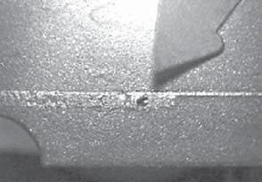

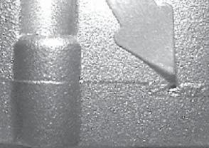
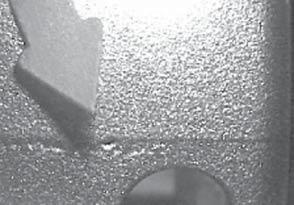
199 Quality Assurance 7 NADCA Product Specification Standards for Die Castings /


200 Quality Assurance 7-16 NADCA Product Specification Standards for Die Castings / 2015
201 Quality Assurance If specific porosity will be detrimental to the use of the product being cast, the die caster must be informed of the areas that will require special control to reduce the incidence of such porosity. This information must be supplied in detail at the time of the RFQ, so that measures such as part design change requests, accountability for higher scrap or utilization of special processes, can be taken in advance of die design and construction. Since zero porosity is virtually impossible to achieve in a die casting, the size, nature and location of permissible porosity should be identified by the customer, with the agreement of the die caster. The user should be agreeable to accepting a specified amount of porosity in areas of the casting where it does not impact form, fit or function. See figure Note: ASTM Nondestructive Testing Standard E505 provides reference radiographs for inspection of aluminum and magnesium die castings. 7.2 Parting-Line Porosity It should be noted that some parting-line porosity may exist in some die castings. Whenever possible, castings should be designed to avoid parting lines on complex functional or cosmetic surfaces. Special measures will need to be taken when this cannot be done, such as adding changes in the parting line, adding a CAM-type movement or a hand-removal operation to blend surfaces. Parting line porosity should not be confused with parting line break-out (see figures 7-17A & B). 8 Pressure-Tight Castings Pressure tightness (leakage) requirements for components add to die design and casting costs and should not be specified unless required for the application. When a pressure-tight die casting is desired, the customer should specify at the time of quotation the pressure the die casting is expected to withstand and the relevant testing method to be employed. Common leak testing methods for die castings include pressurized air bubble testing (to discover the location of the leak), gas pressure decay and mass flow testing (to determine the magnitude of the casting leakage in pressure loss or flow rate per unit time), and helium detection probe (when very low leak rates are required). When the die casting is expected to withstand specified pressures, the die caster can offer pressure testing of a statistical sample of parts, 100% sampling or impregnating of parts to meet the pressure specification. If machining of the pressure-tight die casting is required, it must be recognized that impregnation may be required after machining. The die caster should be advised of the specific areas to be machined in advance of the die design. The die caster will not be responsible for machining, impregnating or testing costs if the machining is done by the customer. By mutual agreement, the die caster may accept for replacement or credit the die castings that have failed the pressure test after the machining and impregnation process. 7 NADCA Product Specification Standards for Die Castings /

202 Quality Assurance 7-18 NADCA Product Specification Standards for Die Castings / 2015

203 Quality Assurance 7 NADCA Product Specification Standards for Die Castings /

204 Quality Assurance 7-20 NADCA Product Specification Standards for Die Castings / 2015
205 Commercial Practices Section Contents NADCA No. Format Page Frequently Asked Questions (FAQ) Introduction 8-2 SECTION 8 2 Using Die Casting Specification Checklists Defining Quality Requirements Specifying Tolerances General Database Guidelines Die Casting Dies and Production Tooling Die Ownership Die Life, Maintenance, Repair and Replacement Credit Changes or Cancellations Die Retention and Removal Insurance Gaging First-Piece Acceptance Die Cast Production Part Orders Metal and Metal Pricing Acceptance of Orders and Reorders Changes, Cancellations and Errors Credit, Payment Terms and Taxes Packaging and Delivery Limitations on Inspection Procedures Purchased Components Cast-in-Place Inserts Inventory Costs Price Adjustments Quotations and Metal Market Pricing Labor and Operating Costs Patent Obligations Intellecual Property Warranties Covering Die Castings Extent of General Warranty Limitations of Warranty Product Liability Production and Finishing Specification Checklists 8-14 Casting Production Specifications C Checklist 8-15 Casting Finishing Specifications C Checklist NADCA Product Specification Standards for Die Castings /
206 Commercial Practices Frequently Asked Questions (FAQ) 1) Who owns the die cast die? See page 8-4, Die Ownership. 2) Are there checklists available that can be used for cast or finished specifications? See pages 8-14 and 8-15 for checklists. 3) How long do dies last? See page 8-5 and 8-6, Die Life, Maintenance, Repair and Replacement. 4) Are there any recommendations for creating CAD data files? See page 8-3, General Database Guidelines. 5) What is involved with die maintenance/repair/replacement? See page 8-5 and 8-6, Die Life, Maintenance, Repair and Replacement. 1 Introduction In specifying die cast production, the purchase contract can be viewed as the purchase of a comprehensive engineering service from the die caster who will use the purchaser s tool to convert metal to the precise form desired by the purchaser. The die caster will usually provide other important services, such as designing, constructing or maintaining the tool and performing machining and surface finishing operations on die cast parts. Sub-assembly services may also be provided. The proposal and subsequent order for die castings sets forth a contract embodying the business practices governing a transaction in which custom engineered parts will be supplied on a continuing basis. Quality production of a high volume of custom parts, at the most economic level, involves a thorough understanding of the variables of the die casting process, its tooling requirements and related trimming, secondary machining and finishing operations. The physical properties and constants of metals and alloys used for die castings are set forth in Alloy Data (Section 3 of this volume) and should be referred to with other accepted metallurgical specifications. Aid in determining the detailed part design requirements to be specified for cost-effective production can be obtained from the Engineering and Design standards and guidelines in this volume (Sections 4, 5 and 6), together with other recognized engineering data. If geometric dimensioning is not being used on part prints, GD&T (discussed in relation to die cast parts in Section 5) is strongly recommended for optimizing quality and lowest costs. Tooling (Section 2) and Quality Assurance (Section 7) should likewise be reviewed well before drawing up final product specifications. Of equal importance to careful specification are the commercial arrangements which affect the buying of die castings. These trade customs have evolved from a half-century of industrywide production experience and have generally been accepted as good business practice. The commercial arrangements are normally found in the proposal and acknowledgement forms used by the North American die casting industry. These specialized inter-relationships, among others, govern the ability of the custom producer to supply die castings to specifications on prearranged quantity schedules at competitive levels on a continuing basis. They are described in this section together with convenient die casting product specification checklists. 2 Using Die Casting Specification Checklists The C-8-1 Checklist (Die Cast Product Specifications) and C-8-2 Checklist (Die Cast Surface Finishing Specifications), which appear at the end of this section, can help the purchaser to more clearly define the die casting requirements that will impact final costs. They can serve as a production guide to help provide accurate communication between the purchaser and the die caster, avoiding 8-2 NADCA Product Specification Standards for Die Castings / 2015
207 Commercial Practices misunderstandings later. The die caster should review these specification levels with the purchaser to assure that the most cost-effective level is selected and, if necessary, provide samples of various specification levels. 2.1 Defining Quality Requirements The checklists also mention the use of SPC and other inspection requirements. It is highly desirable to define such requirements so there is no question about record-keeping responsibilities. While most die casters use these techniques regularly, some purchasers have special requirements (ie. critical feastures) that must be defined early in the process. When using statistical techniques for quality control, it is important for the purchaser to specify the parameters when requesting a price quotation. For example, general definitions of process capability, such as Cpk, can affect tooling dimensions that are built towards one side of the tolerance to allow for future die wear. These dimensions can vary in one direction only, as in the outside dimensions of a cavity (see Moving Die Components Section 4A). When applying general definitions in this situation, the tool will appear to be out of limits, while it is actually built to high quality standards for long life. It is most important that agreement on procedures be reached prior to establishment of the quality standards. The costs for the quality level of a feature are calculated by the die caster during the quoting process, and any changes in standards at a later time may require a revision to the quotation. Many of the specifications, such as the quality of a surface finish or the severity of internal porosity, are subjective. The methods of establishing subjective standards can vary considerably, but it is always beneficial to spend the effort required to define the standards as closely as possible. One way of defining subjective standards is to define borderline acceptable and acceptable samples, which should be retained as limit samples by the customer and the die caster. In addition, it is desirable to have pictures or a complete written description of the defects that would cause rejection. Such provisions can be improved upon during the initial production phase. 2.2 Specifying Tolerances It is well known that the die casting process can achieve very high dimensional precision. The Engineering & Design Tolerance Standards for coordinate dimensioning of parts to be die cast (Section 4A) are presented at two levels: as Standard Tolerance and as Precision Tolerance specifications. Most die casters can improve on the Standard Tolerances, but a cost penalty in increased cycle times will often be the trade-off. Tolerance improvements are most directly related to part shape. If tolerance requirements are clearly discussed in advance with the die caster, precision tolerances can often be maintained for a cast part with significant improvements in product performance and reduced secondary machining and finishing operations. Machining processes should also be considered well before any order for the tooling is released. A careful evaluation of machining requirements can lead to a redesign for net-shape die casting or near-net-shape production, with a reduced number of operations or setups. 2.3 General Database Guidelines Computer Aided Design (CAD) databases usually consist of a two-dimensional drawing (2-D) and a three-dimensional model (3-D). Software compatibility is a common problem between customer and die caster. To expedite communications, the die caster and customer should be aware of each other s CAD software capabilities early on in the project. In the event that the die caster and customer do not utilize the same software packages, universal file formats can be used to communicate. Although there are many available, the most common formats are DXF or DWG (for 2-D drawings) and IGES or STEP (for 3-D models). Often, translation software is needed to convert files into the appropriate format. When databases are utilized for quoting purposes, these general guidelines apply: 1. If only a 2-D drawing is provided, it should contain dimensions and general views of the part and major features. Physical properties such as mass and part volume should be included as well. 8 NADCA Product Specification Standards for Die Castings /
208 Commercial Practices 2. If only a 3-D model is provided, the die caster should be able to retrieve dimensions and properties from the model. 3. Secondary operations, such as machining, can be included in the database or supplied separately. Some general requirements when databases are being utilized for tool construction: 1. When only a 2-D drawing is provided: 1.1. Drawing should contain complete dimensions of all features Parting line, draft, radii, datums and tolerance (dimensional and geometric) requirements should be clearly defined Secondary operations that are to be performed on the part and other requirements should be clearly stated. 2. When only a 3-D model is provided: 2.1. All necessary draft, parting line and radii should be included in the model. Ideally the 3-D model will indicate machined surfaces Lines and surfaces of the model should be connected within The 3-D model should be accompanied by a limited dimension part print that contains all tolerancing information and shows any secondary machining to be performed. An incomplete database could result in an inaccurate quote and possibly require considerable database manipulation, which leads to additional cost and extended lead-time. The die caster and customer should also indicate whether the 2-D drawing or the 3-D model controls the project. 3 Die Casting Dies and Production Tooling Any die casting can be produced in a number of different ways and every die casting plant possesses different equipment and utilizes a range of production techniques. Optimum economy and maximum efficiency for the production of any die casting, therefore, must be considered in the light of the particular equipment with which it will be produced. The experience, technology, skill and ingenuity of the die caster are all involved in selecting the method of production on which the proposal is based. Each die caster sells die casting dies, trim dies and specialized production tooling on its own individual terms and conditions. Normally, these terms provide for an advance payment for dies and tooling, with the balance paid upon receipt of, or approval of, a sample produced from the dies and tools. Length of time for approving parts to be 30 days if not otherwise agreed upon between die caster and customer. 3.1 Die Ownership Generally, the purchaser of die castings will retain ownership of the die casting die, even though the die remains with the die caster. It has also been the custom that the design and construction of the die casting die are performed by the die caster to its own specifications, even though the purchaser owns the die. The custom generally works to everyone s advantage. The practice has developed because most purchasers lack the extensive experience and expertise required to design and build a die casting die that will produce acceptable castings. There are also a number of features of the die that need to precisely match the die casting machine selected by the die caster. These die construction and ownership practices are generally being maintained today, although other options are available for the purchaser. The increasing technical capacity of designers is making it possible for a knowledgeable purchaser to contract for the design and construction of a die from a tooling vendor, then select a die caster to run the tool. However, this procedure can potentially create a number of serious conflicts with the eventual die caster. For example, if the castings are of low quality, who is responsible? The problem could stem from die design, die construction or production operations. Consequently it is preferable for the die caster to be responsible for die design and construction. In addition to eliminating questions of responsibility, this procedure also ensures that the die will match the casting equipment. In addition, the die caster has a vested interest in building a high-quality die that will give few problems in production. 8-4 NADCA Product Specification Standards for Die Castings / 2015
209 Commercial Practices The die casting die, usually owned by the purchaser, is housed and maintained at the die caster. The die caster will be responsible for loss or damage to the die and tooling while housed at the die caster s facility. Some die casters offer the option of joint ownership of the die. In either case, there are some considerations that should be addressed during the purchasing discussions. An ownership record should be established by both parties, which will include a description of the die and all additional components of the die. Each die should have a method of identification, which is best done with engraving or welding (riveted tags can come off). Typically a number is assigned to the die by the die caster, which is engraved on the die, slides and cores and included in the purchaser s record of the die. All components purchased originally with the die should be noted in the record, such as shot sleeves or extra slides or cores. These components usually wear out much more rapidly than the rest of the die and they may be worn out and unavailable if the die is claimed by the purchaser. The question of Tool Ownership as well as Replacement is often overlooked when general discussion begins at the start of a possible new project. Since there are multiple types of tools available for the die cast process the following descriptions for tooling and ownership is to provide a starting point for those decisions. New tools are generally paid for by the Customer, the Die Caster is responsible for normal maintenance and care (as the caretaker), the customer (as the owner) for replacement. It is the responsibility of the die caster to inform the customer of any atypical maintenance or care required. If the customer elects not to follow the maintenance advice of the die caster the quality of the part could suffer. In today s rapid development world sometimes who owns what is not clear. In the following cases an example will be given as to typically who owns what portion of the tool. 1) Rapid Tooled projects frequently use a tool (mold base) that is owned by the die caster and becomes a type of Universal Holder for Die Cavity inserts (for multiple customers). The inserts that are used to make the part configuration are owned by the customer and frequently will have a shorter tool life than Production made tooling. 2) For Unit Dies, the Master or Universal Holder (as above) is usually owned by the Die Caster and the individual units and their inserts are owned by the Customer. As long as a Unit Die is the equivalent of an Industry standard it should be able to move to a new die caster if needed without major cost factors involved. 3) Dies by themselves are owned by the Customer and may have different shot life attached to them based on part design and function. Replacement is usually limited to the cavity inserts but in certain cases could be the entire die. Normally the customer is notified at the 1/2 life that replacement is needed so that enough time is allowed to get the replacement components approved before the original tool wears out. This can be paid for at the time of construction of the replacement or in cases of a very high volume part an amortization account may have been set-up. This type of account allows for a small amount to be added to the part price that will cover the cost of the replacement when needed. It becomes the Die Caster s responsibility to manage tool replacement and to notify the Customer when new replacements are submitted for approval. Tooling Amortization must be started at the time of the fist part being produced for sale so that the account can cover the cost of replacement start and the balance due at approval. If it is not started at this time the tool may have to be pushed beyond normal life to pay for a new tool and to not interrupt Customer production. This usually results in added operations to the part which can increase costs. This process does not work with inherited tooling because of questions concerning actual shot count on the tool but can be applied after the first replacement is completed. Either the Customer or the Die Caster can be holder of the amortized funds for replacement but usage terms need to be clearly defined. The Die Caster and the Customer need to agree on both the initial tool and replacement plans (as needed) and payment terms at the start of the project so that on-going needs are met and ownership is clear Die Life The purchaser should be aware that the life of a die can be unpredictable. Die life is a function of many factors. Among them are part design, part configuration in the die, part quality expectations, NADCA Product Specification Standards for Die Castings /
210 Commercial Practices release quantity, type of tool steel used for the die, the heat treatment of the die and the type of alloy being die cast. Even when the die caster makes every effort to extend die life, early failure is still possible. It is also possible for a die to have an unpredicted very long life. An understanding of expected die life should be discussed in the initial phases of a project. Progressive die casters can provide tool steel specifications and heat treat specifications that have been developed through extensive NADCA research programs. It is recommended that the purchaser reference these specifications for the building and heat treating of the casting die. The specifications include recommendations for stress relief during machining, the removal of the white layer after EDM operations and a number of other considerations. When tooling is procured through a reputable die caster, tooling costs may be somewhat higher than if a purchaser dealt directly with the tool builder. The die caster will be closely involved in evaluations and decisions that will translate the product design into the optimum die casting die for successful production. The increased costs almost always represent a bargain in terms of overall costs during the life of the die. An inexperienced purchaser who purchases tooling purely on a cost basis will find that the costs over the life of a die are significantly higher because of a lower-quality tool, although this will not be immediately apparent when the tool starts running. It cannot be emphasized too strongly that good quality tooling will cost more in the beginning but pay for itself many times over in the life of a typical die casting die. Note: Computer software is available for flow simulation, thermal and distortion analysis Die Maintenance, Repair and Replacement The responsibility and criteria for maintaining tooling, on the one hand, and replacing the tooling, on the other, should be understood. In some cases, the die replacement cost is requested to be amortized into the piece price. The most common way of structuring this portion of the contract is for the die caster to provide minor maintenance, and the purchaser to provide major repair and replacement. Minor maintenance is generally described as run-to-run maintenance of a serviceable die to maintain die casting production. Major maintenance would cover the replacement or rebuilding of an entire die cavity, die section, or complex core slide that makes up a significant percentage of the casting detail, or major die resurfacing. Most die casters have a preferred way of handling maintenance and it should be made clear. The rapid wear components should be covered in the die maintenance understanding between the purchaser and the die caster. These components are frequently replaced by the die caster, although each purchaser should expect to make an individual agreement for each casting. If the components are replaced by the die caster, ownership usually remains with the die caster, although this can vary for individual agreements. The purchaser should review the die maintenance practices of the die caster and agree on the expected maintenance. For example, if the purchaser expects the die to be stress relieved after a certain number of shots, then the die caster should be aware of this requirement so that it can be included in the costs. Die preheating practices, gating design and die temperature control are particularly important to long die life. Reviewing these practices may be difficult, but there are some steps a purchaser can take. 1. The purchaser should ascertain the die preheating practices of the die caster. The best results are achieved by preheating dies to a specified temperature, depending on the alloy being cast, before the first casting is made. 2. Smooth metal flow at the correct velocities from a carefully designed gate is important to reduce the die erosion at the gate, as well as having a significant effect on casting quality. Die erosion can be repaired by welding, but the onset of welding significantly reduces the ultimate life of the die. 3. The die caster should be able to discuss the use of good die design practices with the purchaser. A die caster using trial and error without calculations for gating will have many more problems with die erosion and part quality than one who uses calculation techniques developed by NADCA or other authorities. 8-6 NADCA Product Specification Standards for Die Castings / 2015
211 Commercial Practices 4. Die temperature control, involving careful cooling line control and proper cooling line placement, will influence casting cycle time and have an important effect on casting quality. Working with a quality die caster assures the purchaser that all aspects of die design and construction follow practices that maximize production as well as die life. 3.3 Credit The die caster generally reserves the right to change his terms of payment if a change in the customer s financial condition requires it. Such changes are usually requested in writing and, when necessary, may require the die caster to stop design and/or construction pending agreement. 3.4 Changes or Cancellations If any changes are required by the purchaser to finished die casting dies or production tooling which deviate from the original print and/or model provided for the dies and tooling at the time of quotation, the die caster reserves the right to requote the quality, expected die life, cost and delivery of the tooling. Any changes to the order must be agreed to by the die caster, in writing. The die caster will usually require some payment for cancelled orders. Payment is necessary to compensate the die caster for costs of work in process to the date of cancellation and commitments made by the die caster for purchases relating to the order. 3.5 Die Retention and Removal It is customary for the die caster to retain control and possession of die casting dies and production tooling. Since the full cost of engineering, designing, obtaining, and maintaining the die casting dies and production tooling is not fully reflected in the charges to the purchaser for these items, an additional charge may be necessary for these unreimbursed costs if the die casting dies and production tooling are removed prematurely from the die caster s plant. It is also customary to allow die casting dies and production tooling which have not been used for three consecutive years for production of die castings to be scrapped following proper notification, via certified mail, to the purchaser by the die caster. Rules for the accessibility of the die should be established. If the die is to be claimed by the purchaser, it should be available after notice has been provided, and all outstanding invoices due the die caster are paid in full. 3.6 Insurance It is customary for the insurance of die casting dies and production tooling to be the responsibility of the purchaser, unless specifically agreed upon, in writing, to the contrary. Die casters normally have liability insurance protection against fire and theft or vandalism. However, fire insurance usually excludes tools, which do not burn, except for the clean-up costs following a fire. Insurance should be reviewed in each case, and business interruption in case of fire may need to be considered. Die casters will provide worker s compensation insurance as required by law. 3.7 Gaging Good gaging is critical to obtaining good quality parts, both during the process and at final acceptance, and can also help reduce part cost, especially if a casting is heavily machined. It is important that this aspect be discussed early in the project. The die caster can be expected to furnish standard gages. The purchaser is expected to furnish any special gages needed in the inspection process, such as those required for determining conformance to feature and location specifications and any gages needed for functional or statistical requirements. All gages and gaging methods should be agreed upon in advance by the purchaser and die caster, including any need for duplicate gages. This will aid in both part function and fit, in instances where the die casting will be mated or assembled with other parts not manufactured by the die caster. 8 NADCA Product Specification Standards for Die Castings /
212 Commercial Practices 3.8 First-Piece Acceptance After the first die cast samples are received from a die casting die, the die caster or purchaser will usually be required to measure the samples and verify that they meet specifications. Modifications from the original print which have no effect on part function or appearance can be discussed at this time to ensure that high production rates can be maintained and premature die maintenance avoided. Procedures for handling changes in the print specifications for the die casting should be agreed upon. Any costs and delivery delay incurred by such changes should be quoted by the die caster immediately after they are received. Authorization for the changes should be given by the purchaser in writing on each change order. 4 Die Cast Production Part Orders The commercial terms of the contract items and conditions between the purchaser and the die caster for die cast part production are discussed below. Note that the trade customs outlined represent the historic and customary practices prevailing in the die casting industry. Contract forms of individual die casters will vary in some details. A model of terms and consitions can be found at Metal and Metal Pricing Quality metal is the foundation for good castings. Even a chemical analysis does not fully define all the metal quality specifications that are necessary for good die casting. Low-cost, low-quality metal cannot be expected to meet all die casting requirements. For example, when aluminum or magnesium alloy does not meet established criteria, machining may be more difficult or surface corrosion accelerated. When zinc alloy does not meet established criteria, mechanical properties will be progressively and seriously reduced in use with time. Metal price is commonly established from quotations from an approved metal supplier, or based on known industry indicators such as the daily American Metal Market, the London Metal Exchange, Platts or other major markets. If the purchaser elects to use an industry indicator, he may forfeit the advantage of spot metal buys at lower than market price. 4.2 Acceptance of Orders & Reorders Acceptance of Orders Proposals for the production of die castings are prepared on the basis of the specifications and prints known at the time of estimating. Die casting proposals are, therefore, for immediate acceptance on the basis specified. Similarly, since orders are accepted on the basis of the requirements known at the time of the order, changes from the original proposal on which the order is based may result in the need for price adjustment for the parts. The die caster reserves the right to review all orders before acceptance. The proposal, the order and its acceptance, signed by an authorized representative of the die caster, constitute the entire contract with the exception that, when any provisions of the order conflict with the proposal, the proposal and acceptance always prevail. Modifications, changes, additions, cancellations or suspensions of an order are not binding upon the die caster, unless accepted in writing by an authorized representative of the die caster and upon terms that will indemnify him against all loss Reorders Reorders for die castings are covered by the same conditions as was the original order, provided no revised proposal and acceptance has intervened. Pricing of reorders will, of course, be affected by quantity alloy, labor and other costs prevailing at the time the reorder is placed. 8-8 NADCA Product Specification Standards for Die Castings / 2015
213 Commercial Practices 4.3 Changes, Cancellation and Errors Changes or Cancellation Any changes to the order deviating from the original basis upon which the order was accepted must be agreed to, in writing, by the die caster. These changes may result in the adjustment of prices. Changes could include, but are not restricted to, delivery dates, quantities, release dates, part prints, etc. The die caster usually will require some payment for cancelled orders. Payment is necessary to compensate the die caster for costs of work in process to the date of cancellation and commitments made by the die caster for purchases relating to the order, including dedicated equipment specifically acquired for a cancelled project. Any change to the delivery schedule or release dates beyond 90 days must be subject to negotiation between the die caster and the customer Errors Clerical errors are, of course, subject to correction regardless of whether they favor the buyer or the seller and enforceable if discovered within a period of one year. 4.4 Credit, Payment Terms and Taxes Credit The die caster generally reserves the right to change terms of payment if changes in the customer s financial condition requires it. Such changes are usually requested in writing and, when necessary, may require the die caster to stop production or suspend shipment pending agreement Terms of Payment Each die caster sells its products on its own individual terms and conditions. Shipments are generally FOB the city in which the die casting plant is located. Payment is normally net 30 days with provision for metal market and escalation clauses Taxes and Duties Sales or use taxes, excise taxes, taxes on transportation, other direct taxes and applicible duties are the responsibility of the purchaser whether such taxes are federal, state or local. 4.5 Packaging and Delivery Shipping Tolerances Since the die caster cannot determine in advance the exact loss factor in a particular run, it is generally recognized that he may manufacture and ship 10% over or 10% under the number of die castings ordered or released. If no deviation is to be allowed, with pricing affected accordingly, this should be so specified in the purchasing agreement Packaging Die castings are generally packed in bulk as the most suitable and economical method. Any special requirements, such as specifying layer packed, separated or cell-packed shipments, must be communicated to the die caster in the RFQ ; otherwise a price change may be required later. If recyclable packaging is required, it should be carefully spelled out in the quoting phase. While this type of packaging can have a positive impact on pricing, it may increase up-front costs. The die caster will be responsible for cleaning and reusing recyclable packaging. NADCA Product Specification Standards for Die Castings /
214 Commercial Practices Deliveries Unless otherwise specified, deliveries of die castings generally begin as soon as the die caster s schedules permit and, in the case of a new die, after approval of samples. Deliveries are made at a rate approximately equal to the capacity of the tools until orders are completed. The purchaser selects the method of delivery and, unless otherwise specified on the purchaser s order, the die caster will use his best judgement in routing the shipment and seeing that deliveries are effected as specified. Acceptance of the goods by the carrier shall constitute a delivery. Any charges in connection with postponement or cancellation of delivery are the responsibility of the purchaser. The purchaser will also be responsible for any additional costs of expedited or other special transportation as result of changes in delivery schedules not caused by die caster. Penalties upon the die caster for delayed delivery, whatever the cause, are not normally acceptable unless agreed upon at the time the order is being placed. Many die casters today can provide an electronic connection to high volume purchasers to facilitate placing orders, as well as provide bar coding. It is frequently desirable to anticipate emergencies and provide for backup tooling, a small amount of emergency inventory or some other way of addressing the catastrophic failure that can occur in any volume production process based on sophisticated tooling Lot Size versus Cost Because of the cost of setup, die casting is usually a high-volume process where the cost of a small lot is significantly increased by setup costs. It is therefore imperative that lot sizes be considered in the discussions of the purchasing contract. Each die caster will have his own costs for setup, so the break-even point for minimum lot sizes will vary among die casters. Some purchasers use consignment inventory agreements to address the reality of die setup costs and tooling life factors that are adversely affected by the short runs. Lot size should be considered in the early stages of determining the tooling requirements. For example, in some cases fewer cavities on a smaller die will result in lower tooling costs, lower setup costs and a smaller economical lot size. This may be more desirable even though the piece-price may be slightly higher. If small lot sizes are required often, quick setup aids, such as quick-disconnects, can be built into the tooling. Advising the die caster of small lot requirements at the time of quotation will enable him to optimize the use of these aids. It is desirable for the purchaser to take time to explore the options of economical lot size, costs of maintaining inventory and tooling options during the tooling quotation phase. Since there may be many options, it is suggested that the purchaser provide the die caster with those considerations that are important for the project and let the die caster propose several options. This will allow the die caster to maximize the efficiency of the equipment available in his plant and provide the most economical quote to the purchaser. 4.6 Limitations on Inspection Procedures Prints and Approved Samples Die castings may not be rejected because of variation from print dimensions if they are made to, and are unchanged from, approved samples with respect to dimensions, finish and analysis. When the purchaser has specified or approved the design, failure with regard to function or fitness for use shall be the purchaser s responsibility. If sample die castings have not been approved and conflicting models and prints have been submitted, the basis of acceptance shall be agreed to in writing Accuracy Die castings may not be rejected if they vary from finished sizes or dimensions within limits agreed upon. Where a very close tolerance or particular dimensional accuracy is specified, the permissible variations shall be agreed upon before die work is begun. In the absence of applicable standards, tolerances will be subject to the commercial variations generally prevailing in the industry NADCA Product Specification Standards for Die Castings / 2015
215 Commercial Practices Inspection and Sampling Procedures If specified and specifically acknowledged and agreed to by the die caster, die castings can be inspected on the basis of statistical quality control or other sampling procedures. Use of statistical quality control standards and other related procedures require specific detailing by prior mutual agreement on all aspects involved. 4.7 Compliance with Laws Die caster will comply with applicable laws, rules and regulations of the country where the casting is made. Die caster will provide customer with material safety data sheets and, upon request, provide other information reasonably required in order to comply with applicable laws. 5 Purchased Components Innovation in the design of die castings and flexibility in the industry s manufacturing process have led to the use of purchased components for insertion or assembly by the die caster. The procurement and subsequent responsibilities for the delivery and quality of such components lies with the purchaser of the die casting unless otherwise agreed upon and included in the quote and the order. These components may be insert cast as an integral part of the die casting or may be assembled to the die casting in a separate operation. 5.1 Cast-in-Place Inserts If the finished casting contains cast-in-place inserts, the responsibility of providing them to the proper specifications should be clearly defined. The design of the purchased component is the responsibility of the die casting purchaser and is subject to approval by the die caster. In many cases the clearances in the die will require that the insert tolerances be tighter than the purchaser would normally supply for the required end use. If the purchaser is supplying the inserts, provision must be made to ensure that all supplied inserts are within tolerance. An out-of-tolerance insert can seriously damage the die. 5.2 Inventory Costs Regardless of who purchases an additional component, there must be consideration given for in-process spoilage and rejects. As a result, the quantities of purchased components will always exceed the number of die castings purchased. It is understood that there are costs associated with handling, storing, counting and inspecting of purchased components. Inventory of purchased components required to meet the die casting purchaser s delivery schedule are the responsibility of the die casting purchaser. The labor cost for inserting or assembling the component is normally included in the quoted piece price. 8 6 Price Adjustments Because of the job-shop nature of production and the variation in product design and specifications, the prices for die castings are determined by the use of price estimating formulas. Each die caster employs an individual pricing formula constructed in accordance with their individual methods and costs. All price estimating formulas contain a number of factors which may require adjustment, upward or downward, because of conditions beyond the control of the estimator. Significant unexpected increases in the cost of either natural gas and/or electricity may result in negotiated energy surcharges per mutual written agreement. NADCA Product Specification Standards for Die Castings /
216 Commercial Practices 6.1 Quotations and Metal Market Pricing Order Quotations Order quotations for die cast products, and die casting dies and production tooling necessary to make the die cast products, are normally valid for a fixed period of time. After this time has expired, the die caster reserves the right to requote based upon price adjustment provisions as discussed above. To establish a uniform basis of comparison, the estimated weight and monthly and/or yearly quantity requirements should be specified when soliciting quotations, and it should be requested that the material cost be itemized Metal Market Pricing Prices for die castings are based on the die caster s prevailing cost for the alloy specified on the day the estimate is prepared. In some instances, the die caster s quotation may make reference to various published alloy prices or other indicators. The cost for the alloy is subject to fluctuation beyond the control of either the purchaser or the die caster and the actual price charged for the die casting will reflect the changes required to adjust for all metal market variations. Similar adjustments may be made on each release and/or reorder. 6.2 Labor and Operating Costs Labor Costs Many die casting dies are in production over extended periods, often over many years. For this reason, the piece-part labor cost may change over the life of the order. If piece-part labor costs change after the date of the original price estimate, it is generally necessary to change the piece-part price for future deliveries. Customer schedules often are expanded and sometimes require production beyond the normal schedules of the die caster. Since all die casting prices are estimated on the basis of production at straight-time rates, an adjustment is generally required if premium labor rates are necessary to meet the customer s expanded needs. Die casting price estimates and quotations reflect labor costs based on continuous operation for the quantity specified for any delivery release. Reductions in scheduled deliveries or production interruptions by the customer, may affect labor and other piece part costs. In such cases, a price adjustment may be necessary Operating Costs Costs of outside services (such as painting, plating and machining), or of purchased supplies and components (such as inserts, packing materials and fasteners), or action of governmental or regulatory agencies may cause periodic increases in the costs of manufacturing. These added costs must be reflected in changes to quoted prices. Also, changes in acceptance criteria by the customer may significantly affect the die caster s operating costs, making an adjustment to the part price necessary. 7 Patent Obligations Die casting is essentially a conversion process by which metal shapes are produced for a purchaser. Therefore, if a die casting infringes, or is claimed to infringe on any letters patent or copyright, the purchaser must assume the responsibility involved. While the die caster does provide input into the design of the customer s component for die casting manufacturing feasibility, the die caster is not responsible for the design or functionality of the customer s product or device or for the design of the die casting as part of such product or device. The purchaser of die castings is liable for his own product or device and for all patent infringement claims relating to it or any of its parts NADCA Product Specification Standards for Die Castings / 2015
217 Commercial Practices Die casting proposal and acknowledgment forms generally include clauses which provide that the die caster shall be indemnified and held harmless of and from all expenses arising from all such claims. When patents, design or otherwise, are involved, they should be specifically called to the attention of the die caster. 8 Intellectual Property Die Caster is not required to provide any intellectual property used to produce parts for the purchaser. Purchaser has the right to use parts in purchaser s product. 9 Warranties Covering Die Castings 9.1 Extent of General Warranty Die casters, like other responsible manufacturers, stand behind their product. However, it should be understood that the die caster in assuming this proper responsibility focuses its engineering efforts upon the die cast manufacturing feasibility of the component, rather than the component s product function which is the responsibility of the purchaser. In general, die casters agree, at their option, to correct, replace or issue credit for, defective die castings, subject to specific limitations and exceptions. Reference NADCA Terms and Conditions for more details on warrenties. 9.2 Limitations on Warranty Processing After Delivery No warranty attaches to a die casting which has been altered, machined or finished after delivery to the purchaser by the die caster Reasonable Time No claim for defective die castings will be recognized unless made in writing within 90 days (or as agreed upon between die caster and purchaser) after delivery Returns Die castings claimed to be defective are not to be returned to the die caster without specific approval and inspection by the die caster. Returned goods accepted by the receiving department of the die caster are not exempted from the right of the die caster to inspect the die castings or to determine the extent, if any, of his liability General Limitations Losses, damages or expenses arising from the use of a die casting, or labor costs or other charges incurred outside of the die caster s plant, or transportation costs, as well as losses due to other causes, are not acceptable basis for claims against die casters under the warranty provisions. The Warranty as stated in paragraph 8.1, above, is limited to the repair or replacement of defective die castings or the issuance of credit for their return as stated. NADCA Product Specification Standards for Die Castings /
218 Commercial Practices 10 Product Liability Die casters cannot be expected to have technical knowledge relating to the end product of the many industries they service. While they may freely offer design services to make a product easier to manufacture, at no time does this imply a knowledge of the strengths, stresses or other forces that may be induced in the product s end use. This must be exclusively the liability of the buyer and design suggestions are offered by the die casters with this understanding. The die casting industry has always maintained the position that a die caster is not liable for the failure of a die casting in a buyer s product, if the part furnished to the buyer meets the prescribed specification. Die casters accept the responsibility of manufacturing a part to the buyer s specifications within the agreed acceptance level. This means the buyer will accept a percentage of parts that do not conform to the specifications. Die casters cannot be held liable for any failure in the end product because of the decision on the part of the buyer to use statistical quality control in its incoming inspection. If a buyer approves a sample for production of parts that do not meet specification in any way, this approval constitutes a change in specification and the die caster s responsibility is then altered to only meet this altered specification. It is anticipated that the buyer will indemnify and defend the die caster from any damages or claims arising from the use of die castings or other goods produced to the buyer s specifications. 11 Production and Finishing Specification Checklists The C-8-1 Checklist (Die Cast Production Specifications) and C-8-2 Checklist (Die Cast Surface Finishing Specifications) appear on the following pages. It is recommended that, prior to final quotations, and always before any die design commences, the casting requirements defined by these checklists be reviewed with the die caster, together with the specifications and procedures listed in Section 7, Quality Assurance. All of these items impact final costs and should be thoroughly discussed to assure accurate communication between the purchaser and the die caster NADCA Product Specification Standards for Die Castings / 2015
219 Commercial Practices NADCA C CHECKLIST Casting Production Specifications To be used in consultation with your caster (Use in combination with Checklist C-8-2)* Checklist for Die, SSM and Squeeze Casting Production Part Purchasing This Production Checklist provides a convenient method for assuring important factors involved in purchasing cast parts are evaluated and clearly communicated between the purchaser and the caster. It should be used as a supplement to the essential dimensional and alloy specifications detailed on part prints submitted for quotation, since the listed factors directly affect the basis on which the casting quotation is made. The checklist may be reproduced for this purpose. Your caster will clarify any item requiring further explanation. This checklist provides a numbering system in which the lowest numbered description for each requirement can be met at the lowest production cost, as follows: 1 No. Cost Effect This checklist is for use in consultation with your die caster prior to estimating production costs. Use in combination with the Finishing Checklist C-8-2. Also review Checklists T-2-1A and T-2-1B, for Die Casting Die Specification, in Section 2. Most economical basis for production 2 Involves additional work which may affect cost 3 Additional work which may increase cost 4 Special Requirements which may increase cost Part # A B C D E F G H I J Casting Cleanliness Cast Surface Finish Metal Extension (Flash) Removal Parting Line External Profile Metal Extension (Flash) Removal Cored Holes Metal Extension (Flash) Removal Ejector Pins Pressure Tightness Flatness 1 Some residue and chips not objectionable 2 Shop run blown reasonably free of chips but not degreased 3 Clean, dry and free of chips 4 Special requirements 1 Mechanical quality finish is not significant 2 Painting quality streaks and chill areas coverable with paint 3 Highest quality for electroplating, decorative finishing, O-ring seats 1 No die trimming break off gates and overflows 2 Die trimmed to within (0.38 mm) of die casting surface (See NADCA Guideline G-6-5) 3 Hand filed or polished flush with die casting s surface 4 Customer defined requirements (such as thermal, tumble or vibratory deburring, or shot or grit blasting) 1 Flash not removed 2 Flash trimmed to within (0.25 mm) of die casting surface 3 Flash to be machined 1 Not removed (See NADCA Guidelines G-6-4) 2 Crushed or flattened (See NADCA Guidelines G-6-4) 3 Removed from specific locations 1 No requirement 2 Pressure-tight to agreed-upon psi (kpa). Testing medium: 3 Other arrangements to be agreed upon 1 No requirement 2 To NADCA Standard specification tolerances (S-4A-8) 3 Critical requirement to NADCA Precision specification tolerances (P-4A-8) 4 Customer defined requirements Dimensions 1 Normal: per NADCA Standard specification tolerances 2 Semi-critical: Precision tolerances on specified dimensions, others Standard 3 Critical: Special tolerances to be agreed upon Customer s Receiving Inspection Packaging 1 No unusual inspection requirements no Statistical Quality Control 2 Statistical quality control: Acceptable at Cpk 1.33 or higher (or AQL over ) 3 Statistical quality control: Acceptable at Cpk 2.0 or higher (or AQL over ) 1 Not critical bulk packed 2 Layer packed, with separators, or weight restriction 3 Packed in cell-type separators or individually wrapped 4 Customer defined requirements NADCA Product Specification Standards for Die Castings /
220 NADCA C CHECKLIST Commercial Practices This checklist is for use in consultation with your die caster prior to estimating production costs. Use in combination with the Finishing Checklist C-8-2. Also review Checklists T-2-1A and T-2-1B, for Die Casting Die Specification, in Section 2. 1 No. Cost Effect Casting Surface Finishing Specifications To be used in consultation with your caster (Use in combination with Checklist C-8-1)* Checklist for Finished Die, SSM and Squeeze Casting Part Purchasing Most economical basis for production 2 Involves additional work which may affect cost 3-4 Additional work which may increase cost 5 Most difficult surface to cast on a production basis Part # This Finishing Checklist provides a convenient method for assuring that important factors involved in the surface finishing of cast parts are evaluated and clearly communicated between the purchaser and the caster. It should be used as a supplement to the essential dimensional and alloy specifications detailed on part prints submitted for quotation, since the listed factors directly affect the basis on which the casting quotation is made. The checklist may be reproduced for this purpose. Your caster will clarify any item requiring explanation. This checklist provides a numbering system in which the lowest numbered description for each requirement can be met at the lowest production cost, as follows: K L Casting Insert 1 No insert used in cast part 2 Inserts required, to be supplied by customer at 10% overage 3 Inserts required, to be supplied by caster Parting Lines M Surface Preparation N Plating, Anodizing or Other Special Finish Painting 1 Polishing not required 2 Polish only where marked on drawing 3 Polish all parting lines (except as noted) 1 No buffing required 2 Mechanical (burnishing, tumbling, etc.) 3 Buff as indicated on drawing 1 Protective Only Specify: 2 Decorative Paint Specify: 3 Severe Exposure Protection Specify: 1 Heavy Paint, Protective Only Specify: O P Q R Environmental As-Cast Surface See NADCA Guidelines G-6-6 Special Requirements 2 Decorative Paint Specify: 3 Application requires base coat or special treatment: Specify: 1 Normal interior use only 2 Exposure to weather Specify: 3 Exposure to unusual chemistry Specify: 1 Utility Grade surface imperfections acceptable, nondecorative coatings 2 Functional Grade slight, removable surface imperfections, heavier coatings 3 Commercial Grade removable imperfections 4 Consumer Grade no objectionable imperfections, as agreed upon, when viewed under normal lighting conditions at feet viewing distance 5 Superior Grade specified average surface finish value of microinches, per print For special flash removal requirements, see Checklist C-8-1, items C & E For special packaging/weight restrictions, see Checklist C-8-1, item J 8-16 NADCA Product Specification Standards for Die Castings / 2015
221 Casting Examples SECTION 9 Aluminum 9-2 Pistol Frame 9-2 Rocker Arm 9-2 Right/Left Hand Bracket 9-2 Endbell 9-3 Engine Base Bracket 9-3 Water Passage 9-3 Heat Sink Front & Back 9-4 Chassis 9-4 B Pillar 9-4 Trimmer Deck Housing 9-5 RFU Enclosure 9-5 Impeller 9-5 Lower Crankcase 9-6 Differential Carrier 9-6 Beta Crankcase Right & Left 9-6 Scooter Monocoque Frame 9-7 Rear Wheel Drive Northstar Block Casting 9-7 Power Condition Module Chassis 9-7 MMC Brake Drum 9-8 AWD Clutch Housing 9-8 RWD Transmission 9-8 Magnesium 9-9 Frame 9-9 Head Node 9-9 Fishing Reel 9-9 Clutch Cover 9-10 Camera Assembly 9-10 Hand-Held Computer Housing 9-10 Gear Case Housing Assembly 9-11 Lock Housing 9-11 Fairing Support Bracket 9-11 Seat Back and Cushion 9-12 Lift Gate Inner Panel 9-12 Cross Car Beam for Instrument Panel 9-12 Oil Tank 9-13 SAWZALL Gear Case Assembly 9-13 Zinc 9-14 Knot 9-14 Bracket 9-14 Faucet Handle 9-14 Connector 9-15 Kitchen Faucet Hub 9-15 Fuel Fitting 9-15 Reverse Valve Casket 9-16 Casket Arm 9-16 Display Frame Component 9-16 Outside Cover 9-17 Front Plate L Connector Housing 9-17 Rearview Mirror Mount 9-18 Steering Wheel Ignition Lock Housing 9-18 Headlamp Visor 9-18 Camera Bracket 9-19 ZA (Zinc-Aluminum) 9-20 Tool Housing & Components 9-20 Transmission Shift Selector Tube NADCA Product Specification Standards for Die Castings /


222 Casting Examples Aluminum Part Name: Application: Part Weight: Alloy: Comments: Customer: Pistol Frame 0.22 Caliber Pistol 0.35 lbs. A380 Part was previously machined from stock. This is the first aluminum die casting used by Smith & Wesson. Smith & Wesson Aluminum Part Name: Application: Part Weight: Alloy: 383 Comments: Customer: Rocker Arm Honda Civic Engine 0.48 lbs. Process improvements and strict attention to detail resulted in cost savings on these high integrity, near porosity-free parts. The parts include a special wear insert chip and meet very tight specifications. Honda of America Mfg., Inc. Aluminum Part Name: Application: Part Weight: Alloy: Comments: Customer: Right/Left Hand Bracket BRP Skidoo 0.75 lbs. Aural-2 Part was previously made from low pressure permanent mold with extensive machining. High vacuum die casting created a heat treatable and weldable part for structural application, requiring minimal machining. Overall piece price reduction was on the order of 40%. BRP Skidoo 9-2 NADCA Product Specification Standards for Die Castings / 2015


223 Casting Examples Aluminum Part Name: Application: Part Weight: Endbell Alloy: 380 Comments: Customer: Air Compressors 0.85 lbs. Major tooling and process improvements resulted in scrap reduction, increased cost savings, production and quality. Completed cast units highly competitive in the market against lower entry models produced using stamped steel. Devilbiss Air Power Company Aluminum Part Name: Application: Part Weight: Alloy: Comments: Customer: Engine Base Bracket Honda Accord Engine 6.2 lbs. ADC3SF jointly developed with Honda, compatible with SF36, Aural 2 Replacing a previously stamped, 16 piece part, the new part is 27 in. long, thin-walled, with screw bosses, eliminating the welding operation and reduced weight by 43.6%. Honda Aluminum Part Name: Application: Part Weight: Alloy: 383 Comments: Customer: Water Passage Honda Civic Engine lbs. The Water Pasage hose mating surface is cast to specifications allowing the shipping of the part to the customer without any machining to the snout. This tight tolerance allows a cost savings to the customer. The customer saves the cost of machining for the snout, which is estimated at a 23% cost savings. Honda of America Mfg. Inc. 9 NADCA Product Specification Standards for Die Castings /


224 Casting Examples Aluminum Part Name: Heat Sink Front & Back Application: Garmin G-1000 Flat Panel Flight Display Part Weight: 1.91 lbs. Alloy: 360 Comments: Customer: Parts are assembled to collect & disperse heat from an LCD unit. Converted from machined parts to die castings. Increased production rate & reduced piece part cost. First time use of aluminum heat sink for this type of application. 360 alloy was selected based on it s corrosion resistance which protects the assembly from oxidation & other corrosion resulting from frequent atmospheric changes experienced by components used in general aviation. Painting or coatings are not required & are ready for assembly upon arrival at customer location. Garmin International Aluminum Part Name: Application: Part Weight: Chassis Human Transporter 8.2 lbs. Alloy: 380 Comments: Customer: The casting is produced to net shape and meets strict specifications. True position tolerances on critical dimensions were reduced resulting in reductions in machining and substantial cost savings. Segway Aluminum Part Name: Application: Part Weight: B Pillar Automotive Structural Support 9.2 lbs. Alloy: 380 Comments: Customer: A new part cast for automobile body framing support application. Yields weight savings benefit over fabricated steel components. 9-4 NADCA Product Specification Standards for Die Castings / 2015
, cycle time reduction (52")


225 Casting Examples Aluminum Part Name: Application: Part Weight: Trimmer Deck Housing Walk Behind Trimmer 9.2 lbs. Alloy: 380 Comments: Customer: As compared to a previous die casting design and tooling design, newly designed tooling allowed for scrap reduction (34%), cycle time reduction (52 sec.) and weight reduction (2 lbs.). Garden Way, Inc. Aluminum Part Name: Application: Part Weight: Alloy: 413 Comments: Customer: RFU Enclosure Microwave Communications 15.8 lbs. Formerly produced as an investment casting. Provides heat dissipation and electrical conductivity. Die casting reduced lead time and machining requirements. Harris Corporation, Microwave Communications Division Aluminum Part Name: Application: Part Weight: Alloy: Comments: Customer: Impeller Industrial/Commercial Blower lbs A380 Impeller used in industrial and commercial blowers. The application of the die cast part enabled the unit to operate at higher speeds, with less noise, while reducing the amount of secondary machining. Ametek Rotron 9 NADCA Product Specification Standards for Die Castings /


226 Casting Examples Aluminum Part Name: Application: Part Weight: Alloy: Lower Crankcase Motorcycle lbs. LM2 to JVM Specifications Comments: Redesign of original T120, 1959 Bonneville high performance version of Triumph s 650cc twin. Eliminated costly secondary machining operations, additional engine parts and fully utilized the benefits of high pressure die casting process. Customer: Triumph Motorcycles Aluminum Part Name: Application: Part Weight: Alloy: Comments: Customer: Differential Carrier Independent Rear Suspension 16.5 lbs. ADC-12 -T6 Heat Treatment Past generation was an iron casting. First high volume squeeze casting used in an independent rear suspension axel carrier. Squeeze casting decreased weight by 22 pounds over cast iron process. Visteon Corporation Aluminum Part Name: Application: Part Weight: Alloy: 383 Comments: Customer: Beta Crankcase Right & Left Motorcycle 16.8 lbs. These net-shape, complex castings were converted from the permanent mold process to meet stringent specifications of improved quality, pressure tightness, cosmetic appearance, higher volume and cost reductions. Harley-Davidson 9-6 NADCA Product Specification Standards for Die Castings / 2015


227 Casting Examples Aluminum Part Name: Application: Part Weight: Alloy: Comments: Customer: Scooter Monocoque Frame Honda Scooter Super Sport 23.4 lbs. JIS ADC12; 383 equivalent Previously fabricated from steel sheet stamping and pipes. Die casting provided weight savings and cost reduction. Honda R&D Co., Ltd. Aluminum Part Name: Application: Part Weight: Alloy: Comments: Customer: Rear Wheel Drive Northstar Block Casting Rear Wheel Drive Northstar Engine lbs. A380 GM Powertrain Aluminum Part Name: Application: Part Weight: Power Conditioning Module Chassis Computer/Electronics 2.3 lbs. Alloy: 380 Comments: Customer: Originally machined from a roughly shaped ingot, this chassis gained significant cost savings after being converted to an aluminum die casting. Novatel Wireless Technologies, LTD 9 NADCA Product Specification Standards for Die Castings /


228 Casting Examples Aluminum Part Name: Application: Part Weight: Aluminum MMC Brake Drum Commercial, Military, and Special Vehicles 38.5 lbs. Alloy: A356.2 Comments: Customer: Originally produced in cast iron. A unique horizontal squeeze cast process allowed a selectively placed ceramic preform to be infiltrated, creating a selectively reinforced, Metal Matrix Composite (MMC) aluminum brake drum. The new brake drum weights at least 45% less. Century 3+ Inc. Aluminum Part Name: Application: Part Weight: Alloy: Comments: Customer: Automotive AWD Clutch Housing Automotive 2.4 lbs. ADC12-T5 Originally produced as a multi-step forged steel housing, but this part was successfully convert this part to an aluminum squeeze casting. The new squeeze cast design incorporated 33 spline teeth with 0.1 degree draft. A significant mass reduction was obtained resulting in better fuel efficiency and reduced inertia for improved all wheel drive engagement response time. Borg Warner TTS, PTC Aluminum Part Name: Application: Part Weight: Alloy: Comments: Customer: RWD Transmission Automobile Industry 37.4 lbs. A380 Utilizes a unique process, involving 2 cast-in steel tubes, which have to be inserted in the ejector die and maintain location. Chrysler 9-8 NADCA Product Specification Standards for Die Castings / 2015


229 Casting Examples Magnesium Part Name: Application: Part Weight: Alloy: Comments: Customer: Frame Novatel Expedite Modem 0.01 lbs. AZ91D Converted from a plastic part. The magnesium casting eliminated a plastic part sandwiched between two metal plates and held together with self tapping screws, resulting in cost savings to the customer. Novatel Wireless Technologies, LTD Magnesium Part Name: Application: Part Weight: Alloy: Comments: Customer: Head Node Mountain Bike 0.22 lbs. AZ91D Originally designed as two aluminum investment cast parts, this unique die cast mag design and application yields a 30% weight savings, part and assembly cost savings, better consistency in impact and fatigue and better performance. Cannondale Magnesium Part Name: Application: Part Weight: Alloy: Comments: Customer: Fishing Reel Ardent XS Fishing Reel 31.3 grams AZ91D Converted from plastic & die cast aluminum components. Complex geometry & varying wall thickness. Tooling uses 3 slides to form entire exterior of part. Tight tolerance machining of bores and surfaces for mating components. 100% made in USA (Components & Assembly). Marsh Technologies, Inc. 9 NADCA Product Specification Standards for Die Castings /


230 Casting Examples Magnesium Part Name: Application: Part Weight: Alloy: Comments: Customer: Clutch Cover All Terrain Vehicle Clutch 0.44 lbs. AZ91D A conversion from aluminum die casting to magnesium die casting resulted in a weight reduction of 45% and a significant cost reduction by eliminating machining. Polaris Industries, ATV Div. Magnesium Part Name: Application: Part Weight: Alloy: Comments: Customer: Camera Assembly Digital Camera 0.48 lbs. AZ91D Originally designed as aluminum investment cast parts, the design complexity and required precision mandated a transition to magnesium die cast parts. Eastman Kodak Magnesium Part Name: Application: Part Weight: Alloy: Comments: Customer: Hand-Held Computer Housing Hand-Held Computer Over 0.5 lbs. AZ91D Telxon Corporation 9-10 NADCA Product Specification Standards for Die Castings / 2015


231 Casting Examples Magnesium Part Name: Application: Part Weight: Alloy: Comments: Customer: Gear Case Housing Assembly Automatic Power Pruner 0.64 lbs. AZ91D Magnesium was chosen for it s strength and low weight for this application over plastic and aluminum. Bearing diameter tolerances of are required and eliminate machining and masking cost. Echo Magnesium Part Name: Application: Part Weight: Alloy: Comments: Customer: Lock Housing SUV Tilt Steering Column 2.02 lbs. AM60B This die casting controls the tilt/telescoping features in the steering column and incorporates the ignition switch, shift lever and brake-shift interlock into one casting. In addition to tight dimensional control, the higher elongation in AM60B alloy provides good crash energy management. Visteon/Ford Magnesium Part Name: Fairing Support Bracket Application: Part Weight: Alloy: Comments: Customer: Buell 1125R Superbike 2.71 lbs. AZ91D This bracket provides support for the motorcycle s instrument cluster, windshield/cowling, direction signals and rearview mirror with increase copacity and a cost savings of aproximatly 26%. Buell Motercycle Co. 9 NADCA Product Specification Standards for Die Castings /


232 Casting Examples Magnesium Part Name: Application: Part Weight: Alloy: Comments: Customer: Seat Back and Cushion Luxury Car Seat Back and Cushion AM60B Magnesium Part Name: Application: Part Weight: Alloy: Comments: Customer: Vehicle Lift Gate Inner Panel Automotive 18 lbs. AM60 Replacing a stamped steel assembly, this large die cast magnesium lift gate reduced weight, added design flexibility and reduced assembly time through the integration of various components. The die cast lift gate is 54 x 52 inches. Ford Motor Co. Magnesium Part Name: Application: Part Weight: Alloy: Comments: Customer: Cross Car Beam for Instrument Panel General Motors Medium Duty Trucks 21.5 lbs. AM60B An example of maximizing the die casting process, machine and die to obtain substantial cost savings. The improvements resulted in weight savings & cost reductions through decreased material, downtime, and elimination of machining/ repair. General Motors Truck 9-12 NADCA Product Specification Standards for Die Castings / 2015


233 Casting Examples Magnesium Part Name: Application: Part Weight: Alloy: Comments: Customer: Oil Tank Snowmobile 2.03 lbs. AZ91D This magnesium oil tank replaces one that was a stamped aluminum and brazed assembly. The case is comprised of 3 separate magnesium die castings. It is lighter and more tunable than the aluminum it replaces. Arctic Cat Inc. Magnesium Part Name: Application: Part Weight: Alloy: Comments: SAWZALL Gear Case Assembly Power Tool.293 lbs. AZ91D Met customer requirements of eliminating machining and reducing cost of similar aluminum castings. Magnesium die casting holds dimensional tolerances that eliminate the need to machine. Customer: Milwaukee Electric Tool Co. 9 NADCA Product Specification Standards for Die Castings /


234 Casting Examples Zinc Part Name: Application: Part Weight: Alloy: Comments: Customer: Knot Marketing 5.5 Grams ZP5 This item s shape has never been industrially manufactured and displays ingenious part and tooling design. Nyrstar Zinc Part Name: Application: Part Weight: Bracket Electronics Enclosure Grams Alloy: Zamak No. 3 Comments: Customer: Converted from a machined aluminum alloy resulting in cost savings. The part is cast to net-shape thereby totally eliminating any machining. Zinc Part Name: Application: Part Weight: Faucet Handle Two Handle Lavatory Faucet 119 Grams Alloy: Zamak No. 3 Comments: Customer: Major cost savings were achieved from tooling changes, which eliminated trimming, reduced polishing the parting line and machining operations. Delta Faucet Company 9-14 NADCA Product Specification Standards for Die Castings / 2015


235 Casting Examples Zinc Part Name: Application: Part Weight: Connector TERA Connector 0.4 oz. Alloy: Zamak No. 3 Comments: Customer: Die casting offered superior EMI shielding and mechanical integrity at a favorable cost. Siemon Company Zinc Part Name: Application: Kitchen Faucet Hub Pull-Out Faucet Part Weight: Alloy: Zamak No. 3 Comments: Customer: Delta Faucet Company Zinc Part Name: Application: Part Weight: Fuel Fitting Dragon Fly Cook Stove 0.5 oz. Alloy: Zamak No. 3 Comments: Customer: Originally designed as an assembly of three screwmachined components. Converting the component to die cast Zamak 3 provided a cost reduction and allowed for the streamlining. Mountain Safety Research 9 NADCA Product Specification Standards for Die Castings /

 extending the length of the cylinder with minimum draft. Vic Royal Zinc Part Name: Application: Part Weight: Casket Arm Casket 3.5 oz. Alloy: Zamak No.")

236 Casting Examples Zinc Part Name: Application: Part Weight: Reverse Valve Casting Snap-On Tools 1.06 oz. Alloy: Zamak No. 5 Comments: Customer: Exceedingly complex, high tolerance die casting produced in high volumes & requiring minimum machining. Zinc die casting selected over powder metallurgy, machining & metal injection molding because of lower production costs. 50 mils to 230 mils casting thickness & a stepped hole (to a final ID of ) extending the length of the cylinder with minimum draft. Vic Royal Zinc Part Name: Application: Part Weight: Casket Arm Casket 3.5 oz. Alloy: Zamak No. 3 Comments: Customer: This precisely cored zinc die casting provides the right amount of friction with the hinge to allow the lift bar to remain in the position it was last set. Was a steel stamping. Vic Royal Zinc Part Name: Application: Part Weight: Display Frame Component Store Display Unit oz. Alloy: Zamak No. 3 Comments: Customer: Conversion from a steel weldment to a die casting resulted in substantial cost savings. The casting is used as the frame for a track running shoe display rack. CDC Marketing 9-16 NADCA Product Specification Standards for Die Castings / 2015
.")
 flatness tolerance.")

237 Casting Examples Zinc Part Name: Application: Part Weight: Outside Cover Power Lever Door Lock 3.0 lbs. Alloy: Zamak No. 3 Comments: Customer: Converted from a permanent mold casting, these die cast parts offer thinner walls, less prep for plating due to the extraordinary surface finish and cost savings (39%). Mas-Hamilton Group Zinc Part Name: Front Plate L-20 Application: Part Weight: Alloy: Comments: Customer: Telecommunications Extension Shelf 3.53 oz. Za4Cu1 New part for mounting optical and electrical cartridges. Challenge of fill very thin walls and narrow (0.2 mm) flatness tolerance. Success related to vacuum technology, die thermal conditioning and precision and sprue runner design. ALCATEL ITALIA S.p.A. Zinc Part Name: Application: Part Weight: Connector Housing Fiber Optic Transceiver 0.19 oz. Alloy: Zamak No. 2 Comments: Customer: Previously produced from multiple machined cast metal or sheet metal fabricated parts, which lacked precision for speedy assembly of components. Cost savings in material, production methods and labor were achieved with the conversion to die casting. Agilent Technologies 9 NADCA Product Specification Standards for Die Castings /


238 Casting Examples Zinc Part Name: Application: Part Weight: Rearview Mirror Mount Windshild-to-mirror head transition housing 4.1 oz. Alloy: Zamak No. 5 Comments: Customer: The part was designed around the mirror mount s humidity sensor for the smallest possible footprint. Gentex Corporation Zinc Part Name: Application: Part Weight: Steering Wheel Ignition and Lock Housing Automotive 13.9 oz Alloy: Zamak #5 Comments: Customer: The ignition and lock housing is a safety-critical component of the automotive steering column. It keeps the steering wheel locked until the car is ready to start and drive. Valeo Sisitemas Electronics, SA de CV Zinc Part Name: Application: Part Weight: Alloy Comments: Customer: Headlamp Visor Harley-Davidson Motorcycle 2.78 lbs. ZA8 Combined two parts into one to reduce cost and part numbers. As the center point of the integrated motorcycle handlebar assembly it needs to be functional and aesthetic. Carefully controlled process produces a surface finish conducive for a highly cosmetic chrome plate finish. Harley-Davidson 9-18 NADCA Product Specification Standards for Die Castings / 2015

239 Casting Examples Zinc Part Name: Application: Part Weight: Bracket, Camera, ASIC Infrared Interactive Whiteboard oz. Alloy Zamak #3 Comments: Customer This zinc die casting replaces an ABS plastic part. It improves the product durability and performance. The casting is used to hold an infrared camera ridigly in place on an interactive whiteboard. This whiteboard connects to a computer and employs infrared light to locate all interactions with the whiteboard. SMART Technologies 9 NADCA Product Specification Standards for Die Castings /

240 Casting Examples ZA (Zinc-Aluminum) Part Name: Application: Part Weight: Alloy: Comments: Customer: Tool Housing & Components Air-Powered Hand Tool ZA-8 and ZA-27 The components for this air ratchet tool consist of two die cast ZA-27 split halves incorporating as-cast grip surface embossing, logos and identification and a one-piece ZA-8 air manifold that does not require machining. ZA alloys allowed wall thicknesses of inch for the handles and enhanced sound suppression for quieter operation. Previously an assembly of a machined steel head and a cast aluminum handle housing that required extensive machining was used. Snap-On ZA (Zinc-Aluminum) Part Name: Application: Part Weight: Alloy: Comments: Customer: Transmission Shift Selector Tube Unit Passenger Car & Light Truck 1.1 lb. ZA-8 This single die casting replaced a four piece assembly and resulted in an estimated 50% cost savings NADCA Product Specification Standards for Die Castings / 2015
NADCA Product Specification Standards for Die Casting
 NADCA Product Specification Standards for Die Casting Aluminum, Aluminum-MMC, Copper, Magnesium, Zinc and ZA Alloys NORTH AMERICAN DIE CASTING ASSOCIATION Arlington Heights, Illinois Revised for 2015 9
These specifi cation guidelines and standards for die castings have been formulated to
 Introduction to this Manual These specifi cation guidelines and standards for die castings have been formulated to aid product designers and specifi ers in the successful execution of their designs as
All About Die Casting
 All About Die Casting FAQ Introduction Die casting is a versatile process for producing engineered metal parts by forcing molten metal under high pressure into reusable steel molds. These molds, called
Solidification Process(1) - Metal Casting Chapter 9,10
 - Metal Casting Chapter 9,10") Solidification Process(1) - Metal Casting Chapter 9,10 Seok-min Kim smkim@cau.ac.kr -1- Classification of solidification processes -2- Casting Process in which molten metal flows by gravity or other force
Solidification Process(1) - Metal Casting Chapter 9,10 Seok-min Kim smkim@cau.ac.kr -1- Classification of solidification processes -2- Casting Process in which molten metal flows by gravity or other force
Permanent Mold Casting Processes. Assoc Prof Zainal Abidin Ahmad Department of Manufacturing & Ind. Eng.
 Assoc Prof Zainal Abidin Ahmad Department of Manufacturing & Ind. Eng. Universiti Teknologi Malaysia Permanent Mold Casting Processes Gravity die casting Pressure die casting Low pressure High pressure
Engineering & Design: Coordinate Dimensioning
 s e c t i o n Section Contents NADCA No. Format Page Frequently Asked Questions (FAQ) -2 1 Introduction -2 2 Section Objectives -3 3 Standard and Precision Tolerances -3 4 Production Part Technologies
CWM OEM Die Casting Design On-Site Seminar
 CWM OEM Die Casting Design On-Site Seminar This custom tailored design seminar can help product designers, engineers, purchasing and QC managers capitalize on today s advanced die casting capabilities
Die Life Checklist. Part Consideration. Critical to Function & Cosmetic. Cosmetic, No Function. Critical to Function. Not Critical but Functional
 Tooling for Die Casting NADCA T-2-2-00 Guidelines Guidelines to increase die life are as follows: Before the start of tooling 1) Redesign of part to reduce or eliminate sharp internal corners or features
SHAPED BY INNOVATION.
 SHAPED BY INNOVATION www.fishercast.com Engineering the best value At FisherCast Global, we are committed to engineering cost-effective, innovative manufacturing solutions for your small component production
Engineering & Design: Coordinate Dimensioning
 SECTION Section Contents NADCA No. Format Page Frequently Asked Questions (FAQ) -2 1 Introduction -2 2 Section Objectives -3 3 Standard and Precision Tolerances -3 4 Production Part Technologies -4 5 Die
Two Categories of Metal Casting Processes
 Two Categories of Metal Casting Processes 1. Expendable mold processes - mold is sacrificed to remove part Advantage: more complex shapes possible Disadvantage: production rates often limited by time to
A customer requiring anonymity was able to procure the casting it needed at a lower cost and lead time than its previous fabrication.
 Rapid Tooling Opens New Diecasting Doors Think diecasting tooling will ruin your lead times? Think again. North American Die Casting Association, Wheeling, Illinois Manufacturers seeking a competitive
Metal Mould System 1. Introduction
 Metal Mould System 1. Introduction Moulds for these purposes can be used many times and are usually made of metal, although semi-permanent moulds of graphite have been successful in some instances. The
Engineering & Design: Additional Specification Guidelines
 Section Contents NADCA No. Format Page Frequently Asked Questions (FAQ) -2 s e c t i o n Introduction -2 1 Pressure Tightness G--1-15 Guideline -3 2 Fillets G--2-15 Guideline -4 3 Ribs and Corners G--3-15
Guideline. Casting Selection Process. Table of Contents. Delivery Engineered Solutions
 Casting Selection Process Guideline Table of Contents Introduction... 2 Factors In Choosing A Process... 2 Category Details & Requirements... 4 Sand casting... 4 Gravity die casting (also known as permanent
BMM3643 Manufacturing Processes Metal Casting Processes (Expendable Mold & Permanent Mold)
") BMM3643 Manufacturing Processes Metal Casting Processes (Expendable Mold & Permanent Mold) by Dr Mas Ayu Bt Hassan Faculty of Mechanical Engineering masszee@ump.edu.my Chapter Information Lesson Objectives:
BMM3643 Manufacturing Processes Metal Casting Processes (Expendable Mold & Permanent Mold) by Dr Mas Ayu Bt Hassan Faculty of Mechanical Engineering masszee@ump.edu.my Chapter Information Lesson Objectives:
BMM3643 Manufacturing Processes Metal Casting Processes (Sand Casting)
") BMM3643 Manufacturing Processes Metal Casting Processes (Sand Casting) by Dr Mas Ayu Bt Hassan Faculty of Mechanical Engineering masszee@ump.edu.my Chapter Synopsis This chapter will expose students to
BMM3643 Manufacturing Processes Metal Casting Processes (Sand Casting) by Dr Mas Ayu Bt Hassan Faculty of Mechanical Engineering masszee@ump.edu.my Chapter Synopsis This chapter will expose students to
Choosing metalcasting is just the start. This article will help you navigate the casting process palette and find the optimal one for your part.
 Make a Selection Choosing metalcasting is just the start. This article will help you navigate the casting process palette and find the optimal one for your part. Design engineers must choose among several
Processing of Non-Metals Prof. Dr. Inderdeep Singh Department of Mechanical and Industrial Engineering Indian Institute of Technology, Roorkee
 Processing of Non-Metals Prof. Dr. Inderdeep Singh Department of Mechanical and Industrial Engineering Indian Institute of Technology, Roorkee Module - 4 Plastics: Properties and Processing Lecture - 5
Investment Casting Design Parameters Guide for Buyer
 Investment Casting Design Parameters Guide for Buyer The following guidelines and technical information outline what an investment casting is capable of offering. It will cover dimensional and structural
Special Casting Process. 1. Permanent mould casting
 Special Casting Process 1. Permanent mould casting A permanent mold casting makes use of a mold or metallic die which is permanent.molten metal is poured into the mold under gravity only and no external
Design Guidelines for Injection Molding
 Design Guidelines for Injection Molding TABLE OF CONTENTS INTRODUCTION TO INJECTION MOLDING A. Where is it used? B. Importance of prototyping C. Types of prototypes INJECTION MOLDING BASICS A. The machine
Manufacturing: Chapter 3 Casting
 CHAPTER THREE Metal Casting Casting, shown in Fig. 3.1, is the process of pouring molten metal into a mould containing a cavity, which represents the required product shape. It is one of the most commonly
Factors to Consider in Plastic Molded Design
 9 Factors to Consider in Plastic Molded Design Table Of Contents Introduction 3 Design 4 1. Draft... 4 2. Surface Finish... 5 3. Witness Lines... 6 4. Wall Thickness... 6 5. Support/Straight Ribs Thickness...
What makes Investment Casting one of the BEST way to cast metal?
 What makes Investment Casting one of the BEST way to cast metal? In it s simplest form, investment casting can be thought of as the melting and flowing of any of todays common engineering metals and alloys
Introduction to Manufacturing Processes
 Introduction to Manufacturing Processes Products and Manufacturing Product Creation Cycle Design Material Selection Process Selection Manufacture Inspection Feedback Typical product cost breakdown Manufacturing
PROVIDENT DESIGN CHECKLIST
 PROVIDET PROCUREMET WWW.PROVPROCURE.COM PLASTIC IJECTIO MOLD DESIG CHECKLIST MOLD DESIG CHECKLIST PROVIDET PROCUREMET ITRODUCTIO Before you start with a new Mold you need to get as MUCH information on
Chapter 1 Sand Casting Processes
 Chapter 1 Sand Casting Processes Sand casting is a mold based net shape manufacturing process in which metal parts are molded by pouring molten metal into a cavity. The mold cavity is created by withdrawing
Addressing Tooling and Casting Requirements at the Design Stage. Whitepaper. Bhaskar Sinha
 Addressing Tooling and Casting Requirements at the Design Stage Whitepaper Bhaskar Sinha Contents Abstract... 2 Introduction... 2 Casting Guidelines... 2 Wall Thickness... 2 Mold Wall thickness... 3 Ribs...
4.1.3: Shell Casting.
 4.1.3: Shell Casting. It is another expandable mold casting type; Shell molding is a casting process in which the mold is a thin shell (typically 9mm) made of sand held together by a thermosetting resin
Manufacturing Processes - I Dr. D. B. Karunakar Department of Mechanical and Industrial Engineering Indian Institute of Technology, Roorkee
 Manufacturing Processes - I Dr. D. B. Karunakar Department of Mechanical and Industrial Engineering Indian Institute of Technology, Roorkee Lecture - 4 Module 2 Metal Casting Good morning, Metal casting,
CASTING Fundamentals. Prepared by Associate Prof. Mohamed Ahmed Awad Cairo, 2014
 CASTING Fundamentals Prepared by Associate Prof. Mohamed Ahmed Awad Cairo, 2014 Casting Definition Casting is the process of pouring molten metal into a mould containing a cavity, which represents the
METAL CASTING PROCESSES
 METAL CASTING PROCESSES Sand Casting Other Expendable Mold Casting Processes Permanent Mold Casting Processes Foundry Practice Casting Quality Metals for Casting Product Design Considerations Two Categories
Advantages of the Casting Process
 Advantages of the Casting Process The casting process has nearly unlimited flexibility compared to other manufacturing processes and is excellent for optimizing designs based on performance and weight
CHAPTER 4: METAL CASTING PROCESS
 CHAPTER 4: METAL CASTING PROCESS CHAPTER OUTLINE 4.1 INTRODUCTION 4.2 EXPANDABLE MOLD CASTING PROCESSES 4.2.1 Sand Casting 4.2.2 Shell Molding 4.2.3 Plaster Mold Casting 4.2.4 Ceramic Mold Casting 4.2.5
Injection moulding. Introduction. Typical characteristics of injection moulded parts
 Injection moulding Introduction Injection molding is generally used to produce thermoplastic polymers. It consists of heating of thermo plastic materials until it melts and then injecting into the steel
7 WAYS TO IMPROVE YOUR DIE CAST COMPONENTS
 www.dynacast.com 7 WAYS TO IMPROVE YOUR DIE CAST COMPONENTS Design for manufacturing (DFM) is a core methodology that ensures your die cast parts perform to specification and require the minimum of secondary
600 Cannonball Lane O Fallon, MO Bruce Willson.
 600 Cannonball Lane O Fallon, MO 63366 Bruce Willson http://www.ofalloncasting.com/ Definition of an Engineer o Someone who knows almost everything o About almost nothing 70 95% of total Product Cost is
Casting Processes. ver. 2
 Casting Processes ver. 2 1 Types of Parts Made Engine blocks Pipes Jewelry Fire hydrants 2 Complex, 3-D shapes Near net shape Low scrap Relatively quick process Intricate shapes Large hollow shapes No
Casting Production Specifications C Checklist Casting Finishing Specifications C Checklist 8-15
 Section Contents NADCA No. Format Page Frequently Asked Questions (FAQ) -2 s e c t i o n 1 Introduction -2 2 Using Die Casting Specification Checklists -2 2.1 Defining Quality Requirements -3 2.2 Specifying
Gastrow Injection Molds
 Paul Unger (Ed.) Gastrow Injection Molds Sample Chapter 1: Principles of Mold Design ISBNs 978-1-56990-402-2 1-56990-402-2 HANSER Hanser Publishers, Munich Hanser Publications, Cincinnati 1.1 Types of
(( Manufacturing )) Fig. (1): Some casting with large or complicated shape manufactured by sand casting.
) Fig. (1): Some casting with large or complicated shape manufactured by sand casting.") (( Manufacturing )) Expendable Mold Casting Processes: Types of expendable mold casting are: 1 ) Sand casting. 2 ) Shell molding. 3 ) Vacuum molding. 4 ) Investment casting. 5 ) Expanded polystyrene process.
(( Manufacturing )) Expendable Mold Casting Processes: Types of expendable mold casting are: 1 ) Sand casting. 2 ) Shell molding. 3 ) Vacuum molding. 4 ) Investment casting. 5 ) Expanded polystyrene process.
3D Systems Guide to Prototyping Die Cast Parts
 3D Systems Guide to Prototyping Die Cast Parts Tom Mueller 3D Systems May 2013 Table of Contents Introduction... 3 Why should I prototype?... 4 What are the options for Prototyping?... 5 Which should I
Steel Plate in Oil Rig Blowout Preventer Valves
 Design Problem Steel Plate in Oil Rig Blowout Preventer Valves Introduction Design for Performance Alloy selection Radii and stress reduction Design for Production Mould method Orientation and cores Controlling
This Injection Mold Standard is used for the design and fabrication of Plastic Injection Molds.
 This Injection Mold Standard is used for the design and fabrication of Plastic Injection Molds. 1. Mold Design 1.1. A preliminary mold design review will be conducted, preferably with the customer present,
ADVANECES IN CASTING. Presented by: M K PODDAR M.Tech (Student) Manufacturing engg. NIT Warangal
 Manufacturing engg. NIT Warangal") ADVANECES IN CASTING Presented by: M K PODDAR M.Tech (Student) Manufacturing engg. NIT Warangal http://ajourneywithtime.weebly.com CONTENTS Introduction Conventional casting process Advances & recent development
ADVANECES IN CASTING Presented by: M K PODDAR M.Tech (Student) Manufacturing engg. NIT Warangal http://ajourneywithtime.weebly.com CONTENTS Introduction Conventional casting process Advances & recent development
Materials & Processes in Manufacturing
 Materials & Processes in Manufacturing ME 151 Chapter 15 Multiple Use Mold Casting Processes 1 Introduction Expendable Molds - melting point materials and castings General shortcomings of the expendable-mold
Thermoforming Components TOOLING TECHNOLOGY
 Thermoforming Components TOOLING TECHNOLOGY TOOLING TECHNOLOGY Trim Tool Components Cone Locator Cartridges PDSP75 Male cone locator cartridge PDSP76 Female cone locator cartridge Cone locator cartridges
Design Guide: CNC Machining VERSION 3.4
 Design Guide: CNC Machining VERSION 3.4 CNC GUIDE V3.4 Table of Contents Overview...3 Tolerances...4 General Tolerances...4 Part Tolerances...5 Size Limitations...6 Milling...6 Lathe...6 Material Selection...7
Guide to Prototyping. Die Cast Parts. Applications and Technologies of Die Cast Prototyping
 Guide to Prototyping Die Cast Parts Applications and Technologies of Die Cast Prototyping Table of Contents 1 Introduction 3 2 Why Should I Prototype? 4 3 What are the Options for Prototyping 5 Which Should
Types of moulding sand
 casting Types of moulding sand 1. Green sand: Green sand which is also known as natural sand is the mostly used sand in moulding. It is basically the mixture of sand, clay and water. The clay contain
MANUFACTURING PROCESSES
 1 MANUFACTURING PROCESSES - AMEM 201 Lecture 10: Casting Technology DR. SOTIRIS L. OMIROU CASTING - Basics - A material in a liquid or semisolid form is poured or forced to flow into a die cavity and allowed
Profiting with Wire EDM
 3 Profiting with Wire EDM Users of Wire EDM 55 Parts made with the wire EDM process are used for machining conductive materials for medicine, chemical, electronics, oil and gas, die and mold, fabrication,
Taking MIM Tooling To the Next Level. Originally published in The American Mold Builder Magazine, February 2014
 Taking MIM Tooling To the Next Level Originally published in The American Mold Builder Magazine, February 2014 1 Metal injection molding (MIM) merges two established technologies, plastic injection molding
M M Assemblies Including Over-Molded Light Pipe, Positive Locating Mechanism I We Sell Solutions
 M Assemblies Including Over-Molded Light Pipe, Positive Locating Mechanism Modern Molding Inc. 796 7 th Street South Delano, MN 55328 Phone (763) 972 6761 Fax (763) 972 6764 Contact: Sales@modernmolding.com
Mould Precision Co., Ltd
 Mould Precision Co., Ltd Program Name: Part Name: Tool Name: Tool source: Tool Steel: Resin: Finished Mould Checklist Program No.: MP15016 NL00326-2G rev04 Part No.: MP15016 Tool No.: MP15016 Customer:
Metal Casting Processes CHAPTER 11 PART I
 Metal Casting Processes CHAPTER 11 PART I Topics Introduction Sand casting Shell-Mold Casting Expendable Pattern Casting Plaster-Mold Casting Introduction Metal-Casting Processes First casting were made
University of Arizona College of Optical Sciences
 University of Arizona College of Optical Sciences Name: Nachiket Kulkarni Course: OPTI521 Topic Plastic Injection Molding Submitted to Prof. J. Burge Date 1. Introduction In daily life, we come across
Pacco Industrial Corporation
 Pacco Industrial Corporation Engineering Division Profile Core Competencies Product Design And Development. Concept sketching. Manufacturing detailing. Development & Prototyping. Reverse Engineering. Value
Commercial Practices 8-1. Section Contents NADCA No. Format Page Frequently Asked Questions (FAQ) Introduction 8-2
 Introduction 8-2") Section Contents NADCA No. Format Page Frequently Asked Questions (FAQ) 8-2 1 Introduction 8-2 s e c t i o n 8 2 Using Die Casting Specification Checklists 8-2 2.1 Defining Quality Requirements 8-3 2.2
Section Contents NADCA No. Format Page Frequently Asked Questions (FAQ) 8-2 1 Introduction 8-2 s e c t i o n 8 2 Using Die Casting Specification Checklists 8-2 2.1 Defining Quality Requirements 8-3 2.2
Special Casting. By S K Mondal
 Special Casting By S K Mondal Shell Moulding The sand is mixed with a thermosetting resin is allowed to come in contact with a heated metal pattern (200 0 C). A skin (shell) of about 3.5 mm of sand and
Selecting Injection Molds
 Selecting Injection Molds Herbert Rees, Bruce Catoen Weighing Cost vs Productivity ISBN 3-446-40308-6 Leseprobe Weitere Informationen oder Bestellungen unter http://www.hanser.de/3-446-40308-6 sowie im
Better by Design: Guidelines for Designing the Perfect Plated Piece
 MPC Technical Library Better by Design: Guidelines for Designing the Perfect Plated Piece Suggestions, tips and design considerations for enhancing plated part appearance, improving performance and facilitating
CHAPTER5 5 ZERO DEFECT MANUFACTURING IN THE PRODUCTION OF IMPELLER THROUGH THE APPLICATION OF CAD / CAE
 33 CHAPTER5 5 ZERO DEFECT MANUFACTURING IN THE PRODUCTION OF IMPELLER THROUGH THE APPLICATION OF CAD / CAE 5.1 INTRODUCTION In the first place of research, CAD/CAE was applied to achieve ZERO DEFECT MANUFACTURING
Tooling Approving Report
 Project Name: Part Name: Tool Name: Tool source: Tool Steel: Resin: Project Number: Part Number: Tool Number: Customer: No of Cavities: Machine Size: CAVITY What is the customer required core hardness?
Casting Process Part 1
 Mech Zone Casting Process Part 1 (SSC JE Mechanical/ GATE/ONGC/SAIL BHEL/HPCL/IOCL) Refractory mold pour liquid metal solidify, remove finish Casting - Process of Producing Metallic Parts by Pouring Molten
Mould Precision Co., Ltd
 Program Name: Part Name: Tool Name: Tool Source: Tool Steel: Resin: NL9502 314501 MP1425 Mould Precision Co., Ltd Finished Mould Checklist H13 HRC 48-52 ABS HF380(LG Chem) Program No.: Part No.: Tool No.:
Mold Design. 5. Mold Structure. Bong-Kee Lee School of Mechanical Engineering Chonnam National University
 5. Mold Structure Bong-Kee Lee Chonnam National University the simplest and most reliable design has the fewest number of moving parts and is more straightforward to manufacture and run in production is
MIM DESIGN GUIDE
 www.dynacast.com MIM DESIGN GUIDE 1 WELCOME TO DYNACAST S MIM DESIGN GUIDE Metal Injection Molding (MIM) is a process merging two established technologies, plastic injection molding and powdered metallurgy.
Precision Folding Technology
 Precision Folding Technology Industrial Origami, Inc. Summary Nearly every manufacturing process has experienced dramatic improvements in accuracy and productivity as well as declining cost over the last
Wire Electric Discharge (ED) Machining
 Machining") Wire Electric Discharge (ED) Machining Tampere University of Technology Tuula Höök Wire electric discharge (ED) machining is based on the same principle as die-sink ED machining. The basic elements in
Wire Electric Discharge (ED) Machining Tampere University of Technology Tuula Höök Wire electric discharge (ED) machining is based on the same principle as die-sink ED machining. The basic elements in
Vacuum Casting in the Loughborough Design School
 Vacuum Casting in the Loughborough Design School A Guide for Final Year Students Dr. Richard Bibb Selecting Vacuum Casting for Student Projects Vacuum casting can be an excellent way of creating complex
Extrusion. Process. The photo below shows a typical thermoplastic extruder.
 Extrusion This process can be compared to squeezing toothpaste from a tube. It is a continuous process used to produce both solid and hollow products that have a constant cross-section. E.g. window frames,
Course code Title Description Type
 1st Semester 3М11OP01 3M21OM01 3M22OM01 3M23IND01 Mathematics for engineering Technical mechanics Materials and joining techniques Graphical communication 3M31IND01 Industrial design 1 Introduction to
Clips, an Alternative Fastener System
 395 Clips, an Alternative Fastener System by Thomas Doppke There are times when a screw or threaded product just won t fit the attachment requirements. Not enough space, backside clearance, not reachable
PRECAST FLOOR PRODUCTION SEMI - PRO - EDGE
 PRECAST FLOOR PRODUCTION SEMI - PRO - EDGE OUR PROMISE. PROFITABLE PRECAST. WHAT IS PRECAST? A smart and safe way to build consistent high quality Beautiful and sustainable Precast is a smart, industrialized
- sprue gate - pinpoint gate - fan gate - tunnel gate
 Moulds for processing of thermosetting moulding compounds 1. Sprue and Runner Systems and Gates Sprues should have either a round cross-section or a rounded trapezoidal construction and must have well-polished
METAL TECHNOLOGIES A GENERATION AHEAD
 METAL TECHNOLOGIES A GENERATION AHEAD THE LASER REVOLUTION Laser cutting has matured from a high-tech manufacturing process to a considerable common and popular manufacturing process today. Richinn Technology
Design of Singe Impression Injection Mould for Lower Bearing Cover
 Design of Singe Impression Injection Mould for Lower Bearing Cover Vishwanath DC Student, M. Tech Government Tool Room and Training Centre Mysuru, India Abstract Injection moulding is one of the techniques
General Bearing Corporation
 General Bearing Corporation General Bearing Corporation GBC: We are Customer Driven. In 1943, General Bearing Corporation (GBC) began production as a manufacturer of highly-specialized bearings, bushings,
CHAPTER 5: MOULDING PROCESS
 CHAPTER OUTLINE CHAPTER 5: MOULDING PROCESS 5.1 INTRODUCTION 5.2 INJECTION MOULDING 5.3 COMPRESSION AND TRANSFER MOLDING 5.4 BLOW AND ROTATIONAL MOLDING 5.5 PRODUCT DESIGN CONSIDERATIONS 1 5.1 Introduction
Advantages of Powder Coating vs. Wet Paint
 Advantages of Powder Coating vs. Wet Paint F irst pioneered in the 1950s, powder coating has evolved as a popular dry finishing process used for functional (protective) and decorative finishes in manufacturing.
A Method for Developing Uniform Cavity Pressure, Extending Die Life by Integrating SoftSHOT Technology Onto Automotive Transfer Case Die
 This paper is subject to revision. Statements and opinions advanced in this paper or during presentation are the author s and are his/her responsibility, not the Association s. The paper has been edited
Precision Castings Division. Cost Drivers and Design Considerations for Investment Casting
 Precision Castings Division Cost Drivers and Design Considerations for Investment Casting Contents INVESTMENT CASTINGS... 3 WHY INVESTMENT CASTINGS?... 3 SPOKANE INDUSTRIES INVESTMENT CASTING PRODUCTION
C-Clamps and Lifting Eyes (Eye Bolts)
") 0-C-Clamps & Lifting Eyes-R 2/21/08 9:42 PM Page 1 C-Clamps A B C Armstrong C-Clamps When your requirements call for clamps, specify Armstrong the most accepted name in the business. When you see Armstrong
0-C-Clamps & Lifting Eyes-R 2/21/08 9:42 PM Page 1 C-Clamps A B C Armstrong C-Clamps When your requirements call for clamps, specify Armstrong the most accepted name in the business. When you see Armstrong
Engineering & Design: Geometric Dimensioning
 Section Contents NADCA No. Format Page Frequently Asked Questions -2 s e c t i o n 1 Introduction -2 2 What is GD&T? -2 3 Why Should GD&T be Used? -2 4 Datum Reference Frame -4 4.1 Primary, Secondary,
Design Guidelines. Pressure Forming
 Design Guidelines For Pressure Forming Plastics Design & Manufacturing Centennial, Colorado Pressure Forming 101 This checklist is a guideline for the design and development of pressure formed parts in
Copyright 1999 Society of Manufacturing Engineers FUNDAMENTAL MANUFACTURING PROCESSES Casting
 Copyright 1999 Society of Manufacturing Engineers --- 1 --- FUNDAMENTAL MANUFACTURING PROCESSES Casting SCENE 1. CG: FBI warning white text centered on black to blue gradient SCENE 2. CG: disclaimer white
KURT D810 AngLock Vise Base Assembly
 KURT MANUFACUTRING - LIFETIME IRONCLAD TM WARRANTY All Kurt Manufacturing Company industrial workholding products and parts with the exceptions noted below, are warranted against defects in material and
POP FOAM S DESIGN GUIDE 20 Things to Know About Designing with PopFoam:
 POP FOAM S DESIGN GUIDE 20 Things to Know About Designing with PopFoam: 1. Why Use PopFoam 2. The PopFoam Process 3. Guidelines for Draft 4. Parting Line 5. Part Length 6. Undercuts 7. Floating Cores 8.
DIE & MOLD MACHINING TOOL SOLUTIONS FOR INDUSTRIES DM18 HEAD OFFICE
 DM18 DIE & MOLD MACHINING TOOL SOLUTIONS FOR INDUSTRIES HEAD OFFICE 211, Sewolcheon-ro, Bupyeong-gu, Incheon, South Korea Phone : +82-32-526-0909 E-mail : yg1@yg1.kr www.yg1.kr Note The new address above
Design of Three Cavity Diecasting Die for Rotors
 Design of Three Cavity Diecasting Die for Rotors S Chandra Sekhar 1 Sk.Surjan 2 M.S. Phani Deep Kumar 3 Assistant Professor Assistant Professor Assistant Professor Department of Mechanical Engg. Department
Processing of Non- Metals Dr. Inderdeep Singh Department of Mechanical and Industrial Engineering Indian Institute of Technology, Roorkee
 Processing of Non- Metals Dr. Inderdeep Singh Department of Mechanical and Industrial Engineering Indian Institute of Technology, Roorkee Module - 4 Plastics: properties and processing Lecture - 7 Rotational
AKS has partnered with many high-quality machinery sales dealers and has an extensive service and support network.
 Advanced Kiffer Systems, Inc. (AKS), a subsidiary of Kiffer Industries, is headquartered in Cleveland, OH, and has been at the forefront of manufacturing high-quality machinery for over 100 years since
Molds & technologies. die. casting. molds
 die casting molds Molds & technologies Company Introduction In last few decades, die casting has been instrumental in reducing the weight of an automobile contributing to fuel efficiency and lighter products.
Multiple-Use-Mold Casting Processes
 Multiple-Use-Mold Casting Processes Chapter 13 13.1 Introduction In expendable mold casting, a separate mold is produced for each casting Low production rate for expendable mold casting If multiple-use
Injection Molding Principles
 Injection Molding Principles R&D Center 1. What is injection molding? Most engineering plastics are being manufactured by injection molding and it is important to understand both its procedures and precautions.
AGS TOOL #: DESCRIPTION: TOOL SHOP: *Changes or clarifications from 10/07/08 revision are highlighted in red. SECTION I: PLAQUES
 Required AGS TOOL #: DESCRIPTION: TOOL SHOP: *Changes or clarifications from 1/7/8 revision are highlighted in red. SECTION I: PLAQUES 1) Mold identification plaque: Mount on the operator side of the mold,
CARL HANSER VERLAG. Herbert Rees. Mold Engineering 2nd edition
 CARL HANSER VERLAG Herbert Rees Mold Engineering 2nd edition 3-446-21659-6 www.hanser.de 3 1 Introduction to Mold Engineering Mold Engineering deals with injection molds for thermoplastic molding materials.