ECE 477 Digital Systems Senior Design Project. Module 11 Board Assembly and Soldering Techniques
|
|
|
- Clemence Lee
- 6 years ago
- Views:
Transcription

1 2011 by D. G. Meyer ECE 477 Digital Systems Senior Design Project Module 11 Board Assembly and Soldering Techniques
2 Outline I ve got my board, now what? Which end of this thing gets hot? Flux is your friend. Static is your enemy. Do unto your iron, as you would have it do unto you.
3 I ve got my board, now what? - 1 Visually inspect board against printout of top/bottom copper Confirm footprint and drill size of all parts Minimum trace: Minimum space: Minimum finished hole size: If necessary, use drill press in lab to drill out any holes that need to be enlarged (e.g., headers) Problem: your vias will already be plated! Look for shorted traces and traces that got etched away (will be limited need to do this) Using a sharp hobby knife, carefully scrape away copper that did not get etched between traces Fly wire any traces that got etched away If major problems contact fab house for replacement
4 I ve got my board, now what? - 2 Ohm out traces, especially those with vias Probably not essential if you used traces > 8mil Install power supply components (diodes, voltage regulators, filter capacitors, etc.) test and burn in (as opposed to burn up ) your power supply measure all supply voltages and look at them on an oscilloscope to determine how quiet they are make sure correct supply voltage appears at correct pins of each IC and that, under load (a resistor), are within tolerance Note that some SMPS circuits will not function without a load use an appropriately sized resistor
5 I ve got my board, now what? - 3 Install all bulk and bypass capacitors and test all supply rails again to make sure nothing got shorted in the process Install microcontroller, reset circuit, crystal (or oscillator) circuit, flash programming header, and any other test points/headers power up the board and smoke test (hint: if the microcontroller starts to get warm real fast, something is wrong!) load a simple heartbeat program that toggles a port pin verify basic functionality
6 I ve got my board, now what? - 4 Install RS232 level translator chip (where applicable) and associated components (9-pin D connector, capacitors, etc.) power up and smoke test load a simple program that echoes data to/from a virtual terminal verify basic functionality HELLO WORLD Add each interface circuit to your board block-by-block and smoke test each one as well as test/verify functionality
7 I ve got my board, now what? - 5 It is very important that each interface circuit be constructed and tested block-by-block! Don t add new circuitry until all the existing circuitry is fully functional!! NOTE: If you need to fly wire any signal traces, use 30 gauge wire-wrap wire (use thicker wire, e.g., solid 24 gauge, for power and ground connections)
8 Which end of this thing gets hot? - 1 Heat transfer: solder will flow from the colder region to the warmer region if it can Secret Choose the right iron tip (and temperature) so the warm region will be effective Position the iron correctly so the solder flows in a path that makes sense Provide an environment for the solder to flow need flux and clean, smooth metal surface
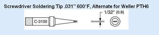
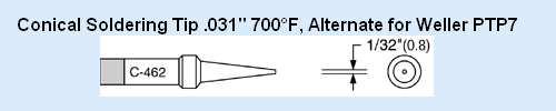
9 Which end of this thing gets hot? - 2 Tip selection different types: point, blade, chisel bottom line: want to match geometry of surface area warmed by tip with geometry of surface area to be soldered conical (point) tip circular area screwdriver (blade) tip rectangular area chisel tip triangular region if the tip is too small, it is difficult to get enough heat transfer for the solder to flow if the tip is too large, the flow of solder cannot be contained in a small area


10 Name That Tip chisel bent chisel screwdriver (blade) conical (point)
11 Which end of this thing gets hot? - 3 Tip selection note that chisel and screwdriver tips can be very useful for: soldering groups of pins at once on surface-mount devices removing solder bridges among several pins at once Basic soldering technique if needed, apply flux with pen/brush (e.g., for fine-pitch surface-mount components) heat area with iron tip (2-3 seconds) apply solder and allow to flow remove heat and allow to cool
12 Using the Right Amount of Solder a) Minimal b) Optimal c) Excessive see
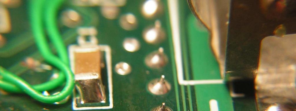
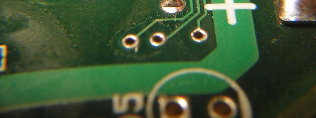
13 What s Wrong With These Pictures? see
14 What s Wrong With These Pictures? Bad soldering of terminal wire see
15 What s Wrong With These Pictures? Bad soldering of terminal wire Bad soldering of PCB pad see
16 What s Wrong With These Pictures? Bad soldering of terminal wire Bad soldering of PCB pad Bad soldering of both (solder did not flow properly) see
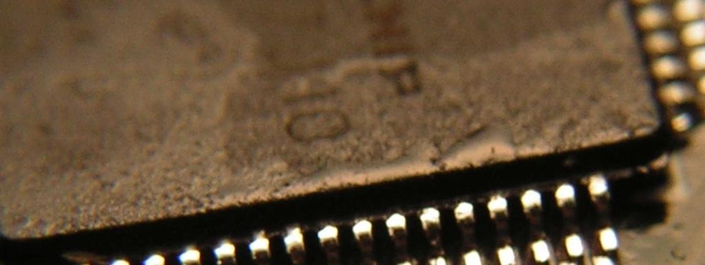
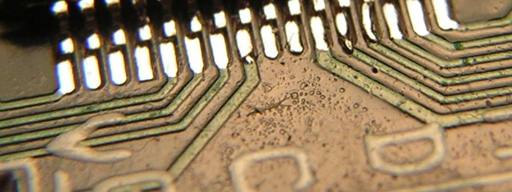
17 Which end of this thing gets hot? - 4 Solder removal (de-soldering) apply flux (if necessary) heat area to be de-soldered (surface-mount parts require a special heat gun to do this) use solder wick (copper braid) or solder sucker to remove solder Cautions cold solder joints (solder did not flow) too much heat (components will be damaged and/or traces will peel off board) access (be careful about assembly order!) examine solder joints of surface mount components using microscope
18 Flux is your friend. Flux is a liquid in which solder can flow Most electronic solder contains some flux Without flux, solder will be pasty and sticky (refuse to flow) The secret to soldering is using flux to make solder flow, and then controlling the heat so it flows under control
19 Static is your enemy. Many of the parts you will be using are static sensitive (can be damaged by ESD) To avoid damaging your components, do all of your board construction on the antistatic (blue/gray) mats in lab When soldering, use an anti-static wrist band and make sure it is connected to ground
20 Do unto your iron, as you would have it do unto you. Wet the sponge with distilled water before you begin Choose the iron with the appropriate tip for the job and set the temperature accordingly Tin and clean the tip before starting Clean the tip frequently during use Tin the tip when you are finished and TURN OFF the iron Use soldering irons only for soldering!
21
22
23
24
25 ECE 477 Module 11 Clicker Quiz
26 1. A soldering iron tip that can effectively be used to solder QFP surface mount packages is a: A. small screwdriver tip B. conical tip C. large chisel tip D. all of the above E. none of the above
27 2. A soldering iron tip that can effectively be used to solder axial lead components to circular (through-hole) pads is a: A. small screwdriver tip B. conical tip C. large chisel tip D. all of the above E. none of the above
28 3. A soldering iron tip that can effectively be used to solder surface mount resistors or capacitors is a: A. small screwdriver tip B. conical tip C. large chisel tip D. all of the above E. none of the above
29 4. Proper care of a soldering iron tip includes: A. removing oxidation with sandpaper or a file B. spraying the soldering tip with water C. constantly tinning the tip when the iron is on D. cleaning the tip in a solution of HKN coffee E. none of the above
30 5. Other potential uses for the soldering irons in lab include: A. warming HKN coffee B. boring holes in plastic C. engraving wooden plaques D. waking up sleeping teammates E. none of the above
Gat ew ay T o S pace AS EN / AS TR Class # 07. Colorado S pace Grant Consortium
 Gat ew ay T o S pace AS EN / AS TR 2500 Class # 07 Colorado S pace Grant Consortium One Minute Reports: - Can we have two data loggers? - Do you provide us with cameras? {Hardware Checkout after proposal}
Soldering & De-soldering
 Soldering and De-soldering Digital Electronics 04 Soldering & De-soldering This presentation will Review the tools needed to solder and de-solder electronic components. Demonstrate how to tin a soldering
SSRP LTC1746 Assembly Manual V0.1 Check the most recent version
 SSRP LTC1746 Assembly Manual V0.1 Check the most recent version http://oscar.dcarr.org/ssrp/hardware/ltc1746/ltc1746.php Introduction This manual details the general assembly process for the SSRP LTC1746
Soldering Techniques NIAGARA COLLEGE TECHNOLOGY DEPT.
 Soldering Techniques NIAGARA COLLEGE TECHNOLOGY DEPT. Soldering 101 Soldering is the process of joining two metals together to form an electrically ll and mechanically secure bond using heat and a third
Overview of Soldering Assessment Programs
 Overview of Soldering Assessment Programs 1 Objectives Provide a mechanism or program to evaluate the soldering and assembly skills of operators or applicants 2 Goals Provide Customer with the: Ability
Repairing your Porsche 928 Central Warning System (CWS) controller
 controller") Repairing your Porsche 928 Central Warning System (CWS) controller Disclaimer: This procedure is for a 1984 Porsche 928 S controller. Overview: Under the left foot pedal (dead pedal) of the Porsche 928
Repairing your Porsche 928 Central Warning System (CWS) controller Disclaimer: This procedure is for a 1984 Porsche 928 S controller. Overview: Under the left foot pedal (dead pedal) of the Porsche 928
ELECTRICAL CONNECTIONS
 ELECTRICAL CONNECTIONS Lesson 13 EET 150 Electrical Connections Learning Objectives In this lesson you will: see different methods of making electrical connections. learn a procedure for making soldered
Name My end of year 8 Target = Teacher. OLSJ Design & Technology Electronic Products. Overall Progress Effort Rating ABCDEFG.
 Name My end of year 8 Target = Teacher OLSJ Design & Technology Electronic Products Week 1 2 3 4 5 6 7 Lesson Objectives What will you learn about today? 1. Circuit Symbols and circuit diagram 2. Drilling
QUASAR ELECTRONICS KIT No DRILL SPEED CONTROLLER
 QUASAR ELECTRONICS KIT No. 1074 DRILL SPEED CONTROLLER General Description If you work with an electric drill and unless you are lucky enough to own one of the most sophisticated models with speed control,
Soldering and Desoldering Instruction
 Soldering and Desoldering Instruction Soldering is defined as "the joining of metals by a fusion of alloys which have relatively low melting points". In other words, you use a metal that has a low melting
GENERAL SOLDERING PROCEDURE
 College of Engineering Laboratory Procedure GENERAL SOLDERING PROCEDURE Dept: Multi-department Laboratory: Multi-lab Rm: Multi-lab Authored by: Dick Sevier, Lab Support Engineer Date: Reviewed and Approved
Tips in Soldering. By Jesus Beltran. Team J (AKA J Crew) EEC 134AB, Professor Xiaoguang Liu UC Davis College of Engineering
 EEC 134AB, Professor Xiaoguang Liu UC Davis College of Engineering") Tips in Soldering By Jesus Beltran Team J (AKA J Crew) EEC 134AB, 2015 16 Professor Xiaoguang Liu UC Davis College of Engineering INTRODUCTION Basic soldering skills is a trait that every electronic/electrical
Tips in Soldering By Jesus Beltran Team J (AKA J Crew) EEC 134AB, 2015 16 Professor Xiaoguang Liu UC Davis College of Engineering INTRODUCTION Basic soldering skills is a trait that every electronic/electrical
Technical Specifications - Characteristics
 Watt FM TRANSMITTER General Description This is a small but quite powerful FM transmitter having three RF stages incorporating an audio preamplifier for better modulation. t has an output power of 4 Watts
Cornerstone Electronics Technology and Robotics I Week 19 Soldering Tutorial
 Cornerstone Electronics Technology and Robotics I Week 19 Soldering Tutorial Administration: o Prayer o Turn in quiz o Using fixed resistors design and build a voltage divider divides 5 volts in half.
Tips For Soldering. By Harsh Tandel. Team Blip EEC 134A/B, Introduction
 Tips For Soldering By Harsh Tandel 914346151 Team Blip EEC 134A/B, 2017-2018 Introduction Every electrical engineer should at least know the basic soldering skills. It is very important to be familiar
Lighthouse Beginner s soldering kit
 Lighthouse Beginner s soldering kit Kit contains: 1 x 220 ohm resistor (Red, Red, Black) 1 x 82k ohm resistor (Grey, Red, Orange) 2 x 220k ohm resistors (Red, Red, Yellow) 2 x Diodes 1 x Power switch 1
SoftRock v5.0 Builder s Notes. December 12, Building a QSD Kit
 SoftRock v5.0 Builder s Notes December 12, 2005 Building a QSD Kit Be sure to use a grounded tip soldering iron in building the QSD board. The soldering iron needs to have a small tip, (0.05-0.1 inch diameter),
Installation tutorial for Console Customs Xbox ONE MaxFire ONE V2 PCB
 Installation tutorial for Console Customs Xbox ONE MaxFire ONE V2 PCB This tutorial is designed to aid you in installation of a console customs MaxFire ONE V2 Circuit board in the newer Xbox One Controllers
SOLDERING MANUAL A simple, yet easy to follow manual for your basic soldering needs. Copyright 2017 TortugaPro. All Rights Reserved
 A simple, yet easy to follow manual for your basic soldering needs Copyright 2017 TortugaPro. All Rights Reserved Purpose Soldering is not limited to electrical and electronics work. It is a skill that
Introduction to Soldering
 Introduction to Soldering The Soldering Iron American Standard Wire Gage (AWG) Solder The Soldering Process Stripping & Tinning Wire Connecting/Soldering Wire Component Soldering De-Soldering Lab Exercise
upad Proto Base Assembly Guide v2.0
 upad Proto Base Assembly Guide v2.0 Last Updated September 1, 2015 Table of Contents Preface... 3 Introduction... 3 Required Tools... 3 Flux Pen... 3 Soldering Iron... 3 Solder... 3 Diagonal Cutters...
Pacific Antenna Low Pass Filter Kit
 Pacific Antenna Low Pass Filter Kit Description Many basic transmitter and/or transceiver designs have minimal filtering on their output and frequently have significant harmonic content in their signals.
Solder Practice Kit MODEL AK-100. Elenco Electronics, Inc. Lesson Manual. Elenco Electronics, Inc.
 Solder Practice Kit MODEL AK-100 Elenco Electronics, Inc. 150 W. Carpenter Avenue Wheeling, IL 60090 (847) 541-3800 http://www.elenco.com e-mail: elenco@elenco.com Lesson Manual Elenco Electronics, Inc.
Pacific Antenna Easy SWR Indicator Kit
 Pacific Antenna Easy SWR Indicator Kit Description Monitoring the match of an antenna to your transmitter or adjusting an antenna tuner for best match requires an indicator of the reflected power as an
Explorer Wiring Kit (assembled)
") Explorer Wiring Kit (assembled) For Vintage, Firestorm & Standard Series Please Read All Instructions Before Beginning. Tools you will need: Soldering Iron (35 watt preferably) Solder Wet Sponge Wire Clippers
Explorer Wiring Kit (assembled) For Vintage, Firestorm & Standard Series Please Read All Instructions Before Beginning. Tools you will need: Soldering Iron (35 watt preferably) Solder Wet Sponge Wire Clippers
Introduction. Pictures in this lab have been taken from Pre-Lab Homework
 Introduction This lab relates to material in Hecht, Chapter 18. In this lab you will explore the concepts of circuits, resistors, and capacitors, by actually building a small circuit that is yours to keep!
Solder is a metallic glue that holds the parts together and forms a connection that allows electrical current to flow.
 Proper Soldering & Desoldering High Performance Ultrasonic Range Finders Techniques of a MaxBotix Sensor Materials Needed for Soldering Goggles Hands-free clamp Wire stripper Soldering iron with stand
FM Wireless Microphone Kit Instructions for Assembly Page 1 of 5
 Instructions for Assembly Page 1 of 5 1. Find Resistor R1. Remove any tape that may be attached to the leads. Bend the leads as needed to insert Resistor R1 into the printed circuit board in the holes
SoftRock v6.0 Builder s Notes. May 22, 2006
 SoftRock v6.0 Builder s Notes May 22, 2006 Be sure to use a grounded tip soldering iron in building the v6.0 SoftRock circuit board. The soldering iron needs to have a small tip, (0.05-0.1 inch diameter),
RAY S REWORK SECRETS TRAINING CERTIFICATION TEST (DVD-13C) v.3
 v.3") This test consists of twenty multiple-choice questions. All questions are from the video: Ray s Rework Secrets (DVD-13C). Each question has only one most correct answer. Circle the letter corresponding
This test consists of twenty multiple-choice questions. All questions are from the video: Ray s Rework Secrets (DVD-13C). Each question has only one most correct answer. Circle the letter corresponding
MEGAbitty Micro Line Sensor Board Assembly Instructions 11/15/2003
 1 Board Preparation U1 & U2 are mounted upside down, protruding through the board. That is, when the board is viewed from the top, the lenses should point down. Holes for U1 & U2 need to be cut out. Use
STEADY HAND GAME WITH LATCHING LED
 ESSENTIAL INFORMATION BUILD INSTRUCTIONS CHECKING YOUR PCB & FAULT-FINDING MECHANICAL DETAILS HOW THE KIT WORKS TEST YOUR HAND-EYE COORDINATION WITH THIS STEADY HAND GAME WITH LATCHING LED Version 2.0
Standard Kit #1 (3-way switch)
") Standard Kit #1 (3-way switch) Please Read All Instructions Before Beginning. Tools you will need: Soldering Iron (35 watt preferably) Solder Wet Sponge Wire Clippers 3/8 Drill Bit 1/4 Drill Bit Variable
Standard Kit #1 (3-way switch) Please Read All Instructions Before Beginning. Tools you will need: Soldering Iron (35 watt preferably) Solder Wet Sponge Wire Clippers 3/8 Drill Bit 1/4 Drill Bit Variable
How to solder SMD component on Awesome PCB or any other kind of PCB.
 How to solder SMD component on Awesome PCB or any other kind of PCB. Step by step tutorial, with no steps to skip. Step 1 - What do we need? Step 2 - Fixing PCB Step 3 - Preparing for soldering Step 4
Introduction. Circuit diagram
 Introduction You must have played with a dice at some time, for example when playing Ludo or Monopoly. Dice have existed for a very long time. The first known six-sided dice were found in Iraq and were
EE 1202 Labs: Ground Rules
 EE 1202 Labs: Ground Rules There are eight lab exercises that you will do as a part of EE 1202. The EE 1202 lab is ECSS 4.622, on the third floor of the ECSS building. Lab exercises will be done by teams
V6.2 SoftRock Lite Builder s Notes. November 17, 2006
 V6.2 SoftRock Lite Builder s Notes November 17, 2006 Be sure to use a grounded tip soldering iron in building the v6.2 SoftRock circuit board. The soldering iron needs to have a small tip, (0.05-0.1 inch
Ten Tec DDS Board Assembly Procedure
 05 May 2014 Ten Tec DDS Board Assembly Procedure You will find a photo of a completed board at the end of these instructions. Refer it whenever clarification is required. 1. AD9835 Attachment If you purchased
LP-200 Dummy Load / Wattmeter
 LP-200 Dummy Load / Wattmeter Enclosure Retrofit Assembly Instructions March 2009 TelePost Incorporated LP-200 is a trademark of TelePost Inc. Material in this document copyrighted 2009 TelePost Inc. 1
ECE 145A/218A, Lab Project #1a: passive Component Test.
 ECE 145A/218A, Lab Project #1a: passive Component Test. September 28, 2017 OVERVIEW... 2 GOALS:... 2 PRECAUTIONS TO AVOID INSTRUMENT DAMAGE... 2 SAFETY PRECAUTIONS... 2 READING:... 3 NETWORK ANALYZER CALIBRATION...
Pacific Antenna Field Strength Indicator Kit
 Pacific Antenna Field Strength Indicator Kit Description The Field Strength Indicator kit from Pacific Antenna provides a visual way to monitor the presence and relative strength RF fields through the
Easy Transmitter. Support ETX_REV5_Manual V2.7 Revised
 Easy Transmitter Introduction The Easy Transmitter kit from qrpkits.com provides a basic, crystal controlled transmitter with VXO tuning to provide a small tuning range around the crystal frequency. It
Read This Page First
 Read This Page First If you are reading this you know the manuals are always available at QRPKITS.com. This is version 8.0 of the manual dated 4/27/2016. There is no need to print out the whole assembly
Assembly Instructions for the 1.5 Watt Amplifier Kit
 Assembly Instructions for the 1.5 Watt Amplifier Kit 1.) All of the small parts are attached to a sheet of paper indicating both their value and id. 2.) Leave the parts affixed to the paper until you are
VC Divider Assembly manual
 1 VC Divider Assembly manual Thank you for your purchase of the SSSR Labs VC Divider DIY Kit! This manual will help you assemble the VC Divider quickly and easily. Follow the instructions! As you may know,
Soldering is easy. here's how to do it. Andie Nordgren (Comics adaptation) Jeff Keyzer. by: Mitch Altman (soldering wisdom) (Layout and editing)
 Jeff Keyzer. by: Mitch Altman (soldering wisdom) (Layout and editing)") Soldering is easy here's how to do it by: Mitch Altman (soldering wisdom) Andie Nordgren (Comics adaptation) Jeff Keyzer (Layout and editing) Download this comic book and share it with your friends! Distribute
Soldering is easy here's how to do it by: Mitch Altman (soldering wisdom) Andie Nordgren (Comics adaptation) Jeff Keyzer (Layout and editing) Download this comic book and share it with your friends! Distribute
Inspection Method Sheet
 Inspection Method Sheet Part Number: Generic Part Name: PCB Filters Drawing Number: Generic Operation: In Process / Final Page 1 of 10 Written By: Myra Cope Doc. #: TT-PC-0378 Rev. 14 Date: 10-15-08 Applicable
HAND SOLDERING FOR THROUGH-HOLE COMPONENTS (DVD-42C) TRAINING CERTIFICATION EXAM v.2
 TRAINING CERTIFICATION EXAM v.2") This test consists of thirty multiple-choice questions. All questions are from the video: Hand Soldering for Through-Hole Components (DVD-42C). Each question has only one most correct answer. Circle the
This test consists of thirty multiple-choice questions. All questions are from the video: Hand Soldering for Through-Hole Components (DVD-42C). Each question has only one most correct answer. Circle the
Better Soldering (A COOPER Tools Reprint) Overview Solder and Flux Base Material
 Overview Solder and Flux Base Material") Better Soldering (A COOPER Tools Reprint) Purpose We hope this short manual will help explain the basics of Soldering. The emphasis will be on the care and use of equipment. Overview Soldering is accomplished
Better Soldering (A COOPER Tools Reprint) Purpose We hope this short manual will help explain the basics of Soldering. The emphasis will be on the care and use of equipment. Overview Soldering is accomplished
QUAVERATO MIDI MOD. Assembly Instructions
 QUAVERATO MIDI MOD Assembly Instructions 110118 QUAVERATO MIDI MOD Assembly Instructions WHAT YOU WILL NEED...3 WHAT S IN THE BOX...4 POPULATING THE PRINTED CIRCUIT BOARD...7 THE CHASSIS...13 UPDATING
Soldering Basics. Purpose We hope this short manual will help explain the basics of Soldering. The emphasis will be on the care and use of equipment.
 Soldering Basics Purpose We hope this short manual will help explain the basics of Soldering. The emphasis will be on the care and use of equipment. Overview Soldering is accomplished by quickly heating
Experiment 2 Soldering Parallel and Series Circuits and using the Digital Multimeter
 Experiment 2 Soldering Parallel and Series Circuits and using the Digital Multimeter Introduction Soldering is the most common means of joining components to each other or to circuit boards in electronics.
Pacific Antenna Easy Transmitter Kit
 Pacific Antenna Easy Transmitter Kit Introduction The Easy Transmitter kit from qrpkits.com provides a crystal controlled transmitter with VXO tuning. The circuit consists of a N3904 based crystal oscillator
QUASAR PROJECT KIT # /24 HOUR GIANT CLOCK
 This project was originally published in the electronics magazine, Silicon Chip, a few years ago. It is issued here as a kit with permission. Some modifications to the original published circuit and software
SMT in Practice. Special Seminar III. Dr. Peter W. Pachowicz Department of Electrical and Computer Engineering Volgenau School of Engineering
 Special Seminar III SMT in Practice Dr. Peter W. Pachowicz Department of Electrical and Computer Engineering Volgenau School of Engineering This seminar is dedicated to students taking senior design project
Project 747 VERSION 1.3 USER MANUAL February 22nd 2018
 VERSION 1.3 USER MANUAL February 22nd 2018 WWW.GARAGE1217.COM WARNING: Project requires knowledge of AC electrical systems, repair of said systems and restoration of said systems. If proper safety measures
Bill of Materials: PWM Stepper Motor Driver PART NO
 PWM Stepper Motor Driver PART NO. 2183816 Control a stepper motor using this circuit and a servo PWM signal from an R/C controller, arduino, or microcontroller. Onboard circuitry limits winding current,
Ultrasound Range Finder
 Ultrasound Range Finder PCB Version 1.0 Assembly Manual Range Finder Assembly Instructions Read This Before You Begin 1. Avoid touching the PCB copper traces and pads with your fingers until you are ready
Assembly and User Guide
 Assembly and User Guide AtariPunkr is an adjustable stepped tone generator. AtariPunkr provides hours of fun everyone! Powered by: 9V Battery Outputs: Mylar Speaker (Included) Stereo Output (3.5mm Jack)
Turkey Football Panel
 Turkey Football Panel PROJECT TITLE: Turkey Football Turkey Football Panel A Stained Glass Project DESIGNED BY: Jeanne Baruth for Diamond Tech SKILL LEVEL: (Adult 1-5 1 being the easiest, 5 being difficult)
SOLDERING TO TRANSDUCERS
 APPLICATION NOTE AN-13 SOLDERING TO TRANSDUCERS The purpose of this Application Note is to aid the user of Knowles transducers to: Provide good electrical connections to the transducer Avoid undesired
LED Field Strength Indicator Kit
 LED Field Strength Indicator Kit Description The Field Strength Indicator kit from Qrpkits.com provides a visual way to monitor RF fields through the brightness of an LED. It will respond to RF fields
Any Questions? Contact us or Alligator Blinkie
 Alligator Blinkie The heart of this blinkie is a 12F1822 PIC produced by a company called Microchip. A PIC is a tiny, yet surprisingly powerful little computer. By itself, it can t do much it needs someway
by illumicon Morse ID generator Pietershoek XA Veldhoven The Netherlands fax
 by illumicon www.ezkits.eu Morse ID generator Pietershoek 3 5503XA Veldhoven The Netherlands fax +31-40-2230020 Contents Introduction...3 Soldering Tips...3 Assembly...4 Schematic...5 Connections...6 Configuration...7
Electrical Workshop. Module 6: Soldering Techniques. Academic Services Unit PREPARED BY. August 2012
 Electrical Workshop PREPARED BY Academic Services Unit August 2012 Applied Technology High Schools, 2012 Module Objectives Upon successful completion of this module, students should be able to: 1. Identify
LEARN TO SOLDER CLASS PACK
 TEACHING RESOURCES HOW TO SOLDER GUIDE BUILD INSTRUCIONS HOW THE KIT WORKS DEVELOP YOUR SOLDERING SKILLS WITH THIS LEARN TO SOLDER CLASS PACK Version 1.0 Index of Sheets Introduction... 3 Answers... 4
AR.Drone 2 - Main Board External Antenna Modification Procedure. Document Number: EAM Check back for updates.
 Document Number: EAM-20130303-2 Check back for updates. 3/22/2013 NOTE: Along with this mod procedure, you will also need to: 1. Remove the Main Board. Refer to the Main Board Removal Procedure 2. Adapt
SoftRock v6.0 Builder s Notes. April 6, 2006
 SoftRock v6.0 Builder s Notes April 6, 006 Be sure to use a grounded tip soldering iron in building the v6.0 SoftRock circuit board. The soldering iron needs to have a small tip, (0.05-0. inch diameter),
Installation tutorial for Console Customs PS3 TrueFire Standard Rapid fire Microchip for Sixaxis and Dualshock 3 controllers
 Installation tutorial for Console Customs PS3 TrueFire Standard Rapid fire Microchip for Sixaxis and Dualshock 3 controllers This tutorial is designed to aid you in installation of a console customs rapid
Circuit Board Assembly Instructions for Babuinobot 1.0
 Circuit Board Assembly Instructions for Babuinobot 1.0 Brett Nelson January 2010 1 Features Sensor4 input Sensor3 input Sensor2 input 5v power bus Sensor1 input Do not exceed 5v Ground power bus Programming
Modifying a USB sound fob to act as a repeater interface for app_rpt
 Modifying a USB sound fob to act as a repeater interface for app_rpt This document explains how to modify a USB sound fob to work as a repeater interface for app_rpt. The following materials and tools
Assembly instructions for the CS-1 ChemShield
 Page 1 Of 6 Assembly instructions for the CS-1 ChemShield What is S.M.D SMD=Surface mount devices, like all the components does not have leads, but gets soldered onto flat solder pads. The CS-1 assembly
Never power this piano with anything other than a standard 9V battery!
 Welcome to the exciting world of Digital Electronics! Who is this kit intended for? This kit is intended for anyone from ages 13 and above and assumes no previous knowledge in the field of hobby electronics.
Any Questions? Contact us or BSA Atomic Blinkie
 BSA Atomic Blinkie The heart of this blinkie is a tiny electronic chip embedded in each of the three LEDs. When power is applied, the chip tells the LED to turn on and off, or fade different colors By
Modification of USB Sound Card for Asterisk app_rpt Use
 Modification of USB Sound Card for Asterisk app_rpt Use First off a huge thank you to Steve for providing the original notes on how to modify a USB sound card. (http://images.qrvc.com/usbfob.pdf) These
ScaleRCHelis.com V Light Controller Kit
 Thank you for purchasing the ScaleRCHelis.com V1.1 450 Light Controller Kit. This is something you can build in under a hour with some simple soldering equipment. Your kit will include all the parts necessary
Standard Kit #1 (5-way switch)
") Standard Kit #1 (5-way switch) Please Read All Instructions Before Beginning. Tools you will need: Soldering Iron (35 watt preferably) Solder Wet Sponge Wire Clippers 3/8 Drill Bit 1/4 Drill Bit Variable
Standard Kit #1 (5-way switch) Please Read All Instructions Before Beginning. Tools you will need: Soldering Iron (35 watt preferably) Solder Wet Sponge Wire Clippers 3/8 Drill Bit 1/4 Drill Bit Variable
SOLDER PRACTICE KIT MODEL SP-3B. Assembly and Instruction Manual ELENCO
 SOLDER PRACTICE KIT MODEL SP-3B Assembly and Instruction Manual ELENCO Copyright 2017, 2001 by Elenco Electronics, Inc. All rights reserved. Revised 2012 REV-K No part of this book shall be reproduced
DEC-001 Installation Instructions
 DEC-001 Installation Instructions Skill Level: The installation of this assembly requires a medium level of expertise in working with modern electronic equipment. The use of appropriate tools, correct
Construction Hints and Techniques
 Construction Hints and Techniques You just get finished building a Microwave project and it looks beautiful. After admiring it for awhile you decide to spark it up. All of the voltages and currents look
Telecaster Wiring Kits Please Read All Instructions Before Beginning. Tools you will need: Soldering tips: Removing Current Wiring: Step 1. Step 2.
 Telecaster Wiring Kits Please Read All Instructions Before Beginning. Tools you will need: Soldering Iron (35 watt preferably) Solder Wet Sponge Wire Clippers Wire Strippers 3/8 Drill Bit 5/32 Drill Bit
Total solder points: 66 Difficulty level: beginner advanced. 15 Channel IR remote stick K8051 ILLUSTRATED ASSEMBLY MANUAL
 Total solder points: 66 Difficulty level: beginner 1 2 3 4 5 advanced 15 Channel IR remote stick K8051 Sleek designer enclosure with just 2 buttons, yet it provides acces to a stunning 15 channels. ILLUSTRATED
Assembly Instructions for the FRB FET FM 70 Watt Amp
 Assembly Instructions for the FRB FET FM 70 Watt Amp 1.) Orient the circuit board with the diagram 2.) Use a narrow chisel tip 25-30 watt soldering iron for assembly 3.) All the small parts are taped onto
PSU V2 for LawMate 500mW Transmitters. Assembly and Operation Manual
 PSU V2 for LawMate 500mW Transmitters Assembly and Operation Manual Introduction Thank you for purchasing the V2 LawMate 500mW Power Supply. This power supply was specifically designed for the 500mW LawMate
Soldering Application
 Soldering Application Eugene Kim EEC 134 Team GrildurFrostcrag!1 I. Introduction Soldering, using fusible metal alloy as an adhesive, played a key role in constructing the quarter two RF radars. It is
EET 150 Introduction to EET Lab Activity 6 Introduction to Wire Splicing and Soldering
 Required Parts, Software and Equipment Parts None for this activity EET 150 Equipment Required Hookup wire (22 AWG) Wire cutter/stripper Soldering Iron* Soldering Iron Stand* Solder (Use standard lead/tin
Data Sheet. Number: 003 Issue: BASIC SOLDERING TECHNIQUES.
 BASIC SOLDERING TECHNIQUES. You will need to practice. Nobody would buy a piano and expect to master the fundamentals immediately. So is it with soldering. The concept is simple. 1. Take two pieces of
Assembly and Installation Instructions for White Oak Audio Design TM-1001 LED board
 Thank you for purchasing White Oak Audio Design s TM-1001 Upgrade LED Light Board. White Oak Audio Design products are meticulously engineered and tested to ensure a direct drop in fit with your tuner.
5W Mono Amplifier Kit
 5W Mono Amplifier Kit Kit Construction Before you start assembling your kit there are a couple of important things you must do. FIRST read through these instructions entirely before you start construction
Learn to Solder: Simon Says Stencil Kit Information & Instructions
 Learn to Solder: Simon Says Stencil Kit Information & Instructions This is considered an intermediate kit for people who have soldered through-hole components before and wish to learn how to reflow surface
QRPme Crystal Checker Kit Featured in FDIM 2011 Build-Along
 QRPme Crystal Checker Kit Featured in FDIM 2011 Build-Along This crystal checker circuit was first presented in a workshop given by WA3OPY, AC5UR & W1REX a few years ago at the 4 States QRP Club gathering
Temperature activated switch
 Build instructions, circuit explanation and example applications Issue 1.5 Product information: www.kitronik.co.uk/quicklinks/2113/ TEACHER Temperature activated switch Introduction About the project kit
Pacific Antenna - Easy TR Switch
 Pacific Antenna - Easy TR Switch Kit Description The Easy TR Switch is an RF sensing switch that can be used to switch an antenna between a receiver and transmitter. It also has a second switched pair
DEM ABPM KIT All Band Power Meter Assembly Notes and Pictures
 DEM ABPM KIT All Band Power Meter Assembly Notes and Pictures Paul Wade W1GHZ w1ghz@arrl.net Down East Microwave has kindly agreed to make kits available for my All Band Power Meter (Note: I receive no
SOLDER PRACTICE KIT MODEL SP-3B. Assembly and Instruction Manual
 SOLDER PRACTICE KIT MODEL SP-3B 99 Washington Street Melrose, MA 02176 Phone 781-665-1400 Toll Free 1-800-517-8431 Visit us at www.testequipmentdepot.com Assembly and Instruction Manual Elenco Electronics,
AC/DC POWER SUPPLY KIT
 AC/DC POWER SUPPLY KIT MODEL K-11 Assembly and Instruction Manual ELENCO Copyright 2016, 1989 by ELENCO All rights reserved. Revised 2016 REV-O 753211 No part of this book shall be reproduced by any means;
SOLDER PRACTICE KIT MODEL SP-1A
 99 Washington Street Melrose, MA 02176 Phone 781-665-1400 Toll Free 1-800-517-8431 Visit us at www.testequipmentdepot.com SOLDER PRACTICE KIT MODEL SP-1A Assembly and Instruction Manual Elenco Electronics,
Gertboard Assembly Manual Rev 1.1
 Gertboard Assembly Manual Rev 1.1 The Gertboard is an add-on GPIO expansion board for the Raspberry Pi computer. It comes with a large variety of components, including buttons, LEDs, A/D converters, DACs,
Total solder points: 338 Difficulty level: beginner advanced. Remote control by telephone K6501 ILLUSTRATED ASSEMBLY MANUAL
 Total solder points: 338 Difficulty level: beginner 1 2 3 4 5 advanced Remote control by telephone K6501 Operate your appliances from anywhere with a simple phone call. ILLUSTRATED ASSEMBLY MANUAL H6501IP-1
Building the Toothpick Audio CW Filter
 Building the Toothpick Audio CW Filter Introduction The toothpick is a simple variable bandpass audio filter designed to compliment the Splinter QRPp Trans-Receiver. The filter also contains an audio amplifier