Inspecting a Barges Towing Rig
|
|
|
- Winfred Potter
- 6 years ago
- Views:
Transcription

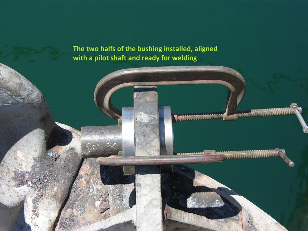
1 Inspecting a Barges Towing Rig Just about every tug boatman sooner or later gets a call from the office go pick up Barge X and tow it to Port B. Since we all work for ISM compliant companies and we follow our Safety Management System religiously we have all the records and certificates for our tug s towing gear aboard and up to date. But what about the tow gear on the barge we are going to tow? If the barge is one of your companies fleet there s a good chance that there will be records and certs for the gear. The likely hood is that these records will be incomplete or not up to date. If the barge has been overseas in a remote location for a number of years the towing gear may be worn out, incomplete or totally missing. Whichever the case, you as Master will need to inspect the tow gear or replacement gear as part of your tow plan. Where do you start? You start at the key grip areas. The grip areas are all those points of wear between the parts that make up the tow gear. Examples are: chain link to chain link; chain link to shackle; shackle to fish plate and barge towing pad to shackle. In the picture above you can see the wear in the grip point to the chain link.

2 Chain for bridles and surge gear Before rigging up for tow each bridle leg and length of surge gear should be walked and visually inspected for deformation, broken studs, and overall condition. At shipyard docking, a length in each leg over 5 links should be measured 3 times in every 15 fathom length under tension with a proper chain gauge. The inside reach and link length and width should also be checked within the 5 link samples. The diameter of the chain at the grip or crown of the link, for our range of sizes, has a minus tolerance of just 1/8"/3.175mm. The drawings and charts which follow should prove of interest in creating an informed perspective on chain rigging.
3 Damage to chain

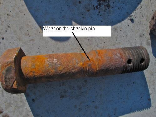
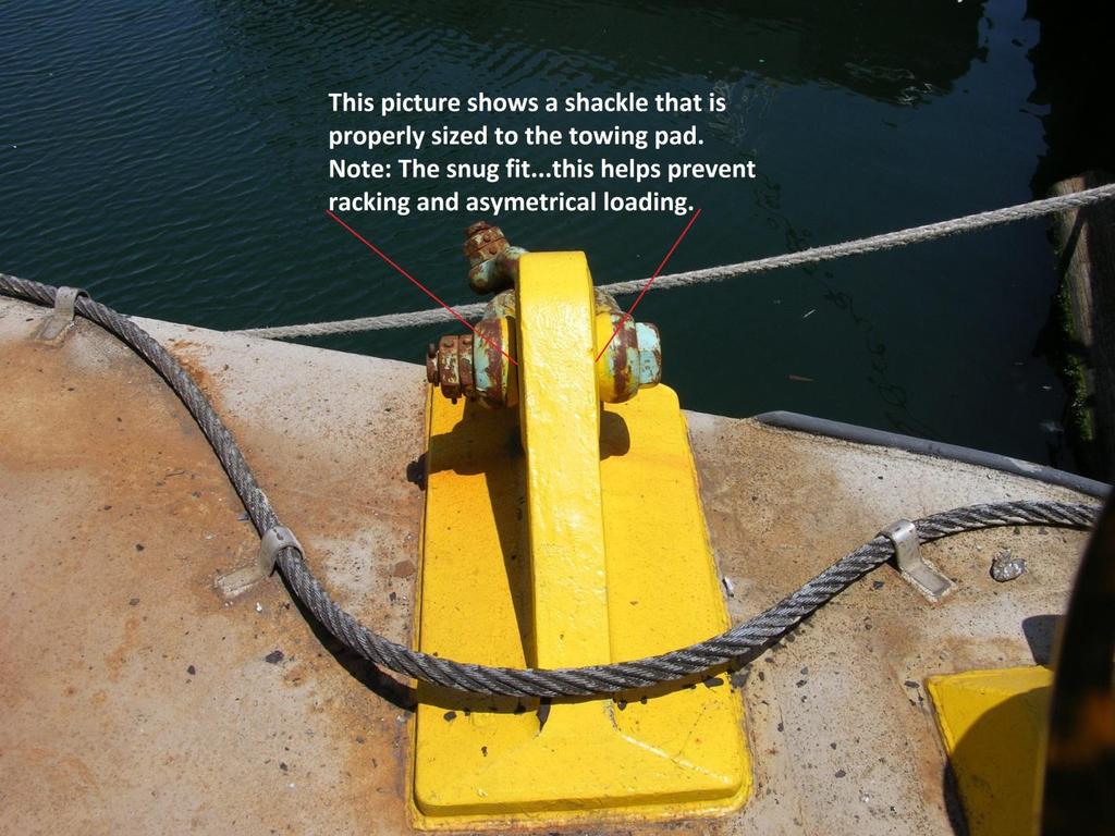
4 Towing Shackles In the field the diameter of the tow shackle pin, the diameter of the shackle bale and the condition of the pin as to straightness plus the fit and status of the threads and nuts are of particular importance.
5
6
7

8 A good chipping hammer can be invaluable when inspecting towing gear.

9 The fish plate and bridle connecting shackles have been hung off clear of the water over the barges head log. Hanging the gear off like this can greatly reduce the amount of wastage caused by electrolysis and oxidation. Plus you don t have to have all that mud and growth on the submerged chain hauled aboard.

10 Towing Plates As a practical matter, the flounder or towing plate can be visually inspected for cracks or fissures. Dimensionally it is to be checked at the shackle pockets and for elongation of the bore diameter at the under-rider or haul-in hole in accordance with the drawing. Heavy Duty Marquip towing
11 plates are issued to our vessels with a stamp indicating the plate has been dye checked, proof-tested and certified. Wear tolerance for H.D. #2 Flounder plates is 1 1/4" at the radius of each pocket.

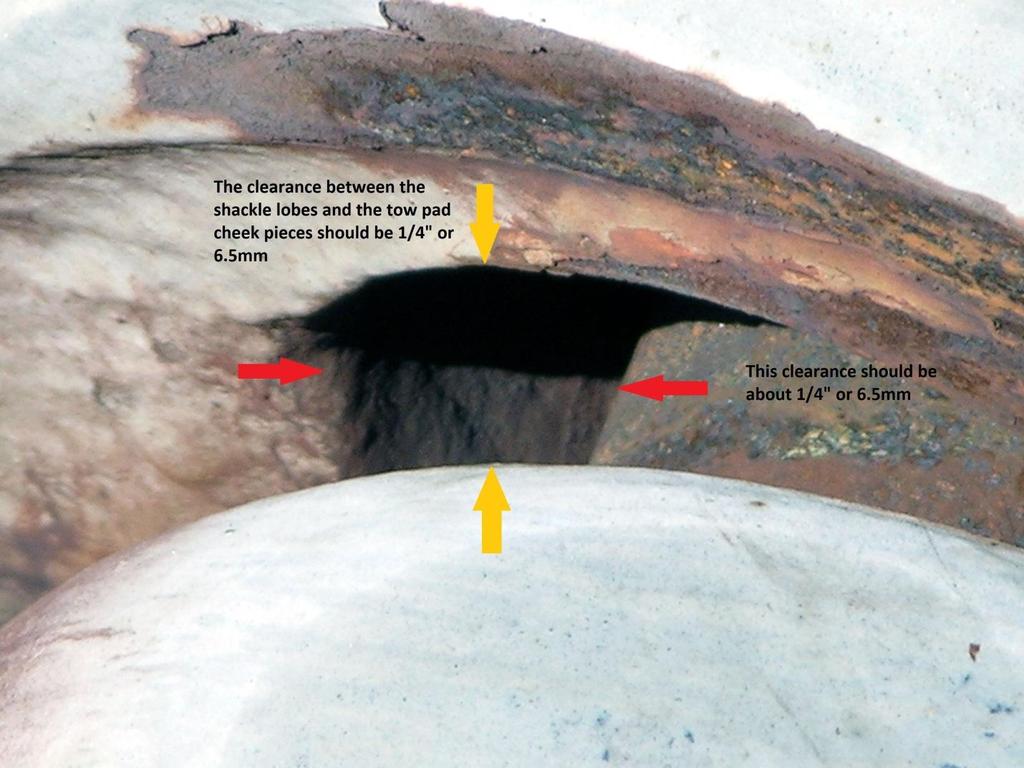
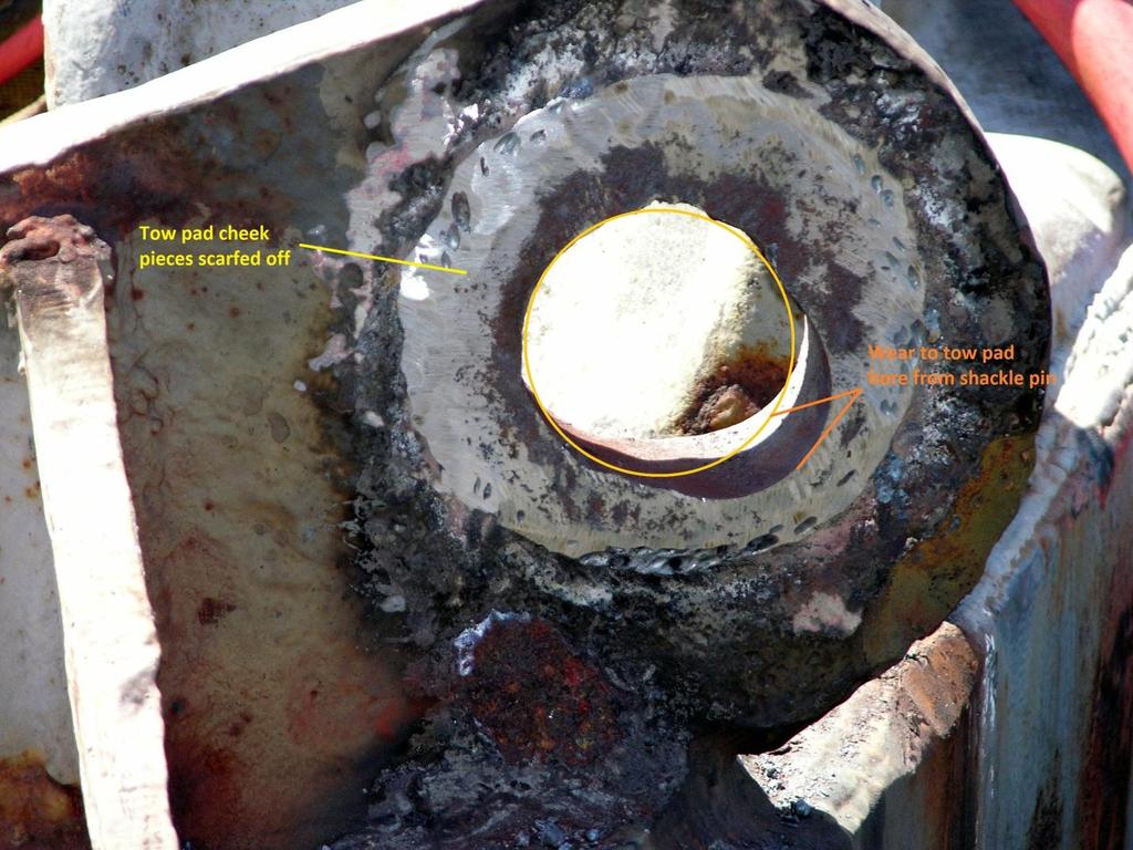
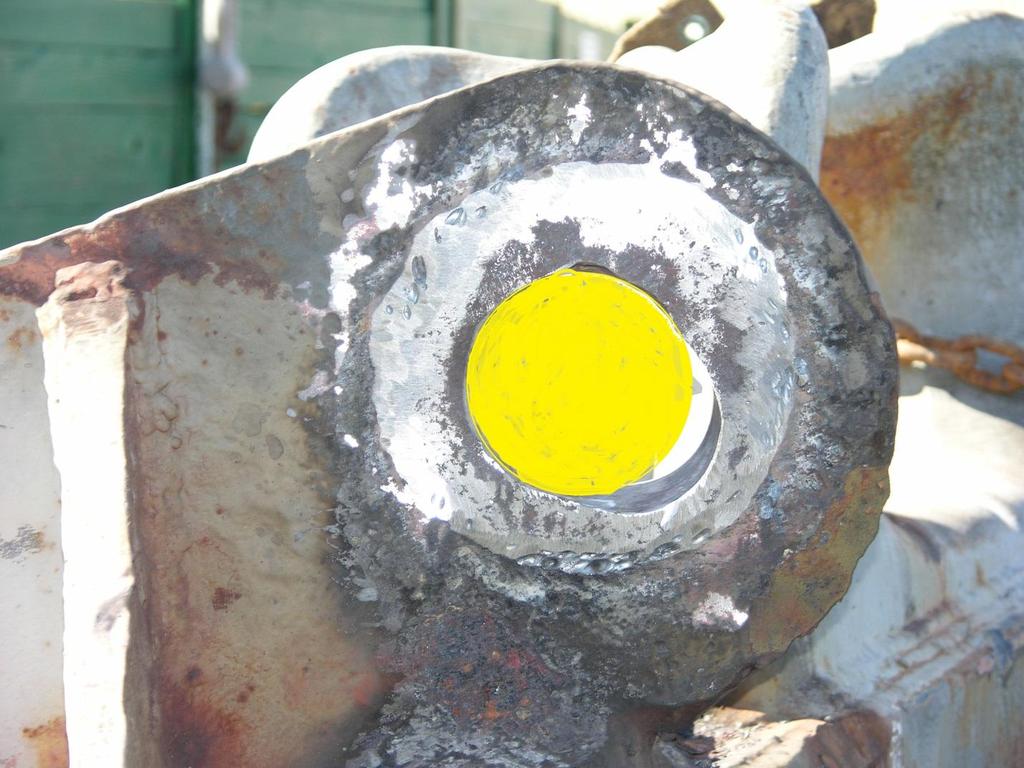
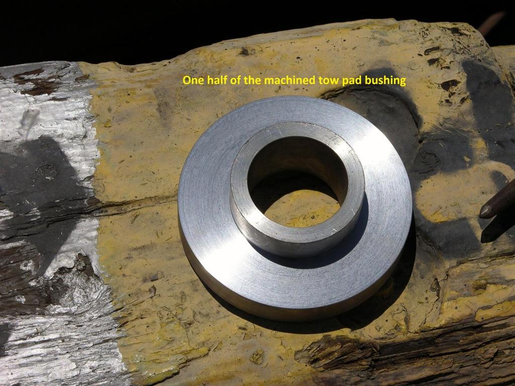
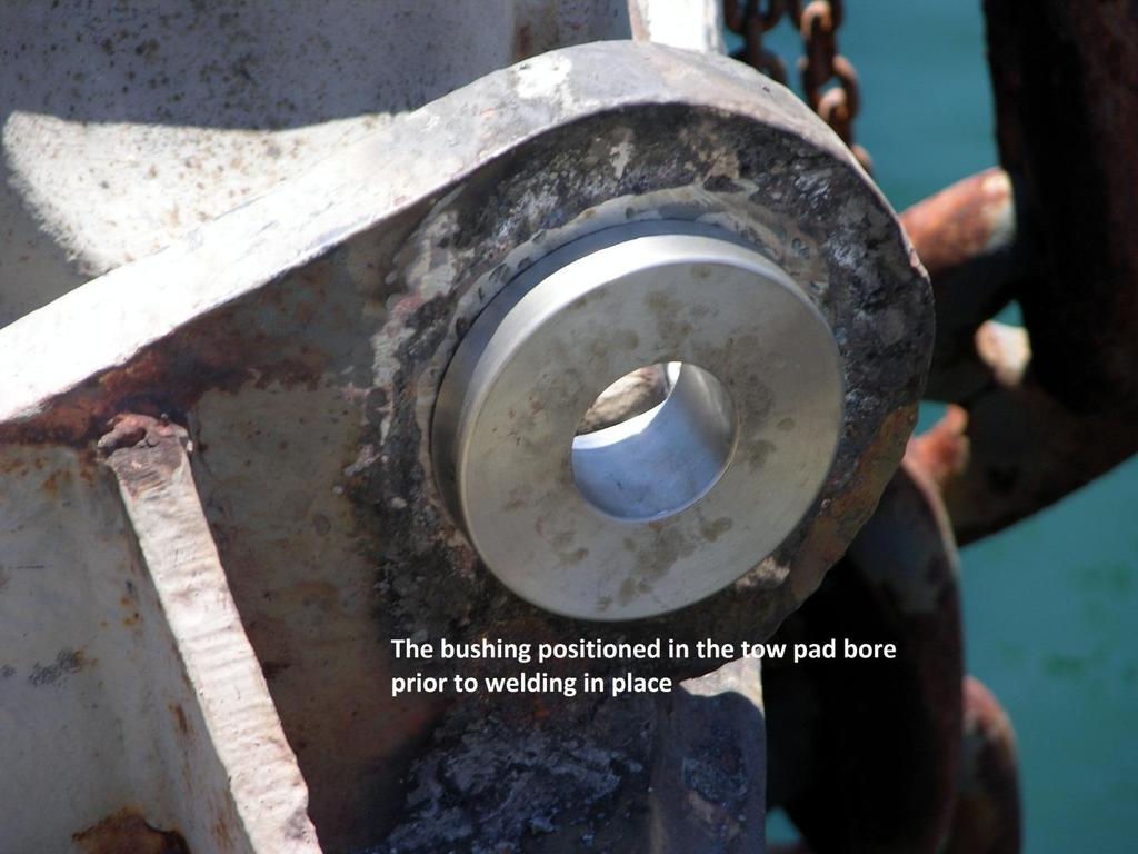
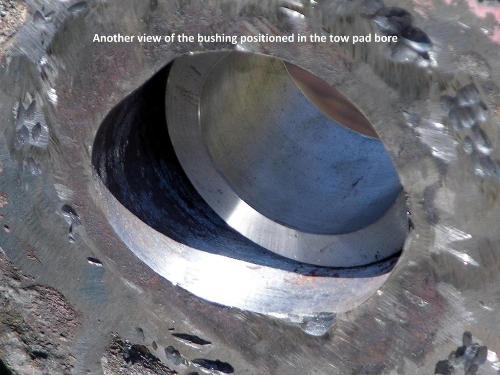
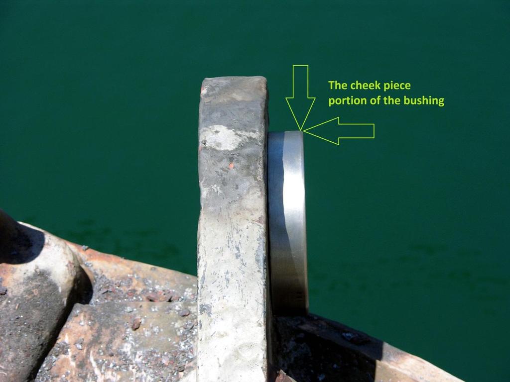
12 Towing Pad Eyes The Tow-Pad or Pad-Eye should be checked at the bore for elongation. Visually any evidence of body fissures or cracked welds in the mounting plate should be carefully assessed.
13
14
15
16
17
18
19
20
21

22
23 Emergency Tow Wire The Emergency Tow Wire should be visually inspected before getting underway. Although it is obviously not a working hawser and receives a thorough inspection on bi-annual dry-docking of the barge (including proof-testing of oil barge rigged wires and re-certification at an approved site), it is important to make sure the Emergency Tow Wire has not been damaged by a cargo loading mishap. The general condition of the sockets, butt-chain, haul-off wire, and float line should also be noted. The towing shackles and pad-eye made up forward should also be inspected according to the stated procedures for the main tow wire. The description which follows of the Emergency Tow Wire Rig and accompanying sketch reveal the detailed aspects of this assembly. tow-wire but also the condition of the haul-off wire, bill-board, make-up shackles and, in particular, the polypropylene float line. The weaker, smaller components must be up to their design strength and properly secured if they are to function until the Emergency Tow-Wire itself is bent to a towing shackle and re-serviced hawser. The emergency tow wire is rigged from a stout pad eye welded down on the centerline and well forward on the bow of a Foss barge. The rigging scheme begins with two tested tow shackles: the first is pinned at the pad eye and the second is pinned to the butt chain so that both these shackles are dressed bale to bale. From that second shackle about one quarter of a shot of appropriately sized chain (2 ¾-3 in/70-76mm the main) is led around the side of the barge where the selected emergency or insurance wire is made to the butt chain by dipping a third shackle through the socket. The secured emergency tow wire then runs down the full length of the barge where it comes around and along the after-rake where a fourth tested tow shackle is dipped through the socket at the end of the emergency wire and made up to a 200ft. length of 3/4" wire rope with a thimble eye per each end. This wire is secured, like the emergency tow wire itself, by means of smaller break-away
24 clips on a steel 'target-board' where this 3/4" haul-off wire is mounted in concentric circles. From a final thimble eye at the center of the billboard assembly a smaller 1-1/2 " galvanized shackle is made up to a 200 ft. length of 5"/127mm circumference spliced yellow polypropylene line which floats as it trails behind the towed barge.
25

26 Always check for missing gear

27 Emergency tow wire painted what is going on under the paint?

28
29
Installation Instructions for OPGW Bolted Dead End
 INS-ACA015 OPGW Bolted Dead End Procedure 1. Disassemble dead end. Remove one bolt from the same side of each keeper. Loosen other bolts to permit conductor to be placed in the conductor groove. If keepers
Requirement for Holes - Holes for Hanging
 Requirement for Holes - Holes for Hanging In order for items to progress through the series of pretreatment and galvanizing baths at our facility, they must be suspended in a suitable manner to ensure
Swivel Hoist Ring RIGGING ACCESSORIES. Color coded to distinguish between UNC (Red) and Metric (Silver) thread types.
 and Metric (Silver) thread types.") RIGGING ACCESSORIES Color coded to distinguish between UNC (Red) and Metric (Silver) thread types. Available in UNC and Metric thread sizes. UNC threads available in sizes from 800 pounds to 100,000 pounds,
RIGGING ACCESSORIES Color coded to distinguish between UNC (Red) and Metric (Silver) thread types. Available in UNC and Metric thread sizes. UNC threads available in sizes from 800 pounds to 100,000 pounds,
Swivel Hoist Ring Page 142
 Swivel Hoist Ring Page 142 Hoist Rings Color coded to distinguish between UNC (Red) and Metric (Silver) thread types HR-125 M HR-125 Available in UNC and Metric thread sizes. UNC threads available in sizes
Hex Head Bolt Set N - Includes lock nut. Used to connect male and female T connectors. Galvanized. 3/4" x 3-1/2". Standard Grade (f) Part #24279
 Part #24279") a Standard Grade (3/16 ) and Commercial Grade(1/4 ) Tie Down Is designed for use with 1-1/2" thick lumber (minimum width 6"). All hardware is mounted with 3/8" carriage bolts. All male and female dock
a Standard Grade (3/16 ) and Commercial Grade(1/4 ) Tie Down Is designed for use with 1-1/2" thick lumber (minimum width 6"). All hardware is mounted with 3/8" carriage bolts. All male and female dock
INSPECTION AND REMOVAL CRITERIA
 INSPECTION AND REMOVAL CRITERIA ASME B30.9-1 ALLOY STEEL CHAIN SLINGS 9-1.9.5 Removal Criteria Missing or illegible sling identification. Cracks or breaks. Excessive wear, nicks, or gouges. Stretched chain
DYNATRAC BALL JOINT REBUILD INSTRUCTIONS V5.0
 DYNATRAC PRODUCTS 2007-2018 JEEP JK HEAVY DUTY BALL JOINT JP44-2X3050-C DYNATRAC BALL JOINT REBUILD INSTRUCTIONS V5.0 WARNING: Improper use or installation of this product can cause major failures that
C-Clamps and Lifting Eyes (Eye Bolts)
") 0-C-Clamps & Lifting Eyes-R 2/21/08 9:42 PM Page 1 C-Clamps A B C Armstrong C-Clamps When your requirements call for clamps, specify Armstrong the most accepted name in the business. When you see Armstrong
0-C-Clamps & Lifting Eyes-R 2/21/08 9:42 PM Page 1 C-Clamps A B C Armstrong C-Clamps When your requirements call for clamps, specify Armstrong the most accepted name in the business. When you see Armstrong
Down Stage Right -Theatrical and Entertainment Rigging Supplies
 Shackle Plates There are five uniquely different designs in the Shackle Plates Dynasty. Each one allows you the freedom of choice as you design the rigging requirements of your scenery, as well as meeting
DYNATRAC BALL JOINT REBUILD INSTRUCTIONS V4.0
 DYNATRAC PRODUCTS 2007-2016 4X4 JEEP JK HEAVY DUTY BALL JOINT JP44-2X3050-C DYNATRAC BALL JOINT REBUILD INSTRUCTIONS V4.0 WARNING: Improper use or installation of this product can cause major failures
PROSTEER BALL JOINT REBUILD INSTRUCTIONS V1.0
 DYNATRAC PRODUCTS 2003-2010 4X4 DODGE 2500/3500 HEAVY DUTY BALL JOINT PROSTEER BALL JOINT REBUILD INSTRUCTIONS V1.0 WARNING: Improper use or installation of this product can cause major failures that could
Thank you for purchasing our product! *Please read these instructions and follow them step by step.*
 07/07/08.rev1 PAGE 1 OF 11 601AL VERTICAL 60120VL LIFT W/CHAIN DRIVE WINCH Thank you for purchasing our product! *Please read these instructions and follow them step by step.* Step 1. Separate and group
Requirements for manufacture of anchors
 W29 (June 2005) Requirements for manufacture of anchors 1. General requirements 1.1 Scope These Rules apply to the materials, manufacture and testing, and certification of anchors, shanks and anchor shackles
APPENDIX FENCE GENERAL NOTES
 APPENDIX FENCE GENERAL NOTES 1. Fabric: 9 gage, 2" mesh, knuckle top and bottom, placed on the outside of posts, single fabric width for the entire height. 2. All fencing to be standard galvanized finish.
Floating Lake Truss Dock Instructions
 Table of Contents Floating Lake Truss Dock Instructions 1. Dock Assembly and Set-Up 1.1 Installing Dock Floats 1.2 Positioning Quick Clips 1.3 Installing Anchor Posts 1.4 Installing Docks into the Water
Midwest Roadside Safety Facility
 B 64" 1626 602'-8 1/16" 183695 548'-0" 167030 1 2 3 4 5 6 7 8 9 10 11 12 14 15 16 17 18 20 21 22 23 24 25 26 27 28 29 30 31 32 33 34 35 36 373839 40 25 IMPACT 1500A 48" 12 27'-5" 8355 [] 3x7 CL A Galvanized
CAUTION INSTALLATION INSTRUCTIONS ! CAUTION. Heavy Duty Suspension Kits for Double Eye Springs. Safety Precautions: Inspection: Disassembly:
 INSTALLATION INSTRUCTIONS Heavy Duty Suspension Kits for Double Eye Springs K71-358-00 for Single Axles K71-359-00 for Tandem Axles with 33" Axle Spacing K71-360-00 for Triple Axles K71-448-00 for Tandem
Mathey Dearman Single and Double Screw Chain Clamp Parts & Operating Manual
 Machine Model Serial# WHERE THERE S PIPE, THERE S MATHEY Mathey Dearman Single and Double Screw Chain Clamp Parts & Operating Manual Revised: 1/9/2018 P. O. Box 472110, Tulsa, OK 74147-2110 USA Toll Free:
9/8/98 AC B CAUTION THE FOLLOWING TORQUE VALUES ARE DERIVED FROM OIL FREE CADMIUM PLATED THREADS.
 TABLE 7-1. Recommended torque values (inch-pounds). CAUTION THE FOLLOWING TORQUE VALUES ARE DERIVED FROM OIL FREE CADMIUM PLATED THREADS. TORQUE LIMITS RECOMMENDED FOR INSTAL- LATION (BOLTS LOADED PRIMARILY
H HD Adult Wheelchair Swing Frame & Hangers(perm) IMPORTANT
 IMPORTANT") Page 1 IMPORTANT PLEASE READ THESE INSTRUCTIONS BEFORE COMMENCING ASSEMBLY. All equipment must be installed in accordance with these instructions. Check your shipment against Bill of Lading and Parts list.
Page 1 IMPORTANT PLEASE READ THESE INSTRUCTIONS BEFORE COMMENCING ASSEMBLY. All equipment must be installed in accordance with these instructions. Check your shipment against Bill of Lading and Parts list.
Installation Manual Flat Track Series
 Manual Flat Track Series Contents Safety...1 Parts...2 Hardware.......................................... 2 Tools Required..................................... 4.............................................
5/16" Flange nut. Bolt Keeper Plate (8" Sq. SYS.) (3) 1/2" x 3" Hex head connector zinc plated bolt w/ washers and nut. Anchor 3" sq. 7 Ga.
 (3) 1/2 x 3 Hex head connector zinc plated bolt w/ washers and nut. Anchor 3 sq. 7 Ga.") 2 1/2" x 2 1/2" x 10 Ga. 6" 5" 4" Variable Slipbase (8" Sq. SYS.) 5/16 Corner Bolt W/ nut 5/16" Flange nut Stub Insert (8" Sq. SYS.) Bolt Keeper Plate (8" Sq. SYS.) (3) 1/2" x 3" Hex head connector zinc
2 1/2" x 2 1/2" x 10 Ga. 6" 5" 4" Variable Slipbase (8" Sq. SYS.) 5/16 Corner Bolt W/ nut 5/16" Flange nut Stub Insert (8" Sq. SYS.) Bolt Keeper Plate (8" Sq. SYS.) (3) 1/2" x 3" Hex head connector zinc
METAL-TO-METAL FASTENERS QUIKDRILL METAL2METAL METAL2METAL HD. Value through the Roof.
 METAL-TO-METAL FASTENERS QUIKDRILL METAL2METAL METAL2METAL HD Value through the Roof. Reliable Self-Drilling Performance. Superior Marco Value. Value drives everything we do. That s why our exclusive Weather-Tite
PRODUCT: LOKI INSTALLATION INSTRUCTIONS. Product is covered by U.S. patents. For more information visit
 R INSTALLATION INSTRUCTIONS PRODUCT: LOKI CONFIGURATION: SINGLE DOOR MOUNT: GLASS MOUNT Product is covered by U.S. patents. For more information visit www.krownlab.com . TOOLS + MATERIALS REQUIRED TOOLS
INSPECTION AND CORRECTION OF BELLHOUSING TO CRANKSHAFT ALIGNMENT
 INSPECTION AND CORRECTION OF BELLHOUSING TO CRANKSHAFT ALIGNMENT BACKGROUND Proper alignment of the transmission input shaft to the crankshaft centerline is required in order to achieve the best results
PRODUCT: BALDUR + ODEN
 R INSTALLATION INSTRUCTIONS PRODUCT: BALDUR + ODEN CONFIGURATION: SINGLE DOOR MOUNT: GLASS MOUNT Product is covered by U.S. patents. For more information visit www.krownlab.com . TOOLS + MATERIALS REQUIRED
Crimping Dies for TERMINYL* and PLASTI-GRIP* Terminals and Splices
 Crimping Dies for TERMINYL* and PLASTI-GRIP* Terminals and Splices Instruction Sheet 408-10051 11 APR 17 Rev D PROPER USE GUIDELINES Cumulative Trauma Disorders can result from the prolonged use of manually
BOTHWELL ALUMINUM PLANK AND DECK SYSTEM USERS MANUAL AND GUIDELINES
 BOTHWELL ALUMINUM PLANK AND DECK SYSTEM USERS MANUAL AND GUIDELINES 2015 TABLE OF CONTENTS 3 Introduction 4 General Use of Product 5 Use of Float Bars 4 Visual Inspection 5 Product List 6 Installing Float
Air Tractor, Inc. Repairs Page 5-i AT-802/802A July 30, 2008
 Repairs Page 5-i TABLE OF CONTENTS SECTION 5- REPAIRS No. Page FUSELAGE FRAME REPAIRS... 5-1 FORWARD CLAMP BLOCK BOLT FAILURE..5-1 STANDARD STRUCTURAL REPAIR DRAWINGS...5-1 Repairs Page 5-1 April 12, 2010
Crimping Dies; PN thru 47825, 47915, and 47918
 Crimping Dies; PN 47820 thru 47825, 47915, and 47918 Instruction Sheet 408-1729 22 NOV 16 Rev K Crimping Dies; PN 47820 thru 47825, 47915, and 47918 (Typical) Crimping Die Wire Size Part Number Color Code
PowerLock. Installation Instructions. Attention Dealers: Please give this owners manual to the customer when the product is delivered.
 Serving the Truck & Trailer Industry Since 1944 FOR Attention Dealers: Please give this owners manual to the customer when the product is delivered. Call 800-535-9545 www.aeroindustries.com Indianapolis,
Wrenches. Wrenches. F o r P. r o f e. s s i o. n a l s. .. S i. n c e 1
 F o r P r o f e Klein s line of wrenches are forged from the finest steel and are designed to deliver great strength, and long working life. Regardless of the job type, Klein has a wrench that will help
Product design: Structural systems
 Product design: Structural systems Tension and compression The arch bridge and the aerial ropeway in the panels below were designed to resist specific loads and forces. The arch has to resist the load
Available in high-capacity. and assembled by hand for smooth operation. Durable chrome-plated finish. Heat-treated for long life.
 Klein s line of wrenches are forged from the finest steel and are designed to deliver great strength and long working life. Regardless of the job type, Klein has a wrench that will help the professional
INSTALLATION INSTRUCTIONS
 1 INSTALLATION INSTRUCTIONS Prior to Assembling and Installing: 1) Field Check and verify that all components of the structure required for installation are in place per the approved shop drawings. Report
SECTION 3. BOLTS. bolt is a standard AN-type or a special-purpose bolt, and sometimes include the manufacturer.
 9/8/98 AC 43.13-1B SECTION 3. BOLTS 7-34. GENERAL. Hardware is the term used to describe the various types of fasteners and small items used to assemble and repair aircraft structures and components. Only
INSTALLATION INSTRUCTIONS ROPE ASSEMBLIES FATZER AG WITH HYEND SOCKETS FOR FROM. Kai-J. Thiem (THK) Martin Bechtold (BEM)
 Martin Bechtold (BEM)") INSTALLATION INSTRUCTIONS FOR ROPE ASSEMBLIES WITH HYEND SOCKETS FROM FATZER AG Created Kai-J. Thiem (THK) Checked Martin Bechtold (BEM) Released Kai-J. Thiem (THK) Version 2.0 Date 30.08.2016 Proof of
INSTALLATION INSTRUCTIONS FOR ROPE ASSEMBLIES WITH HYEND SOCKETS FROM FATZER AG Created Kai-J. Thiem (THK) Checked Martin Bechtold (BEM) Released Kai-J. Thiem (THK) Version 2.0 Date 30.08.2016 Proof of
A socket contact support (supplied separately) must be installed onto the locator assembly.
 must be installed onto the locator assembly.") Figure 1 PRO CRIMPER III Hand Tool Assembly 1976444 1 consists of PRO CRIMPER III Hand Tool Frame 354940 1 and Die Assembly 1976444 2. The tool assembly is used to crimp the contacts listed in Figure 1.
Figure 1 PRO CRIMPER III Hand Tool Assembly 1976444 1 consists of PRO CRIMPER III Hand Tool Frame 354940 1 and Die Assembly 1976444 2. The tool assembly is used to crimp the contacts listed in Figure 1.
GURANTEED TECHNICAL PARTICULARS OF BACK CLAMP FOR LT CROSS ARM
 Technical Specification of Back Clamp for LT Cross Arm (MS) Back clamp for LT Cross Arm made out of 50 x 6mm MS Flat suitable for 8m X 300 Kg PSC poles. After fabrication the cross arm shall be painted
THE CASCADE & SLINGER FUNSLIDES
 THE CASCADE & SLINGER FUNSLIDES ASSEMBLY AND INSTALLATION INSTRUCTIONS * * C A U T I O N * * S.R. SMITH CASCADE TM & SLINGER TM FUNSLIDES TM ARE MANUFACTURED FOR INSTALLATION AND USE ON RESIDENTIAL INGROUND
Apprentice has demonstrated satisfactory skill in performing the following tasks in actual on-the-job situations using air-tugger.
 TASK: Set up and Operate an Air Tugger 101 AIR TUGGER CHECKLIST following tasks in actual on-the-job situations using air-tugger. Tugger Task 1. Mount tugger Company 2. Unwind wire rope from spool 3. Anchor
KEEP YOUR RESOURCE MOVING.
 LINER BOLTS KEEP YOUR RESOURCE MOVING. COLUMBUS McKINNON CORPORATION Leading the Industry Downtime in the grinding mill operation is caused by one of two things: regularly scheduled maintenance or unscheduled
Crimping Dies for SOLISTRAND* Terminals and Splices
 ORIGINAL INSTRUCTIONS Crimping Dies for SOLISTRAND* Terminals and Splices Instruction Sheet 408-8691 02 AUG 18 Rev H1 PROPER USE GUIDELINES Cumulative Trauma Disorders can result from the prolonged use
HD installation guide
 JANUS INTERNATIONAL 1 866 562 2580 www.janusintl.c o m 1950 1950HD installation guide RIGHT DRIVE END SHOWN LH OPPOSITE LEFT TENSION END SHOWN RH OPPOSITE PUSH-UP OPERATION 1950 1950HD SHOWN A rolling
SAFETY THIS PRODUCT IS FOR OFFROAD USE ONLY. ALL LIABILITY FOR INSTALLATION AND USE RESTS WITH THE OWNER.
 SAFETY Your safety and the safety of others is very important. In order to help you make informed decisions about safety, we have provided installation instructions and other information. These instructions
PO STYLE AIR CLUTCH INSTALLATION AND MAINTENANCE MANUAL
 PO STYLE AIR CLUTCH INSTALLATION AND MAINTENANCE MANUAL P.O. Box 8148 Wichita Falls, Texas 76307 1600 Fisher Rd. Wichita Falls, Texas 76305 Phone: (940) 761-1971 Fax: (940) 761-1989 www.wptpower.com email:
SAFETY THIS PRODUCT IS FOR OFFROAD USE ONLY. ALL LIABILITY FOR INSTALLATION AND USE RESTS WITH THE OWNER.
 SAFETY Your safety and the safety of others is very important. In order to help you make informed decisions about safety, we have provided installation instructions and other information. These instructions
Assembly Instructions
 page 1 Serious personal-injury to the operator or bystanders, as well as damage to equipment or property, can occur, if all safety and assembly instructions, provided with this product, are not followed.
1. TOOLS + MATERIALS REQUIRED
 R INSTALLATION INSTRUCTIONS PRODUCT: BALDUR + ODEN CONFIGURATION: BI-PARTING DOOR MOUNT: TOP MOUNT Product is covered by U.S. patents. For more information visit www.krownlab.com. TOOLS + MATERIALS REQUIRED
2. Sanding the Modules Sand the entire surface of each cyc module with 60-grit sandpaper. This will provide for better paint adhesion.
 ASSEMBLY INSTRUCTIONS SYSTEM 4 BI (Built-In) Congratulations on your decision to use the world s most advanced and user-friendly cyclorama system. We have taken a great deal of care to create and ship
Disclaimer. Socket Products Socket depth limits maximum torque. Torque figures are based on 80% of maximum torque for a given key size.
 E546 V3 (1/17) Disclaimer Torque values listed in this book are based on mathematical calculations and experimental data. The values are valid only when the matched strength system listed is used. The
THE ROGUE TM FUNSLIDE TM
 THE ROGUE TM FUNSLIDE TM ASSEMBLY AND INSTALLATION INSTRUCTIONS * * C A U T I O N * * S.R. SMITH ROGUE TM FUNSLIDES TM ARE MANUFACTURED FOR INSTALLATION AND USE ON RESIDENTIAL INGROUND POOLS ONLY. ROGUE
18000 HDL FOUR POST LIFT LB CAPACITY INSTALLATION AND OWNER'S MANUAL
 18000 HDL FOUR POST LIFT 18000 LB CAPACITY INSTALLATION AND OWNER'S MANUAL WARNING! Do not raise a vehicle unless the front stops are in place, the parking brake is set, and the wheels are chocked. Stay
767, 777, DC-10, L-1011, MD-11 Tow Bar Equipment Manual
 514 MECKLEM LANE, ELLWOOD CITY, PENNSYLVANIA 16117 www.hallindustries.com E-mail: service@hallindustries.com 767, 777, DC-10, L-1011, MD-11 Tow Bar Equipment Manual Use This Manual for 1. Operating Procedures
400A 40113V, 401A 40120V, & 401AL 40120VL ALUMINUM VERTICAL 4000 LB LIFT INCLUDES SCREW LEG ASSEMBLY INSTRUCTIONS
 12/11/07 PAGE 1 OF 12 400A 40113V, 401A 40120V, & 401AL 40120VL ALUMINUM VERTICAL 4000 LB LIFT INCLUDES SCREW LEG ASSEMBLY INSTRUCTIONS Thank you for purchasing our product! *Please read these instructions
Inspec on Program Summary
 Inspec on Program Summary Inspec on program includes: Inspec on program includes: Wire Rope Wire Rope Slings Synthe c Web and Rigging Hardware Below-the-Hook Li ing Devices Custom Devices when applicable
Chain, Rope & Accessories
 A Perry Product Guide A range of both steel and plastic chain, including accessories. This range includes:- Steel Chain Plastic Chain Security Chain Accessories for Plastic Chain Accessories for Steel
Tech Unit No: Approved By: Quality Engineer Date: Lock-Set Packer
 Tech Unit No: 0802340000 Revision: A Approved By: Quality Engineer Date: 11-5-2014 Lock-Set Packer Description: The MAP Model Lock-Set Retrievable Casing Packer is a general purpose packer for production,
Operating Instructions and Parts Manual Lever Operated Chain Hoist JLH Series
 Operating Instructions and Parts Manual Lever Operated Chain Hoist JLH Series 1 Ton model shown JET 427 New Sanford Road LaVergne, Tennessee 37086 Part No. M-275050 Ph.: 800-274-6848 Revision H3 07/2018
DRIVE COMPONENTS REMOVAL. 9. FXCW/C: see Figure Remove bolt (9), sprocket retainer (8), and thrust washer (7). NOTE PRIMARY DRIVE LOCKING TOOL
, sprocket retainer (8), and thrust washer (7). NOTE PRIMARY DRIVE LOCKING TOOL") DRIVE COMPONENTS REMOVAL PART NUMBER HD-7977 TOOL NAME PRIMARY DRIVE LOCKING TOOL S To remove the primary chain, remove compensating sprocket, clutch assembly and primary chain as an assembly:. Remove
DRIVE COMPONENTS REMOVAL PART NUMBER HD-7977 TOOL NAME PRIMARY DRIVE LOCKING TOOL S To remove the primary chain, remove compensating sprocket, clutch assembly and primary chain as an assembly:. Remove
CAUTION INSTALLATION INSTRUCTIONS ! CAUTION. E-Z Flex Suspension Kits for Double Eye Springs. Safety Precautions: Inspection: Disassembly:
 INSTALLATION INSTRUCTIONS E-Z Flex Suspension Kits for Double Eye Springs K71-652-00 E-Z Flex Complete Kit for Tandem Axles with 33" Axle Spacing, 6000 Lb. Max Capacity K71-653-00 E-Z Flex Complete Kit
Terminals and Splices 19 OCT 11 Rev D. Crimping Dies for Head Numbers 69065, 69067, and Hand Tool Yoke. Place Screwdriver Here to Remove Dies
 Instruction Sheet Crimping Dies for SOLISTRAND* 408-9786 Terminals and Splices 19 OCT 11 PROPER USE GUIDELINES Cumulative Trauma Disorders can result from the prolonged use of manually powered hand tools.
PowerLock. Installation Instructions. Attention Dealers: Please give this owners manual to the customer when the product is delivered.
 Serving the Truck & Trailer Industry Since 1944 PowerLock Attention Dealers: Please give this owners manual to the customer when the product is delivered. Call 800-535-9545 www.aeroindustries.com Indianapolis,
PAGE 12 : THREAD MEASUREMENT TECHNIQUE (Plated and unplated thread gauges)
") 40-60 Delaware St. MACHINING Part No. PR301 - INDEX- MACHINING SECTION Revision: 01/12/2012 PAGE 1 This Quality Standard applies to all metallic parts unless otherwise specified by drawing or specification.
40-60 Delaware St. MACHINING Part No. PR301 - INDEX- MACHINING SECTION Revision: 01/12/2012 PAGE 1 This Quality Standard applies to all metallic parts unless otherwise specified by drawing or specification.
Safety clamps, inc. Operation, Maintenance and Repair Manual for. Model HBC. Home of the big Bite Lifting Clamp
 Safety clamps, inc. Home of the big Bite Lifting Clamp Operation, Maintenance and Repair Manual for Model HBC Products manufactured by Safety Clamps, Inc. meet and/or exceed ANSI/ASME B30.20 standards
Tool 3-1 A2 Bushing 6 Check if the bushing supports (angle iron) are properly welded with the upper part of the structure pipes. welded bushing suppor
 are properly welded with the upper part of the structure pipes. welded bushing suppor") Rope Pump MANUFACTURING checklist for quality control A Welding General 1 Check if welding jigs are used for welding of the main parts (wheel, structure frame and bushings) 2 Check if the pump parts are
Rope Pump MANUFACTURING checklist for quality control A Welding General 1 Check if welding jigs are used for welding of the main parts (wheel, structure frame and bushings) 2 Check if the pump parts are
18 GAUGE ELECTRIC METAL SHEAR
 241-9895 18 GAUGE ELECTRIC METAL SHEAR Operator s Manual SAVE THIS MANUAL You will need this manual for safety instructions, operating procedures and warranty. Put it and the original sales receipt in
DRAFT TANZANIA STANDARD MEDC 10(5692) P3 - SPECIFICATION FOR HONEY EXTRACTOR, RADIAL TYPE
 P3 - SPECIFICATION FOR HONEY EXTRACTOR, RADIAL TYPE") DRAFT TANZANIA STANDARD MEDC 10(5692) P3 - SPECIFICATION FOR HONEY EXTRACTOR, RADIAL TYPE TBS 2018 Draft Edition 1 0. FOREWORDS Honey extractors enable bee-keepers to extract the maximum quantity of honey
DRAFT TANZANIA STANDARD MEDC 10(5692) P3 - SPECIFICATION FOR HONEY EXTRACTOR, RADIAL TYPE TBS 2018 Draft Edition 1 0. FOREWORDS Honey extractors enable bee-keepers to extract the maximum quantity of honey
PREVIEW COPY. Table of Contents. Lathe Setup and Workpiece Preparation...3. Lesson Two Rough Turning and Finish Turning...19
 Table of Contents Lesson One Lathe Setup and Workpiece Preparation...3 Lesson Two Rough Turning and Finish Turning...19 Lesson Three Lesson Four Boring and Counterboring...35 Cutting Internal Threads and
Hardened Structures Hardened Shelters, LLC. Explosion Resistant Pre-hung Sealed Blast Door
 Hardened Structures Hardened Shelters, LLC Explosion Resistant Pre-hung Sealed Blast Door Drawing number: ASR-50-BD Revision: E Date: December 8, 2008 Table of Contents Contact Information... 3 Description...
UNIT 9 TOOLS FOR BASIC LAYOUT
 UNIT 9 TOOLS FOR BASIC LAYOUT Tools for Basic Structure 9.1 Introduction Objectives 9.2 Tools for Scribing 9.3 Accessories 9.4 Summary 9.5 Key Words 9.1 INTRODUCTION The process of making reference mark
Ford Pick Up Rear leaf Spring Kit Installation Instructions
 1948-1956 Ford Pick Up Rear leaf Spring Kit Installation Instructions 1-800-984-6259 www.totalcostinvolved.com Parts 48 inch leaf (2) springs (4) U-bolts 3/8-24 x l 1/4bolts (16) & nuts (2) 1/2-20 x 4
METAL FABRICATION SECTION 8: METAL FABRICATION SCOPE MATERIAL.
 METAL FABRICATION SCOPE This specification applies to all metal intended to be rubber lined. Metals furnished must conform to this specification with respect to suitability for rubber lining or covering.
Construction Instructions for Continental and Quickfit Clearspan Frame Marquees
 Construction Instructions for Continental and Quickfit Clearspan Frame Marquees ERECTION INSTRUCTIONS - CONTINENTAL & QUICKFIT FRAME TENTS CONTINENTAL & QUICKFIT FRAME TENTS A system of clearspan frame
Transmission Line Support Systems
 Antenna Support Bracket for transmission line The Antenna Support Bracket angle mounts directly to a 4-1/2" (114 mm) OD antenna pipe mount or tower leg. This is ideal for supporting transmission line runs
flex Installation multiflex
 flex Installation Manual12m multiflex Table of Contents Page# Bolts........................................................................ 3 General Information.........................................................
TIN KNOCKER TK 1660 DUCT BEADER
 TIN KNOCKER TK 660 DUCT BEADER Sheet Metal Equipment Sales Inc. Dean P. O'Connell, President Green Bay, Wisconsin Phone - (90)-66-9966 Fax - (90)-66-9969 06/04/004 Website: www.sheetmetalequip.com TIN
PowerLock. Installation Instructions. Attention Dealers: Please give this owners manual to the customer when the product is delivered.
 Serving the Truck & Trailer Industry Since 1944 FOR Attention Dealers: Please give this owners manual to the customer when the product is delivered. Call 800-535-9545 www.aeroindustries.com Indianapolis,
1. Turn off or disconnect power to unit (machine). 2. Push IN the release bar on the quick change base plate. Locking latch will pivot downward.
. 2. Push IN the release bar on the quick change base plate. Locking latch will pivot downward.") Figure 1 Miniature Quick Change Applicators, of the end feed type, are designed to crimp end feed strip terminals to prestripped wires. Each applicator is set up to accept the strip form of certain specific
Figure 1 Miniature Quick Change Applicators, of the end feed type, are designed to crimp end feed strip terminals to prestripped wires. Each applicator is set up to accept the strip form of certain specific
Inventory (Figure 2)
") MODEL T24631 8" SPIRAL CUTTERHEAD Installation INSTRUCTIONS For questions or help with this product contact Tech Support at (570) 546-9663 or techsupport@grizzly.com Introduction The Model T24631 spiral
MODEL T24631 8" SPIRAL CUTTERHEAD Installation INSTRUCTIONS For questions or help with this product contact Tech Support at (570) 546-9663 or techsupport@grizzly.com Introduction The Model T24631 spiral
GE-Westinghouse-AO Smith Backend Gearbox Conversion Kit Installation Guide
 New products are developed and released throughout the year. Visit our website regularly pinsetterpartsplus.com GE-Westinghouse-AO Smith Backend Gearbox Conversion Kit Installation Guide New products are
Contents. Grade 2, 5, 8 Hex Bolts 4. Heavy Hex Head Structural Bolts 6. A325 and A490 Tension Control Bolts (TC) 13. Nuts 22.
 13. Nuts 22.") Who we are Amcan Jumax is the result of a merging between Boulons Jumax and Amcan Threaded Products, two successful companies well established, both with excellent reputations. The new entity is a bigger
Who we are Amcan Jumax is the result of a merging between Boulons Jumax and Amcan Threaded Products, two successful companies well established, both with excellent reputations. The new entity is a bigger
Fortress Fe Posts must always be secured to the deck framing. Fortress Fe Posts should never be attached to only the deck boards.
 Installation Instructions for FortressCable V-Series Cable Stair Panel System with UB-05 With ngle dapter and Fe Posts It is the responsibility of the installer to meet all code and safety requirements,
015 : 1993 CEB STANDARD
 015 : 1993 CEB STANDARD UNGALVANIZED STAY ASSEMBLIES CEYLON ELECTRICITY BOARD SRI LANKA Specification for UNGALVANIZED STAY ASSEMBLIES CEB Standard 015 : 1993 CEYLON ELECTRICITY BOARD No. 50, Sir Chittampalam
Trade of Metal Fabrication. Module 3: Plate Fabrication Unit 7: Sloping Chute Phase 2
 Trade of Metal Fabrication Module 3: Plate Fabrication Unit 7: Sloping Chute Phase 2 Table of Contents List of Figures... 5 List of Tables... 6 Document Release History... 7 Module 3 Plate Fabrication...
MODEL T " SPIRAL CUTTERHEAD INSTRUCTIONS
 MODEL T10125 6" SPIRAL CUTTERHEAD INSTRUCTIONS The Model T10125 spiral cutterhead is designed to replace the straight knife cutterhead on the Model G0452 6" jointer. The total procedure of changing the
SPECIFICATIONS FOR THE MANUFACTURE AND DESIGN OF PRECAST THREE SIDED ARCH STRUCTURES, WINGWALLS AND HEADWALLS
 SPECIFICATIONS FOR THE MANUFACTURE AND DESIGN OF PRECAST THREE SIDED ARCH STRUCTURES, WINGWALLS AND HEADWALLS 1. DESCRIPTION THESE SPECIFICATIONS ARE FOR A PRECAST THREE SIDED ARCH STRUCTURE, HEADWALLS
Complete line of Holemaking Products and Accessories
 Complete line of Holemaking Products and Accessories I N T R O D U C I N G Holemaking Products Klein Tools has expanded our line of Holemaking products. We have added new flexible drill bits and related
Riveted Joints : Types and Uses
 Riveted Joints : Types and Uses Page 1 / 10 Instructional Objectives: At the end of this lesson, the students should be able to know: Basic types of riveted joints. Different important design parameters
Block and Ball Inspection Checklist
 Block and Ball Inspection Checklist 01/16 P/N 67688 Rev. 1 Page 2 of 8 Block and Ball Inspection Checklist The purpose for the inspection check list is to provide a quick reference for checking the integrity
NINIGRET MARINE INC.
 NINIGRET MARINE INC. everything you need to make docks Suppliers of Dock Hardware Marine Construction Hardware Specialty Hardware Permafloats 3964 South County Trail (Route 2) Charlestown, RI 02813 Telephone
HOME GYM Owner s Manual
 HOME GYM Owner s Manual Content Content-------------------------------------------------------------1 Safety precautions----------------------------------------------------2 Assembly instruction-------------------------------------------------3-12
T R I - S TA N D C H A I N V I S E
 T R I - S TA N D C H A I N V I S E OWNER S MANUAL Item# 23235 WARNING: Read carefully and understand all ASSEMBLY AND OPERATION INSTRUCTIONS before operating. Failure to follow the safety rules and other
installation guide
 JANUS INTERNATIONAL 1 866 562 2580 w w w. j a n u s i n t l. c o m 2000 2500 3000 installation guide RIGHT DRIVE END SHOWN LH OPPOSITE LEFT TENSION END SHOWN RH OPPOSITE PUSH-UP OPERATION 2000 2500 3000
`48-`56 Ford Pickup Rear leaf Spring Kit Installation Instructions Tech Line:
 `48-`56 Ford Pickup Rear leaf Spring Kit Installation Instructions Tech Line: 1-855-693-1259 www.totalcostinvolved.com CHECK ALL PARTS INCLUDED IN THIS KIT TO THE PARTS LIST BEFORE INSTALLING THE KIT.
Steel Construction Tools
 F o r P Steel Construction Tools r o f e s s i o n a l s. Klein has combined unique design features with skillful engineering and manufacturing to create a superior line of steel construction tools. These
SLICKLINE WIRE AND WELL SERVICE STRAND MANAGEMENT
 SLICKLINE WIRE AND WELL SERVICE STRAND MANAGEMENT SUGGESTED GUIDANCE Slickline Management: 0.092 Diameter Slickline Proper management and care of slicklines will prolong working life of materials. Lines
 BHARAT HEAVY ELECTRICALS LIMITED TIRUCHIRAPALLI 620 014 QUALITY ASSURANCE SIP:NP:02 /02 PAGE : 1 Of 11 TRIAL ASSY OF COLUMNS, CEILING GIRDERS, MONORAIL & RUNWAY BEAMS REV. DATE PREPARED REVIEWED APPROVED
27APR18 U.S. RACK, Inc Falcon Drive, Madera, CA
 27APR18 U.S. RACK, Inc. - 2850 Falcon Drive, Madera, CA 93637-559-661-3050 INSTRUCTIONS for FIFTH WHEEL RACK Model 2010-4ADC WARNING: Do NOT attempt to install or use this rack without following all instructions.
Installation Instructions
 CHEVY / GMC 24K Industry Standard Rail Heavy Duty Custom Mounting Kit #2226 Gross Trailer Weight (Maximum)...24,000 lbs. Vertical Load Weight (Max. Pin Weight)...6,000 lbs. SYSTEM TOW CAPACITY Please note,