PART TWO $10 TNC CONSTRUCTION PROJECT AUDIO BOARD AND FINAL ASSEMBLY November, 2016
|
|
|
- Conrad Clarke
- 5 years ago
- Views:
Transcription

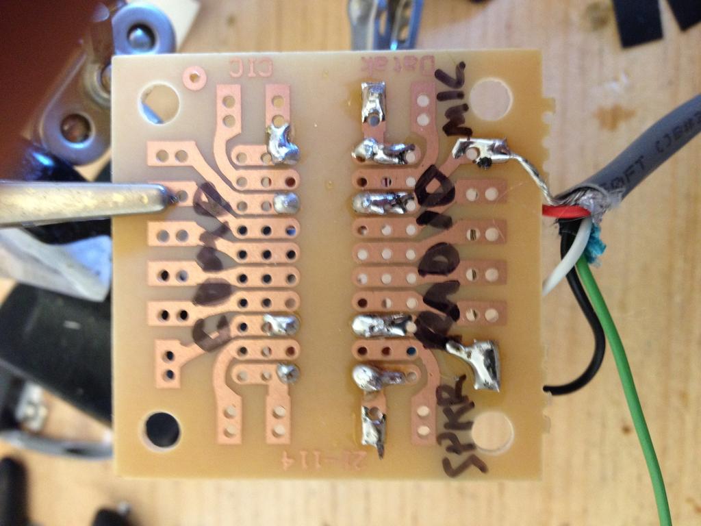
1 PART TWO $10 TNC CONSTRUCTION PROJECT AUDIO BOARD AND FINAL ASSEMBLY November, 2016 Mark the side of the board that will have connections to the RADIO, and the side that will have connections to the COMPUTER. Mark the underside also. Then mark the radio side that will go to the MIC of the radio (red wire) and the side that will come from the SPEAKER (although it is a white wire in this photo, that is an error -- should be the green wire) Solder in the transformers and the 0.01 microfarad capacitors and make the connections for the radio wires. The Push to Talk wire (white) will remain unused for now. Note the jumper to allow the ground wire to connect to both transformers. 1
2 2

3 This board layout actually isn't that good for these connections. The 3 pins of the trimmers won't fit because the board isn't drilled on 0.1 centers everywhere. I had to bend the center terminal of the trimmers UP and then I picked these positions for the trimmers to try and make the connections that needed to be made, possible. Be careful not to position the trimmers so that they actually connect to transformer leads that you didn't want them to connect to! 3


4 Note the resistors and the jumpers needed to make the required center tap and ground connections. 4

5 If you are going to use stereo plug/cables to make the connections to the USB dongle, you won't need this, but if you are going to crack it open and solder directly, here is the photo: In this photo, the orange wire going near the big white USB cable, is picking off +V from the tiny soldering connection available there. This is a difficult soldering job, be careful. As an alternative, you can use a second USB cable, just to get to the red and black wires (+v and ground, respectively). This is a lot easier to accomplish mechanically! The RED wire on the jack with only one connection, is the mic input wire. The green wire is the Left Channel headphone output (tip) The blue wire is the Right Channel headphone output (ring) The gray wire is the Ground (both DC and AC for the computer side) I recommend that you glue the circuit down in the bottom plate after this wiring is done properly. I used 5 minute epoxy and secured the usb wire in the process. 5

6 Wiring to the USB audio dongle: There are four signals you need to connect to.. Using tiny very flexible stranded wire will make this a lot easier. After you get all the connections done and have tested the circuity, I recommend a bit of 5 minute epoxy to glue the USB circuit board back into the bottom half of its clamshell, and a dab on the white cable coming fromthe computer to strain relief it. +V (5V DC) which is on the little red wire coming from the USB. You are probably going to have to disconnect that tiny wire, connect to it, and then run a short jumper back to the board. This is tiny tiny soldering so be careful. Ground -- easiest picked off of the farthest tab on the audio connectors. Audio output from the computer --- from the channel closest to the computer Mic input to the Computer (will go to the speaker output from the transceiver) -- from the tab closest to the computer. The photo below shows an earlier prototype where the audio potentiometer were mounted right on the jacks in the Adafruit Audio adapter, but it shows you where the terminals are that you need to connect to: On both the audio output (top) and mic input (bottom), the farthest right termimal is ground, and the farthest left terminal is the signal you want. Solder quickly so you don't melt the entire jack and it will work nicely! Using Stereo 3.5mm Cables Recommend that you mark which cable goes to the mic and headphone jacks on the USB dongle. Then use an ohmmeter to discern which wire in your cable goes to which portion of the male plug: 6
7 Headphone plug: TIP = Left Channel RING = Right Channel SLEEVE = GROUND, both DC and AC Mic Plug: TIP = RING SLEEVE = mic input (not used by us, likely the other mic channel input) GROUND, both DC and AC Wiring to the Transceiver: There are four signals you will need to connect to the transceiver: Mic input Speaker output Push To Talk control Ground I recommend using shielded wire to run these signals to the transceiver, with the ground connected to the shield at the computer/circuitry side. Leave enough room to put a 2.5 loop a couple of times in this cable to add common mode inductance, and crucially, put a ferrite bead close to the transceiver. In my station, all cables coming from transceivers terminate in a RF45 wired in the way that would connect to a Signalink which has been configured for their Baofeng/Kenwood connector: RJ45 Pin Signal Mic Ground Push to Talk Speaker audio I choose to wire the cables from my TNCs (the ones that don't have female jacks accepting RJ45 like a Signalink) in the exact same way, and then use a female-female RJ45 compatible adapter to connect TNC to transceiver. This makes it a lot easier for me to mix and match different radios and TNCs when necessary. SOFTWARE I use UZ7HO soundmodem.exe (the 1200 version, not the high speed 9600 baud version) for packet. This wraps the sound card/ptt circuity and gives it both an AGWPE and KISS tcp interface. Version 7
8 0.95 is current as of this writing. You can also use MixW for multiple modes, including PSK31 and AX.25 packet. (there may be a charge for purchase). You can also use FLDIGI with this board for modes that have a continuous audio output such as PSK31 and RTTY. If the ptt delay is too short, increase the value of C7. This circuit works well with WINLINK, using UZ7HO software. (see WINLINK EXPRESS download link, lower down the page) Setting the Volume Controls If you're using a laptop, be sure to set the volume output to maximum. If you're using a Raspberry PI, see the section below to learn how to use alsamixer to set the volume levels of input and output. 1. Set the RX volume control in the middle of the range where your software properly decodes some normal-sounding beacon or packet station. 2. St the TX volume control (with your computer or Raspberry PI set to 100% output volume) by monitoring your transmitted signal, and setting the TX gain just below the point where the received audio no longer gets any louder. Setting RASPBERRY PI Audio Gain (Volume) Levels You'll need to set the mic gain and audio output levels if you're using a soundcard-based technology. If the audio output isn't at 100%, Signalink and similar devices (such as the $10 TNC ) may not key the transmitter properly. alsamixer will bring up a somewhat graphical volume control. Use Left/Right cursor keys to reach your sound-card device. Use the up/down arrow keys to adjust volume. You probably want the audio output at maximum and the mic gain at 50%. Note that the alsamixer works perfectly with the Adafruit USB audio adapter. ( Unfortunately as of this writing, the popular Tigertronics Signalink doesn't interface well with 8
 After you get your signal levels the way you want them, you'll need to use this command to lock them into place so they remain after the next reboot: sudo alsactl store If you're using a Windows")
9 alsamixer, making adjust of the Raspberry volume levels more problematic. ) After you get your signal levels the way you want them, you'll need to use this command to lock them into place so they remain after the next reboot: sudo alsactl store If you're using a Windows computer, (e.g., with FLDIGI, MixW, BPQ, Outpost or other software) you can adjust the volume controls as with any other windows component. This shows the relay (with pralleled diode) and drive transistor, and the LED indicator circuit. I had to run a short ground wire on this side of the board (that's the jumper green wire going from the other side's ground to this side. You can see the two 10K reisistors coming from the output of the 9

10 rectifier/filter circuitry. This is the entire circuitry inside an electrical box. One of our members has access to Tea tins, which are about 1 cup volume, and make mounting even easier, because you can double-stick tape to all of the inside walls. A 7/8 wood boring bit is used to cut a hole in the bottom of the tea-tin, and then the electrical sleeve is used to bush the sharp edge --- this could also be done with an appropriate rubber bushing. 10
The Nitty-Gritty of Getting Digital Wired Up At Your Ham Shack
 The Nitty-Gritty of Getting Digital Wired Up At Your Ham Shack Gordon L. Gibby KX4Z August, 2016 I talk with lots of hams who are somewhat hesitant to try digital ham radio modes, because they are unsure
Modification of USB Sound Card for Asterisk app_rpt Use
 Modification of USB Sound Card for Asterisk app_rpt Use First off a huge thank you to Steve for providing the original notes on how to modify a USB sound card. (http://images.qrvc.com/usbfob.pdf) These
Understanding Soundcard-Based Digital Ham Radio issues with WINDOWS Stereo Audio Outputs
 Understanding Soundcard-Based Digital Ham Radio issues with WINDOWS Stereo Audio Outputs Gordon L. Gibby KX4Z April 7, 2017 OVERVIEW of this whitepaper: #1 Setting up audio soundcard (e.g. $10TNC or Signalink)
Soundcard Interface Kit Construction Manual. Gordon L. Gibby KX4Z
 Soundcard Interface Kit Construction Manual Gordon L. Gibby KX4Z Version 1.1 March 2017 Copyright 2017 Gordon L. Gibby Permission is hereby granted to copy as needed for personal, educational, and any
Beta-test ED1 PCB installed in I0CG s K1
 K1 SSB Modification (Ed.2) This description provides the receiver (RX) modifications, assembly, alignment and operation as a first step. In a second step you can add the remaining transmitter (TX) modifications,
ALACHUA ARES SIMPLEX REPEATER STATION INSTRUCTION MANUAL VERSION 1.0 MARCH
 ALACHUA ARES SIMPLEX REPEATER STATION INSTRUCTION MANUAL VERSION 1.0 MARCH 23 2017 1 INTRODUCTION A simplex repeater is nothing more than a digital tape recorder that listens to an FM simplex transceiver,
Using Ferrite Beads Keep RF Out of TV Sets, Telephones, VCR's Burglar Alarms and other Electronic Equipment
 Using Ferrite Beads Keep RF Out of TV Sets, Telephones, VCR's Burglar Alarms and other Electronic Equipment RFI and TVI have been with us for a long time. Now we have microwave ovens, VCR's and many other
Modifying a USB sound fob to act as a repeater interface for app_rpt
 Modifying a USB sound fob to act as a repeater interface for app_rpt This document explains how to modify a USB sound fob to work as a repeater interface for app_rpt. The following materials and tools
Assembly Manual V1R2B-Rev1.0D
 Assembly Manual V1R2B-Rev1.0D for 4 State QRP MagicBox - Solid State Transmit/Receive System Designed by: Jim Kortge, K8IQY Copyright 2009-2012 - All rights reserved This system is the result of some brainstorming
SoftRock v5.0 Builder s Notes. December 12, Building a QSD Kit
 SoftRock v5.0 Builder s Notes December 12, 2005 Building a QSD Kit Be sure to use a grounded tip soldering iron in building the QSD board. The soldering iron needs to have a small tip, (0.05-0.1 inch diameter),
Connecting your FT-897 to the West Mountain Radio RIGblaster nomic for digital operation (also works for the FT-100/D)
") Here s the problem: I wanted to use my FT-897 on PSK31, SSTV and other digital modes, and wanted to use the RIGblaster nomic due to it s small size. Unfortunately, hooking up the nomic required me to unplug
Here s the problem: I wanted to use my FT-897 on PSK31, SSTV and other digital modes, and wanted to use the RIGblaster nomic due to it s small size. Unfortunately, hooking up the nomic required me to unplug
Assembly Instructions for the 1.5 Watt Amplifier Kit
 Assembly Instructions for the 1.5 Watt Amplifier Kit 1.) All of the small parts are attached to a sheet of paper indicating both their value and id. 2.) Leave the parts affixed to the paper until you are
SoftRock v6.0 Builder s Notes. May 22, 2006
 SoftRock v6.0 Builder s Notes May 22, 2006 Be sure to use a grounded tip soldering iron in building the v6.0 SoftRock circuit board. The soldering iron needs to have a small tip, (0.05-0.1 inch diameter),
V6.2 SoftRock Lite Builder s Notes. November 17, 2006
 V6.2 SoftRock Lite Builder s Notes November 17, 2006 Be sure to use a grounded tip soldering iron in building the v6.2 SoftRock circuit board. The soldering iron needs to have a small tip, (0.05-0.1 inch
N3ZI Kits General Coverage Receiver, Assembly & Operations Manual (For Jun 2011 PCB ) Version 3.33, Jan 2012
 Version 3.33, Jan 2012") N3ZI Kits General Coverage Receiver, Assembly & Operations Manual (For Jun 2011 PCB ) Version 3.33, Jan 2012 Thank you for purchasing my general coverage receiver kit. You can use the photo above as a
N3ZI Kits General Coverage Receiver, Assembly & Operations Manual (For Jun 2011 PCB ) Version 3.33, Jan 2012 Thank you for purchasing my general coverage receiver kit. You can use the photo above as a
TV Remote. Discover Engineering. Youth Handouts
 Discover Engineering Youth Handouts Electronic Component Guide Component Symbol Notes Amplifier chip 1 8 2 7 3 6 4 5 Capacitor LED The amplifier chip (labeled LM 386) has 8 legs, or pins. Each pin connects
Bitx Version 3 Linear Amplifier Assembly
 Bitx Version 3 Linear Amplifier Assembly The power supply section has 2 options. 1 - AC input and a higher voltage on the IRF510 and +12 volts to the bitx. 2 - +12 volts applied to both the final and the
PC to Radio Audio and Key-line Interface
 PC to Radio Audio and Key-line Interface Background - This simple interface was developed to capacitive couple audio signals between a radio and PC, to provide a means of adjusting audio levels between
BFoxCon Manual. Version 0.2 October 30, 2017
 Overview The Byonics BFoxCon is a radio controller board designed to pair with a Baofeng UV-5R to create a transceiver for hidden transmitter hunts, also called T-hunts, foxhunts, and ARDF. It mounts on
MP573 Assembly guide. Soldering. MP573 Assembly guide PCB split PCB split. Document revision 2.2 Last modification : 22/08/17
 MP573 Assembly guide Safety warning The kits are main powered and use potentially lethal voltages. Under no circumstance should someone undertake the realisation of a kit unless he has full knowledge about
MFJ-1272M TNC/MICROPHONE SWITCH
 TNC/MICROPHONE SWITCH Introduction Thank you for purchasing the TNC/MIC Switch. The is designed to allow simultaneous connection of both your microphone and your TNC to the radio. The microphone switches
How do I get started on rtty (or psk)?
?") How do I get started on rtty (or psk)? The data modes have become particularly popular in recent years, with RTTY and PSK31 being heard almost every evening, particularly on 20 metres. So, now is a very
How do I get started on rtty (or psk)? The data modes have become particularly popular in recent years, with RTTY and PSK31 being heard almost every evening, particularly on 20 metres. So, now is a very
ISOTERM-MULTICON USB TRAVELLER
 ISOTERM-MULTICON USB TRAVELLER SETTING UP INSTRUCTIONS FOR DATA INTERFACE de G3LIV Welcome to the World of PSK-31. Thank you for purchasing this ISOTERM USB interface. I hope it will give you hours of
MFJ-1272M TNC/MICROPHONE SWITCH
 MFJ-1272M TNC/MICROPHONE SWITCH Introduction Thank you for purchasing the MFJ-1272M TNC/MIC Switch. The MFJ-1272M is designed to allow simultaneous connection of both your microphone and your TNC to the
Building a Bitx20 Version 3
 Building a Bitx20 Version 3 The board can be broken into sections and then built and tested one section at a time. This will make troubleshooting easier as any problems will be confined to one small section.
First I test the resistor to make sure it doesn't fluctuate all over the place. So long as it sits stable between 506 and 560 ohms you are set.
 ENET CABLE BUILD These are my instructions for putting together an Ethernet to OBD2 cable to change features on your F-Series vehicle using E-Sys, Toolset32, ISTA P/D or other BMW programming tool. You
SoftRock v6.0 Builder s Notes. April 6, 2006
 SoftRock v6.0 Builder s Notes April 6, 006 Be sure to use a grounded tip soldering iron in building the v6.0 SoftRock circuit board. The soldering iron needs to have a small tip, (0.05-0. inch diameter),
THE RING RESONATOR (K-975)
") THE RING RESONATOR (K-975) OUTPUT BOOST The Ring Resonator An Octave Up Fuzz Modkitsdiy.com 9 VDC CENTER (-) ADAPTER TO AMP IN FROM GUITAR OUT Unplug when not in use to save battery life. Use these instructions
THE RING RESONATOR (K-975) OUTPUT BOOST The Ring Resonator An Octave Up Fuzz Modkitsdiy.com 9 VDC CENTER (-) ADAPTER TO AMP IN FROM GUITAR OUT Unplug when not in use to save battery life. Use these instructions
APRS PC INTERFACE AND HEADPHONE ADAPTER
 APRS PC INTERFACE AND HEADPHONE ADAPTER OPERATION & TECHNICAL MANUAL 09/23/07 DECSRIPTION 1. The APRS PC INTERFACE AND HEADPHONE ADAPTER is designed to facilitate selectively splitting and combining the
ISOTERM-MULTICON TRAVELLER
 ISOTERM-MULTICON TRAVELLER SETTING UP INSTRUCTIONS FOR DATA INTERFACE de G3LIV July 2012 Page 1-1 Welcome to the World of PSK-31. Thank you for purchasing this ISOTERM. I hope it will give you hours of
Converting the Motorola 42 to 50 MHz MT1000 or P200 to 50 to 54 MHz
 Converting the Motorola 42 to 50 MHz MT1000 or P200 to 50 to 54 MHz Hardware mods by WB8VLC. RSS mods by WA1MIK Transmitter and receiver mods to tune the entire band and direct RSS frequency entry. Revision
IPR LA-3 KIT last update 15 march 06
 IPR LA-3 KIT last update 15 march 06 PART-2: Audio Circuitry CIRCUIT BOARD LAYOUT: Power and Ground Distribution Now that your power supply is functional, it s time to think about how that power will be
Construction Guide European Version
 Construction Guide European Version PCB This section describes how to build up the DRO-350 printed circuit board (PCB). The bare PCB is available for purchase on the order page. Static Protection Bare
Assembly Instructions for the FRB FET FM 70 Watt Amp
 Assembly Instructions for the FRB FET FM 70 Watt Amp 1.) Orient the circuit board with the diagram 2.) Use a narrow chisel tip 25-30 watt soldering iron for assembly 3.) All the small parts are taped onto
SIMPLE Raspberry Pi VHF TRANSCEIVER & TNC
 Simple Circuits Inc. SIMPLE Raspberry Pi VHF TRANSCEIVER & TNC 2 Meter Transceiver & TNC Simple Circuits Inc. 2015-2018 4/1/2018 Simple Raspberry Pi VHF Transceiver and TNC Introduction: This document
Congratulations on your purchase of the SparkFun Arduino ProtoShield Kit!
 Congratulations on your purchase of the SparkFun Arduino ProtoShield Kit! Well, now what? The focus of this guide is to aid you in turning that box of parts in front of you into a fully functional prototyping
LA502 Assembly guide Main PCB Resistors - (2)
") LA502 Assembly guide Safety warning The kits are main powered and use potentially lethal voltages. Under no circumstance should someone undertake the realisation of a kit unless he has full knowledge about
LA502 Assembly guide Safety warning The kits are main powered and use potentially lethal voltages. Under no circumstance should someone undertake the realisation of a kit unless he has full knowledge about
SuperTrack Parts List
 SuperTrack Parts List [indicates number for 6 lane tracks] SuperTrack Installation Instructions www.supertimer.com 1-800-654-2088 1 Track Instruction Manual (this booklet) 2 Start sections [3] Start Gate
HT-1A Dual Band CW QRP Transceiver. Kit Building Instructions
 HT-A Dual Band CW QRP Transceiver Kit Building Instructions Rev B, July 8, 08 Designed by BD4RG Exclusively distributed by CRKITS.COM and its worldwide distributors Join the group http://groups.io/g/crkits
Sound Skulptor MC624 User manual
 Sound Skulptor MC624 User manual 1. Overview The MC624 lets you select one out of six stereo line level audio sources, adjust the level and route it to one out of four stereo amplified monitor pairs. The
Stand Alone VXO (SAVXO) Assembly Manual Manual Version 1.0B_
 Assembly Manual Manual Version 1.0B_") Stand Alone VXO (SAVXO) Assembly Manual Manual Version.0B_0-6-0 Designed by: Jim Kortge, K8IQY Kitted & Sold by: 4 State QRP Group Copyright: 0 Forward Thank you for purchasing a 4 State QRP Group Stand
Stand Alone VXO (SAVXO) Assembly Manual Manual Version.0B_0-6-0 Designed by: Jim Kortge, K8IQY Kitted & Sold by: 4 State QRP Group Copyright: 0 Forward Thank you for purchasing a 4 State QRP Group Stand
Mono Amplifier. LM386 Headphone Amp
 Mono Amplifier LM386 Headphone Amp Layout On/Off Switch - cuts power to the circuit Mono Input Jack: use either L or R or solder together Schematic Step 1 - Parts List 1.) R1-10ohm Resistor - Brown Black
Delta 44 Quick Start Guide
 Delta 44 Quick Start Guide The M-Audio Delta 44 is a high grade professional sound card. When setup properly for use with the SDR- 1000, the results speak for themselves. Unbelievably high dynamic range
Microphone audio, from the MFJ-1278B to your transmitter. Ground, audio and PTT common. Push-to-talk, to allow the MFJ-1278B to key your transmitter.
 Computer interfacing, covered in the previous chapter, is only half the interfacing task. The other half is connecting your MFJ-1278B to your radios. MFJ-1278B Radio Ports Interfacing the MFJ-1278B to
BEGINNER'S GUIDE TO AUDIO CONNECTIONS Copyright 2011 by Bruce Bartlett
 BEGINNER'S GUIDE TO AUDIO CONNECTIONS Copyright 2011 by Bruce Bartlett An audio system has so many cables and connectors, it's easy to become confused. What plugs into what? This article will help you
Building the Sawdust Regenerative Receiver
 Building the Sawdust Regenerative Receiver Introduction The Sawdust is a super regenerative receiver using the basic Armstrong design architecture. The receiver uses one toroidal transformer to provide
MFJ-1272B TNC/Microphone Switch
 MFJ-1272B TNC/Microphone Switch Introduction Thank you for purchasing the MFJ-1272B TNC/MIC Switch. This switch is designed to allow simultaneous connection of both your microphone and your TNC to the
Jason Stull. Physics 498 (Physics of Music) Valve Junior Modification 5/13/2010
 Valve Junior Modification 5/13/2010") Jason Stull Physics 498 (Physics of Music) Valve Junior Modification 5/13/2010 1 Introduction My original idea for a class project was to build a tube guitar amplifier. I have wanted a tube amp for some
Jason Stull Physics 498 (Physics of Music) Valve Junior Modification 5/13/2010 1 Introduction My original idea for a class project was to build a tube guitar amplifier. I have wanted a tube amp for some
The W3FF Portable Dipole
 The W3FF Portable Dipole This is the antenna I designed for my 'walking portable' station. It is a dipole constructed out of the plastic plumbing pipe CPVC. There are telescoping whips at the ends of each
QRPGuys Michigan Mighty Might Plus 40M Transmitter
 QRPGuys Michigan Mighty Might Plus 40M Transmitter First, familiarize yourself with the parts and check for all the components. If a part is missing, please contact us and we will send one. You must use
NBEMS Digital Messaging Hardware Configuration Standard Los Angeles County Disaster Communications Service
 NBEMS Digital Messaging Hardware Configuration Standard Los Angeles County Disaster Communications Service Summary. This paper describes the components and cabling standards established for configuring
kk7uq Interface Model II
 Design and Construction Manual for the kk7uq Interface Model II Isolating Sound Card Interface for SSB Transceivers Waterfall Level PTT/FSK kk7uq Interface Model II Auto Transmit Level PTT On Off by Clint
Digital Modes and Sound Card Interfaces for Amateur Radio
 Digital Modes and Sound Card Interfaces for Amateur Radio Presented by: Mark Landress WB5ANN For the Regular Meeting of the Oak Forest Amateur Radio Club, KE5TRB Houston, Texas February 21, 2009 1 Setup
Building the Toothpick Audio CW Filter
 Building the Toothpick Audio CW Filter Introduction The toothpick is a simple variable bandpass audio filter designed to compliment the Splinter QRPp Trans-Receiver. The filter also contains an audio amplifier
Screen shots vary slightly according to Windows version you have.
 http://www.w1hkj.com/fldigihelp/audio_adjust_page.html Screen shots vary slightly according to Windows version you have. Receive audio Setting the correct hardware, operating system, and fldigi received
Airlite 62. By Billy GM0OBX. Got a question?...drop me an
 Airlite 62 Making these work for your amateur radio transceiver By Billy GM0OBX WWW.GM0OBX.CO.UK Got a question?...drop me an email: gm0obx@yahoo.co.uk If you have managed to secure yourself a set of Airlite
TK-931 Receiver Modifications
 TK-931 Receiver Modifications This page identifies all the hardware modifications necessary to adapt a Kenwood TK-931 transceiver for 902 MHz repeater receive operation. Not shown here is the effort required
Construction Guide of TH300S
 Construction Guide of TH300S TH300S is a 2-band SSB/CW transceiver, used with DDS as LO, and features dual operation system ham band and general coverage band. A doubly balanced diode ring mixer is used
Cross-Connect Interface
 Cross-Connect Interface User Manual Document #: 050-015-0036R01 November 2006 TASC Systems Inc. Langley, BC Canada Cross-Connect System User Manual Preface This document describes the installation, commissioning
Building A Simple Wooden Emergency Radio Go-Box
 Gordon Gibby KX4Z Building A Simple Wooden Emergency Radio Go-Box Introduction Why a go box? The concept of a go-box applies more to situations where you may be conducting radio communications for an extended
Best Practices Guide Polycom SoundStructure and HDX Microphones
 Best Practices Guide Polycom SoundStructure and HDX Microphones This document introduces HDX microphones and the best practices for using the HDX microphones with SoundStructure devices. In addition this
Circuit Board Assembly Instructions for Babuinobot 1.0
 Circuit Board Assembly Instructions for Babuinobot 1.0 Brett Nelson January 2010 1 Features Sensor4 input Sensor3 input Sensor2 input 5v power bus Sensor1 input Do not exceed 5v Ground power bus Programming
Build Your Own Clone Tremolo Kit Instructions
 Build Your Own Clone Tremolo Kit Instructions Warranty: BYOC, LLC guarantees that your kit will be complete and that all parts and components will arrive as described, functioning and free of defect. Soldering,
Pingable Envelope Generator
 Pingable Envelope Generator Kit Builder's Guide for PCB v1.0.3 4mspedals.com PEG This guide is for building a Pingable Envelope Generator (PEG), which is an intermediate-level kit. You should be confident
Pacific Antenna Easy TR Switch
 Pacific Antenna Easy TR Switch Kit Description The Easy TR Switch is an RF sensing circuit with a double pole double throw relay that can be used to automatically switch an antenna between a separate receiver
Remote Rig Control. By Chris Bigelow, VA3ECO
 Remote Rig Control By Chris Bigelow, VA3ECO Whether you are away from home for work or pleasure, it s hard to lug your radio and antenna with you. I faced this problem recently and found setting up a remote
G11+ GSDR quick start assembly manual
 G11+ GSDR quick start assembly manual January 23, 2012 Ver 1.2 Tasa, YU1LM and Nick, VK2DX Before the assembly: Install GSDR software for G11 from http://genesisradio.com.au/gsdr/new. Download both install
ArduTouch Music Synthesizer
 ArduTouch Music Synthesizer Assembly Instructions rev C Learn To Solder download for free at: http://mightyohm.com/soldercomic The following photos will show you how to solder. But feel free to download
RigExpert TI-7 USB Transceiver Interface User s manual
 RigExpert TI-7 USB Transceiver Interface User s manual Please read this manual before attempting to use the RigExpert TI-7 device. - - 2 - Table of contents 1. What is a RigExpert TI-7?... 4 2. Specifications...
Pacific Antenna Simple Keyer Kit
 Pacific Antenna Simple Keyer Kit Specifications and Features: Speed range of 5 to 30 wpm Operates in either iambic A or B mode, with B being the default 2 message memories Tune and Beacon modes Built on
Never power this piano with anything other than a standard 9V battery!
 Welcome to the exciting world of Digital Electronics! Who is this kit intended for? This kit is intended for anyone from ages 13 and above and assumes no previous knowledge in the field of hobby electronics.
Pacific Antenna - Easy TR Switch
 Pacific Antenna - Easy TR Switch Kit Description The Easy TR Switch is an RF sensing switch that can be used to switch an antenna between a receiver and transmitter. It also has a second switched pair
ELECRAFT Application Note
 ELECRAFT Application Note Front Panel Microphone Circuit Modification Revision A, November 12, 2008 Copyright 2008, Elecraft, Inc., All Rights Reserved Background Some K3 owners have noted distorted transmit
OpenROV. Guide 3 - Electronics. We will now move to the assembly of the electronics that will control the ROV. Written By: OpenROV
 OpenROV Guide 3 - Electronics We will now move to the assembly of the electronics that will control the ROV. Written By: OpenROV 2017 openrov.dozuki.com Page 1 of 33 INTRODUCTION We will introduce soldering
Nano v3 pinout 19 AUG ver 3 rev 1.
 Nano v3 pinout NANO PINOUT www.bq.com 19 AUG 2014 ver 3 rev 1 Nano v3 Schematic Reserved Words Standard Arduino ( C / C++ ) Reserved Words: int byte boolean char void unsigned word long short float double
This chapter describes the hardware options that are available
 2 HARDWARE This chapter describes the hardware options that are available for building an APRS station. It also describes how to interconnect the hardware. WHAT IS APRS? APRS is an abbreviation for Automatic
Building the Sawdust Regenerative Receiver
 Building the Sawdust Regenerative Receiver Introduction The Sawdust is a super regenerative receiver using the basic Armstrong design architecture. The receiver uses one toroidal transformer to provide
Ameritron ALS-600 Retrofit ALS-600-LPF Assembly Manual
 Ameritron ALS-600 Retrofit ALS-600-LPF Assembly Manual FEATURES Automatic band change based on TX frequency. PIN diode QSK RX/TX switch. Temperature controlled FAN for quiet operation. RS-232 serial port
Pi-Cars Factory Tool Kit
 Pi-Cars Factory Tool Kit Posted on January 24, 2013 Welcome to the factory: Welcome to where you will learn how to build a Pi-Car, we call it the Pi-Cars Factory. We hope that this page contains all you
Introduction 1. Download socket (the cable plugs in here so that the GENIE microcontroller can talk to the computer)
") Introduction 1 Welcome to the magical world of GENIE! The project board is ideal when you want to add intelligence to other design or electronics projects. Simply wire up your inputs and outputs and away
Introduction 1 Welcome to the magical world of GENIE! The project board is ideal when you want to add intelligence to other design or electronics projects. Simply wire up your inputs and outputs and away
Ground Loops and other Buzz
 This is Google's cache of http://blog.trix.com/maxtroller-arduino-control-for-maxtrac-radios. It is a snapshot of the page as it appeared on Jan 17, 2012 19:29:13 GMT. The current page could have changed
Manual AMERITRON QSK-5PC T/R SWITCH PC BOARD INTRODUCTION
 Manual Instruction AMERITRON QSK-5PC T/R SWITCH PC BOARD INTRODUCTION The Ameritron QSK-5PC is a PIN diode QSK circuit board designed for use in Ameritron's AL-80A, AL-80B, AL-82, AL-1500 and AL- 1200
Welcome to Ham Radio 101 & 201
 Welcome to Ham Radio 101 & 201 Sponsored by HF Operating David W6DTW Sponsored by Basic Bands and Propagation New Bands! 630 meters 2,200 meters Requires application and approval Basic Bands and Propagation
Goals: Board ID's in System Transmitter components/modules TLD5321A exciter board
 Micor Unified Chassis Base Station Conversion to A Ham Band Repeater by Lawrence Glaister VE7IT November 2002 Goals: -To duplex a base station radio set for repeater usage. - To mount and tune a micor
micro 2R and WriteLog setup guide
 Router setup: micro 2R and WriteLog setup guide Note: The specific port numbers are not important. The key is consistency - the same port number must be used for a specific function in both Router and
MICRO-TRAK 8000 MANUAL VER 1.2
 MICRO-TRAK 8000 MANUAL VER 1.2 The Micro-Trak 8000 Version 1.0 is a miniature APRS (Automatic Position Reporting System) transmitter operating on the North American APRS frequency standard of 144.390 MHz.
KN-Q10 Assembly Manual
 KN-Q10 Assembly Manual Translated by Adam Rong, BD6CR/4 with permission from Ke Shi, BA6BF Edited by Stephen, VK2RH Revision B, Oct 14, 2010 Thank you for purchasing the KN-Q10 4 Band SSB/CW Dual Mode
Build Your Own Clone Classic Phaser Kit Instructions
 Build Your Own Clone Classic Phaser Kit Instructions Warranty: BYOC, Inc. guarantees that your kit will be complete and that all parts and components will arrive as described, functioning and free of defect.
Specimen Products Single Ended Stereo Amp Instruction Book
 Specimen Products Single Ended Stereo Amp Instruction Book Specimen tube amplifier designs are informed by decades of servicing and building musical instrument amps. As a result of being subjected to the
ALX-SSB 5 Band Filter Assembly Manual 19 November 2018
 ALX-SSB 5 Band Filter Assembly Manual 19 November 2018 Contents Theory of Operation:... 1 Figure 1... 2 Parts Included:... 4 Board Overview:... 5 Figure 2... 5 Figure 3... 5 Board Assembly:... 6 Cable
- OPENING THE SIGNALINK USB CASE
 Grants Pass, Oregon SignaLink TM USB 154 Hillview Drive Grants Pass, Oregon 97527 Sales: (541) 474-6700 Fax: (541) 474-6703 www.tigertronics.com Installation & Operation - INTRODUCTION - The SignaLink
Some KWM-2/2A Tricks. January By Georges, F6CER CCAE# 098. Some KWM-2/2A Tricks -
 Some KWM-2/2A Tricks January 2016 By Georges, F6CER CCAE# 098 Some KWM-2/2A Tricks Most of the KWM-2 transceivers that can be found in Europe belong to the first generation manufactured at the beginning
Connecting the FCC-2 to the Hendricks DC Kits Bob Okas, W3CD
 Connecting the FCC-2 to the Hendricks DC Kits Bob Okas, W3CD This is an application note that describes how you can connect the NorCal FCC-1/2 combination to the DC kits. It involves a few extra components
The Tellun Corporation. TLN-861 Dunsel. User Guide, Rev Scott Juskiw The Tellun Corporation
 The Tellun Corporation TLN-861 Dunsel User Guide, Rev. 1.0 Scott Juskiw The Tellun Corporation scott@tellun.com TLN-861 User Guide Revision 1.0 August 31, 2006 1. Introduction The TLN-861 Dunsel is a collection
Mobililinkd TNC2 User Guide
 Mobililinkd Thank you for purchasing your new Mobilinkd TNC2 Battery-powered Bluetooth TNC. This TNC is designed to suit all aspects of the Amateur Radio community. It is ready to plug in and go with easy
Sigtronics Auto Squelch Intercom System Installation and Operating Instructions Models SAS-440 and SAS-640
 Sigtronics Auto Squelch Intercom System Installation and Operating Instructions Models SAS-440 and SAS-640 INTRODUCTION ATTENTION INSTALLER: To assure a trouble free installation, please read the entire
RF Current Meter Kit
 Kit When assembled, this kit provides you with a simple but effective means of measuring the current in antenna wires, and of looking for braid currents on coax feeders. The more current you can get flowing
TS500 Assembly guide. Soldering. TS500 Assembly guide Main PCB 1. Diodes. Document revision 1.2 Last modification : 17/12/16
 TS500 Assembly guide Safety warning The kits are main powered and use potentially lethal voltages. Under no circumstance should someone undertake the realisation of a kit unless he has full knowledge about
Configuring Digital Mode for Radios with USB
 Configuring Digital Mode for Radios with USB Introduction Newer Icom radios are now equipped with a USB (Universal Serial Bus) interface. These radios do not require you to purchase, and use an interface
BIG CEE. ENGINEERING 627 N Michigan Ave #5 Pasadena, CA
 Garmin Emap power adapter housing BIG CEE ENGINEERING 627 N Michigan Ave #5 Pasadena, CA 91106 bigcee@bigcee.com www.bigcee.com This kit allows you to remove the circuit board from your Emap 12V adapter