My Own Orchestra. Acoustic Piano MIDI Converter with Silent Mechanism INSTALLATION GUIDE. Model : GENIO Premium / GENIO Basic
|
|
|
- Myron Fleming
- 6 years ago
- Views:
Transcription
1 My Own Orchestra Acoustic Piano MIDI Converter with Silent Mechanism INSTALLATION GUIDE Model : GENIO Premium / GENIO Basic MIDMURO CO. LTD. 2013
2 Table of Contents Chapter 1. System Connection Diagram 1.System Wiring Diagram (Upright Piano) 2.General View of Muting Assembly (Upright Piano) Chapter 2. The Flow of Entire Installation 1. Mute Rail Installation 2. Sound Source Installation 3. Finishing Chapter 3. Mute Rail Installation 1.Key Points for Installation 2.Mute Rail Working (STANDARD BAR) 3.Mute Rail Installation 4.Mute Rail Adjustment after Installation 5.Mute Lever Installation Chapter 4. Sound Source Installation 1.Key Sensor Installation 2.Main Unit Installation 3. Control Unit Installation 4.Pedal Sensor Installation 5.Let Off Adjustment


3 1. System Wiring Diagram Chapter 1.System Connection Diagram


4 2.General View of Muting Assembly (Upright Piano) Mute Rail, Uni-Bracket & Lever A ssy
5 Chapter 2. The Flow of Entire Installation 1. Mute Rail Installation 1 Separate the action from the piano and adjust mute rail length suitably for the action bracket not to interfere the mute rail (Cutting the centre bracket s part out) 2 STANDARD type mute bar can be cut and adjusted according to the various action styles 3 Separate the piano damper rail 4 Install mute rail to the action 5 Install mute rail parallel with the strings without bend Important 6 Install spring and E ring at uni bracket 7 Install mute lever, adjust mute on and off position Important point : parallel mute rail with the strings -> same distance from every hammer shanks, ensure the damper s moving space when mute off 2. Sound Source Installation 1 Separate the keys from the key bed, and put the sensor rail, and put several black keys upon the key sensors for sensors, to adjust the springs height for correct sensor positioning. 2 After setting the springs, install the sensor plate carefully. 3 Connect the main cable tightly to the connector in treble part of the sensor plate. Put the 5 black keys around the screws which shows the standard height of the sensor plate. 4 Adjust the height carefully by adjusting the distance between the bottom of black keys and the top of the sensor rail 5 Install the Main Unit under the key bed inside, and connect the main cable. 6 Install the Control Unit under the key bed outside(front), and fix the headphones hanger. 7 Install pedal sensors. 8 Arrange the electric wires and sensor cables Important point : Tidy arrangement of the main cables connected between key & pedal sensors and main unit 3. Finishing 1 Let-Off adjustment for muting position 2 Calibration(Initializing) the system 3 Monitor the sounds, and adjust the sensitivity of each key if needed 4 After installation finished, check any noise happening. Important point : Let-Off : Adjust the hammer shanks take out before touching the mute rail Check the dampers working properly during acoustic play (mute off).

6 Chapter 3 Mute Rail Installation 1. Key points for Installation It is the most important to install the mute rail at the right position to stop the hammer shanks just before touching the strings for mute play. If the mute rail installation is not perfect, you can hear the real piano sound during mute on, and the action working is not so harmonious during acoustic mute off play, and it disturbs the basic piano performance. Notably, securing the damper s working space is very important for acoustic play. Pay attention to Kawai new models, especially the damper s free moving in middle-end section. There are tailored mute rails for several popular models and you don t need to cut the mute rails. Just inform your piano model name when placing order. Y121 (for Yamaha U1, U2, Old U2 should be cut a little shorter) Y131 (for Yamaha U3) K125 (for Kawai 124~127cm, Since BL) K132 (for Kawai 132cm, BL61, 71 US50 etc, Since BL) STANDARD BAR (No Cutting, Need aluminum rail cutting. Old Kawai KU need to be cut from the standard type) Kawai type middle-end part is already cut for the damper block screw to escape from the interference with mute rail.
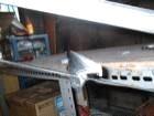
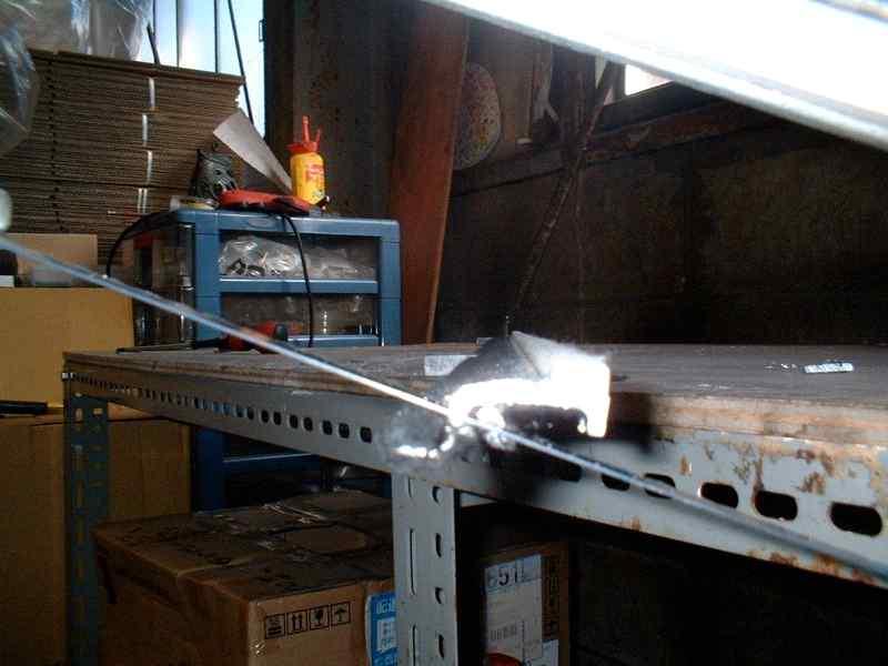
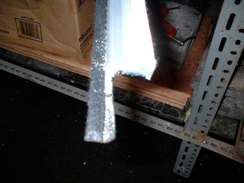
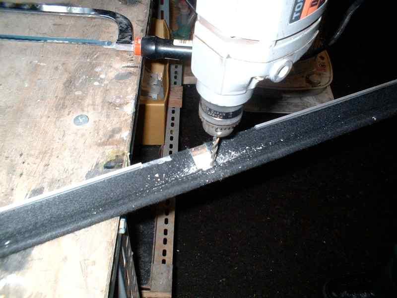
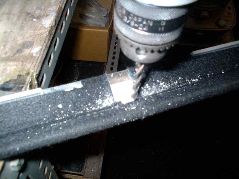
7 2. Mute Rail Working(STANDARD Type Mute Bar) 1) Cut the right edge with hacksaw 2) Keep cutting 3) 45 angle adjustable hacksaw is helpful. 4) Done. 5) Done. 6) Partial Cutting for centre bracket 7) After cutting, drill holes. 8) Drill holes


 Done.")


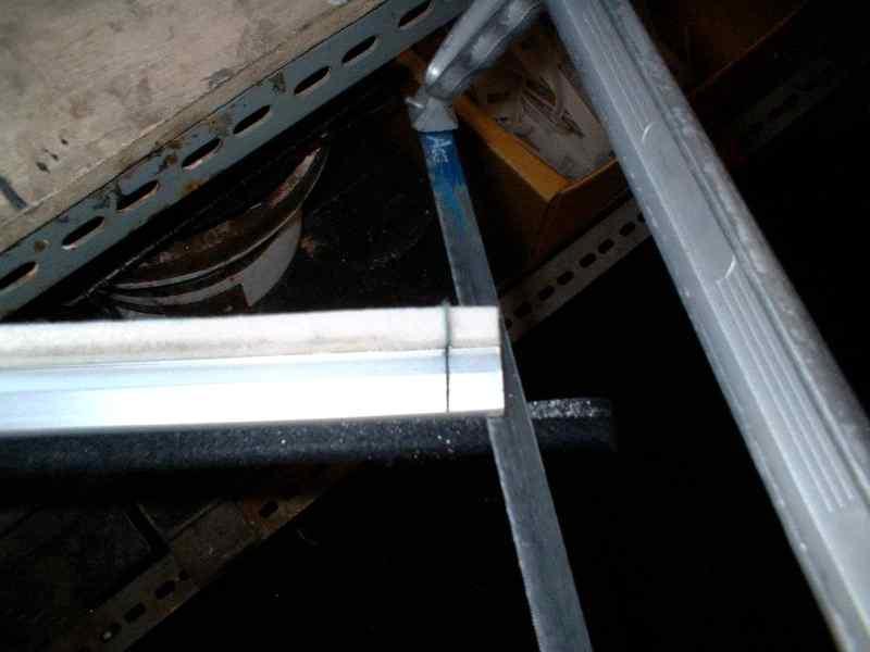
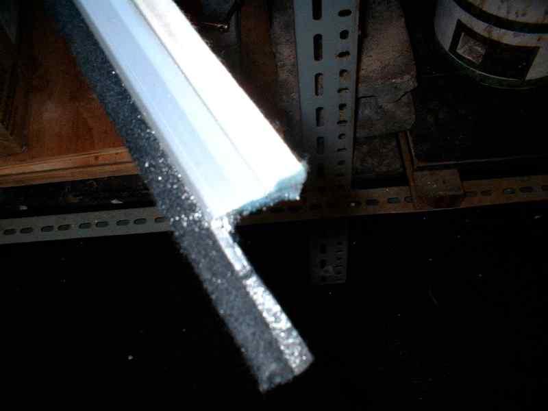
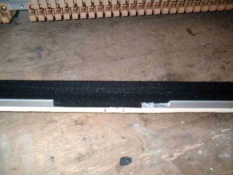
8 9) 3 holes done. 10) Bend with Flyer. 11) Done. 12) Done.(other side) 13) Filing 14) Put black felt with adequate size 15) Finished

 These screws should be re-used for mute rail installation.")
 (This screw is used for mute rail installation) In Yamaha pianos, it s")


9 3. Mute Rail Installation Check the length from the left to the right bracket If the centre bracket is interfered, refer to the prior 2. Mute rail cutting process. Separate the damper rail from action.(4 screws) These screws should be re-used for mute rail installation. ( Non use ) Treble part Second Treble part Bass part (This screw is used for mute rail installation) (This screw is used for mute rail installation) In Yamaha pianos, it s own L bracket in second treble part is re-used for mute rail installation. In Kawai, no need to use it s own Y bracket, replace it to L bracket provided. If the convex surface of upper side of the center rail where the damper flange is installed should be filed to be flat for L bracket fixing. For the other brand pianos, you need to decide how to install and exchange the brackets according to the shape and design of the actions.

 Fix the uni")


10 Mute Rail Installation Treble Part Bass part Second Treble Part (Bolt in damper side, nut in hammer side) Second Treble Part (Hold the nut with long-nosed plier) Fix the uni bracket into the stopper (mute rail) After install into action, make it almost straight line. Take out the felt in back side, adjust the screw position. Screw positions are adjustable

11 4. Mute Rail Adjustment after Installation (Important) It s the final process of mute rail installation for all hammers to be stopped at the same distance from the mute rail and from the strings when it s muted. The same distance from the mute rail cause in the same distance of let off for all hammers. If the distance is not even to each hammer, mute rail cannot work perfectly. When the hammer head and shank stops too far from the strings, it means the let-off points are too far from the strings too. And then, the whole acoustic piano mechanism would become un-balanced, So, the careful adjustment is required. Adjusting Process Summery 1 After the mute rail installation, install the action back to the piano, and clarify the 4 sections of bass part, middle part, second treble part and treble part. 2 Pulling the rail rod in left, put the hammer shank close against the rail cushion, And softly push the hammer heads in 4 sections to be touched to strings one by one. 3 Comparing with the other sections, the first hammer head touching slope is the basic gradient of the mute rail. (Normally, the second treble part or middle part can be the basic gradient, this basic section doesn t need the spacer put in) 4 After the basic section is decided, keep that hammer head touching, using the other hand, check the other hammer head how far(mm) the distance is from the string. 5 Keep this distance in mind, and add the spacer in between the stopper hinge and bracket to adjust the distance. 6 Take the action out and add the adequate spacers, and take the action back to the piano... and repeat checking again. 7 In every section, when every hammer head reach to the strings (with every hammer shank touches the rail felt), it is proved that the mute rail is perfectly parallel with strings. Top view of parallel strings and mute rail Strings Mute Rail Strings and mute rail are parallel. Bass Middle Second Treble Treble

12 Adjustment of Mute Rail Position 1 Before separating the action from the piano, measure the distance from the hammer head to the string when mute off position. For easy checking, push the hammer head to the string, and measure the distance between the hammer shank and hammer rail like the bellow picture. 2 Measure the above distances from the 4 points of bass, middle, second treble and treble part, and write down the 4 lengths to remember like bellow table. 3 Recommended mute-on position is 5 mm distance between hammer head and string, so write down the length at the next line after deducting 5 mm like bellow table. 4 Take out the action and install the mute rail according to the mute rail installation guide. Install the action into piano again, and measure the mute on distance again, and write down the real mute on distance. 5 And you can find the tolerance between the standard and real distance like bellow table 6 The biggest tolerance means the closest distance between the hammer head and string, and it becomes the basic section. Now, you can decide where you need to add spacer in order to make the mute rail parallel to the strings. (There are non 0.5 mm spacer, so just ignore +0.5 mm but just keep in mind) 7 Even though you adjust the distance with spacer correctly, the real distance can be different. So you need to adjust with spacers, and check it repeatedly until you find the correct position. (Unit : mm) Bass Middle Second Treble Treble Mute Off Range Standard Mute On distance Real Mute On Distance Tolerance Difference from basic section Add Spacer 1mm x 2 1mm x 1 The next page shows how to insert the spacers to adjust the mute rail distance.


13 Adjustment of Mute Rail Position Take out the action from piano. release the hinge screw where you need to adjust, insert spacer (3mm or 1mm) for adjusting the distance. Suitable Tool. Bass part (Normally, tapered spacer is not used. Just in special cases, it is used like when the mute rail should be leaned over more.) After adjustment of the mute rail position of front and back, set the spring and E ring. E ring Hook on After spring set, fix the E ring on the concave part of the rod front. After spring setting, screw the action bracket bolt. In order to prevent left and right shake of the mute rail, you may tight the [tie cable] in treble and bass parts.


14 5. Mute Lever Installation Natural looking wiring is needed for smooth wire movement. clamp 1cm come out when mute ON * The mute lever is installed in left side under the key bed, The customer can decide front and back position, but it s better to install 1cm come out from the key bed when the lever is ON. And fix the lever wire with clamp. As vertical straight as possible Hang the hook on the rod lever Put the ring in front of the rod. Position of uni bracket can be adjusted by the screws behind Mute Lever Installation


 There s a thin screw in right side of the mute")
15 Adjusting the postwar movements of mute rail (Pull Adjustment) Adjust the length. Loosen middle nut cable. Loosen joint cables, then mute rail tilts forward. Hammer shank stops earlier, and the distance between hammer and string getting far. Adjust to correct position Tighten middle nut cable. Recommended mute position is 5 ~ 6 mm distance between hammer head and string. But it depends on the situation. After joint cable adjusting, tighten the middle nut cable for fixing. The distance can be extended upon the request of piano player. 5~6mm Shank stop Strings Action bracket (Push Adjustment) There s a thin screw in right side of the mute lever box. When tightening with + screw driver, mute rail comes more closeer to the damper. Adjust this screw. For acoustic piano play, adjust the mute rail not to touch the hammer shank, and not to interfere the damper working.

16 Chapter 4. Sound Source Installation 1. Key Sensor Installation Take out every key and clean up key bed Remove Key sensor packing carefully. 1) Insert springs to the sensor plate. Turn the spring in this direction and insert Cut if it s long. Insert the spring s cross section into the plastic plate(since the cross section is sharp) 2) 5 sensor rail plates for upright pianos, and 4 ~ 5 plates for grand pianos are needed. Insert the plates into the sensor rail and fix it. Fix Directly Screw in key bed Don t use sensor plate. [Old Kawai doesn t need the sensor plate.] Set screw in 5 places (upright piano) Key sensor rail has 4 boards, so the best positioning of 5 sensor plates are the both bass and treble edges, and the 3 places where 4 boards are separated including the exact centre point. (Just in case of upright pianos)


17 Key Sensor Installation 3) Install key sensor on key bed. Insert the connector tightly Normally, the sensor cable can be passed under the key block, Sensor plate should be positioned to touch the front rail. 4) Tighten all of the screws a little bit for further adjustment. 5) Put 4 or 5 black keys close to the screws in order to adjust the key sensor s height.


18 Key Sensor Installation Adjust key sensors height. Adjust the precise height requirement of 1.75 mm gap between the top of sensor rail and the bottom of black key. Small difference can be adjusted by the Key Initializing Process after installation of the whole kit Attention : When pressing the key, do not make it touch with the back of actuator!
 After connecting the Signal Flat at the bottom of Main Unit, turn it around the Main")

19 2. Main Unit Installation Signal Flat : The flat cable connected between the Control Unit and the Main Unit 1) After connecting the Signal Flat at the bottom of Main Unit, turn it around the Main Unit like bellow picture, and install at the right side of the piano key bed inside 2) Connect the Key Sensors signal cable and Pedal signal cables to the correct jacks in right side of the Main Unit

 Install the Control")

20 3. Control Unit Installation 1) Pass the flat cable through the cable guide from the top and connect it with the control unit tightly. There s a black line on the Signal Flat at the opposite side of the Main Unit connection, and this black line should be correctly placed at the back side of the Control Unit s cable guide 2) Install the Control Unit under the right side of the key bed. The loosely fixing of the Signal Flat at the back of cable guide of the Control Unit makes the Control Unit s smooth sliding back and forth 3) Control & Main Unit Connection - Use the double sided adhesive tape for the fixing long Signal Flat under the key bed.

21 Control Unit Installation 4) Install the headphones hanger at the left or right beside the control unit. You can also hang the headphone at the back of the hanger. Control unit can be installed under the left side of the key bed, And then, you need to change the location of mute lever and headphones hanger installation Hanging on both front and back are available Clean arrangement of the cables connection inside the piano

22 4. Pedal Sensor Installation 1. There are two pedal sensors, One is for sustaining pedal and the other is for soft pedal. Sensor a ssy has two parts, one is base for fixing, and the other is sensor module. Pedal sensor can be installed at the top or the bottom of the pedal lever. Decide the location of the pedal sensor s installation after checking the pedal lever s moving and space on the bottom of the piano. Adjust the switch timing by adjusting the sensor up and down and tightening the screws. 1. Press up type 1. Press down type. 2. Switch works when pedal 2. Switch works when pedal lever goes up. lever goes down. Install close to the pedal lever. * Pedal lever left side Install the sensor carefully not to be pressed Sensors should be parallel with pedal lever.
 than acoustic")

 : The way of Initializing the key sensors and pedal sensors Right after")
![power on the system, immediately press and hold the [METRO.] button before the system gets ready.](/docs-images/77/74908249/images/23-3.jpg "Release [METRO.] button when the display shows the ready meaning.")
23 5. LET-OFF Adjustment 1. It s hammer stop mute system, so the hammer let-off should be a little bit longer (5~7 mm) than acoustic type (2~3 mm). Let he hammer shank let off 0.5 ~ 1 mm from the stopper(mute rail). If hammer shanks don t drop down properly for let-off, the key falls down improperly, as a result, the system cannot make the correct sound. * Calibration (Initialization) : The way of Initializing the key sensors and pedal sensors Right after power on the system, immediately press and hold the [METRO.] button before the system gets ready. Release [METRO.] button when the display shows the ready meaning. And press each of the 88 keys and all pedals. And press the [METRO.] button again to finish the initialization. (Refer to the User s Manual for more detail)) * Touch Button : Slightly touch the LETTERS bellow the button s icons Thank you.
Vertical Mute Rail Installation
 Vertical Mute Rail Installation Before you start the installation we recommend that you take note of the present state of the piano in which the QuietTime system with be installed into. 1. Check the over
A S e r v i ce Manual
 U p r ig ht Pian o R e gulatio n A S e r v i ce Manual Contents: 1. Clean the instrument... 2 2. Analyze the condition of the instrument... 3 3. Tighten all screws... 4 5. Position of wippen heel to the
Service Technicians Manual GRAND PIANOS MECHANISM REGULATION
 Service Technicians Manual GRAND PIANOS MECHANISM REGULATION 2008 1 Service Technicians Manual GRAND PIANOS MECHANISM REGULATION 1. General 1.1 Grand Pianos Storage Conditions at Shops and at Customers
KAWAI GRAND PIANO REGULATION MANUAL
 KAWAI GRAND PIANO REGULATION MANUAL Ver 1.4 2011/7/21 Piano Laboratory Supervisor Kazuo Goka 1 Regulation Process Index 1 Tighten all Plate Screws P3 2 Strike Point, Keyframe Position P4 3 Ease Keys P5
User Instructions Multiline Otter Scoreboard Caddy Assembly
 List of parts: User Instructions Multiline Otter Scoreboard Caddy Assembly Single Caddy Double Caddy 1 1 Base assembly with attached wheels 2 4 1 1 2 4 4 8 10 20 12 Uprights (60 or 74 aluminum extrusion)
Baby Grande or Grande Crank Shade with Cables and Housing Installation Instructions
 Baby Grande or Grande Crank Shade with Cables and Housing Installation Instructions Tools Needed Drill 3/8 Metal Drill Bit Screwdriver (Flat & Phillips) Measuring Tape Pencil 4 Level Plumb Line ¼ Masonry
Portofino Installation Guide
 vjul16 (for 17 or 24 mm Surface Wall Profiles) DO NOT ASSEMBLE WITHOUT FULLY READING THESE INSTRUCTIONS Page 2 Thank you for purchasing this Portofino shower enclosure. Please study these instructions
Replacing the Reciprocator on the SWF Compact Series Machine (601C and 1201C)
") Follow the instructions below to replace the reciprocator in the SWF Compact series machines. The tools required can be found in the tool kit that came with the machine. Preparation 1. First, place the
Follow the instructions below to replace the reciprocator in the SWF Compact series machines. The tools required can be found in the tool kit that came with the machine. Preparation 1. First, place the
Installation Instructions for FC2 & FC15 Forward Controls for the Super Magna
 Installation Instructions for FC2 & FC15 Forward Controls for the Super Magna It is highly recommended that you use a thread lock compound such as Loctite brand on all threads to keep them from vibrating
Installation Instructions
 by Plato Woodwork Installation Instructions Plato Woodwork, Inc. 200 Third Street SW P.O. Box 98 Plato, MN 55370 www.platowoodwork.com 800.328.5924 SECTION GUIDE GETTING STARTED PAGE # Installation Methods...
Portofino Case2 Installation Guide
 Portofino Case2 Installation Guide vjun16 (for 17 or 24 mm Surface Wall Profile) DO NOT ASSEMBLE WITHOUT FULLY READING THESE INSTRUCTIONS Page 2 Thank you for purchasing this Portofino Case 2 shower enclosure.
Deauville Installation Guide
 vjul16 (for 17 or 24 mm Surface Wall Profiles) DO NOT ASSEMBLE WITHOUT FULLY READING THESE INSTRUCTIONS Page 2 Thank you for purchasing this Deauville shower enclosure. Please study these instructions
FABA. Installation Instructions. Conductor Bar System. Publication #FABA-03 3/1/04 Part Number: Copyright 2004 Electromotive Systems
 FABA Conductor Bar System Installation Instructions Publication #FABA-03 3/1/04 Part Number: 005-1062 Copyright 2004 Electromotive Systems 1S 100 Z Installation Instructions Contents: Basic Diagram - -
Baby Grande or Grande Crank Shade with Cables and Housing Installation Instructions
 Baby Grande or Grande Crank Shade with Cables and Housing Installation Instructions Tools Needed Drill 3/8 Metal Drill Bit Screwdriver (Flat & Phillips) Measuring Tape Pencil 4 Level Plumb Line ¼ Masonry
TABLE OF CONTENTS REQUIRED TOOLS
 TABLE OF CONTENTS SECTION SECTION TITLE PAGE NO. 1 2 3 4 5 Assembling Mounting Structure Installing Bicycle Supports Mounting Rack to Wall Adding Sections Customizing Rack Configuration REQUIRED TOOLS
INSTALLATION INSTRUCTIONS 3 BULL BAR 99-04, 04 "HERITAGE" F-150/250LD 2WD, 97-04, 04 "HERITAGE" 4WD WD EXPEDITION/ WD EXPEDITION PART
 INSTALLATION INSTRUCTIONS 3 BULL BAR PART #B-F1971;B-F2971 PARTS LIST: 1 Bull Bar 2 12-1.75mm x 130mm x 40mm Hex Bolts 1 Driver/Left Mounting Bracket 4 12-1.75mm x 35mm Hex Bolts 1 Passenger/Right Mounting
Jass.Performance Low Profiles Installation Manual
 Jass.Performance Low Profiles Installation Manual What is in the box: 2x Adapter Frame 2x Outer Panels 2x Inner Panels Pushrod, Ball Joints & Brackets 2x Hella Headlights 6x Springs 4x M6x25 Cross Head
INSTALLATION INSTRUCTIONS RH 412 STEEL DOORS
 By following the steps outlined below, the assembly, installation and adjustment of the steel doors, will be a simple process. Let s start with the Driver Side. Note: Having the hood open makes the job
Mount to the Wall INSTALLATION MANUAL
 Mount to the Wall 15 Locate the Wooden Studs This step applies to wooden stud wall installation only. Determine and mark the exact locations of two stud centers on the wall. Wooden studs should be spaced
C70 Window Roller Repair Taken from: Heres the problem:
 C70 Window Roller Repair Taken from: http://www.volvospeed.com/vs_forum/topic/115086-how-to-c70-window-rollers-permanent-fix/ Heres the problem: This happened to two separate window assemblys on my c70
TOOL LIST FOR TAILGATE HIDDEN LATCH & LINK ASSY FOR FORD FLARESIDE TRUCKS
 TOOL LIST FOR TAILGATE HIDDEN LATCH & LINK ASSY FOR 53-87 FORD FLARESIDE TRUCKS Vise Grip Clamps C-clamps Sharpie Marker Ball Peen Hammer Center Punch 3/8 or 1/2 Drill 5/32, 7/32, 9/32, and 3/8 Drill Bits
Studio Face Xtreme 6020 Installation Instructions (Nickel , Black )
") Packing List Face Trim (4 Pieces) (3) Hanging Brackets (9) 3/16 x 1-1/4 Masonry Screws 9/64 Drill Bit Compatibility (2) Lower Brackets w Magnets (2) Lower Facing Plates (4) 2 Drywall Screws Trim Hardware
Packing List Face Trim (4 Pieces) (3) Hanging Brackets (9) 3/16 x 1-1/4 Masonry Screws 9/64 Drill Bit Compatibility (2) Lower Brackets w Magnets (2) Lower Facing Plates (4) 2 Drywall Screws Trim Hardware
Hatchback Wing Riser Kit
 Hatchback Wing Riser Kit 2015-06-11 Thank you for purchasing this PERRIN product for your car! Installation of this product should only be performed by persons experienced with installation of aftermarket
SAM. Model: STV-C65 LCD Mobile Visualized Stand Instruction Manual. Weight Capacity: 1251bs / 56.7kg Suits LCD Flat Panel Display: 42"-55" Page 20
 SAM Model: STV-C65 LCD Mobile Visualized Stand Instruction Manual Weight Capacity: 1251bs / 56.7kg Suits LCD Flat Panel Display: 42"-55" 20 Step 6 LCD Mobile Lift Stand Model: STV-C65 Cable management
Tools Needed Hardware Provided (per shade) Hardware Needed
 Hardware Needed") Baby Grande or Grande Motorized (XQ5 Premium) Shade with Cables and Housing Installation Instructions Tools Needed Hardware Provided (per shade) Hardware Needed Drill 3/8 Metal Drill Bit Measuring Tape
Baby Grande or Grande Motorized (XQ5 Premium) Shade with Cables and Housing Installation Instructions Tools Needed Hardware Provided (per shade) Hardware Needed Drill 3/8 Metal Drill Bit Measuring Tape
Ford Pick Up Rear leaf Spring Kit Installation Instructions
 1948-1956 Ford Pick Up Rear leaf Spring Kit Installation Instructions 1-800-984-6259 www.totalcostinvolved.com Parts 48 inch leaf (2) springs (4) U-bolts 3/8-24 x l 1/4bolts (16) & nuts (2) 1/2-20 x 4
CAL-K1 Self-build guitar kit UK Version 1.0
 CAL-K1 Self-build guitar kit 174.460UK Version 1.0 Thank you for buying the CAL-K1 kit. All the wood, hardware and electrical components of a Chord CAL93 guitar are contained in this package. Please read
For installation assistance, contact SARGENT at DOORS SHOWN HERE SWING IN FOR ILLUSTRATION PURPOSES ONLY.
 SARGENT Installation Instructions for LP8600 x LR8600 & 12-LP8600 x 12-LR8600 Series Low Profile Panic and Fire Exit Devices on Double Egress & Double Doors or LS8600 & 12-LS8600 Low Profile Exit Device
WARNING: Prior to installation, turn the power off to the vending machine and unplug it from its power source. Also, make sure to level the machine.
 Installation of Gum and Mint Tray for National 147, 157, 167 Important Note: Please read all instructions thoroughly before continuing with installation of kit. If you are having problems installing the
Work Space Set-up. Slats will level the pipe during bending and help minimize twisting of the bow.
 Work Space Set-up Affix pipe bender to end of working surface Slats will level the pipe during bending and help minimize twisting of the bow. Make the slat height equal the distance from your work surface
RH-412 STEEL DOORS INSTALLATION INSTRUCTIONS
 RH-412 STEEL DOORS INSTALLATION INSTRUCTIONS By following the steps outlined below, the assembly, installation and adjustment of the steel doors, will be a simple process. Let s start with the Driver Side.
Hardware and Components:
 Hardware and Components: (A) 5/16 x 2 Hex Bolt (B) 5/16 x 2-1/4 Hex Bolt (C) 5/16 x 2-1/2 Hex Bolt (D) 4X 5/16 x 3/4 Hex Bolt (E) 4X 5/16 x 1-1/4 Hex Bolt (F) 11X 5/16 Flat Washer (G) 12X 5/16 Nylock Nut
Deauville Installation Guide
 vjul16 (for Recessed Wall Profiles) DO NOT ASSEMBLE WITHOUT FULLY READING THESE INSTRUCTIONS Page 2 Thank you for purchasing this Deauville shower enclosure. Please study these instructions carefully before
Chapter 18. Interior Doors
 Chapter 18. Interior Doors 18.1 SWINGING DOORS 18.2 SLIDING DOORS 18.3 BIFOLD DOORS Tools needed by volunteers: Hammer Nail apron Tape measure Square Pencil Tools and equipment needed: Extension cords
Kossel Rev B Build Guide V1.0
 Kossel Rev B Build Guide V1.0 1 Table of Contents: Step 1: BASE ASSEMBLY Gathering parts: Building the Corners and Base: Step 2: UPPER ASSEMBLY Building Upper: Step 3: VERTICAL RAIL INSTALLATION Building
INSTALLING YOUR NEW SPRING LIFT ARM KIT
 INSTALLING YOUR NEW SPRING LIFT ARM KIT 1. Measure the distance that the roof is to be raised. [If your lift system is completely non-functional, you will need to calculate or estimate this distance as
8mm x 25mm "Z" Bolt Plates. (2) Tube Spacers. (2) 12mm Bolt Plates w/ Nut
 Tube Spacers. (2) 12mm Bolt Plates w/ Nut") PARTS LIST: 1 Grille Guard 10 12mm Lock Washers 1 Driver/Left Side Frame Mounting Bracket 8 12mm Hex Nuts 1 Passenger/Right Side Frame Mounting Bracket 2 10-1.50mm x 25mm Button Head Bolts 1 Driver/Left
PARTS LIST: 1 Grille Guard 10 12mm Lock Washers 1 Driver/Left Side Frame Mounting Bracket 8 12mm Hex Nuts 1 Passenger/Right Side Frame Mounting Bracket 2 10-1.50mm x 25mm Button Head Bolts 1 Driver/Left
MM540 Installation Instructions IMPORTANT SAFETY INSTRUCTIONS - SAVE THESE INSTRUCTIONS
 MM50 Installation Instructions IMPORTANT SAFETY INSTRUCTIONS - SAVE THESE INSTRUCTIONS Please read this entire manual before you begin. Do not unpack any contents until you verify all requirements on PAGE.
Owner s Manual. Bass-Guitar Kit J-Style
 Owner s Manual Bass-Guitar Kit J-Style Contents Introduction... 3 Body finish... 4 Neck finish... 4 Assembling of tuners... 5 Neck... 6 Wiring... 6 Bridge assembly... 8 Strap buttons... 8 Setting up...
(Assembling Guide supplied by imakr ) with the support of MyMiniFactory.com
 with the support of MyMiniFactory.com") (Assembling Guide supplied by imakr ) with the support of MyMiniFactory.com Summary Congratulations on beginning on your journey into 3D printing with the STARTT 3D printer. In this guide, you will have
(Assembling Guide supplied by imakr ) with the support of MyMiniFactory.com Summary Congratulations on beginning on your journey into 3D printing with the STARTT 3D printer. In this guide, you will have
DeRosa DRM-516 (5-PIECE 16 ) Drum Kit ASSEMBLY INSTRUCTIONS
 Drum Kit ASSEMBLY INSTRUCTIONS") DeRosa DRM-516 (5-PIECE 16 ) Drum Kit ASSEMBLY INSTRUCTIONS Along with reading this guide, we also recommend that you watch the DeRosa 516 Drum Kit Assembly video on the Austin Bazaar Product FAQ page
DeRosa DRM-516 (5-PIECE 16 ) Drum Kit ASSEMBLY INSTRUCTIONS Along with reading this guide, we also recommend that you watch the DeRosa 516 Drum Kit Assembly video on the Austin Bazaar Product FAQ page
EmagiKit. Privacy Pod Plus. Quiet. Easy. Affordable. INSTRUCTIONS ASSEMBLY
 EmagiKit Privacy Pod Plus Quiet. Easy. Affordable. INSTRUCTIONS ASSEMBLY DIMENSIONS AND COMPONENTS 47 47 Ceiling Unit 2-B 2-L 2-R Glass Door Corner Trim Door Handle 90 Adjustable Height Work Surface 1-B
RACER TECH COMMANDER HD TIE ROD INSTALLATION
 RACER TECH COMMANDER HD TIE ROD INSTALLATION NOTE: These instructions are a universal explanation of how to install our HD Tie Rods. All kits are identical for all inner joints and nearly identical for
Extendable Large Dovetail Jig
 Extendable Large Dovetail Jig Instruction Manual Part # 3458 CAUTION: Please read, understand, and follow all manufacturers instructions, guidelines and owners manuals that come with your power tools.
BABY WOLF LOOM. Assembly Instructions for Knocked-Down Looms
 BABY WOLF LOOM Assembly Instructions for Knocked-Down Looms BEFORE YOU BEGIN Please read through the directions before beginning to assemble your loom. Unpack the loom parts carefully. Do not throw away
Closet System Installation Manual
 Closet System Manual Thank you For choosing our Custom Closet Collection to fit all your needs Closets come fully assembled to make your project an enjoyable and satisfying experience. With quality Custom
B A T H R O O M G L A S S
 mistley B A T H R O O M G L A S S vaug16 Page 2 Thank you for purchasing this Trinity shower screen. Please study these instructions carefully before assembly and installation and check all supplied parts
TP4463. ASSeMBly INSTruCTIONS FLAT PANEL TV MOUNTING SYSTEM OPTION 1 OPTION 2 OPTION 3
 TP63 FLAT PANEL TV MOUNTING SYSTEM OPTION 1 OPTION 2 OPTION 3 Flat Panel TV Stand Stand with TV Mounting System Stand with Wall Mount ASSeMBly INSTruCTIONS for your safety, please follow these precautions:!
16ft Polytunnel Assembly Instructions
 CONTENTS Section Page 1. FOUNDATION TUBES: Option A Ground Anchor Plates 3 2. FOUNDATION TUBES: Option B Concreted Foundation Tubes 5 3. STEEL FRAME ASSEMBLY & INSTALLATION 6 4. CROP BARS 8 5. TIMBER END
woodworkersjournal.com MATERIAL LIST
 MATERIAL LIST T x W x L 1 Legs (2) 1 1 2" x 3 1 2" x 36 7 16" 2 End Uprights (2) 1 1 2" x 3 1 2" x 32 1 2" 3 Stringers (4) 1 1 2" x 3 1 2" x 42" 4 Top Cladding, Long (2) 3/4" x 7 1 4" x 65 3 4" 5 Side
15 Dovetail Jig. Instruction Manual. Part # 3452
 15 Dovetail Jig Instruction Manual Part # 3452 CAUTION: Please read, understand, and follow all manufacturers instructions, guidelines and owners manuals that come with your power tools. Peachtree Woodworking
(2) 25mm x 20mm x 5mm Adhesive Backed Foam Pads. 100mm x 50mm x 1.0mm Adhesive Backed Foam. (2) Spacer Plates. Passenger/Right Side Frame Mounting
 25mm x 20mm x 5mm Adhesive Backed Foam Pads. 100mm x 50mm x 1.0mm Adhesive Backed Foam. (2) Spacer Plates. Passenger/Right Side Frame Mounting") PARTS LIST: 1 Grille Guard 10 12mm Lock Washers 1 Driver/Left Frame Mounting 16 12mm x 32mm OD x 3mm Flat Washers 1 Passenger/Right Frame Mounting 8 12mm Hex Nuts 1 Driver/Left Side Top Support 2 10-1.50mm
PARTS LIST: 1 Grille Guard 10 12mm Lock Washers 1 Driver/Left Frame Mounting 16 12mm x 32mm OD x 3mm Flat Washers 1 Passenger/Right Frame Mounting 8 12mm Hex Nuts 1 Driver/Left Side Top Support 2 10-1.50mm
Octagon Vinyl Gazebo Assembly Instructions For 10 & 12 Models
 Octagon Vinyl Gazebo Assembly Instructions For 10 & 12 Models Toll Free: 866.768.8465 Hours: 9-5 Monday-Friday EST www.homeplacestructures.com Package ships as shown revised 04/29/09 Vinyl Gazebo Assembly
Breathable Wall Light Traps & Blackout Fan & Shutter Kits
 Breathable Wall Light Traps & Blackout Fan & Shutter Kits 2017 Growers Supply All Rights Reserved. Reproduction is prohibited without permission. Maintain controlled airflow without sacrificing blackout
MM340 Installation Instructions IMPORTANT SAFETY INSTRUCTIONS - SAVE THESE INSTRUCTIONS
 MM30 Installation Instructions IMPORTANT SAFETY INSTRUCTIONS - SAVE THESE INSTRUCTIONS Please read this entire manual before you begin. Do not unpack any contents until you verify all requirements on PAGE.
`48-`56 Ford Pickup Rear leaf Spring Kit Installation Instructions Tech Line:
 `48-`56 Ford Pickup Rear leaf Spring Kit Installation Instructions Tech Line: 1-855-693-1259 www.totalcostinvolved.com CHECK ALL PARTS INCLUDED IN THIS KIT TO THE PARTS LIST BEFORE INSTALLING THE KIT.
Hardware and Components:
 Hardware and Components: (A) 4X 5/16 x 1 Carriage Bolt (B) 2X 5/16 x 2-1/4 Carriage Bolt (C) 2X 5/16 x 3-1/4 Hex Bolt (D) 2X 5/16 x 3/4 Hex Bolt (E) 2X 5/16 x 1-1/4 Hex Bolt (F) 5/16 x 2-1/4 Hex Bolt (G)
Installation Instruction
 Tools Needed for Assembly Stud finder (for wood stud wall) Pencil Mark Electric drill Wood Stud Wall Installation Step 1. Locate the Wood Studs Installation Instruction Drill bit (for wood stud wall) Masonry
Deck Mount Installation with Bench
 Deck Mount Installation with Bench 1. Mark track with square. 2. Cut tracks with saw. 3. Drill ¼ hole (if needed.) 4. Countersink track. 5. Countersink all track 6. File all track ends. ends. 7. Lay out
Assembly Instructions 10 X 10 Aluminum Frame Building
 Assembly Instructions 10 X 10 Aluminum Frame Building 27 97 9 8 47 36 74 52 10 10 X 10 Square Building W/ Dome Includes: The Steel Entry Door with a Dead Bolt Lock assembly and Aluminum Door Frame. Metal
CV1B Sliding Table Installation and Setup Guide
 CV1B Sliding Table Installation and Setup Guide Tech Mark, Inc 7901 Industry Drive North Little Rock, AR 72117 tel (501) 945-9393 fax (501) 945-0312 www.tech-mark.com email: info@tech-mark.com The CV1B
Electric Mid-Drive. Installation and Assembly Instructions for Catrike 26 and 700c
 Electric Mid-Drive Installation and Assembly Instructions for Catrike 26 and 700c copyright 2009, EcoSpeed LLC http://www.ecospeed.com/docs/emd22_assy_rev1.01 Revision 1.01 p/n 7-10-22 1 2 Electric Mid-Drive
GROWING BETTER THROUGH DESIGN. 6ft Lean-To LEAN-TO. Assembly Instructions 04/02
 GROWING BETTER THROUGH DESIGN 6ft Lean-To LEAN-TO Assembly Instructions 04/02 6ft Lean-To Greenhouse Base Plan Introduction/Tools/Contents / / Contents This is a copy of our Lean-To greenhouse base plan.
Assembly Instructions
 10' and 12' Octagon Cedar Gazebo Assembly Instructions Toll Free: 866.768.8465 Hours: 9-5 Monday-Friday EST www.homeplacestructures.com Package ships as shown revised 06/20/09 Cedar Gazebo Assembly Instructions
Monaco Installation Guide - Surface Profiles
 v1 Page 1 Thank you for purchasing this Monaco shower screen. Please study these instructions carefully before assembly and installation and check all supplied parts immediately upon receipt. These instructions
GoPro Hero Camera Mount. Assembly Manual
 GoPro Hero Camera Mount Assembly Manual Introduction Thank you for purchasing the GoPro Hero Camera Mount for Mikrokopter Quad, Hexa and Okto. The Camera Mount is provided as a kit and requires assembly.
HQ Precision-Glide Track Upgrade 2 Extension Kit for HQ Studio Frame Part# QF09750
 HQ Precision-Glide Track Upgrade 2 Extension Kit for HQ Studio Frame Part# QF09750 Important Note: Upgrading the track system on the HQ Studio Frame requires the use of this 2 Extension Kit (Part #QF09750),
General Features. Low Profile. The SMART BOXX stands only 1.5 off of the bed of your truck so cargo space is maximized
 General Features Low Profile. The SMART BOXX stands only 1.5 off of the bed of your truck so cargo space is maximized Two Sizes Short Box :74 L X 47 W X 7 T and Long Box 92 L X 47 W X 7 T All Aluminium
TRUE TECHNICAL SERVICE MANUAL - ALL MODELS. DOORS/DRAWERS/LIDS
 DOORS/DRAWERS/LIDS 55 56 NOTES DOORS/DRAWERS/LIDS Swing s 73 74 NOTES INSTALLATION OF A GDM-SWING DOOR Phillips Head Screwdriver (2) - 1/8" Drift Punches (forged) Top Bracket NOTE: It may be necessary
INSTALLATION INSTRUCTIONS
 TEL -866-XANATOS INSTALLATION INSTRUCTIONS PART#: 7D5000SS\7D500A GRILL GUARD FOR DODGE SPRINTER 07-09 PARTS LIST: 8 6 Grille Guard Driver/Left Frame Mounting Passenger/Right Frame Mounting Driver/Left
TRUE TECHNICAL SERVICE MANUAL - ALL MODELS. DOORS/DRAWERS/LIDS
 DOORS/DRAWERS/LIDS 55 56 NOTES DOORS/DRAWERS/LIDS Springs 97 TORSION SPRING REPLACEMENT GDM RADIUS FRONT - SWING DOOR INSTALLATION INSTRUCTIONS Tools Required (2) - 1 8" drift Punch (forged) Needle-Nose
Removing outter components
 Y Axis Motor Replacement Replacing the Y axis motor is a process that requires the individual to be somewhat mechanically inclined and can follow detailed instructions. If any of the following steps are
Two Panel Frameless Bypass Door
 INSTALLATION INSTRUCTIONS Two Frameless Bypass Door Series 00 Please Record Model Number From Carton Label Here Please read these instructions carefully to familiarize yourself with the required tools,
Instruction Manual. Manual Furniture Mover. Note: Owner/Operator must read and understand this instruction manual before using the furniture mover.
 Instruction Manual Manual Furniture Mover Note: Owner/Operator must read and understand this instruction manual before using the furniture mover. I - Contents 1. Application 2 Specifications 3.Assembly
FIXED PANEL SLIDER QCI5241
 INSTALLATION INSTRUCTIONS FIXED PANEL SLIDER QCI5241 FRAMELESS PANEL / DOOR / PANEL FRAMELESS DOOR / PANEL QCI5241 REV. 0 Page 1 Certified 06/16/2016 Parts List *Quantities may vary QCI5241 REV. 0 Page
MantelMount. TM1A Installation Instructions IMPORTANT SAFETY INSTRUCTIONS - SAVE THESE INSTRUCTIONS
 MantelMount TMA Installation Instructions IMPORTANT SAFETY INSTRUCTIONS - SAVE THESE INSTRUCTIONS TM Thank you for choosing the MantelMount television wall mount. Please read this entire manual before
STORAGE & SHELVING SYSTEM - INSTALLATION GUIDE
 STORAGE & SHELVING SYSTEM - INSTALLATION GUIDE If you have ordered storage drawers, shelving, hanging rails or shoe racks this guide will help you install your storage and shelving system, together with
ELIZABETH 30 SPINNING WHEEL
 INSTRUCTIONS ELIZABETH 30 SPINNING WHEEL Single and Double Treadle Ashford Handicrafts Ltd. Factory and Showroom: 415 West Street, PO Box 474, Ashburton, New Zealand Telephone 64 3 308 9087 Facsimile 64
Hawko Zhaga Systems Installation Instructions
 Hawko Zhaga Systems Installation Instructions Contents Wire Suspension Installation 4 Recessed Brackets 6 Fixed Suspension Rods 8 Swivel Suspension Rods 10 Surface Mount Ceiling 12 Surface Mount Wall
AUDI A8 D3 REPLACING THE OUTSIDE DRIVER DOOR HANDLE
 AUDI A8 D3 REPLACING THE OUTSIDE DRIVER DOOR HANDLE The keyless entry system in the D3 is a great feature. If you have the car key fob in your pocket, putting your hand under the door handle will unlock
INSTRUCTIONS FOR ASSEMBLING YOUR CLEARMOUNT MITER SAW SCALE
 INSTRUCTIONS FOR ASSEMBLING YOUR CLEARMOUNT MITER SAW SCALE Pictures shown are our SW7 but these instructions apply to all of our scales. Special information for other models is noted. ** Read & Follow
* Drill and 3/32" drill bit: for drilling holes in the factory plastic upper for the screws to secure the brackets (factory upper installation only)
") * Two slider windows (four sliders windows for the 4-door kit) * Four brackets to secure the windows to the upper door frames (8 brackets for the 4-door kit) * Weatherstrip to seal the windows to the half
* Two slider windows (four sliders windows for the 4-door kit) * Four brackets to secure the windows to the upper door frames (8 brackets for the 4-door kit) * Weatherstrip to seal the windows to the half
1. Layout. Step 1. Step 2. Step 3. Fig. 1
 1-3/8 Panel Clamp Tools You Will Need: Tape Measure, Mason s String, Stakes, Hole Digger, Shovel, Level, Wheelbarrow, Wrenches or Adjustable Wrench, Hacksaw, Pliers, Cutting Pliers, Fence Stretcher and
Castle Frame Assembly Table AT-8. Diagnostics Manual. Castle, Inc. Petaluma, CA
 Castle Frame Assembly Table AT-8 Diagnostics Manual Castle, Inc. Petaluma, CA 800-282-8338 Solutions Index Adjusting the Tabletop.. 8.01 Adjusting the Fence... 8.02 Aligning the Arm... 8.10 Adjusting Bracket..
INFINITE RANGE - CENTRE FOLDING DOOR
 INFINITE RANGE - CENTRE FOLDING DOOR CENTRE FOLDING DOOR ONLY ( RECESS) Please read these instructions before installing, as incorrect fitting will invalidate the guarantee-carry out each stage before
BioPrism Solid Surface
 Please read all instructions before installing products. These instructions are intended for use with InPro s standard toilet partitions, which include 58 high doors and wall panels, when deviating from
Cap frame (Shaft-less type)
") Cap frame (Shaft-less type) Installation manual ** Model : XT-CAII / XT-CBII / XT-CII / XY-CII / XS-C ** 1: Wide cap frame -------------------------------------------------------------Page 2 2: Semi-wide
Cap frame (Shaft-less type) Installation manual ** Model : XT-CAII / XT-CBII / XT-CII / XY-CII / XS-C ** 1: Wide cap frame -------------------------------------------------------------Page 2 2: Semi-wide
GREENHOUSE 6'x8' ASSEMBLY INSTRUCTIONS. (Internal Dimensions) Overall Dimensions (Approx.) L 193 W 200 H cms 97.5" L 76" W 78.
 Overall Dimensions (Approx.) L 193 W 200 H cms 97.5 L 76 W 78.") ASSEMBLY INSTRUCTIONS GREENHOUSE 'x8' (Internal Dimensions) Overall Dimensions (Approx.) 7. L 9 W 00 H cms 97." L 7" W 78.8" H 0 IMPORTANT You must read these instructions carefully before you start to
ASSEMBLY INSTRUCTIONS GREENHOUSE 'x8' (Internal Dimensions) Overall Dimensions (Approx.) 7. L 9 W 00 H cms 97." L 7" W 78.8" H 0 IMPORTANT You must read these instructions carefully before you start to
Assembly and Installation Guide
 The Easy Hang Closet Solution SM Install Your elfa In An Instant. Enjoy The Benefits For A Lifetime. Basic Tools For elfa Assembly and Installation Level Hand or Power Drill Drill Bits 1/8", 3/8", 5/16"
How to install backchecks
 How to install backchecks Note: All pictures can be enlarged for better clarification. Revision 7 8/2009 Backchecks wear out in a piano much like brake pads in an automobile. While wear is a valid reason
Video Wall Installation Instructions 2W X 3H, 3W X 3H
 Video Wall Installation Instructions 2W X 3H, 3W X 3H www.microndisplaysolutions.com Table of Contents Important Safety Instructions... 3 Configuration... 4 Package Contents, included and optional items...
Technicians of Terror. This is the air valve we make to use with our air
 These are pictures of our scissor prop. Technicians of Terror http://www.halloweenfear.com/scissorprop.html props. This is the air valve we make to use with our air This pictures the duel door closer cylinders
Heavy-Duty Bypass Track System
 Heavy-Duty Bypass Track System Please Note: This track system must be installed with the screws going into a solid surface such as studs or a header. Due to the spacing of the holes on these Brackets,
Grade 8 Enriched Math Catapult Project 2012 Step by Step Instructions to building a catapult
 Grade 8 Enriched Math Catapult Project 2012 Step by Step Instructions to building a catapult Grade 8 Enriched Math Project INSTRUCTION SHEET FOR CATAPULT Procedures, materials and tools: below is a step-bystep
MM750 Installation Instructions
 MM750 Installation Instructions IMPORTANT SAFETY INSTRUCTIONS - SAVE THESE INSTRUCTIONS Please read this entire manual before you begin. Do not unpack any contents until you verify all requirements on
 Menu Board Tilt or Fixed Mount Installation Instructions MDS1T-200, MDS1T-300, MDS1T-400 MDS2T-200, MDS2T-300, MDS2T-400 MDS3T-200, MDS3T-300, MDS3T-400 MDS4T-200, MDS4T-300, MDS4T-400 MDS5T-200, MDS5T-300,
TOOLS REQUIRED FOR ASSEMBLY. Rubber Mallet or Plastic Tip Hammer PARTS REQUIRED FOR ASSEMBLY OF SINGLE ENTRY STARTER.
 TOOLS REQUIRED FOR ASSEMBLY Rubber Mallet or Plastic Tip Hammer Top Cover Support PARTS REQUIRED FOR ASSEMBLY OF SINGLE ENTRY STARTER Back Stop Divider Closed 'L' Upright Slotted Reinforcement Support
BX3615. Subaru Impreza WRX (Include STI) Subaru 2012 Impreza Premium 2010 Outback Sport Installation Instructions Attachment Tab Height: 15
 Subaru 2012 Impreza Premium 2010 Outback Sport Installation Instructions Attachment Tab Height: 15") 1. Blue Ox towing products and accessories are intended to be installed by Blue Ox Dealers who are familiar with our products and have the equipment and knowledge necessary to do fit work. If needed, Blue
1. Blue Ox towing products and accessories are intended to be installed by Blue Ox Dealers who are familiar with our products and have the equipment and knowledge necessary to do fit work. If needed, Blue
Codonics SLS 500i Shelf Installation
 Codonics SLS 500i Shelf Installation Blue Bell Cart or Generic Blind Mounting Technical Brief Overview This document explains how to properly install the Codonics Safe Label System SLS 500i shelf with
PARTS INCLUDED IN FIXED STAIR CABLE RAIL KIT:
 175 SERIES FIXED STAIR CABLE RAIL - INSTALLATION INSTRUCTIONS PARTS INCLUDED IN FIXED STAIR CABLE RAIL KIT: FIXED STAIR TOP RAIL (1) A FIXED STAIR BOTTOM RAIL (1) B D UPPER SADDLE BRACKET (1) C BRACKET