ARCHLine.XP Interior Windows. Learning Interior. Learning material for the basics of ARCHLine.XP Interior. ARCHLine.
|
|
|
- Tiffany Bell
- 5 years ago
- Views:
Transcription
1 ARCHLine.XP Interior 2010 Windows Learning Interior Learning material for the basics of ARCHLine.XP Interior ARCHLine.XP Interior
2 Information in this document is subject to change without notice and does not represent a commitment on the part of CadLine. The software, which includes the information contained in any databases, described in this document is furnished under a license agreement or nondisclosure agreement. The software may be used or copied only in accordance with the terms of the agreement. It is against the law to copy the software on any medium except as specifically allowed in the license or nondisclosure agreement. The licensee (purchaser) may make one copy of the software for the purpose of creating a -backup copy. No part of this manual may be reproduced, transmitted, transcribed, or translated into any language in any form or by any means, without the express written permission of CadLine. First Edition 2010 CadLine. All rights reserved. In no event shall CadLine be liable for special, indirect or consequential damages in connection with or arising from the use of this document or any programs contained herein. Microsoft, MS, and MS-DOS are registered trademarks and Windows is a trademark of Microsoft Corporation. ARCHLine.XP is a trademark of CadLine. This tutorial was produced using Microsoft Word and ARCHLine.XP. CadLine
3 CONTENTS Preparation...5 Starting a new project...6 Toolbox and Navigation...8 General preferences...10 Using existing drawings...12 Building...15 Outer walls...16 Partition walls...24 Paling pictures, locking layers...26 Openings...27 Slabs...34 Floors...35 Roof...38 Roof structure...42 Flat roof...44 Interior design...46 Navigation in the 3D window...47 Floor plan changes...48 New curved walls...51 Comparison between different versions...55 Walls with unique shape...57 Shelves...60 Covering walls...62 Tiling on floor...64 Furnishing in the kitchen...69 Colouring the walls in the living room...72 Furnishing in the living room by means of the Google 3D Warehouse...77 Drapery...81 Light sources...83 Sun shadows...85 Picture on wall...87 Documentation...89 New drawing window for the colour plan...90 Dimensioning...92 Section, interior elevation...96 Floor plan with textures and materials...98 Composing a plot layout Printing ARCHLine.XP Interior

4 4 Learning Interior How to use the guide? Welcome to our guide! We are going to take a look at the use of ARCHLine.XP INTERIOR. We are going to work according to the data of a local survey scan and will make the project of the interior decoration following the guidelines of the customer. Every chapter begins with the description of the task to perform (1). You can execute it yourself after trying the tips in the grey frames (2) or follow the detailed documentation under the Step by step section (3). This guide introduces the most frequently used tools of ARCHLine.XP INTERIOR. We have generally followed the simplest way, trying other possibilities is recommended as well. You can find the detailed documentation of the commands in the Manual or in the Help (F1). You can follow the steps of this guide by watching the tutorial videos at the website as well. It is recommended to use this guide and the videos together. If you have any question, do not hesitate to contact your ARCHLine.XP INTERIOR partner. CadLine
5 Preparation 5 PREPARATION ARCHLine.XP Interior

6 6 Learning Interior STARTING A NEW PROJECT We are going to work on a new project that contains all the drawings we have made so far. This time Interior.pro is the name of the project and we have to save it. How to work with projects? After starting the program a dialog appears. (In case of using the Trial Version, first you can choose between sample projects, you can get to the next screen which you can see on the image below by pressing the More button.) Now you can decide whether to start a new project or continue an existing one. If you start a new project, you have to save this empty project immediately. You can reopen later this dialog by selecting New Project in the File menu. How to save a project? After finishing your work you can save it by selecting Save Project in the File menu. In the appearing dialog you can determine those parts of the project that you intend to save. If you do not change anything in settings, the whole project will be saved. CadLine

7 Preparation 7 Step by step Run ARCHLine.XP. When a dialog appears press the New Project button. Save the new project as Interior.pro. After opening the new project the Tips window appears. Go through its content, and then close the window. ARCHLine.XP Interior

8 8 Learning Interior TOOLBOX AND NAVIGATION Before starting the work, get acquainted with the most important elements of the user interface: the toolbox and the navigation on the drawing. CadLine

9 Preparation 9 How to use the Toolbox? The Toolbox on the left side of the screen is going to be the main unit of our work. The order of the tools in the Toolbox will guide us from the beginning of the working process until the end of it. When you wish to use a submenu of the Toolbox, you have to make a long left mouse button click on the title of the submenu. Then you can choose the appropriate intended command. You can abort all commands by pressing the ESC key. How to navigate on the drawing? The NaviBar is a tool at the bottom-right corner of the drawing window; it helps the navigation on the drawing area. By pressing the and buttons you can zoom in and out, or press and hold the left mouse button over the icon and move the mouse. You can shift the content of the drawing window by pressing the buttons or press and hold the left mouse button over the and move the mouse. icon You can use the mouse roller to navigate on the drawing area as well. Use the roller of the mouse to zoom in and out. By pressing and holding down the roller you can shift the content of the drawing window. Double clicking on the roller helps the drawing to fill in the visible area of the window. ARCHLine.XP Interior
10 10 Learning Interior GENERAL PREFERENCES Please first check the buttons on the status bar at the bottom of the screen. The OSNAP option must be switched on, the others switched off. OSNAP (Object Snap) means that the shape of the cursor will change close to special points like endpoints or middle points and you can select them precisely. Set the drawing unit to meter in the File menu Preferences General dialog. The Refresh 3D switch in the View menu bar must be switched on; this way the content of the 3D window will be updated immediately if case of any change occurred on the floor plan. How to use the Help? ARCHLine.XP provides an interactive help. By pressing the F1 key during an operation the corresponding topic of the user s guide will be displayed. Troubleshooting If you cannot execute a task described here for the first time, do not worry. Try the following: 1. Press the ESC key; you can quit the currently running command in this way. If the mouse pointer has the general arrow shape and you can see the Select a command text in the command line at the bottom of the screen, you can be sure that the program has quitted all the commands and it is waiting for a new one. 2. Use the Undo button in the toolbar at the top of the screen if the result of the last command is not convenient. CadLine
11 Preparation Follow the instructions which appear in the command line at the bottom of the screen. 4. In case of having no further instructions, mouse click means always a single short click with the left mouse button. ARCHLine.XP Interior
12 12 Learning Interior USING EXISTING DRAWINGS When starting an interior design project, a documentation of the existing or planned building is usually available. Now we are going to use the survey plan which you can find in the appendix of this book. After scanning the picture we are going to place it on the drawing. How to use the scanned drawings? Open a picture with the Import Image command in the Start group of the Toolbox. After selecting an image file, you have to place the picture by clicking its bottom-left and top-right corner with the left mouse button. CadLine
13 Preparation 13 You can set up the correct size of the picture with the Calibrate command in the Start group of the Toolbox. Select the image; give a point-pair with known distance on the drawing. Enter the real distance of the point pair in the appearing dialog. The image will be rescaled. You can check the size of the picture with the Aligned dimension/aligned command in the Dimensioning group of the Toolbox. Click on two points on the picture and place the dimension. (A difference of one or two centimetres is acceptable in case of this tutorial; we will draw the structures based on the exact sizes visible on the scanned image.) Step by step Scan the survey plan which you can find in the appendix of this book and save it as a picture file. (You can have more detailed information about scanning and saving a picture in the manual of the scanner.) If you do not possess a scanner, you can find the picture in the Documents\ARCHlineXP Draw/Image folder. Select the Import Image command in the Start group of the Toolbox. In the appearing dialog select the image file and press the Open button. Place the picture on the drawing: click on the empty drawing window with the left mouse button, this point will be the bottom-left corner of the picture, then move the cursor and click again to place the top-right corner. To see the whole picture on the screen use the Zoom all command on the NaviBar. You can close the command by pressing the Enter key. Of course, this is not yet a proper CAD plan. You can check the size of the picture with the Aligned dimension/aligned command in the Dimensioning group of the Toolbox. Click with left mouse button on two points (e.g. wall corners) in the picture and place the dimension. Press the ARCHLine.XP Interior
14 14 Learning Interior ESC key to quit the command. You can set up the real size of the picture with the Calibrate command in the Start group of the Toolbox. Select the image, click with left mouse mutton on the two corner points of the eastern block s northern outer wall and type the distance (9.4). Finally, press the ENTER key and confirm the settings of the dialog. Check the size of the picture again with the Aligned dimension/aligned command in the Dimensioning group of the Toolbox. Click with left mouse button on the two corner points of the eastern block s northern outer wall and place the dimension. Press the ESC key to quit the command. (A difference of one or two centimetres is acceptable in case of this tutorial; we will draw the structures based on the exact sizes visible on the scanned image.) CadLine
15 Building 15 BUILDING ARCHLine.XP Interior

16 16 Learning Interior OUTER WALLS There is no need for the full detailed architectural model of the building but you have to use the outer walls structure in order to change them and to be able to work with the interior spaces. First we are going to draw the outer walls of the building. All of the desired modifications are inside the area marked with orange signs. Within this area we draw the walls with exact dimensions; outside this area it is enough to place the walls roughly on the underlying picture. How to draw walls? Click on the Wall command of the Building group of the Toolbox. Click on the starting point on the drawing area, then give further points and finally press the ENTER key. A continuous wall is created by connecting the given points. CadLine
17 Building 17 If you move the mouse approximately horizontally or vertically while drawing a wall, the reference line of the wall will be extended with a thin dashed line. By clicking with the mouse now, the new wall will be exactly horizontal or vertical. If you move the mouse approximately horizontally or vertically while drawing a wall, and press and hold down the SHIFT key, the reference line of the wall will be extended with a thin solid line. Now you can click on any point even if it is not near the fixed line. The endpoint of the wall will be the perpendicular projection of the clicked point to the fixed line. The new wall will be exactly horizontal or vertical. You can specify the exact length of a wall in the following way: after placing the first point move the cursor to the desired direction but do not click on the endpoint, type the length of the wall instead and press the ENTER key. The length of the wall along the reference line will be exactly the given value. While drawing a wall, the reference line is on the right side of the by default. After placing the first point, you can shift the reference line to the centre or to the left side by pressing the TAB key. You can abort any commands by pressing the ESC key. How to set the default properties of a tool? Click on the Wall command in the Building group of the Toolbox with the right mouse button. A dialog appears where you can modify some of the properties of the tool. ARCHLine.XP Interior
18 18 Learning Interior Finally, press the OK button. Now you can draw a wall with the given properties. How to delete elements from the drawing? Select an element on the drawing: click on it with the left mouse button, then the colour of the selected element will be different. Press the DELETE key, in this way you delete the selected element. Afterwards the cursor turns into a rubber shape and you can delete more elements by clicking on them. If you decide to stop deleting elements, press the ENTER key. How to choose elements using the selection rectangle? You can select more elements at the same time: by clicking on an empty area on the drawing you can draw a bounding box. If the second point is located on the right side of the first one, the colour of the box will be blue and those elements which are completely inside the box will be selected. If the second point is located on the left side of the first one, the colour of the box will be green and those elements which are completely or partly inside the box will be selected. CadLine
.")
19 Building 19 Step by step The width of the outer walls is 30 cm. For drawing a wall like this, click on the Wall command in the Building group of the Toolbox with the right mouse button, then set the width of the wall to 0.30 (in meters). Finally press the Ok button. If a dialog with the text You lose the set name. Continue? appears, you can confirm it, and then you can draw walls with the given custom width. ARCHLine.XP Interior

20 20 Learning Interior First we are going to draw the roughly square-shaped central room. Click with left mouse button on the Wall command in the Building group of the Toolbox. Then click on the first point of the wall on the floor plan. Try to approach as near as you can the wall corner on the scanned image, use the Zoom and Pan Tools of the NaviBar. Move the mouse upwards. The reference line displayed in blue can be located in the middle or on any side of the wall. Shift the reference line to the appropriate position by pressing the TAB key. (Move the mouse to make the symbol with the new reference line visible) If you move the cursor approximately vertically, the reference line of the wall will be extended with a thin dashed blue line. Type the length of the wall (8) and press the ENTER key. To draw the next wall, move the mouse to the left. If you move the cursor approximately horizontally, the reference line of the wall will be extended with a thin dashed blue line. Type the length of the wall (7.9) and press the ENTER key. To draw the next wall, move the mouse downwards. Fix the direction: press and hold down the SHIFT key then move the cursor to the first point of the first wall until the E shaped cursor (Endpoint) appears and click on it with left mouse button. Finally release the SHIFT key. The result is a vertical wall; its length is equal to the first one. CadLine

21 Building 21 The endpoint of the last wall is the same as the first point of the first wall: move the cursor over this point until the E shaped cursor (Endpoint) appears and click on the point to draw the wall. To close the continuous drawing of walls press the ENTER key. To draw the right wing of the building first click on the top-right corner of the existing room on the outer side. Move the mouse to the right. Shift the reference line to the appropriate side by pressing the TAB key. (Move the mouse to make the symbol with the new reference line visible.) Type the length of the wall (7) and press the ENTER key. Move the mouse downwards. Type the length of the wall (6.8) and press the ENTER key. Move the mouse to the left to the outer side of the existing wall. The shape of the cursor turns into a perpendicular sign, now click on the side of the wall with left mouse button, then to close the continuous drawing press the ENTER key. All of the desired modifications are inside the area marked with orange signs. Outside this area it is enough to place the walls roughly on the underlying picture. Click on the edge of the left wall by the T connection, move the cursor to the left and hold it always along the blue dashed line, then click on the endpoint of the wall. Draw the other walls in this way, finally press the ENTER key. ARCHLine.XP Interior

22 22 Learning Interior The walls appear in the 3D window as well. CadLine

23 Building 23 Click on the 3D window to make it active. Use the Enlarge active window icon on the NaviBar, the 3D window will be enlarged and positioned on the left side of the screen. By making the floor plan active and pressing this button again you can restore the original screen layout. ARCHLine.XP Interior

24 24 Learning Interior PARTITION WALLS After creating outer walls we are going to draw the inner walls of the building. All of the desired modifications are inside the area marked with orange signs. Within this area we draw the walls with exact dimensions; outside this area it is enough to place the walls roughly on the underlying picture. How to draw walls? If the first point of a wall is located on the side of another wall at a given distance from the corner, the point can be placed in the following way: Click with left mouse button on the Wall command in the Building group of the Toolbox, then on the Distance from Endpoint Icon from the Reference toolbar (you can find it at the bottom of the screen). Type the distance from the given corner, press the OK button, and then click with left mouse button on the existing wall near the corner. In this way you have placed the first point of the wall, you can continue the drawing according to the previous method. To fix the connection of two walls, first click on one of them with the right mouse button, choose the X, L or T connection command from the menu then CadLine
 then press the OK button.")
25 Building 25 click with left mouse button on the other wall. If you have chosen the L or T connection click on the other wall to connect it. Step by step To draw the partition walls of 0.15 m width click on the Wall command in the Building group of the Toolbox with the right mouse button. A dialog appears, set the width of the wall to 0.15 (in meters) then press the OK button. We are going to draw the partition wall over the stair first. Click on the Wall command in the Building group of the Toolbox, then on the Distance from Endpoint Icon from the Reference toolbar (you can find it at the bottom of the screen). Type the distance from the corner (3.7), press the OK button, and then click with left mouse button on the inner side of the right existing wall near the upper corner (1). In this way you have placed the first point of the wall. Move the mouse to the left, to the side of the existing wall. When the cursor turns into a perpendicular sign, click with left mouse button on the side of the wall (2), then press the ENTER key. Draw the other 3 walls in the eastern block in the same way. All of the desired modifications are inside the area marked with orange signs. Outside this area it is enough to place the walls roughly on the underlying picture. While drawing the walls the program creates connections between them automatically. Under certain conditions it is necessary to modify or fix them manually. Click with the right mouse button on a wall which you would like to connect to another one, and choose the T, L or X connection from the menu. ARCHLine.XP Interior
26 26 Learning Interior PALING PICTURES, LOCKING LAYERS Make the image placed on the drawing paler by setting its transparency to a lower level. The image is selectable like the other elements on the drawing. To facilitate the further work lock the corresponding layer. The image remains visible but you can not select it any more. Step by step Click on the picture with the right mouse button and choose the Properties command. Move the Transparency slider approximately to the centre, in this way the picture will be pale but still visible. Select the image on the drawing area. The Status bar shows its layer (Raster Image). Find this layer in the drop-down /rolling down/ menu and lock it with clicking on the small lock sign on the left side. Click on the drawing area and from this time the image is visible, but you cannot select or edit it. CadLine


 To place a door click on the Door command of the Building group in the Toolbox.")
27 Building 27 OPENINGS In the next step we are going to place doors and windows. Inside the area marked with orange signs the doors and windows should be placed to their exact positions. Outside this area it is enough to place them roughly on the underlying picture How to place openings? First choose the desired door: click on the Door command of the Building group in the Toolbox with the right mouse button, then the Door Properties dialog appears. Choose an object library (1) then a door from it (2) and set the width and height of the selected door. (3) To place a door click on the Door command of the Building group in the Toolbox. On the drawing area click on the edge of a wall (1), then with another clicking place the door (2). You can modify the opening direction of the door: click on a corner point of the door symbol (3). Finally press the ENTER key. ARCHLine.XP Interior
28 28 Learning Interior If you would like to place a door at a given distance from a wall corner, click on the Door command of the Building group in the Toolbox. On the drawing area click on an edge of the wall (1) near the related wall corner. Type the distance from the wall corner then press the ENTER key. You can change the opening direction of the door: click on a corner point (3). Finally press the ENTER key. Dealing with windows is similar to doors. You can set the properties of a window by clicking on the Window command of the Building group in the Toolbox with the right mouse button. To place a window, use Window command of the Building group in the Toolbox. Note that you cannot change the opening direction of windows. Step by step First place the entrance door. Click on the Door command of the Building group in the Toolbox with the right mouse button. The Door Properties dialog appears. Choose the Asymmetric doors object library, then the Glassed asym. 2. door then set the width and height to 1.30/2.40 (in meters). Click on the Ok button. CadLine

29 Building 29 To place the door click with left mouse button on the Door command of the Building group in the Toolbox. On the drawing area click on the inner edge of the wall, then with another clicking place the door. Finally press the ENTER key. Place the terrace door Choose the General doors object library, then the Glassed + window 1 door, then set the width and height to 1.10/2.40 (in meters). Click on the Ok button. To place the door click on the Door command of the Building group in the Toolbox. On the drawing area click on the inner edge of the wall, then place ARCHLine.XP Interior
30 30 Learning Interior the door. You can modify the opening direction of the door: click with left mouse button on a corner point of the door symbol. Finally press the ENTER key. Place the sliding door Choose the Sliding object library, the Four sided sliding door, then set the width and height to 3,00/2,40 (in meters). Click on the Ok button. To place the door click with left mouse button on the Door command of the Building group in the Toolbox. On the drawing area click on an edge of the wall, then place the door adjusted to the partition wall connection. Finally press the ENTER key. Place the inner doors. Choose the General doors object library, then the Default door, then set the width and height to 1,10/2,40 (in meters). Click on the Ok button. CadLine
31 Building 31 To place a door at a given distance from a wall corner, click with left mouse button on the Door command of the Building group in the Toolbox. On the drawing area click with left mouse button on the edge of a wall near the related wall corner. Type the distance from the wall corner then press the ENTER key. You can change the opening direction of a door: click on a corner point. Finally press the ENTER key. Place the windows. Click on the Window command of the Building group in the Toolbox with the right mouse button. The Window Properties dialog appears. Choose the General windows object library, the Default window, then set the width and height to 0.85/1.50 (in meters). Click on the Redraw button and on the Ok button. To place the window click with left mouse button on the Window command of the Building group in the Toolbox. On the drawing area click with left mouse button on the inner edge of a wall, then place the window. Place the other windows as well. How to place corner windows? Click on the Corner Window command in the Building group of the Toolbox and click on a wall edge near a corner. Then place the layout of the wall on the floor plan. Confirm the appearing question ( Do you want to keep the layout of the wall? ). Now you can draw the contour of the opening by means of the profile editing tools in the Toolbox. Finally a dialog appears twice following each other; here you can adjust the settings of the two parts of the window like the profile of the frame or the division of the glass surface. ARCHLine.XP Interior

32 32 Learning Interior You can use the Corner Window tool to construct custom openings which are located not at the corner of the building. If you draw a contour on the wall layout which is fully inside a wall surface, the Glass structure settings dialog appears only once. Step by step Click on the Corner Window command in the Building group of the Toolbox and click with left mouse button on the inner edge of a wall near the bottom-left corner of the living room. Then place the layout of the wall on the floor plan. Confirm the appearing question ( Do you want to keep the layout of the wall? ). Click on the Polygon tool in the Toolbox, and draw the contour of the opening: start at the bottom of the wall connection line: place the first point with a left mouse click, move 3 meters to the right, 2. 4 meters upwards, 7 meters to the left, finally close the contour by moving downwards and to the right. A dialog appears twice following each other; where you can adjust the settings of the two parts of the window. Set the No. of glasses in horizontal property first to 4, vertically to 1. Click on the Ok button. In the second dialog type 3 and 1. Click on the Ok button. CadLine

33 Building 33 ARCHLine.XP Interior

34 34 Learning Interior SLABS You can create floors and ceilings by means of the Slab tool. First the height and thickness have to be set, and then the program places it according to its drawing contour. How to create slabs? Click on the Slab command in the Building group of the Toolbox, then on the drawing area click on the first point of the contour, then place other points, finally press the ENTER key. A slab will be created based on the given contour. To create a slab with a given thickness, click on the Slab command in the Building group of the Toolbox with the right mouse button. In the appearing dialog on the Slab Layers page you can adjust the thickness of the slab layers. Finally press the ENTER key. Now you can draw a slab with a given thickness. Step by step Click on the Slab command in the Building group of the Toolbox and draw the whole building round along the outer wall corners with left mouse clicks. The program places the slab to the default height (0,00m) and with the default thickness (0,30m). CadLine
35 Building 35 FLOORS Using floors you can structure your plan in vertical direction as well simply and in a well-arranged way. Like in reality you can define floors in the program as well. In our case we are creating a new floor for the roof. When you activate the roof floor only an empty drawing appears because you didn t make any drawing elements on this floor. For constructing the roof according to the existing ground plan you have to make the ground floor visible. In this way two floors can appear: one you are working with and another one you are only looking at. ARCHLine.XP Interior

36 36 Learning Interior How to use floors? You can access the Edit floor levels dialog by clicking the Floor button in the Status bar. You can insert new levels by pressing Add up/down buttons. You can rename floors by double clicking on their names. By double-clicking on Floor height (interpreted as a distance from the absolute 0 level) and Height (distance from the next level) you can modify these values. You can switch between the floors using the Page Up and Page Down keys on the floor plan. In the Status bar you can make visible another floor in addition to the active one: select the Floor list and click on the light bulb icon next to the floor name. CadLine
37 Building 37 Step by step Access the Edit floor levels dialog by clicking the Floor button in the Status bar. Insert a new level by pressing the Add up button. With double clicking on its name, rename the floor to Roof floor. Click on the Ok button. Switch to the Roof floor by pressing the Page Up key. In the Status bar make visible the Ground floor: click on the light bulb icon next to its name. Finally click on the drawing area with left mouse button. ARCHLine.XP Interior

38 38 Learning Interior ROOF First a sloped roof plane has to be created above the middle rectangle part of the ground plan. In the original picture you can see that the height of the ceiling in the living room is measured. The actual ceiling height is 3.52m on the north wall and it is 4.18m on the south wall. How to place a roof? Click on the Roof command in the Building group of the Toolbox. Now you can draw the contour of the roof by means of the profile editing tools in the Toolbox. You can define the plane of the roof based on three points in the space. Click on a point on the floor plan, type the corresponding height value, then repeat it twice over. The plane defined by these points will be the lower surface of the roof. CadLine


39 Building 39 By default, the roof cuts the walls which overhang the plane of the roof. To adjust the top of the wall to the plane of the roof, just increase the height of the wall so that its height has to overhang the roof. Click on the Roof command in the Building group of the Toolbox with the right mouse button, and then choose Properties. You can find the corresponding settings on the page Projection and cut. In this tutorial, roofs must cut walls on all floors. ARCHLine.XP Interior
40 40 Learning Interior Step by step Click on the Roof command in the Building group of the Toolbox. Choose the Rectangle HV command in the Profile definitions toolbox and draw a rectangle over the living room: first click on the bottom-right then on the topleft corner on the outer side. Now place three points with left mouse clicks and give the corresponding heights by typing them and pressing the ENTER button: 0,52m in the top-left corner of the living room, 0,52m in the top-right corner and 1,18m in the bottom-right corner. (The Roof story is currently active, so its height (3,00m) has to be subtracted from the original values of the survey: =0.52) CadLine
. The roof cuts the walls, only the wall parts under the roof plane remain visible. ARCHLine.")
41 Building 41 Select the 4 walls around the living room (press and hold down the Shift button and click with left mouse button on every single wall) and then increase their height to 5m in the Property manager (they have to overhang the roof). The roof cuts the walls, only the wall parts under the roof plane remain visible. ARCHLine.XP Interior

42 42 Learning Interior ROOF STRUCTURE We have to change the properties of the roof. Instead of a detailed display a simpler one is enough. We place the rafters in that way that they join to the roof plane from below and we create a visible beam structure. CadLine

43 Building 43 How to adjust the roof structure? Click on the roof with right mouse button, from the menu choose Properties. You can determine the detail level of the roof structure on the Roof page. You can find the detailed settings of certain elements on the Eaves purlin, Rafter, Batten, Middle purlin and Ridge board pages. Step by step First switch off the Show roof plane with tile thickness, Show beams 2D representation, Create eaves purlin and Create battens for roof tiles checkboxes. Switch on the checkbox F = B on the Roof geometry page. Enter as value A on the Rafter page. In this way rafters will be placed under the lower side of the roof and they will be visible from the room. If the OK button is disabled in the Roof dialog, press the button to step back to the main page. ARCHLine.XP Interior

44 44 Learning Interior FLAT ROOF There is a flat roof on the east and west block of the building. The simplest way to create them is using the known slab tool. Draw around the east rectangle block. After finishing it do the same procedure with the west L shaped block of the building. Finally let the slabs overhang the walls. How to reshape the elements? With selecting an element on the drawing blue markers become visible on it. Click on a point or an edge with left mouse button when the shape of the cursor has been changed, and choose a command from the marker popup menu to reshape the selected element. CadLine
45 Building 45 Step by step If the Ground floor is the active floor, switch to the Roof floor by pressing the Page Up key. Click on the Slab command in the Building group of the Toolbox, and then draw the eastern, rectangle shaped block round along the outer wall edges. The program creates the slab on the Roof level at a height of 3 meters (0m relative to the current floor) and with a thickness of 0,3m. Draw a flat roof over the western block as well. Select a slab and click on an edge of it. From the marker popup menu choose the Offset all command. Move the cursor perpendicular to the slab edge outwards, type the distance: 0.4 m then press the ENTER key. Execute this procedure on the other flat roof too. You can pull back the unnecessary overhangs in the following way: Select a slab and click on the appropriate edge of it. From the marker popup menu choose the Offset command and move the slab edge to the correct position. Repeat this procedure on the other edges where it is necessary. Esc cancel the selection. ARCHLine.XP Interior
46 46 Learning Interior INTERIOR DESIGN CadLine


47 Interior Design 47 NAVIGATION IN THE 3D WINDOW It is offered to set the perspective view in the 3D window in that way that you can see the living room and the kitchen. Step by step Clicking on the Perspective icon on the NaviBar, the Actual Perspective dialog appears. Place the small blue marker representing the camera inside the living room by pressing and holding down the left mouse button and moving the mouse. Move the target point towards the kitchen similarly. Set the Camera and Target elevations to 1.8m. ARCHLine.XP Interior

48 48 Learning Interior FLOOR PLAN CHANGES The original plan is finished now you can make modifications according to the client s expectations. Before starting it save the actual project and save your work in another project too using the File menu Save project as command. Give the Interior new.pro name for this project. Later it will be very useful for you that you saved the original plan in an extra file. Make the necessary modifications according to the original survey. Transform the current Storage into Shower room, so move its dividing wall to the edge of the balcony door. The rate of the right upper rooms is also being changed. Move the wall dividing the original kitchen and the dining room 0.4m to the left. According to the survey the new rooms are not in direct connection with each other, so the door in the dividing wall has to be cancelled. The Living room and the new Kitchen will be an interlaced area. For this reason the existing sliding door has to be removed and on its place remains a hole CadLine


49 Interior Design 49 How to move elements on the drawing? After selecting an element on the drawing, Move and Rotate markers in blue appear. (If the selected element is too small, zoom in the drawing with the roller of the mouse until the markers appear.) Click on the Move or Rotate marker, then the marker menu appears and you can move, rotate and mirror the selected element. You can move elements with an exact distance like in case of drawing: move the cursor to the appropriate direction and type the distance, finally press the ENTER key. Step by step Move the partition wall left to the storage room: click on it, then the Move and Rotate markers appears. (If the selected wall is too small, zoom in the drawing with the roller of the mouse until the markers appear.) Click on the ARCHLine.XP Interior
50 50 Learning Interior Move marker, select the Move from command from the menu. Click on the bottom-left corner of the wall and then move it to the top-right corner of the terrace door s wallhole. Move the partition wall between the kitchen and dining: click on it with right mouse button, then select the Edit / Cut with wall command from the menu, finally click on the crossing partition wall. After splitting the wall, select the upper part. Click on the move marker and select the Move command, move the cursor to the left and type the distance (0.4), finally press the ENTER key. Delete the door in the partition wall: select it and press the DELETE button and ENTER. Click on the sliding door with the right mouse button and select the Properties command. In the appearing dialog choose the Hole rectangle opening from the Holes object library. Set the width to 3m, the height to 2,4m according to the size of the original opening. Click on the Ok button. CadLine

51 Interior Design 51 NEW CURVED WALLS We can give a new touch to the traditional inner space with arcs. We are placing curved walls in the entrance of the kitchen in the original inner space. To realize this idea we need some editing construction lines on the drawing. The place demanded for the kitchen cupboard will be defined with one editing line. According to the conception we create two curved walls. The simplest way to edit arcs is giving three known points, so we are going to define them before drawing the walls. ARCHLine.XP Interior

52 52 Learning Interior How to use construction lines? You can draw lines like drawing walls with the Line tool in the Drafting group of the Toolbox. With the Offset command in the Drafting group of the Toolbox you can draw lines parallel with existing edges on the drawing. At first select an edge on the drawing then place the parallel line with the mouse or move the mouse to the appropriate direction and type the exact distance. The length of the lines can be modified in the following way: select a line, click on the text of the temporary dimension and modify its value. The end of the line marked by the arrow head will be shifted. The direction of the arrow can be changed by clicking on it. CadLine
53 Interior Design 53 Step by step (construction lines) Select the Offset command in the Drafting group of the Toolbox and click on the wall located on the right side of the kitchen. Move the cursor to the left and type the distance (0.6), finally press the ENTER key. Repeat it with the other partition wall of the kitchen. Modify the length of the latter line: select it, click on the text of the temporary dimension and modify this value. Select the Offset command in the Drafting group of the Toolbox and place a new line parallel with the first created one at a distance of 1,05m. Modify the length of the line to 1,10m. The endpoint of this line will be the first point of the arc. Select the Line tool in the Drafting group of the Toolbox and draw a line of 0,12m length downwards from the left side of the newly created empty opening. The endpoint of this line will be the middle point of the arc. Finally the other endpoint of the arc will be the inner corner of the existing northern window. How to draw walls? Select the Curved Wall tool in the Building group of the Toolbox, on the drawing area click on the first point of the arc, then on the endpoint of it, finally on an inner point. ARCHLine.XP Interior
, the second point is on the endpoint of the 1.1 m long line segment (2).")
54 54 Learning Interior Step by step (curved wall) Click on the Wall tool in the Building group of the Toolbox with right mouse button and set the width of the wall to 0.1m. Select the Curved Wall tool in the Building group of the Toolbox. Place the first point of the wall on the window corner (1), the second point is on the endpoint of the 1.1 m long line segment (2). Finally place an inner point of the arc with clicking on the end of the short construction line (3). Lengthen the new curved wall by 0.2m towards the kitchen: select the wall, click on its endpoint and select the Change Length command from the menu. Move the cursor to the appropriate direction, type the distance (0.2) and press the ENTER key. Behind the curved wall we form a small storage room. Close the area with a simple wall along the construction line and place a small door in it. Step by step (second curved wall) The second curved wall is being built with a similar method. One of its endpoints is the corner of the door opening connecting the living room and the corridor. The other endpoint is located on the endpoint of the 3m long, previously created construction line. Allocate an inner point of the curve: draw a simple 0,16m long line from the corner of the opening connecting the living room and the kitchen. The curved wall will be placed by using these points according to the known method. Finally close the curved wall in the kitchen by means of a parallel wall. Modify the wall connections if necessary. CadLine
55 Interior Design 55 COMPARISON BETWEEN DIFFERENT VERSIONS The structural modifications are ready. Before going further towards the interior design create a comparison drawing. The comparison drawing is prepared in the following way: the program compares the content of the active drawing window with a given drawing of a selected other project and highlights the differences with colours. The comparison drawing appears in a new drawing window in a project, the original drawings remain unchanged. How to create a comparison drawing? Save the current state of the project and select the Drawing Comparison command from the Add-On menu. Select the project which contains the drawing to be compared with the active one. Make visible the content of the project by switching on the Preview checkbox and select the drawing to be compared. In the appearing dialog you can define the colours used to show the differences between the two drawings. The comparison drawing represents by different colours the structures that are unchanged and the elements that can be ARCHLine.XP Interior
. You can make visible the content of the project by switching on the Preview checkbox. Select the drawing Interior.")
56 56 Learning Interior found either on the original or on the modified drawing. Step by step Save the current state of the project and select the Drawing Comparison command from the Add-On menu. Press the OK button, and select the previous state of the project (Interior.pro). You can make visible the content of the project by switching on the Preview checkbox. Select the drawing Interior.asc and open it. In the appearing dialog you can define the colours used to show the differences between the two drawings. The comparison drawing will be placed in a new 2D window. If the name of the imported drawing equals to the name of the current one, a dialog appears and you can rename the new drawing. Use the Enlarge active window button on the NaviBar to enlarge the new comparison drawing. CadLine


57 Interior Design 57 WALLS WITH UNIQUE SHAPE The northern curved wall has a dual role: from the direction of the living room it serves as a shelf case, in the kitchen it covers the new small storage room. Its height is 2,4m in the living room, in the kitchen the wall hits the ceiling, and it is 2,7m high here. Change the shape of the curved wall: assign a Frontal profile to it. ARCHLine.XP Interior

58 58 Learning Interior How to use wall profiles? Click on the wall with right mouse button and choose the Profile/Add Whole Frontal Profile command. The program prepares the layout of the wall that you can place on the drawing. Then you can draw the frontal view of the wall by means of the Profile definition tools appearing in the toolbox. When you completed the profile, the program changes the shape of the wall. In case of dealing with a complex geometry you can press the ESC key right after the layout of the wall was placed. This way you don t modify the shape of the wall, but the layout remains on the drawing. Then you can draw the frontal view of the wall as construction lines by means of the tools in the Drawing group of the Toolbox. Finally place the layout of the wall on the drawing again, paying attention to the exact positioning on the previously placed layout. Based on the construction lines now you can draw the frontal view of the wall by means of the Profile definition tools appearing in the toolbox. When you completed the profile, the program changes the shape of the wall. Step by step Click on the longer edge of the curved wall with right mouse button and choose the Profile/Add Whole Frontal Profile command. The program prepares the layout of the curved wall that you can place on the drawing. From the Profile definition tools appearing in the toolbox select the Polygon command and draw the new frontal view. Start to draw from the left-bottom corner, advance upwards by 2,4m, then to the right by 1,6m, upwards again by 0,3m, then closes the profile along the wall contour. When you completed the profile, the program changes the shape of the wall. CadLine


59 Interior Design 59 Click on the longer edge of the curved wall with right mouse button and choose the Profile/Add Whole Frontal Profile command. Place the layout of the curved wall on the drawing and press the ENTER key. By means of the Offset Command in the Drawing group of the Toolbox place lines parallel to the bottom edge of the wall layout advancing upwards, use the distances 0,15m and 0,6m one after the other. Then construct three vertical lines with 0,8m, 1,05m and 1,4m distance from the left vertical edge of the layout. Align the ends of the vertical lines to the horizontal ones so that the lower opening has to be 0.8m x 0.6m, the middle one is 1.05m x 0.6m and the upper one is 1.4m x 0.6m: click on the marker located at the end of a line and select the Change length command from the menu. Finally place the layout of the wall on this drawing again with the help of the previous method. Select Polygon command in the appearing menu and draw around the motif. When you completed the profile, the program changes the shape of the wall. Click on the curved wall with right mouse button and select the Properties command. In the appearing dialog change the body material, it has to be equal to the outer ones. ARCHLine.XP Interior

 Click on the Move or Rotate marker, then the marker menu appears and you can move, rotate, mirror and elevate the selected element.")
60 60 Learning Interior SHELVES You can complete the cupboard bordered by the curved wall with shelves. The simplest way to create them is to use the already known Slab tool. Using slabs and walls you can create the most of the unique interior structures and furniture fast and easy. How to move elements in the 3D window? After selecting an element on the drawing, Move and Rotate markers appear. (If the selected element is too small, zoom in the drawing with the roller of the mouse until the markers appear.) Click on the Move or Rotate marker, then the marker menu appears and you can move, rotate, mirror and elevate the selected element. You can move the element to the main directions by clicking on the coloured arrowheads. Step by step Set up the properties of the slab: click on the Slab tool in the Building group of the Toolbox with right mouse button. Let the height of the slab be 0,15m CadLine

61 Interior Design 61 and the thickness 0,09m. The materials of all surfaces have to be the same as the material of the curved wall: Pantone S Draw the shelf at the wall corner with the Slab command in the Building group of the Toolbox. If you reach the curved edge in the contour, select the Arc keyword in the command line. The shelf will be visible in the 3D window as well. Select the shelf and click on its Move marker. Select the Elevate a copy command from the menu. Elevate the copy of the slab to the height of the next strip. If the shape of the cursor has been changed to E symbol, place the new slab with a left mouse click. Repeat it until the top of the cupboard is placed. ARCHLine.XP Interior


62 62 Learning Interior COVERING WALLS We construct a motif on the curved walls. We cover the surfaces of 0,6m width between the 0,15m wide strips with wooden overlay. How to create wall cover? Select the Tiling on the wall side command in the Tiling group of the Toolbox and click on a side of the wall. Place the layout on the drawing. Select the New Background Area command in the Toolbox. Define the area to be covered by means of the Profile definition tools appearing in the toolbox. Then select a material in the appearing Material dialog. Finally the program changes the model of the wall. You can control the procedure in the 3D window continuously. CadLine


63 Interior Design 63 Step by step Select the Tiling on the wall side in the Tiling group of the Toolbox and click on the outer side of the northern curved wall. Place the layout on the previously used drawing. Select the New Background area command from the Toolbox., Select the Point of profile command from the Profile definition tools appearing in the toolbox and click inside one of the 0,6m wide strips. Select the Beech material in the appearing Material dialog. Now select the New Background area command again and repeat these steps to add further decorations. You can control the procedure in the 3D window. Close the decoration by selecting the Close and Remove Layout command. (By selecting Close the layout of the wall remains on the drawing.) Cover the other curved wall as well, according to the known method. ARCHLine.XP Interior
64 64 Learning Interior TILING ON FLOOR You can use background areas for decoration purposes or repainting of surface parts. In addition, based on these areas you can distribute real tiles with width on the surfaces of architectural structures. Create the floor tiling of the living room and kitchen. Use simplified floor cover in the living room (surface with different material on the slab), in the kitchen create a floor tiling of real tiles with width. CadLine
 Texture")

65 Interior Design 65 How to create new material? Select Toolbox Tiling Material manager. Here you can find the materials already existing in the program. You can create new materials by pressing the New material button and assign a texture to the new material by pressing the (big empty, square shaped) Texture button. Click on the colour field under the name of the material and choose a colour from one of the available palettes, this will be the colour of the material in the simplified representation. You can set the real sizes of the textures (in meters) and the shader (Matte, Metal, Phong, Plastic, Glass, and Mirror). ARCHLine.XP Interior
 in the following way: select the Tiling on floor in the Tiling group of the Toolbox and click on an edge of a slab.")

66 66 Learning Interior How to create floor tiling? You can create simplified floor cover (surface with different material on the slab) in the following way: select the Tiling on floor in the Tiling group of the Toolbox and click on an edge of a slab. Select the New Background Area command in the Toolbox. Define the area to be covered by means of the Profile definition tools appearing in the toolbox. Then select a material in the appearing Material dialog. Finally the program changes the model of the slab. You can create real tiling (tiles are separate solids) in the following way: First define the background area according to the known method, and then select the Add tiles command in the Tile group. Select the previously created background area. In the appearing dialog you can set the properties of the tiles: first click on the Material button and select a material then set the sizes of the tiles and gaps, the tile width and disposition, finally the name of the tile. After pressing the OK button the program displays a small tile sample with which you can define the starting point and the direction of the distribution of tiles. Based on these parameters the program places the tiles and the covering appears in the 3d window. You can replace certain tiles: select the Tiling on floor in the Tiling group of the Toolbox and click on a slab, and then select Tile properties command in the Toolbox. Select the tiles to be modified and press the ENTER key. In the appearing dialog you can define the properties of the new tiles. Change the name of the tiles as well, you profit from this while getting a detailed tile list. By pressing the OK button modified tiles appear in the 3D window. How to create suspended ceiling? First create a thin slab in the desired height, and then you can cover the lower side of it with simplified covering or real tiling as well. CadLine

67 Interior Design 67 Step by step Select the Tiling on floor in the Tiling group of the Toolbox and click on the outer contour of the building because the edge of the underlying slab is located here. Select the New Background Area command in the Toolbox. Draw the contour of the area to be covered by means of the Polygon command from the Profile definition tools appearing in the toolbox. The ground space is created in such way that it will be ended in a fan-shaped arc that contains the two inner arc walls as well. When you reach the curved edge, click with the left mouse button on the Arc keyword in the command line, move the cursor over the drawing area and click with left mouse button on the other endpoint of the arc, finally click on a point on the desired arc. This background area will be the base of the tiling to be created in the next step. Select the material of the area, a simple grey colour (this will be the colour of the gaps between the tiles). Leave the decoration process by selecting the Close command. The product line of several manufacturers is available on the Internet. Find two different tile textures (a lighter and a darker, square-shaped tile), and save them as a picture file to the hard disk. Select Toolbox Tiling Material manager. Here you can find the materials already existing in the program. Click on the Program folder then on the New category button and create a new category for your own materials. Create a new material by pressing the New material button and assign one of the previously saved picture of a tile as a texture to the new material by pressing the (big empty) Texture button. Set the real size of the tile. Click on the colour field under the name of the material and choose a colour from one of the available palettes, this will be the colour of the material in the simplified representation. Finally switch the shader to Mirror and set the following properties: Transparency: 0. 00, Ambient factor: 0. 50, Diffuse factor: 0.60, Specular factor: 0. 80, Mirror factor: 0. 08, Roughness: By pressing the OK button the new material has been created. Repeat the procedure with the other material as well. Select the Tiling on floor command in the Tiling group of the Toolbox. Select the slab and select the Add tiles command from Tiling group. Click on the previously created grey background area. In the appearing dialog first click on the Material button and select the previously created lighter tile material. Now we accept the default values for the sizes of the tiles and gaps, the tile ARCHLine.XP Interior


68 68 Learning Interior width and disposition. Name the tile as tile_for_kitchen. After pressing the OK button the program displays a small tile sample with which you can define the starting point and the direction of the distribution of tiles. Specify the middle point of the curved edge as starting point (the program indicates the midpoint with an M-shaped cursor), and lock a direction of 45 degrees with the SHIFT button as the main direction of the distribution of tiles. Based on these parameters the program places the tiles and the covering appears in the 3D window. Finally press the ENTER key. You can replace certain tiles to the darker version: click on the slab with right mouse button, and then choose the Tiling On Floor and select the Tile properties command in the Toolbox. On the appearing representation of tiling select the tiles to be modified and press the ENTER key. In the appearing dialog change the name of tiles to kitchen_tile_dark and the material to the darker one. By pressing the OK button the modified tiles appear in the 3d window. Finally press the ENTER key. Decorate the floor of the living room as a simplified floor cover: Select the Tiling on floor in the Tiling group of the Toolbox, click on the slab, and then select Add new Background area. First draw the contour of the area to be covered. When you reach the curved edge, use the Arc keyword in the command line. Now select a material. When you have been completed the decoration, the program changes the model of the slab. Finally press the ENTER key. CadLine

69 Interior Design 69 FURNISHING IN THE KITCHEN Furnish the kitchen. Now we are going to use the built-in objects from the Design Center. Choose furniture from the Objects Kitchen - Kitchen library. Change the materials of the objects in the following way: use Metal/Chrome02 for metal surfaces, the Wood/Beech for wooden panelling and Stone/Marble Bianco Perlino for footings. How to place furnishing? Select the Object command in the Furnishing group of the Toolbox. In the appearing Insert objects dialog first choose from the categories and then choose an object from it. By pressing the OK button you can place the object on the drawing. Before clicking on the drawing to place the object press the TAB key several times to select the appropriate insertion point. Before clicking on the drawing to place the object use the Graphic keyword in the command line to rotate and scale the object. You can set the elevation of an object by clicking on it with right mouse button and selecting Properties. Change the value of relative height to elevate the object. ARCHLine.XP Interior

70 70 Learning Interior Step by step Select the Object command in the Furnishing group of the Toolbox. In the appearing Insert objects dialog first choose the Kitchen Kitchen category then choose the Refridgerator3 object from it. Change the materials of the object by clicking on the New material button: use Metal/Chrome02 for metal surfaces, the Wood/Beech for wooden panelling. CadLine

71 Interior Design 71 After pressing the OK button you can see the top view of the refrigerator. Before clicking on the drawing to place the object press the TAB key several times to select its upper-left corner as insertion point. Use the Graphic keyword in the command line and click on the upper part of the eastern wall of the kitchen. Rotate the symbol and align it in the 0,6m wide strip bordered by the previously drawn construction line. According to the known method place the remaining furnishing. Use a sink element, lower and top kitchen elements. Set the materials and place them on the floor plan. ARCHLine.XP Interior


72 72 Learning Interior COLOURING THE WALLS IN THE LIVING ROOM The wall surfaces of the dining room are set in the default material, first modify it: the base colour of the wall surfaces is white. We are going to design stripes of various colours on the wall of the dining room. For this, we need the original layout views of the walls of the dining room. How to use hatches? On the drawing you can fill a given area with a pattern or a solid colour by means of the Hatch tool. Click on the Hatch pick point + island command in the Drafting group of the Toolbox with right mouse button. In the appearing dialog set the properties of the hatch to be drawn. Use the Solid switch to draw a solid fill with a given colour. Use the Hatch pick point + island command in the Drafting group of the Toolbox to fill a closed shape on the drawing. If the bounding edges are not yet drawn, use the Hatch / Imaginary polygon command from the Drafting menu. CadLine

73 Interior Design 73 Step by step The wall surfaces of the dining room are set in the default material. Activate the 3D window and click on the Perspective icon on the NaviBar. Set your perspective in order to see the northern and eastern walls and select them on the drawing. In the property manager window you can change the material of the walls. Click on the button marked with three points in the Inside material row and from the appearing material window select the colour White from the Colours category. Finally click on the Select button. Set your perspective in order to see the western and southern walls and select the outer walls. In this case the outer and inner surfaces are of different materials. (Now the outer and inner sides of the walls are reversed since we have drawn them by reference lines on the outer edge.) Choose the White material as the Outside material, the Boarding_01 material from the Building_materials category as Inside material. ARCHLine.XP Interior

74 74 Learning Interior We need the layouts of the walls in the living room to draft stripes with different colours. Click on the inner edge of the northern wall on the floor plan with right mouse button and select the Profile Add Whole Frontal Profile command. Place the layout on an empty area of the drawing and press the ENTER key. Repeat the procedure with the eastern, southern and western walls, respectively. Align the layouts of the walls to each other; you can facilitate the future drafting work this way. We draw the borders of the coloured strips with simple 2D drafting tools. Use the Offset command in the Drafting group of the Toolbox to place the horizontal and vertical construction lines. Use the Delete between CadLine

75 Interior Design 75 intersections to get rid of the unnecessary line segments. Create the 2D colour plan of the northern wall; we will use it to colour the 3D model as well. Click on the Hatch pick point + island command in the Drafting group of the Toolbox with right mouse button. In the appearing dialog switch the Solid checkbox on. No background colour is currently set: select Pantone S 82-2 as the background colour from the Pantone palette. Finally close the dialog. Click on the Hatch pick point + island command in the Drafting group of the Toolbox, then click inside the upper vertical strip. The program recognizes the borders of the area, press the ENTER key and the hatch with the previously set colour appears. Colour the other strips according to the known method. Colour the 3D models of the walls based on the 2D colour plan. Click on the Tile on wall side command in the Tiling group of the Toolbox. Select the northern wall and align its layout to the appropriate part of the 2D colour plan. Select the Add new background area Point of profile command from the Tiling group in Toolbox. Click inside one of the previously ARCHLine.XP Interior
76 76 Learning Interior constructed 0,15m wide strips. In the appearing Material manager select the Pantone S-41-8 material. Note that the colours appear immediately in the 3D window. Select the Add new background area command again to continue the decoration. For the lighter strips use the Light_grey colour from the Colours category. Once you have finished the decoration, you can continue it any time by clicking on the layout placed on the drawing with the right mouse button and select the Continue decoration command. Follow the previously drafted 2D colour plan and in a little while the coloured 3D model of the walls will be completed. According to this method you can colour areas of any shape or decorate them with textures like stone or brick pattern. Repeat the procedure with the other walls until the whole model is completed. CadLine


77 Interior Design 77 FURNISHING IN THE LIVING ROOM WITH THE GOOGLE 3D WAREHOUSE The living room is currently empty. Now search for furnishing in the Google 3D Warehouse and place the objects in the model. ARCHLine.XP Interior


78 78 Learning Interior How to place objects from the Google 3D Warehouse? Click on the Import 3D Warehouse command in the Furnishing group of the Toolbox. The appearing window is a built-in Internet browser; here you can browse the object warehouse of Google. If you have found the appropriate object, click on the Download model button. The built-in browser downloads the selected object, and after this procedure you can immediately place it in the active window. Step by step Click on the Import 3D Warehouse command in the Furnishing group of the Toolbox. Use simple keywords like sofa, table, bed, then refine the search expression by adding words. If you have found the appropriate object, click on the Download model button. The built-in browser downloads the selected object, and you can immediately place it in the active window. After placing the objects you can move, rotate them with the help of markers. Select the object, click on a marker with left mouse button and select the appropriate command from the menu. Download further objects and place them in the living room. You can find the objects applied by us by searching the following expressions: (Keyword: Step carpet) (Keyword: black carpet) CadLine

")
 (Keyword:")

")
79 Interior Design 79 (Keyword: lucia wall units) (Keyword: easel) (Keyword: sofa by lebo) (Keyword: Our dining table) (Keyword: glass table) (Keyword: flat HD TV) ARCHLine.XP Interior

80 80 Learning Interior (Keyword: olufsen) (Keyword: PS3) The bookshelf is an internal ARCHLine.XP object: You can find it in the Living Furniture object library as living room bookshelf. In some cases the size of the downloaded objects might be bigger than in reality but you will realize this when placing them. If the object happens to be bigger than needed, you can stop placing it with a right click. The downloaded object was automatically saved by ARCHLine.XP so you can now modify it. At the bottom of the Toolbox click on the Design center Tab and here you can find the downloaded object. From Design center Objects select the Warehouse.oli file and from the appearing design center window double click on the object you wish to modify; in the appearing 3D window you can modify the width, depth and height of its bounding box and the material of the surfaces also. If you are done with that select OK and place the object on the drawing. CadLine

81 Interior Design 81 CURTAIN We are going to make a curtain in the opening of the corner window. How to use the Curtain Wizard? Activate the 2D window of the floor plan and click on the Curtain command in the Furnishing group of the Toolbox. First draw the bounding rectangle of the curtain on the floor plan: A dialog appears; here you can change the properties of the curtain. By pressing the OK button the curtain appears in the 2D and 3D window. You can change the settings of a curtain by clicking on it with the right mouse button and choosing the Curtain Properties command from the appearing menu.. ARCHLine.XP Interior

82 82 Learning Interior Step by step Pan and zoom your floor plan in order to see the corner window in the living room. Click on the Curtain command in the Furnishing group of the Toolbox. Draw the bounding rectangle of the curtain on the floor plan: In the appearing dialog set the following values: By pressing the OK button the curtain appears in the 2D and 3D window. CadLine
 How to place a lamp? Activate the 3D window.")

83 Interior Design 83 LIGHT SOURCES Light sources and lamps are not only important for making light but their placement is also important for the appearance of the interior spaces. Place the lamps in the finished model. (You need a registered Rendering module to produce the image on the right side) How to place a lamp? Activate the 3D window. Select the Object command in the Furnishing group Toolbox and a window appears containing the objects and lamps of the program. Select one of the Ceiling lamps from the Lamps folder. Press the OK button to accept the settings. Select a surface, move the lamp to the correct position and place it. You can select a light source attached to a lamp object by selecting the lamp and clicking on the marker. Once you have selected the light source, you can switch it on/off or modify its intensity in the Property manager. After selecting a light source you can change its position relative to the lamp object by means of the appearing markers. ARCHLine.XP Interior
84 84 Learning Interior Step by step Set your perspective to see the ceiling of the kitchen. Select the Object command in the Furnishing group Toolbox and a window appears containing the objects and lamps of the program. Select one of the Ceiling lamps in the Lamps folder. Press the OK button to accept the settings. Click on the ceiling of the kitchen, move the lamp to the correct position and place it. Of course, if it is needed, you can modify this position. Activate the 2D window and select the lamp. Left click on the appearing Move marker, and from the Marker menu select the Move command. Now you can refine the position of the lamp. CadLine

85 Interior Design 85 SUN SHADOWS ARCHLine.XP INTERIOR gives you an easy solution to study the effects of the sunlight. Enable the shadow casting. Position your perspective to see the corner window, modify the shadow settings and you can see how the lighting of the living room is changing from dusk till dawn. How to enable/disable toolbars? Click on the Toolbars menu item in the Window menu and select a toolbar. The selected toolbar appears on the user interface, now you can move it to the desired position. How to enable shadow casting? Click on the Shadow icon on the Sun settings toolbar. Change the geographical position and the date by clicking on the Sun position button. To observe the daily movement of sun shadows, shift the Time-slider. ARCHLine.XP Interior
86 86 Learning Interior Step by step Click on the Toolbars menu item in the Window menu and select the Sun settings toolbar. The selected toolbar appears on the user interface. Click on the Shadow icon and you can see the sun shadows. The light coming through the corner window can be well visible on the flooring of the living room. Modify the geographical place by clicking on the Sun position icon. In the appearing dialog window you can give the exact place on Earth, time and the north direction. By selecting OK the shadow will appear according to the settings made in the dialog window. With the help of the slider you can change the date and the time immediately. Move the time-slider from left to right and you can see how the lighting of the living room is changing continuously from dusk till dawn. CadLine

87 Interior Design 87 PICTURE ON WALL With the Picture on wall command of ARCHLine.XP INTERIOR you can quickly and easily place pictures on the walls. Set the perspective to the north wall of the living room. How to deal with pictures on wall? Select the Picture on wall command in Furnishing group of Toolbox and from the appearing dialog window give the properties of the picture. After closing the dialog select a surface and place the picture on it. The picture located inside the frame can be changed by modifying the Image parameters Material property. You can find some images in the Paintings category. If you want to apply a custom image, first you have to create a new material in the Toolbox - Tiling - Material manager. ARCHLine.XP Interior

88 88 Learning Interior Step by step Set the perspective to the west wall of the living room. Select the Picture on wall command in Furnishing group of Toolbox and from the appearing dialog window give the properties of the picture. You can set the frame, the moulding and the painting itself. In the Material manager window find the Painting category and select a picture, then click on Select. The program will recognize the properties of the picture. Close the window by selecting OK. Move your mouse over the surface of the western wall of the living room. The program will show you the recognizable surfaces, and with a left click you can select the right one. After doing this, you can place the picture on the wall.. CadLine
89 Documentation 89 DOCUMENTATION ARCHLine.XP Interior

90 90 Learning Interior NEW DRAWING WINDOW FOR THE COLOUR PLAN It is useful to organize the plans within the project, because this way it is easier to work on them and your work is clearer. With this method you can easily reorganize your project. Beside the drawing windows you can make 3D windows as well. But be careful and do not make too many windows because the whole project will be unclear. In few windows only it is possible to place the whole project. Move the colour plan to a new drawing window in order to handle them easier. CadLine

91 Documentation 91 How to create new drawing windows? Use New window 2D from Window menu to create a new drawing window. You can find the drawings of the current project in the Project navigator. Here you can rename or delete drawings if it is necessary. You can switch between drawing windows by pressing the CRTL-TAB keys. In addition, in the File menu Preferences General dialog you can enable the Window Selection Tabs on the Toolbox settings page. How to copy elements from a window to another? Select the elements to copy, click on the Copy to clipboard command in the Edit menu and give a reference point. The elements are on a clipboard now. Activate the destination window and place the elements by selecting the Paste from clipboard command from the Edit menu. If you would like to delete the elements from their original window, use the Cut command instead of Copy to clipboard. Step by step Activate the 2D window. If you zoom out the drawing you can see that the colour plan is next to the drawing plan. Select the elements of the colour plan using the selection rectangle, click on the Cut command in the Edit menu and give a reference point. The drawing is on a clipboard now. Select New window 2D from Window menu and make a new drawing with the name of Colour plan. Now select Paste from clipboard command from the Edit menu. Move the mouse to the right position of the new drawing and place the previously cut colour plan. You can stop the placing by pressing the ENTER key. Place the windows with the Enlarge Active Window command that you can find on the NaviBar. ARCHLine.XP Interior

92 92 Learning Interior DIMENSIONING In ARCHLine.XP INTERIOR you can dimension the drawing plan with the help of the Dimension command. Dimension the walls and openings on the floor plan, the sizes and heights on the colour plan CadLine


93 Documentation 93 How to use dimensions? You can quickly dimension an element by selecting the Quick dimension in the Dimension group of the Toolbox, and click on an element and place the dimensioning. Select the Walls command in the Dimension group of the Toolbox. From the appearing dialog window select from the upper list the dimension types that you want to use and click on the Add command. If you have finished, select OK. Finally click on the walls that you wish to dimension and place the dimensioning. You can create a string of dimensions by selecting the Distance command in the Dimension group of the Toolbox. In the appearing dialog window select of the visible options: ARCHLine.XP Interior

94 94 Learning Interior For example you can create a dimension string by selecting the Serial option. Click on a specific point, and then give the second point of the horizontal distance that you want to dimension and place the dimension. The last point that was given will be the starting point of the next dimension. Give in further points and the program will place them in a string next to the previously made dimension and this way it will make a dimension string. j To use dimension of heights click on Elevation on section command in the Dimension group of the Toolbox. Click on the point that you want to be the base CadLine

95 Documentation 95 height. Now click on the second point of the height that you want to dimension and place it. After this, you can define new heights and the program will place them on the same vertical axis. If the dimensions are too close to one another you can define new positions. To place the dimensions of openings use Door/Window-Define command in the Dimension group of the Toolbox. The command line at the bottom of the window gives you information about the state of the command and gives you the possibility to change. For example, with the red All keyword you can dimension all of the openings from the current level with one single step. Step by step Select the Walls command in the Dimension group of the Toolbox. From the appearing dialog window select from the upper list the following dimension types and add them to the lower list in the appropriate order: Door/window axes and wall endpoints, Wall endpoints and collections, Wall endpoints. If you have finished, select OK. Finally click on an outer wall that you wish to dimension and place the dimensioning. Repeat this procedure and dimension all outer walls. To dimension the colour-image plan, first select its drawing window. Select the Distance command in the Dimension group of the Toolbox command. In the appearing dialog window select the Horizontal and the Serial option, and then press OK. Click on the bottom-left corner of the colour plan, then type the second point of the horizontal distance that you want to dimension and place the dimension. The last point that was given will be the starting point of the next dimension. Give in further points and the program will place them in a string next to the previously made dimension. Click on Elevation on section command in the Dimension group of the Toolbox. Click on the bottom-left corner of the colour plan. Now click on a corner of a cooler strip and place the dimension. After this, you can define new heights and the program will place them on the same vertical axis. If the dimensions are too close to one another you can define new positions. Activate the floor plan and click on the Door/Window-Define command in the Dimension group of the Toolbox. Click on the All keyword in the command line to dimension all of the openings from the current level with one single step. ARCHLine.XP Interior

96 96 Learning Interior SECTION, INTERIOR ELEVATION After giving the section line and the direction of the section, ARCHLine.XP INTERIOR will automatically make the section and interior elevation. On the section or interior elevation you can see well the decorations and paintings on the walls that you have made earlier. You can similarly design any wall view and it will appear in a new window of the project. How to create sections? Activate the 2D window and click on Section command in the Documentation group of the Toolbox. Give the section line by the starting point and the endpoint, and then click on that side of the section line from where you want to see the section. If you confirm the appearing question (Create Section view?), the program creates the section immediately and a new drawing window will contain it. If your answer is No then only the symbol appears on the floor plan. By clicking on the section symbol with right mouse button and selecting the Create command you can create the section later. CadLine

97 Documentation 97 Step by step Activate the 2D window and click on Section command in the Documentation group of the Toolbox. Give the section line by the starting point and the endpoint across the kitchen and the living room, and then click on that side of the section line from where you want to see the section /e.g. here on the middle of the living room/. On the appearing question answer Yes and the section is ready. ARCHLine.XP Interior
98 98 Learning Interior FLOOR PLAN WITH TEXTURES AND MATERIALS Right now the designed drawing plan is a simple line drawing. With ARCHLine.XP INTERIOR you have the possibility to represent the 2D plan with the textures and materials that appear in the 3D image. You can achieve this by cutting the model with a horizontal plane and placing the top view of the cut model on the floor plan as an image. CadLine
 from the 3D view toolbar in which you can define the section plane.")

99 Documentation 99 How to create 3D model section? Activate the 3D window and select the Section 3D model section command from the View menu. Choose a view (for example the front view) from the 3D view toolbar in which you can define the section plane. From the command line select the Popmenu and click on the Perpendicular to view command. Give the starting point and the endpoint of the section line. After that, left click on the part of the model that you would like to keep. How to copy the image of the 3D view to the 2D drawing? Activate the 3D window and from the Edit menu select the Snapshot command. In the dialog window you can choose between large or small resolution images. The image will be placed on the selected 2D drawing. ARCHLine.XP Interior

100 100 Learning Interior Step by step Activate the 3D window then click on the Front view icon on the NaviBar. The front view of the whole model appears now. Select the Section 3D model section command from the View menu. From the command line select the Popmenu and click on the Perpendicular to view command. Draw a horizontal line on the front view that cuts the model approximately 1m above the floor; give the starting point and the endpoint. After that, left click below the line. You can see now that the program kept only the lower part of the model. On the NaviBar select Top view and the coloured top view of the section appears. Now from Edit menu select the Snapshot command. In the dialog window choose large resolution. The image will be placed on the selected 2D drawing, select the floor plan. CadLine

101 Documentation 101 COMPOSING A PLOT LAYOUT You can compile a complete documentation with ARCHLine.XP INTERIOR. The documentation can contain one or more plot layouts. Compose a plot layout on a page of size A2 place the floor plan, the colour plan, the section and a 3D view of the interior space. You can place borders and captions by means of the commands in the Drafting group of the Toolbox. ARCHLine.XP Interior

102 102 Learning Interior How to compile a plot layout? Select Prepare plot layout in the Documentation group of the Toolbox and from the dialog window select a page size and orientation and then press OK. From the following list you can select those drawings saved in the project that you wish to place on the plot layout. You can set the scale of the drawing, the floors, layers and element types to display. After pressing the OK button the program creates the plot layout and will offer you the selected drawings one after the other to place them. You can skip placing a drawing by pressing the right button of the mouse. Always save the project before preparing the layout, because the program places the drawings from the saved project. How to draw borders and captions on a plot layout? You can place lines, filled areas and captions by means of the commands in the Drafting group of the Toolbox or in the Drafting menu. CadLine
103 Documentation 103 Step by step Now let s prepare a plot layout. Save the project before preparing the layout. Select Prepare plot layout in the Documentation group of the Toolbox and from the dialog window select A2 as page size. Select the Landscape orientation for the page and press OK. From the following list you can select those drawings saved in the project that you wish to place on the plot layout. Select 1:100 for the scale, and press OK. The program creates the plot layout and will offer you the selected plans one after the other to place them. Place them in the desired position. Draw a border by means of the commands in the Drafting group of the Toolbox. First draw the contour of the filled areas, then use the Hatch Pick point + island in the Drafting group of the Toolbox to fill these areas. Finally select the newly created hatches and in the Property manager set the Background colour to black and enable the Solid checkbox. You can place the captions by means of the Text - place command in the Drafting group of the Toolbox. Type the text and then place it on the drawing. Select the newly created texts and in the Property manager set the colour, font and size. Finally with the help of the move marker move the texts to their exact position one after the other. ARCHLine.XP Interior

104 104 Learning Interior PRINTING If you are ready with the plans, perspective, and wall views you can print them. You can print only one drawing or a composed plot layout. You can print directly with the printer or send to PDF format. It is a great advantage of the PDF format that it enables you to print in a larger size than your actual printer s paper size and you can as well send it to the customer or take it to a printing studio. How to print a drawing or a plot layout to PDF? You can print a drawing in the following way: at first activate its window and then select the Print command in the Documentation group of Toolbox. In the dialog window select the Print to PDF option. Give the path and filename of the PDF file, set the size and orientation of the page. Select the appropriate scale. By clicking on the Centered button you can place the whole drawing at the centre of the page. CadLine
105 Documentation 105 Take a look at the Preview image of the printing. If it is correct press OK and Print and soon the PDF is ready. If you would like to print to a plotter or printer, you have to select the Print to printer option and then a printer. The further procedure equals to the previously described one. You have to print the layouts in 1:1 scale, because we have already resized the drawings to the required scale when we have placed them on the layout. Step by step First print only the floor plan. Activate the floor plan and select the Print command in the Documentation group of Toolbox. In the dialog window select the Print to PDF option. Give the path and filename of the PDF file, set the size and orientation of the page. Select the 1:100 scale, and take a look at the Preview image of the printing. By clicking on the Centered button you can place the whole content of the floor plan at the centre of the page. Press OK and Print and soon the PDF is ready. Activate the previously created plot layout. Select the Print command in the Documentation group of Toolbox. In the dialog window set the page size to A2 and the orientation to Landscape. In this case let the print scale be 1:1, because we have already resized the drawings to the required scale when we have placed them on the layout. Print the layout to PDF and take a look at the result. Save the project by clicking the Save icon. Now you can close the ARCHLine.XP INTERIOR, you have finished the tutorial. ARCHLine.XP Interior


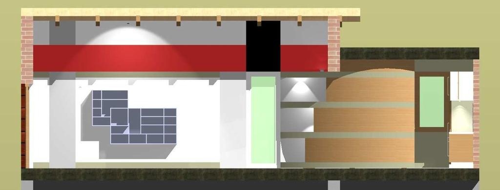
106 106 Learning Interior CadLine
THE BEGINNERS GUIDE TO ELITECAD. EliteCAD12AR. Messerli EliteCAD Version
 Messerli EliteCAD Version 12 25.06.2012 THE BEGINNERS GUIDE TO ELITECAD EliteCAD12AR Austria Messerli Informatik GmbH Hamoderstraße 4 4020 Linz info@messerli.at Tel: +43 732 341 574 CAD Hotline: +43 1
Kitchen and Bath Design Tutorial
 Kitchen and Bath Design Tutorial This tutorial continues where the Interior Design Tutorial left off. You should save this tutorial using a new name to archive your previous work. The tools and techniques
Kitchen and Bath Design Tutorial
 Kitchen and Bath Design Tutorial This tutorial continues where the Interior Design Tutorial left off. You should save this tutorial using a new name to archive your previous work. The tools and techniques
Advance Concrete. Tutorial
 Advance Concrete Tutorial Table of contents About this tutorial... 9 How to use this guide... 10 Lesson 1: Creating a building grid... 11 Step 1: Create a default building grid... 11 Step 2: Set the distances
House Design Tutorial
 House Design Tutorial This House Design Tutorial shows you how to get started on a design project. The tutorials that follow continue with the same plan. When you are finished, you will have created a
Getting Started. with Easy Blue Print
 Getting Started with Easy Blue Print User Interface Overview Easy Blue Print is a simple drawing program that will allow you to create professional-looking 2D floor plan drawings. This guide covers the
House Design Tutorial
 House Design Tutorial This House Design Tutorial shows you how to get started on a design project. The tutorials that follow continue with the same plan. When you are finished, you will have created a
Autodesk Medical Center
 Autodesk Medical Center Page 1 Contents Autodesk Medical Center... 1 Revit Projects... 3 Exercise 1 Create a new project file... 3 Datum Elements... 4 Exercise 2 Add Grids... 5 Exercise 3 Edit Levels...
Kitchen and Bath Design Tutorial
 Kitchen and Bath Design Tutorial This tutorial continues where the Interior Design Tutorial left off. You should save this tutorial using a new name to archive your previous work. The tools and techniques
Roof Tutorial Wall Specification
 Roof Tutorial The majority of Roof Tutorial describes some common roof styles that can be created using settings in the Wall Specification dialog and can be completed independent of the other tutorials.
Version 14 COURSE UNIT 5. Work Drawings
 Version 14 COURSE UNIT 5 Work Drawings Table of Contents Introduction... 2 Preparation... 3 Switch representation mode... 5 Parameter representation mode... 7 Change imaging depth... 10 Modify external
Appendix B: Autocad Booklet YR 9 REFERENCE BOOKLET ORTHOGRAPHIC PROJECTION
 Appendix B: Autocad Booklet YR 9 REFERENCE BOOKLET ORTHOGRAPHIC PROJECTION To load Autocad: AUTOCAD 2000 S DRAWING SCREEN Click the start button Click on Programs Click on technology Click Autocad 2000
Advance Steel. Tutorial
 Advance Steel Tutorial Table of contents About this tutorial... 7 How to use this guide...9 Lesson 1: Creating a building grid...10 Step 1: Creating an axis group in the X direction...10 Step 2: Creating
Drawing with precision
 Drawing with precision Welcome to Corel DESIGNER, a comprehensive vector-based drawing application for creating technical graphics. Precision is essential in creating technical graphics. This tutorial
ARCHICAD Introduction Tutorial
 Starting a New Project ARCHICAD Introduction Tutorial 1. Double-click the Archicad Icon from the desktop 2. Click on the Grey Warning/Information box when it appears on the screen. 3. Click on the Create
House Design Tutorial
 Chapter 2: House Design Tutorial This House Design Tutorial shows you how to get started on a design project. The tutorials that follow continue with the same plan. When we are finished, we will have created
House Design Tutorial
 Chapter 2: House Design Tutorial This House Design Tutorial shows you how to get started on a design project. The tutorials that follow continue with the same plan. When you are finished, you will have
Training CAD/ Part Designer: Designing with Angled Parts
 Training CAD/ Part Designer: Designing with Angled Parts We have attempted to keep the content of this document complete, accurate and under permanent review. However, due to the continuous development,
Kitchen and Bath Design Tutorial
 Adding Cabinets Chapter 5: Kitchen and Bath Design Tutorial This tutorial continues where the Materials Tutorial left off. You should save this tutorial using a new name to archive your previous work.
House Design Tutorial
 Chapter 2: House Design Tutorial This House Design Tutorial shows you how to get started on a design project. The tutorials that follow continue with the same plan. When you are finished, you will have
Existing and Design Profiles
 NOTES Module 09 Existing and Design Profiles In this module, you learn how to work with profiles in AutoCAD Civil 3D. You create and modify profiles and profile views, edit profile geometry, and use styles
CAD Tutorial. CAD Detail Windows. In this tutorial you ll learn about: CAD Detail Windows Exploding and Modifying a CAD Block
 CAD Tutorial In this tutorial you ll learn about: CAD Detail Windows Exploding and Modifying a CAD Block Creating a New CAD Block CAD Detail from View Creating a Plot Plan CAD Detail Windows CAD Details
COURSE UNIT 3. Plan Creation. Messerli EliteCAD Version
 Messerli EliteCAD Version 13 27.09.2013 COURSE UNIT 3 Plan Creation Switzerland: Austria: Germany: Messerli Informatik AG Messerli Informatik GmbH Messerli Informatik GmbH Pfadackerstrasse 6 Hamoderstraße
S206E Lecture 6, 5/18/2016, Rhino 3D Architectural Modeling an overview
 Copyright 2016, Chiu-Shui Chan. All Rights Reserved. S206E057 Spring 2016 This tutorial is to introduce a basic understanding on how to apply visual projection techniques of generating a 3D model based
Part 6: Checking an existing kitchen design
 Welcome, Thank you for choosing, an innovative surveying tool for kitchen surveying. To help you get started with, we will guide you on the following pages through the registration, installation and handling
SMALL OFFICE TUTORIAL
 SMALL OFFICE TUTORIAL in this lesson you will get a down and dirty overview of the functionality of Revit Architecture. The very basics of creating walls, doors, windows, roofs, annotations and dimensioning.
Getting Started with. Vectorworks Architect
 Getting Started with Vectorworks Architect Table of Contents Introduction...2 Section 1: Program Installation and Setup...6 Installing the Vectorworks Architect Program...6 Exercise 1: Launching the Program
AutoCAD LT 2012 Tutorial. Randy H. Shih Oregon Institute of Technology SDC PUBLICATIONS. Schroff Development Corporation
 AutoCAD LT 2012 Tutorial Randy H. Shih Oregon Institute of Technology SDC PUBLICATIONS www.sdcpublications.com Schroff Development Corporation AutoCAD LT 2012 Tutorial 1-1 Lesson 1 Geometric Construction
ACAD-BAU TUTORIAL For BricsCAD platform
 ACAD-BAU TUTORIAL WWW.ARHINOVA.SI For BricsCAD platform August 06 WORKSPACE ACAD-BAU RIBBON ACAD-BAU CONTROL BAR F ACAD-BAU PALETTES BASIC SETTINGS Use New command and open the template called ACB_International.DWT.
Learning Guide. ASR Automated Systems Research Inc. # Douglas Crescent, Langley, BC. V3A 4B6. Fax:
 Learning Guide ASR Automated Systems Research Inc. #1 20461 Douglas Crescent, Langley, BC. V3A 4B6 Toll free: 1-800-818-2051 e-mail: support@asrsoft.com Fax: 604-539-1334 www.asrsoft.com Copyright 1991-2013
AutoCAD 2D. Table of Contents. Lesson 1 Getting Started
 AutoCAD 2D Lesson 1 Getting Started Pre-reqs/Technical Skills Basic computer use Expectations Read lesson material Implement steps in software while reading through lesson material Complete quiz on Blackboard
Chief Architect New Feature List
 SYSTEM / PERFORMANCE Chief Architect Premier X4 is available in 64 bit and 32 bit versions. The 64 bit version is more efficient in managing memory and you will see better performance on larger plan files
ArchiCAD Easy Start. Ronald Brailsford. Find and double click on the ArchiCAD Icon on your desktop.
 ArchiCAD Easy Start Ronald Brailsford THE CABIN Start to Finish Chapter 1 Welcome to the world of BUILDING INFORMATION MODELING. BIM ArchiCAD was the first software to create the smart intelligent modeling
1. Creating geometry based on sketches 2. Using sketch lines as reference 3. Using sketches to drive changes in geometry
 4.1: Modeling 3D Modeling is a key process of getting your ideas from a concept to a read- for- manufacture state, making it core foundation of the product development process. In Fusion 360, there are
Module 1C: Adding Dovetail Seams to Curved Edges on A Flat Sheet-Metal Piece
 1 Module 1C: Adding Dovetail Seams to Curved Edges on A Flat Sheet-Metal Piece In this Module, we will explore the method of adding dovetail seams to curved edges such as the circumferential edge of a
imos Getting Started
 imos 12.0 - Getting Started June 2015 imos Aktiengesellschaft Planckstraße 24 D-32052 Herford Tel. +49(0)5221.976-0 Fax +49(0)5221.976-123 info@imos3d.com www.imos3d.com This document is provided just
with MultiMedia CD Randy H. Shih Jack Zecher SDC PUBLICATIONS Schroff Development Corporation
 with MultiMedia CD Randy H. Shih Jack Zecher SDC PUBLICATIONS Schroff Development Corporation WWW.SCHROFF.COM Lesson 1 Geometric Construction Basics AutoCAD LT 2002 Tutorial 1-1 1-2 AutoCAD LT 2002 Tutorial
2809 CAD TRAINING: Part 1 Sketching and Making 3D Parts. Contents
 Contents Getting Started... 2 Lesson 1:... 3 Lesson 2:... 13 Lesson 3:... 19 Lesson 4:... 23 Lesson 5:... 25 Final Project:... 28 Getting Started Get Autodesk Inventor Go to http://students.autodesk.com/
Embroidery Gatherings
 Planning Machine Embroidery Digitizing and Designs Floriani FTCU Digitizing Fill stitches with a hole Or Add a hole to a Filled stitch object Create a digitizing plan It may be helpful to print a photocopy
Floorplanner Editor Manual
 Editor Manual Floorplanner Editor Manual 1 Overview 2 Canvas a 2D view b View Settings 3 3D view a Orbital and walkthrough mode b How to navigate c Adding cameras d Scenery image e Create a render 4 Sidebar
Assignment 10 Revit CAD Fundamentals I Due March 29 Architecture 411
 Due March 29 Architecture 411 Objectives To learn the basic concepts involved with Building Information Modeling. To become familiar with basic operation of the Revit user interface. To learn techniques
SDC. AutoCAD LT 2007 Tutorial. Randy H. Shih. Schroff Development Corporation Oregon Institute of Technology
 AutoCAD LT 2007 Tutorial Randy H. Shih Oregon Institute of Technology SDC PUBLICATIONS Schroff Development Corporation www.schroff.com www.schroff-europe.com AutoCAD LT 2007 Tutorial 1-1 Lesson 1 Geometric
PRODIM CT 3.0 MANUAL the complete solution
 PRODIM CT 3.0 MANUAL the complete solution We measure it all! General information Copyright All rights reserved. Apart from the legally laid down exceptions, no part of this publication may be reproduced,
Training Guide 1 Basic Construction Overview. (v1.1)
") Training Guide 1 Basic Construction Overview (v1.1) Contents Training Guide 1 Basic Construction Overview... 1 Creating a new project... 3 Entering Measurements... 6 Adding the Walls... 10 Inserting Doors
Training Guide 1 Basic Construction Overview (v1.1) Contents Training Guide 1 Basic Construction Overview... 1 Creating a new project... 3 Entering Measurements... 6 Adding the Walls... 10 Inserting Doors
Part 8: The Front Cover
 Part 8: The Front Cover 4 Earpiece cuts and housing Lens cut and housing Microphone cut and housing The front cover is similar to the back cover in that it is a shelled protrusion with screw posts extruding
University Libraries ScanPro 3000 Microfilm Scanner
 University Libraries ScanPro 3000 Microfilm Scanner Help Guide Table of Contents Getting Started 3 Loading the Film 4-5 Viewing Your Film 6-7 Motorized Roll Film Control 6 Crop Box 7 Using the Toolbar
SolidWorks Part I - Basic Tools SDC. Includes. Parts, Assemblies and Drawings. Paul Tran CSWE, CSWI
 SolidWorks 2015 Part I - Basic Tools Includes CSWA Preparation Material Parts, Assemblies and Drawings Paul Tran CSWE, CSWI SDC PUBLICATIONS Better Textbooks. Lower Prices. www.sdcpublications.com Powered
Architecture 2012 Fundamentals
 Autodesk Revit Architecture 2012 Fundamentals Supplemental Files SDC PUBLICATIONS Schroff Development Corporation Better Textbooks. Lower Prices. www.sdcpublications.com Tutorial files on enclosed CD Visit
Floorplanner Drawing Manual
 Floorplanner Floorplanner Drawing Manual Drawing Manual Floorplanner lets you easily create interactive floorplans and publish them online. This manual explains the floorplanner drawing tool. For details
AutoCAD Tutorial First Level. 2D Fundamentals. Randy H. Shih SDC. Better Textbooks. Lower Prices.
 AutoCAD 2018 Tutorial First Level 2D Fundamentals Randy H. Shih SDC PUBLICATIONS Better Textbooks. Lower Prices. www.sdcpublications.com Powered by TCPDF (www.tcpdf.org) Visit the following websites to
Alibre Design Exercise Manual Introduction to Sheet Metal Design
 Alibre Design Exercise Manual Introduction to Sheet Metal Design Copyrights Information in this document is subject to change without notice. The software described in this documents is furnished under
Principles and Practice
 Principles and Practice An Integrated Approach to Engineering Graphics and AutoCAD 2011 Randy H. Shih Oregon Institute of Technology SDC PUBLICATIONS www.sdcpublications.com Schroff Development Corporation
AutoCAD LT 2009 Tutorial
 AutoCAD LT 2009 Tutorial Randy H. Shih Oregon Institute of Technology SDC PUBLICATIONS Schroff Development Corporation www.schroff.com Better Textbooks. Lower Prices. AutoCAD LT 2009 Tutorial 1-1 Lesson
ILLUSTRATOR BASICS FOR SCULPTURE STUDENTS. Vector Drawing for Planning, Patterns, CNC Milling, Laser Cutting, etc.
 ILLUSTRATOR BASICS FOR SCULPTURE STUDENTS Vector Drawing for Planning, Patterns, CNC Milling, Laser Cutting, etc. WELCOME TO THE ILLUSTRATOR TUTORIAL FOR SCULPTURE DUMMIES! This tutorial sets you up for
Module 2: Radial-Line Sheet-Metal 3D Modeling and 2D Pattern Development: Right Cone (Regular, Frustum, and Truncated)
") Inventor (5) Module 2: 2-1 Module 2: Radial-Line Sheet-Metal 3D Modeling and 2D Pattern Development: Right Cone (Regular, Frustum, and Truncated) In this tutorial, we will learn how to build a 3D model
Inventor (5) Module 2: 2-1 Module 2: Radial-Line Sheet-Metal 3D Modeling and 2D Pattern Development: Right Cone (Regular, Frustum, and Truncated) In this tutorial, we will learn how to build a 3D model
Module 1G: Creating a Circle-Based Cylindrical Sheet-metal Lateral Piece with an Overlaying Lateral Edge Seam And Dove-Tail Seams on the Top Edge
 Inventor (10) Module 1G: 1G- 1 Module 1G: Creating a Circle-Based Cylindrical Sheet-metal Lateral Piece with an Overlaying Lateral Edge Seam And Dove-Tail Seams on the Top Edge In Module 1A, we have explored
Chief Architect X3 Training Series. Layers and Layer Sets
 Chief Architect X3 Training Series Layers and Layer Sets Save time while creating more detailed plans Why do you need Layers? Setting up Layer Lets Adding items to layers Layers and Layout Pages Layer
Tas Engineering Training Workbook 1
 Tas Engineering Training Workbook 1 Tas 3D Modeller Tas Manager Your Tas Manager contains two main folders: a Tas folder and a Tas Data folder. See the directory-tree on the left-hand side above. If you
Relative Coordinates
 AutoCAD Essentials Most drawings are created using relative coordinates. This means that the next point is set from the last point drawn. The last point drawn is stored as temporary 0,0". AutoCAD uses
Introduction to Autodesk Inventor for F1 in Schools (Australian Version)
") Introduction to Autodesk Inventor for F1 in Schools (Australian Version) F1 in Schools race car In this course you will be introduced to Autodesk Inventor, which is the centerpiece of Autodesk s Digital
Introduction to Autodesk Inventor for F1 in Schools (Australian Version) F1 in Schools race car In this course you will be introduced to Autodesk Inventor, which is the centerpiece of Autodesk s Digital
Constructing a Wedge Die
 1-(800) 877-2745 www.ashlar-vellum.com Using Graphite TM Copyright 2008 Ashlar Incorporated. All rights reserved. C6CAWD0809. Ashlar-Vellum Graphite This exercise introduces the third dimension. Discover
Walls. Section. Walls. When you finish this section, you should understand the following:
 GOLDMC03_132283433X 8/24/06 2:23 PM Page 123 Section 3 Walls When you finish this section, you should understand the following: How to place a wall object. How to change walls by dynamically pulling on
Activity 1 Modeling a Plastic Part
 Activity 1 Modeling a Plastic Part In this activity, you will model a plastic part. When completed, your plastic part should look like the following two illustrations. While building this model, take time
Using Dynamic Views. Module Overview. Module Prerequisites. Module Objectives
 Using Dynamic Views Module Overview The term dynamic views refers to a method of composing drawings that is a new approach to managing projects. Dynamic views can help you to: automate sheet creation;
Lesson 6 2D Sketch Panel Tools
 Lesson 6 2D Sketch Panel Tools Inventor s Sketch Tool Bar contains tools for creating the basic geometry to create features and parts. On the surface, the Geometry tools look fairly standard: line, circle,
Introduction to CATIA V5
 Introduction to CATIA V5 Release 17 (A Hands-On Tutorial Approach) Kirstie Plantenberg University of Detroit Mercy SDC PUBLICATIONS Schroff Development Corporation www.schroff.com Better Textbooks. Lower
Deck Tutorial. Chapter 8: Decks and Porches
 Decks and Porches Chapter 8: Deck Tutorial Now we ll continue where the Landscaping Tutorial left off and create a deck off the back of the house, connecting it to the terrain with an exterior staircase.
Ribbon (Panels) + Options Bar + Contextual Tabs (tools based on selection)
 + Options Bar + Contextual Tabs (tools based on selection)") Week 11 Revit, Basics Building Information Modeling (BIM) - Parametric 3D Model File Types: Projects RVT (template = RTE) Families - RFA (template = RFT), "Symbols" Layout Workspace - Elevation Markers
Week 11 Revit, Basics Building Information Modeling (BIM) - Parametric 3D Model File Types: Projects RVT (template = RTE) Families - RFA (template = RFT), "Symbols" Layout Workspace - Elevation Markers
Symbols and Standards (Architectural CAD)
") Design and Drafting Description In this activity the teacher will give an orientation to the symbols and conventions of Architectural CAD. Industry common symbols are used for most of the fixtures and
Design and Drafting Description In this activity the teacher will give an orientation to the symbols and conventions of Architectural CAD. Industry common symbols are used for most of the fixtures and
Evaluation Chapter by CADArtifex
 The premium provider of learning products and solutions www.cadartifex.com EVALUATION CHAPTER 2 Drawing Sketches with SOLIDWORKS In this chapter: Invoking the Part Modeling Environment Invoking the Sketching
SolidWorks Tutorial 1. Axis
 SolidWorks Tutorial 1 Axis Axis This first exercise provides an introduction to SolidWorks software. First, we will design and draw a simple part: an axis with different diameters. You will learn how to
Deck Tutorial. Chapter 6: Decks and Porches
 Chapter 6: Deck Tutorial Now we ll continue where the Landscaping Tutorial left off and create a deck off the back of the house, connecting it to the terrain with an exterior staircase. You may want to
Module 1H: Creating an Ellipse-Based Cylindrical Sheet-metal Lateral Piece
 Inventor (10) Module 1H: 1H- 1 Module 1H: Creating an Ellipse-Based Cylindrical Sheet-metal Lateral Piece In this Module, we will learn how to create an ellipse-based cylindrical sheetmetal lateral piece
Revit Structure 2013 Basics
 Revit Structure 2013 Basics Framing and Documentation Elise Moss Supplemental Files SDC P U B L I C AT I O N S Schroff Development Corporation Better Textbooks. Lower Prices. www.sdcpublications.com Tutorial
Sketch-Up Guide for Woodworkers
 W Enjoy this selection from Sketch-Up Guide for Woodworkers In just seconds, you can enjoy this ebook of Sketch-Up Guide for Woodworkers. SketchUp Guide for BUY NOW! Google See how our magazine makes you
Deck Tutorial. Chapter 8: Decks and Porches
 Chapter 8: Deck Tutorial Now we ll continue where the Landscaping Tutorial left off and create a deck off the back of the house, connecting it to the terrain with an exterior staircase. You may want to
EG1003 Help and How To s: Revit Tutorial
 EG1003 Help and How To s: Revit Tutorial Completion of this tutorial is required for Milestone 1. Include screenshots of it in your Milestone 1 presentation. Downloading Revit: Before beginning the tutorial,
Key Terms. Where is it Located Start > All Programs > Adobe Design Premium CS5> Adobe Photoshop CS5. Description
 Adobe Adobe Creative Suite (CS) is collection of video editing, graphic design, and web developing applications made by Adobe Systems. It includes Photoshop, InDesign, and Acrobat among other programs.
Module 1E: Parallel-Line Flat Pattern Development of Sheet- Metal Folded Model Wrapping the 3D Space of An Oblique Circular Cylinder
 Inventor (10) Module 1E: 1E- 1 Module 1E: Parallel-Line Flat Pattern Development of Sheet- Metal Folded Model Wrapping the 3D Space of An Oblique Circular Cylinder In this Module, we will explore the topic
AutoCAD Civil 3D 2009 ESSENTIALS
 AutoCAD Civil 3D 2009 ESSENTIALS SDC PUBLICATIONS Schroff Development Corporation www.schroff.com Better Textbooks. Lower Prices. Alignments and Profiles Section 2: Profiles In this section you learn how
Toothbrush Holder. A drawing of the sheet metal part will also be created.
 Prerequisite Knowledge Previous knowledge of the following commands is required to complete this lesson; Sketch (Line, Centerline, Circle, Add Relations, Smart Dimension,), Extrude Boss/Base, and Edit
Autodesk Advance Steel. Drawing Style Manager s guide
 Autodesk Advance Steel Drawing Style Manager s guide TABLE OF CONTENTS Chapter 1 Introduction... 5 Details and Detail Views... 6 Drawing Styles... 6 Drawing Style Manager... 8 Accessing the Drawing Style
1. Create a 2D sketch 2. Create geometry in a sketch 3. Use constraints to position geometry 4. Use dimensions to set the size of geometry
 2.1: Sketching Many features that you create in Fusion 360 start with a 2D sketch. In order to create intelligent and predictable designs, a good understanding of how to create sketches and how to apply
AutoCAD Lab 1 Basics and Drawing Fundamentals. EGS 1007 Engineering Concepts and Methods
 AutoCAD Lab 1 Basics and Drawing Fundamentals EGS 1007 Engineering Concepts and Methods Will the Computer Ever REPLACE Pencil and Paper Drawings? Maybe someday When a computer becomes as light, small,
Drawing 8e CAD#11: View Tutorial 8e: Circles, Arcs, Ellipses, Rotate, Explode, & More Dimensions Objective: Design a wing of the Guggenheim Museum.
 Page 1 of 6 Introduction The drawing used for this tutorial comes from Clark R. and M.Pause, "Precedents in Architecture", VNR 1985, page 135. Stephen Peter of the University of South Wales developed the
Rhinoceros modeling tools for designers. Using Layouts in Rhino 5
 Rhinoceros modeling tools for designers Using Layouts in Rhino 5 RH50-TM-LAY-Apr-2014 Rhinoceros v5.0, Layouts, Training Manual Revised April 8, 2014, Mary Fugier mary@mcneel.com Q&A April 8, 2014, Lambertus
User Guide V10 SP1 Addendum
 Alibre Design User Guide V10 SP1 Addendum Copyrights Information in this document is subject to change without notice. The software described in this document is furnished under a license agreement or
Revit Structure 2014 Basics
 Revit Structure 2014 Basics Framing and Documentation Elise Moss Authorized Author SDC P U B L I C AT I O N S Better Textbooks. Lower Prices. www.sdcpublications.com Powered by TCPDF (www.tcpdf.org) Visit
Dean Muccio AutoCAD Interior Designer. for the. AutoCAD for Mac and PC SDC. Better Textbooks. Lower Prices.
 Dean Muccio AutoCAD 2020 for the Interior Designer AutoCAD for Mac and PC SDC P U B L I C AT I O N S Better Textbooks. Lower Prices. www.sdcpublications.com Powered by TCPDF (www.tcpdf.org) Visit the following
Beginner s Guide to SolidWorks Alejandro Reyes, MSME Certified SolidWorks Professional and Instructor SDC PUBLICATIONS
 Beginner s Guide to SolidWorks 2008 Alejandro Reyes, MSME Certified SolidWorks Professional and Instructor SDC PUBLICATIONS Schroff Development Corporation www.schroff.com www.schroff-europe.com Part Modeling
Table of Contents. Lesson 1 Getting Started
 NX Lesson 1 Getting Started Pre-reqs/Technical Skills Basic computer use Expectations Read lesson material Implement steps in software while reading through lesson material Complete quiz on Blackboard
Advance Steel. Drawing Style Manager s guide
 Advance Steel Drawing Style Manager s guide TABLE OF CONTENTS Chapter 1 Introduction...7 Details and Detail Views...8 Drawing Styles...8 Drawing Style Manager...9 Accessing the Drawing Style Manager...9
ISCapture User Guide. advanced CCD imaging. Opticstar
 advanced CCD imaging Opticstar I We always check the accuracy of the information in our promotional material. However, due to the continuous process of product development and improvement it is possible
BIM - ARCHITECTUAL IMPORTING A SCANNED PLAN
 BIM - ARCHITECTUAL IMPORTING A SCANNED PLAN INTRODUCTION In this section, we will demonstrate importing a plan created in another application. One of the most common starting points for a project is from
Dean Muccio. AutoCAD 2018 for the. Interior Designer. AutoCAD for Mac and PC SDC. Better Textbooks. Lower Prices.
 Dean Muccio AutoCAD 2018 for the Interior Designer AutoCAD for Mac and PC SDC P U B L I C AT I O N S Better Textbooks. Lower Prices. www.sdcpublications.com Powered by TCPDF (www.tcpdf.org) Visit the following
CONTENTS CHAPTER 1 WHAT THIS IS ALL ABOUT...
 CONTENTS CHAPTER 1 WHAT THIS IS ALL ABOUT... 17 INTRODUCTION... 17 Terminology... 18 MACINTOSH AND WINDOWS... 20 CONVENTIONS USED IN THIS TUTORIAL... 21 Command Menu Title And Pull-Down Menu... 22 Commands,
ARCHITECT VECTORWORKS EIGHTH EDITION TUTORIAL MANUAL BY JONATHAN PICKUP
 CH EIGHTH EDITION TUTORIAL MANUAL BY JONATHAN PICKUP A M TO R I A L T TU EC IT UA L AR ARCHITECT N HTH EDITION EIG / / / / / / / / / / / / / / / / / / / / / / / / / / / / / / / / / / / / / / / / / / /