LD20558-L Parking Lots with AutoCAD Civil 3D Corridors
|
|
|
- Ralf Golden
- 5 years ago
- Views:
Transcription
1 LD20558-L Parking Lots with AutoCAD Civil 3D Corridors Steven Hill CAD Manager, Civil Designer / Geosyntec Consultants.NET Application Developer / Red Transit Consultants, LLC Learning Objectives Discover the Corridor enhancements of AutoCAD Civil 3D 2017 Learn the steps and workflow involved in modeling a parking lot using feature lines, surfaces, and corridors See a live example of a parking lot with Corridors Get excited about this great new feature in AutoCAD Civil 3D Description Learn the key steps and workflows involved in designing a parking lot with AutoCAD Civil 3D 2017 software s new enhancement Corridors from Feature Lines. As long as AutoCAD Civil 3D software has been available, parking lot grading has been difficult to model and obtain full quantities, sub surfaces, and so on. With the new enhancements of AutoCAD Civil 3D 2017 software, we gain a huge step forward in modeling our nonlinear grading areas. This class will go through the necessary steps, workflows, and techniques involved in obtaining a fully modeled parking lot utilizing AutoCAD Civil 3D 2017 software s Corridors. Your AU Expert(s) Steve Hill is an Autodesk AutoCAD / AutoCAD Civil3D Certified Professional who has sixteen years of professional experience in Autodesk products and site civil design with an array of project types including subdivision design, road reconstructions, streetscapes, shopping centers, rail spurs, natural gas wells/pipelines, and landfill design. His project design experience includes various stages from overall planning to the detailed construction including site design, site grading, complex volume calculations, utility and pond sizing, soil erosion control measures, and details. Hill also maintains a strong background in computers and resolving issues on multiple operating platforms. With his LLC, Red Transit Consultants, he is passionate about developing applications and workflow management tools for AutoCAD, Civil 3D, and Map 3D as well as small Windows stand-alone applications with various programming languages. Page 1


2 Background and Summary Prior to AU 2016 It is recommended that you have a strong understanding of AutoCAD Civil 3D Corridors prior to coming to this lab session. The workflows and software features explained throughout this handout and during the lab session will be at an advanced level of corridor usage. We will be utilizing Assemblies that function similar to curb return Assemblies utilized in AutoCAD Civil 3D Corridor Intersections. The Assemblies will be added to various Regions of the Corridor model and will target horizontal and vertical offset Feature lines. The Corridor model will have multiple baselines with many regions and targets, thus full working knowledge of Corridor modeling will be highly beneficial. However, please do not allow this to turn you away from taking the class at this time there will be information presented in the class in which will help further your understanding. Data Sets Data sets will be available on the day of the lab session and will be posted on the AU website after the conference. The data set files provided with this handout correspond to the task items listed. You may either choose to work through each task from the beginning, or skip directly to a specific task with the previous tasks completed. AutoCAD Civil 3D Parking Lot Modeling Prior to AutoCAD Civil 3D 2017 Corridor Enhancements Before getting into the details of this class, it is important to understand the prior workflows of Parking Lot Modeling within AutoCAD Civil 3D. As a refresher, I recommend Eric Chappell s Autodesk University 2013 class called Ten Practically Awesome Grading Examples (CP2975- P). He has given this class in some form for numerous years and much of what he has taught can still be applied with the workflows for AutoCAD Civil 3D 2017 outlined here. However, one key component with the prior workflows is that curb and gutter and pavements could not be truly modeled; the new Corridor enhancements of AutoCAD Civil 3D 2017 allow us to do that. Prior methods involved developing a surface for your final pavement grades, then once final, returning to model curb and gutter around islands by draping a feature line representing the pavement edge of the curb onto the design surface and performing Stepped Offsets to model the gutter and top of curb. This workflow helped to develop a surface that represented the design pavement and curb and gutter surface. PARKING LOT CURB AND GUTTER STEPPED OFFSET WORKFLOW (IMAGES TAKEN FROM AUTODESK UNIVERSITY CP2975-P: TEN PRACTICALLY AWESOME GRADING EXAMPLES) Page 2


3 AutoCAD Civil 3D 2017 Corridor Enhancements Below is a list of the enhancements listed on the Autodesk AutoCAD Civil 3D website we will see in this class that allows us to utilize the outlined workflow to model Parking Lots with Corridors: Feature Line as Corridor baseline In addition to alignments and profiles, feature lines can be used as corridor baselines. Feature lines can also be selected when creating the corridor and when adding baselines. Property data to corridor solids - Enhancements to Corridor Solid extraction now enables the automatic association of property data and the ability to have corridor solids remain dynamic to changes in the corridor. The result is that corridor solids can now include information such as material, classification code, volumes and more. This can then be used throughout the design workflow, including: design making and construction planning. Corner cleanup for corridors - Where corridor tangents intersect at a corner, and where the corridor is created at a fixed width, the inner and outer corners of corridors are cleaned up automatically to improve modeling efficiency and accuracy. Please be sure to read up about how corner cleanup for corridors works on the AutoCAD Civil 3D 2017 Help Page there are specific instances where it applies and does not apply. CORRIDOR CLEANUP EXAMPLES (IMAGES TAKEN FROM THE AUTOCAD CIVIL 3D 2017 HELP PAGE) Extract corridor Feature Line workflow - Extract multiple feature lines from within corridor regions or closed polygonal areas. Use name template options to add corridor-related properties to the feature line names. Page 3

4 Summary of Benefits when Using a Corridor for a Parking Lot True BIM capabilities Potentially faster grading revisions Grading edits are easier when required to swap out items like curb sizes, or adjusting pavement thicknesses late in design Profiling of all surfaces within the Corridor Projecting Corridor solids to sections Extracting AutoCAD Solids from the Corridor The ability to use Civil 3D s QTO feature and assign pay items to the various components of the Corridor Better visualization graphic processing utilizing both corridor and surfaces for products like Navisworks, Infraworks 360, or 3ds Max Workflow Overview To model a parking lot with a Corridor, we will be placing a Feature Line at the edge of pavement line for every curb. In doing this, each curb Baseline will have several Regions within the Corridor to define it. It is important to realize that Corridor samples are taken perpendicular to the Region s Baseline. This will be critical in understanding how to develop the model. Below is the basic outline of the workflow: 1. Develop parking lot design. Prepare drawing with existing surface, parking lot line work, and any access roads leading into site. For any adjacent roads to the parking lot area, it is recommended to have a Corridor model developed along the roadway to allow for targeting within the parking lot Corridor model. 2. Establish a Feature line grid over top of your parking lot to establish a temporary design grade to use for establishing curb elevations. Ensure that the elevations used in the grid include critical points like high and low points through the parking lot. 3. Setup the curb Assembly. The Curb Return Fillets Assembly used with the Civil 3D Intersection Wizard will be used for this example. CURB RETURN FILLETS ASSEMBLY Page 4


5 4. Ensure all central curbed islands have four different feature lines to target. The thin red line in the image below represents the baseline that will be added to a Corridor, the thick red line represents targets, and the hatched gray area represents a region. (2 Center of Drive Isles Feature Lines and 2 Center of Parking Bay Feature Lines) CENTRAL CURBED ISLAND EXAMPLE 5. Border parking bays will be modeled different than central curbed islands. With these, we will need to add an additional feature line coming from the corner of the parking bay out to the drive isle. This needs to be done because the new Corridor cleanup functionality does not work with horizontal / vertical offset targets. It is recommended that the angle of this line be a bisecting angle to the angle of the parking, but it is not required and will be dependent upon critical temporary design surface points. Like the central curbed islands, the thin red line represents the baseline that will be added to the Corridor, the thick red lines represent targets, and the hatched colored areas represent at least one region each. BORDER PARKING BAYS 6. Assign curb elevations from the temporary base design surface. 7. Create a Corridor and add each of the curb Feature Lines as baselines. Regions will use the Curb Return Fillets Assembly and targets will project to the items discussed previous. 8. Final Corridor cleanups and adjustments (i.e.: splitting regions, targets, etc. for better build). Page 5
6 Task 1 Model a Parking Lot with AutoCAD Civil 3D Corridors Pre-Task Feature Line Grid Explanation 1. Within the lab dataset, locate the drawing Pre-Task.dwg. The intent of this task is to provide an explanation of how the grid lines, shown in Task 1A, are established. 2. Locate the two 3D Polylines at the west and south areas of the parking lot. 3. Convert the 3D Polylines to Feature Lines. Use the Feature Line Editor to change elevations and grades as desired. The goal here is to develop a Feature Line grid with the elevations/grades for the pavement of the parking lot. Make sure these two Feature Lines address the following: a. Where the Feature Line crosses a Corridor, add a PI point to the Feature Line at the edge of asphalt and apply elevations at points that fall on the road surfaces, this will help control the road grades. b. Add grid Feature Lines at each center of drive isles. c. Add grid Feature Lines at each center of every parking bay. d. Elevations should only represent pavement elevations; ignore all curb. e. Establish high and low points across the surface. f. Note that these Feature Lines do not have to be the only Feature Lines used to define the pavement elevations/grades. Additional Feature Lines may be used; however, these Feature Lines will be used to model the Corridor. 4. Use the Stepped Offset command to offset the north-south Feature Line 60.0 feet to the east to the next drive isle centerline and apply the elevation adjustment as desired. Repeat across the parking lot. 5. Use the Stepped Offset command to offset the east-west Feature Line 54.5 feet to the north to the center of island, again applying the elevation adjustment as desired. Repeat across the parking lot to locate center of bays and center of islands. Task 1A Develop Temporary Design Base Grade Surface 1. Within the lab dataset, locate the drawing Task 1A.dwg. 2. Create a Tin surface called Temp Design Base Grade ; set the Style to Contours 1 and Create a Site called Temp Design Base Grade. 4. Create a Feature Line grid across the parking lot as outlined in the pre-task above. In an effort to achieve consistent results for this example, 3D Polylines are already placed in the Task 1A drawing. These can be converted to Feature Lines and maintain their elevations and items 4A-4E below can be ignored. Place the feature lines in the Temp Design Base Grade Site; set the Style to Basic Feature Line. 5. Add the Feature Lines to the Temp Design Base Grade Surface. Verify that the surface appears is created correctly. Edit Feature Lines elevations if necessary. Workflow Tip: You may desire to establish a couple of Feature Line grades and then perform a stepped offset to construct the grid. Alternatively, you may establish the grid, set a couple of Feature Line grades and then use the Set Adjacent Elevations tool. Page 6


7 FEATURE LINE GRID WITH TEMP DESIGN BASE GRADE SURFACE Task 1B Establish Projection Feature Lines 1. Continue working with the same drawing from Task 1A or within the lab dataset, locate the drawing Task 1B.dwg. 2. Create a Site called Projection Feature Lines. 3. Locate any abrupt angular changes on curb lines. These would be any corners that do not have a curve linking the two tangent lines. 4. Draw a line from the corner inwards to the parking lot towards the drive isle. It is recommended, but not required to draw the line as a bisecting angle to the angle of the parking space (i.e.: 90-degree parking spaces would have 45-degree projection line). Extend these lines to the drive isle feature line. 90 DEGREE BAY PROJECTION FEATURE LINES Page 7


8 5. Create a Feature Line from each of these projection lines and establish their elevations/grades from the Temp Design Base Grade Surface do not check set intermediate grade breaks. Place the Feature Line in the Projection Feature Lines Site and assign the Style Lane Slope Break. 6. For small parking bays, these projection lines can intersect at the drive isle line, but do not allow these projection lines to cross each other or cross the grid Feature Lines. SMALL PARKING BAY EXAMPLE 7. Repeat this process for all abrupt angular changes on curb lines. For angled and curved parking spaces, Projection Feature Lines should be done similarly. ANGLED AND CURVE PARKING PROJECT FEATURE LINES Task 1C Establish Curb Feature Lines 1. Continue working with the same drawing from Task 1B or within the lab dataset, locate the drawing Task 1C.dwg. 2. Create a Site called Baseline Feature Lines. 3. Locate a curb line within the parking lot. With the line that defines the edge of the curb adjacent to the pavement, create a Feature Line and establish its elevations/grades from the Temp Design Base Grade Surface do not check set intermediate grade breaks. Place the Feature Line in the Baseline Feature Lines Site using the Style Curb Line. Page 8


9 BASELINE FEATURE LINES 4. Repeat this process for all curb within the parking lot. Workflow Tip: If all of your asphalt lines are on the same layer, you can isolate that layer with the LAYISO command and use Create Feature Line from Objects command selecting all asphalt lines in turn creating Feature Lines with the desired Site, Style, and elevations from surface all at once. Page 9


10 Task 1D Create the Assembly 1. Continue working with the same drawing from Task 1C or within the lab dataset, locate the drawing Task 1D.dwg. 2. Open the Civil 3D Tool Palette and locate the Assemblies Imperial tab. 3. Find the Assembly called Curb Return Fillets, select it and place in your drawing. 4. The curb Subassembly by default is set to a wider curb than we are using for this project. Select the curb Subassembly, right click and select Subassembly Properties, Parameters tab and modify Dimension B to 12 and Dimension E to Note which side of the Assembly line the curb and pavement are on. By default when placing, curb is on the right and pavement is on the left. NOTE: If desired, rather than selecting a pre-built Assembly with Subassemblies already provided, you may create your own Assembly by selecting Subassemblies and attaching. However, the selected pavement Subassembly must allow for horizontal and vertical offset targeting for parking lot Corridor modeling methods explained in this handout, the Subassembly help button can provide this information. SUBASSEMBLY HELP Task 1E Create Corridor and Add Curb Interior Island Baselines 1. Continue working with the same drawing from Task 1D or within the lab dataset, locate the drawing Task 1E.dwg. 2. Turn Temp surface to No Display. 3. Create a Corridor and name it Final Parking Lot Grading. a. Select Baseline type: Feature Line. b. Next to the Feature Line selection pull down, select the pick button and select one of the parking lot island Feature Lines; you will need to name the Feature Line to proceed. c. Select Assembly: Curb Return Fillets. d. Do not select a surface target at this time. Page 10


11 e. Leave set baseline and region parameters checked. f. Select ok to create the initial build of the Corridor. g. Next will open a dialog called Baseline and Region Parameters. Set the overall frequency to 10 on tangents, Along Curve to Both, Curve Increment to 5, and Mid-ordinate distance to CORRIDOR FREQUENCY SETTINGS h. Select Ok and Rebuild the Corridor. 4. Observe the result of the built Corridor to verify it applied the Assembly correctly. If the result appears like shown below, it is likely that the Feature Line is going the wrong direction to apply the Curb Fillet Assembly with the curb on the right and the pavement on the left. a. Select the Feature Line, and then from the contextual ribbon, use the ReverseFeature command from the Edit Geometry Panel. b. Rebuild the Corridor. FEATURE LINE NEEDS TO BE REVERSED Page 11

12 CORRECTED FEATURE LINE DIRECTION 5. Next we need to establish targets for the Region. Targets will be like the red lines in example image below. a. Select the Corridor, from the contextual ribbon, select Edit Targets, pick inside the region to edit. b. For Horizontal Width or Offset Targets, pick in the Object Name column where <None> is shown. Change the pull down from Alignments to Feature Lines. Select the four nearest Temp Design Base Grade Feature Lines surrounding the island. Naming the Feature Lines is not required, but may be beneficial. c. Leave the Selection choice if multiple targets are found pull down set to Target to Nearest Offset. d. Repeat the exact same steps for the Vertical Slope or Elevation Targets. e. Ok through dialogs, allow the Corridor to rebuild. CURB ISLAND TARGET FEATURE LINES 6. To repeat for other interior islands, select the Corridor and enter Corridor Properties. On the Parameters tab, select Add Baseline and select the next Feature Line. Once added, in the Parameters Tree View, right click on the newly added baseline and select Add Region. Choose the Curb Return Fillets Assembly and click ok. There are several methods to adding baselines and setting targets in the Corridor. Repeat the process of adding baselines and regions and setting targets for all interior islands. 7. Corridor Frequencies, if not set in your template, must be done for each baseline added to the Corridor. Thus, once all islands are complete, open up Corridor Properties, Parameters tab, and select the button at the top: Set All Frequencies to the previously mentioned settings on Task 1E: Item 3: Letter G. Page 12


13 PROJECTED ISLAND CORRIDOR REGION 8. Create Corridor Surface of Final Grades. On the Surfaces tab, create the Corridor surface and add data to the surface. It is recommended for this complex Corridor to use the Feature Lines as opposed to using only the top code as it seems to get a better surface build. Lastly, on the Surface, make sure Overhang Corrections is set to Top Links. CORRIDOR SURFACE BUILD SETTINGS Workflow Tip: For a Corridor this complex, it is recommended but not required, to name each baseline related to what it is. This takes a bit more time initially, but can be very helpful in making modifications or troubleshooting issues. Page 13


14 CORRIDOR BASELINE NAMING Page 14

15 Task 1F Curb Exterior Island Baselines 1. Continue working with the same drawing from Task 1E or within the lab dataset, locate the drawing Task 1F.dwg. 2. Prior to adding in the exterior island baselines, we need to make some edits to the surrounding road Corridors. a. Main Road Design Corridor i. Locate the Main Road Full Section Assembly. ii. Copy the Assembly and Subassemblies. iii. Rename the copy to Main Road Half Section Left. iv. Delete the right half of the Assembly. v. On the Main Road Corridor, select the Corridor and notice that it has already been split into three regions. Go to Corridor Properties. vi. Change the second region (approximate stations ) to use the Main Road Half Section Left Assembly. vii. Select Ok and let the Corridor rebuild. b. Boundary Road Corridor i. Locate the Boundary Road Full Section Assembly. ii. Copy the Assembly and Subassemblies. iii. Rename the copy to Boundary Road Half Section Right. iv. Delete the left half of the Assembly. v. On the Boundary Road Corridor, select the Corridor, and notice that it has already been split into three regions. Go to Corridor Properties. vi. Change the second region (approximate stations ) to use the Boundary Road Half Section Right Assembly. vii. Select Ok and let the Corridor rebuild. 3. Add one of the curb exterior islands as a Baseline to the parking lot Corridor. Use the Curb Return Fillets Assembly. Select Ok and allow the Corridor to rebuild. 4. You may find that you need to reverse the direction of the feature lines here as well. Reverse and rebuild as necessary. 5. While building this Corridor, I found it was better to split the exterior islands up into two regions to limit the targets applied to the regions. The split will need to occur at the cyan colored lines shown in the image below. 6. Edit the Targets for the newly added Regions. Targets for the larger region will be three of the Temp Design Base Grade Feature Lines shown in red below. The smaller region will target the adjacent road centerline Alignment and Design Profile shown in green below. CURB EXTERIOR ISLAND BASELINE TARGETS Page 15

16 7. Repeat for all curb exterior islands. 8. Remember when complete, to go into Corridor Properties and Set All Frequencies to the previously mentioned settings on Task 1E: Item 3: Letter G. Workflow Tip: You can speed up the task of having to modify the Corridor frequencies to the desired values each time regions are added to the corridor by modifying the Corridor command settings. Even though the drawing is set to Save Command Settings as you work, these frequency adjustments do not get saved to the commands. To edit: Open Toolspace, Settings Tab, scroll to Corridors, Commands. Within the Create Corridor and Create Simple Corridor commands, right click and Edit Command Settings. Expand the item Assembly Insertion Defaults. This provides the default settings for Corridor frequencies. Edit the settings here and choose ok. Note: This change is per drawing; if you have desired settings you like, perform these settings in your templates. CORRIDOR COMMAND FREQUENCY DEFAULT SETTINGS Page 16


17 Task 1G Boundary Curb Baseline 1. Continue working with the same drawing from Task 1F or within the lab dataset, locate the drawing Task 1G.dwg. 2. Add the western most boundary curb Feature Line as a Baseline to the parking lot Corridor. Use the Curb Return Fillets Assembly and if necessary, reverse the Feature Line Direction. 3. Next, we need to perform Split Region several times along this Baseline. Split Regions should occur at the following locations: a. End of curb returns where the Region is adjacent to another Corridor Region. b. At Each Projection Feature Line c. Depending on how it builds you may need to split where you change targets within the region (i.e.: abrupt angular changes in red lines below). 4. Delete the region on the western side of the boundary Baseline as it is not needed we have a Corridor defining the surround road. 6. Assign Targets for each Region along the Baseline. Target examples are shown in the images below red lines are targets for the regions. BASELINE TARGETS FOR REGIONS ALONG THE BOUNDARY CURB Page 17


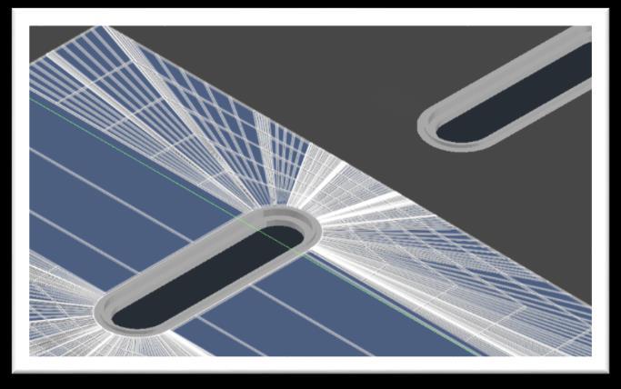
18 7. Once all the Targets are set, rebuild the Corridor. 8. Pan along the Corridor Baseline and look for any projection holes like shown below. These are caused by not sampling with tight enough frequency or you may need to add a frequency manually at a specific station. Tip: If the frequency does not fix the problem, you may need to split these regions once more and select the intersection of the two feature lines. This will force a sample to occur at the intersection. Then adjust the targets within each region to only include the targets for that region as when you split a region with assigned targets, both regions maintain the previously assigned targets. CORRIDOR PROJECTION HOLES 9. Repeat the above workflow for the other two boundary curb Feature Lines. 10. Be sure to Set All Frequencies to the previously mentioned settings on Task 1E: Item 3: Letter G and rebuild when completed. 11. The final Corridor and final surface should now be complete. There may be some areas that need some slight cleanup. At the end of this document there are additional tips and known issues that can assist with this tedious task. EXAMPLE OF FINAL Page 18


19 Task 2 Create Additional Surfaces from the Corridor With Corridors we can create surfaces of every layer! CORRIDOR SURFACES Task 3 Create Profile and Section Through Parking Lot With the ability of modeling a parking lot as a Corridor we can profile all the layers if we desire. PROFILE THROUGH THE CORRIDOR SURFACES SECTIONS THROUGH THE CORRIDOR Page 19


20 Task 4 Create Solid From the Corridor Civil 3D 2017 includes a new feature Creating a solid from a Corridor. Click on the Corridor and from the contextual ribbon select Extract Corridor Solids. The command gives the ability to extract solids by Station Range, within a Polygon, or All Regions. It will then break down the extraction by region and subassemblies used in the region placing each on its own layer with a corresponding layer template. Properties about the region can also be extracted to the solid. EXTRACT CORRIDOR SOLIDS EXTRACTION SETTINGS Page 20


21 EXTRACTED CORRIDOR SOLIDS Page 21
22 Workflow Tips Select Similar Select similar can be very helpful through this process by quickly allow you to select similar objects. Select an object, right click, and select similar at the bottom of right click menu. Isolate Objects / End object Isolation Object isolation works similarly to layer isolation, except it can be far more powerful within Civil 3D. Civil 3D objects consist of styles with many layers, thus layer isolation is not as helpful. With object isolation, you can achieve similar results. Select objects, right click, Isolate Objects, and select Isolate selected objects only those objects will then be displayed. To end, select any object, right click, Isolate Objects, and end isolation. When confused with Corridor Look at Parameters tab, locate baseline, and look at stationing! Note the overall baseline stationing and the region stationing also note that if zoomed to the extents of your corridor, as baseline or regions are selected, they are highlighted in your drawing. With the above in mind, you can also pan/zoom directly to any Corridor component from the Parameters tab. This can also be done from Toolspace by expanding the Corridor object. The Corridor Parameter buttons, collapse and expand are your friend. Use them will make scrolling through complex Corridors much faster. When editing a Corridor, from the Parameters tab, you can check and uncheck regions of the Corridor that get built. This helps to isolate the build down to the area of interest. Contextual Ribbon has most of the commands available that can be accessed through dialogs. Click an object and look at the ribbon change. The command you need might be right in front of your face saving several clicks through dialogs. Closed Feature Lines make the Corridor Selection a bit wonky. If you don t need the full length of the Feature Line to define the Corridor, you re probably better off trimming or breaking the Feature Line up into several Feature Lines. Adjusting the start/end location of closed Feature Lines prior to adding to the Corridor could help save time by creating fewer regions. When placing projection Feature Lines, make sure to pay attention to Temp Surface High and Low points. There were numerous times I overlooked this and had a projection line connecting to a drive isle and went right by a low point where there would be a drainage structure. This caused some odd behaviors in the Corridor build. Revised the projection line to the low point and it solved the issue. Page 22


23 Known Issues / Solutions Corridor corner mitering only works when in the same region but from my research, that does not help Parking Lot Corridors due to the need of targeting horizontal and vertical offsets. Autodesk Civil 3D Development Team needs to carry the mitering over to work in between regions and perhaps make it work with targeting offsets as well. Start/end points on closed Feature Lines should be in the middle of a Feature Line and not at a corner if you don t make these adjustments, you may encounter some issues in between the first and last regions. The Corridor gapping resolution lives on! Gap troublesome Regions by 0.01 between it and the next region. Purge / Audit sometimes caught errors and removed a Feature Line, thus losing projections. No resolutions at this time, but you do end up with a nice piece of art work for your wall that looks similar to this below. Note that I m not suggestion you don t use Purge/Audit. Clearly there was something wrong and it deleted the object for a reason. Just go through those regions with long projections, remove the targets, rebuild, then fix the targets, and rebuild again. PURGE / AUDIT REMOVED FEATURE LINE TARGET If you encounter contours that look like this and you know your regions and targets are correct, look into splitting those regions up a bit and removing unnecessary targets from regions. Sometimes the targets can pull on the Corridor subassembly in that region and cause havoc; in this case, the Alignment / Profile target was pulling on the opposite side of the region. Splitting the region up into two regions and removing the Alignment / Profile target from the interior parking side of the region resolved the issue. Page 23

24 TARGETS OVERRIDING OPPOSITE SIDE OF REGION Page 24
Module 10. Assemblies and Corridors. Objectives
 NOTES Module 10 Assemblies and Corridors In this module, you learn to work with assemblies and corridors in AutoCAD Civil 3D. Corridor models are used to represent road designs in Civil 3D. An assembly
To apply proposed roadway data (vertical alignments, cross section template data, cut/fill slopes, etc.)
") That CAD Girl J ennifer dib ona Website: www.thatcadgirl.com Email: thatcadgirl@aol.com Phone: (919) 417-8351 Fax: (919) 573-0351 Roadway Design Extracting Existing Ground Cross Sections This document
That CAD Girl J ennifer dib ona Website: www.thatcadgirl.com Email: thatcadgirl@aol.com Phone: (919) 417-8351 Fax: (919) 573-0351 Roadway Design Extracting Existing Ground Cross Sections This document
Subdivision Cross Sections and Quantities
 NOTES Module 11 Subdivision Cross Sections and Quantities Quantity calculation and cross section generation are required elements of subdivision design projects. After the design is completed and approved
Tips and Tricks. Matt Kolberg, Technology Consultant. Consulting Training Software
 Tips and Tricks Matt Kolberg, Technology Consultant Consulting Training Software Civil 3D Session Description This 60-minute session will reveal those hidden gems and other undocumented functionality in
AutoCAD Civil 3D 2009 ESSENTIALS
 AutoCAD Civil 3D 2009 ESSENTIALS SDC PUBLICATIONS Schroff Development Corporation www.schroff.com Better Textbooks. Lower Prices. Alignments and Profiles Section 2: Profiles In this section you learn how
Existing and Design Profiles
 NOTES Module 09 Existing and Design Profiles In this module, you learn how to work with profiles in AutoCAD Civil 3D. You create and modify profiles and profile views, edit profile geometry, and use styles
Corridors. To create a corridor you must have an alignment (baseline), a profile (existing or proposed), and an assembly.
, a profile (existing or proposed), and an assembly.") Corridors To create a corridor you must have an alignment (baseline), a profile (existing or proposed), and an assembly. Alignments You have 2 choices in defining an alignment: (1) Alignments > Create
Corridors To create a corridor you must have an alignment (baseline), a profile (existing or proposed), and an assembly. Alignments You have 2 choices in defining an alignment: (1) Alignments > Create
Ten Practically Awesome Grading Examples
 Eric Chappell - Autodesk CI2975-P Tired of seeing an AutoCAD Civil 3D software grading demonstration of a rectangular building pad? In this class, you will learn how to use the Civil 3D grading tools to
Corridors To create a corridor you must have an alignment (baseline), a profile (existing or proposed), and an assembly.
, a profile (existing or proposed), and an assembly.") Corridors 2018-2019 To create a corridor you must have an alignment (baseline), a profile (existing or proposed), and an assembly. Alignments You have 2 choices in defining an alignment from scratch: (1)
Corridors 2018-2019 To create a corridor you must have an alignment (baseline), a profile (existing or proposed), and an assembly. Alignments You have 2 choices in defining an alignment from scratch: (1)
CI L Planes, Trains and Automobiles with Vehicle Tracking How To use Vehicle Tracking
 CI121345-L Planes, Trains and Automobiles with Vehicle Tracking How To use Vehicle Tracking Heidi Boutwell CADLearning Learning Objectives Discover and understand Vehicle Tracking software alongside using
Montana Association of Registered Land Surveyors Conference 2013
 AutoCAD CIVIL 3D Survey Features - Field to Finish This session is an introduction to the Civil 3D Survey Tools. We will cover some basics of working with Survey Databases and Automated Linework. We will
Architecture 2012 Fundamentals
 Autodesk Revit Architecture 2012 Fundamentals Supplemental Files SDC PUBLICATIONS Schroff Development Corporation Better Textbooks. Lower Prices. www.sdcpublications.com Tutorial files on enclosed CD Visit
Revit Structure 2012 Basics:
 SUPPLEMENTAL FILES ON CD Revit Structure 2012 Basics: Framing and Documentation Elise Moss autodesk authorized publisher SDC PUBLICATIONS www.sdcpublications.com Schroff Development Corporation Structural
SMALL OFFICE TUTORIAL
 SMALL OFFICE TUTORIAL in this lesson you will get a down and dirty overview of the functionality of Revit Architecture. The very basics of creating walls, doors, windows, roofs, annotations and dimensioning.
Introduction to Autodesk Inventor for F1 in Schools (Australian Version)
") Introduction to Autodesk Inventor for F1 in Schools (Australian Version) F1 in Schools race car In this course you will be introduced to Autodesk Inventor, which is the centerpiece of Autodesk s Digital
Introduction to Autodesk Inventor for F1 in Schools (Australian Version) F1 in Schools race car In this course you will be introduced to Autodesk Inventor, which is the centerpiece of Autodesk s Digital
Opening the Door to Curtain Walls in AutoCAD Architecture, Part I
 Opening the Door to Curtain Walls in AutoCAD Architecture, Part I David Driver, President 4D Architects, Ltd. AB210-3 This class gives you a kit of parts and a set of rules methodology for understanding
Design of Roundabouts using Corridor Models (Part 1 of 2)
") AUTODESK CIVIL3D Design of Roundabouts using Corridor Models (Part 1 of 2) Dynamic vertical modeling By Jack Strongitharm Civil 3D Technical Sales Manager UK and Ireland jack.strongitharm@autodesk.com
AUTODESK CIVIL3D Design of Roundabouts using Corridor Models (Part 1 of 2) Dynamic vertical modeling By Jack Strongitharm Civil 3D Technical Sales Manager UK and Ireland jack.strongitharm@autodesk.com
1: INTRODUCTION TO AUTOCAD
 AutoCAD syllabus 1: INTRODUCTION TO AUTOCAD Starting AutoCAD AutoCAD Screen Components Drawing Area Command Window Navigation bar Status bar Invoking Commands in AutoCAD Keyboard Ribbon Application Menu
CADD & Civil 3D User Guidelines
 THURSTON COUNTY PUBLIC WORKS DEPARTMENT Design and Construction Division CADD & Civil 3D User Guidelines V4.0_06_10_15 1 THURSTON COUNTY PUBLIC WORKS DEPARTMENT DESIGN AND CONSTRUCTION DIVISION CADD &
SolidWorks 95 User s Guide
 SolidWorks 95 User s Guide Disclaimer: The following User Guide was extracted from SolidWorks 95 Help files and was not originally distributed in this format. All content 1995, SolidWorks Corporation Contents
RRR Design & Modeling with the FDOT Civil 3D State Kit
 RRR Design & Modeling with the FDOT Civil 3D State Kit Mike Racca - CADD Applications Development Specialist Production Support Office CADD 605 Suwannee St - MS 40, Tallahassee, Florida 32399 Session Objectives:
Lesson 6 2D Sketch Panel Tools
 Lesson 6 2D Sketch Panel Tools Inventor s Sketch Tool Bar contains tools for creating the basic geometry to create features and parts. On the surface, the Geometry tools look fairly standard: line, circle,
Create styles that control the display of Civil 3D objects. Copy styles from one drawing to another drawing.
 NOTES Module 03 Settings and Styles In this module, you learn about the various settings and styles that are used in AutoCAD Civil 3D. A strong understanding of these basics leads to more efficient use
Revit Structure 2014 Basics
 Revit Structure 2014 Basics Framing and Documentation Elise Moss Authorized Author SDC P U B L I C AT I O N S Better Textbooks. Lower Prices. www.sdcpublications.com Powered by TCPDF (www.tcpdf.org) Visit
BEST PRACTICES COURSE WEEK 14 PART 2 Advanced Mouse Constraints and the Control Box
 BEST PRACTICES COURSE WEEK 14 PART 2 Advanced Mouse Constraints and the Control Box Copyright 2012 by Eric Bobrow, all rights reserved For more information about the Best Practices Course, visit http://www.acbestpractices.com
Creating and Editing Plot Style Tables
 AutoCAD and Its Applications BASICS Supplemental Material Chapter 28 Creating and Editing Plot Style Tables The plot style tables supplied with AutoCAD are appropriate for many plotting applications. Use
House Design Tutorial
 House Design Tutorial This House Design Tutorial shows you how to get started on a design project. The tutorials that follow continue with the same plan. When you are finished, you will have created a
Creating and Editing Plot Style Tables
 AutoCAD and Its Applications BASICS Supplemental Material Chapter 28 2013 Creating and Editing Plot Style Tables The plot style tables supplied with AutoCAD are appropriate for many plotting applications.
Inserting and Creating ImagesChapter1:
 Inserting and Creating ImagesChapter1: Chapter 1 In this chapter, you learn to work with raster images, including inserting and managing existing images and creating new ones. By scanning paper drawings
Revit Structure 2013 Basics
 Revit Structure 2013 Basics Framing and Documentation Elise Moss Supplemental Files SDC P U B L I C AT I O N S Schroff Development Corporation Better Textbooks. Lower Prices. www.sdcpublications.com Tutorial
Sheet Metal OverviewChapter1:
 Sheet Metal OverviewChapter1: Chapter 1 This chapter describes the terminology, design methods, and fundamental tools used in the design of sheet metal parts. Building upon these foundational elements
House Design Tutorial
 House Design Tutorial This House Design Tutorial shows you how to get started on a design project. The tutorials that follow continue with the same plan. When you are finished, you will have created a
Assignment 6 CAD Mechanical Part 1 Editing Tools Objectives
 Assignment 6 CAD Mechanical Part 1 Editing Tools Objectives In this assignment you will apply the explode and rectangular array commands, as well as skills learned in earlier assignments. Getting Started
Full Contents. InRoads Essentials
 Section 1: Overview Essentials 1.1 Introduction... 3 Learning InRoads... 3 Basic Rules... 3 How to Use This Guide... 4 Section Breakdown... 5 Section 1: Overview Essentials... 5 Section 2: Production Essentials...
Tutorial Guide to AutoCAD 2014
 Tutorial Guide to AutoCAD 2014 2D Drawing, 3D Modeling Shawna Lockhart SDC P U B L I C AT I O N S For Microsoft Windows Better Textbooks. Lower Prices. www.sdcpublications.com Visit the following websites
Practice Workbook. Cross Sections: Creating, Annotating, and Volumes. SELECTseries 4 ( ) or newer
 or newer") Practice Workbook This workbook is designed for use in Live instructor-led training and for OnDemand self study. The explanations and demonstrations are provided by the instructor in the classroom, or
Practice Workbook This workbook is designed for use in Live instructor-led training and for OnDemand self study. The explanations and demonstrations are provided by the instructor in the classroom, or
Tutorial Guide to AutoCAD 2013
 Tutorial Guide to AutoCAD 2013 2D Drawing, 3D Modeling Shawna Lockhart SDC P U B L I C AT I O N S Schroff Development Corporation For Microsoft Windows Better Textbooks. Lower Prices. www.sdcpublications.com
Product Modelling in Solid Works
 Product Modelling in Solid Works In the following exercise you will use solid works to construct the computer mouse shown opposite. In this exercise you will use a number of advanced features to achieve
Module 1C: Adding Dovetail Seams to Curved Edges on A Flat Sheet-Metal Piece
 1 Module 1C: Adding Dovetail Seams to Curved Edges on A Flat Sheet-Metal Piece In this Module, we will explore the method of adding dovetail seams to curved edges such as the circumferential edge of a
Advance Concrete. Tutorial
 Advance Concrete Tutorial Table of contents About this tutorial... 9 How to use this guide... 10 Lesson 1: Creating a building grid... 11 Step 1: Create a default building grid... 11 Step 2: Set the distances
Assignment 13 CAD Mechanical Part 2
 Assignment 13 CAD Mechanical Part 2 Objectives In this assignment you will learn to apply the hatch and break commands along with commands previously learned. General Instructions Hatching 1. When AutoCAD's
AUTOCAD CIVIL 3D 2016
 SMALL SCALE AND MICRO IRRIGATION SUPPORT PROJECT Training Manual on AUTOCAD CIVIL 3D 2016 for irrigation professionals SMIS RPMU, Hawassa January 25-30/2017 (Prepared by Abdo Kedir) CONTENTS 1 CIVIL 3D
House Design Tutorial
 Chapter 2: House Design Tutorial This House Design Tutorial shows you how to get started on a design project. The tutorials that follow continue with the same plan. When you are finished, you will have
ACAD-BAU TUTORIAL For BricsCAD platform
 ACAD-BAU TUTORIAL WWW.ARHINOVA.SI For BricsCAD platform August 06 WORKSPACE ACAD-BAU RIBBON ACAD-BAU CONTROL BAR F ACAD-BAU PALETTES BASIC SETTINGS Use New command and open the template called ACB_International.DWT.
Unit. Drawing Accurately OVERVIEW OBJECTIVES INTRODUCTION 8-1
 8-1 Unit 8 Drawing Accurately OVERVIEW When you attempt to pick points on the screen, you may have difficulty locating an exact position without some type of help. Typing the point coordinates is one method.
AutoCAD Civil 3D 2013 South African Country Kit
 AutoCAD Civil 3D 2013 South African Country Kit Contents 1 General... 3 1.1 Introduction from the author and creator... 3 1.2 Overview... 4 2 Drawing Settings... 8 2.1 Edit Drawing Settings... 8 3 Layers...
House Design Tutorial
 Chapter 2: House Design Tutorial This House Design Tutorial shows you how to get started on a design project. The tutorials that follow continue with the same plan. When you are finished, you will have
Modeling an Airframe Tutorial
 EAA SOLIDWORKS University p 1/11 Difficulty: Intermediate Time: 1 hour As an Intermediate Tutorial, it is assumed that you have completed the Quick Start Tutorial and know how to sketch in 2D and 3D. If
Roof Tutorial Wall Specification
 Roof Tutorial The majority of Roof Tutorial describes some common roof styles that can be created using settings in the Wall Specification dialog and can be completed independent of the other tutorials.
Module 2.1, 2.2 Review. EF101 Analysis & Skills Module 2.3. Sketched Features and Operations. On-line Help Two Locations
 EF101 Analysis & Skills Module 2.3 Engineering Graphics Revolved Features Placed Features Work Features Module 2.1, 2.2 Review What are the three types of operations for adding features to the base feature?
Drawing and Assembling
 Youth Explore Trades Skills Description In this activity the six sides of a die will be drawn and then assembled together. The intent is to understand how constraints are used to lock individual parts
How to Build a Game Console. David Hunt, PE
 How to Build a Game Console David Hunt, PE davidhunt@outdrs.net Covering: Drafts Fillets Shells Patterns o Linear o Circular Using made-for-the-purpose sketches to define reference geometry Using reference
Module 1: Styles and Advanced Object Tools
 Module 1: Styles and Advanced Object Tools This module contains: Section 1: General Style Information Using the Style Manager General Style Properties Working with Materials Classifications Display Properties
Autodesk Advance Steel. Drawing Style Manager s guide
 Autodesk Advance Steel Drawing Style Manager s guide TABLE OF CONTENTS Chapter 1 Introduction... 5 Details and Detail Views... 6 Drawing Styles... 6 Drawing Style Manager... 8 Accessing the Drawing Style
Module 1G: Creating a Circle-Based Cylindrical Sheet-metal Lateral Piece with an Overlaying Lateral Edge Seam And Dove-Tail Seams on the Top Edge
 Inventor (10) Module 1G: 1G- 1 Module 1G: Creating a Circle-Based Cylindrical Sheet-metal Lateral Piece with an Overlaying Lateral Edge Seam And Dove-Tail Seams on the Top Edge In Module 1A, we have explored
HVAC in AutoCAD MEP: New and Improved. David Butts Gannett Fleming MP3724-L. Learning Objectives. At the end of this class, you will be able to:
 David Butts Gannett Fleming MP3724-L In the Building Information Modeling (BIM) world, there are still many users who have AutoCAD MEP but aren't ready to make the move to Autodesk Revit for a variety
Advance Steel suite 6.1 / SP2
 Advance Steel suite 6.1 / SP2 This document describes only the improvements in Service Pack 2 compared to Service Pack 1. The installation of SP2 includes SP1; please see the previous document for improvements
Principles and Practice
 Principles and Practice An Integrated Approach to Engineering Graphics and AutoCAD 2011 Randy H. Shih Oregon Institute of Technology SDC PUBLICATIONS www.sdcpublications.com Schroff Development Corporation
Tutorial Guide to AutoCAD 2015
 Tutorial Guide to AutoCAD 2015 2D Drawing, 3D Modeling Shawna Lockhart SDC P U B L I C AT I O N S For Microsoft Windows Better Textbooks. Lower Prices. www.sdcpublications.com Powered by TCPDF (www.tcpdf.org)
Autodesk Medical Center
 Autodesk Medical Center Page 1 Contents Autodesk Medical Center... 1 Revit Projects... 3 Exercise 1 Create a new project file... 3 Datum Elements... 4 Exercise 2 Add Grids... 5 Exercise 3 Edit Levels...
AutoCAD Architecture 2018 Fundamentals
 Elise Moss Autodesk AutoCAD Architecture 2018 Fundamentals SDC P U B L I C AT I O N S Better Textbooks. Lower Prices. www.sdcpublications.com Powered by TCPDF (www.tcpdf.org) Visit the following websites
AUGI Tips and Tricks: The Reunion Tour Autodesk Revit Style
 AUGI Tips and Tricks: The Reunion Tour Autodesk Revit Style Donnia Tabor-Hanson Cope Architecture AB3279 After many years of having a successful Autodesk University class on AUGI tips and tricks featuring
Dean Muccio AutoCAD Interior Designer. for the. AutoCAD for Mac and PC SDC. Better Textbooks. Lower Prices.
 Dean Muccio AutoCAD 2020 for the Interior Designer AutoCAD for Mac and PC SDC P U B L I C AT I O N S Better Textbooks. Lower Prices. www.sdcpublications.com Powered by TCPDF (www.tcpdf.org) Visit the following
GstarCAD Mechanical 2015 Help
 1 Chapter 1 GstarCAD Mechanical 2015 Introduction Abstract GstarCAD Mechanical 2015 drafting/design software, covers all fields of mechanical design. It supplies the latest standard parts library, symbols
Walls. Section. Walls. When you finish this section, you should understand the following:
 GOLDMC03_132283433X 8/24/06 2:23 PM Page 123 Section 3 Walls When you finish this section, you should understand the following: How to place a wall object. How to change walls by dynamically pulling on
Chapter 5 Sectional Views
 Chapter 5 Sectional Views There are a number of different types of sectional views that can be drawn. A few of the more common ones are: full sections, half sections, broken sections, rotated or revolved
AutoCAD 2D. Table of Contents. Lesson 1 Getting Started
 AutoCAD 2D Lesson 1 Getting Started Pre-reqs/Technical Skills Basic computer use Expectations Read lesson material Implement steps in software while reading through lesson material Complete quiz on Blackboard
Release Notes - Fixes in Tekla Structures 2016i PR1
 Release Notes - Fixes in Tekla Structures 2016i PR1, you can now set the to either or. is modified., the ID of the connection plate is not changed anymore when the connection now uses normal rebar groups
State of Florida Department of Transportation. FDOT Traffic Plans. Signing & Pavement Markings (CE ) Signalization (CE ) Lighting
 Signalization (CE ) Lighting") State of Florida Department of Transportation FDOT Traffic Plans Signing & Pavement Markings (CE-11-0117) Signalization (CE-11-0119) Lighting (CE-11-0118) User Training Manual October 2017 PRODUCTION SUPPORT
State of Florida Department of Transportation FDOT Traffic Plans Signing & Pavement Markings (CE-11-0117) Signalization (CE-11-0119) Lighting (CE-11-0118) User Training Manual October 2017 PRODUCTION SUPPORT
Dean Muccio. AutoCAD 2018 for the. Interior Designer. AutoCAD for Mac and PC SDC. Better Textbooks. Lower Prices.
 Dean Muccio AutoCAD 2018 for the Interior Designer AutoCAD for Mac and PC SDC P U B L I C AT I O N S Better Textbooks. Lower Prices. www.sdcpublications.com Powered by TCPDF (www.tcpdf.org) Visit the following
Zooming in on Architectural Desktop Layouts Alexander L. Wood
 December 2-5, 2003 MGM Grand Hotel Las Vegas Alexander L. Wood Code BD41-3L Take advantage of both AutoCAD and Autodesk Architectural Desktop Layout features. We'll look at the basics of setting up AutoCAD
COURSE: INTRODUCTION TO CAD GRADES: UNIT: Measurement
 UNIT: Measurement - Students will demonstrate correctness in measuring using various scales and instruments. Demonstrate the various marks that make up a ruler including 1/16, 1/8, ¼ and ½. Assessment
EPS to Rhino Tutorial.
 EPS to Rhino Tutorial. In This tutorial, I will go through my process of modeling one of the houses from our list. It is important to begin by doing some research on the house selected even if you have
GEN20604 Intelligent AutoCAD Model Documentation Made Easy
 GEN20604 Intelligent AutoCAD Model Documentation Made Easy David Cohn 4D Technologies Learning Objectives Learn how to create base views and projected views from 3D models Learn how to create and control
Basic 2D drawing skills in AutoCAD 2017
 Basic 2D drawing skills in AutoCAD 2017 This Tutorial is going to teach you the basic functions of AutoCAD and make you more efficient with the program. Follow all the steps so you can learn all the skills.
InfraWorks into Civil 3D
 Eric Chappell Autodesk Learn about taking conceptual designs in InfraWorks and bringing them into Civil 3D for final design. We ll take a detailed look at how InfraWorks models our design, and exactly
House Design Tutorial
 Chapter 2: House Design Tutorial This House Design Tutorial shows you how to get started on a design project. The tutorials that follow continue with the same plan. When we are finished, we will have created
Making an Architectural Drawing Template
 C h a p t e r 8 Addendum: Architectural Making an Architectural Drawing Template In this chapter, you will learn the following to World Class standards:! Starting from Scratch for the Last time! Creating
What's New in Autodesk Architectural Desktop 2004? Kelcey Lemon
 December 2-5, 2003 MGM Grand Hotel Las Vegas What's New in Autodesk Architectural Desktop 2004? Kelcey Lemon BD31-5L Autodesk Architectural Desktop 2004 has well over 300 new features and enhancements.
Fundamentals III CHAPTER PROJECT EXERCISE
 CHAPTER 4 Fundamentals III PROJECT EXERCISE This project exercise provides point-by-point instructions for setting up the drawing with layers and then creating the objects shown in Figure P4 1. FIGURE
Stratigraphy Modeling Boreholes and Cross. Become familiar with boreholes and borehole cross sections in GMS
 v. 10.3 GMS 10.3 Tutorial Stratigraphy Modeling Boreholes and Cross Sections Become familiar with boreholes and borehole cross sections in GMS Objectives Learn how to import borehole data, construct a
ARC By default AutoCAD will draw an ARC through three selected points. Options can be set at the start and within the command.
 DFTG 1309 Final Review Notes I. Draw commands: LINE (draws a series of lines) Valid input: Pick button Cartesian coordinates Absolute (2,3) Relative rectangular (@2,3) Relative polar (@ 2
Module 1E: Parallel-Line Flat Pattern Development of Sheet- Metal Folded Model Wrapping the 3D Space of An Oblique Circular Cylinder
 Inventor (10) Module 1E: 1E- 1 Module 1E: Parallel-Line Flat Pattern Development of Sheet- Metal Folded Model Wrapping the 3D Space of An Oblique Circular Cylinder In this Module, we will explore the topic
Working with Detail Components and Managing DetailsChapter1:
 Chapter 1 Working with Detail Components and Managing DetailsChapter1: In this chapter, you learn how to use a combination of sketch lines, imported CAD drawings, and predrawn 2D details to create 2D detail
AutoCAD Architecture 2014
 CADLearning for AutoCAD Architecture 2014 Course Details 19+ hours of training 325 video tutorials Exercise files included Instructor: Reid Addis Course Description CADLearning for AutoCAD Architecture
Arranging and Patterning Objects
 C H A P T E R Arranging and Patterning Objects Learning Objectives After completing this chapter, you will be able to do the following: Relocate objects using the MOVE tool. Change the angular positions
Mastering AutoCAD 2D
 Course description: Mastering AutoCAD 2D Design and shape the world around you with the powerful, flexible features found in AutoCAD software, one of the world s leading 2D design applications. With robust
Engineering & Computer Graphics Workbook Using SolidWorks 2014
 Engineering & Computer Graphics Workbook Using SolidWorks 2014 Ronald E. Barr Thomas J. Krueger Davor Juricic SDC PUBLICATIONS Better Textbooks. Lower Prices. www.sdcpublications.com Powered by TCPDF (www.tcpdf.org)
Assignment 12 CAD Mechanical Part 2
 Assignment 12 CAD Mechanical Part 2 Objectives In this assignment you will learn to apply the hidden lines, isometric snap, and ellipses commands along with commands previously learned.. General Hidden
AS10690 Revit Master Class Building Construction Ready Curtain Walls
 AS10690 Revit Master Class Building Construction Ready Curtain Walls Matt Stachoni BIM Specialist, Microsol Resources Twitter: @MattStachoni Join the conversation #AU2015 Class summary Curtain walls represent
Chapter 6 Title Blocks
 Chapter 6 Title Blocks In previous exercises, every drawing started by creating a number of layers. This is time consuming and unnecessary. In this exercise, we will start a drawing by defining layers
Sheet Metal OverviewChapter1:
 Sheet Metal OverviewChapter1: Chapter 1 This chapter describes the terminology, design methods, and fundamental tools used in the design of sheet metal parts. Building upon these foundational elements
Create all plan and profile sheets in the current drawing. Create all plan and profile sheets in individual drawings.
 NOTES Module 18 Roadway Plan Production In this module, you learn how to work with Roadway Plan Production tools in AutoCAD Civil 3D. The Plan Production tools are used to automate the generation of plan
Practice Workbook. Cross Sections: Creating, Annotating, and Volumes
 Practice Workbook This workbook is designed for use in Live instructor-led training and for OnDemand selfstudy. The explanations and demonstrations are provided by the instructor in the classroom, or in
Engineering & Computer Graphics Workbook Using SOLIDWORKS
 Engineering & Computer Graphics Workbook Using SOLIDWORKS 2017 Ronald E. Barr Thomas J. Krueger Davor Juricic SDC PUBLICATIONS Better Textbooks. Lower Prices. www.sdcpublications.com Powered by TCPDF (www.tcpdf.org)
Module 2: Radial-Line Sheet-Metal 3D Modeling and 2D Pattern Development: Right Cone (Regular, Frustum, and Truncated)
") Inventor (5) Module 2: 2-1 Module 2: Radial-Line Sheet-Metal 3D Modeling and 2D Pattern Development: Right Cone (Regular, Frustum, and Truncated) In this tutorial, we will learn how to build a 3D model
Inventor (5) Module 2: 2-1 Module 2: Radial-Line Sheet-Metal 3D Modeling and 2D Pattern Development: Right Cone (Regular, Frustum, and Truncated) In this tutorial, we will learn how to build a 3D model
Breaking Down the Walls in Autodesk Architectural Desktop Matt Dillon
 December 2-5, 2003 MGM Grand Hotel Las Vegas Breaking Down the Walls in Autodesk Architectural Desktop Matt Dillon BD11-1 This course is a repeat of last year's popular tutorial, updated for Autodesk Architectural
GEOPAK V8i SELECTseries 1, Road 2
 GEOPAK V8i SELECTseries 1, Road 2 Ohio Department of Transportation October, 2012 Ohio Department of Transportation GEOPAK Road Training Guide for MicroStation V8i SELECTseries 1, October, 2012 The information
Part Design Fundamentals
 Part Design Fundamentals 1 Course Presentation Objectives of the course In this course you will learn basic methods to create and modify solids features and parts Targeted audience New CATIA V5 Users 1