Tile based games. Piotr Fulma«ski. 8 pa¹dziernika Wydziaª Matematyki i Informatyki, Uniwersytet Šódzki, Polska
|
|
|
- Elisabeth Franklin
- 5 years ago
- Views:
Transcription
1 Tile based games Piotr Fulma«ski Wydziaª Matematyki i Informatyki, Uniwersytet Šódzki, Polska 8 pa¹dziernika 2015
2 Table of contents
3 Aim of this lecture In this lecture we discusse how axonometric projections may be used in computer graphics, multimedia applications and computer games. We compare the linear perspective to the axonometric projection or parallel perspective, lists the major properties and tackles some implementation details. Our focus is on the isometric and dimetric projections, the most widely used varieties of the axonometric projection.
4 Graphical projection Denition Denition Graphical projection is a protocol by which an image of a three-dimensional object is projected onto a planar surface (without the aid of mathematical calculation) used in technical drawing. There are two types of graphical projection, categories each with its own protocol perspective projection, parallel projection.
5 Perspective projection Denition Perspective (from Latin perspicere, to see through (pl. przenika wzrokiem; przygl da si ; bada )) in the graphic arts, such as drawing, is an approximate representation, on a at surface (such as paper), of an image as it is seen by the eye.
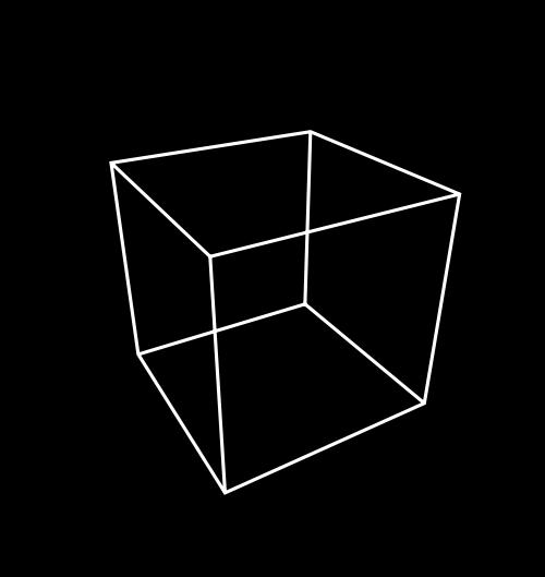
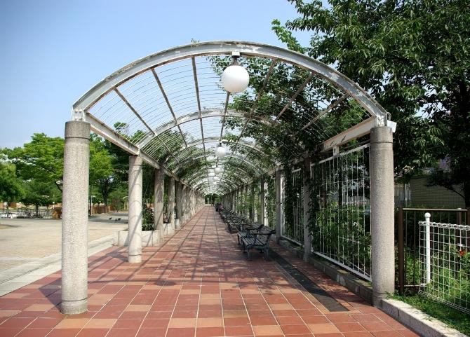
6 Perspective projection Perspective projection is a type of projection where three dimensional objects are not projected along parallel lines, but along lines emerging from a single point. This means that distant objects appear smaller than nearer objects; lines which are parallel in nature appear to intersect in the projected image. For example if railways are pictured with perspective projection, they appear to converge towards a single point, called vanishing point. Photographic lenses and the human eye work in the same way, therefore perspective projection looks most realistic.perspective projection is usually categorized into one-point, two-point and three-point perspective, depending on the orientation of the projection plane towards the axes of the depicted object.
7 Perspective projection
8 Perspective projection
9 Perspective projection
10 Perspective projection

11 Perspective projection

12 Perspective projection
13 Parallel projection In the Western world, we are accustomed to the linear perspective but another perspective had developed in oriental art. The Chinese perspective was an intrinsic part of the classical scroll painting. A typical Chinese scroll painting had a size of approximately 40 centimetres high by several meters wide. One views the painting by unrolling it on a table in segments of about 60 centimetres wide. We can say, that the Chinese scroll paintings show a development in time a form of narrative art, in contrast to the paintings that were made in Europe at the time, which show a situation rather than a development.
14 Parallel projection Along the River During Qingming Festival
15 Parallel projection Problems with parallel projection Objects drawn with parallel projection do not appear larger or smaller as they extend closer to or away from the viewer. While advantageous for technical drawings, where measurements must be taken directly from the image, the result is a perceived distortion, since unlike perspective projection, this is not how our eyes or photography normally work. It also can easily result in situations where depth and altitude are dicult to gauge.


16 Parallel projection Problems with parallel projection

17 Parallel projection Problems with parallel projection
18 Parallel projection Axonometric projection One of the most important type of parallel projection is an axonometric projection. Axonometric projection is a type of parallel projection used to create a pictorial drawing of an object, where the object is rotated along one or more of its axes relative to the plane of projection. Parallel projections have lines of projection that are parallel both in reality and in the projection plane. Axonometric projection is a type of parallel projection where the object is rotated along one or more of its axes relative to the plane of projection. Axonometric projection is a type of parallel projection where the plane or axis of the object depicted is not parallel to the projection plane, such that multiple sides of an object are visible in the same image.
19 Parallel projection Axonometric projection There are three main types of axonometric projection which is a type of parallel projection: isometric, dimetric, and trimetric projection, depending on the exact angle at which the view deviates from the orthogonal.
20 Parallel projection Axonometric projection isometric projection Denition Isometric projection: This type of projection is widely used in technical and engineering drawings. The three coordinate axes are equally foreshortened and the angle between them is 120 degree. This makes it possible for the observer to have a sense of the object's real proportions.
21 Parallel projection Axonometric projection dimetric projection Denition Dimetric projection: In this projection only two of the axes are equally foreshortened. The scale of the third direction is determined separately. This projection is most often used in videogames and pixel art.
22 Parallel projection Axonometric projection trimetric projection Denition Trimetric projection: Here the direction of observing is such that all of the axes appear unequally foreshortened.

23 Parallel projection Axonometric projection
24 Parallel projection Axonometric projection important property A more important property of axonometry is its xed relation between sizes of objects in world space and those on projected space, independent of the positions of the objects in projected space. In linear perspective, objects become smaller when they move farther away; not so in axonometric perspective. This means that we can measure the size of an object of a axonometric drawing and know how big the real object is (we need to know the scale of the drawing and the properties of the projection, but nothing else), something that cannot be done with linear perspective. This leads to the name of the projection: the word axonometry means measurable from the axes.
25 Parallel projection Axonometric projection important property The main properties of axonometric projections are: No vanishing points. This allows to scroll a large image below a viewport and to have the same perspective at any point. Lines that are parallel in the 3-dimensional space remain parallel in the 2-dimensional picture. This is in contrast with the linear perspective, where parallel lines along the z-axis in the 3-dimensional space collapse to a single vanishing point at the horizon in the 2-dimensional picture. Objects that are distant have the same size as objects that are close; objects do not get smaller as they move away from the viewer. If we know the scale of the axes, we can measure the size (width, height, length, depth) of an object directly from the picture, regardless of its position on the z-axis; hence the name axonometry. The axonometric projections are standardized for technical drawings. These standards are optimized for ease of use versus visual realism.
26 Parallel projection Axonometric projection practice In practice (in computer graphics) axonometry, is a drawing technique where the orthogonal x, y and z axes of the (3-dimensional) world space are projected to (non-orthogonal) axes on paper. In the projection, the y axis usually remains the vertical axis, the z axis is skewed and the x axis may either be horizontal, or be skewed as well. Although there are countless possible axonometric projections, only two are standardized for technical drawings which are discussed in the following.
27 Parallel projection Axonometric projection practice When we want to use axonomertic projection two problems rises: 1 What are common (or well-proportioned) axonometric projections, and how persvasive does each look? 2 At what angles does one look at board in an axonometric projection? It is tempting to use rendered 3-D objects on an axonometric map, as sprites. To specify the position and orientation of the camera (view point) in relation to the object, we will need to know the intrinsic angles of the axonometric map that we are using.
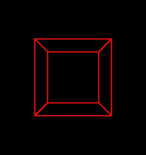
28 Parallel projection Axonometric projection practice: the isometric projection As we know from the previous part, the isometric projection is a type of axonometric projection which is in turn a type of parallel projection. The term isometric comes from the Greek for equal measure (gr. isos equal), reecting that the scale along each axis of the projection is the same (unlike some other forms of graphical projection). It means that in an isometric projection, the x, y and z axes have the same metric: a unit along the x axis is equally long along the y and z axes. In other words, if we render a wire frame cube, all edges in the 2-dimensional picture are equally long. Another property of the isometric projection is that the projected wire frame cube is also symmetric. All sides of the projected cube are rhombuses.
29 Isometric projection as a standard The international standard ISO (Technical drawings Projection methods Part 3: Axonometric representations; PN-EN ISO :2002 Rysunek techniczny Metody rzutowania Cz ± 3: Przedstawianie aksonometryczne) describes an isometric projection that is symmetric with regards to the vertical axis; the angle between the x and y axes, and between the z and y axes, is 60 degrees. The projection shows three sides of a cube, and the surfaces of each side are equal. The 30 angle between the x and z axes and the horizon is convenient for technical drawings, because the sine of 30 is 1 2.
30 Isometric projection in computer games Computer games with isometric maps are often tile-based. To make tiles match, the game designer must take into account how diagonal lines are plotted in discrete steps. As it turns out, a line at 30 degrees (sine is 0.5) produces steps that are too irregular. A line at an angle where the tangent is 0.5 does have a nice regular pattern: two steps to the right, one step up. Thus, the isometric projection used by most games tilt the x and z axes with approximately 27 degrees (the exact angle is arc tg(0.5)). Because the tangent of the angle of the rhombus is 0.5, the rhombus is twice as wide as it is high. This is why many sources mention a 1:2 scale for isometric perspectives.
31 Isometric projection in military The two isometric projections mentioned above skew all faces of the example cube. In applications where the most important faces are the horizontal ones, for example in applications where maps or oor plans are paramount, another isometric projection is common. It is called the military projection, probably because of its origin or use. In the military projection, the angles of the x and z axes are at 45, meaning that the angle between the x axis and the z axis is 90. That is, the x z plane is not skewed. It is rotated over 45, though.
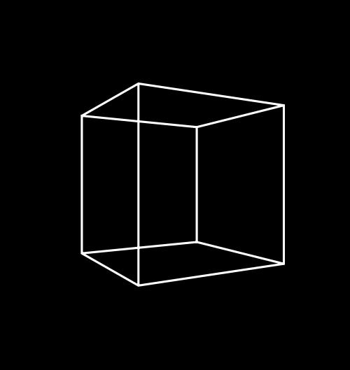
32 The dimetric projection In the dimetric projection, one of the three axes has a dierent scale than the other two. In practice, the scaled axis is the z axis and, hence, a cube drawn in a dimetric projection is not a symmetrical graphic (like in the isometric projection).
33 Dimetric projection in computer games As was the case with the isometric projection, in computer graphics some angles are preferable to others. The rst dimetric projection we can use for (tiled) computer graphics is very similar to the projection of Chinese scroll paintings. The dierence is the scale of the z-axis, and the angle that it makes with the x axis. To start with the angle, the z-axis is slanted with approximately 27 degrees (the exact angle is arc tg(0.5)). This is the same angle as the isometric projection for computer graphics uses. The scale is such that the width of the side view of a cube, when measured along the x axis, is half of the width of the front face. The key phrase in the previous sentence is when measured along the x axis. In the two former projections, the scale factor applied to distances measured along the z axis.
34 Dimetric projection in platform games The above projection gives a perspective that is viewed mostly from the side. I might be useful to add some depth to a side-scrolling (or platform) game. For board-like games, a perspective that is viewed from a greater height is more appropriate. The second proposed dimetric projection for games serves this end. Again, note that the perspective of the two projections suggested above is distorted. The angles in the top and side views are really approximate. For example, in the second projection the angle at which one looks from above at the scene is given as 24 degrees. However, using an angle of 30 degrees may actually look better. In addition, a 30-degree angle lets us use the same objects for both the dimetric and the isometric projections for games.
35 Conversion from 3D to 2D: Isometric Converting from space coordinates (x, y, z) to a pixel coordinate (x, y ) in the projection requires only trivial geometry (we consider left-handed orientation). x = (x z) cos(30) y = y + (x + z) sin(30)
36 Conversion from 3D to 2D: Isometric (computer games) x = (x z) y = y + x+z 2
37 Conversion from 3D to 2D: Dimetric (ISO) x = x cos(7) + cos(42) z 2 y = y + sin(42) z 2 x sin(7)
38 Conversion from 3D to 2D: Dimetric (computer games: side view) x = x + z 2 y = y + z 4
39 Conversion from 3D to 2D: Dimetric (computer games: top view) x = x + z 4 y = y + z 2
40 Isometric and hexagonal maps Tile Maps A tile-based game is a game that uses tiles as one of the fundamental elements of play. Traditional tile-based games use small tiles as playing pieces for gambling or entertainment games.
41 Three types of tiles Square. A tile-based game often uses square ar rectangular sections of the screen to represent the individual tile. Typically, whatever occupies the tile is contained wholly within it and does not extend beyond the borders of the square are rectangle. This makes rendering portions of rectangular maps really easy, as you can redraw a portion of the map without worrying too much about the other portions. Rhombus. Unlike rectangular maps, the tiles in an isometric grid almost always have a graphic that exceeds the boundaries of the tile. This makes the rendering order of the tiles important. Hexagon. A tile-based game that uses a hexagonal map consists of hexagons. Like rectangular maps, the tiles in a hex grid usually entirely contain the objects within them, so rendering updates is pretty simple but still not as trivial as rectangular maps.

42 Isometric and hexagonal maps. How maps are constructed square case In a rectangular map, life is easy.
 case In this case we have a choice between staggered map and diamond map.")
43 Isometric and hexagonal maps. How maps are constructed rhombus (isometric) case In this case we have a choice between staggered map and diamond map. In a staggered map, rows are strung horizontally, and columns zigzag from the top of the map to the bottom of the map.
 case In a diamond")
44 Isometric and hexagonal maps. How maps are constructed rhombus (isometric) case In a diamond map, rows and columns go on a diagonal.

45 Isometric and hexagonal maps. How maps are constructed hexagon case In this case, like for rhombus case, we have a choice between staggered map and diamond map. In a staggered map, rows are strung horizontally, and columns zigzag from the top of the map to the bottom of the map.

46 Isometric and hexagonal maps. How maps are constructed hexagon case In a diamond map, rows and columns go on a diagonal.
47 Isometric and hexagonal maps. Ploting tales rectangular case One of the main things to deal with when rendering a tile-based game is taking a map location somewhere on the grid and determining where on screen to render it. For a rectangular map, this is quite simple [PlotX ] = [TileX ] [TileWidth] [PlotY ] = [TileY ] [TileHeight]
48 Isometric and hexagonal maps. Ploting tales rectangular case image
49 Isometric and hexagonal maps. Ploting tales diamond case In a diamond map the x values of tiles increase downward and to the right, whereas the y values increase downward and to the left. [PlotX ] = ([TileX ] [TileY ]) ([TileWidth]/2) [PlotY ] = ([TileX ] + [TileY ]) ([TileHeight]/2)
50 Isometric and hexagonal maps. Ploting tales diamond case image
51 Isometric and hexagonal maps. Ploting tales staggered maps (rhombusa and hex) In a staggered maps (rhombusa and hex), we have that every other row is oset half a tile to the right. Also, there is a 50% overlap between rows, so only one half of the vertical distance needs to be travelled from one row to the next. [PlotX ] = [TileX ] [TileWidth] + ([TileY ]%2) ([TileWidth]/2) [PlotY ] = [TileY ] ([TileHeight]/2)
52 Isometric and hexagonal maps. Ploting tales staggered maps (rhombusa and hex) image
53 Isometric and hexagonal maps. Walking tales rectangular map Another important task in any tile-based game is moving from one tile location to another. In short, we must add some numbers to present x and y to move in a selected direction. For rectangular map it is very simple. Direction X dierence Y dierence North 0-1 Northeast 1-1 East 1 0 Southeast 1 1 South 0 1 Southwest -1 1 West -1 0 Northwest -1-1
54 Isometric and hexagonal maps. Walking tales rectangular map: example
55 Isometric and hexagonal maps. Walking tales diamond map Direction X dierence Y dierence North -1-1 Northeast 0-1 East 1-1 Southeast 1 0 South 1 1 Southwest 0 1 West -1 1 Northwest -1 0
56 Isometric and hexagonal maps. Walking tales diamond map: example
57 Isometric and hexagonal maps. Walking tales staggered map Direction X dierence Y dierence North 0-2 Northeast Y %2-1 East 1 0 Southeast Y %2 1 South 0 2 Southwest Y %2-1 1 West -1 0 Northwest Y %2-1 -1
58 Isometric and hexagonal maps. Walking tales staggered map: example
59 Isometric and hexagonal maps. Mouse mapping tales rectangular case [TileX ] = ([MouseX ] [Tile(0, 0)ScreenX ])/[TileWidth] [TileY ] = ([MouseY ] [Tile(0, 0)ScreenY ])/[TileHeight]
60 Isometric and hexagonal maps. Mouse mapping tales rectangular case
61 Isometric and hexagonal maps. Mouse mapping tales staggered and diamond case; step 1 First, we calculate rought approximation so we want to nd how many steps to the east and south we need to go (starting from (0, 0) tile). [RoughX ] = ([MouseX ] [Tile(0, 0)ScreenX ])/[TileWidth] [RoughY ] = ([MouseY ] [Tile(0, 0)ScreenY ])/[TileHeight]
62 Isometric and hexagonal maps. Mouse mapping tales staggered and diamond case; step 1
63 Isometric and hexagonal maps. Mouse mapping tales staggered and diamond case; step 2 Next we need to know where within the (RoughX, RoughY ) area the pointing device is. [FineX ] = ([MouseX ] [Tile(O, O)ScreenX ])%[TileWidth] [FineY ] = ([MouseY ] [Tile(O, O)ScreenY ])%[TileHeight]
64 Isometric and hexagonal maps. Mouse mapping tales staggered and diamond case; step 2
65 Isometric and hexagonal maps. Mouse mapping tales staggered and diamond case; step 3 Finally we have to check the FineX and FineY coordinates into the neighborhood map. We take the FineX and FineY coordinates and use a lookup table that maps tile location to a tile in that tile neighborhood. The lookup table will be based on a map of the tiles in the area.

66 Isometric and hexagonal maps. Mouse mapping tales staggered and diamond case; step 3

67 Isometric and hexagonal maps. Mouse mapping tales staggered and diamond case; step 3
68 Isometric and hexagonal maps. Mouse mapping tales staggered and diamond case; step 3 If the coordinate is in region A, take one step to the northwest. If in B, to the northeast. If in C, no change. If in D, one step to the southwest, and if in E, one step to the southeast.
69 Isometric and hexagonal maps. Mouse mapping tales staggered and diamond case; step 3
I B.TECH- I SEMESTER DEPARTMENT OF MECHANICAL ENGINEERING ENGINEERING DRAWING
 I B.TECH- I SEMESTER DEPARTMENT OF MECHANICAL ENGINEERING ENGINEERING DRAWING ENGINEERING DRAWING UNIT-V DEFINITIONS: Axonometric Trimetric Dimetric Isometric It is a parallel technique used to create
Exploring 3D in Flash
 1 Exploring 3D in Flash We live in a three-dimensional world. Objects and spaces have width, height, and depth. Various specialized immersive technologies such as special helmets, gloves, and 3D monitors
technical drawing
 technical drawing school of art, design and architecture nust spring 2011 http://www.youtube.com/watch?v=q6mk9hpxwvo http://www.youtube.com/watch?v=bnu2gb7w4qs Objective abstraction - axonometric view
Transform 3D objects on to a 2D plane using projections
 PROJECTIONS 1 Transform 3D objects on to a 2D plane using projections 2 types of projections Perspective Parallel In parallel projection, coordinate positions are transformed to the view plane along parallel
ENGINEERING GRAPHICS 1E9
 Lecture 3 Monday, 15 December 2014 1 ENGINEERING GRAPHICS 1E9 Lecture 3: Isometric Projections Lecture 3 Monday, 15 December 2014 2 What is ISOMETRIC? It is a method of producing pictorial view of an object
Bridge Course On Engineering Drawing for Mechanical Engineers
 G. PULLAIAH COLLEGE OF ENGINEERING AND TECHNOLOGY Accredited by NAAC with A Grade of UGC, Approved by AICTE, New Delhi Permanently Affiliated to JNTUA, Ananthapuramu (Recognized by UGC under 2(f) and 12(B)
Isometric Projection Drawing CHAPTER 6
 Isometric Projection Drawing CHAPTER 6 Content Overview Pictorial projection Parallel projection Axonometric projection Isometric projection Axes and selection Isometric lines and planes Isometric scale
Student Name: Teacher: Date: District: Rowan. Assessment: 9_12 T and I IC61 - Drafting I Test 1. Description: Unit C - Sketching - Test 2.
 Student Name: Teacher: Date: District: Rowan Assessment: 9_12 T and I IC61 - Drafting I Test 1 Description: Unit C - Sketching - Test 2 Form: 501 1. The most often used combination of views includes the:
Chapter 5 Pictorial sketching
 Chapter 5 Pictorial sketching Contents Freehand sketching techniques Pictorial projections - Axonometric - Oblique Isometric projection vs isometric sketch Isometric sketch from an orthographic views Isometric
Projections. Conceptual Model of the 3D viewing process
 Projections Projections Conceptual Model of the 3D viewing process 3D Projections (Rays converge on eye position) (Rays parallel to view plane) Perspective Parallel Orthographic Oblique Elevations Axonometric
Interactive Computer Graphics A TOP-DOWN APPROACH WITH SHADER-BASED OPENGL
 International Edition Interactive Computer Graphics A TOP-DOWN APPROACH WITH SHADER-BASED OPENGL Sixth Edition Edward Angel Dave Shreiner 228 Chapter 4 Viewing Front elevation Elevation oblique Plan oblique
Perspective in 2D Games
 Lecture 16 in 2D Games Drawing Images Graphics Lectures SpriteBatch interface Coordinates and Transforms bare minimum to draw graphics Drawing Camera Projections side-scroller vs. top down Drawing Primitives
3D Viewing I. Acknowledgement: Some slides are from the Dr. Andries van Dam lecture. CMSC 435/634 August D Viewing I # /27
 3D Viewing I Acknowledgement: Some slides are from the Dr. Andries van Dam lecture. From 3D to 2D: Orthographic and Perspective Projection Part 1 Geometrical Constructions Types of Projection Projection
Perspective in 2D Games
 Lecture 16 in 2D Games Take Away for Today What is game camera? How does it relate to screen space? Object space? How does camera work in a 2D game? 3D? How do we give 2D games depth? Advantages, disadvantages
UNIT 5a STANDARD ORTHOGRAPHIC VIEW DRAWINGS
 UNIT 5a STANDARD ORTHOGRAPHIC VIEW DRAWINGS 5.1 Introduction Orthographic views are 2D images of a 3D object obtained by viewing it from different orthogonal directions. Six principal views are possible
11/12/2015 CHAPTER 7. Axonometric Drawings (cont.) Axonometric Drawings (cont.) Isometric Projections (cont.) 1) Axonometric Drawings
 Axonometric Drawings (cont.) Isometric Projections (cont.) 1) Axonometric Drawings") CHAPTER 7 1) Axonometric Drawings 1) Introduction Isometric & Oblique Projection Axonometric projection is a parallel projection technique used to create a pictorial drawing of an object by rotating the
CHAPTER 7 1) Axonometric Drawings 1) Introduction Isometric & Oblique Projection Axonometric projection is a parallel projection technique used to create a pictorial drawing of an object by rotating the
Perspective in 2D Games
 Lecture 15 in 2D Games Drawing Images Graphics Lectures SpriteBatch interface Coordinates and Transforms bare minimum to draw graphics Drawing Camera Projections side-scroller vs. top down Drawing Primitives
Introduction to Projection The art of representing a three-dimensional object or scene in a 2D space is called projection.
 Introduction to Projection The art of representing a three-dimensional object or scene in a 2D space is called projection. Projection is carried out by passing projectors through each vertex and intersecting
Extension material for Level 2 Design and Visual Communication Study Guide
 3-D formal drawing Extension material for Level 2 Design and Visual Communication Study Guide ISBN 978-1-927194-15-7 For individual student use only. No other use permitted. ESA Publications (NZ) Ltd,
Classical Viewing. Ed Angel Professor of Computer Science, Electrical and Computer Engineering, and Media Arts University of New Mexico
 Classical Viewing Ed Angel Professor of Computer Science, Electrical and Computer Engineering, and Media Arts University of New Mexico 1 Objectives Introduce the classical views Compare and contrast image
Isometric Drawing Chapter 26
 Isometric Drawing Chapter 26 Sacramento City College EDT 310 EDT 310 - Chapter 26 - Isometric Drawing 1 Drawing Types Pictorial Drawing types: Perspective Orthographic Isometric Oblique Pictorial - like
Perspective. Announcement: CS4450/5450. CS 4620 Lecture 3. Will be MW 8:40 9:55 How many can make the new time?
 Perspective CS 4620 Lecture 3 1 2 Announcement: CS4450/5450 Will be MW 8:40 9:55 How many can make the new time? 3 4 History of projection Ancient times: Greeks wrote about laws of perspective Renaissance:
In addition to one-point perespective, another common perspective
 CHAPTR 5 Two-Point Perspective In addition to one-point perespective, another common perspective drawing technique is two-point perspective, illustrated in Figure 5.1. Unless otherwise stated, we will
Introduction to Computer Graphics (CS602) Lecture 19 Projections
 Lecture 19 Projections") Introduction to Computer Graphics (CS602) Lecture 19 Projections For centuries, artists, engineers, designers, drafters, and architects have been facing difficulties and constraints imposed by the problem
Introduction to Computer Graphics (CS602) Lecture 19 Projections For centuries, artists, engineers, designers, drafters, and architects have been facing difficulties and constraints imposed by the problem
ONE-POINT PERSPECTIVE
 NAME: PERIOD: PERSPECTIVE Linear Perspective Linear Perspective is a technique for representing 3-dimensional space on a 2- dimensional (paper) surface. This method was invented during the Renaissance
1. When sketching long, narrow objects in OBLIQUE, distortion can be lessened by placing the long dimension along:
 Draft Student Name: Teacher: District: Date: Wake County Test: 9_12 T and I IC61 - Drafting I Test 2 Description: 3.03 Apply 3D sketching Form: 501 1. When sketching long, narrow objects in OBLIQUE, distortion
History of projection. Perspective. History of projection. Plane projection in drawing
 History of projection Ancient times: Greeks wrote about laws of perspective Renaissance: perspective is adopted by artists Perspective CS 4620 Lecture 3 Duccio c. 1308 1 2 History of projection Plane projection
ENGINEERING GRAPHICS UNIT V ISOMETRIC PROJECTION PERSPECTIVE PROJECTION
 ENGINEERING GRAPHICS UNIT V ISOMETRIC PROJECTION PERSPECTIVE PROJECTION 1.PICTORIAL PROJECTIONS To visualize the shape of the whole object in its 3- D form, all the two or three orthographic views of the
ISOMETRIC PROJECTION. Contents. Isometric Scale. Construction of Isometric Scale. Methods to draw isometric projections/isometric views
 ISOMETRIC PROJECTION Contents Introduction Principle of Isometric Projection Isometric Scale Construction of Isometric Scale Isometric View (Isometric Drawings) Methods to draw isometric projections/isometric
Copyrighted Material. Copyrighted Material. Copyrighted. Copyrighted. Material
 Engineering Graphics ORTHOGRAPHIC PROJECTION People who work with drawings develop the ability to look at lines on paper or on a computer screen and "see" the shapes of the objects the lines represent.
Chapter 5 Pictorial Projection
 Chapter 5 Pictorial Projection Objectives After completing this chapter, the students will be able to Create freehand sketches using the correct sketching techniques. Explainthe difference between axonometric
3D Viewing I. From 3D to 2D: Orthographic and Perspective Projection Part 1
 From 3D to 2D: Orthographic and Perspective Projection Part 1 3D Viewing I By Andries van Dam Geometrical Constructions Types of Projection Projection in Computer Graphics Jian Chen January 15, 2010 3D
Drawing: technical drawing TECHNOLOGY
 Drawing: technical drawing Introduction Humans have always used images to communicate. Cave paintings, some of which are over 40,000 years old, are the earliest example of this artistic form of communication.
VIEWING 1. CLASSICAL AND COMPUTER VIEWING. Computer Graphics
 VIEWING We now investigate the multitude of ways in which we can describe our virtual camera. Along the way, we examine related topics, such as the relationship between classical viewing techniques and
3D Viewing. Introduction to Computer Graphics Torsten Möller / Manfred Klaffenböck. Machiraju/Zhang/Möller
 3D Viewing Introduction to Computer Graphics Torsten Möller / Manfred Klaffenböck Machiraju/Zhang/Möller Reading Chapter 5 of Angel Chapter 13 of Hughes, van Dam, Chapter 7 of Shirley+Marschner Machiraju/Zhang/Möller
Indian Institute of Technology Kanpur National Programme on Technology Enhanced Learning (NPTEL) Course Title Engineering Graphics
 Course Title Engineering Graphics") Indian Institute of Technology Kanpur National Programme on Technology Enhanced Learning (NPTEL) Course Title Engineering Graphics Lecture 10 Isometric Projections-Part-II by Prof. Nihar Ranjan Patra Department
Indian Institute of Technology Kanpur National Programme on Technology Enhanced Learning (NPTEL) Course Title Engineering Graphics Lecture 10 Isometric Projections-Part-II by Prof. Nihar Ranjan Patra Department
 Visual Arts TANGENCIES Two figures are tangents when they have only one point in common, called the point of tangency. Types of tangencies. There are tangencies between circumferences or between straight
Engineering & Computer Graphics Workbook Using SOLIDWORKS
 Engineering & Computer Graphics Workbook Using SOLIDWORKS 2017 Ronald E. Barr Thomas J. Krueger Davor Juricic SDC PUBLICATIONS Better Textbooks. Lower Prices. www.sdcpublications.com Powered by TCPDF (www.tcpdf.org)
6. Draw the isometric view of a cone 40 mm diameter and axis 55 mm long when its axis is horizontal. Draw isometric scale. [16]
![6. Draw the isometric view of a cone 40 mm diameter and axis 55 mm long when its axis is horizontal. Draw isometric scale. [16]](/thumbs/85/92603403.jpg "6. Draw the isometric view of a cone 40 mm diameter and axis 55 mm long when its axis is horizontal. Draw isometric scale. [16]") Code No: R05010107 Set No. 1 I B.Tech Supplimentary Examinations, Aug/Sep 2007 ENGINEERING GRAPHICS ( Common to Civil Engineering, Mechanical Engineering, Mechatronics, Metallurgy & Material Technology,
Code No: R05010107 Set No. 1 I B.Tech Supplimentary Examinations, Aug/Sep 2007 ENGINEERING GRAPHICS ( Common to Civil Engineering, Mechanical Engineering, Mechatronics, Metallurgy & Material Technology,
Evaluation Chapter by CADArtifex
 The premium provider of learning products and solutions www.cadartifex.com EVALUATION CHAPTER 2 Drawing Sketches with SOLIDWORKS In this chapter: Invoking the Part Modeling Environment Invoking the Sketching
Perspective Sketching
 Perspective Sketching Perspective Drawings A perspective drawing offers the most realistic three-dimensional view of all the pictorial methods, because it portrays the object in a manner that is most similar
CHAPTER 01 PRESENTATION OF TECHNICAL DRAWING. Prepared by: Sio Sreymean
 CHAPTER 01 PRESENTATION OF TECHNICAL DRAWING Prepared by: Sio Sreymean 2015-2016 Why do we need to study this subject? Effectiveness of Graphics Language 1. Try to write a description of this object. 2.
60 Most Important Engineering Drawing Questions
 1. If a client of yours is having difficulty visualizing a design, what type of drawing would be the easiest to understand? A. axonometric B. three-view orthographic C. one-view orthographic D. bimetric
1 st Subject: Types of Pictorial Drawings (Isometric, Oblique, and Perspective)
") Intermediate Engineering Graphics 4 th Week 1 st Meeting Lecture Notes Instructor: Edward N. Locke Topic: Types of pictorial drawings (isometric, oblique, and perspective), isometric sketching and drafting
Intermediate Engineering Graphics 4 th Week 1 st Meeting Lecture Notes Instructor: Edward N. Locke Topic: Types of pictorial drawings (isometric, oblique, and perspective), isometric sketching and drafting
Peter Clements Art Studios
 Peter Clements Art Studios How to Erase Pencil Axonometric Projection or drawing is referred to as a projection as they do not have vanishing points as the conventional perspective drawing. Consequently,
matics A presentation by Fernando Corbalán
 y matics A presentation by Fernando Corbalán JORNADAS SOBRE EL APRENDIZAJE Y LA ENSEÑANZA DE LAS MATEMÁTICAS Centro de Arte y Creación Industrial 1. 3. 4. 5. In Search for Beauty: The Common Territory
technical drawing school of art, design and architecture sarah adeel nust spring 2011
 technical drawing school of art, design and architecture sarah adeel nust spring 2011 the ability to document imagination. a mean to design reasoning spring 2011 perspective drawings technical drawing
NAME: PERIOD: Perspective Packet (Week One)
") NAME: PERIOD: Perspective Packet (Week One) The following are your beginning assignments for perspective. You are to complete ONE page at a time. When you finish each page show it to me to sign off and
NAME: PERIOD: Perspective Packet (Week One) The following are your beginning assignments for perspective. You are to complete ONE page at a time. When you finish each page show it to me to sign off and
8.2 IMAGE PROCESSING VERSUS IMAGE ANALYSIS Image processing: The collection of routines and
 8.1 INTRODUCTION In this chapter, we will study and discuss some fundamental techniques for image processing and image analysis, with a few examples of routines developed for certain purposes. 8.2 IMAGE
EDUCATIONAL REND LAKE COLLEGE CAD INTRODUCTION TO COMPUTER-AIDED DRAFTING ISOMETRIC DRAWING REVISED: FALL 2010 INSTRUCTOR: THOMAS ARPASI
 INSTRUCTOR: THOMAS ARPASI REND LAKE COLLEGE CAD 1201-51 INTRODUCTION TO COMPUTER-AIDED DRAFTING ISOMETRIC DRAWING 1 Pictoral Drawing Pictoral drawing have evolved from cave paintings to photorealistic
Perspective in Art. Yuchen Wu 07/20/17. Mathematics in the universe. Professor Hubert Bray. Duke University
 Perspective in Art Yuchen Wu 07/20/17 Mathematics in the universe Professor Hubert Bray Duke University Introduction: Although it is believed that science is almost everywhere in our daily lives, few people
Dr. Reham Karam. Perspective Drawing. For Artists & Designers. By : Dr.Reham Karam
 Perspective Drawing For Artists & Designers By : Dr.Reham Karam Geometry and Art : What is perspective? Perspective, in the vision and visual perception, is : the way that objects appear to the eye based
The Grade 6 Common Core State Standards for Geometry specify that students should
 The focus for students in geometry at this level is reasoning about area, surface area, and volume. Students also learn to work with visual tools for representing shapes, such as graphs in the coordinate
(Ans:d) a. A0 b. A1 c. A2 d. A3. (Ans:b) (Ans:a) (Ans:d) (Ans:d)
 a. A0 b. A1 c. A2 d. A3. (Ans:b) (Ans:a) (Ans:d) (Ans:d)") Multiple Choice Questions (MCQ) on Engineering Drawing (Instruments) The mini drafter serves the purpose of everything except a. Scales b. Set square c. Protractor d. Compass (Ans:d) During operation,
Multiple Choice Questions (MCQ) on Engineering Drawing (Instruments) The mini drafter serves the purpose of everything except a. Scales b. Set square c. Protractor d. Compass (Ans:d) During operation,
Engineering Working Drawings Basics
 Engineering Working Drawings Basics Engineering graphics is an effective way of communicating technical ideas and it is an essential tool in engineering design where most of the design process is graphically
CE 100 Civil Engineering Drawing Sessional (Lab Manual)
") CE 100 Civil Engineering Drawing Sessional (Lab Manual) Department of Civil Engineering Ahsanullah University of Science and Technology November, 2017 1 Preface This course is designed to provide civil
CE 100 Civil Engineering Drawing Sessional (Lab Manual) Department of Civil Engineering Ahsanullah University of Science and Technology November, 2017 1 Preface This course is designed to provide civil
COPYRIGHTED MATERIAL. Overview
 In normal experience, our eyes are constantly in motion, roving over and around objects and through ever-changing environments. Through this constant scanning, we build up experience data, which is manipulated
Multi-View Drawing Review
 Multi-View Drawing Review Sacramento City College EDT 300/ENGR 306 EDT 300 / ENGR 306 - Chapter 5 1 Objectives Identify and select the various views of an object. Determine the number of views needed to
COPYRIGHTED MATERIAL OVERVIEW 1
 OVERVIEW 1 In normal experience, our eyes are constantly in motion, roving over and around objects and through ever-changing environments. Through this constant scanning, we build up experiential data,
Technological Design Mr. Wadowski. Orthographic & Isometric Drawing Lesson
 Technological Design Mr. Wadowski Orthographic & Isometric Drawing Lesson TOPICS Working Drawings, Isometric Drawings & Orthographic Drawings Glass box concept Multiview projection Orthographic projection
Projections Computer Graphics and Visualization
 Planar Geometric Fall 2010 Standard projections project onto a plane Projectors are lines that either converge at a center of projection are parallel Nonplanar projections are needed for applications such
JUNIOR CERTIFICATE 2009 MARKING SCHEME TECHNICAL GRAPHICS HIGHER LEVEL
 . JUNIOR CERTIFICATE 2009 MARKING SCHEME TECHNICAL GRAPHICS HIGHER LEVEL Sections A and B Section A any ten questions from this section Q1 12 Four diagrams, 3 marks for each correct label. Q2 12 2 marks
Engineering Graphics with SOLIDWORKS 2016 and Video Instruction
 Engineering Graphics with SOLIDWORKS 2016 and Video Instruction A Step-by-Step Project Based Approach David C. Planchard, CSWP, SOLIDWORKS Accredited Educator SDC PUBLICATIONS Better Textbooks. Lower Prices.
CS354 Computer Graphics Viewing and Projections
 Slide Credit: Donald S. Fussell CS354 Computer Graphics Viewing and Projections Qixing Huang February 19th 2018 Eye Coordinates (not NDC) Planar Geometric Projections Standard projections project onto
ONE POINT PERSPECTIVE
 ONE POINT PERSPECTIVE O che dolce cosa è questa prospettiva! (Oh that sweet thing is this perspective!) -Paolo Uccello Linear Perspective Line-based drawing method Objects seem to get smaller as they recede.
Describing an Angle Bracket
 Basics of Drafting Describing an Angle Bracket Orthographic Projection Orthographic drawings represent three dimensional objects in three separate views arranged in a standard manner. Orthographic Views
CS475/CS675 Computer Graphics
 CS475/CS675 Computer Graphics Viewing Perspective Projection Projectors Centre of Projection Object Image Plane or Projection Plane 2 Parallel Projection Projectors Centre of Projection? Object Image Plane
Engineering & Computer Graphics Workbook Using SolidWorks 2014
 Engineering & Computer Graphics Workbook Using SolidWorks 2014 Ronald E. Barr Thomas J. Krueger Davor Juricic SDC PUBLICATIONS Better Textbooks. Lower Prices. www.sdcpublications.com Powered by TCPDF (www.tcpdf.org)
ENGINEERING DRAWING. 1. Set squares are used to draw different angles. What is the angel a formed by the 45⁰ set square? Give a brief answer.
 ENGINEERING DRAWING 1. Set squares are used to draw different angles. What is the angel a formed by the 45⁰ set square? Give a brief answer. 2. Which is the correct method of hatching a plane surface?
Chapter 8. Technical Drawings
 Chapter 8 Technical Drawing Technical Drawings Multiview drawings Also called three-view drawings Simple objects take three views Front, top, one side Title block Identifies who did the design Gives date,
Appendix. Springer International Publishing Switzerland 2016 A.Y. Brailov, Engineering Graphics, DOI /
 Appendix See Figs. A.1, A.2, A.3, A.4, A.5, A.6, A.7, A.8, A.9, A.10, A.11, A.12, A.13, A.14, A.15, A.16, A.17, A.18, A.19, A.20, A.21, A.22, A.23, A.24, A.25, A.26, A.27, A.28, A.29, A.30, A.31, A.32,
PASS Sample Size Software. These options specify the characteristics of the lines, labels, and tick marks along the X and Y axes.
 Chapter 940 Introduction This section describes the options that are available for the appearance of a scatter plot. A set of all these options can be stored as a template file which can be retrieved later.
Perspective. Cornell CS4620/5620 Fall 2012 Lecture Kavita Bala 1 (with previous instructors James/Marschner)
") CS4620/5620: Lecture 6 Perspective 1 Announcements HW 1 out Due in two weeks (Mon 9/17) Due right before class Turn it in online AND in class (preferably) 2 Transforming normal vectors Transforming surface
CS4620/5620: Lecture 6 Perspective 1 Announcements HW 1 out Due in two weeks (Mon 9/17) Due right before class Turn it in online AND in class (preferably) 2 Transforming normal vectors Transforming surface
Perspective. Basic Perspective For Drawing
 Perspective Basic Perspective For Drawing Perspective is one of the most important tools in drawing a 3-dimensional scene or object on a 2-dimensional surface. Types of Linear perspective: Single- (or
Engineering Drawing Lecture 5 PROJECTION THEORY
 University of Palestine College of Engineering & Urban Planning First Level Engineering Drawing Lecture 5 PROJECTION THEORY Lecturer: Eng. Eman Al.Swaity Eng.Heba hamad PART 1 PROJECTION METHOD TOPICS
1. What are the coordinates for the viewer s eye?
 Part I In this portion of the assignment, you are going to draw the same cube in different positions, using the Perspective Theorem. You will then use these pictures to make observations that should reinforce
Introduction to DSP ECE-S352 Fall Quarter 2000 Matlab Project 1
 Objective: Introduction to DSP ECE-S352 Fall Quarter 2000 Matlab Project 1 This Matlab Project is an extension of the basic correlation theory presented in the course. It shows a practical application
Perspective Notes 8 th Grade Art
 Perspective Notes 8 th Grade Art Perspective Perspective is the representation of three-dimensional objects on a flat twodimensional surface. In perspective drawing, objects are made to recede in space
A SPATIAL ILLUSION. Isometric Projection in the East
 A SPATIAL ILLUSION For centuries Oriental artists did not make wide use of linear perspective. Another spatial convention was satisfactory for their pictorial purposes. In Oriental art planes recede on
PASS Sample Size Software
 Chapter 945 Introduction This section describes the options that are available for the appearance of a histogram. A set of all these options can be stored as a template file which can be retrieved later.
2. Line composed of closely and evenly spaced short dashes in a drawing represents
 1. Hidden lines are drawn as (a) dashed narrow lines (b) dashed wide lines (c) long-dashed dotted wide line (d) long-dashed double dotted wide line Ans: (a) 2. Line composed of closely and evenly spaced
Geometry 2001 part 1
 Geometry 2001 part 1 1. Point is the center of a circle with a radius of 20 inches. square is drawn with two vertices on the circle and a side containing. What is the area of the square in square inches?
Beginning Engineering Graphics 3 rd Week Lecture Notes Instructor: Edward N. Locke Topic: The Coordinate System, Types of Drawings and Orthographic
 Beginning Engineering Graphics 3 rd Week Lecture Notes Instructor: Edward N. Locke Topic: The Coordinate System, Types of Drawings and Orthographic 1 st Subject: The Cartesian Coordinate System The Cartesian
3D COMPUTER GRAPHICS
 3D COMPUTER GRAPHICS http://www.tutorialspoint.com/computer_graphics/3d_computer_graphics.htm Copyright tutorialspoint.com In the 2D system, we use only two coordinates X and Y but in 3D, an extra coordinate
Chapter 2. Isometric Projection and Multi View Drawings. Below are the desired outcomes and usage competencies based on the completion of Chapter 2.
 Chapter 2 Below are the desired outcomes and usage competencies based on the completion of Chapter 2. Desired Outcomes: Understand Isometric Projection and 2D sketching. Knowledge of additional Projection
THREE-D CUBES A GUIDE TO THREE DIMENSIONAL DIAGRAMS NICK CONNOLLY. June 2004
 THREE-D CUBES A GUIDE TO THREE DIMENSIONAL DIAGRAMS NICK CONNOLLY June 2004 Copyright in this paper is owned by Educational Assessment Australia, NewSouthGlobal Pty Limited unless otherwise indicated.
MEASURING SHAPES M.K. HOME TUITION. Mathematics Revision Guides. Level: GCSE Foundation Tier
 Mathematics Revision Guides Measuring Shapes Page 1 of 17 M.K. HOME TUITION Mathematics Revision Guides Level: GCSE Foundation Tier MEASURING SHAPES Version: 2.2 Date: 16-11-2015 Mathematics Revision Guides
1 ISOMETRIC PROJECTION SECTION I: INTRODUCTION TO ISOMETRIC PROJECTION
 1 ISOMETRIC PROJECTION SECTION I: INTRODUCTION TO ISOMETRIC PROJECTION Orthographic projection shows drawings of an object in a two-dimensional format, with views given in plan, elevation and end elevation
Made Easy. Jason Pancoast Engineering Manager
 3D Sketching Made Easy Jason Pancoast Engineering Manager Today I have taught you to sketch in 3D. It s as easy as counting ONE, TWO, FIVE...er...THREE! When your sketch only lives in Y and in X, Adding
Form = a solid, three-dimensional area. It s boundaries are measured using height, width, and depth.
 Space Shape = a flat, two dimensional area. It s boundaries can be measured in height and width Form = a solid, three-dimensional area. It s boundaries are measured using height, width, and depth. Positive
Engineering Graphics with SolidWorks 2012
 INSIDE: Video Instruction DVD An audio/visual presentation of the tutorial projects Engineering Graphics with SolidWorks 2012 and Video Instruction DVD A Step-by-Step Project Based Approach Introductory
Perspective. CS 4620 Lecture Steve Marschner. Cornell CS4620 Spring 2018 Lecture 5
 Perspective CS 4620 Lecture 5 2018 Steve Marschner 1 Parallel projection To render an image of a 3D scene, we project it onto a plane Simplest kind of projection is parallel projection image projection
Copyrighted. Material. Copyrighted. Material. Copyrighted. Material. Copyrighted. Material
 ENGINEERING & COMPUTER GRAPHICS WORKBOOK Using SolidWorks 2008 Ronald E. Barr Thomas J. Krueger Theodore A. Aanstoos Davor Juricic SDC PUBLICATIONS Schroff Development Corporation www.schroff.com Better
2004 Academic Challenge
 2004 Academic Challenge ENGINEERING GRAPHICS TEST - REGIONAL Engineering Graphics Test Production Team Ryan Brown, Illinois State University Author/Team Coordinator Kevin Devine, Illinois State University
Dharmapuri LAB MANUAL. : B.E. - Civil Engineering Year & Semester : I Year / II Semester
 Dharmapuri 636 703 LAB MANUAL Regulation : 2013 Branch : B.E. - Civil Engineering Year & Semester : I Year / II Semester CE6261-COMPUTER AIDED DRAFTING AND MODELLING LABORATORY ICAL ENG VVIT DEPARTMENT
JUNIOR CERTIFICATE 2008 MARKING SCHEME TECHNICAL GRAPHICS HIGHER LEVEL
 JUNIOR CERTIFICATE 2008 MARKING SCHEME TECHNICAL GRAPHICS HIGHER LEVEL Sections A and B Section A - any ten questions from this Section Q1 12 Four diagrams, 3 marks for each correct label. Q2 12 3 height
2018 Technical Drawing Specifications Resource A guide to support VCE Visual Communication Design Study Design
 2018 Technical Drawing Specifications Resource A guide to support VCE Visual Communication Design Study Design 2018 22 VICTORIAN CURRICULUM AND ASSESSMENT AUTHORITY 1 Contents A guide to support VCE Visual
Drawing Daisy Wheel Angles and Triangles
 Drawing Daisy Wheel Angles and Triangles Laurie Smith Laurie Smith is an independent early-building design researcher, specialising in geometrical design systems. Because geometry was part of the medieval
Elements of Art: Space AVI1O
 Elements of Art: Space AVI1O Definition Space is an Element of Art referring to the emptiness or area between, around, above, below or within objects Perceiving Depth Your eyes and brain work together
Lesson 6: Introduction to One and Two Point Perspective
 Lesson 6: Introduction to One and Two Point Perspective By Darlene Nguyen - July 18, 2017 0 329 In this lesson, I m going to introduce one and two-point linear perspective. Perspective drawing is a way