PRODIM CT 3.2 & 3.3 MANUAL The Complete Solution
|
|
|
- Muriel Stokes
- 5 years ago
- Views:
Transcription


1 PRODIM CT 3.2 & 3.3 MANUAL The Complete Solution We measure it all!
2 General information Copyright All rights reserved. Apart from the legally laid down exceptions, no part of this publication may be reproduced, stored in an automated databank, or made public in any shape or form, be it electronically, mechanically, by photocopying, filming, or in any other manner, without prior written permission from Prodim International BV in Helmond (NL). Disclaimer The influence of the operator on the measuring process is dominant, thus making him fully responsible for accuracy and safety. While using the Proliner he must ensure that: No one is allowed near the cable or the control box while the pen is in use. A broken cable or dropped pen can cause rapid and unpredictable retraction of the cable which can severely injure anyone it might contact. We advise to make control measurements once in a while to ensure accuracy. The Proliner is a precision measuring machine. Let only trained personnel work with the Proliner. Do not use the Proliner in areas where there is a lot of construction work. Proliner is a registered brand name of Prodim International BV. Prodim CT 3.2 & 3.3 Version Copyright - Prodim International Page 3
 13 3 Measure 14 3.1 Proliner set-up 14 3.2 Check Settings 15 3.")
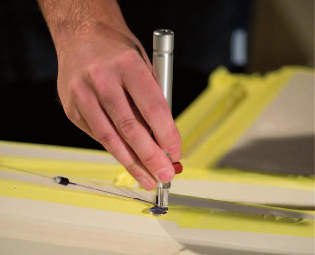
 Button 1 Push - registering a single point. The Proliner will automatically draw a straight line.")
3 Index 1 Getting started Remote control Proliner Main screen 5 2 Main Settings Introduction: essential concepts Pen Type Contour Compensation Projection Projection - Single Plaines Projection - Multiple Plaines Projection - 3D / None Make a plane (First Contour) 13 3 Measure Proliner set-up Check Settings Measuring Modes Starting up While measuring Saving and processing 17 4 Special function : Proliner-Leap 18 5 Checking Getting started 1.1 Proliner Remote ( ) Button 1 Push - registering a single point. The Proliner will automatically draw a straight line. This contour will consist of straight lines as well as radii, depending on the nature of the object to be measured. To end the line push the ( ) following the last point. ( ) Button 3 A. Push - Ends the contour and starts a new contour without moving to a new layer B. Push & Hold - Ends the contour and starts a new contour while moving to a new layer. You will hear a different and higher beep sound. ( ) Button 2 Push - registering multiple points until the button is pushed the second time. This contour will consist of straight lines as well as radii depending on the nature of the object to be measured. Push and release the button to start, push and release again to stop, do not hold it down. ( ) Button 4 A. Push - Delete the last point of the contour B. Push & Hold - delete the last contour, push & hold again and it will delete the previous contour. 6 Editing Overview / Modification functions Selection functions Measuring funtions Editing functions - part Editing functions - part Drawing functions - part Drawing functions - part Special functions 28 7 CT Module Overview CT Editing Sketches CT Report 37 8 Transfer 40 9 Tips 41 Line of Site (cord/wire cannot bend) It is important to plan where you set the Proliner so you can reach your points without bending the wire. To capture points around a corner, use the Leap Function. Take points on one side, make a leap to move the Proliner and then capture points on the next side. The process can be repeated until the object is completely captured in one measurement. 3 Point Plane (2D-3D) A 3 point plane is created by capturing three points on a surface. The triangle drawn between these points is the construction plane. Basic point to point measurement Touch with the pen the start point and Push ( ) Touch with the pen the second point and Push ( ). If you want to continue the contour, keep pressing the ( ) button. To end the contour press ( ) Continuous measurement Pushing the ( ) button starts continuous measurement. The Proliner will take points continuously until the ( ) button is pushed again. To separate continuous measurements push the ( ) button before starting the next continuous measurement It is helpful to measure at a moderate pace. The Proliner takes 10 points / sec. This means the faster you go the less points per meter you get. Prodim CT 3.2 & 3.3 Version Copyright - Prodim International Page 4 Prodim CT 3.2 & 3.3 Version Copyright - Prodim International Page 5


4 1. Getting started 1.2 Main Screen In the main screen, all the menus are accessible by pressing on the corresponding buttons. 2. Main Settings 2.1 Introduction: essential concepts There are 4 main concepts to know for correctly using the Proliner: 1- Pen type 2- Contour 3- Projection 4- Compensation It is very important to read and understand these basic concepts in order to make correct use of the Proliner. 2.2 Pen Type The operator has to specify which tool/pen is going to be used in the measurement. DEFAULT By default there are at least 2 pens installed on a Proliner. - Pointer: to be selected when only the spherical probe is used - Scanner: to be chosen when any add-on is attached to the spherical probe Battery indicator On the topside, you can see the battery indicator, which tells you how much power the battery has left. When 20% batterylevel is left, the Proliner starts beeping and shows that it is almost empty. Wrench By clicking the Wrench at the top, you will enter the General System Settings. Here you can for example select the Language and Units. You can change the beeping Volume and you can choose whether the screen should Flash or not when measuring a point. This can be useful when working in environments where it is difficult to hear the beep. Date and time Click on it to adjust the date and time. Proliner logo When pressing on the Proliner logo in the upper right corner, the screen will turn upside-down. This is useful when the Proliner is positioned on its backside. About Here you will find the serial number and software version of your Proliner and Prodim contact details. Shutdown Click on Shutdown to switch off the device. EXTRAS It is also possible to purchase more pens : - Toucher: pointed probe - Laser: you can connect the Prodim Laser to the Proliner - IPT: special measuring pen to measure hard-to-reach points, is included with the special Proliner IPT software module 2.3 Contour Open: the shape is left as measured (recommended for use on site) Closed: the program will automatically connect the last point measured with the first one (recommended for templates only) In the bottom left the name is shown to whom the device is Licensed. Disclaimer will lead to an extra window with the copyrights explained. The menu options: measure, open and transfer will be explained further in this manual. Prodim CT 3.2 & 3.3 Version Copyright - Prodim International Page 6 Prodim CT 3.2 & 3.3 Version Copyright - Prodim International Page 7


 direction. The object is on the right side of the measuring direction. The inside contour in CCW (Counter Clock Wise) direction.")

5 2. Main Settings 2.4 Compensation The Proliner always measures the center of the Pointer/ Scanner as Raw Point (or 3D). Pointer and Scanners therefore requires compensation. When projecting those points on a 2D plane it is possible to automatically compensate for the 2.5 mm radius of the tip. Then the user can choose between RIGHT or LEFT (and then measure in the correct direction) 2. Main Settings Example left compensation Wall Surface to be measured The Toucher/Laser/IPT do not require compensation. Be aware: Measuring in the wrong direction will result in measuring mistakes. Always check the compensation settings and make sure they are correct. Compensation: left! RIGHT Measuring an outside contour in CW (Clock Wise) direction. The object is on the right side of the measuring direction. The inside contour in CCW (Counter Clock Wise) direction. Only then the object is on the right side of the measuring direction. LEFT Measuring an outside contour in CCW direction. The object is on the left side of the measuring direction. The inside contour needs to be measured in CW direction. Only then the object is on the left side of the measuring direction. NONE The radius of the measuring pen is not corrected. The user can manually create a correction by drawing an offset in the CAD software. In 3D no compensation is possible. Prodim CT 3.2 & 3.3 Version Copyright - Prodim International Page 8 Prodim CT 3.2 & 3.3 Version Copyright - Prodim International Page 9

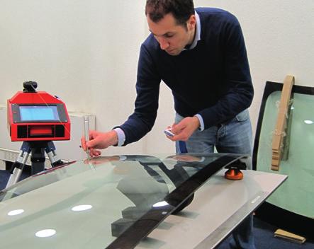
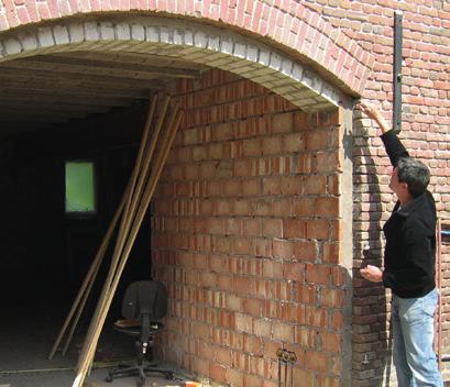
6 2. Main Settings 2. Main Settings 2.5 Projection The Proliner always measures in 3D. In order to create an output that is easier to process, 3D points can be projected on a 2D plane,. The operator can choose between 3 main approaches : 1- SINGLE PLANE A single plane for the whole file. All points measured will be projected on that level 2- MULTIPLE PLANES : Multiple planes are possible. Each plane is defined as a different layer. 3-3D (None) No projection. Points are kept in 3D 2.6 Projection - SINGLE PLANE Examples: Flat templates, Kitchen Tops, Windows, floors, single openings The Proliner measures 3D points which can be projected on a 2D plane. To define a 2D plane, you can choose a certain projection. The choice of projection will define how the plane is created AVARAGE E.g. A 2D template with one or more layers (where each layer is a hole or a different edge) The software will determine automatically the average of all measured points and will project all those points on that plane. This function is useful for when the measured points are already more or less on the same plane, for instance when a flat template is measured. The points will be automatically levelled, but this will cause only negligible mistakes FIRST CONTOUR E.g. Kitchen countertop and the sink in a separate drawing layer The average of the first contour of the first layer will define the position of the 2D plane for the whole file. The first measured contour acts as a projection plane. All remaining 3D points are projected on that level EXTRAS Only available with Proliner equipped with Inclinometers HORIZONTAL E.g. Top view of a room All points measured are projected to one horizontal 2D plane, the Proliner self-levels and creates a horizontal plane on the first contour level on the first point. VERTICAL E.g. One wall All points measured are projected to one vertical 2D plane, the Proliner self-levels and creates a vertical plane on the first contour level with at least two points. A plane in the Proliner can be: 1- AVARAGE Project on a automatically generated plane, without specifying it. 2- FIRST CONTOUR Projecting on a specific plane, specified by points measured and stored in the first contour, in the beginning of the measuring process. Note: Exceptions are always possible. Use the knowledge acquired during Proliner Training session to choose the best settings at any given time Prodim CT 3.2 & 3.3 Version Copyright - Prodim International Page 10 Prodim CT 3.2 & 3.3 Version Copyright - Prodim International Page 11


7 2. Main Settings 2. Main Settings 2.7 Projection - MULTIPLE PLANES 2.9 Make a Plane (First Contour) Examples: Kitchen Tops and Backsplash, rooms, yacht interiors, etc. 1 A plane is any flat, two dimensional surface. A minimum of three points must be taken to define a plane. Any 3 points create a plane. Once the points of the plane have been defined, all future points will be projected to that plane AVARAGE E.g. A 3D object where points can be measured on a section line The average of all points will define the position of the 2D plane. Every new layer will add points to the average plane. it is rarely used, if not for very specific situations FIRST CONTOUR E.g. A 3D space made of different surfaces, such as a room The average of the first contour of the first layer will define the position of the 2D plane. The first measured contour acts as a projection plane. Every new layer will use the first contour of the first layer as projection plane. Mostly used to measure rooms and such. 2 The edges of the plane are infinitely projected outwards using the information captured by your three point plane. This is the 2D surface that future points will be projected to EXTRAS Only available with Proliner equipped with Inclinometers HORIZONTAL (only with inclination sensor) E.g. Top view of a room All points measured are projected to one horizontal 2D plane, the Proliner self-levels and creates a horizontal plane on the first contour level on the first point. VERTICAL (only with inclination sensor) E.g. One wall All points measured are projected to one vertical 2D plane, the Proliner self-levels and creates a vertical plane on the first contour level with at least two points. 2.8 Projection - NONE/ 3D 3 Once you have established the projection plane with the 3 point contour, end the contour by pushing the ( ) button on the Proliner remote. The drawing is now ready to capture your 2D drawing in 3D space. It does not matter if you capture points above, below or on the plane, all the points will be projected perpendicular onto the plane. 4 The points are on a single plane allowing the data to be transferred for 2D production. Examples: Procutter, Plotter, CNC. Examples: 3D templates, glass windshields, 3D surfaces, 3D objects, canvas structures All points captured are in 3D space, it does NOT average or project points onto 2D planes. 3 4 Planes can be set at any angle IMPORTANT! When defining a plane: - do not measure points too close to each other - try to cover an area as big as possible - avoid to take points in a regular shape - take your time, it is important to do it properly - check on the screen if you are ready to proceed Note: Exceptions are always possible. Use the knowledge acquired during Proliner Training session to choose the best settings at any given time Prodim CT 3.2 & 3.3 Version Copyright - Prodim International Page 12 Prodim CT 3.2 & 3.3 Version Copyright - Prodim International Page 13
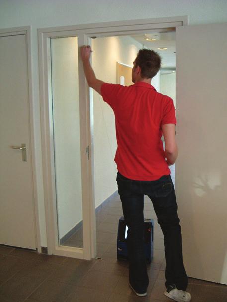
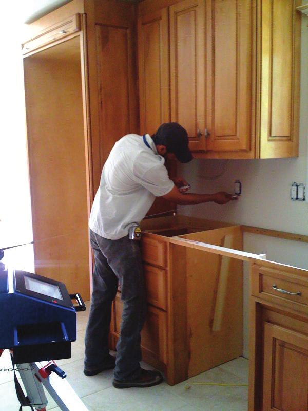
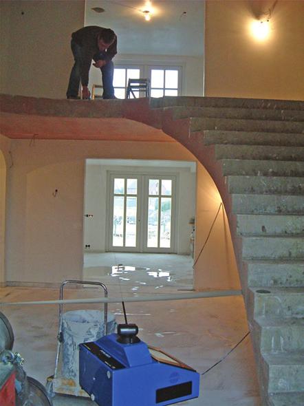
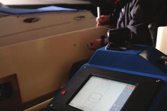
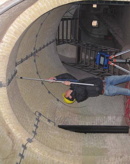
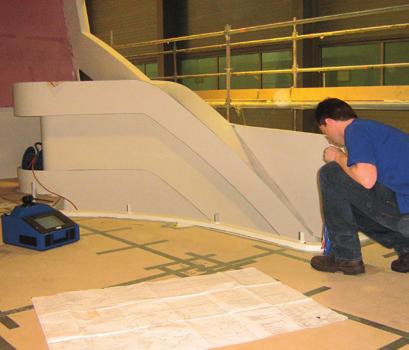
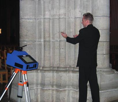
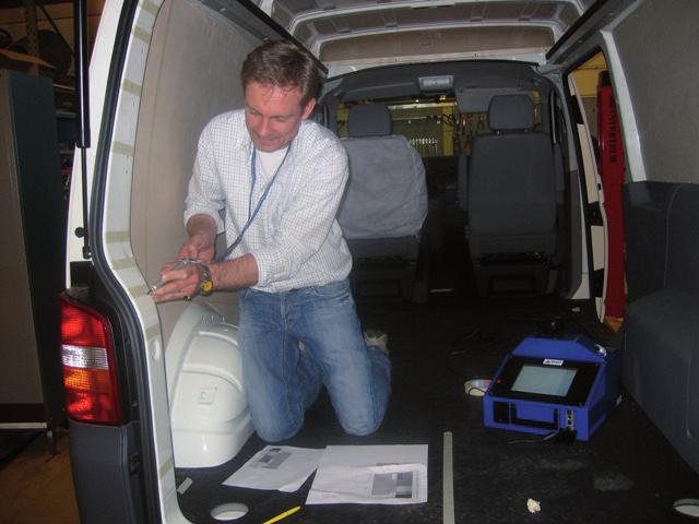
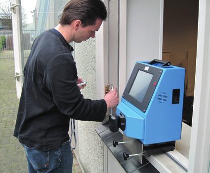
8 3. Measuring 3.1 Proliner set-up PROLINER Check Of course it is important to check if you have everything you need before starting a measurement, we advice you to alway bring: o The Proliner measuringe tool o Charged batteries o The Proliner remote o Proliner pen If needed bring the power cable and scanners. Position When measuring on-site, it is important to choose the ideal position for your Proliner. Choose a spot where you can: - maximize the reach of the machine - minimize problems with obstacles or blind spots it is convenient to have the screen of the Proliner facing the object if possible. Stability Make sure the Proliner is stable. Whether it is positioned on the floor, table or tripod. 3. Measuring 3.2 Check Settings Before starting to record points, it is important to: 1. Check the current settings at the bottom of the screen, make sure they are correct 2. If needed change the settings, by clicking on the Settings button on right sided menu (Refer to the theory described in the previous chapter) Measuring Modes Change Settings Level The Proliner does NOT need to be levelled. 3.3 Measuring Modes Check Settings OBJECT/AREA TO MEASURE Check Wise to check the object/area to measure before starting to identify potential problems or important details to be registered. Position it is better to have the object close to the Proliner, but not too close to interfere with the wire. Stability Make sure the object you want to measure is fixed/stable if it is a template, you could consider blocking it with a clamps or tape. STANDARD - DELIVERED WITH ALL PROLINER CS AND IS. Default solution to measure any project: templates, kitchentops, openings, balustrades, etc. OPTIONAL MEASURING MODES - AVAILABLE ONLY WHEN EXTRA MODULE ARE PURCHASED. Stairs Available in combination with the extra, optional module: STAIRSCHECK Refer to that module manual for more information Tube Available in combination with the extra, optional module: TUBECHECK Refer to that module manual for more information Door Available in combination with the extra, optional module: DOORCHECK Refer to that module manual for more information Prodim CT 3.2 & 3.3 Version Copyright - Prodim International Page 14 Prodim CT 3.2 & 3.3 Version Copyright - Prodim International Page 15


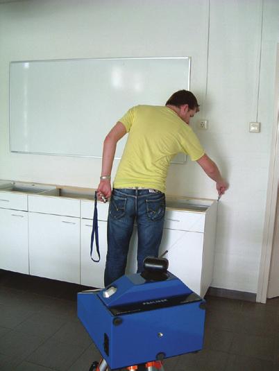
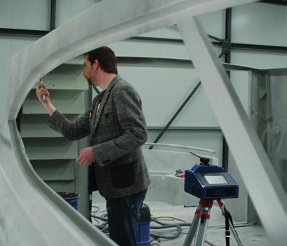
9 3. Measuring 3.4 Starting up Measuring 3.5 While measuring Measurements need to be performed properly. The quality of the final output depends greatly on the the working method of the the operator. Ideal measuring procedures are taught during Prodim Training sessions. In general, there are few aspect that are particularly important and that can be anticipated: o Do not move the Proliner before you are completely done and you are ready to save. o If you have to touch the Proliner or also its screen while measuring, be always very careful. o o o o o o The wire has to be able to pull with any interference (operator body, objects, Proliner case, etc) The arm has to be able to move freely up and down, left and right when you are recording a point Make sure the object is not moving. Take precautions if needed. Hold the pen firmly and safely. Pay attention when changing grip If you are using the scanner, hold it perpendicular to the surface you are measuring on, and make sure the fixing red screw is not touching the wire Use the remote control properly. Do not hold down button 2 when scanning: press once to start and press once to stop. 1. Project You can create a new Project and add information about the Project, such as customers name and address and operator. A Project can exist out of multiple measurements, all these measurements will have the same project information Saving and processing. Once finished, you can choose to save the file. It will be stored on the Proliner machine. You can export it (Transfer) to the a in a second moment. Most of the time, it is interesting to check and, if needed, modify the file immediately. Before leaving the site make sure nothing is forgotten or needs to be redone. You can CHECK and EDIT your measurement by pressing EDIT on the right bar (4). 2. File (measurement) You can create a new File (measurement) and add information about the File, such as material, parts and remarks. A file is part of a Project and will include the Project information and the file information. 3. Start When everything is set, select: START A pop up screen will appear (shown right). It wants you to move the black measuring arm on the Proliner Up-Down and Left-Right. When finished you can start taking your measurements. When moving the arm horizontally and vertically, the wire should be completely retracted. To avoid pulling at the wire during the index search, hold the measuring arm and pen in one hand. 4 Prodim CT 3.2 & 3.3 Version Copyright - Prodim International Page 16 Prodim CT 3.2 & 3.3 Version Copyright - Prodim International Page 17


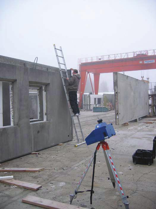
 Press Finish.")
10 4. Measuring (Leap) 4.1 Repositioning (LEAP) Leap The Proliner Leap function was created to give user unlimited range when measuring large objects and spaces. Prodim developed special leap pods, which will be reference points to connect the measurements. Start your measurement as you would do it normally. Position your Proliner on a place where you can reach most of the parts of your object. In that case you need less measurements. When ready with that part, a Leap needs to be defined. When Leap is pressed the leap screen will appear. Here you can either create a new Leap or select to connect to an already defined Leap. You can then measure new leap points or select existing points in the current measurement. After selecting Measure new points you can insert a leap name and then define the points. Press Start Take the 4 points, as accurate as possible with button 1 on your remote Press Finish. Now the Proliner can be moved to the new position to finish the rest of the object. At the new position, start with Leap again. Choose in the dropdown box the Leap to which the drawing needs to be connected and press Connect. Press Start Take the 4 points again, as accurate as possible Check the misfit (If the misfit is within tolerance accept. Otherwise try to measure the leap again) Press Finish. Continue the measurement. These steps can be repeated as often as necessary. There are no limits. Rules of leapfrog measurement: The reference points must be positioned stable. The 4 points should NOT be positioned: 1. Too close to each other 2. In one line 3. In a symmetric shape Prodim CT 3.2 & 3.3 Version Copyright - Prodim International Page Checking CHECK FIRST! Before you start to modify the measurement using any of the Editing (CAD) functions, make sure you have been measuring correctly, by CHECKING the settings. This is particularly important when you are not yet experienced with the Proliner. Below the editing functions, there is a pull out menu that includes Projection, Compensation, Tolerance and Origin. Pan Move the measurement by pressing on the screen and moving it around. Zoom Zoom in by moving down on the screen and zoom out by moving up. Rotate Rotate the measurement by pressing the screen and moving around. Top view The measurement will be shown on top view for the selected layer. View all Shows the measurement exactly fitted on the screen. Display settings Various settings for what is displayed - see next page Projection Selecting this function will allow you to change the projection settings on your Proliner. This is not often changed in a drawings because projection settings are set at the start of the drawing. Compensation This function n will allow you to change your compensation from left to right, or none. It is best to choose the correct projection before starting the measurements. You can change the compensation for a contour, a layer or all. Tolerance Selecting this function will allow you to change the machine s tolerance. The default setting is set to the highest accuracy the Proliner can achieve. Changing the tolerance may result in less accurate drawings and more or fewer points. Origin This function will allow you to set or change the x-axis of the drawing. It is often used to rotate the drawing for easier editing and exporting. To Use: Select the point to go in the lower left corner of the screen or select the point to go in the lower right corner of the screen. Pan Display settings Zoom Top view Rotate View all Prodim CT 3.2 & 3.3 Version Copyright - Prodim International Page 19


11 5. Checking 6. Editing IMPORTANT! You are ready to modify/edit the measurement, we advice you to only to do this once your measurement has been fully completed and the main settings have been thoroughly checked. 6.1 Modification functions Editing and checking drawings with the on-board CAD On-screen Dimensioning * page 17 Measuring page 16 Editing page Import cut-outs (*) page 23 Line Thickness Change the line thickness on screen. Contour Shows you the compensated measured contour. Element Ends Shows the end of every element in a contour. Raw Points Shows the raw 3D points, which are not interpolated and compensated. Dimensions * Shows you the dimensions if you have them applied to the measurement, you can also change the font and arrow sizes of the dimensions Profiles * Shows you the Profiles if you have them applied to the measurement Origin Shows the first measured point of the drawing which is always corresponding with the Origin. Machine Origin Shows the position of the Proliner during the measurement. Drawing page Undo / Redo page 22 Snapshot * page 22 Delete page 22 Information PDF * page Anytime a button has a white triangle in the lower left hand corner, that button has a drop down menu featuring more commands. To access the menu, push and hold down the editing button in that command group. Z-Lines Shows height-lines between the Raw Points and the 2D Contour. Identify First Contour Shows you the first contour as a light grey dashed line Show Leapfrog Shows the points taken for a leapfrog measurement (when present). Click on the to open an example movie of the function. Some of the functions share a movie and the other functions have their own example movie. indicates that there is not yet a movie available for this function. *only available in combination with CT, see chapter 7 Prodim CT 3.2 & 3.3 Version Copyright - Prodim International Page 20 *only available in combination with CT, see chapter 7 Prodim CT 3.2 & 3.3 Version Copyright - Prodim International Page 21

12 6. Editing 6.2 Selection functions The buttons in the selection funstion group are used to select single or multiple elements. The selected data is displayed as a thick red element in the grey toolbar. At the bottom of the screen you can deselect all at once. Multiple elements can be selected and the selected items can be colored, deleted or make snapshots. 6. Editing 6.3 Measuring functions Buttons in the measuring group are used to verify accuracy and check dimensions. The measurement data is always displayed in the grey toolbar at the bottom of the screen. Measurements do not stay on screen when using these measuring buttons. Select element Select contour Select layer Measure line Measure Angle Find Radius Measure Layer Angle Measure Chain Measure Z-Lines Measure Area Select window Select element Touch a single line to select it, touch a selected line to deselect it. Select window Drag over the screen, every complete element within the drag box will be selected. Select contour Touch a line from the contour to select the complete contour at once. Select layer Touch a line from the layer to select the complete layer at once. Prodim CT 3.2 & 3.3 Version Copyright - Prodim International Page 22 Measure line Finds measurements of straight lines. To Use: Touch the end of the first line and touch the end of the second line. Different buttons are available for horizontal, vertical, and point to point dimensions. Find Radius Finds the radius of an arc. To Use: Touch the arc in question. The radius is shown in the grey box at the bottom of the screen. Measure Angle Lets you measure angles. To Use: Select the first line of the angle. Select another line of the angle. The angle is shown in the grey box at the bottom of the screen. Measure Layer Angle Lets you measure the angular difference between two layers. To Use: Select a point on the first layer. Select a point on the second layer. The angle is shown in the grey box at the bottom of the screen. Measure Chain Gives you the square inches of any closed shape on a single layer. To Use: Touch the closed contour in question. The square dimensions are shown in the grey box at the bottom of the screen. Measure Area Gives you the square inches of any closed shape on a single layer. To Use: Touch the closed contour in question. The square dimensions are shown in the grey box at the bottom of the screen. Measure Z-Lines Gives the length of the Z-lines. Shows the distance between actual points gathered and projected points on the layer. To Use: Select the command. This activates the z-lines. Touch the z-line in question. The distance is shown in the grey box at the bottom of the screen. Prodim CT 3.2 & 3.3 Version Copyright - Prodim International Page 23
13 6. Editing 6.4 Editing functions - part 1 Buttons in the editing group all make changes to existing lines. This includes joining, splitting, offsetting different points and lines within your drawings. Trim Fillet 6. Editing 6.5 Editing functions - part 2 Buttons in the editing group all make changes to existing lines. This includes joining, splitting, offsetting different points and lines within your drawings. Tangential Break on intersect Offset points Extend line Offset Split element Modify Radius Layer name Profiles (*) Material (*) Color Trim Extends lines to their intersection and it trims off. To Use: Touch the end of the first line and touch the end of the second line. Fillet Rounds corners to a specific radius. To Use: Touch the end of the first line and touch the end of the Second line. Radius can be changed in the grey menu at the bottom of the screen. Offset Offsets lines to a specific distance. To Use: Touch near the line you want to offset, on the side and the direction you want the offset line. Touch again on the side you want to offset. Distance can be changed in the grey menu at the bottom of the screen. To keep the old line, check the box in the grey menu at the bottom of screen. Split element Splits a line evenly using the number of specified points. To Use: First determine the number of points you need and enter it into the grey menu at the bottom of the screen. Touch the line you want to add the points to. Offset points Splits a line using one point set to a specific distance. To Use: First determine the distance you want to offset the point and enter it into the grey menu at the bottom of the screen. Touch the line near the end you want to offset the point. Break on intersect Uses the intersection of two lines to break one line into two line segments. To Use: Select the line you want to break, then select the line you want to break it with. Tangential Create a perfect target to connect the elements. To Use: Touch the contour point that you want to make tangential. You can set the maximum deviation in the grey menu at the bottom of the screen. Extend line Extends one line so that it will intersect with another line. To Use: Select the line you want to extend, then select the line you want to extend to. Modify radius Tells you the radius of a curve. It also allows you to change the radius. To Use: Select the curve. The radius of the curve is displayed at the bottom of the screen. To change the radius, select the displayed radius and type in your new radius. Color Change the color of the line, contour or layer. To Use: Select the elements that you want to change. In the pop-up menu, choose your color. Then push the apply button. Layer name Change the name of layers in drawing. To Use: Select a line on that layer. Enter the new name. Select apply. *only available in combination with CT, see chapter 7 Prodim CT 3.2 & 3.3 Version Copyright - Prodim International Page 24 Prodim CT 3.2 & 3.3 Version Copyright - Prodim International Page 25
14 6. Editing 6.6 Drawing functions - part 1 Buttons in the drawing group all create new geometry. This includes drawing lines, arcs, circles, rectangles and angles. 6. Editing 6.7 Drawing functions - part 2 Buttons in the drawing group all create new geometry. This includes drawing lines, arcs, circles, rectangles and angles. Line Line perpendicular 2 Point Circle Level Line 3 Point Arc or Circle External Rectangle Draw Line at Angle Rectangle Line Draws lines : horizontal, vertical, or point to point. To Use: Select a point where you want the point to start. Select the point where you want the line to end. In horizontal and vertical settings lines will snap to the correct axis. The axis is based on ORIGIN setting of the drawing. Line perpendicular Draws a line perpendicular to the adjacent line. To Use: Select the start point of your line. Select the line your point is on. Select the line you want the new line to extend to. Draw Line at Angle Draws a line at a specific angle. To Use: Enter the angle in the grey toolbar at the bottom. Select a line to use as a reference. Select a point on that line to act as a start point. Select the side of the line you want the angle to appear on. Level Line (ONLY IN MACHINES EQUIPPED WITH INCLINOMETERS) Draw a line on a drawing that shows a level reference. To Use: Select a start point. Select an end point. The line will be drawn in level to the ground in relation to the rest of the drawing. 3 Point Arc or Circle Uses at least 3 points to create an arc or circle. To Use: Select the start point of the arc. Select the end point of the arc. Select at least one point on the middle of the arc. (To draw a circle check full circle in the grey menu at the bottom of the screen). When finished select Apply. 2 Point Circle Uses 2 points to create a circle (center, radius). To Use: Select the point to be used as a midpoint. Select the point to be used as end of the radius. Select apply. Rectangle Draws a rectangle with specific dimensions. To Use: Enter the width and height in the grey toolbar at the bottom. Touch for location and select apply in the grey toolbar at the bottom. External Rectangle Draws a minimum rectangle around the selected contour specific dimensions. To Use: Select elements and it automatically draws a minimal external box around it. Prodim CT 3.2 & 3.3 Version Copyright - Prodim International Page 26 Prodim CT 3.2 & 3.3 Version Copyright - Prodim International Page 27
15 6. Editing 6.8 Special functions 7. CT MODULE 7.1 OVERVIEW Undo / Redo Snapshot * Undo / Redo Go one step back or forward in your editing, multiple undo s are possible. To Use: Touch to Undo or to redo the a undo. Delete Select single or multiple lines To Use: Select the parts you want to deleted. *only available in combination with CT, see chapter 7 Import cut-out * Delete Information PDF * Complete Technology EXTRA MODULE The Proliner CT Software is available for all Proliner CS and IS Models PRE-PRODUCTION CT is not just editing, but also preparing for production. One measurement transformed in several production pieces. Cutouts, profiles, material. A true output optimized for CNC use. CONNECTION BETWEEN FIELD AND OFFICE The perfect tool to optimize the communication between on-site measuring and the office. Perfect digital templates, additional information and guidance for CAD/CAM, automatic worksheet. All you need to avoid mistake and time-loss. To make the most of the Proliner technology. BASIC FUNCTIONALITIES 1. EXTRA CAD functionalities Specifically designed for the templating industries. Dimensions and Text Labels on the measurement. 2. CUT-OUTS You can insert cutouts (in the field) out of customizable libraries. Cutouts that you have inserted will be recognized and saved in the output. You can also add cutouts you just digitize on the spot, using the Proliner. 3. PROFILES You can insert on spot profiles (edges) out of customizable libraries. They can be recognized by CAD and CAM software, cutting down editing effort. 4. MATERIALS When already known, materials can be specified while or after measuring. 5. INFORMATION (PROJECT and MEASUREMENT) An extra layer of information, because it is not only about a shape, but also about how to interpret and process it. Custom fields can be easily set to fit all companies and all procedures. 6. WORKSHEET (PDF REPORT) An automatic worksheet contains all the shapes and information (as mentioned above) generated and exported as PDF Report. The ideal integration to the DXF files, can be used for: o Order confirmation, in your administratio o In your office as CAD file o In production as a way to verify the cutting machine operations Prodim CT 3.2 & 3.3 Version Copyright - Prodim International Page 28 Prodim CT 3.2 & 3.3 Version Copyright - Prodim International Page 29

16 7. CT MODULE - EDITING 7.2 Editing On-screen dimensioning 7. CT MODULE - EDITING 7.2 Editing CT Specials: Profile and Material Buttons in the on-screen dimensioning group are used to put visible data on your drawing. These dimensions will be visible on the PDF document exported from the Proliner. Buttons in the editing group all make changes to existing lines. This includes joining, splitting, offsetting different points and lines within your drawings. Line Dimensioning Radius Dimensioning Angle Dimensioning Line Dimensioning Puts measurements of straight lines on-screen. To Use: Touch the end of the first line and touch the end of the Second line. The third spot you will touch is the area where you want the measurement displayed. Different buttons are available for horizontal, vertical, and point to point dimensions. Radius Dimensioning Puts measurements of radii on-screen. To Use: Touch the radius line needed. Touch the area where you want the measurement displayed. Angle Dimensioning Puts measurements of angles on-screen. To Use: Touch the first line making the angle. Second, select the second line of the angle. Touch the area where you want the measurement displayed. Profiles Material Profiles Add a profile to the parts of your measurement. To Use: In the pop-up menu, choose your profile. Then push the Oke button. Select the elements that you want to change. Profiles are setup in Prodim software running on the PC. Profiles have names, colors and line thickness. Used Profiles will show up in a legend on the PDF worksheet page. Material Add a material to your measurement. To Use: In the pop-up menu, choose your material. Then push the Oke button. Select the elements that you want to change. Material are setup in Host software running on the PC. Selected Material will show up in a legend on the PDF worksheet page. Prodim CT 3.2 & 3.3 Version Copyright - Prodim International Page 30 Prodim CT 3.2 & 3.3 Version Copyright - Prodim International Page 31


17 7. CT MODULE - Editing 7.2 Editing Drawing functions 7. CT MODULE - Editing 7.2 Editing Inserting and Reporting functions Buttons in the drawing group all create new geometry. This includes drawing lines, arcs, circles, rectangles and angles. Import cut-out Undo / Redo Delete Create a Sketch Information PDF External Rectangle Backsplash Import cut-out Import a PRL file (Proliner file) or DXF file in your current measurement. This function will be completely explained below in a dedicated paragraph. Bump-out Rectangle Bump-out Creates a bump-out at a specific distance using any 2 start points. To Use: Insert the desired distance in the grey bar at the bottom of the screen. Select the first start point. Select the second point (ending point). Touch the area of the screen you want the bump-out to appear. Backsplash Creates backsplash using any two points of the drawing. To Use: Insert the desired height in the grey bar at the bottom of the screen. Select the first start point. Select the second point (ending point). Selecting points in the same order they were measured puts the backsplash in the correct location in the drawing. If the backsplash appears on the wrong side, undo and select points in the opposite order. This function will be completely explained below in a dedicated paragraph. Create a Sketch Create a snapshot to create PDF worksheets. To Use: Select the elements you want for your single snapshot, for example select lines, contours and dimensions. Touch the snapshot button and fill in the name of the snapshot in the pop-up, click Oke. Information PDF Access your PDF worksheet pages. In the PDF information menu you can access all the snapshots made (multiple snapshots possible), add / edit project and measurement information. You can setup the exploded view and save options. This function will be completely explained below in a dedicated paragraph. Rectangle Draws a rectangle with specific dimensions. To Use: Enter the width and height in the grey toolbar at the bottom. Touch for location and select apply in the grey toolbar at the bottom. External Rectangle Draws a minimum rectangle around the selected contour specific dimensions. To Use: Select elements and it automatically draws a minimal external box around it. Prodim CT 3.2 & 3.3 Version Copyright - Prodim International Page 32 Prodim CT 3.2 & 3.3 Version Copyright - Prodim International Page 33


18 7. CT MODULE - Editing Import cut-out Library Object Import Placement Method 7. CT MODULE - Sketch 7.3 Sketch - Sketch List INFORMATION By pressing on this symbol, in the main Editing screen, you can report information and create a worksheet. There are 3 steps: 1. Confirm/Edit production pieces in Sketch List 2. Check details, add information (project, measurement) and Sign-Off 3. Preview the PDF report SKETCH LIST You can use the Sketch List to rename a piece and to preview it. In the Sketch List there are some options, customizable for each sketch : - EXPORT : to export the piece as a stand alone, CNC ready, DXF file - PDF : to save its own page in the PDF report - EXPLODED VIEW : to add the piece to the exploded view, which serves as first page of the report that can be output as DXF Offset All options are tagged and on by default. Production Pieces (Sketches List) Sketch preview Sketch Editing Color Preview Sketch (Production piece) The single part of the overall measurement that you selected and idendity as a prodiction piece. Browsing Library Pull-down menu which can contain multiple premade libraries with cut-outs to select from. Object Pull-down menu with the cut-outs that are present in the selected library. Import Instead of using a library you can also import a PRL file or DXF file from the Proliner or USB. Placement method Place a selected cut-out onto a centerline or use reference points to place the cut-out. Offset (centerline only) When using the centerline method you can set the distance from the front, this can be changed after importing in the grey bottom box, when using the reference points method you can move the imported object freely. Color Select the color you want the imported object to have in the measurement. Preview Shows you a preview of the object that you are going to import. Placing the object in the measurement After pressing Oke for location, select apply in the grey toolbar at the bottom. Before selecting apply you can move and rotate the object by selecting the option in the grey toolbar at the bottom. Exploded view Shows all the selected sketches on one single view. it serves also as first page of the PDF Report. You can move the pieces around, arranging them as you like. it can be exported as DXF to deal with only one output for all sketches. Browsing There are further information to be added, before you can create and outut the worksheets. Browse through the CT reporting functionalities by using the arrow on the side bar. Prodim CT 3.2 & 3.3 Version Copyright - Prodim International Page 34 Prodim CT 3.2 & 3.3 Version Copyright - Prodim International Page 35
 and Sign-Off Selection Identify the item you want to delete, move, or edit.")

 Add dimensions (linear : horizontal, vertical, point2point) on the sketch itself SELECT Identify the item you want to delete, move, or edit.")
 or MINUS (-) signs.")


19 7. CT MODULE - Sketch 7.3 Sketch - Editing a Sketch 7. CT MODULE - Report (PDF) 7.4 Report - Info INFORMATION Check details, add information (project, measurement) and Sign-Off Selection Identify the item you want to delete, move, or edit. Freehand sketch When you have opened a snapshot you can use this pen to draw extra information. Touch the snapshot button and fill in the name. Delete elements Go one step back or forward in your editing, multiple undo s are possible. To Use: Press Undo to undo or to redo. Text Label Select the name and the exported DXF file of the snapshot Drag a rectangle to create a Text Box. Type the text using the virtual keyboard. Dimensions (for Sketch) Add dimensions (linear : horizontal, vertical, point2point) on the sketch itself SELECT Identify the item you want to delete, move, or edit. The item will be boxed and highlighted in green. MOVE You can move items around using the 4 directions arrow. INCREASE/DECREASE If an object is not well visualized, select it and then increase the box size by pressing PLUS (+) or MINUS (-) signs. Details Reminder of all measurement information Cutouts, Profiles, Material Project Project information is shown on the PDF worksheet. Preview of the PDF worksheet is shown on page 27. Add or edit the information about the Project, such as the customer s name and address and operator. Measurement Measurement information is shown on the PDF worksheet. Preview of the PDF worksheet is shown on page 27. Add or edit the information about the Project, such as material, parts and remarks. Sketches Gives you the main PDF information page, as shown above. Signature The Signature is shown on the PDF worksheet. With this function you can add disclaimer information and name. (You can let the client sign off a project immediately on the Proliner). PDF preview PDF worksheet pages. Shows you how the PDF worksheet will look like when its created. Note: the movie will show the complete PDF information function Prodim CT 3.2 & 3.3 Version Copyright - Prodim International Page 36 Prodim CT 3.2 & 3.3 Version Copyright - Prodim International Page 37
 or via")

 * Format: DXF It will create separate files, one for each production piece.")
, XML/TXT (without CT) The PDF report is effectively a worksheets containing that can")
20 7. CT MODULE - Report (PDF) 7.4 Sketch - Report Preview 8. Transfer 8.1 Transfer Screen Different PDF pages Transfering You can browse the Proliner memory and choose files to be transfered via USB (standard) or via ETHERNET CABLE (optional). 8.2 Transfer Output The most common outputs are : Project information Customer signature Measurement information Exploded view OVERALL MEASUREMENT Available in all Proliner Formats: DXF, PRL8 (by default), TXT (optional). The overall measurement as created by the standard Proliner,.PRL8 is a backup file. SKETCHES (PRODUCTION PIECES) * Format: DXF It will create separate files, one for each production piece. This output is optimized for being processed by a CAM program. PDF preview Snapshot specific page REPORT * Format: PDF (with CT), XML/TXT (without CT) The PDF report is effectively a worksheets containing that can be used in administration, production and as attachment to invoices. XML/TXT will contain simple notes, written by devices not equipped with CT. *only available in combination with CT Prodim CT 3.2 & 3.3 Version Copyright - Prodim International Page 38 Prodim CT 3.2 & 3.3 Version Copyright - Prodim International Page 39

 OUTPUT Contours/Profiles: lines with profile specifications Exploded view : all the sketches in one file FORMAT Only Lines and")


21 8. Transfer 8.3 Transfer settings MEASUREMENT OUTPUT Contours: Interpolated black lines Raw Lines: original 3D entites Machine Origin: Proliner position Z-lines : projections lines (from 3D to 2D) Level-symbol : water-leveled plane (if inclino) FORMAT You can opt between different DXF formats SKETCHES (PRODUCTION PIECES) OUTPUT Contours/Profiles: lines with profile specifications Exploded view : all the sketches in one file FORMAT Only Lines and Arcs available TEXT FORMAT If Sketches are set to have text in the output, then size and spacing can be set in here. 9. Tips Maintenance General Care The Proliner is a tough machine but it is still recommendable to keep a good care of it at any given time. We advice to keep the Proliner machine clean and out of dust, also when storing. If possible, make use of official backpack and/or flight case. Accessories Proliner Accessories There are many accessories that can improve your Proliner experience even further. Please contact Prodim to explain your specific needs and we will offer you the most suitable solution. Proliner courses If you want to increase your Proliner knowledge to challenge yourself with new application or more complex projects, consider a Proliner course. Prodim can offer them in our Training Centers or also via web! Easy, quick and efficient. Contacts Technical and Commercial assistance If you have questions, feedback or if you want to purchase a training, please contact the Prodim office closest to your location. You can locate it and contact it using information on our official website: Prodim CT 3.2 & 3.3 Version Copyright - Prodim International Page 40 Prodim CT 3.2 & 3.3 Version Copyright - Prodim International Page 41

22 Prodim International BV Lagedijk BZ Helmond, Nederland T: a product of
PRODIM CT 3.0 MANUAL the complete solution
 PRODIM CT 3.0 MANUAL the complete solution We measure it all! General information Copyright All rights reserved. Apart from the legally laid down exceptions, no part of this publication may be reproduced,
Introduction to Sheet Metal Features SolidWorks 2009
 SolidWorks 2009 Table of Contents Introduction to Sheet Metal Features Base Flange Method Magazine File.. 3 Envelopment & Development of Surfaces.. 14 Development of Transition Pieces.. 23 Conversion to
The Revolve Feature and Assembly Modeling
 The Revolve Feature and Assembly Modeling PTC Clock Page 52 PTC Contents Introduction... 54 The Revolve Feature... 55 Creating a revolved feature...57 Creating face details... 58 Using Text... 61 Assembling
Kitchen and Bath Design Tutorial
 Kitchen and Bath Design Tutorial This tutorial continues where the Interior Design Tutorial left off. You should save this tutorial using a new name to archive your previous work. The tools and techniques
Kitchen and Bath Design Tutorial
 Kitchen and Bath Design Tutorial This tutorial continues where the Interior Design Tutorial left off. You should save this tutorial using a new name to archive your previous work. The tools and techniques
Lesson 6 2D Sketch Panel Tools
 Lesson 6 2D Sketch Panel Tools Inventor s Sketch Tool Bar contains tools for creating the basic geometry to create features and parts. On the surface, the Geometry tools look fairly standard: line, circle,
SolidWorks 95 User s Guide
 SolidWorks 95 User s Guide Disclaimer: The following User Guide was extracted from SolidWorks 95 Help files and was not originally distributed in this format. All content 1995, SolidWorks Corporation Contents
SolidWorks Part I - Basic Tools SDC. Includes. Parts, Assemblies and Drawings. Paul Tran CSWE, CSWI
 SolidWorks 2015 Part I - Basic Tools Includes CSWA Preparation Material Parts, Assemblies and Drawings Paul Tran CSWE, CSWI SDC PUBLICATIONS Better Textbooks. Lower Prices. www.sdcpublications.com Powered
AEROPLANE. Create a New Folder in your chosen location called Aeroplane. The four parts that make up the project will be saved here.
 AEROPLANE Prerequisite Knowledge Previous knowledge of the following commands is required to complete this lesson. Sketching (Line, Rectangle, Arc, Add Relations, Dimensioning), Extrude, Assemblies and
Learning Guide. ASR Automated Systems Research Inc. # Douglas Crescent, Langley, BC. V3A 4B6. Fax:
 Learning Guide ASR Automated Systems Research Inc. #1 20461 Douglas Crescent, Langley, BC. V3A 4B6 Toll free: 1-800-818-2051 e-mail: support@asrsoft.com Fax: 604-539-1334 www.asrsoft.com Copyright 1991-2013
How to Build a Game Console. David Hunt, PE
 How to Build a Game Console David Hunt, PE davidhunt@outdrs.net Covering: Drafts Fillets Shells Patterns o Linear o Circular Using made-for-the-purpose sketches to define reference geometry Using reference
User Guide V10 SP1 Addendum
 Alibre Design User Guide V10 SP1 Addendum Copyrights Information in this document is subject to change without notice. The software described in this document is furnished under a license agreement or
Architecture 2012 Fundamentals
 Autodesk Revit Architecture 2012 Fundamentals Supplemental Files SDC PUBLICATIONS Schroff Development Corporation Better Textbooks. Lower Prices. www.sdcpublications.com Tutorial files on enclosed CD Visit
Activity 1 Modeling a Plastic Part
 Activity 1 Modeling a Plastic Part In this activity, you will model a plastic part. When completed, your plastic part should look like the following two illustrations. While building this model, take time
Drawing with precision
 Drawing with precision Welcome to Corel DESIGNER, a comprehensive vector-based drawing application for creating technical graphics. Precision is essential in creating technical graphics. This tutorial
House Design Tutorial
 House Design Tutorial This House Design Tutorial shows you how to get started on a design project. The tutorials that follow continue with the same plan. When you are finished, you will have created a
Introduction to Autodesk Inventor for F1 in Schools (Australian Version)
") Introduction to Autodesk Inventor for F1 in Schools (Australian Version) F1 in Schools race car In this course you will be introduced to Autodesk Inventor, which is the centerpiece of Autodesk s Digital
Introduction to Autodesk Inventor for F1 in Schools (Australian Version) F1 in Schools race car In this course you will be introduced to Autodesk Inventor, which is the centerpiece of Autodesk s Digital
Siemens NX11 tutorials. The angled part
 Siemens NX11 tutorials The angled part Adaptation to NX 11 from notes from a seminar Drive-to-trial organized by IBM and GDTech. This tutorial will help you design the mechanical presented in the figure
Using Siemens NX 11 Software. The connecting rod
 Using Siemens NX 11 Software The connecting rod Based on a Catia tutorial written by Loïc Stefanski. At the end of this manual, you should obtain the following part: 1 Introduction. Start NX 11 and open
House Design Tutorial
 House Design Tutorial This House Design Tutorial shows you how to get started on a design project. The tutorials that follow continue with the same plan. When you are finished, you will have created a
Chapter 6 Title Blocks
 Chapter 6 Title Blocks In previous exercises, every drawing started by creating a number of layers. This is time consuming and unnecessary. In this exercise, we will start a drawing by defining layers
Revit Structure 2012 Basics:
 SUPPLEMENTAL FILES ON CD Revit Structure 2012 Basics: Framing and Documentation Elise Moss autodesk authorized publisher SDC PUBLICATIONS www.sdcpublications.com Schroff Development Corporation Structural
Constructing a Wedge Die
 1-(800) 877-2745 www.ashlar-vellum.com Using Graphite TM Copyright 2008 Ashlar Incorporated. All rights reserved. C6CAWD0809. Ashlar-Vellum Graphite This exercise introduces the third dimension. Discover
Sketch-Up Guide for Woodworkers
 W Enjoy this selection from Sketch-Up Guide for Woodworkers In just seconds, you can enjoy this ebook of Sketch-Up Guide for Woodworkers. SketchUp Guide for BUY NOW! Google See how our magazine makes you
Inventor-Parts-Tutorial By: Dor Ashur
 Inventor-Parts-Tutorial By: Dor Ashur For Assignment: http://www.maelabs.ucsd.edu/mae3/assignments/cad/inventor_parts.pdf Open Autodesk Inventor: Start-> All Programs -> Autodesk -> Autodesk Inventor 2010
Module 1G: Creating a Circle-Based Cylindrical Sheet-metal Lateral Piece with an Overlaying Lateral Edge Seam And Dove-Tail Seams on the Top Edge
 Inventor (10) Module 1G: 1G- 1 Module 1G: Creating a Circle-Based Cylindrical Sheet-metal Lateral Piece with an Overlaying Lateral Edge Seam And Dove-Tail Seams on the Top Edge In Module 1A, we have explored
Digital Camera Exercise
 Commands Used New Part This lesson includes Sketching, Extruded Boss/Base, Extruded Cut, Fillet, Chamfer and Text. Click File, New on the standard toolbar. Select Part from the New SolidWorks Document
Advance Dimensioning and Base Feature Options
 Chapter 4 Advance Dimensioning and Base Feature Options Learning Objectives After completing this chapter you will be able to: Dimension the sketch using the autodimension sketch tool. Dimension the sketch
Introduction to SolidWorks Introduction to SolidWorks
 Introduction to SolidWorks Introduction to SolidWorks SolidWorks is a powerful 3D modeling program. The models it produces can be used in a number of ways to simulate the behaviour of a real part or assembly
Beginner s Guide to SolidWorks Alejandro Reyes, MSME Certified SolidWorks Professional and Instructor SDC PUBLICATIONS
 Beginner s Guide to SolidWorks 2008 Alejandro Reyes, MSME Certified SolidWorks Professional and Instructor SDC PUBLICATIONS Schroff Development Corporation www.schroff.com www.schroff-europe.com Part Modeling
House Design Tutorial
 Chapter 2: House Design Tutorial This House Design Tutorial shows you how to get started on a design project. The tutorials that follow continue with the same plan. When you are finished, you will have
Engineering Technology
 Engineering Technology Introduction to Parametric Modelling Engineering Technology 1 See Saw Exercise Part 1 Base Commands used New Part This lesson includes Sketching, Extruded Boss/Base, Hole Wizard,
Module 2: Radial-Line Sheet-Metal 3D Modeling and 2D Pattern Development: Right Cone (Regular, Frustum, and Truncated)
") Inventor (5) Module 2: 2-1 Module 2: Radial-Line Sheet-Metal 3D Modeling and 2D Pattern Development: Right Cone (Regular, Frustum, and Truncated) In this tutorial, we will learn how to build a 3D model
Inventor (5) Module 2: 2-1 Module 2: Radial-Line Sheet-Metal 3D Modeling and 2D Pattern Development: Right Cone (Regular, Frustum, and Truncated) In this tutorial, we will learn how to build a 3D model
Toothbrush Holder. A drawing of the sheet metal part will also be created.
 Prerequisite Knowledge Previous knowledge of the following commands is required to complete this lesson; Sketch (Line, Centerline, Circle, Add Relations, Smart Dimension,), Extrude Boss/Base, and Edit
House Design Tutorial
 Chapter 2: House Design Tutorial This House Design Tutorial shows you how to get started on a design project. The tutorials that follow continue with the same plan. When you are finished, you will have
Introduction to Circular Pattern Flower Pot
 Prerequisite Knowledge Previous knowledge of the sketching commands Line, Circle, Add Relations, Smart Dimension is required to complete this lesson. Previous examples of Revolved Boss/Base, Cut Extrude,
AreaSketch Pro Overview for ClickForms Users
 AreaSketch Pro Overview for ClickForms Users Designed for Real Property Specialist Designed specifically for field professionals required to draw an accurate sketch and calculate the area and perimeter
1: INTRODUCTION TO AUTOCAD
 AutoCAD syllabus 1: INTRODUCTION TO AUTOCAD Starting AutoCAD AutoCAD Screen Components Drawing Area Command Window Navigation bar Status bar Invoking Commands in AutoCAD Keyboard Ribbon Application Menu
Revit Structure 2013 Basics
 Revit Structure 2013 Basics Framing and Documentation Elise Moss Supplemental Files SDC P U B L I C AT I O N S Schroff Development Corporation Better Textbooks. Lower Prices. www.sdcpublications.com Tutorial
Module 1H: Creating an Ellipse-Based Cylindrical Sheet-metal Lateral Piece
 Inventor (10) Module 1H: 1H- 1 Module 1H: Creating an Ellipse-Based Cylindrical Sheet-metal Lateral Piece In this Module, we will learn how to create an ellipse-based cylindrical sheetmetal lateral piece
Anna Gresham School of Landscape Design. CAD for Beginners. CAD 3: Using the Drawing Tools and Blocks
 Anna Gresham School of Landscape Design CAD for Beginners CAD 3: Using the Drawing Tools and Blocks Amended for DraftSight V4 October 2013 INDEX OF TOPICS for CAD 3 Pages ESnap 3-5 Essential drawing tools
Getting Started. with Easy Blue Print
 Getting Started with Easy Blue Print User Interface Overview Easy Blue Print is a simple drawing program that will allow you to create professional-looking 2D floor plan drawings. This guide covers the
Kitchen and Bath Design Tutorial
 Kitchen and Bath Design Tutorial This tutorial continues where the Interior Design Tutorial left off. You should save this tutorial using a new name to archive your previous work. The tools and techniques
CAD Tutorial 24: Step by Step Guide
 CAD TUTORIAL 24: Step by step CAD Tutorial 24: Step by Step Guide Level of Difficulty Time Approximately 40 50 minutes Lesson Objectives To understand the basic tools used in SketchUp. To understand the
CAD/CAM Lamp Project using 2D Design and the X-660 Laser Cutter
 CAD/CAM Lamp Project using 2D Design and the X-660 Laser Cutter Paul Tate 2008 Booklet Version 2 Getting Started the preliminaries The Laser cutter which is going to cut out your acrylic bases and polypropylene
S206E Lecture 6, 5/18/2016, Rhino 3D Architectural Modeling an overview
 Copyright 2016, Chiu-Shui Chan. All Rights Reserved. S206E057 Spring 2016 This tutorial is to introduce a basic understanding on how to apply visual projection techniques of generating a 3D model based
Alternatively, the solid section can be made with open line sketch and adding thickness by Thicken Sketch.
 Sketcher All feature creation begins with two-dimensional drawing in the sketcher and then adding the third dimension in some way. The sketcher has many menus to help create various types of sketches.
Activity 5.2 Making Sketches in CAD
 Activity 5.2 Making Sketches in CAD Introduction It would be great if computer systems were advanced enough to take a mental image of an object, such as the thought of a sports car, and instantly generate
with Creo Parametric 4.0
 Parametric Modeling with Creo Parametric 4.0 An Introduction to Creo Parametric 4.0 NEW Contains a new chapter on 3D Printing Randy H. Shih SDC PUBLICATIONS Better Textbooks. Lower Prices. www.sdcpublications.com
ILLUSTRATOR BASICS FOR SCULPTURE STUDENTS. Vector Drawing for Planning, Patterns, CNC Milling, Laser Cutting, etc.
 ILLUSTRATOR BASICS FOR SCULPTURE STUDENTS Vector Drawing for Planning, Patterns, CNC Milling, Laser Cutting, etc. WELCOME TO THE ILLUSTRATOR TUTORIAL FOR SCULPTURE DUMMIES! This tutorial sets you up for
SOLIDWORKS 2015 and Engineering Graphics
 SOLIDWORKS 2015 and Engineering Graphics An Integrated Approach Randy H. Shih SDC PUBLICATIONS Better Textbooks. Lower Prices. www.sdcpublications.com Powered by TCPDF (www.tcpdf.org) Visit the following
Module 1C: Adding Dovetail Seams to Curved Edges on A Flat Sheet-Metal Piece
 1 Module 1C: Adding Dovetail Seams to Curved Edges on A Flat Sheet-Metal Piece In this Module, we will explore the method of adding dovetail seams to curved edges such as the circumferential edge of a
SolidWorks Design & Technology
 SolidWorks Design & Technology Training Course at PHSG Ex 5. Lego man Working with part files 8mm At first glance the Lego man looks complicated but I hope you will see that if you approach a project one
Product Modelling in Solid Works
 Product Modelling in Solid Works In the following exercise you will use solid works to construct the computer mouse shown opposite. In this exercise you will use a number of advanced features to achieve
House Design Tutorial
 Chapter 2: House Design Tutorial This House Design Tutorial shows you how to get started on a design project. The tutorials that follow continue with the same plan. When we are finished, we will have created
Roof Tutorial Wall Specification
 Roof Tutorial The majority of Roof Tutorial describes some common roof styles that can be created using settings in the Wall Specification dialog and can be completed independent of the other tutorials.
AutoCAD Tutorial First Level. 2D Fundamentals. Randy H. Shih SDC. Better Textbooks. Lower Prices.
 AutoCAD 2018 Tutorial First Level 2D Fundamentals Randy H. Shih SDC PUBLICATIONS Better Textbooks. Lower Prices. www.sdcpublications.com Powered by TCPDF (www.tcpdf.org) Visit the following websites to
and Engineering Graphics
 SOLIDWORKS 2018 and Engineering Graphics An Integrated Approach Randy H. Shih SDC PUBLICATIONS Better Textbooks. Lower Prices. www.sdcpublications.com Powered by TCPDF (www.tcpdf.org) Visit the following
CREO.1 MODELING A BELT WHEEL
 CREO.1 MODELING A BELT WHEEL Figure 1: A belt wheel modeled in this exercise. Learning Targets In this exercise you will learn: Using symmetry when sketching Using pattern to copy features Using RMB when
Modeling an Airframe Tutorial
 EAA SOLIDWORKS University p 1/11 Difficulty: Intermediate Time: 1 hour As an Intermediate Tutorial, it is assumed that you have completed the Quick Start Tutorial and know how to sketch in 2D and 3D. If
Part 6: Checking an existing kitchen design
 Welcome, Thank you for choosing, an innovative surveying tool for kitchen surveying. To help you get started with, we will guide you on the following pages through the registration, installation and handling
QUICKSTART COURSE - MODULE 1 PART 2
 QUICKSTART COURSE - MODULE 1 PART 2 copyright 2011 by Eric Bobrow, all rights reserved For more information about the QuickStart Course, visit http://www.acbestpractices.com/quickstart Hello, this is Eric
Chapter 2. Drawing Sketches for Solid Models. Learning Objectives
 Chapter 2 Drawing Sketches for Solid Models Learning Objectives After completing this chapter, you will be able to: Start a new template file to draw sketches. Set up the sketching environment. Use various
SMALL OFFICE TUTORIAL
 SMALL OFFICE TUTORIAL in this lesson you will get a down and dirty overview of the functionality of Revit Architecture. The very basics of creating walls, doors, windows, roofs, annotations and dimensioning.
Apple Photos Quick Start Guide
 Apple Photos Quick Start Guide Photos is Apple s replacement for iphoto. It is a photograph organizational tool that allows users to view and make basic changes to photos, create slideshows, albums, photo
ARCHLine.XP Interior Windows. Learning Interior. Learning material for the basics of ARCHLine.XP Interior. ARCHLine.
 ARCHLine.XP Interior 2010 Windows Learning Interior Learning material for the basics of ARCHLine.XP Interior ARCHLine.XP Interior Information in this document is subject to change without notice and does
Foreword. If you have any questions about these tutorials, drop your mail to
 Foreword The main objective of these tutorials is to give you a kick start using Solidworks. The approach to write this tutorial is based on what is the most important knowledge you should know and what
Part 8: The Front Cover
 Part 8: The Front Cover 4 Earpiece cuts and housing Lens cut and housing Microphone cut and housing The front cover is similar to the back cover in that it is a shelled protrusion with screw posts extruding
ORTHOGRAPHIC PROJECTIONS. Ms. Sicola
 ORTHOGRAPHIC PROJECTIONS Ms. Sicola Objectives List the six principal views of projection Sketch the top, front and right-side views of an object with normal, inclined, and oblique surfaces Objectives
Revit Structure 2014 Basics
 Revit Structure 2014 Basics Framing and Documentation Elise Moss Authorized Author SDC P U B L I C AT I O N S Better Textbooks. Lower Prices. www.sdcpublications.com Powered by TCPDF (www.tcpdf.org) Visit
Main screen of ipocket Draw
 Main screen of ipocket Draw The tools of "management" Informations on the drawing and the softaware Display/Hide and settings of the grid (with a 2x tap) Drawing tools and adjustment tools The tools with..
EASY CNC. Table of Contents
 Square 1 Electronics announces its new book by David Benson, "Easy CNC", A Beginner's Guide to CNC" The complete table of contents follows: This book was written by David Benson (8-1/2 x 11", 200 pages,
Table of Contents. Lesson 1 Getting Started
 NX Lesson 1 Getting Started Pre-reqs/Technical Skills Basic computer use Expectations Read lesson material Implement steps in software while reading through lesson material Complete quiz on Blackboard
for Solidworks TRAINING GUIDE LESSON-9-CAD
 for Solidworks TRAINING GUIDE LESSON-9-CAD Mastercam for SolidWorks Training Guide Objectives You will create the geometry for SolidWorks-Lesson-9 using SolidWorks 3D CAD software. You will be working
Draw IT 2016 for AutoCAD
 Draw IT 2016 for AutoCAD Tutorial for System Scaffolding Version: 16.0 Copyright Computer and Design Services Ltd GLOBAL CONSTRUCTION SOFTWARE AND SERVICES Contents Introduction... 1 Getting Started...
Lesson 4 Extrusions OBJECTIVES. Extrusions
 Lesson 4 Extrusions Figure 4.1 Clamp OBJECTIVES Create a feature using an Extruded protrusion Understand Setup and Environment settings Define and set a Material type Create and use Datum features Sketch
Release Notes - Fixes in Tekla Structures 2016i SP1
 Release Notes - Fixes in Tekla Structures 2016i SP1 is modified., the ID of the connection plate is not changed anymore when the connection now uses normal rebar groups instead of tapered groups., the
Evaluation Chapter by CADArtifex
 The premium provider of learning products and solutions www.cadartifex.com EVALUATION CHAPTER 2 Drawing Sketches with SOLIDWORKS In this chapter: Invoking the Part Modeling Environment Invoking the Sketching
Making Standard Note Blocks and Placing the Bracket in a Drawing Border
 C h a p t e r 12 Making Standard Note Blocks and Placing the Bracket in a Drawing Border In this chapter, you will learn the following to World Class standards: Making standard mechanical notes Using the
MasterCAM for Dresser Valet
 MasterCAM for Dresser Valet Check to make sure the nethasp is working/turned on to network. Go to ALL APPs/Mastercam x8/nethasp After the computer reads the nethasp, these programs should show up. If not
Dimensioning the Rectangular Problem
 C h a p t e r 3 Dimensioning the Rectangular Problem In this chapter, you will learn the following to World Class standards: 1. Creating new layers in an AutoCAD drawing 2. Placing Centerlines on the drawing
Tutorial Building the Nave Arcade
 Tutorial: Digital Gothic AH C117B (Winter 2017) Tutorial Building the Nave Arcade Overview: Step 1: Determining and Drawing The Arch (Quinto Arch) Step 2: Extrude Molding Profile Step 3: Adding Walls Step
Release Notes - Fixes in Tekla Structures 2016i PR1
 Release Notes - Fixes in Tekla Structures 2016i PR1, you can now set the to either or. is modified., the ID of the connection plate is not changed anymore when the connection now uses normal rebar groups
Sash Clamp. Sash Clamp SW 2015 Design & Communication Graphics Page 1.
 Sash Clamp 1 Introduction: The Sash clamp consists of nine parts. In creating the clamp we will be looking at the improvements made by SolidWorks in linear patterns, adding threads and in assembling the
FUSION 360: SKETCHING FOR MAKERS
 FUSION 360: SKETCHING FOR MAKERS LaDeana Dockery 2017 MAKEICT Wichita, KS 1 Table of Contents Interface... 1 File Operations... 1 Opening Existing Models... 1 Mouse Navigation... 1 Preferences... 2 Navigation
Ornamental Pro 2004 Instruction Manual (Drawing Basics)
") Ornamental Pro 2004 Instruction Manual (Drawing Basics) http://www.ornametalpro.com/support/techsupport.htm Introduction Ornamental Pro has hundreds of functions that you can use to create your drawings.
Ornamental Pro 2004 Instruction Manual (Drawing Basics) http://www.ornametalpro.com/support/techsupport.htm Introduction Ornamental Pro has hundreds of functions that you can use to create your drawings.
ACAD-BAU TUTORIAL For BricsCAD platform
 ACAD-BAU TUTORIAL WWW.ARHINOVA.SI For BricsCAD platform August 06 WORKSPACE ACAD-BAU RIBBON ACAD-BAU CONTROL BAR F ACAD-BAU PALETTES BASIC SETTINGS Use New command and open the template called ACB_International.DWT.
1. Creating geometry based on sketches 2. Using sketch lines as reference 3. Using sketches to drive changes in geometry
 4.1: Modeling 3D Modeling is a key process of getting your ideas from a concept to a read- for- manufacture state, making it core foundation of the product development process. In Fusion 360, there are
Drawing a Living Room and Family Room Floorplan
 Appendix C Drawing a Living Room and Family Room Floorplan In this chapter, you will learn the following to World Class standards: Draw a Living Room and Family Room Floorplan Draw the Walls and Stairs
SDC. SolidWorks Tutorial 2001Plus. A Competency Project Based Approach Utilizing 3D Solid Modeling. David C. Planchard & Marie P.
 2001Plus A Competency Project Based Approach Utilizing 3D Solid Modeling David C. Planchard & Marie P. Planchard SDC PUBLICATIONS www.schroff.com www.schroff-europe.com Project 2 Below are the desired
Copyrighted Material. Copyrighted Material. Copyrighted. Copyrighted. Material
 Engineering Graphics ORTHOGRAPHIC PROJECTION People who work with drawings develop the ability to look at lines on paper or on a computer screen and "see" the shapes of the objects the lines represent.
33-2 Satellite Takeoff Tutorial--Flat Roof Satellite Takeoff Tutorial--Flat Roof
 33-2 Satellite Takeoff Tutorial--Flat Roof Satellite Takeoff Tutorial--Flat Roof A RoofLogic Digitizer license upgrades RoofCAD so that you have the ability to digitize paper plans, electronic plans and
Autodesk Inventor Module 17 Angles
 Inventor Self-paced ecourse Autodesk Inventor Module 17 Angles Learning Outcomes When you have completed this module, you will be able to: 1 Describe drawing inclined lines, aligned and angular dimensions,
VTube-LASER Quick Start Guide
 VTube-LASER Quick Start Guide This guide shows how to import a STEP file and then MEASURE and qualify demo tube 4 using the standard UNISCAN method of measuring. The steps in this workflow are from version
DRAFT Solid Edge ST4 Update Training Draft
 DRAFT Solid Edge ST4 Update Training Draft Presented by: Steve Webb Topics Parts List Table Titles Column Headers Headers Merging Header Rotate Cell Aspect Ratio Cell Formatting Overriding Disabled Cells
ISCapture User Guide. advanced CCD imaging. Opticstar
 advanced CCD imaging Opticstar I We always check the accuracy of the information in our promotional material. However, due to the continuous process of product development and improvement it is possible