Greenlining and Bluelining of Ergon Energy Substation Drawings
|
|
|
- Rose Melton
- 6 years ago
- Views:
Transcription
1 Greenlining and Bluelining of Ergon Energy
2 Table of Contents Purpose and Scope... 1 Responsibilities... 1 Definitions, Abbreviations and Acronyms... 1 References... 1 General... 1 Requirements... 3 Testing Notes... 3 Method... 4 Continuity Test Example... 4 Control Cable Testing... 9 Cable Schedule... 9 Cable Connection Diagram... 9 Testing Continuity... 9 Cable Schedule Example Cable Connection Diagram Example Continuity Example Drawing Checks Functionality and Isolation Test Method Functionality Test Part 1 (Element Level) Isolation Test Functionality Test Part 2 (Scheme Level) Functionality and Isolation Test Example i Reference MN000301R167 Ver 2
3 PURPOSE AND SCOPE To outline the requirements for continuity and function testing of Control, Protection, Metering, Communications and Auxiliary Equipment Panels within Ergon Energy Substations. RESPONSIBILITIES The Executive General Manager Network Optimisation is the Process Owner responsible for approving this Reference. The General Manager Substations is the Subject Matter Expert (SME) for the content of this Reference. The Commissioning and Maintenance Manager is responsible for implementing and maintaining this Reference. The Manager Management Systems is responsible for the endorsement of this Reference prior to submission for approval DEFINITIONS, ABBREVIATIONS AND ACRONYMS Bluelining Refers to a series of tests that are carried out in order to prove that each device in a circuit is carrying out its correct functionality and that the functional interrelation between devices is correct and in accordance with the designers intentions. The term Bluelining is used because a blue highlighter is used to record works completed. Greenlining Refers to a series of inspections, tests and verification that are carried out in order to prove that panel construction and wiring has been carried out in accordance with the design drawings and that the design drawings are an accurate record of the completed works. The term Greenlining is used because a green highlighter is used to record works completed. HMI OCC REFERENCES Nil. GENERAL Human Machine Interface Operations Control Centre Greenlining and Bluelining drawings are a record of work completed for continuity testing, drawing, checking and function testing. It is not the principal record of corrections, deletions or additions to design drawings although this information is captured on the Greenlined and Bluelined drawings it must also be transferred to the single master drawing copy (Drawing Set 1) along with all other mark-ups from all service providers and contractors who work on the substation. Greenlining - always use Drawing Set 6 This set is called the Greenlining Test Copy Drawing Set 6 changes hands as the work progresses from panel builders to site constructors and finally to testers. Each workgroup must use a different colour highlighter from the previous workgroup when doing continuity testing, and clearly identify on the first drawing of the set which colour belongs to them. Page 1 of 15 Reference MN000301R167 Ver 2
4 Green is always reserved for the first workgroup. Do not use Blue, so as not to introduce confusion with Drawing Set 12. Bluelining - always use Drawing Set 12 This set is called the Bluelining Test Copy Drawing Set 12 must change hands if the responsibility for function testing changes throughout the project Each workgroup must use a different colour highlighter from the previous workgroup when doing functional testing, and clearly identify on the first drawing of the set which colour belongs to them. Blue is always reserved for the last (SIT) workgroup. Do not use Green, so as not to introduce confusion with Drawing Set 6. Drawing Sets 1, 6 and 12 are not owned by any one workgroup - the workgroup doing the relevant work is the temporary custodian before passing the drawings on to the next workgroup. If another workgroup has the drawing set you need, it is still your responsibility to transfer the relevant mark-ups/greenlining/bluelining to the correct set when you receive it. Refer to NI000401R117 (Substation Controlled Drawings) for more information on the use and control of the different drawing sets during a project. The method on the following pages is presented as a series of sequential steps, however it is recognised that in order to maximise efficiency some steps may be carried out in a different sequence depending on the details of the equipment being tested. This is permitted providing the final outcome is as described in this document. Similarly, minor variations in test methods are permitted providing that the final outcome is as described in this document and all mandatory requirements are followed. Page 2 of 15 Reference MN000301R167 Ver 2
5 CONTINUITY TEST Requirements Circuit continuity testing is carried out to prove that wiring has been installed as per the schematic. Panel wiring schedules must not be used for continuity testing. Continuity testing must not be conducted by the same person who wired the panel. Testing Notes Continuity tests do not need to be conducted on any plant internal wiring, unless the wiring has been modified, because these tests have already been carried out by the plant supplier. All other circuits, even if they are only short, are to be tested for continuity. Testing continuity of circuits purely by visual inspection is not acceptable. Normally open contacts are not to be shorted or closed during continuity testing. Interconnections between different wires, for example through relay contacts or coils, links, fuses, indicating lamps, switches and other components may cause backfeeds and false continuity results. Interconnections must be removed prior to commencing testing, for example by withdrawing relays, removing fuses/links and disconnecting wires. Disturbance of wiring and connections during testing must be minimised by use of correct test techniques as disturbance of wiring and connections may introduce mistakes due to incorrect reinstatement. Either a multimeter or buzzer is acceptable to use as a continuity testing device. A multimeter is the preferred instrument as it allows for a wider variety of test methods for instance instead of removing a wire from a terminal to prevent backfeed it may be possible to compare loop resistance values and positively confirm continuity without disrupting wiring. An earth return path may be used during testing of field cables; however it should not be used on panel wiring. If schematic wiring is repeated on several drawings, it only needs to be tested once using the drawing that depicts the most detailed representation of the wiring. However, any corrections and alterations must be transferred to all associated drawings. If multiple panels are wired to the same schematic, each panel must be tested. Switches are only to be considered as passing continuity tests if all positions have been tested and have passed continuity or no continuity accordingly. When new circuitry is connected into live circuitry it is not possible to carry out continuity checks on the final connection as described in this document. In this case an alternative method of test and measurement is required to verify that the final connections are correct. Page 3 of 15 Reference MN000301R167 Ver 2
6 Method 1. Confirm the drawing matches the panel you are checking. Once checked, highlight (green) the panel number in the title bar of the schematic. 2. Remove all fuses, links and components which can be withdrawn, and open all switches and links on the circuits which are to be tested. 3. Starting at the end termination point on the circuit, visually check the ferrule has the correct label for the terminal, and the wire is secure. At the other end of the wire visually check the ferrule has the same label, and confirm the wire is secured in the correct terminal. If this is correct highlight (green) the wire number on the schematic. 4. Check the circuit continuity by placing a probe at the cable termination point either end of the wire. An audible bell should be heard if continuous. Move one probe to the other side of the removed fuse, link or withdrawn component and check the circuit is not continuous. Return the probe to its initial position, check continuity, and then move the other probe to the other side of the removed fuse, link or withdrawn component and check the circuit is not continuous. If this is correct, highlight (green) the cable on the schematic between and not including the tested terminal points. 5. Repeat the above until the entire circuit has been checked. The result should represent something similar to the schematic below. 6. Anything found to be incorrect or missing on the drawing must be marked on the working drawing as well as the master drawing set. Additions must be written in red then highlighted yellow. Any deletions must be highlighted red. Continuity Test Example The following schematic will be stepped through as an example of the method expected during testing the continuity of the wiring in this panel. Wiring on another drawing Wiring already checked by manufacturer Example continuity test area Page 4 of 15 Reference MN000301R167 Ver 2


7 Confirm correct panel is being checked. Page 5 of 15 Reference MN000301R167 Ver 2

8 Correct panel is being checked Starting at fuse F113 check terminals and cable are correct. Checked wire is correctly labelled K201 Removed link Removed fuse Checked wire is in the correct terminal -A103:35 and the terminal is labelled correctly. Check for continuity between the connections. First test needs to check for continuity, second test is for no continuity. Check for continuity from the top of fuse F103 to terminal -A103:35 Move probe to the bottom of the fuse to check there is no continuity Page 6 of 15 Reference MN000301R167 Ver 2


9 Highlight between tested terminals F113 and -A103:35. Only highlight between the tested points if it passes the continuity test. Once the end has been reached for the top branch, move onto the next branch. Leaving probe at fuse, check continuity of the remainder of the connected circuit. Not to be marked up on this drawing Wiring between panels is checked during control cable continuity testing. Continue circuit continuity checks where the circuit returns to the panel being checked. Move probe to the point of re-entry Switch terminal and label checked Page 7 of 15 Reference MN000301R167 Ver 2

10 Check for no continuity and continuity across the switch. Switch is continuous in ON position Switch terminal checked Continue checking continuity methodically through the remainder of the circuit. Wire checked Terminal and label checked When the entire branch is completed it should appear as below. Page 8 of 15 Reference MN000301R167 Ver 2
11 CONTROL CABLE TESTING Control cable testing is to be conducted separate to the continuity testing. The control cable schedule is to be used in conjunction with the cable connection diagrams to determine the destination of the control cables and the location for each core. Each core is to be tested for continuity. Cable Schedule Visual inspection needs to confirm the following cable information for each cable: a. Origin; b. Destination; c. Cable number; d. Type of cable. Continuity of at least one core must be checked before the cable information in the cable schedule is to be highlighted (green). Cable Connection Diagram Visual inspection needs to confirm the following cable information for each cable: a. Terminal number; b. Wire number; c. Core number; d. Cable number; e. Terminal bridging. Testing Continuity 1. The wire to be tested must be isolated at each end from the panel circuits. The wiring schematics might need to be used to determine the best isolation point. If isolation cannot be achieved by removing a link or fuse, or opening a switch, the wire may need to be removed from the terminal. 2. One end of the control cable core is to be shorted to ground, with the other end connected to the continuity testing device. 3. The wire as shown on the schematic is to be highlighted (green) if this passes the continuity test. The circuit must be returned to normal operation. Page 9 of 15 Reference MN000301R167 Ver 2


12 Cable Schedule Example Cable number has been checked at both ends of the cable The start of the cable has been checked The type of cable has been checked The destination of the cable has been checked Page 10 of 15 Reference MN000301R167 Ver 2


13 Cable Connection Diagram Example The terminal number and wire number have been checked The core number has been checked The cable number has been checked The bridging has been checked Page 11 of 15 Reference MN000301R167 Ver 2
14 Continuity Example Each core must be checked for continuity once the Control Cable visual inspections have been completed. This is to be marked up on the wiring schematic. Once K203 has passed cable continuity test, the schematic is marked up: When all cables have been checked and have passed: Page 12 of 15 Reference MN000301R167 Ver 2
15 DRAWING CHECKS Drawing checks are carried out to confirm the overall accuracy of electrical drawings. Although this is not a testing function, it is carried out during continuity and functional testing. The items to be checked include: 1. Drawing number 2. Cross references to other drawings 3. Cross referencing where the details of one component are spread across several drawings (for example multi-trip relay contacts on several schematics) 4. Verification that details that appear on multiple drawings are consistently represented 5. Incomplete or missing data (for example a drawing number shown as??? or missing contact terminals) 6. Panel component list data (for example control switch part numbers) 7. Panel layout including correct fit-out and location of all components. Any additions or corrections are recorded as described previously. The drawing below shows an example of minor corrections recorded on a schematic (note that greenlining has not been shown for clarity). In this example, the use of an alternative contact must be approved by the designer prior to implementation. Page 13 of 15 Reference MN000301R167 Ver 2
16 FUNCTIONALITY AND ISOLATION TEST METHOD Once continuity has been proven for the panel, functionality and isolation tests need to be conducted. Functionality Test Part 1 (Element Level) Functionality of devices can be tested by: A. Initiating the contacts of the device, or B. Shorting the contacts of the device. Functionality test method A is preferred; however method B can be used where it is not possible to do a method A test. Where method B is used, a blue B is to be written near the Bluelined contact. All settings and configurations must be applied prior to carrying out function testing. Bluelining an element on a schematic drawing means that the element is operated by the correct upstream device and operates the correct downstream device. It means that the element has been verified as having the correct functional and logical operation in the context of the entire scheme that it is part of. This verification shall be achieved by operating other upstream and downstream elements of the scheme. Isolation Test An Isolation Test is carried out after a Functionality Test in order to prove that isolation points have the effect of isolating a function and there is no backfeed into the circuit. An isolation test is carried out by removing only one isolation element at a time. Bluelining a fuse, link, or isolation element on a schematic drawing means that the element, when removed or open, provides effective isolation. Functionality Test Part 2 (Scheme Level) Once all function and isolation testing at the schematic level has been completed, overall scheme testing from the Metering and Protection single line diagram must be completed. This is done to verify the complete functionality of protection schemes as opposed to testing functionality between adjacent elements only. Scheme testing can only be finalised when all integration of new secondary systems to existing systems has been completed. All trips, initiates and blocks shown on the Metering and Protection single line diagram are tested as a scheme and Bluelined when verified as operating correctly. Page 14 of 15 Reference MN000301R167 Ver 2

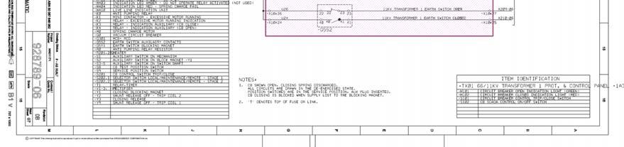
17 Functionality and Isolation Test Example Functionality Test Scenario 1 Functionality Test Scenario 2 Functionality Test Scenario Functionality Test Scenario Functionality Test Scenario 3 Functionality Test Scenario 6 Isolation Test Scenario 1 Functionality Tests Scenario: 1. IN104 sees the correct status of the trip circuit supervision circuit and this status is reflected at the protection relay display and alarm or indication output. 2. In this scenario even though the voltage measured across terminals A25 and A26 correctly reflects the trip circuit supervision status there is no Bluelining of the drawing because the full functionality has not been verified. The operation of the internal relay logic as a scheme must be verified before the input is Bluelined as per Scenario Turning S1 to the TRIP position resulted in opening the circuit breaker. Turning S1 to the CLOSE position resulted in closing the circuit breaker. Note TRIP and CLOSE are both blued in both switch locations on the drawing. 4. S2 set to ON allowed SCADA tripping and closing. S2 set to OFF prevented SCADA tripping and closing. 5. Operating this contact by the local HMI, OCC or a test set had the desired effect of tripping the circuit breaker. Subsequent removal of each link in turn prevented tripping or closing of the circuit breaker. 6. An auto-reclose was successfully initiated when terminal A09 was bridged to terminal A10. OUT105 will not be blued until additional tests have proved that the Auto Reclose Logic correctly operates OUT105. However this does allow the blueing of link X13 and downstream close coil. Isolation Test Scenario: 1. An auto-reclose was successfully initiated, and the subsequent removal of the link prevented an auto-reclose from occurring. Page 15 of 15 Reference MN000301R167 Ver 2
SUBJECT HEADING: Switching Programmes ISSUE: 18
 SUBJECT: Switchgear/Switching PROCEDURE: S04 SUBJECT HEADING: Switching Programmes ISSUE: 18 DATE: Apr 2017 1. INTRODUCTION 1.1 A written programme of switching operations shall be prepared. This programme
Field Instruction Switching Activities. Purpose. Scope. Objective. Safety
 8.22 Switching Activities Purpose This instruction provides a safe system for switching on Horizon Powers Low Voltage, High Voltage and or Transmission electrical apparatus/network, where switching operations
ECP GROUND-MOUNTED SWITCHGEAR WITH PROTECTION RELAYS COMMISSIONING PROCEDURE
 ENGINEERING COMMISSIONING PROCEDURE ECP 11-0512 GROUND-MOUNTED SWITCHGEAR WITH PROTECTION RELAYS COMMISSIONING PROCEDURE Network(s): Summary: EPN, LPN, SPN This procedure details the testing and commissioning
ECP HV METERING EQUIPMENT COMMISSIONING PROCEDURE
 THIS IS AN UNCONTROLLED DOCUMENT, THE READER MUST CONFIRM ITS VALIDITY BEFORE USE Document Number: ECP 11-0515 ENGINEERING COMMISSIONING PROCEDURE ECP 11-0515 HV METERING EQUIPMENT COMMISSIONING PROCEDURE
Table of Contents. Introduction... 1
 Table of Contents Introduction... 1 1 Connection Impact Assessment Initial Review... 2 1.1 Facility Design Overview... 2 1.1.1 Single Line Diagram ( SLD )... 2 1.1.2 Point of Disconnection - Safety...
ECP GROUND-MOUNTED SWITCHGEAR COMMISSIONING PROCEDURE
 Document Number: ECP 11-0511 Network(s): Summary: ENGINEERING COMMISSIONING PROCEDURE ECP 11-0511 GROUND-MOUNTED SWITCHGEAR COMMISSIONING PROCEDURE EPN, LPN, SPN This procedure details the testing and
Draft Kenya Standard for Balloting Not to be Cited as Kenya Standard
 KENYA STANDARD KS 1859-5:2010 ICS 29.240.01 Electrical power transmission and distribution High-voltage operating regulations Part 5: Standard procedure and terminology for the issuing of operating instructions
This section applies to the requirements for the performance of power system studies by both the Design Engineer and the Contractor.
 Basis of Design This section applies to the requirements for the performance of power system studies by both the Design Engineer and the Contractor. Background Information A Short Circuit and Coordination
Section 3. Test Procedures
 Section 3. Information contained within this section shall be read in conjunction with all sections of this manual Non - Compliant Test Results Where acceptable results are not attained in accordance with
C&G Level 3 Award in the Periodic Inspection, Testing and Certification of Electrical Installations
 C&G 2395-01 Level 3 Award in the Periodic Inspection, Testing and Certification of Electrical Installations Phase rotation and verification of voltage drop 1 Outcomes of this Session describe how to assess
One line and Three line diagrams Schematics Wiring Diagrams Logic ladders Ancillary prints Pictorial instructions
 One line and Three line diagrams Schematics Wiring Diagrams Logic ladders Ancillary prints Pictorial instructions One line diagram (1) One line diagrams will typically show in a simple fashion an over
ECP COMPACT AND MICRO SUBSTATION COMMISSIONING PROCEDURE
 Network(s): Summary: ENGINEERING COMMISSIONING PROCEDURE ECP 11-0507 COMPACT AND MICRO SUBSTATION COMMISSIONING PROCEDURE EPN, LPN, SPN This procedure details the testing and commissioning procedures for
University of Central Florida Main Campus. Electric. Service and Meter Installations Requirements. Issued January 26 th, 2017.
 University of Central Florida Main Campus Electric Service and Meter Installations Requirements Issued January 26 th, 2017 1 P a g e Table of Contents 1. GENERAL INFORMATION... 3 2. DEFINITIONS... 3 3.
TABLE OF CONTENT
 Page : 1 of 34 Project Engineering Standard www.klmtechgroup.com KLM Technology #03-12 Block Aronia, Jalan Sri Perkasa 2 Taman Tampoi Utama 81200 Johor Bahru Malaysia TABLE OF CONTENT SCOPE 3 REFERENCES
June Advisory Services on Rewiring Works of Existing Buildings
 June 2014 Welcome Express. to our e-rew Express. In view of the increasing number of rewiring works in recent years, we would like to share with you the advisory services on rewiring works of existing
Title Operating Work - Low Voltage Distribution System. Reference Number POP 06 - (RIC Standard: EP SI)
") Discipline Engineering Standard - NSW Category Electrical Title Operating Work - Low Voltage Distribution System Reference Number POP 06 - (RIC Standard: EP 95 30 00 03 SI) Document Control Status Date
Discipline Engineering Standard - NSW Category Electrical Title Operating Work - Low Voltage Distribution System Reference Number POP 06 - (RIC Standard: EP 95 30 00 03 SI) Document Control Status Date
Section L5: PRE-ENERGIZATION TEST PROCEDURES FOR LOAD-ONLY ENTITIES AND TRANSMISSION-ONLY ENTITIES
 Section L5: PRE-ENERGIZATION TEST PROCEDURES FOR LOAD-ONLY ENTITIES AND TRANSMISSION-ONLY ENTITIES PURPOSE The following is PG&E's procedure for pre-energization inspections. For PG&E to provide the Load
Engineering Diploma Resource Guide ST140 ETP Basic Electricity (Engineering)
") Engineering Diploma Resource Guide ST10 ETP Basic Electricity (Engineering) Introduction Electrical and Electronic technology is a fundamentally important aspect of the engineered world. Whether it s powering
Engineering Diploma Resource Guide ST10 ETP Basic Electricity (Engineering) Introduction Electrical and Electronic technology is a fundamentally important aspect of the engineered world. Whether it s powering
Type Approval JANUARY The electronic pdf version of this document found through is the officially binding version
 STANDARD FOR CERTIFICATION No. 1.2 Type Approval JANUARY 2013 The electronic pdf version of this document found through http://www.dnv.com is the officially binding version The content of this service
 INSTRUCTIONS FOR THE COMMISSIONING AND MAINTENANCE OF DIGITAL GENERATOR PROTECTION 3 I - PRINCIPLES AND APPLICATIONS 4 on 5 6 7 Figure 5 - Inverse time curve (N1) 8 9 1 0 1 1 1 2 1 3 All relays are delivered
TYPE APPROVAL PROCEDURE
 Approval Amendment Record Approval Date Version Description 15/06/2012 1 Initial issue under MTM. Replaces Connex documents cml- 8.13-PR-002 & cml-8.21-po-168 30/11/2012 2 Document revised and updated
Company Directive STANDARD TECHNIQUE: TP14C. Distribution Business Provided Metering Facilities
 Company Directive STANDARD TECHNIQUE: TP14C Distribution Business Provided Metering Facilities Summary This standard technique document details the metering facilities to be provided by the distribution
Shortcomings of the Low impedance Restricted Earth Fault function as applied to an Auto Transformer. Anura Perera, Paul Keller
 Shortcomings of the Low impedance Restricted Earth Fault function as applied to an Auto Transformer Anura Perera, Paul Keller System Operator - Eskom Transmission Introduction During the design phase of
ENGINEERING STANDARD FOR INSTRUMENTS ELECTRICAL POWER SUPPLY AND DISTRIBUTION SYSTEMS FIRST EDITION MAY 2013
 ENGINEERING STANDARD FOR INSTRUMENTS ELECTRICAL POWER SUPPLY AND DISTRIBUTION SYSTEMS FIRST EDITION MAY 2013 This Standard is the property of Iranian Ministry of Petroleum. All rights are reserved to the
Texas Reliability Entity Event Analysis. Event: May 8, 2011 Loss of Multiple Elements Category 1a Event
 Texas Reliability Entity Event Analysis Event: May 8, 2011 Loss of Multiple Elements Category 1a Event Texas Reliability Entity July 2011 Page 1 of 10 Table of Contents Executive Summary... 3 I. Event
Education & Training
 Distribution System Operator Certificate This program provides you with a proficient working knowledge in modern electric power distribution systems. These four classes are designed to walk students through
EE Lecture 14 Wed Feb 8, 2017
 EE 5223 - Lecture 14 Wed Feb 8, 2017 Ongoing List of Topics: URL: http://www.ece.mtu.edu/faculty/bamork/ee5223/index.htm Labs - EE5224 Lab 3 - begins on Tues Feb 14th Term Project - details posted. Limit
Hamdy Faramawy Senior Application Specialist ABB Sweden
 Design, Engineering and Application of New Firm Capacity Control System (FCCS) Mohammed Y. Tageldin, MSc. MIET Senior Protection Systems Engineer ABB United Kingdom mohammed.tageldin@gb.abb.com Hamdy Faramawy
National Grid UK Electricity Transmission plc. NATIONAL SAFETY INSTRUCTION and Guidance
 National Grid UK Electricity Transmission plc NATIONAL SAFETY INSTRUCTION and Guidance NSI 26 RAILWAY CONNECTION CIRCUITS Copyright National Grid plc 2016, all rights reserved. No part of this publication
NSP/007/019 - Guidance on Substation Design: EHV Substation Drawing Policy
 Version:- 1.1 Date of Issue:- Feb 2015 Page 1 of 13 NSP/007/019 - Guidance on Substation Design: EHV Substation Drawing Policy 1. Purpose The purpose of this document is to outline the Northern Powergrid
Series NRX with PXR - Instructions for Neutral Current Sensor Type NF
 Supersedes March 2016 Series NR Series NR with PR - Instructions for Neutral Current Sensor Type NF Instructions apply to: UL1066/ANSI, UL489 series NR NF frame IEC IZM16 WARNING (1) ONLY QUALIFIED ELECTRICAL
2kVA EARTH TESTING CURRENT INJECTION SYSTEM 4046 / 4047 DATASHEET REDPHASE INSTRUMENTS
 2kVA EARTH TESTING CURRENT INJECTION SYSTEM 4046 / 4047 DATASHEET REDPHASE INSTRUMENTS Contents Section Brief Description... 1 Where and why it is used... 1.1 Induced Measureable Parameters... 1.2 Hardware
Notes 1: Introduction to Distribution Systems
 Notes 1: Introduction to Distribution Systems 1.0 Introduction Power systems are comprised of 3 basic electrical subsystems. Generation subsystem Transmission subsystem Distribution subsystem The subtransmission
ELECTRICAL MAINTENANCE SKILLS
 ELECTRICAL MAINTENANCE SKILLS FOR INSTRUMENTATION PERSONNEL COURSE 120: 7 DAYS: Max 8 Candidates The end objectives are identical to those of the Electrical maintenance skills (Course 110) but this starts
Remotes Case 2&3 Form REINDEER Cases 2&3 -Connection Impact Assessment (CIA) Application
 Application") General Application Information Remotes Case 2&3 Form REINDEER Cases 2&3 -Connection Impact Assessment (CIA) Application Hydro One Remote Communities Inc. Lori.Rice@hydroone.com 1-807-474-2828 This Application
General Application Information Remotes Case 2&3 Form REINDEER Cases 2&3 -Connection Impact Assessment (CIA) Application Hydro One Remote Communities Inc. Lori.Rice@hydroone.com 1-807-474-2828 This Application
ENGINEERING. Unit 4 Electrical, electronic engineering operations and application Suite. Cambridge TECHNICALS LEVEL 2
 2016 Suite Cambridge TECHNICALS LEVEL 2 ENGINEERING Unit 4 Electrical, electronic engineering operations and L/615/2134 Guided learning hours: 60 Version 1 September 2016 ocr.org.uk/engineering LEVEL 2
C&G Level 3 Award in the Periodic Inspection, Testing and Certification of Electrical Installations. Earth Fault Loop Impedance Tests
 C&G 2395-01 Level 3 Award in the Periodic Inspection, Testing and Certification of Electrical Installations Earth Fault Loop Impedance Tests 1 Revision Inspections are made to verify that the installed
Guideline for Creating Disconnection Points and Establishing a Not Electrically Connected Area
 Guideline for Creating Disconnection Points and Establishing a Not Document Number: Authorised by: Issue Date: 29 June 2012 Previous Document: 12 February 2010 Principal Authors: J Dohmen Powerlink D Brown
ADDENDUM TO RFQ/P DOCUMENTS PROJECT # ADDENDUM: #01
 ADDENDUM TO RFQ/P DOCUMENTS PROJECT #14-013 ADDENDUM: #01 Solano Community College District SCCD REQUEST FOR QUALIFICATIONS/PROPOSAL Project: HVAC & EMS Efficiency Project Implementation Date: 03/28/2014
DG TRANSFER CONNECTION SCHEME IN ACTIVE DISTRIBUTION NETWORKS
 DG TRANSFER CONNECTION SCHEME IN ACTIVE DISTRIBUTION NETWORKS Abdelrahman AKILA Ahmed HELAL Hussien ELDESOUKI SDEDCO Egypt AASTMT Egypt AASTMT Egypt Abdurrahman.akela@gmail.com ahmedanas@aast.edu hdesouki@aast.edu
SECTION ADMINISTRATIVE REQUIREMENTS SECTION ADMINISTRATIVE REQUIREMENTS
 PART 1 GENERAL 1.01 SECTION INCLUDES A. Project Coordination. B. Preconstruction meeting. C. Progress meetings. D. Preinstallation conferences. E. Requests for information (RFI). F. Coordination drawings.
ECP DISTRIBUTION TRANSFORMER COMMISSIONING PROCEDURE
 Document Number: ECP 11-0506 ENGINEERING COMMISSIONING PROCEDURE ECP 11-0506 DISTRIBUTION TRANSFORMER COMMISSIONING PROCEDURE Network(s): Summary: EPN, LPN, SPN This procedure details the testing and commissioning
E N G I N E E R I N G M A N U A L
 1 1 1.0 PURPOSE The purpose of this document is to define policy and provide engineering guidelines for the AP operating companies (Monongahela Power Company, The Potomac Edison Company, and West Penn
Generation Interconnection Requirements at Voltages 34.5 kv and Below
 Generation Interconnection Requirements at Voltages 34.5 kv and Below 2005 March GENERATION INTERCONNECTION REQUIREMENTS AT 34.5 KV AND BELOW PAGE 1 OF 36 TABLE OF CONTENTS 1. INTRODUCTION 5 1.1. Intent
SECTION LOW VOLTAGE ACTIVE HARMONIC FILTER SYSTEM NEMA 1 ENCLOSED
 SECTION 16280 LOW VOLTAGE ACTIVE HARMONIC FILTER SYSTEM NEMA 1 ENCLOSED PART 1 - GENERAL 1.1 SUMMARY This specification defines the requirements for active harmonic filter systems in order to meet IEEE-519-2014
SECTION SUBMITTAL PROCEDURES PART 1 - GENERAL 1.1 RELATED DOCUMENTS
 SECTION 01 33 00 - SUBMITTAL PROCEDURES PART 1 - GENERAL 1.1 RELATED DOCUMENTS A. Drawings and general provisions of the Contract, including General and Supplementary Conditions and other Division 01 Specification
PROTECTION of electricity distribution networks
 PROTECTION of electricity distribution networks Juan M. Gers and Edward J. Holmes The Institution of Electrical Engineers Contents Preface and acknowledgments x 1 Introduction 1 1.1 Basic principles of
PJM Manual 07:: PJM Protection Standards Revision: 2 Effective Date: July 1, 2016
 PJM Manual 07:: PJM Protection Standards Revision: 2 Effective Date: July 1, 2016 Prepared by System Planning Division Transmission Planning Department PJM 2016 Table of Contents Table of Contents Approval...6
2394 EXAM PAPER. 1. State THREE circumstances that would require a periodic inspection and test to be carried out on an installation
 2394 EXAM PAPER 1. State THREE circumstances that would require a periodic inspection and test to be carried out on an installation 2. There are various documents that are relevant to the Inspection and
Appendix S: PROTECTION ALTERNATIVES FOR VARIOUS GENERATOR CONFIGURATIONS
 Appendix S: PROTECTION ALTERNATIVES FOR VARIOUS GENERATOR CONFIGURATIONS S1. Standard Interconnection Methods with Typical Circuit Configuration for Single or Multiple Units Note: The protection requirements
Utility Interconnection and System Protection
 Utility Interconnection and System Protection Alex Steselboim President, Advanced Power Technologies, Inc. Utility paralleling vs. isolated operation. Isochronous kw load sharing Reactive power (VAR) sharing
Licensed Electricians Practical Assessment (LEP)
") Licensed Electricians Practical Assessment (LEP) Surname: Given Names: Date: Time: Location: Assessment Time (includes reading and preparation time): At the end of this time you will be asked to stop.
Licensed Electricians Practical Assessment (LEP) Surname: Given Names: Date: Time: Location: Assessment Time (includes reading and preparation time): At the end of this time you will be asked to stop.
EDS LV ELECTRICAL SERVICE DRAWINGS
 Document Number: EDS 08-2110 Network(s): Summary: ENGINEERING DESIGN STANDARD EDS 08-2110 LV ELECTRICAL SERVICE DRAWINGS EPN, LPN, SPN This standard details the drawings for service positions and connection
ELECTRICAL NETWORKS SPECIFICATION TECHNICAL SPECIFICATION FOR A 230V/110V AND 400V/110V TRANSFORMER
 Approval Amendment Record Approval Date Version Description 03/05/2017 1 Initial issue PRINTOUT MAY NOT BE UP-TO-DATE; REFER TO METRO INTRANET FOR THE LATEST VERSION Page 1 of 13 Table of Contents 1. Purpose...
DESIGN PRACTICE NOTE DESIGN/REVIEW REQUIREMENTS FOR TRACTION BONDING PLAN
 Approval Amendment Record Approval Date Version Description 01/04/2014 1 Initial Issue under MTM PRINTOUT MAY NOT BE UP-TO-DATE; REFER TO METRO INTRANET FOR THE LATEST VERSION Page 1 of 7 Table of Contents
NEO TELE-TRONIX PVT. LTD. 6/7 Bijoygarh, Kolkata , Tel : ; Fax :
 NEO TELE-TRONIX PVT. LTD. 6/7 Bijoygarh, Kolkata - 700 032, Tel : 033 2477 3126; Fax : 033 2477 2403 www.ntplindia.com SPECIFICATION NTPL MAKE MICRO-CONTROLLER BASED AUTOMATIC 50KV/10A AC HIGH VOLTAGE
Licensed Electricians Practical Assessment (LEP)
") Licensed Electricians Practical Assessment (LEP) Surname: Date: Given Names: Time: Assessment Time (includes 10 minutes reading time): At the end of this time you will be asked to stop. 4 hours Have you
Licensed Electricians Practical Assessment (LEP) Surname: Date: Given Names: Time: Assessment Time (includes 10 minutes reading time): At the end of this time you will be asked to stop. 4 hours Have you
ECP HV INSULATION TESTING
 Document Number: ECP 11-0006 Network(s): Summary: ENGINEERING COMMISSIONING PROCEDURE EPN, LPN, SPN ECP 11-0006 HV INSULATION TESTING This standard details the policy for the on-site insulation testing
Company Directive STANDARD TECHNIQUE: SD1E/2. Technical Requirements for Customer Export Limiting Schemes
 Company Directive STANDARD TECHNIQUE: SD1E/2 Technical Requirements for Customer Export Limiting Schemes Policy Summary This Standard Technique specifies the requirements for customer owned Export Limitation
SWITCHING SAFETY & RELIABILITY CONFERENCE
 SWITCHING SAFETY & RELIABILITY CONFERENCE JARGON WORKSHEET Energize (v) Energize is the process of applying rated voltage to circuit or equipment. Modified IEEE or OSHA from Adj. to verb. To make a piece
Module Title: Electrical Installation II Laboratory Sheet:
 Vocational Training Council Hong Kong Institute of Vocational Education Department of Engineering Module Title: Electrical Installation II Laboratory Sheet: Student name: Course / Year: Subject: Date:
DP&L s Technical Requirements for Interconnection and Parallel Operation of Distributed Generation
 DP&L s Technical Requirements for Interconnection and Parallel Operation of Distributed Generation Technical Requirements for Interconnection and Parallel Operation of Distributed Generation Single Phase
Wind Power Facility Technical Requirements CHANGE HISTORY
 CHANGE HISTORY DATE VERSION DETAIL CHANGED BY November 15, 2004 Page 2 of 24 TABLE OF CONTENTS LIST OF TABLES...5 LIST OF FIGURES...5 1.0 INTRODUCTION...6 1.1 Purpose of the Wind Power Facility Technical
FINAL - ER 70 Electrician Regulations Answer Schedule. Question 1 Marks Reference Marking notes
 FINAL - ER 70 Electrician Regulations Answer Schedule Notes:1. (1 mark) means that the preceding statement/answer earns 1 mark. 2. This schedule sets out the expected answers to the examination questions.
Load-Trainer Transformer Simulator
 Load-Trainer Transformer Simulator XFMR-4BUSHING Four Bushing Transformer Simulator Operation Manual Product Description 2 Components Set-Up 3 4 Simulator Description 4 Front Panel Description 5 Toggle
Southern Company Interconnection Requirements for Inverter-Based Generation
 Southern Company Interconnection Requirements for Inverter-Based Generation September 19, 2016 Page 1 of 16 All inverter-based generation connected to Southern Companies transmission system (Point of Interconnection
Back to the Basics Current Transformer (CT) Testing
 Testing") Back to the Basics Current Transformer (CT) Testing As test equipment becomes more sophisticated with better features and accuracy, we risk turning our field personnel into test set operators instead of
Back to the Basics Current Transformer (CT) Testing As test equipment becomes more sophisticated with better features and accuracy, we risk turning our field personnel into test set operators instead of
FAQ ON EARTHING STANDARDS 16/08/2018
 FAQ ON EARTHING STANDARDS 16/08/2018 This document has been updated to include changes made to substation earthing layouts that have been made necessary due to copper theft. The main changes to be aware
ADDENDUM NO. 3 PROJECT: COURTLAND PUMP STATION CONTRACT: IFB NO COM.00030
 ADDENDUM NO. 3 PROJECT: COURTLAND PUMP STATION CONTRACT: IFB NO. 2018-008-COM.00030 To: Prospective Bidders of Record Date: January 8, 2019 The following changes, additions, revisions, and/or deletions
EE Lecture 15 (recorded Feb 9, 2011) Fri Feb 15, 2013
 Fri Feb 15, 2013") EE 5223 - Lecture 15 (recorded Feb 9, 2011) Fri Feb 15, 2013 Ongoing List of Topics: URL: http://www.ece.mtu.edu/faculty/bamork/ee5223/index.htm Term Project - structuring, details Exercises posted Today:
EE 5223 - Lecture 15 (recorded Feb 9, 2011) Fri Feb 15, 2013 Ongoing List of Topics: URL: http://www.ece.mtu.edu/faculty/bamork/ee5223/index.htm Term Project - structuring, details Exercises posted Today:
ECP HV INSULATION TESTING
 Document Number: ECP 11-0006 Network(s): Summary: All ENGINEERING COMMISSIONING PROCEDURE ECP 11-0006 HV INSULATION TESTING This standard details the policy for the on-site insulation testing of new and
PLAN... RESPOND... RESTORE! Utility Automation & Information Technology... Automation Rising
 Automation Rising Q U A R T E R LY First Quarter 2013 The Digital Magazine of Automation & Information Technology for Electric, Gas and Water Utilities Utility Automation & Information Technology... PLAN...
Load-Trainer Transformer Simulator
 Load-Trainer Transformer Simulator XFMR-3BUSHING Three Bushing Transformer Simulator Operation Manual C-00879 XFMR-3BUSHING (11-11-15) Product Description 2 Components 3 Set-Up 4 Simulator Description
Portable Appliance Testers. OmegaPAT MI 2140 BetaPAT MI 2141 User Manual Ver Code No
 Portable Appliance Testers OmegaPAT MI 2140 BetaPAT MI 2141 User Manual Ver. 1.2. Code No. 20 750 684 Distributor: Producer: METREL d.d. Ljubljanska 77 SI-1354 Horjul E-mail: metrel@metrel.si http://www.metrel.si
JEFFERSON LAB TECHNICAL ENGINEERING & DEVELOPMENT FACILITY (TEDF ONE) Newport News, Virginia
 Newport News, Virginia") BULLETIN NO. 6 TO THE PLANS AND SPECIFICATIONS FOR JEFFERSON LAB TECHNICAL ENGINEERING & DEVELOPMENT FACILITY (TEDF ONE) Newport News, Virginia EwingCole Architects.Engineers.Interior Designers.Planners
BULLETIN NO. 6 TO THE PLANS AND SPECIFICATIONS FOR JEFFERSON LAB TECHNICAL ENGINEERING & DEVELOPMENT FACILITY (TEDF ONE) Newport News, Virginia EwingCole Architects.Engineers.Interior Designers.Planners
RELEVANT ELECTRICAL STANDARDS
 RELEVANT ELECTRICAL STANDARDS Issue 2 February 2014 National Grid 2014 No part of this publication may be reproduced, stored in a retrieval system, or transmitted in any form or by any means electronic,
Survey of Operational Events
 Survey of Operational Events Final presentation,, Stockholm Mikael Wämundson 1 Content Background to the study Conclusions from literature survey Notable events at Nordic NPPs Mitigating actions taken
Relay Communication Misoperations. Southwest Power Pool System Protection and Control Working Group
 Relay Communication Misoperations Southwest Power Pool System Protection and Control Working Group Relay Misoperations The fundamental objective of power system protection schemes is to quickly provide
Using a Multiple Analog Input Distance Relay as a DFR
 Using a Multiple Analog Input Distance Relay as a DFR Dennis Denison Senior Transmission Specialist Entergy Rich Hunt, M.S., P.E. Senior Field Application Engineer NxtPhase T&D Corporation Presented at
SECTION CLOSEOUT SUBMITTALS SECTION CLOSEOUT SUBMITTALS
 PART 1 GENERAL 1.01 SECTION INCLUDES A. Project Record Documents. B. Operation and Maintenance Manuals. C. Warranties and bonds. 1.02 RELATED REQUIREMENTS SECTION 01 78 00 A. Section 01 30 00 - Administrative
SYNCHRONISING AND VOLTAGE SELECTION
 SYNCHRONISING AND VOLTAGE SELECTION This document is for Relevant Electrical Standards document only. Disclaimer NGG and NGET or their agents, servants or contractors do not accept any liability for any
Capstone Turbine Corporation Nordhoff Street Chatsworth CA USA Phone: (818) Fax: (818) Web:
 Fax: (818) Web:") Phone: (818) 734-5300 Fax: (818) 734-5320 Web: www.capstoneturbine.com Technical Reference Capstone MicroTurbine Electrical Installation 410009 Rev F (October 2013) Page 1 of 31 Capstone Turbine Corporation
Phone: (818) 734-5300 Fax: (818) 734-5320 Web: www.capstoneturbine.com Technical Reference Capstone MicroTurbine Electrical Installation 410009 Rev F (October 2013) Page 1 of 31 Capstone Turbine Corporation
SPECIFICATION FOR HORIZONTAL AIRFLOW OUTDOOR RESISTIVE LOAD BANK
 SPECIFICATION FOR HORIZONTAL AIRFLOW OUTDOOR RESISTIVE LOAD BANK PART 1.0 GENERAL 1.1 SCOPE A. This specification contains the minimum requirements for the design, manufacture and testing of a UL listed,
Section Meetings Section Material and Equipment. None Required
 January 2000 Page 1 of 8 PART 1 GENERAL 1.01 OTHER CONTRACT DOCUMENTS 1.02 DESCRIPTION OF WORK 1.03 RELATED WORK PART 2 PRODUCTS The General Conditions of the Contract, General Requirements and Supplemental
Application and Commissioning Manual for Numerical Over & Under Voltage Protection Relays Type MVT181 CONTENTS PAGE APPLICATION 2-7 INSTALLATION 8-16
 Application and Commissioning Manual for Numerical Over & Under Voltage Protection Relays Type MVT181 CONTENTS PAGE APPLICATION 2-7 INSTALLATION 8-16 COMMISSIONING 17-22 WIRING DIAGRAM 23 1. INTRODUCTION
How to maximize reliability using an alternative distribution system for critical loads
 White Paper WP024001EN How to maximize reliability using an alternative distribution system for critical loads Executive summary The electric power industry has several different distribution topologies
Absolute Block. Uncontrolled When Printed Document to be part superseded by GKRT0055 Iss 1 and GKRT0077 Iss 1 (published on 07/09/2013)
") Signatures removed from electronic version Submitted by... Richard Genner Nominated Responsible Manager Approved by... Philip Wiltshire Chairman, Train Control & Communications Subject Committee Approved
Signatures removed from electronic version Submitted by... Richard Genner Nominated Responsible Manager Approved by... Philip Wiltshire Chairman, Train Control & Communications Subject Committee Approved
Status Date Prepared Reviewed Endorsed Approved
 Discipline Engineering Standard NSW Category Signalling Title Reference Number SDS 17 (RIC Standard: SC 00 13 01 17 SP) Document Control Status Date Prepared Reviewed Endorsed Approved Mar 05 Standards
Substation Testing and Commissioning: Power Transformer Through Fault Test
 1 Substation Testing and Commissioning: Power Transformer Through Fault Test M. Talebi, Member, IEEE, Power Grid Engineering Y. Unludag Electric Power System Abstract This paper reviews the advantage of
Software Services, Section 16748, Add as an attachment to this section Attachment A enclosed with this addendum.
 This addendum is hereby made part of the Request for Bid for the above-named project and shall be taken into consideration by all firms preparing a submittal on this project. Acknowledge receipt of this
Busbars and lines are important elements
 CHAPTER CHAPTER 23 Protection of Busbars and Lines 23.1 Busbar Protection 23.2 Protection of Lines 23.3 Time-Graded Overcurrent Protection 23.4 Differential Pilot-Wire Protection 23.5 Distance Protection
Les Hampson Cert Ed FSCTE, Chairman CAI Technical Committee
 Making the Bond Les Hampson Cert Ed FSCTE, Chairman CAI Technical Committee After many man hours of deliberation and consultation the Code of Practice Electrical Safety Requirements for Signal Reception
Section 16621A - AUTOMATIC TRANSFER SWITCH. Part 1 General
 Section 16621A - AUTOMATIC TRANSFER SWITCH Part 1 General 1.01 One 600 Amp, 3 Phase, 480 Volt Automatic Transfer Switch (ATS) shall be provided with gasketed enclosure. The ATS shall consist of an inherently
ELECTRICIAN S THEORY EXAMINATION 17 November 2012 QUESTION AND ANSWER BOOKLET
 Candidate Code No. ET43 For Board Use Only Result Date Int Result Date Int ELECTRICIAN S THEORY EXAMINATION 17 November 2012 QUESTION AND ANSWER BOOKLET INSTRUCTIONS READ CAREFULLY Time Allowed: Three
STATE OF OHIO DEPARTMENT OF TRANSPORTATION SUPPLEMENTAL SPECIFICATION 919 RAILROAD PREEMPTION INTERFACE. January 15, 2016
 STATE OF OHIO DEPARTMENT OF TRANSPORTATION SUPPLEMENTAL SPECIFICATION 919 RAILROAD PREEMPTION INTERFACE January 15, 2016 919.01 Traffic Signal Cabinet and Controller Unit General Requirements 919.02 Approved
EDS FAULT LEVELS
 Document Number: EDS 08-1110 Network(s): Summary: EPN, LPN, SPN ENGINEERING DESIGN STANDARD EDS 08-1110 FAULT LEVELS This standard provides guidance on the calculation, application and availability of
Testing for ground faults on storage batteries. Megger is a registered trademark
 WWW.MEGGER.COM Testing for ground faults on storage batteries Megger is a registered trademark Title Author Andrew Sagl Date January 2010 Keywords Abstract E-mail BGFT, circuit breaker uninterruptable
MESP TECHNICAL SPECIFICATION FOR AN ESSENTIAL SERVICES SUPPLY STEP UP TRANSFORMER
 Engineering Specification TECHNICAL SPECIFICATION FOR AN ESSENTIAL Version: 3 Issued: 14 October 2016 Owner: Chief Engineer Approved By: Andrew Russack Head of Engineering - Electrical PRINTOUT MAY NOT
Substation Preventive Maintenance
 Substation Preventive Maintenance PROVINCIAL ELECTRICITY AUTHORITY 1 Presentation Contents 1) A kind of substation 2) Electrical equipment details of AIS substation 3) Electrical equipment details of GIS
VI 3 - i TABLE OF CONTENTS
 VI 3 - i TABLE OF CONTENTS 3 PROJECT SPECIFIC DATA... 1 3.1 DEFINITIONS... 1 3.1.1 Design Data, High and Medium Voltage... 1 3.1.2 Design Data, Low Voltage Equipment... 2 3.1.3 Phase Relationship... 3