CADD Guidelines Manual
|
|
|
- Osborn Patterson
- 6 years ago
- Views:
Transcription
1 CADD Guidelines Manual 2575 Enterprise Road Clearwater, FL Phone: Fax: Effective OCTOBER 06, 2010 Revised S:\STANDARDS\CADD_Guidelines\CADD_Guidelines_Manual.doc 1
2 TABLE OF CONTENTS SECTION 1 - INTRODUCTION 1.1 PURPOSE 1.2 SCOPE 1.3 DISTRIBUTION 1.4 PROCEDURE FOR REVISIONS AND UPDATES SECTION 2 - TAMPA BAY WATER CADD SOFTWARE 2.1 GENERAL 2.2 PROCUREMENT OF ENGINEERING/CADD HARDWARE AND SOFTWARE 2.3 SOFTWARE PROGRAMS 2.4 PRODUCT SUPPORT 2.5 TRANSLATION OF FILES SECTION 3 - AUTOCAD RESOURCE AND SUPPORT FILES 3.1 GENERAL 3.2 DRAWING TEMPLATE 3.3 TEXT STYLE 3.4 FONT Document and Figure Sheet Fonts Engineering Sheet Fonts 3.5 TEXT SIZES Cover Sheet Title Block Detail Sheet Figures 3.6 LINETYPES 3.7 PLOT STYLE & LINE WEIGHTS Color Table Selection 3.8 PRINTER DRIVERS SECTION 4 - PROJECT DIRECTORY STRUCTURE 4.1 GENERAL 4.2 DATA DIRECTORY STRUCTURE Project Data Directory Structure S:\STANDARDS\CADD_Guidelines\CADD_Guidelines_Manual.doc 2
3 4.3.2 Finalize Data Directory Structure 4.3 CADD DRAWING FILE NAMES Professional Codes Drawing Codes SECTION 5 - FILE LAYER STANDARDS 5.1 GENERAL 5.2 LAYER NAMING SECTION 6 - DELIVERY PROCEDURE 6.1 GENERAL 6.2 PROJECT DOCUMENTS DELIVERED AUTOCAD ENGINEERING DRAWINGS RETURNED ENGINEERING DRAWINGS SECTION 7 - DEFINITION & FILE FORMATS 7.1 DEFINITIONS 7.2 FILE FORMATS 7.3 AUTOCAD FILE FORMATS 7.4 MICROSTATION FORMATS SECTION 8 - TEMPLATES 8.1 COVER SHEET 8.2 TITLE BLOCK 8.3 DETAIL SHEET DETAIL SHEET DETAIL SHEET DETAIL SHEET DETAIL SHEET DETAIL SHEET DETAIL SHEET 7 S:\STANDARDS\CADD_Guidelines\CADD_Guidelines_Manual.doc 3
4 SECTION 1 - INTRODUCTION Computer-Aided Design and Drafting Manual 1.1 PURPOSE Tampa Bay Water is a special district created by an interlocal agreement to supply wholesale water year round to its member of governments, who in turn provide water to people in the tri-county area. It is Tampa Bay Water s and its member of government s responsibility for planning and development of Tampa Bay Water s infrastructure for future growth of the service area. This manual sets forth standards and procedures to be used for all technical and engineering drawings, or Computer-Aided Design & Drafting (CADD) files and drawings, and related work performed for Tampa Bay Water. These standards must be followed to ensure a quality product. Many individuals from different departments reference these guidelines to support their needs. All Computer-Aided Design (CAD) services shall be performed under the supervision of a Florida licensed Professional Engineer, Architect or Surveyor whose responsibilities shall include seeing that all services are in compliance with the current Florida State Statues. The CADD Guidelines create a balanced intergraded system establishing minimum requirements that must be met for Tampa Bay Water CADD projects, to protect the safety and general welfare to the people of the service area. While the Tampa Bay Water CADD Guidelines provide a standard for all CADD projects, situations will occur where these guidelines can NOT apply. If variances from the CADD Guidelines are required to a project, the variables must be approved in writing by the Tampa Bay Water Project Manager and documented. 1.2 SCOPE The CADD Guidelines Manual is to be used by all in-house personnel producing engineering projects. It is to be included in all contracts requiring engineering plans preparation. This manual will affect Tampa Bay Water and all consultants, contractors and others who utilize engineering CADD applications, or engineering data produced by these applications. S:\STANDARDS\CADD_Guidelines\CADD_Guidelines_Manual.doc 4
5 1.3 DISTRIBUTION The CADD Guidelines Manual is distributed in electronic form and may be downloaded from the following website: PROCEDURES FOR REVISIONS AND UPDATES Users of the CADD Guidelines are encouraged to send comments and suggestions for changes or improvements to: The comments and suggestions will be reviewed by staff before approval, with a revision number and date. After approval, all updates shall be posted at the link above with the revision number and date.. S:\STANDARDS\CADD_Guidelines\CADD_Guidelines_Manual.doc 5
6 SECTION 2 - SYSTEM REQUIREMENTS 2.1 GENERAL This section establishes the minimum requirements for procurement, maintenance, and technical support of Tampa Bay Water s Engineering/CADD hardware and software systems. The Tampa Bay Water CADD software is updated on a bi-yearly basis, and distributed to the proper computers and users. 2.2 PROCUREMENT OF ENGINEERING/CADD HARDWARE AND SOFTWARE The CADD Users and IT personnel will annually evaluate the needs for computer hardware, and to provide recommendations for procurement of any CADD hardware where appropriate, to insure consistency with current technology. The IT department will begin an evaluation of hardware to be procured for use in CADD. 2.3 SOFTWARE PROGRAMS There are multiple software programs used by Tampa Bay Water; AutoCAD, MicroStation, Bentley View, and Design Review. AutoCAD and MicroStation are commercial programs that Tampa Bay Water has purchased a license(s) to be used. Tampa Bay Water is not responsible for the use of any software used by a consultant or any other agency, company, or member of government. 2.4 PRODUCT SUPPORT Currently, Windows operating system, AutoCAD version 2010 is the required software. Other software (MicroStation V8) can be used, but is not accepted as a final deliverable for Tampa Bay Water projects. Staff from the IS Support department maintains all CADD software licenses, updates to the CADD server, and installations of the software. If support is needed, contact IS Support Department. 2.5 TRANSLATION OF FILES Tampa Bay Water requires AutoCAD version 2010 format for the delivery of all CADD design files except when specified by the Project Manager. The data producer is solely responsible for any translation required to convert non-autocad files to the AutoCAD design format (dwg). All translated design files shall conform to the file naming convention and symbology standards adopted by Tampa Bay Water for electronic plans as specified herein and mandated by the CADD Guidelines Manual. Specifically, MicroStation conversions to AutoCAD shall maintain the Layer Name structures, line weights and widths, X-references, Blocks and legible text. It is the responsibility of the data producer to ensure correct translation of the design files, including adherence to the specifications contained herein and the validity of the geometric elements. S:\STANDARDS\CADD_Guidelines\CADD_Guidelines_Manual.doc 6
7 SECTION 3 - AUTOCAD RESOURCE AND SUPPORT FILES 3.1 GENERAL Tampa Bay Water requires a uniform or balanced project layout of fonts, text styles, symbols, linetypes, colors, line weight, title blocks, detail sheets, and plots. The resource and support file standards herein are a minimum requirement that shall be followed for all Tampa Bay Water CADD projects, but are subject to change. Variances shall occur due to project requirements, but must be signed and approved in writing by the Project Manager. 3.2 DRAWING TEMPLATE A standard drawing template is necessary to maintain project consistency. The Tampa Bay Water drawing template contains the standard fonts, line types, colors, layers, and printer drivers associated with the agency. The template must maintain the model space projection set to NGVD29 vertical datum and NAD 83 horizontal datum State Plane Florida West FIPS U.S. Feet. To be used with ESRI (ArcGIS). Drawings with relative spatial units will NOT be accepted. *A zip file shall be delivered to the awarded project Consultant, Contractor, and/or Sub-Contractor consisting of Tampa Bay Water s standard electronic CADD files. See Figure 12 S:\STANDARDS\CADD_Guidelines\CADD_Guidelines_Manual.doc 7
8 Figure TEXT STYLE In AutoCAD there are two different types of text, single-line and multiline text. Single-line text shall be used for simple entries, single line labeling, leader lines, and vertical text and not used for notes, tables, paragraphs, and labels & leader lines with multiple lines. Multiline text shall be used for long and complex entries, notes, tables, paragraphs, and labels and leader lines with multiple lines to maintain proper alignment, justification, and spacing. See Figure FONT There are many different prefaces of font types in addition to the different types of fonts, TrueType fonts, SHX fonts, Adobe fonts, Mac and PC Postscript fonts, and cross platform fonts. All these prefaces contain many groups of fonts. The font may be book, regular, heavy, bold, light, italic, bold italic, and underlined. For example Futura: Futura Bk BT, Futura HV BT, Futura LT BT, Futura LTCn Bt, and Futura XBlkCnIt BT Document and Figure Sheet Fonts Tampa Bay Water s standard fonts are Garamond and Futura. For examples of spacing, size, layouts, and uses of documents that are not engineering drawings, refer to the Tampa Bay Water Identity Manual Engineering Sheet Fonts Tampa Bay Water requires Garamond to be used in the title blocks, detail titles, and project titles; Futura to be used for notes, labels, and dimensions. See Figures 1 and 2 S:\STANDARDS\CADD_Guidelines\CADD_Guidelines_Manual.doc 8
9 Figure 1 S:\STANDARDS\CADD_Guidelines\CADD_Guidelines_Manual.doc 9
10 Figure 2 S:\STANDARDS\CADD_Guidelines\CADD_Guidelines_Manual.doc 10
11 3.5 TEXT SIZES All CADD projects are required to have the correct size text for the scale of the design or drawing. The size of the text makes one text a higher focal point then another to represent a priority, or a different group. The Tampa Bay Water CADD Guidelines must be followed to maintain a uniform project and design. The correct text size of each drawing template shown below and in the Appendix is properly scaled in each AutoCAD or electronic file. See Figures 3 through Cover Sheet Figure 3 S:\STANDARDS\CADD_Guidelines\CADD_Guidelines_Manual.doc 11
12 3.5.2 Title Block Figure 4 S:\STANDARDS\CADD_Guidelines\CADD_Guidelines_Manual.doc 12
13 3.5.3 Detail Sheet Figure 5 S:\STANDARDS\CADD_Guidelines\CADD_Guidelines_Manual.doc 13
14 3.5.4 Figure Sheet Figure 6 S:\STANDARDS\CADD_Guidelines\CADD_Guidelines_Manual.doc 14
15 3.6 LINETYPES A linetype is a repeating pattern of dashes, dots, and blank spaces displayed in a line or curve, used to distinguish the difference between elements in a drawing. For example different linetypes display graphical difference between a boundary line and power line by the different repeating design but they can be the same color. See Figure 7 thru 8. S:\STANDARDS\CADD_Guidelines\CADD_Guidelines_Manual.doc 15
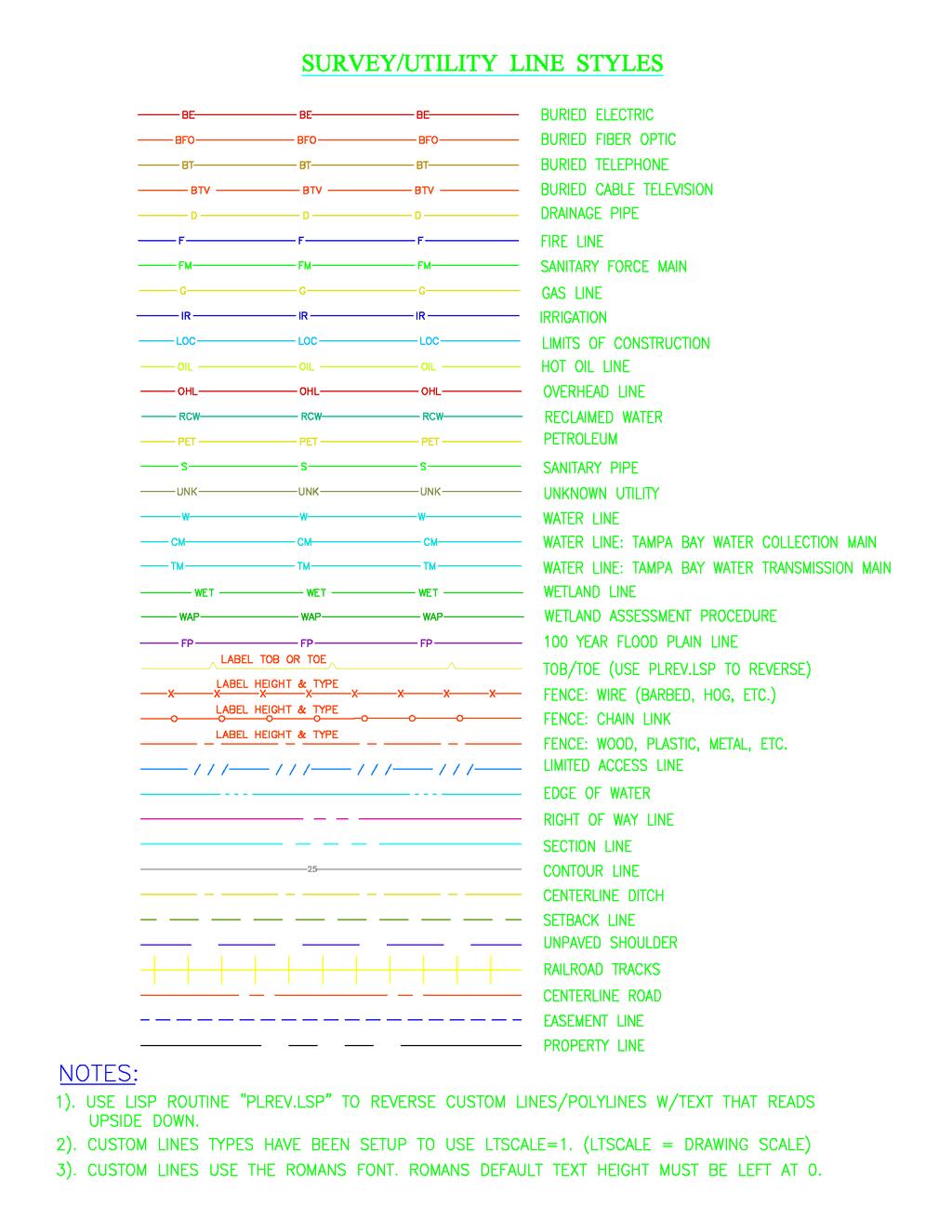
16 Figure 7 S:\STANDARDS\CADD_Guidelines\CADD_Guidelines_Manual.doc 16
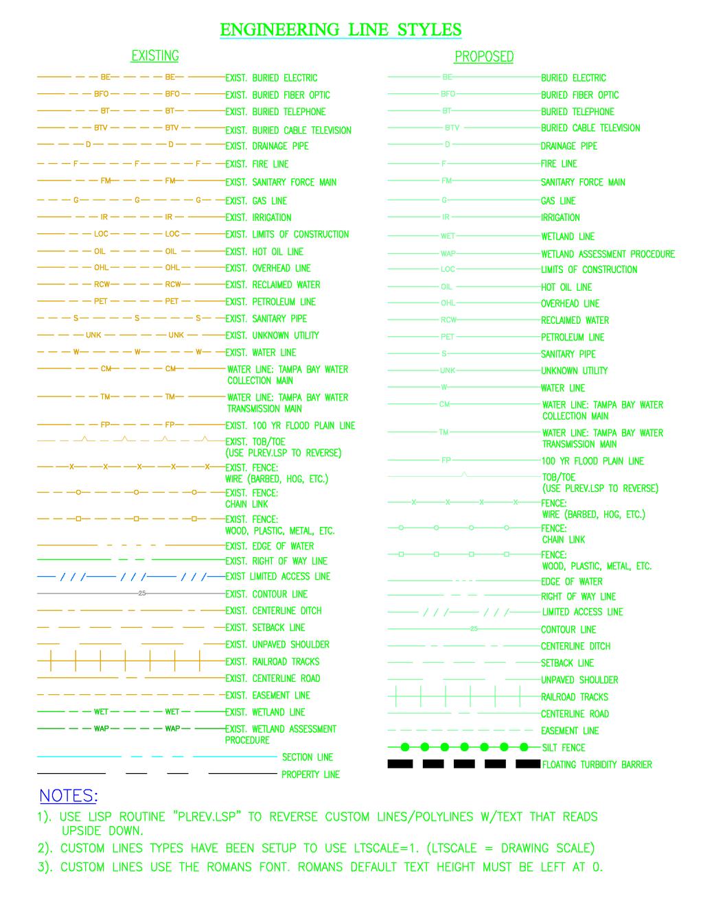
17 Figure 8 S:\STANDARDS\CADD_Guidelines\CADD_Guidelines_Manual.doc 17

18 3.7 PLOT STYLE & LINE WEIGHTS A standard plot style is necessary to allow users to visually identify elements with ease in shared files and for consistency in color plotting. The AutoCAD plot style or color table defines 256 colors from which an active color can be selected and applied to an element. The most important aspect for the standardization of colors is the number that is applied. The plot style defined by Tampa Bay Water is a selection of colors to be used for specific objects, lines, text, and dimensions. The different colors make the layers of a drawing more apparent and easier to share, review, and modify for future use BLACK & WHITE TABLE SELECTION Listed below, See Figure 9 is the Tampa Bay Water black and white table (tbw2009-bw.ctb) that is required to be used herein, for all CADD projects, unless written approval is authorized by the Project Manager. Figure 9 S:\STANDARDS\CADD_Guidelines\CADD_Guidelines_Manual.doc 18
19 3.8 PRINTER DRIVERS The printer drivers included in the required drawing templates contain the proper scale, dimensions, colors, and line weights for each Tampa Bay Water printer. For examples, the HP Designjet 4500ps is a large document plotter designated to print engineering drawings 34 x 44, 22 x 34, and other custom sizes larger than 11 x 17, with the maximum size of 42 width and length of the paper roll (approximately 300 feet.) Another printer is the HP Laserjet 5500 color printer designated to print reduced size engineering drawings and figure sheets 11 x 17, 8.5 x 14, and 8.5 x 11. To view a list of available printers and a list of plot drivers. See Figure 10 Printer Name Print Sizes Description HP Color LaserJet x11, 8.5x14, 11x17 A color laser printer (raster image compatible) HP Color LaserJet x11, 8.5x14, 11x17 A color laser printer (raster image compatible) HP Designjet 2500cp 11x17and larger, Max 36"x Roll A color plotter 36" x 100' roll (raster image compatible) HP Designjet 4500ps 11x17and larger, Max 42"x Roll A color plotter 42" x 300' roll (raster image compatible) HP LaserJet x11, 8.5x14, 11x17 A black and white laser printer (raster image compatible) HP LaserJet 2300d 8.5x11, 8.5x14, 11x17 A black and white laser printer (raster image compatible) HP LaserJet x11, 8.5x14, 11x17 A black and white laser printer (raster image compatible) HP LaserJet x11, 8.5x14, 11x17 A black and white laser printer (raster image compatible) HP LaserJet x11, 8.5x14, 11x17 A black and white laser printer (raster image compatible) HP LaserJet 4100 tn 8.5x11, 8.5x14, 11x17 A black and white laser printer (raster image compatible) HP LaserJet 4250 dtn 8.5x11, 8.5x14, 11x17 A black and white laser printer (raster image compatible) HP Photosmart x7, 8.5x11, 8.5x14, 11x17 A color photo printer able to print without margins (raster image compatible) Lanier 5222 Copier 8.5x11, 8.5x14, 11x17 A black and white laser printer, scanner, and copier (raster image compatible) Lanier x11, 8.5x14, 11x17 A black and white laser printer, scanner, and copier (raster image compatible) Lanier 5635 Copier 8.5x11, 8.5x14, 11x17 A black and white laser printer, scanner, and copier (raster image compatible) Lanier x11, 8.5x14, 11x17 A black and white laser printer, scanner, and copier (raster image compatible) Lanier LD x11, 8.5x14, 11x17 A black and white laser printer, scanner, and copier (raster image compatible) Lanier LD x11, 8.5x14, 11x17 A black and white laser printer, scanner, and copier (raster image compatible) Lanier LP138c 8.5x11, 8.5x14, 11x17 A color laser printer, scanner, and copier (raster image compatible) Lexmark Optra T x11, 8.5x14, 11x17 A black and white laser printer (raster image compatible) Lexmark Optra T x11, 8.5x14, 11x17 A black and white laser printer (raster image compatible) Ricoh MP x11, 8.5x14, 11x17 A black and white laser printer, scanner, and copier (raster image compatible) Figure 10 S:\STANDARDS\CADD_Guidelines\CADD_Guidelines_Manual.doc 19
20 SECTION 4 - DIRECTORY STRUCTURE 4.1 GENERAL Many projects are designed, built, and referenced over a long period of time and must stay organized. To maintain organization, each project must have its own project number and name placed in a directory system with files and folders. Projects may have the same or similar names, causing confusion and poor management. To resolve this issue a unique alphanumeric character system assigned to each file was created and must be followed. 4.2 DATA DIRECTORY STRUCTURE The engineering drawing files shall be organized and maintained in a standard file directory structure. The file folder shall be spelled without any spaces, requiring the use of underline spaces and/or dashes between numbers, words, and names. The reason for no spacing is due to programs creating %% for every space between a character in a directory or name. The discipline of subdirectory folders and files varies between Project Managers, and must meet the Project Manager s requirements PROJECT DATA DIRECTORY STRUCTURE The project engineering drawing files shall be organized in a standard file directory structure. The project folders are required to be established in a hierarchy structure with the project name as the primary or parent folder. Then the project number as the first sub-folder or child, followed by the Project Manager s directory structure requirements FINALIZED CAD DATA DIRECTORY STRUCTURE Finalized Tampa Bay Water CADD drawings are stored, maintained, and referenced on the network server under the S: directory and separated into 6 more detailed sub-folders. These folders contain Tampa Bay Water s standards, projects, and blocks; Member of Government drawings; other utility s drawings; miscellaneous drawings; and deliverables of projects. See Figure 11 S:\STANDARDS\CADD_Guidelines\CADD_Guidelines_Manual.doc 20

21 Figure CADD DRAWING FILE NAMES The CADD drawing file names are divided into five sections. The drawing name must start with the project number and continue as follows, professional code, sheet number, drawing code, and revision number. See Figure 12 Example: Figure 12 S:\STANDARDS\CADD_Guidelines\CADD_Guidelines_Manual.doc 21
22 4.3.1 PROFESSIONAL CODES The professional codes must be used to define the category of the project file. See list below. Description A B C M L N S U ARCHITECTURE PLANNING CIVIL ENGINEERING MECHANICAL LANSCAPE ARCHITECTURE ENVIRONMENTAL SURVEYING UTILITIES DRAWING CODES The drawing codes describe the type of drawing and must be used to represent the file. See lists below. Drawing Code CV EH KS LM GN Description COVER SHEET EXHIBIT DRAWING KEY SHEET LOCATION MAP GENERAL NOTES Engineering AP BP CC CR DB DP DR EX LS LD MA MP MS MU AERIAL SITE PLAN BEST MANAGEMENT PRACTICE CONCEPTUAL DESIGN CROSS SECTION POST DEVELOPED BASIN MAP DEMOLITION PLAN DRAINAGE PLAN EXISTING CONDITIONS LIFT STATION LIFT STATION DETAILS MASTER DRAINAGE PLAN MASTER PLAN MASTER SANITARY PLAN MASTER UTILITY PLAN S:\STANDARDS\CADD_Guidelines\CADD_Guidelines_Manual.doc 22
23 Engineering Continued MW PE PG PM PO PP PV RD RE SD SM SN SU SW UT WD WS MASTER WATER PLAN PERMIT DRAWING PAVING GRADING & DRAINAGE PRELIMINARY SITE PLAN PROPOSED CONDITIONS PLAN & PROFILE PAVING GARDENING & DRAINAGE RECORD DRAWING PRE-DEVELOPED BASIN MAP SANITARY SEWER SYSTEM DETAILS SOILS MAP SITE PLAN SITE AND UTILITY PLAN SURFACE WATER UTILITY WATER DETAILS WATER AND SANITARY SYSTEM Survey BR BT CN CO CS FS FT HY LT PL RS QS SF SK ST TP US BOUNDARY BOUNDARY & TOPO CONTROL SURVEY COORDINATE GEOMETRY CONSTRUCTION SURVEY FINAL SURVEY FOUNDATION/TIE IN SURVEY HYDROGRAPHIC SURVEY LOT SURVEY PLAT RECORD SURVEY QUANTITY SURVEY SPECIFIC PURPOSE SKETCH STAKEOUT PLAN TOPOGRAPHIC SURVEY UTILITY SURVEY S:\STANDARDS\CADD_Guidelines\CADD_Guidelines_Manual.doc 23
24 Architecture AS DE EE FD FN FO FP FU IE RC RF SC SE ARCHITECTURAL SITE PLAN ARCHITECTURAL DETAILS ARCHITECTURAL EXTERIOR ARCHITECTURAL DIMENSION ARCHITECTURAL NOTE FLOOR ARCHITECTURAL FOUNDATION FIRE PROTECTION PLAN ARCHITECTURAL FURNITURE PLAN ARCHITECTURAL INTERIOR ARCHITECTURAL REFLECTED ARCHITECTURAL ROOF/FRAMING ARCHITECTURAL SCHEDULES ARCHITECTURAL SECTIONS Electrical ED EF EP ELECTRICAL DETAILS ELECTRICAL FLOOR PLANS ELECTRICAL SITE PLAN Mechanical MD ME MF MECHANICAL DETAILS MECHANICAL SITE PLAN MECHANICAL FLOOR PLANS Plumbing PD PF PS PLUMBING DETAILS PLUMBING FLOOR PLANS PLUMBING SITE PLAN Landscape Architecture ID IR LA LE LL IRRIGATION DETAILS IRRIGATION PLAN LANDSCAPE PLAN LANDSCAPE DETAILS LANDSCAPE LIGHTING PLAN S:\STANDARDS\CADD_Guidelines\CADD_Guidelines_Manual.doc 24
25 Environmental Analysis Permitting DK HT MG MN DOCKS/SEAWALLS/DREDGING HABITAT PLAN MITIGATION PLAN MANAGEMENT PLAN Planning CD CT MT PN SP CONCEPTUAL DESIGN CROSS SECTION MITIGATION PLAN PRELIMINARY DESIGN SITE PLAN S:\STANDARDS\CADD_Guidelines\CADD_Guidelines_Manual.doc 25
26 SECTION 5 - FILE LAYER STANDARDS 5.1 GENERAL Layers are the foundation of an engineering drawing and its uses. This section will describe how layers functions and shall be used. Layering a drawing can manipulate the drawing and make it appear different, and can create structure for a design. Layers allow different objects to be selected, become visible, invisible, printed, exported, grouped etc. 5.2 LAYER NAMING Layer names use different codes similar to the file naming convention. The structure of the folders, file names, and layers use these codes to describe each section of the project, and allow an easier use with other programs like ESRI ArcGIS and COGO. Layer names have three important sections; professional codes, prefixes, and suffixes, that must be followed. See lists below Professional Codes A B C L M N S U ARCHITECTURE PLANNING CIVIL ENGINEERING LANDSCAPE ARCHITECTURE MECHANICAL ENVIRONMENTAL SURVEYING UTILITIES Prefixes P D E X PROPOSED DEMOLITION EXISTING XREF S S:\STANDARDS\CADD_Guidelines\CADD_Guidelines_Manual.doc 26

27 Suffixes TXT TEXT PTS POINTS DIM DIMENSIONS HTH HATCH PATTERNS OLD OLD-LAYOUT EASE EASEMENT STRC STRUCTURES # 123 Examples: S-E-BORE-PTS S-E-ROAD-HTH C-P-BL B-P-DRIVEWAY Survey-Existing-Soil Bore Hole-Points Survey-Existing-Road-Hatch Engineering-Proposed-Baseline Planning-Proposed-Driveway Figure 13 S:\STANDARDS\CADD_Guidelines\CADD_Guidelines_Manual.doc 27

28 A list of layer names is shown below, and can be viewed in Appendix A. See Figure 14 Figure 14 S:\STANDARDS\CADD_Guidelines\CADD_Guidelines_Manual.doc 28
29 SECTION 6 - PROJECT DELIVERY PROCEEDURES 6.1 GENERAL This section addresses engineering drawings that are required to be delivered to Tampa Bay Water prior to a project s final acceptance. The drawings (.dwg) shall be reviewed and commented by the Engineer and Tampa Bay Water staff, to meet the requirements in the CADD Guidelines Manual. 6.2 PROJECT DOCUMENTS DELIVERED Electronic formats and templates of fonts, title blocks, line types, and line weights shall be delivered by Tampa Bay Water to the Contractor, as a standards package prior to the beginning of a project, that must be followed and applied, throughout the project engineering drawings. The engineering drawings shall be delivered by the Contractor to Tampa Bay Water with all fonts, title blocks, X-ref. files, and blocks to complete the.dwg files and meet final acceptance STANDARD AUTOCAD ENGINEERING DRAWINGS DELIVERED Three paper 22 x 34 size sets of drawings, or other size stated by Tampa Bay Water (OWNER), each signed and sealed by the Engineer(s) of Record, shall be delivered to the OWNER. In addition, one electronic file of each drawing in Win. OS - AutoCAD 2010 format shall be provided to the OWNER in the most logical format listed by judging the size of the project. The formats are CD, DVD, Blu-Ray DVD, Flash Cards or memory sticks, USB Drive, and/or portable Hard Drive RETURNED ENGINEERING DRAWINGS It is the responsibility of the Contractor to review and confirm the engineering drawings meet Tampa Bay Water s CADD Guidelines Manual. After the project engineering drawings are delivered to Tampa Bay Water, the drawing shall be reviewed by Tampa Bay Water staff for approval. If the drawings do not meet Tampa Bay Water s CADD Guidelines Manual, the drawing shall be commented with corrections in writing, and sent back to the Contractor to be corrected and redelivered to Tampa Bay Water at the Contractor s expense. S:\STANDARDS\CADD_Guidelines\CADD_Guidelines_Manual.doc 29
30 SECTION 7 - DEFINITIONS AND FILE FORMATS 7.1 DEFINITIONS The AutoCAD definitions described below are listed to serve as a quick reference, and allow users to better understand CADD terminology. ANSI (American National Standards Institute) Coordinator of voluntary standards development for both private and public sectors in the United States. Standards pertain to programming languages, Electronic Data Interchange (EDI), telecommunications, and the physical properties of diskettes, cartridges, and magnetic tapes. Block A generic term for one or more objects that are combined to create a single object. Commonly used for either block definition or block reference. (Block definition The name, base point, and set of objects that are combined and stored in the symbol table of a drawing. CADD (Computer Aided Design and Drafting) A Software and methods used to analyze and represent designs graphically. CADD Hardware The workstations, servers, printers, plotters and all other computer equipment used in Tampa Bay Water s production effort. CMYK (Cyan, Magenta, Yellow, and Key Color) A system of defining colors by specifying the percentages of cyan, magenta, yellow, and the key color, which is typically black. (typically used in printing devices) Electronic Project All electronic files, reports, documents, databases, images and other electronic information representing a complete contract document package for a Department construction project. Sometimes called a CADD project. Engineering Data The digital files which support or represent the intent of the engineering design, or the engineering analysis. Font A character set, comprising letters, numbers, punctuation marks, and symbols of a distinctive proportion and design. S:\STANDARDS\CADD_Guidelines\CADD_Guidelines_Manual.doc 30
31 Freeze A setting that suppresses the display of an object on selected layers. Objects on frozen layers are not displayed, regenerated, or plotted. Freezing layers shortens regenerating time. Geometry All graphical objects such as lines, circles, arcs, polylines, and dimensions. Nongraphical objects, such as linetypes, lineweights, text styles, and layers are not considered geometry. CADD Software Any software procured, developed, distributed and supported by IS Support. CADD Support The technical and operational support necessary to ensure that a production environment is maintained within Tampa Bay Water, which includes: (a) Selection, development and distribution of production software, related procedures, criteria and standard operating instructions, (b) Providing training opportunities to CADD users. (c) Managing engineering data produced with the software. CADD Server A computer dedicated to the management of Tampa Bay Water s Engineering / CADD applications. CADD Systems All of the CADD hardware and CADD software that support the CADD production effort. CADD Workstation A computer running CADD software used for the development of CADD drawings and documents. Layer A logical grouping of data that are like transparent acetate overlays on a drawing. You can view layers individually of in combination. Leader Line Text A leader object is a line or spline with an arrowhead at one end and a multiline text object at the other. Linetypes How a line of type of curve is displayed. For example, a continuous line has a different linetype than a dashed line. Also called line font. Lineweight A width value that can be assigned to all graphical objects except S:\STANDARDS\CADD_Guidelines\CADD_Guidelines_Manual.doc 31
32 TrueType fonts and raster images. Multiline Text MTEXT command to create one or more paragraphs of text that can be modified as a single object. Object One or more graphical elements, such as text, dimensions, lines, circles, or polylines, treated as a single element for creation, manipulation, and modification. Plot Style An object property that specifies a set of overrides for color, dithering, gray scale, pen assignments, screening, linetype, lineweight, endstyles, joinstyles, and fill styles. Plot styles are applied at plot time. Reference A definition, known as an external reference or block reference, that is used and stored in the drawing. See also block (block) and external reference(xref) RGB (Red, Green, and Blue) A system of defining colors by specifying percentages of red, green, and blue. (typically used in lighting devices) Single-Line Text The TEXT command to create one or more lines of text, ending each line with an ENTER command. Each text line is an independent object that can be rotated, reformed, or otherwise modified. Substitute Font If a font is not currently on your system, AutoCAD accommodates that font by substituting it with another font. Symbol A representation of an item commonly used in drawings. In AutoCAD symbols are inserted in drawings as blocks. Template Drawing Drawing file with preestablished settings for new drawings such as acad.dwt and acadiso.dwt; however, any drawing can be used as a template. Text Style A named, saved collection of settings that determines the appearance of text characters-for example, stretched, compressed, oblique, mirrored, or set in a vertical column. Tilemode A system variable that controls whether viewports can be created as S:\STANDARDS\CADD_Guidelines\CADD_Guidelines_Manual.doc 32
33 movable, resizable objects (layout viewports), or as non-overlapping display elements that appear side-by-side (model viewports.) See also viewport. Viewport A bounded area that displays some portion of the model space of a drawing. The TILEMODE system variable determines the type of viewport created. World Coordinate System (WCS) A coordinate system used as the basis for defining all objects and other coordinate systems. 7.2 FILE FORMATS *.PLT (Plot) File format used by applications to print 2D drawings. *.PS (PostScript) PostScript is primarily designed to present publication-quality text. A PostScript file consists of a set of images of pages. *.XML (Extensible Markup Language) A general-purpose specification for creating custom markup languages. *.RPT (Report) An Output file, or report, created by Crystal Reports reporting software; can include data from multiple data sources and many different types of databases. 7.3 AUTOCAD FORMATS The AutoCAD formats describe each abbreviation and the section of AutoCAD it affects. *.CTB (Custody Toolbox Data) A file format is an AutoCAD color-dependent plot style table. Plot style tables contain user-defined plot styles. *.DSD (Drawing Set Descriptions) A file format for saving a description of a drawing set that has been assembled using the Published dialog box. *.DST (Sheet Set Data) The XML file format used to store the associations and information that define a sheet set. *.DWF (Design Web Format) A highly compressed file format that is created from a DWG file. DWF files are easy to published and view on the web. S:\STANDARDS\CADD_Guidelines\CADD_Guidelines_Manual.doc 33
34 *.DWG (Drawing) Standard file format for saving vector graphics from within AutoCAD. *.DXF (Drawing Interchange Format) An ASCII or binary file format of an AutoCAD drawing file for exporting AutoCAD drawings to other applications or for importing drawings from other applications. 7.4 MICROSTATION FORMATS The MicroStation formats describe each abbreviation and the section of MicroStation it affects. *.CEL (Cell) A complex element composed of a group of primary elements or other complex elements. Cells are stored in a cell library. *.DGN (Design) The standard file format for saving vector graphics or CAD designs from within Bentley Systems, MicroStation. *.RSC (Resource) The resource file format for font in MicroStation *.TBL (Table) The color palettes created in MicroStation for an elements print size and color. S:\STANDARDS\CADD_Guidelines\CADD_Guidelines_Manual.doc 34
35 SECTION 8 - TEMPLATES This section shall consist of reference figures used in CADD Manual. The files are located on Tampa Bay Water s network at S:\STANDARDS\Details\STD_2010\DETAILS. 8.1 COVER SHEET TEMPLATES S:\STANDARDS\CADD_Guidelines\CADD_Guidelines_Manual.doc 35
36 8.2 TITLE BLOCK S:\STANDARDS\CADD_Guidelines\CADD_Guidelines_Manual.doc 36
37 8.3 DETAIL SHEET 1 S:\STANDARDS\CADD_Guidelines\CADD_Guidelines_Manual.doc 37
38 8.4 DETAIL SHEET 2 S:\STANDARDS\CADD_Guidelines\CADD_Guidelines_Manual.doc 38
39 8.5 DETAIL SHEET 3 S:\STANDARDS\CADD_Guidelines\CADD_Guidelines_Manual.doc 39
40 8.6 DETAIL SHEET 4 S:\STANDARDS\CADD_Guidelines\CADD_Guidelines_Manual.doc 40
41 8.7 DETAIL SHEET 5 S:\STANDARDS\CADD_Guidelines\CADD_Guidelines_Manual.doc 41
42 8.8 DETAIL SHEET 6 S:\STANDARDS\CADD_Guidelines\CADD_Guidelines_Manual.doc 42
43 8.9 DETAIL SHEET 7 S:\STANDARDS\CADD_Guidelines\CADD_Guidelines_Manual.doc 43
Miami University. Physical Facilities Department. CAD Standards. April 2004
 Miami University Physical Facilities Department CAD Standards April 2004 1.0.0 OVERVIEW These standards pertain to the use, production and submittal of electronic CAD files at Miami University. They have
Section 4: Ontario Realty Corporation CAD Standards and Guidelines
 Section 4: Ontario Realty Corporation CAD Standards and Guidelines Ontario Realty Corporation 11 th Floor, Ferguson Block 77 Wellesley Street West Queen s Park Toronto, ON, M7A 2G3 August 10, 2007 Version
AutoCAD Standards University of California, Santa Cruz Physical Planning & Construction
 University of California, Santa Cruz Physical Planning & Construction 1. General Requirements: 1.1 Format 1.2 Ownership 2. Required Data: 2.1 Area Tabulation 2.2 Drawing Files 2.3 External References 2.4
UDS OVERVIEW Uniform Drawing System
 UDS OVERVIEW Uniform Drawing System The Construction Specifications Institute 601 Madison Street Alexandria, VA 1994 CSI began development of UDS Organization and presentation of drawing sets Organization
5.4 TECHNICAL REQUIREMENTS FOR DRAWINGS AND ELECTRONIC DOCUMENT SUBMISSIONS
 Chapter 5 Technical Documents 5.4 TECHNICAL REQUIREMENTS FOR DRAWINGS AND ELECTRONIC DOCUMENT SUBMISSIONS A. GENERAL 1. The need to exchange information during a projects life cycle with the State, Client
DIGITAL DATA SUBMISSION STANDARDS Procedures and Guidelines
 DIGITAL DATA SUBMISSION STANDARDS Procedures and Guidelines 2014 Citizens Wastewater of Westfield - GIS Digital Standards Table of Contents Introduction... 3 Definitions and Terms... 3 Reference Documents...
Mastering AutoCAD 2D
 Course description: Mastering AutoCAD 2D Design and shape the world around you with the powerful, flexible features found in AutoCAD software, one of the world s leading 2D design applications. With robust
CHAPTER A-10 DRAWINGS
 CHAPTER A-10 DRAWINGS INDEX Revised May 2018 10.1 GENERAL 10.1.1 Purpose and Scope 10.2 APPLICABLE PUBLICATIONS 10.3 COMPUTER AIDED DESIGN (CAD) 10.3.1 CAD Requirements 10.3.2 CAD Deliverables 10.3.3 CAD
06/17/02 Page 1 of 12
 Understanding the Graphical User Interface When you start AutoCAD, the AutoCAD window opens. The window is your design work space. It contains elements that you use to create your designs and to receive
CMW DELIVERABLES SPECIFICATION Version 1.0
 CMW DELIVERABLES SPECIFICATION Version 1.0 Code: CMW-CADD-STD-06 June 2012 CONTENTS 1 INTRODUCTION... 3 2 GENERAL... 3 3 GRAPHIC FORMAT... 3 4 CADD STANDARDS... 3 5 DELIVERY MEDIA AND FORMAT... 4 6 DRAWING
CADD & Civil 3D User Guidelines
 THURSTON COUNTY PUBLIC WORKS DEPARTMENT Design and Construction Division CADD & Civil 3D User Guidelines V4.0_06_10_15 1 THURSTON COUNTY PUBLIC WORKS DEPARTMENT DESIGN AND CONSTRUCTION DIVISION CADD &
CONSULTANT: Wantman Group, Inc SERVICE AUTHORIZATION NO. _12-03 FOR CONSULTING SERVICES CITY PROJECT NO CONSULTANT PROJECT NO.
 EXHIBIT A CONSULTING SERVICE AUTHORIZATION DATE: CONSULTANT: Wantman Group, Inc SERVICE AUTHORIZATION NO. _12-03 FOR CONSULTING SERVICES CITY P.O. NO. CITY EXPENSE CODE CITY PROJECT NO. 14-073 CONSULTANT
ELECTRONIC DRAFTING GUIDELINES
 ELECTRONIC DRAFTING GUIDELINES Edition No. 6 Updated November 2016 TABLE OF CONTENTS Section Title Page 1 Definitions 3 2 Drawing Format 3 2.1 Standards & Guidelines 3 2.2 Survey Plans 4 2.3 Underground
It is expected that this standard will evolve over time; however the use of this standard should remain consistent within individual projects.
 1.0 Introduction A computer aided design (CAD) procedure is necessary to ensure that drawings produced by and for the University are readable, understandable, of a consistent standard, and, where necessary,
Minimum Drawing & Electronic Submittal Requirements For Record Drawings /As-Builts
 Minimum Drawing & Electronic Submittal Requirements For Record Drawings /As-Builts PUBLIC WORKS ENGINEERING DEPARTMENT Revised: February 1, 2017 MINIMUM DRAWING REQUIREMENTS A. GENERAL PLAN REQUIREMENTS:
PORTAGE COUNTY WATER RESOURCES DRAFTING STANDARDS. Date: January 26, 2001
 PORTAGE COUNTY WATER RESOURCES DRAFTING STANDARDS Date: January 26, 2001 Portage County Water Resources Drafting Standards. AutoCad 2000/Land Development Desktop R2 Friday, January 26, 2001 Preface: Part
9 LAND SURVEYING. 9.1 General. 9.2 Administrative Requirements Standards Meetings Survey Data Provided to the Design-Builder
 9 LAND SURVEYING 9.1 General The Design-Builder shall conduct all Work necessary to meet the requirements associated with land surveying, including Project and supplemental horizontal and vertical control
Using Layers and Object Properties
 Using Layers and Object Properties In This Chapter 10 Layers are like transparent overlays on which you organize and group different kinds of drawing information. The objects you create have common properties
The coordinate system and vertical datum shall be noted in the drawing in the metadata.
 Purpose This document is provided for informational purposes and to assure data compatibility and compliance for as-built drawings or vector data formats specifically for the 354th Civil Engineer Squadron
CHAPTER 11 PRELIMINARY SITE PLAN APPROVAL PROCESS
 CHAPTER 11 PRELIMINARY SITE PLAN APPROVAL PROCESS 11.01.00 Preliminary Site Plan Approval 11.01.01 Intent and Purpose 11.01.02 Review 11.01.03 Application 11.01.04 Development Site to be Unified 11.01.05
Stanford University-Facilities Design Guideline SECTION Plans Review Submission Guidelines
 SECTION 01 33 00 Plans Review Submission Guidelines PART 1 GENERAL 1.01 OVERVIEW A. University Plans Review Process: 1. The process by which the Designer s schematic, design development, construction documents
From Raster to Vector: Make That Scanner Earn Its Keep!
 December 2-5, 2003 MGM Grand Hotel Las Vegas From Raster to Vector: Make That Scanner Earn Its Keep! Felicia Provencal GD31-2 This class is an in-depth introduction to Autodesk Raster Design, formerly
PITKIN COUNTY STANDARDS for ELECTRONIC DRAWINGS and DOCUMENTS SUBMISSION
 PITKIN COUNTY STANDARDS for ELECTRONIC DRAWINGS and DOCUMENTS SUBMISSION DOCUMENT SUBMISSION For Building Permit Submittal: Applicants bring Permit Application, Digital Drawings, and Supporting Documents
AutoCAD LT Drawing Formats
 AutoCAD LT Section 5 AutoCAD LT Drawing Formats This section covers: 1. Layers 2. Colors 3. Linetypes 4. Units 5. Text Styles 6. Dimension Styles 7. Point Styles AutoCAD LT Introduction AutoCAD LT Drawing
COURSE OUTLINE. Course Number Course Title Credits DRA190 Introduction to Computer-Aided Drafting 2
 COURSE OUTLINE Course Number Course Title Credits DRA190 Introduction to Computer-Aided Drafting 2 Hours: Co- or Pre-requisite lecture/lab/other 1/2 Catalog description (2009-2011) Catalog Implementation
Autodesk Advance Steel. Drawing Style Manager s guide
 Autodesk Advance Steel Drawing Style Manager s guide TABLE OF CONTENTS Chapter 1 Introduction... 5 Details and Detail Views... 6 Drawing Styles... 6 Drawing Style Manager... 8 Accessing the Drawing Style
COURSE: INTRODUCTION TO CAD GRADES: UNIT: Measurement
 UNIT: Measurement - Students will demonstrate correctness in measuring using various scales and instruments. Demonstrate the various marks that make up a ruler including 1/16, 1/8, ¼ and ½. Assessment
Technology Education Grades Drafting I
 Technology Education Grades 9-12 Drafting I 46 Grade Level: 9, 10, 11, 12 Technology Education, Grades 9-12 Drafting I Prerequisite: None Drafting I is an elective course which provides students the opportunity
Issue Date: August 2018 Revision: 03
 ENGINEERING CADD MANUAL Issue Date: August 2018 Revision: 03 Developed For: Metra Engineering Department 547 West Jackson Blvd. Chicago, Illinois 60661 Developed By: Chandra Mahalingam CADD System Administrator
Working With AutoCAD and QCAD Terminology and Functionality Prepared By David Robb Last Updated: 23/09/2002
 Introduction Working With AutoCAD and QCAD Terminology QCAD is QA Software s Drawing Upload Utility for use with AutoCAD and QA Software s project collaboration system Teambinder. The purpose of this document
DRAWING PROCESS EXTERNAL DRAWINGS
 CERN CH-1211 Geneva 23 Switzerland LHC Project Document No. CERN Div./Group or Supplier/Contractor Document No. the Large Hadron Collider project EDMS Document No. 103559 Date:1998-06-25 Quality Assurance
COLLEGE OF DUPAGE Architecture Basic CADD-AutoCAD
 COLLEGE OF DUPAGE Architecture 1211 - Basic CADD-AutoCAD Mark Pearson COD Main #: 630.942.2763 Mailbox location: TEC 1061 Office Hours: TEC 1050 M,W: 11am-12:30pm T, R: 4:00pm-6pm E-Mail: pearson@cod.edu
CHAPTER 11 SURVEY CADD
 CHAPTER 11 SURVEY CADD Chapter Contents Sec. 11.01 Sec. 11.02 Sec. 11.03 Sec. 11.04 Sec. 11.05 Sec. 11.06 Sec. 11.07 Sec. 11.08 Sec. 11.09 Sec. 11.10 General Description of Survey File Contents of Survey
Zooming in on Architectural Desktop Layouts Alexander L. Wood
 December 2-5, 2003 MGM Grand Hotel Las Vegas Alexander L. Wood Code BD41-3L Take advantage of both AutoCAD and Autodesk Architectural Desktop Layout features. We'll look at the basics of setting up AutoCAD
Advance Steel. Drawing Style Manager s guide
 Advance Steel Drawing Style Manager s guide TABLE OF CONTENTS Chapter 1 Introduction...7 Details and Detail Views...8 Drawing Styles...8 Drawing Style Manager...9 Accessing the Drawing Style Manager...9
Template Drawings. Template Drawings. AutoCAD Essentials
 AutoCAD Essentials Starting a new drawing using any CAD software requires a series of steps. Measurement units, sheet size, layer designations, text fonts and text sizes plus many more items must be set.
THIS PAGE INTENTIONALLY LEFT BLANK
 Facilities Management October 6, 2017 THIS PAGE INTENTIONALLY LEFT BLANK Page 2 of 31 CAD Guidelines and Standards Table of Contents SECTION 1: THE PURPOSE OF USING CAD DATA STANDARDS... 5 1.1 Industry
Tutorial Guide to AutoCAD 2015
 Tutorial Guide to AutoCAD 2015 2D Drawing, 3D Modeling Shawna Lockhart SDC P U B L I C AT I O N S For Microsoft Windows Better Textbooks. Lower Prices. www.sdcpublications.com Powered by TCPDF (www.tcpdf.org)
U.S.A.C.E. ALBUQUERQUE DISTRICT A/E/C CADD STANDARD SUPPLEMENTAL STANDARD
 U.S.A.C.E. ALBUQUERQUE DISTRICT A/E/C CADD STANDARD SUPPLEMENTAL STANDARD (FOR USE WITH THE A/E/C CADD STANDARDS RELEASE 4.0) 24 March 2009 26 January 2012 PURPOSE AND SCOPE The purpose of this document
Section Table of Contents: Section 12.0
 Section 12.0 Table of Contents: Section 12.0 Overview - Section 12.0... 12.0-3 Layers... 12.0-3 Filters... 12.0-3 Layer fields... 12.0-5 Discipline Designaters... 12.0-5 Status (Phase)... 12.0-5 Template
How to Design and Submit a DOT Project with Civil 3D
 11/30/2006-5:00 pm - 6:30 pm Room:San Polo - 3503 (ISD Campus) How to Design and Submit a DOT Project with Civil 3D Seth Cohen - ProSoft NET CV35-2 This lab will delve into the workflows and processes
Rhinoceros modeling tools for designers. Using Layouts in Rhino 5
 Rhinoceros modeling tools for designers Using Layouts in Rhino 5 RH50-TM-LAY-Apr-2014 Rhinoceros v5.0, Layouts, Training Manual Revised April 8, 2014, Mary Fugier mary@mcneel.com Q&A April 8, 2014, Lambertus
Harris County Flood Control District. CAD Standards Manual
 Harris County Flood Control District CAD Standards Manual September 2016 HCFCD CAD Standards Manual!"#$ Table of Contents 1.1 INTRODUCTION... 5 1.2 REFERENCES... 5 1.3 IMPLEMENTATION... 5 2. PLAN REQUIREMENTS
D&C-LI. CADD Specification Manual. Version 1.3. Technical Services City of Toronto
 D&C-LI CADD Specification Manual Technical Services City of Toronto Version 1.3 Design & Construction Linear Infrastructure CADD Specification Manual Version 1.3 September 2012 The Design & Construction
Drawing Management Brain Dump
 Drawing Management Brain Dump Paul McArdle Autodesk, Inc. April 11, 2003 This brain dump is intended to shed some light on the high level design philosophy behind the Drawing Management feature and how
Vanderbilt University Standard Specification Revised 2/6/08
 SECTION 01 78 23 OPERATION AND MAINTENANCE DATA PART 1 GENERAL 1.01 RELATED SECTIONS A. Section 01 77 00 Closeout Procedures B. Section 01 78 39 Project Record Documents 1.02 SUMMARY A. This section provides
Type A. BWSC CAD Standards for Site Plans (Design and As-Built) Format. Scale. Fonts, Linetypes, Shapes
 Format. Scale. Fonts, Linetypes, Shapes") BWSC CAD Standards for Site Plans (Design and As-Built) Type A The following CAD standards are for Type A application and involve no work in Public Street, except for connection(s) to the Boston Water
BWSC CAD Standards for Site Plans (Design and As-Built) Type A The following CAD standards are for Type A application and involve no work in Public Street, except for connection(s) to the Boston Water
Optimizing Digital Drawing Files and BIM Models for Measurement and Estimating
 Optimizing Digital Drawing Files and BIM Models for Measurement and Estimating Simon Lovegrove MRICS, AAIQS - Exactal CM4228 Drawing file formats issued for measurement and estimating purposes range from
AutoCAD Civil 3D 2013 South African Country Kit
 AutoCAD Civil 3D 2013 South African Country Kit Contents 1 General... 3 1.1 Introduction from the author and creator... 3 1.2 Overview... 4 2 Drawing Settings... 8 2.1 Edit Drawing Settings... 8 3 Layers...
Create styles that control the display of Civil 3D objects. Copy styles from one drawing to another drawing.
 NOTES Module 03 Settings and Styles In this module, you learn about the various settings and styles that are used in AutoCAD Civil 3D. A strong understanding of these basics leads to more efficient use
Full Contents. Essentials, Workbook
 Section 1: Overview Essentials 1.1 Introduction... 3 Learning InRoads... 3 Basic Rules... 3 How to Use This Guide... 4 Section Breakdown... 5 Section 1: Overview Essentials... 5 Section 2: Production Essentials...
CBCL Limited Sheet Set Manager Tutorial 2013 REV. 02. CBCL Design Management & Best CAD Practices. Our Vision
 CBCL Limited Sheet Set Manager Tutorial CBCL Design Management & Best CAD Practices 2013 REV. 02 Our Vision To be the most respected and successful Atlantic Canada based employeeowned firm, delivering
AutoCAD Essentials. Course Length: 3 days
 AutoCAD Essentials Course Length: 3 days The AutoCAD Essentials training course is designed for those using AutoCAD with a Windows operating system. This training course is not designed for the AutoCAD
Exhibit A Project Identification. Exhibit B Project Charter / Project Intent. Exhibit C Project Scope. Exhibit C Project Schedule
 Exhibit A Project Identification Exhibit B Project Charter / Project Intent Exhibit C Project Scope Exhibit C Project Schedule Exhibit D Project Budget Exhibit E Owner Supplied Documents Exhibit F Sample
FACILITIES CADD STANDARD
 2015 Facilities Services Division of Design and Construction CADD Department FACILITIES CADD STANDARD CAD, BIM, & GIS Standards for the University of Alaska Fairbanks The University of Alaska Fairbanks
SANITARY SEWER SYSTEM ADMINISTRATIVE STANDARDS A.1 SANITARY SEWER SYSTEM PLAN SUBMITTAL PROCEDURES AND GENERAL REQUIREMENTS
 SANITARY SEWER SYSTEM ADMINISTRATIVE STANDARDS A.1 SANITARY SEWER SYSTEM PLAN SUBMITTAL PROCEDURES AND GENERAL REQUIREMENTS All plans for sanitary sewer main extensions, improvements and modifications
NEORSD. Cad Standards and Procedures Manual
 NEORSD Cad Standards and Procedures Manual This Manual is being provided to you on loan from the NEOSRD and is the property of the NEOSRD. Periodic updates will be provided and you are responsible for
Building Standards Department. Markham eplan Submission Standards For Building Permits, Sign Permits and Zoning Preliminary Review
 Markham eplan Submission Standards For Building Permits, Sign Permits and Zoning Preliminary Review eplan Submission Standards Building Standards February 2018 SUBMISSION STANDARDS PREPARING YOUR ELECTRONIC
670 10/26/17 SSD: 07/14/16, 09/16/17 Page 1 of 6
 SSD: 07/14/16, 09/16/17 Page 1 of 6 S P E C I A L P R O V I S I O N Section MISCELLANEOUS INCIDENTALS Item.822 - GNSS Construction Inspection Equipment Description SAMPLE PROJECT 12345 10/30/17 1.1 Work
Tutorial Guide to AutoCAD 2014
 Tutorial Guide to AutoCAD 2014 2D Drawing, 3D Modeling Shawna Lockhart SDC P U B L I C AT I O N S For Microsoft Windows Better Textbooks. Lower Prices. www.sdcpublications.com Visit the following websites
Montana Association of Registered Land Surveyors Conference 2013
 AutoCAD CIVIL 3D Survey Features - Field to Finish This session is an introduction to the Civil 3D Survey Tools. We will cover some basics of working with Survey Databases and Automated Linework. We will
Plotting from Start to Finish With AutoCAD 2004
 December 2-5, 2003 MGM Grand Hotel Las Vegas Plotting from Start to Finish With AutoCAD 2004 Speaker: J.C. Malitzke Assistant: David Harrington Assistant: Shaan Hurley Driver: Craig Black Code: GD11-1L
Tutorial Guide to AutoCAD 2013
 Tutorial Guide to AutoCAD 2013 2D Drawing, 3D Modeling Shawna Lockhart SDC P U B L I C AT I O N S Schroff Development Corporation For Microsoft Windows Better Textbooks. Lower Prices. www.sdcpublications.com
1: INTRODUCTION TO AUTOCAD
 AutoCAD syllabus 1: INTRODUCTION TO AUTOCAD Starting AutoCAD AutoCAD Screen Components Drawing Area Command Window Navigation bar Status bar Invoking Commands in AutoCAD Keyboard Ribbon Application Menu
APPENDIX K CITY OF SAN BERNARDINO MUNICIPAL WATER DEPARTMENT AUTOCAD STANDARDS
 APPENDIX K CITY OF SAN BERNARDINO MUNICIPAL WATER DEPARTMENT AUTOCAD STANDARDS City of San Bernardino Municipal Water Department 195 North "D" Street San Bernardino, CA 92402 AUTOCAD AND GIS STANDARDS
Work Type Definition and Submittal Requirements Work Type: Subsurface Utility Engineering (SUE)
") MUST be qualified under Minnesota Department of Transportation Prequalification Program - Work Type 15.1 Subsurface Utility Engineering The first section, Work Type Definition, provides a detailed explanation
MUST be qualified under Minnesota Department of Transportation Prequalification Program - Work Type 15.1 Subsurface Utility Engineering The first section, Work Type Definition, provides a detailed explanation
CITY OF LOMPOC DEVELOPMENT ASSISTANCE BROCHURE ENCROACHMENT PERMITS AND PUBLIC IMPROVEMENT PLANS
 CITY OF LOMPOC DEVELOPMENT ASSISTANCE BROCHURE E-10 ENCROACHMENT PERMITS AND PUBLIC IMPROVEMENT PLANS The City of Lompoc has determined that the Engineering Division should administer and issue Encroachment
in the list below are available in the Pro version of Scan2CAD
 Scan2CAD features Features marked only. in the list below are available in the Pro version of Scan2CAD Scan Scan from inside Scan2CAD using TWAIN (Acquire). Use any TWAIN-compliant scanner of any size.
Dean Muccio AutoCAD Interior Designer. for the. AutoCAD for Mac and PC SDC. Better Textbooks. Lower Prices.
 Dean Muccio AutoCAD 2020 for the Interior Designer AutoCAD for Mac and PC SDC P U B L I C AT I O N S Better Textbooks. Lower Prices. www.sdcpublications.com Powered by TCPDF (www.tcpdf.org) Visit the following
Required Materials: Textbook: Grabowski, R. (2004). Using AutoCAD 2004: Basics. Clifton Park, N.Y: Delmar Learning.
. Using AutoCAD 2004: Basics. Clifton Park, N.Y: Delmar Learning.") Butler Community College Business, Technology, and Workforce Development COURSE OUTLINE AutoCAD Basics Mel Whiteside Spring 2004 Course Description: EN107. AutoCAD Basics. 3 hours credit. This course will
Butler Community College Business, Technology, and Workforce Development COURSE OUTLINE AutoCAD Basics Mel Whiteside Spring 2004 Course Description: EN107. AutoCAD Basics. 3 hours credit. This course will
Architectural Design Process
 Architectural Design Process Custom Residential A. Schematic Design Phase Pre-Design Meeting Site Analysis Site Survey Conceptual Design & Project Scope Design Program Guideline Project Team Formation
Full Contents. Survey V8.08 Essentials
 Section 1: Overview Essentials 1.1 Introduction... 3 Learning InRoads Survey... 3 Basic Rules... 3 How to Use This Guide... 4 Section Breakdown... 5 Section 1: Overview Essentials... 5 Section 2: Production
Sheets Happen! Using the Sheet Set Manager
 Sheets Happen! Using the Sheet Set Manager Westwood Professional Services June 2007 Using AutoCAD s Sheet Set Manager Introduction The Sheet Set Manager organizes, displays, and manages sheet sets, a named
BASIC CADD DRAWING PROCEDURES
 BASIC CADD DRAWING PROCEDURES I. Set up Electronic Drawing Environment: 1) SET UNITS 2) DETERMINE ELECTRONIC SCALE FACTOR (SF) a. CALCULATE WHITE SPACE 3) SET LIMITS (MODEL SPACE) 4) ZOOM ALL, F7 (TURN
Date Requested, 200_ Work Order No. Funding source Name of project Project limits: Purpose of the project
 Bureau of Engineering SURVEY DIVISION REQUEST FOR TOPOGRAPHIC SURVEY Date Requested, 200_ Work Order No. Funding source Name of project Project limits: Purpose of the project Caltrans involvement (must
Work Type Definition and Submittal Requirements 14.6 Signing Plan Design & Special Provisions. Work Type Definition
 Work Type Definition Pages 1-3 detail the work type definition. In order to become pre-qualified for this work type, please see the Work Type Submittal Requirements on pages 4-6. I. Description Signing
Dean Muccio. AutoCAD 2018 for the. Interior Designer. AutoCAD for Mac and PC SDC. Better Textbooks. Lower Prices.
 Dean Muccio AutoCAD 2018 for the Interior Designer AutoCAD for Mac and PC SDC P U B L I C AT I O N S Better Textbooks. Lower Prices. www.sdcpublications.com Powered by TCPDF (www.tcpdf.org) Visit the following
Section 1. Introduction and Review. Objectives: Log on to the computer Launch AutoCAD Create, open, and save a drawing Review AutoCAD basics
 Section 1 Introduction and Review Objectives: Log on to the computer Launch AutoCAD Create, open, and save a drawing Review AutoCAD basics Drawing Assignments: NCAA Basketball Court Plot Style Table (Check-off)
Full Contents. InRoads Essentials
 Section 1: Overview Essentials 1.1 Introduction... 3 Learning InRoads... 3 Basic Rules... 3 How to Use This Guide... 4 Section Breakdown... 5 Section 1: Overview Essentials... 5 Section 2: Production Essentials...
INTRODUCTION to CAD ACAD BASICS. 2.1 Starting with ACAD. 2.2 Layout and sketching. 2.3 Drawing environment. 2.4 Elements of drawing
 INTRODUCTION to CAD ACAD BASICS 2.1 Starting with ACAD 2.2 Layout and sketching 2.3 Drawing environment 2.4 Elements of drawing 2.4.1 Draw commands 2.5 3D functions 2.6 Starting the drawing 2.6.1 Drawing
CAYUGA COMMUNITY COLLEGE Division of Natural and Health Sciences, Mathematics and Technology ENGR 126 Computer Aided Design 4 Credit Hours
 CAYUGA COMMUNITY COLLEGE Division of Natural and Health Sciences, Mathematics and Technology ENGR 126 Computer Aided Design 4 Credit Hours COURSE DESCRIPTION Develop basic drafting skills using microcomputer
State of Florida Department of Transportation. FDOT Traffic Plans. Signing & Pavement Markings (CE ) Signalization (CE ) Lighting
 Signalization (CE ) Lighting") State of Florida Department of Transportation FDOT Traffic Plans Signing & Pavement Markings (CE-11-0117) Signalization (CE-11-0119) Lighting (CE-11-0118) User Training Manual October 2017 PRODUCTION SUPPORT
State of Florida Department of Transportation FDOT Traffic Plans Signing & Pavement Markings (CE-11-0117) Signalization (CE-11-0119) Lighting (CE-11-0118) User Training Manual October 2017 PRODUCTION SUPPORT
A/E/C CAD Standard and A/E/C Graphics Standard Frequently Asked Questions (FAQ) updated 8/9/2017
 updated 8/9/2017") A/E/C CAD Standard and A/E/C Graphics Standard Frequently Asked Questions (FAQ) updated 8/9/2017 1. Question: Why do I need a CAD Standard? Answer: The National CAD Standard (NCS) provides the following
A/E/C CAD Standard and A/E/C Graphics Standard Frequently Asked Questions (FAQ) updated 8/9/2017 1. Question: Why do I need a CAD Standard? Answer: The National CAD Standard (NCS) provides the following
AutoCAD Line Types If AutoCAD linetypes are disabled during configuration, Slick! will only plot/print straight lines!
 Print / Plot To print the contents of the graphics window, select File? Print/Plot from the menu bar. Slick! can print or plot directly to the Windows printer or plotter. In this discussion, the term printing
AutoCAD /AutoCAD LT Essentials
 AutoCAD /AutoCAD LT Essentials Course Length: 3 days The AutoCAD /AutoCAD LT Essentials training course is designed for those using AutoCAD or AutoCAD LT with a Windows operating system. This training
Las Vegas, Nevada November 27-30, 2001
 Las Vegas, Nevada November 27-30, 2001 Speaker Name: Phil Leverault Course Title: Conquering Dimensions Course ID: Course Outline: Factors to Consider for Dimension Styles Discipline Mechanical Dimensioning
Inserting and Creating ImagesChapter1:
 Inserting and Creating ImagesChapter1: Chapter 1 In this chapter, you learn to work with raster images, including inserting and managing existing images and creating new ones. By scanning paper drawings
1. Difference on the Plot feature between ZWCAD+ and AutoCAD
 Trouble Shooting ---Plot Familiar Problems Analysis 1. Difference on the Plot feature between ZWCAD+ and AutoCAD Plot problem is not only related with the software itself, but also related with the Plotter
Bureau of Engineering. CADD Standards. Preface
 BOE CADD STANDARDS Preface The is committed to improving the quality of project delivery offered to all our Clients. By producing electronic design data consistently, communication among designer, owner
Required Materials For complete material(s) information, refer to
 information, refer to") Butler Community College Science, Technology, Engineering, and Math Division Brett Trimpe Revised Spring 2016 Implemented Fall 2016 COURSE OUTLINE AutoCAD Basics Course Description EN 107. AutoCAD Basics.
Butler Community College Science, Technology, Engineering, and Math Division Brett Trimpe Revised Spring 2016 Implemented Fall 2016 COURSE OUTLINE AutoCAD Basics Course Description EN 107. AutoCAD Basics.
APPENDIX D: DRAWING SUBMISSION STANDARDS
 1.0 FIRST SUBMISSION CONCEPTUAL DESIGN Once the Developer has obtained approval for a Development Application where Park or Open Space improvements are required, a detailed Park or Open Space submission
Figure 1 - Motor City Electric Company Toolbar. LP Low Power HP High Power FA Fire Alarm C Communications LIT Lighting
 AutoCAD AutoCAD is the primary drawing program used by Motor City Electric Company. This program helps to engineer layouts of a buildings electrical equipment, lighting, and power that is to be sent out
Survey Requirements. Design Guidelines and Standards. June Office of the University Architect
 Design Guidelines and Standards Survey Requirements June 2004 Office of the University Architect Construction Management P.O. Box 210181 Cincinnati, Ohio 45221-0181 Table of Contents Survey Requirements
Charlotte County Utilities DESCRIPTION
 As-built Drawings / Surveyor 1. Electronic copy of survey data in tabular form of the utility assets 2. A signed and sealed letter with the following statement: "I hereby certify that the as-built location
Introduction to AutoCAD 2012
 Page 1 Introduction to AutoCAD 2012 Alf Yarwood Answers to Multiple choice questions Chapter 1 1. The toolbar at the top of the AutoCAD 2012 window is: (a) The Draw toolbar (b) The Modify toolbar (c) The
Autodesk Raster Design for Mapping and Land Development Professionals David Zavislan, P.E.
 December 2-5, 2003 MGM Grand Hotel Las Vegas Autodesk Raster Design for Mapping and Land Development Professionals David Zavislan, P.E. GI12-1 Explore the new and enhanced functionality in Autodesk Raster
Fundamentals III CHAPTER PROJECT EXERCISE
 CHAPTER 4 Fundamentals III PROJECT EXERCISE This project exercise provides point-by-point instructions for setting up the drawing with layers and then creating the objects shown in Figure P4 1. FIGURE
technical documentation Requirements CAD-Import GEMOS / Checklist CAD-Drawing GEMOS4
 technical documentation Requirements CAD-Import ela-soft GmbH Breitenbachstraße 10 13509 Berlin, Germany Phone: +49 30 891 0030 Fax: +49 30 8910 0322 2018 ela-soft GmbH (ela-soft) This text, figures and
LACCD CADD STANDARDS Revision 3.1
 LACCD CADD STANDARDS Revision 3.1 Prepared By: Revised June 2, 2010 Table of Contents 1 INTRODUCTION 1 1.1 LACCD Project CADD Standards 1 1.2 Revision History 1 1.3 Software Guidelines 1 2 DRAWING REQUIREMENTS
GNSS CONSTRUCTION INSPECTION EQUIPMENT
 Project: Jamaica-Winhall STP 2904(1) Advertised Date: 5/30/2018 GNSS CONSTRUCTION INSPECTION EQUIPMENT DESCRIPTION. This work shall consist of furnishing, configuring, installing, maintaining, and removing