TECHNICAL NOTE SEGMENTAL BRIDGE WIZARD. Introduction. Segmental Bridge Span Assembly
|
|
|
- Phyllis Nicholson
- 6 years ago
- Views:
Transcription
1 COMPUTERS AND STRUCTURES, INC., MARCH 2015 TECHNICAL NOTE SEGMENTAL BRIDGE WIZARD Introduction This document describes the use of the segmental bridge wizard, including functionality, options, and terminology. The segmental bridge wizard provides a streamlined way to define the geometry of a segmental bridge using parameters and terminology that are familiar to bridge engineers. The segmental bridge wizard gives the user direct control of the length, number, type, erection method, and naming convention of segments in each span. The erection methods currently supported include the balanced cantilever method and span-by-span. The prestressing tendon definition for segmental bridges follows the industry standard of tendon categorization based on their geometry and sequence of installation. Each category features a customized input form that facilitates very fast and efficient batch mode tendon definition and provides immediate plotting of defined tendons and segments in various nonprismatic scales for quick checking Segmental Bridge Span Assembly The span layout is defined in the Segmental Bridge Span Assembly form by specifying a sequence of span discretization schemes. The naming of spans, segments, and supports can be modified by clicking the View/Rename Segments button. The location of the bridge on the layout line is defined by specifying the station of the initial (first) segment. If the station of the last segment is larger than the layout line end station it is necessary to first exit this form and modify the layout line. There are four types of span discretization schemes. Start Abutment this can only be defined at the start of the bridge Balanced Cantilever Span-by-Span End Abutment this can only be defined at the end of the bridge It is possible to define a bridge span assembly without Start and/or End Abutments. Click the Discretization button to add/modify/view/delete span discretizations. Span Page 1 of 13

2 View / Rename Segments The View/Rename Segments form controls the labels of abutments, supports, spans, and segments. Each item must have a unique name and the prefix and suffixes must satisfy the minimum and maximum character count requirements shown on the form. Lower and uppercase characters are treated as identical. The Segment List table refreshes upon exiting the input fields where the labels are defined. Segment rows are color coded based on their type (rigid, pier table, segment CIP, segment precast, closure). The color coding can be toggled off by unchecking the Color Rows per Segment Type checkbox. The entire table can be copied to the clipboard using the Copy Table to Clipboard button. The first column in the table indicates the row number in the Segmental Bridge Span Assembly form and the span discretization name that controls the data in each row. Page 2 of 13

3 Span Discretization There are four types of span discretization schemes that cover various superstructure erection methods common for segmental bridges. Start Abutment allows definition of segments in the upstation direction, from the start abutment Span-by-Span assumes support at both ends and segments are defined from the downstation support sequentially towards the upstation support Balanced Cantilever assumes a single support with segments cantilevering on both sides End Abutment allows definition of segments in the downstation direction, from the end abutment Page 3 of 13

4 The Start and End Abutment types can specify no segments. An example of the use of the Start and End Abutment discretization types is for end spans where segments are erected on temporary falsework and later connected to the tip of a balanced cantilever via a closure segment. Page 4 of 13

5 The Span-by-Span discretization type is intended to facilitate modeling of segments erected on falsework or by overhead gantry. The prestresing is typically applied once the entire span is assembled. Page 5 of 13

6 The Balanced Cantilever discretization type is intended to facilitate modeling of segments that are cast using traveling formwork (traveler) or precast segments lifted by hoist or overhead gantry. Typically after erection of each segment, cantilever tendons are stressed and the traveler or lifting device is advanced to facilitate erection of the next segment. There are five segment types that can be assigned to each segment. The types are used in segment labeling, color coding, and to facilitate nonlinear staged construction load case definitions. Rigid Pier Table Segment CIP (cast-in-place) Segment Precast Closure Page 6 of 13

7 Segmental Bridge Tendons The prestressing tendons for segmental bridges can be divided into categories based on their geometry and sequence of installation. The Define Segmental Bridge Tendons form is designed to accommodate the definition and management of tendons using the following categories. Cantilever Bottom Span Top Span For each of those three categories, a customized segmental tendon template allows very effective tendon generation and modification. To open the template select any of the three Tendon Categories from the drop down list and click Define Segmental Tendon. For special tendons that cannot be defined in the segmental template, select the General category and click the Add New Tendon button. Any tendons defined using the segmental tendon template (segmental tendons) can be copied to the General category where the tendon geometry and parameters can be modified using the Bridge Tendon Data form. Segmental tendons can also be edited in the Bridge Tendon Data form. It should be noted that unless the segmental tendon name is changed, the modifications will be lost anytime the segmental tendon template form is opened and closed by clicking on the OK button, which will regenerate the associated segmental tendons. Page 7 of 13
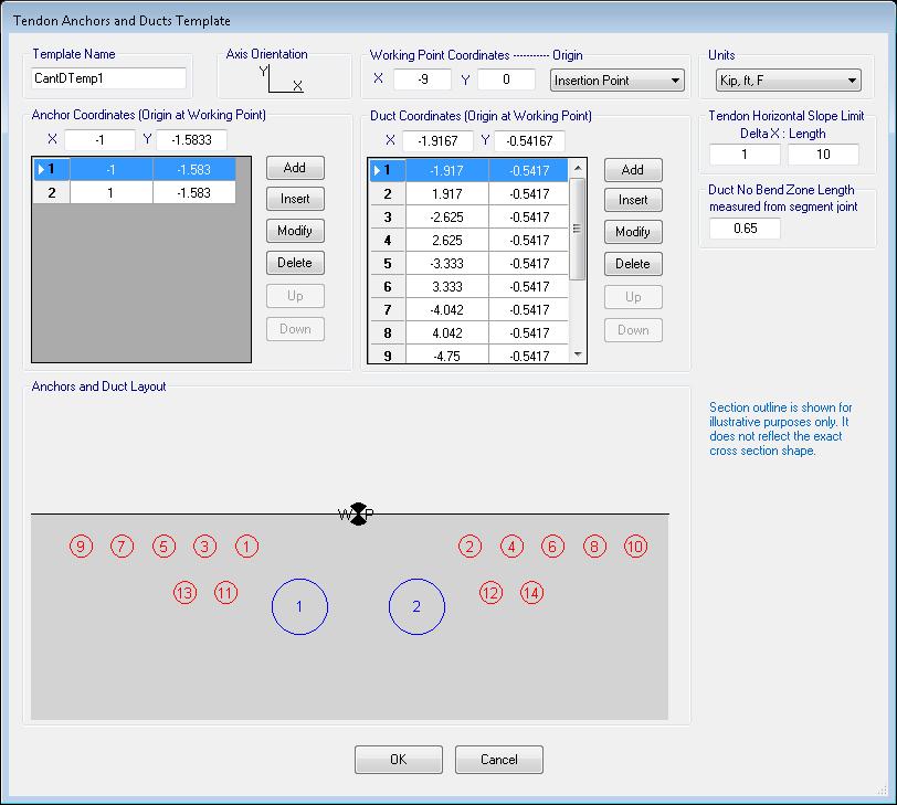
8 Cantilever Tendons Cantilever tendons can be defined only for superstructures that include balanced cantilever span discretization types. The Balanced Cantilever Pier dropdown box lists the qualifying piers. Once a balanced cantilever pier is selected the downstation and upstation tables are populated with the relevant segments and the Partial Plan Top Slab image is updated. Next the duct template should be selected. To add/modify a duct/anchor template, click the button. The duct template allows definition of maximum slope of the tendon from the centerline insertion point as it leads from the anchor location to the final duct destination. The form also allows specification of the minimum distance from the segment face where the tendon will run straight. If the slope and straight distance criteria cannot be met the tendon is plotted as red and a warning is displayed. The tendon prefix is one character that must be unique within the cantilever, bottom, and top span tendons. Lower and uppercase characters are treated as identical. Check the X check box and specify an X-coordinate to generate symmetrical tendons. The X-coordinate is measured from the centerline insertion point; for X=0 the tendons will be mirrored about the centerline insertion point. The tendon parameters such as tendon material, area, jacking force, etc can be modified by clicking the Add/Modify Tendon Parameters button. To define cantilever tendons, specify the number of tendons that are anchored at each segment face. The total number of tendons anchored in downstation segments must equal the number of tendons anchored in upstation segments. If the count does not match the verification displays the symbol and no tendons are plotted. By clicking the Autocorrect button the defined anchored tendon numbers are adjusted to match the count. The number of tendons that can be anchored at each segment face is limited by the number of anchors defined in the duct template. To add/modify anchors click on the Tendon Duct Template button. The tendon is always defined as anchored in the lowest available anchor number and positioned in the lowest available duct number. The tendons that are anchored in segments closer to the pier are generated first followed by tendons anchored in segments further away from the pier. Each tendon must cross the pier centerline. Tendons that do not satisfy those criteria can be defined as general tendons. There are two plots that help to visualize the tendons as they are being generated. On the left is the Partial Plan Top Slab and on the right a rotated Partial Section Top Slab. The horizontal and vertical scales do not match and are calculated automatically to include all defined segments, ducts and anchors. The ducts are shown in green and anchors in blue. The plot options allow hiding or showing of the working point (WP) and mirrored tendons when applicable. The working point is defined on the Tendon Duct Template form. Page 8 of 13

9 Page 9 of 13
10 Bottom Span Tendons Bottom tendons can be defined in a superstructure that includes any type of spans. The span tendons are defined on a span basis, meaning that the tendon cannot cross the centerline pier to another span. Tendons that do not satisfy those criteria can be defined as General tendons. The Span drop down list contains the qualifying spans. Once a span is selected the downstation and upstation drop down lists are populated with the relevant segments and the Partial Plan Bottom Slab image is updated. Next the duct template should be selected. To add/modify a duct/anchor template click on the button. The duct template allows definition of the maximum slope of the tendon from the centerline insertion point as it leads from the anchor location to the final duct destination. The form also allows specification of the minimum distance from the segment face where the tendon will run straight. If the slope and straight distance criteria cannot be met the tendon is plotted as red and a warning is displayed. The tendon prefix is one character that must be unique within the cantilever, bottom, and top span tendons. Lower and uppercase characters are treated as identical. Check the X check box and specify an X-coordinate to generate symmetrical tendons. The X-coordinate is measured from the centerline insertion point. For X=0 the tendons will be mirrored about the centerline insertion point. The tendon parameters such as tendon material, area, jacking force, etc can be modified by clicking the Add/Modify Tendon Parameters button. To define bottom span tendons, select the downstation and upstation segments in which the tendon is anchored. If the tendon is not anchored directly at the segment end specify an offset value to locate the anchor inside the segment. The number of tendons that can be anchored at each segment is limited by the number of anchors defined in the duct template. To add/modify anchors click on the Tendon Duct Template button. The tendon is always defined as anchored in the lowest available anchor number and positioned in the lowest available duct number. The tendons that are specified in the first row of the table are generated first followed by tendons specified in the subsequent rows. Since the ducts and anchors are defined relative to the bottom left or right corner of the box section, the generated bottom slab tendons follow the variation of the bottom slab width and of the section depth. When the Plot Relative to WP option is selected there are two plots that help to visualize the tendons as they are being generated. On the left is Partial Plan Bottom Slab and on the right a rotated Partial Section Bottom Slab. The horizontal and vertical scales do not match and are calculated automatically to include all defined segments, ducts and anchors. The ducts are shown in green and anchors in blue. The Relative to Bottom Slab Edge and Show Entire Bottom Slab plot options hide the rotated Partial Section Bottom Slab image and the edge(s) of the bottom slab are shown at its true location. Page 10 of 13

11 Page 11 of 13
12 Top Span Tendons Top tendons can be defined in a superstructure that includes any type of spans. The span tendons are defined on a span basis, meaning that the tendon cannot cross the centerline pier to another span. Tendons that do not satisfy those criteria can be defined as General tendons. The Span dropdown list contains the qualifying spans. Once a span is selected, the downstation and upstation dropdown lists are populated with the relevant segments and the Partial Plan Top Slab image is updated. Next the duct template should be selected. To add/modify a duct/anchor template click on the button. The duct template allows definition of the maximum slope of the tendon from the centerline insertion point as it leads from the anchor location to the final duct destination. The form also allows specification of the minimum distance from the segment face where the tendon will run straight. If the slope and straight distance criteria cannot be met, the tendon is plotted as red and a warning is displayed. The tendon prefix is one character that must be unique within the cantilever, top, and top span tendons. Lower and uppercase characters are treated as identical. Check the X check box and specify an X-coordinate to generate symmetrical tendons. The X-coordinate is measured from the centerline insertion point. For X=0 the tendons will be mirrored about the centerline insertion point. The tendon parameters such as tendon material, area, jacking force, etc can be modified by clicking on the Add/Modify Tendon parameters button. To define top span tendons, select the downstation and upstation segments in which the tendon is anchored. If the tendon is not anchored directly at the segment end specify an offset value to locate the anchor inside the segment. The number of tendons that can be anchored at each segment is limited by the number of anchors defined in the duct template. To add/modify anchors click the Tendon Duct Template button. The tendon is always defined as anchored in the lowest available anchor number and positioned in the lowest available duct number. The tendons that are specified in the first row of the table are generated first followed by tendons specified in the subsequent rows. There are two plots that help to visualize the tendons as they are being generated. On the left is Partial Plan Top Slab and on the right a rotated Partial Section Top Slab. The horizontal and vertical scales do not match and are calculated automatically to include all defined segments, ducts, and anchors. The ducts are shown in green and anchors in blue. Page 12 of 13

13 Page 13 of 13
Segmental Bridge Technology Established and Evolving. W. Jay Rohleder, Jr, P.E., S.E. Senior Vice President / Project Development FIGG
 1 Segmental Bridge Technology Established and Evolving W. Jay Rohleder, Jr, P.E., S.E. Senior Vice President / Project Development FIGG 2 Segmental Bridge Topics Addressed Definition of concrete segmental
AutoCAD Civil 3D 2009 ESSENTIALS
 AutoCAD Civil 3D 2009 ESSENTIALS SDC PUBLICATIONS Schroff Development Corporation www.schroff.com Better Textbooks. Lower Prices. Alignments and Profiles Section 2: Profiles In this section you learn how
How to define Graph in HDSME
 How to define Graph in HDSME HDSME provides several chart/graph options to let you analyze your business in a visual format (2D and 3D). A chart/graph can display a summary of sales, profit, or current
Subdivision Cross Sections and Quantities
 NOTES Module 11 Subdivision Cross Sections and Quantities Quantity calculation and cross section generation are required elements of subdivision design projects. After the design is completed and approved
Autodesk Advance Steel. Drawing Style Manager s guide
 Autodesk Advance Steel Drawing Style Manager s guide TABLE OF CONTENTS Chapter 1 Introduction... 5 Details and Detail Views... 6 Drawing Styles... 6 Drawing Style Manager... 8 Accessing the Drawing Style
SolidWorks 95 User s Guide
 SolidWorks 95 User s Guide Disclaimer: The following User Guide was extracted from SolidWorks 95 Help files and was not originally distributed in this format. All content 1995, SolidWorks Corporation Contents
Advance Steel. Drawing Style Manager s guide
 Advance Steel Drawing Style Manager s guide TABLE OF CONTENTS Chapter 1 Introduction...7 Details and Detail Views...8 Drawing Styles...8 Drawing Style Manager...9 Accessing the Drawing Style Manager...9
Lesson 17. The Focus of this lesson is:
 The Focus of this lesson is: Inserting beams between frames to support Roof Top Units or concentrated loads Loading the roof beams so they design Locating a roof framed opening Lesson Comments: This lesson
PRECAST CONCRETE STRUCTURES
 PRECAST CONCRETE STRUCTURES 1. INTRODUCTION The concept of precast (also known as prefabricated ) construction includes those buildings, where the majority of structural components are standardized and
Prasanth. Lathe Machining
 Lathe Machining Overview Conventions What's New? Getting Started Open the Part to Machine Create a Rough Turning Operation Replay the Toolpath Create a Groove Turning Operation Create Profile Finish Turning
50.24 Type, Size and Location Plans for Culverts, Bridges and Culvert Bridges
 50.24 Culverts, Bridges and Culvert Bridges Type, Size and Location (T, S & L) Plans shall be required for all Bridges, Culvert Bridges and Culverts of eight-foot (8') clear span or greater as follows:
Advance Steel. Tutorial
 Advance Steel Tutorial Table of contents About this tutorial... 7 How to use this guide...9 Lesson 1: Creating a building grid...10 Step 1: Creating an axis group in the X direction...10 Step 2: Creating
Getting Started Guide
 SOLIDWORKS Getting Started Guide SOLIDWORKS Electrical FIRST Robotics Edition Alexander Ouellet 1/2/2015 Table of Contents INTRODUCTION... 1 What is SOLIDWORKS Electrical?... Error! Bookmark not defined.
CHAPTER 15. Cross Section Sheets. None, except batch processing of an input file.
 CHAPTER 15 Cross Section Sheets 15.1 Introduction Objectives Project Manager Menu Bar Application Learn the procedures for laying out cross section sheets. Cross Section Sheets None, except batch processing
SolidWorks Part I - Basic Tools SDC. Includes. Parts, Assemblies and Drawings. Paul Tran CSWE, CSWI
 SolidWorks 2015 Part I - Basic Tools Includes CSWA Preparation Material Parts, Assemblies and Drawings Paul Tran CSWE, CSWI SDC PUBLICATIONS Better Textbooks. Lower Prices. www.sdcpublications.com Powered
Existing and Design Profiles
 NOTES Module 09 Existing and Design Profiles In this module, you learn how to work with profiles in AutoCAD Civil 3D. You create and modify profiles and profile views, edit profile geometry, and use styles
OpenBridge Modeler: What is it and how can I use it today?
 2015 Bentley Systems, Incorporated OpenBridge Modeler: What is it and how can I use it today? Steve Willoughby, Senior Application Engineer Agenda: Introducing OpenBridge Modeler OpenBridge Modeler Features
Chapter 23. Signing and Pavement Marking Plans
 Chapter 23 Signing and Pavement Marking Plans 23.1 General... 23-3 23.2 Key Sheet... 23-4 23.3 Signature Sheet... 23-4 23.4 Tabulation of Quantities and Pay Item Notes... 23-4 23.4.1 Standard Notes...
Release Notes - Fixes in Tekla Structures 2016i PR1
 Release Notes - Fixes in Tekla Structures 2016i PR1, you can now set the to either or. is modified., the ID of the connection plate is not changed anymore when the connection now uses normal rebar groups
Example Application C H A P T E R 4. Contents
 C H A P T E R 4 Example Application This chapter provides an example application of how to perform steady flow water surface profile calculations with HEC-RAS. The user is taken through a step-by-step
Excel Lab 2: Plots of Data Sets
 Excel Lab 2: Plots of Data Sets Excel makes it very easy for the scientist to visualize a data set. In this assignment, we learn how to produce various plots of data sets. Open a new Excel workbook, and
Student + Instructor:
 DRAFT OF DEMO FOR The following set of instructions are an optional replacement for the Section Views in SolidWorks. This demo should help prepare the students for the Out of Class HW Student + Instructor:
Table of Contents. What's New in GRAITEC Advance BIM Designers 2018 R2 ADVANCE BIM DESIGNERS CONCRETE SERIES... 4
 What's New 2018 R2 Table of Contents ADVANCE BIM DESIGNERS CONCRETE SERIES... 4 REINFORCED CONCRETE FOOTING DESIGNER... 4 Multi-layer soil calculation... 4 Bottom Constructive Reinforcement... 5 REINFORCED
Revit Structure 2012 Basics:
 SUPPLEMENTAL FILES ON CD Revit Structure 2012 Basics: Framing and Documentation Elise Moss autodesk authorized publisher SDC PUBLICATIONS www.sdcpublications.com Schroff Development Corporation Structural
Lesson 7: Roof Height Change buildings; changing bracing; WideBay Roof Secondary; soldier columns; snow drift.
 127 Lesson 7: Roof Height Change buildings; changing bracing; WideBay Roof Secondary; soldier columns; snow drift. Input an Endwall-to Endwall Roof Height Change (Low Building for Office, High Building
Using Siemens NX 11 Software. The connecting rod
 Using Siemens NX 11 Software The connecting rod Based on a Catia tutorial written by Loïc Stefanski. At the end of this manual, you should obtain the following part: 1 Introduction. Start NX 11 and open
Release Notes - Fixes in Tekla Structures 2016i SP1
 Release Notes - Fixes in Tekla Structures 2016i SP1 is modified., the ID of the connection plate is not changed anymore when the connection now uses normal rebar groups instead of tapered groups., the
BRIDGE TYPE CONCEPT EVALUATION
 SD44/PLATTE-WINNER BRIDGE CORRIDOR STUDY AND ENVIRONMENTAL ASSESSMENT Agreement No. 410583, Work Order PD-19-16 Project Nos. HP5596(19); P0044()290, PCN 05X0 PROJECT MEMORANDUM BRIDGE TYPE CONCEPT EVALUATION
VTube-LASER Quick Start Guide
 VTube-LASER Quick Start Guide This guide shows how to import a STEP file and then MEASURE and qualify demo tube 4 using the standard UNISCAN method of measuring. The steps in this workflow are from version
User Guide V10 SP1 Addendum
 Alibre Design User Guide V10 SP1 Addendum Copyrights Information in this document is subject to change without notice. The software described in this document is furnished under a license agreement or
BSketchList 3D. BSoftware for the Design and Planning of Cabinetry and Furniture RTD AA. SketchList Inc.
 1 BSketchList 3D 1 BSoftware for the Design and Planning of Cabinetry and Furniture 2 RTD10000651AA 2 Overview of SketchList 3D SketchList 3D is a software program that aids woodworkers in the design and
1.6.7 Add Arc Length Dimension Modify Dimension Value Check the Sketch Curve Connectivity
 Contents 2D Sketch... 1 1.1 2D Sketch Introduction... 1 1.1.1 2D Sketch... 1 1.1.2 Basic Setting of 2D Sketch... 2 1.1.3 Exit 2D Sketch... 4 1.2 Draw Common Geometry... 5 2.2.1 Points... 5 2.2.2 Lines
Zooming in on Architectural Desktop Layouts Alexander L. Wood
 December 2-5, 2003 MGM Grand Hotel Las Vegas Alexander L. Wood Code BD41-3L Take advantage of both AutoCAD and Autodesk Architectural Desktop Layout features. We'll look at the basics of setting up AutoCAD
DRAFT Solid Edge ST4 Update Training Draft
 DRAFT Solid Edge ST4 Update Training Draft Presented by: Steve Webb Topics Parts List Table Titles Column Headers Headers Merging Header Rotate Cell Aspect Ratio Cell Formatting Overriding Disabled Cells
Learning Guide. ASR Automated Systems Research Inc. # Douglas Crescent, Langley, BC. V3A 4B6. Fax:
 Learning Guide ASR Automated Systems Research Inc. #1 20461 Douglas Crescent, Langley, BC. V3A 4B6 Toll free: 1-800-818-2051 e-mail: support@asrsoft.com Fax: 604-539-1334 www.asrsoft.com Copyright 1991-2013
Revit Structure 2013 Basics
 Revit Structure 2013 Basics Framing and Documentation Elise Moss Supplemental Files SDC P U B L I C AT I O N S Schroff Development Corporation Better Textbooks. Lower Prices. www.sdcpublications.com Tutorial
1 Sketching. Introduction
 1 Sketching Introduction Sketching is arguably one of the more difficult techniques to master in NX, but it is well-worth the effort. A single sketch can capture a tremendous amount of design intent, and
Import/Export of tendons in module StatiCa Tendon
 IDEA Tutorial Import/Export of tendons in module StatiCa Tendon by using formats DXF, TXT and table format Import/Export of tendons in module StatiCa Tendon 1 Contents 1. Terminology... 2 2. Import...
Exercise 1: The AutoCAD Civil 3D Environment
 Exercise 1: The AutoCAD Civil 3D Environment AutoCAD Civil 3D Interface Object Base Layer Object Component Layers 1-1 Introduction to Commercial Site Grading Plans AutoCAD Civil 3D Interface AutoCAD Civil
Completed project drawing (dimensions added for reference)
") CHAPTER 5 Fundamentals IV PROJECT EXERCISE This project exercise provides point-by-point instructions for setting up the drawing with layers and then creating the objects shown in the accompanying figure.
CHAPTER 5 Fundamentals IV PROJECT EXERCISE This project exercise provides point-by-point instructions for setting up the drawing with layers and then creating the objects shown in the accompanying figure.
IDEA Connection 8. User guide. IDEA Connection user guide
 IDEA Connection user guide IDEA Connection 8 User guide IDEA Connection user guide Content 1.1 Program requirements... 5 1.2 Installation guidelines... 5 2 User interface... 6 2.1 3D view in the main window...
06/17/02 Page 1 of 12
 Understanding the Graphical User Interface When you start AutoCAD, the AutoCAD window opens. The window is your design work space. It contains elements that you use to create your designs and to receive
The $13.2 billion Central Artery/Tunnel Project (CA/
 PART 2 Central Artery/Tunnel Project: Innovative Use of Precast Segmental Technology Paul J. Towell, P.E. Senior Bridge Engineer Bechtel/Parsons Brinckerhoff New York, New York Part 1 of this series of
AASHTOWare Bridge Design Training Weld Design and Weld Fatigue Analysis (BrD 6.5) Topics Covered Part 1: Weld Design/Design Review
 Topics Covered Part 1: Weld Design/Design Review") AASHTOWare Bridge Design Training Weld Design and Weld Fatigue Analysis (BrD 6.5) Topics Covered Flange to web weld LRFD Design Flange to web weld LRFD Design Review Weld Fatigue Analysis Part 1: Weld
AASHTOWare Bridge Design Training Weld Design and Weld Fatigue Analysis (BrD 6.5) Topics Covered Flange to web weld LRFD Design Flange to web weld LRFD Design Review Weld Fatigue Analysis Part 1: Weld
PASS Sample Size Software. These options specify the characteristics of the lines, labels, and tick marks along the X and Y axes.
 Chapter 940 Introduction This section describes the options that are available for the appearance of a scatter plot. A set of all these options can be stored as a template file which can be retrieved later.
Certified SOLIDWORKS Professional Advanced Preparation Materials
 Includes Preparation for Five Advanced Certification Exams Certified SOLIDWORKS Professional Advanced Preparation Materials Sheet Metal, Weldments, Surfacing, Mold Tools and Drawing Tools SOLIDWORKS 2016
Principles and Applications of Microfluidic Devices AutoCAD Design Lab - COMSOL import ready
 Principles and Applications of Microfluidic Devices AutoCAD Design Lab - COMSOL import ready Part I. Introduction AutoCAD is a computer drawing package that can allow you to define physical structures
IDEA CSS 7 General cross-section
 IDEA CSS User Guide IDEA CSS 7 General cross-section User guide IDEA CSS User Guide Content 1.1 Program requirements... 3 1.2 Installation guidelines... 3 2 Basic Terms... 4 3 User interface... 5 3.1 Control
How to Build a Game Console. David Hunt, PE
 How to Build a Game Console David Hunt, PE davidhunt@outdrs.net Covering: Drafts Fillets Shells Patterns o Linear o Circular Using made-for-the-purpose sketches to define reference geometry Using reference
Walls. Section. Walls. When you finish this section, you should understand the following:
 GOLDMC03_132283433X 8/24/06 2:23 PM Page 123 Section 3 Walls When you finish this section, you should understand the following: How to place a wall object. How to change walls by dynamically pulling on
Alibre Design Tutorial: Loft, Extrude, & Revolve Cut Loft-Tube-1
 Alibre Design Tutorial: Loft, Extrude, & Revolve Cut Loft-Tube-1 Part Tutorial Exercise 5: Loft-Tube-1 [Complete] In this Exercise, We will set System Parameters first, then part options. Then, in sketch
File Button 9 Font Creator 251. Gifts in the Hoop 413 Grid 53 Grouping 93. Installing Adding a shortcut 24 Checking for updates 23 Full version 17
 A Alignment Aligning multiple pieces 345 Alignment is similar to Applique position 340 Different color for alignment lines 345 Using Thumb tacks for Alignment 340 Why Straight Alignment lines 344 Applique
Chapter 6 Title Blocks
 Chapter 6 Title Blocks In previous exercises, every drawing started by creating a number of layers. This is time consuming and unnecessary. In this exercise, we will start a drawing by defining layers
Imaging Features Available in HTML5. it just makes sense
 Imaging Features Available in HTML5 it just makes sense August, 2018 Imaging Features Available in HTML5 As part of the 5.2 SP1 release, the Images functionality is now available in HTML5 and provides
Autodesk Architectural Desktop Functionality for the Autodesk Building Systems User
 11/28/2005-1:00 pm - 2:30 pm Room:N. Hemispheres (Salon A1) (Dolphin) Walt Disney World Swan and Dolphin Resort Orlando, Florida Autodesk Architectural Desktop Functionality for the Autodesk Building Systems
Stratigraphy Modeling Boreholes and Cross. Become familiar with boreholes and borehole cross sections in GMS
 v. 10.3 GMS 10.3 Tutorial Stratigraphy Modeling Boreholes and Cross Sections Become familiar with boreholes and borehole cross sections in GMS Objectives Learn how to import borehole data, construct a
Chapter 5 Sectional Views
 Chapter 5 Sectional Views There are a number of different types of sectional views that can be drawn. A few of the more common ones are: full sections, half sections, broken sections, rotated or revolved
Introduction to Sheet Metal Features SolidWorks 2009
 SolidWorks 2009 Table of Contents Introduction to Sheet Metal Features Base Flange Method Magazine File.. 3 Envelopment & Development of Surfaces.. 14 Development of Transition Pieces.. 23 Conversion to
Construction Tolerances - The following tolerances apply to cast-in-place structures:
 00540.40(b) Construction 00540.40 Tolerances - The following tolerances apply to cast-in-place structures: (a) Foundation Footings: (1) Lateral Alignment: Actual (as cast) location of the center of gravity:
What's New in Autodesk Architectural Desktop 2004? Kelcey Lemon
 December 2-5, 2003 MGM Grand Hotel Las Vegas What's New in Autodesk Architectural Desktop 2004? Kelcey Lemon BD31-5L Autodesk Architectural Desktop 2004 has well over 300 new features and enhancements.
Table of contents. User interface 1: Customizable tool palette... 6 User interface 2: General GUI improvements... 7
 Table of contents WELCOME TO ADVANCE CONCRETE 2014... 5 USER INTERFACE ENHANCEMENTS... 6 User interface 1: Customizable tool palette... 6 User interface 2: General GUI improvements... 7 MODELING... 10
Sheet Metal OverviewChapter1:
 Sheet Metal OverviewChapter1: Chapter 1 This chapter describes the terminology, design methods, and fundamental tools used in the design of sheet metal parts. Building upon these foundational elements
Using Layers and Object Properties
 Using Layers and Object Properties In This Chapter 10 Layers are like transparent overlays on which you organize and group different kinds of drawing information. The objects you create have common properties
Hydraulics and Floodplain Modeling Managing HEC-RAS Cross Sections
 v. 9.1 WMS 9.1 Tutorial Hydraulics and Floodplain Modeling Managing HEC-RAS Cross Sections Modify cross sections in an HEC-RAS model to use surveyed cross section data Objectives Build a basic HEC-RAS
Block References and Attributes
 CHAPTER 11 Block References and Attributes PROJECT EXERCISE 11A This project exercise provides point-by-point instructions for creating the objects shown in Figure P11A 1. In this exercise, you will apply
8 Working Drawings in AutoCAD
 8 Working Drawings in AutoCAD Most engineering designs consist of more than a single part. Usually there are a several or many parts that must fit and work together. When we are creating the drawings of
Output a drawing layout to a printer, a plotter, or a file. Save and restore the printer settings for each layout.
 Printing Output a drawing layout to a printer, a plotter, or a file. Save and restore the printer settings for each layout. Originally, people printed text from printers and plotted drawings from plotters.
Autocad Basics 7/28/2009. Chapter 14 - Learning Objectives
 Chapter 14 - Learning Objectives Autocad Basics Chapter 14 July 28, 2009 Use grips to stretch, copy, move, rotate, scale, and mirror objects. Edit objects using the Quick Properties panel and the Properties
CHM 152 Lab 1: Plotting with Excel updated: May 2011
 CHM 152 Lab 1: Plotting with Excel updated: May 2011 Introduction In this course, many of our labs will involve plotting data. While many students are nerds already quite proficient at using Excel to plot
Autodesk Medical Center
 Autodesk Medical Center Page 1 Contents Autodesk Medical Center... 1 Revit Projects... 3 Exercise 1 Create a new project file... 3 Datum Elements... 4 Exercise 2 Add Grids... 5 Exercise 3 Edit Levels...
Engineering & Computer Graphics Workbook Using SOLIDWORKS
 Engineering & Computer Graphics Workbook Using SOLIDWORKS 2017 Ronald E. Barr Thomas J. Krueger Davor Juricic SDC PUBLICATIONS Better Textbooks. Lower Prices. www.sdcpublications.com Powered by TCPDF (www.tcpdf.org)
Clock Exercise (Inserting Planes)
") Clock Exercise (Inserting Planes) Prerequisite Knowledge To complete this exercise you will need to be familiar with Sketching, Applying relations, Extrude Boss/ Base, Extrude cut, Applying Textures, Renaming
Clock Exercise (Inserting Planes) Prerequisite Knowledge To complete this exercise you will need to be familiar with Sketching, Applying relations, Extrude Boss/ Base, Extrude cut, Applying Textures, Renaming
Modeling an Airframe Tutorial
 EAA SOLIDWORKS University p 1/11 Difficulty: Intermediate Time: 1 hour As an Intermediate Tutorial, it is assumed that you have completed the Quick Start Tutorial and know how to sketch in 2D and 3D. If
[EC202 AutoCAD Topic Dimension] DEC 2010
![[EC202 AutoCAD Topic Dimension] DEC 2010](/thumbs/75/71849153.jpg "[EC202 AutoCAD Topic Dimension] DEC 2010") DIMENSIONING OBJECTIVES At the end of the unit you will be able to: Create linear dimensions with DIMLINEAR, DIMCONTINUE, DIMBASELINE, DIMALIGNED. Create radial dimensions with DIMDIAMETER and DIMRADIUS.
DIMENSIONING OBJECTIVES At the end of the unit you will be able to: Create linear dimensions with DIMLINEAR, DIMCONTINUE, DIMBASELINE, DIMALIGNED. Create radial dimensions with DIMDIAMETER and DIMRADIUS.
Step 1: Set up the variables AB Design. Use the top cells to label the variables that will be displayed on the X and Y axes of the graph
 Step 1: Set up the variables AB Design Use the top cells to label the variables that will be displayed on the X and Y axes of the graph Step 1: Set up the variables X axis for AB Design Enter X axis label
Sheet Metal OverviewChapter1:
 Sheet Metal OverviewChapter1: Chapter 1 This chapter describes the terminology, design methods, and fundamental tools used in the design of sheet metal parts. Building upon these foundational elements
Archibus Space Console
 Archibus Space Console Space Console Overview General Navigation Retrieving Floor Plans and Data Displaying Floor Plans and Data Reviewing Data Exporting Floor Plans to PDF Use the table of contents hyperlinks
Revit Structure 2014 Basics
 Revit Structure 2014 Basics Framing and Documentation Elise Moss Authorized Author SDC P U B L I C AT I O N S Better Textbooks. Lower Prices. www.sdcpublications.com Powered by TCPDF (www.tcpdf.org) Visit
IDEA Connections. User guide
 IDEA Connections user guide IDEA Connections User guide IDEA Connections user guide Content 1.1 Program requirements... 4 1.1 Installation guidelines... 4 2 User interface... 5 2.1 3D view in the main
COURSE UNIT 3. Plan Creation. Messerli EliteCAD Version
 Messerli EliteCAD Version 13 27.09.2013 COURSE UNIT 3 Plan Creation Switzerland: Austria: Germany: Messerli Informatik AG Messerli Informatik GmbH Messerli Informatik GmbH Pfadackerstrasse 6 Hamoderstraße
CBCL Limited Sheet Set Manager Tutorial 2013 REV. 02. CBCL Design Management & Best CAD Practices. Our Vision
 CBCL Limited Sheet Set Manager Tutorial CBCL Design Management & Best CAD Practices 2013 REV. 02 Our Vision To be the most respected and successful Atlantic Canada based employeeowned firm, delivering
Module 10. Assemblies and Corridors. Objectives
 NOTES Module 10 Assemblies and Corridors In this module, you learn to work with assemblies and corridors in AutoCAD Civil 3D. Corridor models are used to represent road designs in Civil 3D. An assembly
Inventor-Parts-Tutorial By: Dor Ashur
 Inventor-Parts-Tutorial By: Dor Ashur For Assignment: http://www.maelabs.ucsd.edu/mae3/assignments/cad/inventor_parts.pdf Open Autodesk Inventor: Start-> All Programs -> Autodesk -> Autodesk Inventor 2010
Evaluation Chapter by CADArtifex
 The premium provider of learning products and solutions www.cadartifex.com EVALUATION CHAPTER 2 Drawing Sketches with SOLIDWORKS In this chapter: Invoking the Part Modeling Environment Invoking the Sketching
S206E Lecture 6, 5/18/2016, Rhino 3D Architectural Modeling an overview
 Copyright 2016, Chiu-Shui Chan. All Rights Reserved. S206E057 Spring 2016 This tutorial is to introduce a basic understanding on how to apply visual projection techniques of generating a 3D model based
Getting Started with Revit
 AUTODESK Autodesk REVIT Revit TRAINING Training TUTORIAL Tutorial Getting Started with Revit FOCUS Focus KUWAIT Kuwait CAD Cad Team 2012-13 Step 01 02 Grid & levels Grid create 5 vertical grid lines grid
MWF Rafters. User Guide
 MWF Rafters User Guide September 18 th, 2018 2 Table of contents 1. Introduction... 3 1.1 Things You Should Know Before Starting... 3 1.1.1 Roof Panels Structure Orientation... 3 1.1.2 Member Selection...
Figure 1 - Motor City Electric Company Toolbar. LP Low Power HP High Power FA Fire Alarm C Communications LIT Lighting
 AutoCAD AutoCAD is the primary drawing program used by Motor City Electric Company. This program helps to engineer layouts of a buildings electrical equipment, lighting, and power that is to be sent out
Vehicle Cards. The Vehicle Cards screen is used to view cards. Authorized users may edit, create, and lock cards on this screen.
 Vehicle Cards The Vehicle Cards screen is used to view cards. Authorized users may edit, create, and lock cards on this screen. Vehicle Card Search The Vehicle Card Search section of the Vehicle Cards
Overview... 1 Displaying the Item Processing Modules Window... 1
 Credit Card Overview... 1 Displaying the Item Processing Modules Window... 1 Understanding the Item Processing Modules Window... 1 Refreshing the Item Processing Modules Window... 2 Starting Credit Card...
Lesson 4 Holes and Rounds
 Lesson 4 Holes and Rounds 111 Figure 4.1 Breaker OBJECTIVES Sketch arcs in sections Create a straight hole through a part Complete a Sketched hole Understand the Hole Tool Use Info to extract information
Introduction to Autodesk Inventor for F1 in Schools (Australian Version)
") Introduction to Autodesk Inventor for F1 in Schools (Australian Version) F1 in Schools race car In this course you will be introduced to Autodesk Inventor, which is the centerpiece of Autodesk s Digital
Introduction to Autodesk Inventor for F1 in Schools (Australian Version) F1 in Schools race car In this course you will be introduced to Autodesk Inventor, which is the centerpiece of Autodesk s Digital
The Rest of the Story: Using Autodesk Inventor Tools to Complete Facilities Design Documentation and Design
 The Rest of the Story: Using Autodesk Inventor Tools to Complete Facilities Design Documentation and Design Instructor: Mike Jolicoeur Autodesk Lab Assistants: Sachlene Singh Autodesk Steve Schuchard PMC
Segmental Bridge Construction. Segmental Bridges It s a Construction Technique with Design Implications. Plans Review Group
 Structures g Design Plans Review Group Segmental Bridge Construction Segmental Bridges It s a Construction Technique with Design Implications 2010 FDOT/FTBA Construction Conference February 23-24 Orlando,
Chief Architect X3 Training Series. Layers and Layer Sets
 Chief Architect X3 Training Series Layers and Layer Sets Save time while creating more detailed plans Why do you need Layers? Setting up Layer Lets Adding items to layers Layers and Layout Pages Layer
Sensors and Scatterplots Activity Excel Worksheet
 Name: Date: Sensors and Scatterplots Activity Excel Worksheet Directions Using our class datasheets, we will analyze additional scatterplots, using Microsoft Excel to make those plots. To get started,
DeltaCad and Your Cylinder (Shepherd s) Sundial Carl Sabanski
 Sundial Carl Sabanski") 1 The Sundial Primer created by In the instruction set SONNE and Your Cylinder Shepherd s Sundial we went through the process of designing a cylinder sundial with SONNE and saving it as a dxf file. In
1 The Sundial Primer created by In the instruction set SONNE and Your Cylinder Shepherd s Sundial we went through the process of designing a cylinder sundial with SONNE and saving it as a dxf file. In
Engineering & Computer Graphics Workbook Using SolidWorks 2014
 Engineering & Computer Graphics Workbook Using SolidWorks 2014 Ronald E. Barr Thomas J. Krueger Davor Juricic SDC PUBLICATIONS Better Textbooks. Lower Prices. www.sdcpublications.com Powered by TCPDF (www.tcpdf.org)
GW3-TRBO Affiliation Software Version 2.15 Module Book
 GW3-TRBO Affiliation Software Version 2.15 Module Book 1/17/2018 2011-2018 The Genesis Group 2 Trademarks The following are trademarks of Motorola: MOTOTRBO. Any other brand or product names are trademarks