Basic Welding Symbols and Their Location Significance
|
|
|
- Jack Sharp
- 6 years ago
- Views:
Transcription

1 Basic Welding Symbols and Their Location Significance
2 Objectives After completing this chapter, the student should be able to: Understand the basics of welding symbols List the major parts of a welding symbol Interpret weld locations Interprets welding symbol information 2012 Delmar, Cengage Learning
3 Welding Symbols Enable a designer to indicate detailed information Shorthand language Standardized by AWS Tail is added to the basic symbol for placement of specific information 2012 Delmar, Cengage Learning
4 Reference Line (Required element) Always Horizontal
5 Reference Line (Required element) Arrow
")
6 Reference Line (Required element) Arrow Tail
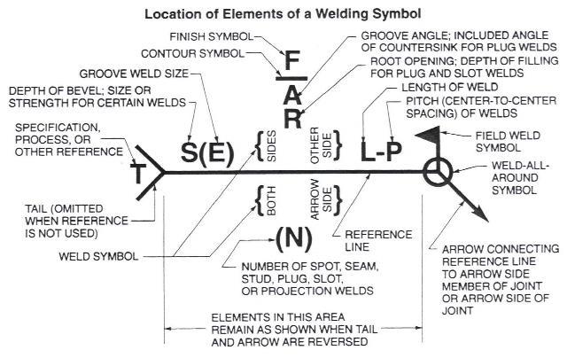
7 Reference Line must always be horizontal, Arrow points to the line or lines on drawing which clearly identify the proposed joint or weld area. Reference Line (Required element) Arrow Tail The tail of the welding symbol is used to indicate the welding or cutting processes, as well as the welding specification, procedures, or the supplementary information to be used in making the weld.
8 FIGURE Locations of specifications, processes, and other references on weld symbols. Cengage Learning Delmar, Cengage Learning
9 Location Significance of Arrow Fillet and groove welding symbols Arrow connects welding symbol reference line to one side of the joint Joint illustrated as a single line Arrow of a symbol is directed to the line Arrow side of joint is the near side of the joint Plug, slot, spot, seam, resistance, flash, upset, or projection symbols Arrow connects reference line to outer surface 2012 Delmar, Cengage Learning
10 Indicating Types of Welds Weld type classifications Fillets Grooves Flange Plug Slot Spot or projection Seam Back or backing Surfacing 2012 Delmar, Cengage Learning
11 Weld Location Arrow side, other side, and both sides Used to indicate the weld location Weld deposited on arrow side Symbol placed below the reference line Weld deposited on the other side of the joint Symbol is placed above Tail is added to designate welding specifications 2012 Delmar, Cengage Learning
12 OTHER SIDE ARROW SIDE
13
14
15
16
17 Fillet Weld Symbol Notice the Vertical line Is always located on the Left! Arrow Side And the angled line it leans towards the reference line. Other Side Both Sides No Arrow side or Other side Significance Not Used
18 Fillet Welds Dimensions of fillet welds Shown on same side of reference line as weld symbol Size of a fillet weld with unequal legs Shown in parentheses to left of symbol Intermittent fillet welds Length and pitch increments are placed to the right Used to reduce amount of welding, possible weld distortion, and to prevent a crack from spreading 2012 Delmar, Cengage Learning
19 Plug or Slot Rectangle shape Arrow Side Other Side Both Sides Not Used No Arrow side or Other side Significance Not Used
20 Plug Welds Holes in arrow side member of a joint for plug welding Indicated by placing weld symbol below the reference line Holes in the other side member Indicated by placing weld symbol above the line Diameter or size Located to the left of the symbol 2012 Delmar, Cengage Learning
21 Spot or Projection Resistance welder Arrow Side Other Side Both Sides Not Used No Arrow side or Other side Significance
22 Spot Welds Dimensions of resistance spot welds Indicated on same side of reference line as the weld symbol Dimensioned by size or strength Size: designated as weld diameter Strength: shown as minimum shear strength in pounds per spot and is shown to the left of the symbol 2012 Delmar, Cengage Learning
23 Stud Stud nail/bolt Arrow Side Other Side Not Used Both Sides Not Used No Arrow side or Other side Significance Not Used
24 Seam Arrow Side Other Side Both Sides Not Used No Arrow side or Other side Significance
25 Seam Welds Dimensions of seam welds Shown on same side of reference line as the weld symbol Size is shown with or without the inch marks to the left of the weld symbol Strength is designated as minimum acceptable shear strength in pounds per linear inch 2012 Delmar, Cengage Learning
26 Back or Backing Arrow Side Other Side Both Sides Not Used No Arrow side or Other side Significance Not Used
27 Backing Piece of metal placed on back side of a weld joint Must be thick enough to withstand the heat of the root pass May be used on butt joints, tee joints, and outside corner joints May be left on the finished weld or removed 2012 Delmar, Cengage Learning
28 Surfacing Arrow Side Other Side Not Used Both Sides Not Used No Arrow side or Other side Significance Not Used
29 Edge Arrow Side Other Side Both Sides No Arrow side or Other side Significance Not Used
30 Flanged Welds Weld symbols used where edges joined are bent to form a flange Edge flange: shown by edge flange weld symbol Corner flange welds: indicated by corner flange weld symbol Dimensions: shown on same side of reference line as weld symbol Size of flange weld: shown by a dimension placed outward from flanged dimensions 2012 Delmar, Cengage Learning
31
32 Joint strength Groove Welds Can be improved by making some type of groove preparation Seven types of grooves Can be made in one or both plates or on one or both sides Cutting the groove: weld can penetrate deeper Can be cut in base metals in a number of ways 2012 Delmar, Cengage Learning
33 Square Arrow Side Other Side Both Sides No Arrow side or Other side Significance
34 V Arrow Side Other Side Both Sides No Arrow side or Other side Significance Not Used
35 Bevel Arrow Side Other Side Both Sides No Arrow side or Other side Significance Not Used
36 U Arrow Side Other Side Both Sides No Arrow side or Other side Significance Not Used
37 J Arrow Side Other Side Both Sides No Arrow side or Other side Significance Not Used
38 Flare-V Arrow Side Other Side Both Sides No Arrow side or Other side Significance Not Used
39 Flare-Bevel Arrow Side Other Side Both Sides No Arrow side or Other side Significance Not Used
40 Scarf for Brazed Joint Arrow Side Other Side Both Sides No Arrow side or Other side Significance Not Used
41 Weld all Around Field weld Melt thru Consumable Insert (Square) Backing/Spacer (Rectangular) Contour Flush or Flat Convex Concave Backing Spacer
42 A circle at the tangent of the arrow and the reference line means welding to be all around.
43 A flag at the tangent of the reference line and arrow means Field Weld.
44
45
46 1/4 1/4
47 Depth of preparation or groove Depth of penetration 1/4 (5/16) 1/4 (5/16)
48 5/16 5/16
49
50 Weld both sides each end and 10 inches center to center in between 1/4 1/ in
51 Weld ends than 10 inch centers staggered each side 1/4 1/ in 10 in
52 Code or Standards Requirements Type, depth angle, and location of the groove determined by a code or standard Welder skill Can be a limiting factor in joint design Acceptable cost Joint design: one major way to control welding cost 2012 Delmar, Cengage Learning
53 Summary Welding symbols Meanings must be interpreted Understanding prevents over-welding Weldments must be flexible within limits 2012 Delmar, Cengage Learning
Deciphering Weld Symbols - MillerWelds
 Deciphering 91 Weld Shares Symbols When welds are specified on engineering and fabrication drawings, a cryptic set of symbols is used as a sort of shorthand for describing the type of weld, its size, and
Welding 2 go. alhuzaim_af [Type the company name] 8/2/2012
![Welding 2 go. alhuzaim_af [Type the company name] 8/2/2012](/thumbs/86/93471492.jpg "Welding 2 go. alhuzaim_af [Type the company name] 8/2/2012") 2012 Welding 2 go alhuzaim_af [Type the company name] 8/2/2012 One must try by doing the thing; for though you think you know it, you have no certainty until you try. - Sophocles 2 I would like to express
2012 Welding 2 go alhuzaim_af [Type the company name] 8/2/2012 One must try by doing the thing; for though you think you know it, you have no certainty until you try. - Sophocles 2 I would like to express
Fig. 9 Different weld positions. There are five basic types of common joints. They are
 c) Vertical - On the wall d) Horizontal - On the wall Fig. 9 Different weld positions 7.0 TYPES OF JOINTS There are five basic types of common joints. They are Butt joint Lap joint T joint Corner joint,
Welding Symbols. Faculty of Engineering Mechanical Dept.
 Welding Symbols Faculty of Engineering Mechanical Dept. Objectives 1. Know the name of the AWS & ISO standards for welding symbols 2. List the eight elements that may be found on a welding symbol 3. List
Section I. PRINT READING
 Welding.Com Welding Symbols - welding, equipment, supply, mig, tig, education, cours... Page 1 of 31 Friday March 2, 2007 Contact us at Welding.Com Advertise Here! Message Board Welding Schools Revolutionary
Blueprint Reading Basics For Welding Fabrication
 Blueprint Reading Basics For Welding Fabrication 9/14/2011 1 Definitions of Lines Lines are the basic communication tool used in blueprints. Listed below are examples of the most common lines used in blueprints
HANDS-ON PRINT READING FOR WELDERS
 HANDS-ON PRINT READING FOR WELDERS WORKBOOK Michael Mohn, CWI Technology Education Resources, LLC Monroe, Michigan HANDS-ON PRINT READING FOR WELDERS WORKBOOK Technology Education Resources, LLC Copyright
Basic terms of a welded joint are shown in Fig and the five basic types of joints are shown in Fig
 Welding is an effective method of making permanent joints between two or more metal parts. Cast iron, steel and its alloys, brass and copper are the metals that may be welded easily. Production of leak
STEEL REPAIR PROCEDURES OPERATIONS MANUAL
 STEEL REPAIR PROCEDURES OPERATIONS MANUAL New York State Department of Transportation Operations Division Office of Transportation Maintenance March, 2009 This page left intentionally blank. 2 FOREWORD
Pro/ENGINEER. WELDING SYMBOLS LIBRARY Catalog. Parametric Technology Corporation
 Pro/ENGINEER WELDING SYMBOLS LIBRARY Catalog Parametric Technology Corporation Contents Chapter 1: ANSI Generic Welding Symbols 1-1 Welding Symbols Library... 1-2 Controlling Symbol and Text Size... 1-2
COASTAL BEND COLLEGE WELDING SYLLABUS (Revised 8/10) Introduction to Blueprint Reading for Welders
 Introduction to Blueprint Reading for Welders") COASTAL BEND COLLEGE WELDING SYLLABUS (Revised 8/10) WLDG 1313: Introduction to Blueprint Reading for Welders Semester Hours: 3 Textbooks: Blueprint Reading For Welders, by A.E. Bennett & Louis J. Siy,
COASTAL BEND COLLEGE WELDING SYLLABUS (Revised 8/10) WLDG 1313: Introduction to Blueprint Reading for Welders Semester Hours: 3 Textbooks: Blueprint Reading For Welders, by A.E. Bennett & Louis J. Siy,
0.20. Record Page 1 of 19
 Page 1 of 19 Page 2 of 19 Page 3 of 19 Page 4 of 19 Page 5 of 19 ASME BPVC.III.1.ND-2015 Page 6 of 19 ð15þ Figure ND-3325-1 Some Acceptable Types of Unstayed Flat Heads and Covers GENERAL NOTE: The illustrations
Welding symbols on drawings
 Welding symbols on drawings Related titles from Woodhead s materials engineering list: Welded design theory and practice (ISBN 1 85573 537 7) A thoroughly practical text, but with sufficient theory to
Standards and Competencies
 Skill Performance The skill performance assessment includes the completion of a metal project and a demonstration of the ability to weld carbon steel, aluminum or stainless-steel project in various using
Welding symbols on drawings
 Welding symbols on drawings Related titles from Woodhead s materials engineering list: Welded design theory and practice (ISBN 1 85573 537 7) A thoroughly practical text, but with sufficient theory to
Australian Standard. Graphical symbols for general engineering. Part 3: Welding and non-destructive examination AS AS 1101.
 AS 1101.3 2005 AS 1101.3 2005 Australian Standard Graphical symbols for general engineering Part 3: Welding and non-destructive examination This Australian Standard was prepared by Committee WD-001, Welding
Trade of Metal Fabrication. Module 3: Plate Fabrication Unit 12: Duct Sections Phase 2
 Trade of Metal Fabrication Module 3: Plate Fabrication Unit 12: Duct Sections Phase 2 Table of Contents List of Figures... 4 List of Tables... 5 Document Release History... 6 Module 3 Plate Fabrication...
SMAW LESSON #1: Initiating and maintaining an arc using the scratch start method
 SMAW LESSON #1: Initiating and maintaining an arc using the scratch start method OBJECTIVE: Upon completion of this lesson the learner will be able to strike and maintain an arc using SMAW on steel plate
Inspection Kit Alignment, Measurement & Weld Measuring Gauges Model: IK-BACT13. Welders, CWI Inspectors, Instructors
 Inspection Kit Inspection Kit Alignment, Measurement & Weld Measuring Gauges Model: IK-BACT13 Brief Aluminium Case Type Size: 430mm x 290mm x 35mm Welders, CWI Inspectors, Instructors Now You Can Design
Bolted Joint Types Grip Washer
 Structural Bolting The Research Council on Structural Connections (RCSC) prepares specifications and documents related to structural connections RCSC s Specification for Structural Joints Using ASTM A325
steelwise How to choose the best welding option for skewed single-plate shear tabs.
 Designing welds for skewed shear tabs How to choose the best welding option for skewed single-plate shear tabs. By Carlo Lini, P.E. Imagine you ve been asked to design a skewed singleplate shear connection.
Elementary Dimensioning
 Elementary Dimensioning Standards Institutions ANSI - American National Standards Institute - creates the engineering standards for North America. ISO - International Organization for Standardization -
Unlimited work preparation of beams & bars
 Unlimited work preparation of beams & bars Unlimited work preparation of beams & bars Why limit yourself when everything is possible? Traditionally the design and detailing of a structure was restricted
Welding-Oxy Fuel Metals Joining
 Western Technical College 31442301 Welding-Oxy Fuel Metals Joining Course Outcome Summary Course Information Description Career Cluster Instructional Level Total Credits 1.00 Total Hours 36.00 Introduction
American Welding Soclety
 Key Words - Weld symbols, welding symbols, brazing symbols, nondestructive examination symbols ANSVAWS A2.4-98 An American National Standard Approved by American National Standards nstitute Novem ber 6,1997
WELDING FABRICATION NYS
 WELDING FABRICATION NYS PURPOSE To evaluate each contestant s preparation for employment and to recognize outstanding students for excellence and professionalism in the field of fabrication. ELIGIBILITY
LUX INSTALLATION GUIDE. LUX Panel V Groove Installation. Installation Guide. February
 LUX Panel V Groove Installation Installation Guide February 2017 www.luxpanel.ca LUX Panel V Groove Installation LUX panel steel cladding is designed to be installed vertically, horizontally, diagonally
FORWARD FUSELAGE ASSEMBLY
 SECTION 2 Finishing the Firewall RIVETS: SA5 or A5 (all rivets on the firewall, rivet head set from the engine side) SUGGESTION: First drill undersize pilot hole #30 or #40, then open with #20 SECTION
Introduction to Blueprint for Welders-1313 Course Syllabus: Spring 2015
 Introduction to Blueprint for Welders-1313 Course Syllabus: Spring 2015 Northeast Texas Community College exists to provide responsible, exemplary learning opportunities. Marcos Sánchez Office: VT: 102
FORWARD FUSELAGE SIDES & REAR TOP SKINS
 FORWARD FUSELAGE SIDES & REAR TOP SKINS WORK REPORT Step No. Check Parts / Tools Qty Preparations. 1 [ ] 6F5-3 Upper Front Longerons 2 2 [ ] 6F5-5 Heel Support 1 3 [ ] 6F5-2 Front Floor Skin 1 3 [ ] Firewall
Tool 3-1 A2 Bushing 6 Check if the bushing supports (angle iron) are properly welded with the upper part of the structure pipes. welded bushing suppor
 are properly welded with the upper part of the structure pipes. welded bushing suppor") Rope Pump MANUFACTURING checklist for quality control A Welding General 1 Check if welding jigs are used for welding of the main parts (wheel, structure frame and bushings) 2 Check if the pump parts are
Rope Pump MANUFACTURING checklist for quality control A Welding General 1 Check if welding jigs are used for welding of the main parts (wheel, structure frame and bushings) 2 Check if the pump parts are
Machine Drawing MEC-304. Dr. Shankar Sehgal Asst. Professor in Mech. Engg. UIET, Panjab University, Chandigarh
 Machine Drawing MEC-304 Dr. Shankar Sehgal Asst. Professor in Mech. Engg. UIET, Panjab University, Chandigarh Standard Abbreviations Standard Abbreviations Standard Abbreviations Standard Abbreviations
Kerkau Manufacturing. B16.5 Flange Book
 Kerkau Manufacturing B16.5 Flange Book TABLE OF CONTENTS Revision 1 Title Page Table of Contents Tolerance Page Permissible Imperfections Dimensions of Flange Facings (all pressure rating classes) Dimensions
Layout Tools. Marking and Layout Tools
 Best Welds, Contour Sales Vendor Code: BWS, CON Welders & Pipe Fitters Rap-Around Double ruled so both the top and bottom surfaces can be used for layouts - it is never upside-down! Packaged in its own
Curriculum for Mechanical Sub Overseer
 Curriculum for Mechanical Sub Overseer Council for Technical Education and Vocational Training Curriculum Development Division Sanothimi, Bhaktapur 2005 Course Structure of 15 Month Curriculum of Mechanical
WELDING FABRICATION. First, download and review the General Regulations at: updates.skillsusa.org.
 WELDING FABRICATION PURPOSE To evaluate each contestant s preparation for employment and to recognize outstanding students for excellence and professionalism in the field of fabrication. First, download
Welding Qualification/Certification
 Welding Qualification/Certification 9/14/2011 1 Index Page Number Pre-testing Procedure 3 Bend Test Procedure Coupons 4 Drawing for cutting Coupons and Back strap removal 5-9 Preparation and Testing Procedure
AutoCAD Inventor - Solid Modeling, Stress and Dynamic Analysis
 PDHonline Course G280 (15 PDH) AutoCAD Inventor - Solid Modeling, Stress and Dynamic Analysis Instructor: John R. Andrew, P.E. 2012 PDH Online PDH Center 5272 Meadow Estates Drive Fairfax, VA 22030-6658
Dowelling joints with VS 600
 No. 112 Dowelling joints with VS 600 A Description Dowelling joints with round dowels (in addition to flat dowels) are part of the standard wood joints in furniture manufacture. This joint is very stable.
INSTALLATION INSTRUCTIONS FOR INSTALLING T-SERIES EXTRA HEAVY DUTY LEVER LOCKSET
 HIGH EDGE 2 1/4"(57mm) 03079400070 INSTALLATION INSTRUCTIONS FOR INSTALLING T-SERIES EXTRA HEAVY DUTY LEVER LOCKSET IMPORTANT: THIS LOCK IS NON-HANDED. LOCK IS FACTORY PACKED PREADJUSTED FOR 1³ ₄" (45mm)
Geometric dimensioning & tolerancing (Part 1) KCEC 1101
 KCEC 1101") Geometric dimensioning & tolerancing (Part 1) KCEC 1101 Introduction Before an object can be built, complete information about both the size and shape of the object must be available. The exact shape of
Geometric dimensioning & tolerancing (Part 1) KCEC 1101 Introduction Before an object can be built, complete information about both the size and shape of the object must be available. The exact shape of
JVI Vector Connector
 The JVI Vector Connector User Guidelines 1 of 11 INTRODUCTION JVI designed the Vector Connector for use as shear and alignment connections between precast concrete elements such as double-tee flanges,
AWNING / PATIO COVER INSTALLATION INSTRUCTIONS
 AWNING / PATIO COVER INSTALLATION INSTRUCTIONS Before You Begin Read the installation instructions thoroughly before beginning the installation procedure. Perspective In the Awning Instructions, Back means
These introduction pages will give a
 HGG s Profiling Shapes Welcome to the world of Profiling Shapes. HGG s shapes have several distinct advantages as minimum grinding, easy fitting and optimised weld preparation for rapid welding and strong
CEILING-MOUNTED MONORAIL ANCHOR TRACK SYSTEM Assembly and Operation Instruction Manual
 CEILING-MOUNTED MONORAIL ANCHOR TRACK SYSTEM Assembly and Operation Instruction Manual This manual is for various mounting types and plain and trussed track profiles. ISO 9001:2008 Registered Manual 103-0075
TENANT IMPROVEMENT 16 FEBRUARY WEST 27TH STREET, 4TH FLOOR 100% CD OWNER/BID ADD 1-03/08/2018
 SECTION 055000 - PART 1 - GENERAL 1.1 RELATED DOCUMENTS A. Drawings and general provisions of the Contract, including General and Supplementary Conditions and Division 01 Specification Sections, apply
Skewed connections result when members frame to each
 Design of Skewed Connections LARRY KLOIBER and WILLIAM THORNTON ABSTRACT Skewed connections result when members frame to each other at an angle other than 90º. This paper provides some guidance in the
Installation Instructions Split Shake, Staggered Shake, Shingle, Perfection Shingle, and Shapes
 Installation Instructions Split Shake, Staggered Shake, Shingle, Perfection Shingle, and Shapes General Guidelines These instructions show one type of installation and are intended for the professional
System 3000 specifications
 System 3000 specifications Scope: Materials: Type of Bookstack: This specification covers delivery and installation of steel library shelving of the bracket type. Height, depth and accessories shall be
Credit Value 7 QCF Level 2 GLH 50. Learner pack
 QETI/007 Fabrication and welding principles Credit Value 7 QCF Level 2 GLH 50 Unit purpose/aims Learner pack This unit enables you to develop the general fabrication and welding knowledge essential to
Laser Welding System for Various 3-D Welding - Development of Coaxial Laser Welding Head -
 Laser Welding System for Various 3-D Welding - Development of Coaxial Laser Welding Head - SHUHO TSUBOTA*1 TAKASHI ISHIDE*1 MASAO WATANABE* TAKASHI AKABA* (MHI) has developed a hybrid welding head that
ACF Maintenance Bulletin. TC-200 Revision B. ACF 200 Stub Sill Underframe Inspection, Repair, and Enhancement
 ACF Maintenance Bulletin TC-200 Revision B ACF 200 Stub Sill Underframe Inspection, Repair, and Enhancement May 16, 2016 SHEET: 1 of 13 FOREWORD: This ACF Maintenance Bulletin TC-200 details the inspection
for a manual for steel detailers, engineers & fabricators, containing working drawings & details for hot-dip galvanized structures
 for a manual for steel detailers, engineers & fabricators, containing working drawings & details for hot-dip galvanized structures l b Ta f o e s t en t n Co Recommended Details for Hot-Dip Galvanized
Parkers. Tolerances on dimensions
 Aluminium and aluminium alloys - Extruded rod/bar, tube and pro les Alloy groups The division into Group I and Group II of the most commonly used general engineering alloys is specified in table 1. (Corresponding
Equilibrium. Conference Table. Installation Instruction. Revision B 11/07/16
 Equilibrium Conference Table Installation Instruction Revision B 11/07/16 Equilibrium End User Agreement Enwork Equilibrium table bases must be installed directly onto a four inch minimum thickness concrete
Dehydrator Box Build Plan
 Dehydrator Box Build Plan Cut Sheet Metal 1. Using a foot shear or similar tool, cut all the sheet metal components to the correct dimensions. For dimensions, refer to drawings LS-101F (Top/Side Panel)
Module 1C: Adding Dovetail Seams to Curved Edges on A Flat Sheet-Metal Piece
 1 Module 1C: Adding Dovetail Seams to Curved Edges on A Flat Sheet-Metal Piece In this Module, we will explore the method of adding dovetail seams to curved edges such as the circumferential edge of a
MANUFACTURING TECHNOLOGY
 MANUFACTURING TECHNOLOGY UNIT V Machine Tools Milling cutters Classification of milling cutters according to their design HSS cutters: Many cutters like end mills, slitting cutters, slab cutters, angular
Solid Part Four A Bracket Made by Mirroring
 C h a p t e r 5 Solid Part Four A Bracket Made by Mirroring This chapter will cover the following to World Class standards: Sketch of a Solid Problem Draw a Series of Lines Finish the 2D Sketch Extrude
Cobra X Q Construction Tips Construction: Bel y pan
 Cobra X Q Construction Tips : The white plastic in this kit is high impact styrene. It can be painted with most types of coatings if light coats are applied this is necessary due to the thickness of the
Table by Clay Spencer
 Table by Clay Spencer (steel scribe points) construct a horizontal line through the center of the vertical line. Draw the vertical and horizontal lines with This description covers making a small circular
Cable Railing Kit Application Guide
 Cable Railing Kit Application Guide January 2019 Nationwide Industries 10333 Windhorst Rd. Tampa, FL 33619 813.988.2628 Fax: 813.988.3465 Photo courtesy of FabWorx Framework You Will Need for Cable Railing
Welded connections Welded connections are basically the same design in AISI as in AISC. Minor differences are present and outlined below.
 Cold-Formed Steel Design for the Student E. CONNECTIONS AND JOINTS E1 General Provisions Connections shall be designed to transmit the maximum design forces acting on the connected members. Proper regard
Dimensioning. Dimensions: Are required on detail drawings. Provide the shape, size and location description: ASME Dimensioning Standards
 Dimensioning Dimensions: Are required on detail drawings. Provide the shape, size and location description: - Size dimensions - Location dimensions - Notes Local notes (specific notes) General notes ASME
LocoGear. Technical Bulletin - 14 November 28, 2003 Copyright 2003 by LocoGear LIVE STEAM CASTINGS. Tech Bulletin - 14
 LIVE STEAM CASTINGS LocoGear Tech Bulletin - 14 John D.L. Johnson 3879 Woods Walk Blvd Lake Worth, FL 33467-2359 jjohnson@locogear.com www.locogear.com Technical Bulletin - 14 November 28, 2003 Copyright
The end outcome of this curriculum is that the student will be eligible for placement under the ABANA/NOMMA agreement
 ABANA s National Curriculum. June 5 th 2011 version. This curriculum is limited in its scope and deals only with developing a blacksmith s skills in the forge environment. The lessons are exercises and
Multi-Wing Z Series Fans Blade Pitch Angle Setting Instructions
 Multi-Wing Z Series Fans Blade Pitch Angle Setting Instructions Before You Begin: To maintain balance of fan: Mark the hub castings across a joint, so the fan hub can be reassembled in the same orientation.
Part 8: The Front Cover
 Part 8: The Front Cover 4 Earpiece cuts and housing Lens cut and housing Microphone cut and housing The front cover is similar to the back cover in that it is a shelled protrusion with screw posts extruding
Unit4 31. UnitS 39. Unit 6 47
 Preface..................... xi About the Author......... xiii Acknowledgments... xiv Unit 1 1 Bases for Interpreting Drawings........ I Visible Lines............. 3 Lettering on Drawings... 3 Sketching...
Make a Safe. Description. Lesson Objectives. Assumptions. Terminology
 Youth Explore Trades Skills Make a Safe Description Welding is a vast area in the metalworking field and a widely used joining process for metal. In this activity plan students will learn how to MIG weld
Engineering & Computer Graphics Workbook Using SolidWorks 2014
 Engineering & Computer Graphics Workbook Using SolidWorks 2014 Ronald E. Barr Thomas J. Krueger Davor Juricic SDC PUBLICATIONS Better Textbooks. Lower Prices. www.sdcpublications.com Powered by TCPDF (www.tcpdf.org)
DUTCH GABLE FREESTANDING CARPORT
 DUTCH GABLE FREESTANDING CARPORT STRATCO OUTBACK ASSEMBLY INSTRUCTIONS. Your complete guide to building a FREESTANDING Outback DUTCH GABLE CARPORT BEFORE YOU START Carefully read these instructions. If
METL-VISION WINDOW SYSTEM FOR HORIZONTAL WALL PIONEERING INSULATED METAL PANEL TECHNOLOGY
 METL-VISION WINDOW SYSTEM FOR HORIZONTAL WALL Window assembly GUIDE PIONEERING INSULATED METAL PANEL TECHNOLOGY PIONEERING INSULATED METAL PANEL TECHNOLOGY CONTENTS DETAIL TITLE FILE NO. PAGE NO. INTRODUCTION..................................................................
ANSI B16.25 Fig. 1 - Maximum Envelope for Welding End Transitions
 Fig. 1 - Maximum Envelope for Welding End Transitions Notes: 1 - Where transitions using maximum slope do not intersect inside or outside surface, as shown by phantom outlines, maximum slopes shown or
Downloaded from ENGINEERING DRAWING. Time allowed : 3 hours Maximum Marks : 70
 ENGINEERING DRAWING Time allowed : 3 hours Maximum Marks : 70 Note : (i) (ii) Attempt all the questions. Use both sides of the drawing sheet, if necessary. (iii) All dimensions are in millimeters. (iv)
INSTALLATION MANUAL IOWA MOLD TOOLING CO., INC. BOX 189, GARNER, IA MANUAL PART NUMBER:
 PARTS-1 Model 24562/28562 Crane INSTALLATION MANUAL IOWA MOLD TOOLING CO., INC. BOX 189, GARNER, IA 50438-0189 641-923-3711 MANUAL PART NUMBER: 99903701 Iowa Mold Tooling Co., Inc. is an Oshkosh Truck
Engineering & Computer Graphics Workbook Using SOLIDWORKS
 Engineering & Computer Graphics Workbook Using SOLIDWORKS 2017 Ronald E. Barr Thomas J. Krueger Davor Juricic SDC PUBLICATIONS Better Textbooks. Lower Prices. www.sdcpublications.com Powered by TCPDF (www.tcpdf.org)
Connection and Tension Member Design
 Connection and Tension Member Design Notation: A = area (net = with holes, bearing = in contact, etc...) Ae = effective net area found from the product of the net area An by the shear lag factor U Ab =
LABEL & RATING OPTIONS
 LABEL & RATING OPTIONS FIRE LABELING GUIDELINES APPLICATION MAXIMUM SIZE HOURLY RATING Single Door 4'0" wide x 10'0" high Up to 3 hour 4'3" wide x 10'0" high Up to 1-1/2 hour Pair 8'0" wide x 10'0" high
User Guide V10 SP1 Addendum
 Alibre Design User Guide V10 SP1 Addendum Copyrights Information in this document is subject to change without notice. The software described in this document is furnished under a license agreement or
Assembly Instructions
 InTandem Table System November 20 InTandem Table System - Worksurface #4 x/" 4 wood screw power beam Tools Provided T-0 Extended Torx Driver T-25 Torx Driver Additional Tools Required Soft protective
ANSI ORIFICE FLANGES METAL-KOREA
 METAL-KOREA ANSI ORIFICE FLANGES ORIFICE FLANGES are widely used in conjunction with orifice meters for measuring the rate of flow of liquids and gases. They are basically the same as standard welding
INSUL-FLUE is used to reduce the danger of radiant heat from smoke pipe, flue pipe, gas vents, etc. igniting combustibles.
 INSUL-FLUE OWNER S MANUAL (6 inch) High Heat Resistant Thimble and Insulating Sleeve for Smoke Pipe When Passing Through Any Combustible Wall September 1993, Revision A INTRODUCTION CONGRATULATIONS ON
SolidWorks Navigation
 SolidWorks Basics SolidWorks Navigation Command Bar Feature Tree Model Window Simple Box Select the Front plane Create a new sketch Create a Center Rectangle from the origin Smart Dimension the length
A - Railing Frame Material Specifications
 A - Railing Frame Material Specifications NOTE: We strongly recommend stainless steel for exterior applications. R-1 8/1/02 B Stainless Steel Spacers (For Horizontal Railing Double Post End Post using
Trade of Metal Fabrication. Module 6: Fabrication Drawing Unit 13: Parallel Line Development Phase 2
 Trade of Metal Fabrication Module 6: Fabrication Drawing Unit 13: Parallel Line Development Phase 2 Table of Contents List of Figures... 4 List of Tables... 5 Document Release History... 6 Module 6 Fabrication
Advance Steel suite 6.1 / SP2
 Advance Steel suite 6.1 / SP2 This document describes only the improvements in Service Pack 2 compared to Service Pack 1. The installation of SP2 includes SP1; please see the previous document for improvements
CHAPTER 10. JOINTS Detachable and Permanent Joints
 CHAPTER 10. JOINTS 10.1 Detachable and Permanent Joints The joints of parts in apparatus, assemblies and machines vary in designated purpose, design form, and technology of manufacture. Joints are classified
INSTALLATION INSTRUCTIONS
 INSTALLATION INSTRUCTIONS TOOLS REQUIRED Rechargeable, variable speed drill 3/8 diameter drill bit 3 Robertson bits #0, #1 and #2 Slot screwdriver Non marring hammer with 1 head Level Caulk or sealant
TUBULAR FRONT END KIT INSTALLATION INSTRUCTIONS MUSTANG
 TUBULAR FRONT END KIT INSTALLATION INSTRUCTIONS 1979 2004 MUSTANG Pre-Installation Notes & Recommendations: Before disassembly, remove anything within the engine bay that can be removed; this will give
Trade of Sheet Metalwork. Module 3: Thermal Processes Unit 13: MMA Butt Weld Flat Position Phase 2
 Trade of Sheet Metalwork Module 3: Thermal Processes Unit 13: MMA Butt Weld Flat Position Phase 2 Table of Contents List of Figures... 4 List of Tables... 5 Document Release History... 6 Module 3 Thermal
ALL SEASON PATIO COVER
 ALL SEASON PATIO COVER 61 Where the All Season Patio Cover is to be attached to the home, create a level line showing where the top of the mounting rail is to be located. Install each section with the
the same information given in two different 1. Dimensions should NOT be duplicated, or Dimension Guidelines Incorrect ways.
 Dimension Guidelines 1. Dimensions should NOT be duplicated, or the same information given in two different ways. Incorrect 1. Dimensions should NOT be duplicated, or the same information given in two
SolidWorks Design & Technology
 SolidWorks Design & Technology Training Course at PHSG Ex 5. Lego man Working with part files 8mm At first glance the Lego man looks complicated but I hope you will see that if you approach a project one
SPEEDFRAME T h e s p e e d y w a y t o b e i n d i v i d u a l
 SPEEDFRAME T h e s p e e d y w a y t o b e i n d i v i d u a l T h e a l l p u r p o s e c o n s t r u c t i o n k i t SPEEDFRAME All materials are kept close to hand in this specially designed Speedframe
eb^sv=qfj_bo UNIVERSITY OF WISCONSIN - STOUT COLLEGE OF SCIENCE TECHNOLOGY ENGINEERING & MATHEMATICS Architectural Technology AEC 233
 eb^sv=qfj_bo UNIVERSITY OF WISCONSIN - STOUT COLLEGE OF SCIENCE TECHNOLOGY ENGINEERING & MATHEMATICS Architectural Technology AEC 233 Dr. Jason E. Charalambides fkqolar`qflk Heavy timber construction consists
Dura-Lock Roof System
 DLR-14 Dura-Lock Roof System Assembly and Installation Instructions Read the instructions before starting the job. They explain the steps required to produce a finished product that will meet factory specifications.
Module 1G: Creating a Circle-Based Cylindrical Sheet-metal Lateral Piece with an Overlaying Lateral Edge Seam And Dove-Tail Seams on the Top Edge
 Inventor (10) Module 1G: 1G- 1 Module 1G: Creating a Circle-Based Cylindrical Sheet-metal Lateral Piece with an Overlaying Lateral Edge Seam And Dove-Tail Seams on the Top Edge In Module 1A, we have explored
BC WELDER TRAINING PROGRAM
 BC WELDER TRAINING PROGRAM FOUNDATION AND APPRENTICESHIP LEVELS 1 AND 2 P4 (Line D): Shielded Metal Arc Welding I (SMAW I) Practical Competencies Acknowledgements & Copyright Permission The Industry Training
DUE DATE: Friday 4/6/2018 at 3:30 PM
 MECH 130 SPRING 2018 CAD LAB 4 FINAL REVISION HARDCOPIES NEEDED DUE DATE: Friday 4/6/2018 at 3:30 PM After the revised hitch, the ball and the pin parts were created from the Handout call LAB4 PART Creation,