Abaqus CAE (ver. 6.9) Contact Tutorial
|
|
|
- Emma Sharp
- 6 years ago
- Views:
Transcription
 Contact Tutorial Problem Description Note: You do not need to extrude the right vertical edge of")
1 Abaqus CAE (ver. 6.9) Contact Tutorial Problem Description Note: You do not need to extrude the right vertical edge of the sensor Hormoz Zareh 1 Portland State University, Mechanical Engineering
 3.")

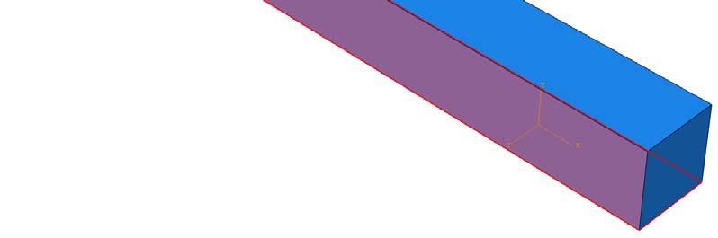
2 Analysis Steps 1. Start Abaqus and choose to create a new model database 2. In the model tree double click on the Parts node (or right click on parts and select Create) 3. In the Create Part dialog box (shown above) name the part and a. Select 3D b. Select Deformable c. Select Shell d. Select Extrusion e. Set approximate size = 50 f. Click Continue 4. Create the geometry shown below (not discussed here) 2010 Hormoz Zareh 2 Portland State University, Mechanical Engineering


3 a. Click Done b. Set Depth = 2 c. Click OK 5. Double click on the Materials node in the model tree a. Name the new material and give it a description b. Click on the Mechanical tab Elasticity Elastic c. Define Young s Modulus and the Poisson s Ratio (use SI (mm) units) d. Click OK 6. Double click on the Sections node in the model tree 2010 Hormoz Zareh 3 Portland State University, Mechanical Engineering


4 a. Name the section ShellProperties and select Shell for the category and Homogeneous for the type b. Click Continue c. Select the material created above (Steel) and set the thickness to 0.15 d. Click OK 7. Expand the Parts node in the model tree, expand the node of the part just created, and double click on Section Assignments a. Select the entire geometry, except for the vertical face, in the viewport and press Done in the prompt area b. Select the section created above (ShellProperties) c. Specify shell offset if necessary d. Click OK 8. Expand the Assembly node in the model tree and then double click on Instances a. Select Dependent for the instance type b. Click OK 2010 Hormoz Zareh 4 Portland State University, Mechanical Engineering


5 9. Double click on the Steps node in the model tree a. Name the step, set the procedure to General, select Static, General, and click Continue b. Accept the default settings 10. Double click on the BCs node in the model tree a. Name the boundary conditioned Fixed and select Symmetry/Antisymmetry/Encastre for the type b. Select the horizontal edges on the vertical surface and click Done c. Select ENCASTRE for the boundary condition and click OK 2010 Hormoz Zareh 5 Portland State University, Mechanical Engineering


6 11. Double click on the BCs node in the model tree a. Name the boundary conditioned Disp and select Displacement/Rotation for the type b. Select the top edge of the triangular portion of the geometry c. Set the y displacement to Hormoz Zareh 6 Portland State University, Mechanical Engineering


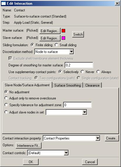
7 12. Double click on the Interaction Properties node in the model tree a. Name the interaction properties and select Contact for the type b. On the Mechanical tab Select Tangential Behavior i. Set the friction formulation to Frictionless c. On the Mechanical tab Select Normal Behavior i. Because the surfaces do not start in contact, change the constraint enforcement method to Penalty 13. Double click on the Interactions node in the model tree a. Name the interaction, select Surface to surface contact, and click continue b. For the master surface select the lower portion of the geometry and click done i. While applying the fixed displacement, the nodes at the tip of the upper portion of the geometry will make contact at an unknown location on the lower surface ii. Nodes on the slave surface cannot penetrate the surface formed by the element faces on the master surface c. Select the color of the surface corresponding to the top surface d. For the slave surface, set the slave type to Surface e. Select the upper portion of the geometry at the free end and click done f. Select the color of the surface corresponding to the bottom surface g. Change the contact interaction properties to the one created above (if not already done) 2010 Hormoz Zareh 7 Portland State University, Mechanical Engineering


8 2010 Hormoz Zareh 8 Portland State University, Mechanical Engineering


 and its description are given below the element")

9 14. In the model tree double click on Mesh for the Arch part, and in the toolbox area click on the Assign Element Type icon a. Select the portion of the geometry associated with the boundary conditions and load b. Select Standard for element type c. Select Linear for geometric order d. Select Shell for family e. Note that the name of the element (S4R) and its description are given below the element controls f. Select OK 15. In the toolbox area click on the Assign Mesh Controls icon a. Select the portion of the geometry associated with the boundary conditions and load b. Change the element shape to Quad c. Change the technique to Structured 2010 Hormoz Zareh 9 Portland State University, Mechanical Engineering


10 16. In the toolbox area click on the Seed Part icon a. Set the approximate global size to In the toolbox area click on the Mesh Region icon b. Select the entire geometry, except for the vertical face c. Select Done 18. In the model tree double click on the Job node a. Name the job switch b. Give the job a description 2010 Hormoz Zareh 10 Portland State University, Mechanical Engineering


 before resolving")

11 19. In the model tree right click on the job just created and select Submit d. Ignore the message about unmeshed portions of the geometry e. While Abaqus is solving the problem right click on the job submitted, and select Monitor f. In the Monitor window check that there are no errors or warnings i. If there are errors, investigate the cause(s) before resolving ii. If there are warnings, determine if the warnings are relevant, some warnings can be safely ignored 20. In the model tree right click on the submitted and successfully completed job, and select Results 2010 Hormoz Zareh 11 Portland State University, Mechanical Engineering


12 21. Display the deformed contour of the (Von) Mises stress overlaid with the undeformed geometry a. In the toolbox area click on the following icons i. Plot Contours on Deformed Shape ii. Allow Multiple Plot States iii. Plot Undeformed Shape 22. In the toolbox area click on the Common Plot Options icon a. Set the Deformation Scale Factor to 1 b. Click OK 23. To change the output being displayed, in the menu bar click on Results Field Output a. Select the contact pressure at surface nodes (CPRESS) b. Click OK 2010 Hormoz Zareh 12 Portland State University, Mechanical Engineering


13 2010 Hormoz Zareh 13 Portland State University, Mechanical Engineering
Abaqus/CAE (ver. 6.14*) Plate/Shell Tutorial
 Plate/Shell Tutorial") Abaqus/CAE (ver. 6.14*) Plate/Shell Tutorial Problem Description The aluminum arch (E = 79 GPa, ν = 0.33) shown below is completely clamped along the flat faces. The arch supports a pressure of 100 MPa.
Abaqus/CAE (ver. 6.14*) Plate/Shell Tutorial Problem Description The aluminum arch (E = 79 GPa, ν = 0.33) shown below is completely clamped along the flat faces. The arch supports a pressure of 100 MPa.
Abaqus Beam Tutorial (ver. 6.12)
") Abaqus Beam Tutorial (ver. 6.12) Problem Description The two-dimensional bridge structure is simply supported at its lower corners. The structure is composed of steel T-sections (E = 210 GPa, ν = 0.25)
Abaqus Beam Tutorial (ver. 6.12) Problem Description The two-dimensional bridge structure is simply supported at its lower corners. The structure is composed of steel T-sections (E = 210 GPa, ν = 0.25)
Quasi-static Contact Mechanics Problem
 Type of solver: ABAQUS CAE/Standard Quasi-static Contact Mechanics Problem Adapted from: ABAQUS v6.8 Online Documentation, Getting Started with ABAQUS: Interactive Edition C.1 Overview During the tutorial
TUTORIAL 4: Combined Axial and Bending Problem Sketch Path Sweep Initial Project Space Setup Static Structural ANSYS
 TUTORIAL 4: Combined Axial and Bending Problem In this tutorial you will learn how to draw a bar that has bends along its length and therefore will have both axial and bending stresses acting on cross-sections
Using Siemens NX 11 Software. The connecting rod
 Using Siemens NX 11 Software The connecting rod Based on a Catia tutorial written by Loïc Stefanski. At the end of this manual, you should obtain the following part: 1 Introduction. Start NX 11 and open
Introduction to ANSYS Mechanical
 Workshop 5.2 Beam Connections 15.0 Release Introduction to ANSYS Mechanical 1 2014 ANSYS, Inc. February 12, 2014 Goals Workshop 5-2 consists of a flange containing 2 parts. The fasteners holding the flange
Workshop 7.1 Linear Structural Analysis
 Workshop 7.1 Linear Structural Analysis 16.0 Release Introduction to ANSYS Mechanical 1 2015 ANSYS, Inc. September 15, 2015 Goals Workshop 7.1 consists of a 5 part assembly representing an impeller type
Converting a solid to a sheet metal part tutorial
 Converting a solid to a sheet metal part tutorial Introduction Sometimes it is easier to start with a solid and convert it to create a sheet metal part. This tutorial will guide you through the process
Chapter 1. Creating, Profiling, Constraining, and Dimensioning the Basic Sketch. Learning Objectives. Commands Covered
 Chapter 1 Creating, Profiling, Constraining, and Dimensioning the Basic Sketch Learning Objectives After completing this chapter, you will be able to: Draw the basic outline (sketch) of designer model.
Module 2.1, 2.2 Review. EF101 Analysis & Skills Module 2.3. Sketched Features and Operations. On-line Help Two Locations
 EF101 Analysis & Skills Module 2.3 Engineering Graphics Revolved Features Placed Features Work Features Module 2.1, 2.2 Review What are the three types of operations for adding features to the base feature?
< Then click on this icon on the vertical tool bar that pops up on the left side.
 Pipe Cavity Tutorial Introduction The CADMAX Solid Master Tutorial is a great way to learn about the benefits of feature-based parametric solid modeling with CADMAX. We have assembled several typical parts
Files required to restart an analysis (Abaqus/Explicit)
") RESTARTING CATEGORIES: 1-Continuing with additional steps If the previous analysis completed successfully and, having viewed the results, you want to add additional steps to the load history, the specified
RESTARTING CATEGORIES: 1-Continuing with additional steps If the previous analysis completed successfully and, having viewed the results, you want to add additional steps to the load history, the specified
Proprietary and restricted rights notice
 Proprietary and restricted rights notice This software and related documentation are proprietary to Siemens Product Lifecycle Management Software Inc. 2012 Siemens Product Lifecycle Management Software
Designing in the context of an assembly
 SIEMENS Designing in the context of an assembly spse01670 Proprietary and restricted rights notice This software and related documentation are proprietary to Siemens Product Lifecycle Management Software
Top Down Assembly Modeling Release Wildfire 2.0
 Top Down Assembly Modeling Release Wildfire 2.0 Note: Comprehensive Modeling Assignment This is a 30 point assignment as such takes the place of the final exam. Four Plate Mold Base, Inner Two Plates Begin
ELE3310 Basic Electromagnetics Lab Session 1
 ELE3310 Basic Electromagnetics Lab Session 1 Gao Xin By modifying CST MICROWAVE STUDIO 2006 tutorials Geometric Construction and Solver Settings Introduction and Model Dimensions In this tutorial you will
g. Click once on the left vertical line of the rectangle.
 This drawing will require you to a model of a truck as a Solidworks Part. Please be sure to read the directions carefully before constructing the truck in Solidworks. Before submitting you will be required
SolidWize. Online SolidWorks Training. Lofts: Tea Pot
 SolidWize Online SolidWorks Training Lofts: Tea Pot Step 1: Creating the Body Using inches as the unit, create the following sketch on the top plane. We will now add a plane above the top plane so that
Lesson 4 Holes and Rounds
 Lesson 4 Holes and Rounds 111 Figure 4.1 Breaker OBJECTIVES Sketch arcs in sections Create a straight hole through a part Complete a Sketched hole Understand the Hole Tool Use Info to extract information
Advance Steel. Tutorial
 Advance Steel Tutorial Table of contents About this tutorial... 7 How to use this guide...9 Lesson 1: Creating a building grid...10 Step 1: Creating an axis group in the X direction...10 Step 2: Creating
MASE 321 Lab. RISA 3D Introduction. Global Parameters. Click the button to start drawing members.
 MASE 321 Lab RISA 3D Introduction You can get this information in users manual. (click help ) Once you open the application, you will see the following. Click the button to start drawing members. Global
Hydraulics and Floodplain Modeling Managing HEC-RAS Cross Sections
 WMS 10.1 Tutorial Hydraulics and Floodplain Modeling Managing HEC-RAS Cross Sections Modify cross sections in an HEC-RAS model to use surveyed cross section data v. 10.1 Objectives Build a basic HEC-RAS
Autodesk Advance Steel. Drawing Style Manager s guide
 Autodesk Advance Steel Drawing Style Manager s guide TABLE OF CONTENTS Chapter 1 Introduction... 5 Details and Detail Views... 6 Drawing Styles... 6 Drawing Style Manager... 8 Accessing the Drawing Style
Introduction to ANSYS DesignModeler
 Lecture 4 Planes and Sketches 14. 5 Release Introduction to ANSYS DesignModeler 2012 ANSYS, Inc. November 20, 2012 1 Release 14.5 Preprocessing Workflow Geometry Creation OR Geometry Import Geometry Operations
 Slide 1 - Slide 1 The steps illustrated in this demonstration are the third part of a series covering the stress analysis of a thin-walled pressure vessel. Click here to view the list of tutorials in this
Advance Steel. Drawing Style Manager s guide
 Advance Steel Drawing Style Manager s guide TABLE OF CONTENTS Chapter 1 Introduction...7 Details and Detail Views...8 Drawing Styles...8 Drawing Style Manager...9 Accessing the Drawing Style Manager...9
Shaft Hanger - SolidWorks
 ME-430 INTRODUCTION TO COMPUTER AIDED DESIGN Shaft Hanger - SolidWorks BY: DR. HERLI SURJANHATA ASSIGNMENT Submit TWO isometric views of the Shaft Hanger with your report, 1. Shaded view of the trimetric
Hydraulics and Floodplain Modeling Managing HEC-RAS Cross Sections
 v. 9.1 WMS 9.1 Tutorial Hydraulics and Floodplain Modeling Managing HEC-RAS Cross Sections Modify cross sections in an HEC-RAS model to use surveyed cross section data Objectives Build a basic HEC-RAS
MWF Rafters. User Guide
 MWF Rafters User Guide September 18 th, 2018 2 Table of contents 1. Introduction... 3 1.1 Things You Should Know Before Starting... 3 1.1.1 Roof Panels Structure Orientation... 3 1.1.2 Member Selection...
Feature-Based Modeling and Optional Advanced Modeling. ENGR 1182 SolidWorks 05
 Feature-Based Modeling and Optional Advanced Modeling ENGR 1182 SolidWorks 05 Today s Objectives Feature-Based Modeling (comprised of 2 sections as shown below) 1. Breaking it down into features Creating
NX 7.5. Table of Contents. Lesson 3 More Features
 NX 7.5 Lesson 3 More Features Pre-reqs/Technical Skills Basic computer use Completion of NX 7.5 Lessons 1&2 Expectations Read lesson material Implement steps in software while reading through lesson material
Secondary Consolidation (Creep)
") Secondary Consolidation Tutorial 11-1 Secondary Consolidation (Creep) When a load is applied to a low permeability soil (clay), you will see a period of primary consolidation as excess pore pressures dissipate.
Secondary Consolidation Tutorial 11-1 Secondary Consolidation (Creep) When a load is applied to a low permeability soil (clay), you will see a period of primary consolidation as excess pore pressures dissipate.
SolidWorks Part I - Basic Tools SDC. Includes. Parts, Assemblies and Drawings. Paul Tran CSWE, CSWI
 SolidWorks 2015 Part I - Basic Tools Includes CSWA Preparation Material Parts, Assemblies and Drawings Paul Tran CSWE, CSWI SDC PUBLICATIONS Better Textbooks. Lower Prices. www.sdcpublications.com Powered
This tutorial will guide you through the process of adding basic ambient sound to a Level.
 Tutorial: Adding Ambience to a Level This tutorial will guide you through the process of adding basic ambient sound to a Level. You will learn how to do the following: 1. Organize audio objects with a
AutoCAD Inventor - Solid Modeling, Stress and Dynamic Analysis
 PDHonline Course G280 (15 PDH) AutoCAD Inventor - Solid Modeling, Stress and Dynamic Analysis Instructor: John R. Andrew, P.E. 2012 PDH Online PDH Center 5272 Meadow Estates Drive Fairfax, VA 22030-6658
Virtual components in assemblies
 Virtual components in assemblies Publication Number spse01690 Virtual components in assemblies Publication Number spse01690 Proprietary and restricted rights notice This software and related documentation
K-band Waveguide BPF Design using Agilent EMPro Anurag Bhargava Application Consultant Agilent EEsof EDA
 K-band Waveguide BPF Design using Agilent EMPro 2013 Anurag Bhargava Application Consultant Agilent EEsof EDA Filter Specifications Center Frequency (Fc): 25 GHz 3dB Bandwidth: 150 MHz Rejection: 40 db
1. Open the Feature Modeling demo part file on the EEIC website. Ask student about which constraints needed to Fully Define.
 BLUE boxed notes are intended as aids to the lecturer RED boxed notes are comments that the lecturer could make Control + Click HERE to view enlarged IMAGE and Construction Strategy he following set of
S206E Lecture 6, 5/18/2016, Rhino 3D Architectural Modeling an overview
 Copyright 2016, Chiu-Shui Chan. All Rights Reserved. S206E057 Spring 2016 This tutorial is to introduce a basic understanding on how to apply visual projection techniques of generating a 3D model based
Ansoft Designer Tutorial ECE 584 October, 2004
 Ansoft Designer Tutorial ECE 584 October, 2004 This tutorial will serve as an introduction to the Ansoft Designer Microwave CAD package by stepping through a simple design problem. Please note that there
Prasanth. Lathe Machining
 Lathe Machining Overview Conventions What's New? Getting Started Open the Part to Machine Create a Rough Turning Operation Replay the Toolpath Create a Groove Turning Operation Create Profile Finish Turning
Table of Contents. Lesson 1 Getting Started
 NX Lesson 1 Getting Started Pre-reqs/Technical Skills Basic computer use Expectations Read lesson material Implement steps in software while reading through lesson material Complete quiz on Blackboard
Part 8: The Front Cover
 Part 8: The Front Cover 4 Earpiece cuts and housing Lens cut and housing Microphone cut and housing The front cover is similar to the back cover in that it is a shelled protrusion with screw posts extruding
AEROPLANE. Create a New Folder in your chosen location called Aeroplane. The four parts that make up the project will be saved here.
 AEROPLANE Prerequisite Knowledge Previous knowledge of the following commands is required to complete this lesson. Sketching (Line, Rectangle, Arc, Add Relations, Dimensioning), Extrude, Assemblies and
Sheet Metal Punch ifeatures
 Lesson 5 Sheet Metal Punch ifeatures Overview This lesson describes punch ifeatures and their use in sheet metal parts. You use punch ifeatures to simplify the creation of common and specialty cut and
Module 1G: Creating a Circle-Based Cylindrical Sheet-metal Lateral Piece with an Overlaying Lateral Edge Seam And Dove-Tail Seams on the Top Edge
 Inventor (10) Module 1G: 1G- 1 Module 1G: Creating a Circle-Based Cylindrical Sheet-metal Lateral Piece with an Overlaying Lateral Edge Seam And Dove-Tail Seams on the Top Edge In Module 1A, we have explored
Part Design Fundamentals
 Part Design Fundamentals 1 Course Presentation Objectives of the course In this course you will learn basic methods to create and modify solids features and parts Targeted audience New CATIA V5 Users 1
Fastener Modeling for Joining Parts Modeled by Shell and Solid Elements
 2007-08 Fastener Modeling for Joining Parts Modeled by Shell and Solid Elements Aleander Rutman, Chris Boshers Spirit AeroSystems Larry Pearce, John Parady MSC.Software Corporation 2007 Americas Virtual
Lesson 10: Loft Features
 10 Goals of This Lesson Your students will be able to create the following part: profiles chisel This lesson plan corresponds to the Loft Features chapter of SolidWorks Getting Started. SolidWorks Student
Module 1H: Creating an Ellipse-Based Cylindrical Sheet-metal Lateral Piece
 Inventor (10) Module 1H: 1H- 1 Module 1H: Creating an Ellipse-Based Cylindrical Sheet-metal Lateral Piece In this Module, we will learn how to create an ellipse-based cylindrical sheetmetal lateral piece
1. Creating geometry based on sketches 2. Using sketch lines as reference 3. Using sketches to drive changes in geometry
 4.1: Modeling 3D Modeling is a key process of getting your ideas from a concept to a read- for- manufacture state, making it core foundation of the product development process. In Fusion 360, there are
Existing and Design Profiles
 NOTES Module 09 Existing and Design Profiles In this module, you learn how to work with profiles in AutoCAD Civil 3D. You create and modify profiles and profile views, edit profile geometry, and use styles
Create all plan and profile sheets in the current drawing. Create all plan and profile sheets in individual drawings.
 NOTES Module 18 Roadway Plan Production In this module, you learn how to work with Roadway Plan Production tools in AutoCAD Civil 3D. The Plan Production tools are used to automate the generation of plan
Introduction to ISDX Interactive Surface Design Extension Creo 2.0. Level 7 Continued
 Introduction to ISDX Interactive Surface Design Extension Creo 2.0 Level 7 Continued Create or modify your config.pro (or edit and save a config.pro) such that the graphics driver is changed to opengl.
Copyright by J.W. Zuyderduyn - How To Model a Yacht in SolidWorks? Page 1
 Copyright by J.W. Zuyderduyn www.yachttutorial.com - How To Model a Yacht in SolidWorks? Page 1 Copyright by J.W. Zuyderduyn www.yachttutorial.com - How To Model a Yacht in SolidWorks? Page 2 Download
Landscaping Tutorial
 Landscaping Tutorial This tutorial describes how to use Home Designer Essentials s Terrain Tools. In it, you will learn how to add elevation information to your terrain, how to create terrain features,
Siemens NX11 tutorials. The angled part
 Siemens NX11 tutorials The angled part Adaptation to NX 11 from notes from a seminar Drive-to-trial organized by IBM and GDTech. This tutorial will help you design the mechanical presented in the figure
Modeling Basic Mechanical Components #1 Tie-Wrap Clip
 Modeling Basic Mechanical Components #1 Tie-Wrap Clip This tutorial is about modeling simple and basic mechanical components with 3D Mechanical CAD programs, specifically one called Alibre Xpress, a freely
CATIA-5 PART-B: 3D CAD, Mechanisms and Finite Element Analysis
 PDHonline Course G351 (10 PDH) CATIA-5 PART-B: 3D CAD, Mechanisms and Finite Element Analysis Instructor: John R. Andrew, P.E. 2012 PDH Online PDH Center 5272 Meadow Estates Drive Fairfax, VA 22030-6658
Estimated Time Required to Complete: 45 minutes
 Estimated Time Required to Complete: 45 minutes This is the first in a series of incremental skill building exercises which explore sheet metal punch ifeatures. Subsequent exercises will address: placing
Lesson 4 Extrusions OBJECTIVES. Extrusions
 Lesson 4 Extrusions Figure 4.1 Clamp OBJECTIVES Create a feature using an Extruded protrusion Understand Setup and Environment settings Define and set a Material type Create and use Datum features Sketch
To apply proposed roadway data (vertical alignments, cross section template data, cut/fill slopes, etc.)
") That CAD Girl J ennifer dib ona Website: www.thatcadgirl.com Email: thatcadgirl@aol.com Phone: (919) 417-8351 Fax: (919) 573-0351 Roadway Design Extracting Existing Ground Cross Sections This document
That CAD Girl J ennifer dib ona Website: www.thatcadgirl.com Email: thatcadgirl@aol.com Phone: (919) 417-8351 Fax: (919) 573-0351 Roadway Design Extracting Existing Ground Cross Sections This document
Creo Revolve Tutorial
 Creo Revolve Tutorial Setup 1. Open Creo Parametric Note: Refer back to the Creo Extrude Tutorial for references and screen shots of the Creo layout 2. Set Working Directory a. From the Model Tree navigate
Finite Element Study of Using Concrete Tie Beams to Reduce Differential Settlement Between Footings
 Finite Element Study of Using Concrete Tie Beams to Reduce Differential Settlement Between Footings AMIN H. ALMASRI* AND ZIAD N. TAQIEDDIN** *Assistant Professor, Department of Civil Engineering, Jordan
pdfpost Tutorial pdfpost & ANSYS Workbench extension (v2) for starters.
 for starters.") pdfpost Tutorial pdfpost & ANSYS Workbench extension (v2) for starters. This tutorial shows how to convert ANSYS Mechanical simulation data to 3D PDF using pdfpost and ANSYS Mechanical ACT extension. Our
pdfpost Tutorial pdfpost & ANSYS Workbench extension (v2) for starters. This tutorial shows how to convert ANSYS Mechanical simulation data to 3D PDF using pdfpost and ANSYS Mechanical ACT extension. Our
Module 2: Radial-Line Sheet-Metal 3D Modeling and 2D Pattern Development: Right Cone (Regular, Frustum, and Truncated)
") Inventor (5) Module 2: 2-1 Module 2: Radial-Line Sheet-Metal 3D Modeling and 2D Pattern Development: Right Cone (Regular, Frustum, and Truncated) In this tutorial, we will learn how to build a 3D model
Inventor (5) Module 2: 2-1 Module 2: Radial-Line Sheet-Metal 3D Modeling and 2D Pattern Development: Right Cone (Regular, Frustum, and Truncated) In this tutorial, we will learn how to build a 3D model
Alibre Design Tutorial: Loft, Extrude, & Revolve Cut Loft-Tube-1
 Alibre Design Tutorial: Loft, Extrude, & Revolve Cut Loft-Tube-1 Part Tutorial Exercise 5: Loft-Tube-1 [Complete] In this Exercise, We will set System Parameters first, then part options. Then, in sketch
Chapter 2. Drawing Sketches for Solid Models. Learning Objectives
 Chapter 2 Drawing Sketches for Solid Models Learning Objectives After completing this chapter, you will be able to: Start a new template file to draw sketches. Set up the sketching environment. Use various
PRO LIGNO Vol. 11 N pp
 FINITE ELEMENT SIMULATION OF NAILED GLULAM TIMBER JOINTS Mats EKEVAD Luleå University of Technology Division of Wood Science and Engineering SE-931 87 Skellefteå, Sweden Tel: +46 910 585377; E-mail: mats.ekevad@ltu.se
Engineering & Computer Graphics Workbook Using SOLIDWORKS
 Engineering & Computer Graphics Workbook Using SOLIDWORKS 2017 Ronald E. Barr Thomas J. Krueger Davor Juricic SDC PUBLICATIONS Better Textbooks. Lower Prices. www.sdcpublications.com Powered by TCPDF (www.tcpdf.org)
Lesson 6 2D Sketch Panel Tools
 Lesson 6 2D Sketch Panel Tools Inventor s Sketch Tool Bar contains tools for creating the basic geometry to create features and parts. On the surface, the Geometry tools look fairly standard: line, circle,
Unit. Drawing Accurately OVERVIEW OBJECTIVES INTRODUCTION 8-1
 8-1 Unit 8 Drawing Accurately OVERVIEW When you attempt to pick points on the screen, you may have difficulty locating an exact position without some type of help. Typing the point coordinates is one method.
Status of Coil Structural Design and Magnetic-Structural Analysis
 Status of Coil Structural Design and Magnetic-Structural Analysis Presented by X.R. Wang Contributors: ORNL: D. Williamson UCSD: S. Malang, A.R. Raffray UW: C. Martin ARIES Meeting UC San Diego, San Diego
Landscaping Tutorial. Adding a Driveway Adding Library Objects to Your Plan
 Landscaping Tutorial This tutorial describes how to use Home Designer Pro s Terrain Tools. In it, you will learn how to add elevation information to your terrain, how to create terrain features, and how
Product Modelling in Solid Works
 Product Modelling in Solid Works In the following exercise you will use solid works to construct the computer mouse shown opposite. In this exercise you will use a number of advanced features to achieve
M TE S Y S LT U A S S A
 Dress-Up Features In this lesson you will learn how to place dress-up features on parts. Lesson Contents: Case Study: Timing Chain Cover Design Intent Stages in the Process Apply a Draft Create a Stiffener
Alternatively, the solid section can be made with open line sketch and adding thickness by Thicken Sketch.
 Sketcher All feature creation begins with two-dimensional drawing in the sketcher and then adding the third dimension in some way. The sketcher has many menus to help create various types of sketches.
Datum Tutorial Part: Cutter
 Datum Tutorial Part: Cutter Objective: Learn to apply Datums in different ways Directions 1. Datum Axis Creation a. First we need to create a center axis for the cutter b. Model Tab > Datum > Select Axis
3-D Finite Element Analysis of Bolted Joint Using Helical Thread Model
 3-D Finite Element Analysis of Bolted Joint Using Helical Thread Model Shaik Gousia Yasmin 1, P. Punna Rao 2, Kondaiah Bommisetty 3 1 M.Tech(CAD/CAM), Nimra College of Engineering & Technology, Vijayawada,
Failure of Engineering Materials & Structures. Code 34. Bolted Joint s Relaxation Behavior: A FEA Study. Muhammad Abid and Saad Hussain
 Failure of Engineering Materials & Structures Code 3 UET TAXILA MECHNICAL ENGINEERING DEPARTMENT Bolted Joint s Relaxation Behavior: A FEA Study Muhammad Abid and Saad Hussain Faculty of Mechanical Engineering,
Step-by-Step Tutorial: Applying Dimensional Constraints
 New Commands in AutoCAD 2010: Part 1 Dimensional Constraints, Part 1 by Ralph Grabowski Introduction One of the really significant new features of AutoCAD 2010 is parametric drafting. This technology allows
Introduction to Sheet Metal Features SolidWorks 2009
 SolidWorks 2009 Table of Contents Introduction to Sheet Metal Features Base Flange Method Magazine File.. 3 Envelopment & Development of Surfaces.. 14 Development of Transition Pieces.. 23 Conversion to
SDC. SolidWorks Tutorial 2001Plus. A Competency Project Based Approach Utilizing 3D Solid Modeling. David C. Planchard & Marie P.
 2001Plus A Competency Project Based Approach Utilizing 3D Solid Modeling David C. Planchard & Marie P. Planchard SDC PUBLICATIONS www.schroff.com www.schroff-europe.com Project 2 Below are the desired
Finite Element Analysis of Multi-Fastened Bolted Joint Connecting Composite Components in Aircraft Structures
 Finite Element Analysis of Multi-Fastened Bolted Joint Connecting Composite Components in Aircraft Structures Dr. M Satyanarayana Gupta Professor & HoD, Dept. of Aeronautical Engineering MLRIT, Hyderabad.
IT, Sligo. Equations Tutorial
 Equations Tutorial Parametric Modelling: SolidWorks is a parametric modelling system where parameters, such as dimensions and relations, are used to create and control the geometry of the modelled part.
Exercise 1: The AutoCAD Civil 3D Environment
 Exercise 1: The AutoCAD Civil 3D Environment AutoCAD Civil 3D Interface Object Base Layer Object Component Layers 1-1 Introduction to Commercial Site Grading Plans AutoCAD Civil 3D Interface AutoCAD Civil
Creo Extrude Tutorial 2: Cutting and Adding Material
 Creo Extrude Tutorial 2: Cutting and Adding Material 1. Open Creo Parametric 2. File > Open > extrudeturial (From Creo Extrude Tutorial 1) 3. Cutting Material a. Click Extrude Icon > Select the following
Software Development & Education Center NX 8.5 (CAD CAM CAE)
") Software Development & Education Center NX 8.5 (CAD CAM CAE) Detailed Curriculum Overview Intended Audience Course Objectives Prerequisites How to Use This Course Class Standards Part File Naming Seed
Software Development & Education Center NX 8.5 (CAD CAM CAE) Detailed Curriculum Overview Intended Audience Course Objectives Prerequisites How to Use This Course Class Standards Part File Naming Seed
ME Week 2 Project 2 Flange Manifold Part
 1 Project 2 - Flange Manifold Part 1.1 Instructions This project focuses on additional sketching methods and sketching commands. Revolve and Work features are also introduced. The part being modeled is
AutoCAD LT 2012 Tutorial. Randy H. Shih Oregon Institute of Technology SDC PUBLICATIONS. Schroff Development Corporation
 AutoCAD LT 2012 Tutorial Randy H. Shih Oregon Institute of Technology SDC PUBLICATIONS www.sdcpublications.com Schroff Development Corporation AutoCAD LT 2012 Tutorial 1-1 Lesson 1 Geometric Construction
Finite element analysis of circular cross sections subjected to combined loading
 ISSN 2395-1621 Finite element analysis of circular cross sections subjected to combined loading #1 Ajinkya Patil *, #2 DevrajSonavane *, #3 Suhasini Desai * 1 ajinkyar15@gmail.com 2 Devraj.Sonavane@akersolutions.com
Conceptual design of a support arm. (written by Jacob T., student at Altair; reviewed by Prakash P. and Rahul P.)
") Tutorial: Conceptual design of a support arm (written by Jacob T., student at Altair; reviewed by Prakash P. and Rahul P.) Task Re-design a simple support arm by employing topology optimization available
Tutorial: Conceptual design of a support arm (written by Jacob T., student at Altair; reviewed by Prakash P. and Rahul P.) Task Re-design a simple support arm by employing topology optimization available
Activity 4.5 Pegboard Toy
 Activity 4.5 Pegboard Toy Purpose When you receive a toy, what is the first thing you wonder about it? Do you wonder how it works? Sometimes when you received or bought a toy, did you ever wonder who designed
Part 2: Earpiece. Insert Protrusion (Internal Sketch) Hole Patterns Getting Started with Pro/ENGINEER Wildfire. Round extrusion.
 Hole Patterns Getting Started with Pro/ENGINEER Wildfire. Round extrusion.") Part 2: Earpiece 4 Round extrusion Radial pattern Chamfered edge To create this part, you'll use some of the same extrusion techniques you used in the lens part. The only difference in this part is that
Part 2: Earpiece 4 Round extrusion Radial pattern Chamfered edge To create this part, you'll use some of the same extrusion techniques you used in the lens part. The only difference in this part is that
2809 CAD TRAINING: Part 1 Sketching and Making 3D Parts. Contents
 Contents Getting Started... 2 Lesson 1:... 3 Lesson 2:... 13 Lesson 3:... 19 Lesson 4:... 23 Lesson 5:... 25 Final Project:... 28 Getting Started Get Autodesk Inventor Go to http://students.autodesk.com/
Revit Structure 2013 Basics
 Revit Structure 2013 Basics Framing and Documentation Elise Moss Supplemental Files SDC P U B L I C AT I O N S Schroff Development Corporation Better Textbooks. Lower Prices. www.sdcpublications.com Tutorial
Engineering & Computer Graphics Workbook Using SolidWorks 2014
 Engineering & Computer Graphics Workbook Using SolidWorks 2014 Ronald E. Barr Thomas J. Krueger Davor Juricic SDC PUBLICATIONS Better Textbooks. Lower Prices. www.sdcpublications.com Powered by TCPDF (www.tcpdf.org)
DESIGN AND ANALYSIS OF FORM TOOL
 DESIGN AND ANALYSIS OF FORM TOOL Volume 5, Issue 1 NOV 2015 1 BIKUMALLA SRUTHI, 2 M ANIL KUMAR 1 Pg Scholar, Department of MECH, MLR INSTITUTE OF TECHNOLOGY, Ranga Reddy, Telangana, India. 2 Assistant
CREO.1 MODELING A BELT WHEEL
 CREO.1 MODELING A BELT WHEEL Figure 1: A belt wheel modeled in this exercise. Learning Targets In this exercise you will learn: Using symmetry when sketching Using pattern to copy features Using RMB when