AutoCAD Civil 3D 2013 South African Country Kit
|
|
|
- Aileen Campbell
- 6 years ago
- Views:
Transcription


1 AutoCAD Civil 3D 2013 South African Country Kit
2 Contents 1 General Introduction from the author and creator Overview Drawing Settings Edit Drawing Settings Layers Reports Object styles Multi-purpose Styles Points Surfaces Parcels Grading Alignments Profiles Sections Pipe Networks Corridors Plan and Profile Sheets Pipe and Structure Catalogue Pipes and Structures Pressure Network Fittings Intersections (also known as Junctions in the UK and Ireland) Roundabouts... 49
3 1 General 1.1 Introduction from the author and creator The document is an overview of RSA settings for AutoCAD Civil 3D 2013 Country Kit for South Africa. Only new and changed settings are documented. As South Africa has no true drawings standards the styles provided should give results that are familiar to the users and to be similar to other civil design software in some cases. The content is an example of what is possible and to what a user of AutoCAD Civil 3D should require to start using the product from out of the box. For any organisation, the templates provided should be used as a base to adjust the content for their own needs where some changes to layer names, colours, linetypes and drawing border frames can be achieved with only AutoCAD knowledge. The templates then could be located on a network location so to standardise that organisation with consistent results. Any styles created on the fly for specific needs can be always dragged and dropped back into the master templates for reuse. The country kit is an ongoing development and is based on user feedback, so please feel free to suggest additions, amendments as needed. These are assisted by an example drawing and user case. The new QTO feature also will be enhanced over time to support other methods of measurement in due course.
4 1.2 Overview South Africa Country Kit contains folders mention below: _Autodesk Civil 3D 2013 RSA.dwt template for South African styles for Civil 3D objects and labels. RSA Pipes Catalog: Folder with pipes files that correspond with Parts Lists (styles) in the template. RSA Structures Catalog Plan Production: Folder with templates that contains settings for Plan Production Corridor Design Standards: A setup file for Design Criteria and Superelevation for Corridor models based on AASHTO standards. Quantity Reports: Folder within files containing settings for generating reports of volume for Corridor models or dynamic tables in the current drawing. Toolbox: Containing reports, which can be run from the Toolbox tab in the Toolspace? Assemblies: Folder containing drawings with predefined assemblies that can be used with the Intersection functionality. Toolspace is the Primary Civil 3D property window. This window is used for handling Civil 3D objects and settings of all Civil 3D styles for Civil 3D objects and labels. The Toolspace has two important tabs: Prospector. Use this tab for handling properties and styles for Civil 3D objects and labels. Settings. Use this tab for general settings of Civil 3D styles Prospector Any Civil 3D object contains its own style. This style controls the Civil 3D object appearance (object and label) in the drawing. The Prospector tab in the Toolspace is the Primary window for handling property, styles and commands for all Civil 3D objects.

5 From the Prospector tab in the Toolspace it is possible to create, copy or edit styles for Civil 3D objects. In addition to this labels are generated as dynamic data mostly annotative Settings Civil 3D objects are generated with their own styles when created in the drawing with a Civil 3D command. It is recommended to start from the RSA template and bring data into that template Here it is possible to create, copy or edit Civil 3D styles. Note that new or edited styles will not automatically be saved in the template. This has to be done manually with Drag and Drop. All styles are set to Bylayer so that control of colour, linetype, lineweight, on or off etc can be controlled through the layer manager and also enables the use of XREF into plain AutoCAD software. As there are many layers, filters have been added to make it quick and easy to navigate the layers


6 1.2.3 Colours A suggested line colour scheme has been implemented to give suitable results from plotting. Your current plot styles should be adapted to suit the template, or alternatively the template must be adjust according to your current ctb files. The primary AutoCAD colours have been reserved for black linework in varying thicknesses and colours from 10 are retained as colour in 2.5mm thickness Black/white color. Is primary used for labels and tables created in the drawing
7 1.2.4 Text The table below lists used text styles. Text Style Description Font Civil 3D Standard Text Arial

8 2 Drawing Settings 2.1 Edit Drawing Settings Civil 3D object layers are available from Edit Drawing Settings. The figure below shows from where the command is accessible.

9 2.1.1 Units and Zone The figure below show the local coordinate systems and zones.

10 2.1.2 Object Layers As mentioned above all the Civil 3D objects are by default placed on layers automatically. Once placed, they can be moved to alternative layers if required.

11 2.1.3 Ambient Settings The figure below lists all values for Cviil 3D units.

12 3 Layers Figure below show the window and tab with Object Layers. All sub layers are based on these core names.

13 4 Reports The table below lists all RSA and also included (Toolspace.> Toolbox >
14 Report Name Civil Model Reports Alignment Incremental Chainage Report Alignment PI Chainage Report Alignment Superelevation You created this PDF from an application that is not licensed to print to novapdf printer ( Crossfall Report Alignment Geometry Checks Profile PV Curve Report Profile PVI Curve Report Profile Chainage Inc. Report Profile Geometry Checks Geometry Detailed Report Geometry Simple Report Corridor Setting Out Report Points Offsets from an Alignment Report Surface Sampling along an Alignment Report Additional Tools 2D to 3D Contour Conversion Surface Analysis Import/Export to a file Drawing Frame Grid to Viewport Convert Blocks to COGO Points 3D Spline to 3D Polyline As described Description Creates a report at chainages specified of the alignment and profile geometry with levels and bearings Reports the intersection points of alignments Superelevation data from an alignment Reports the alignment based on the design criteria applied Reports the vertical profile point information Reports the vertical profile point information Reports the profile data at a chainage interval Reports the profile based on the design criteria applied Coordinates, levels, bearings and element types along an alignment and profile Coordinates and levels along an alignment and profile Reports a corridor for offset and slope Will report the offset and chainage value of COGO points from an Alignment Require sample lines and will read a surface at 5m interval offsets A tool which by specifying a fence line through contour polyline will convert the elevation of the line to the level specified Export and Import desired settings for reuse Place a grid on a viewport As described As described

15 5 Object styles All Civil 3D object styles in the RSA template. 5.1 Multi-purpose Styles Marker Styles Description Screen grab / DWF / DWG RSA Point of Intersection Marker style for use with horizontal alignments Default Yes 5.2 Points User Defined Attribute Classifications <None> Description Screen grab / DWF / DWG Default Point Styles Description Screen grab / DWF / DWG Default RSA Circle RSA Cross RSA Dot RSA Plus

16 RSA Tick RSA X Point Label Styles Description Screen grab / DWF / DWG Default RSA Point Number + D RSA Point Number + YX RSA Point Number + YXZ RSA Point Number + YXZD RSA Point Number only


17 Point Clouds Description Screen grab / DWF / DWG Default Elevation Ranges: Grayscale Intensity: LIDAR Point Classification:


18 Scaled Color Intensity - Blue: Scaled Color Intensity - Green: Scaled Color Intensity Red:

19 Single Colour: True Color: Point Table Styles Description Screen grab / DWF / DWG Default RSA Coordinate Table - PYXZ

 RSA_Elevations RSA_ Slope")
20 RSA Setting Out Lo 25 - PYXZ 5.3 Surfaces Surface Styles Description Screen grab / DWF / DWG Default RSA_Elevation Banding (2D) RSA_Elevations RSA_ Slope Banding (2D) RSA_Slope Arrows
 RSA Border Only RSA Contours 0.")
21 RSA Points- Triangulation- Border All off RSA_Slopes RSA Contours 2m and 10m (design) RSA Border Only RSA Contours 0.5m and 1m (Background)
22 RSA Contours 0.5m and 1m (design) RSA Contours (0.5m and 1m) and Triangles RSA Contours 1m and 5m (design) RSA Contours 1m and 5m (Background) RSA Contours 2m and 10m (Background)
 RSA")
")
23 RSA Contours 2m and 10m (design) RSA Contours 5m and 10m (design) RSA Contours 5m and 25m (Background) RSA Contours 5m and 25m (design) Waterdrop


24 RSA_Watersheds Surface Label Styles Name/Type Contour Contour - Multiple Description Screen grab / DWF / DWG Default RSA Major Contours
 Run :")

25 RSA Minor Contours Slope Percent Slope Rise : Run Slope (1:x) Run : Rise Slope (x:1) Spot Elevation Spot Elevation Watershed ID - Type - Area


26 Surface Table Styles Name/Type Directions Description Screen grab / DWF / DWG Default Levels RSA Elevations Table Slopes RSA Slope Table Slope Arrows RSA Slope Arrow Table Watersheds RSA Watersheds Table


27 RSA Contours Table 5.4 Parcels User-Defined Attributes Description Screen grab / DWF / DWG <None> Parcel Styles Description Screen grab / DWF / DWG Council Owned Land Private Housing Proposed Housing Retail Proposed Retail Protected Ecology Leisure Roads Proposed Roads Unknown Default Default Parcel Label Styles Description Screen grab / DWF / DWG Default Number Area & Bearing over distance Number only


28 Parcel Table Styles Description Screen grab / DWF / DWG Default Area Full descriptions 5.5 Grading Grading Styles Description Screen grab / DWF / DWG Default Fill Yes Cut Offset Yes Yes Grading Criteria Sets Description Screen grab / DWF / DWG Default


29 Basic Some examples of offsets and tie in to surfaces with some default values. All values are unlocked so they can be overridden when applied 5.6 Alignments Alignment Style Description Screen grab / DWF / DWG Default RSA - Urban Style to give the user and easy understanding of the elements in the alignment. RSA - Highway As above with lineweight applied to thicken the line Offsets Plotting Style Plotting Style LWT Style to show alignments that are an offset from an alignment baseline Style in one colour and linetype (centerline) for plotting purposes As above with lineweight Alignment Design Checks Description Screen grab / DWF / DWG TD 93a standards check Checks for the transition Default


30 length Alignment Label Type/Name Description Screen grab / DWF / DWG Default RSA Major / Minor Chainage Dumbbell type markers at change of element, pip markers at every 10m Yes RSA Station Offset Fixed point Alignment Table Type/Name Line Line # & Length & Bearing & Start & End Description Screen grab / DWF / DWG Default Curve Curve # & Radius & Length & Chord Bearing & Start & End Transition Transition # & Value & Length & Start Direction & Start Point & End Point Segment Length of Line & Curve & Transition


31 5.7 Profiles Profile Style Description Screen grab / DWF / DWG Default RSA Existing Ground Profile Red dashed line for ground surface profiles Yes RSA Design Profile RSA Left Sample Profile: RSA Right Sample Profile: Plotting Style Style to use for plotting purposes Ground Plotting Style Profile Design Checks Description Screen grab / DWF / DWG Design Check Sets None implemented at this time Default


32 Profile Label Type/Name Description Screen grab / DWF / DWG Default Profile Label Sets RSA Design Profile label Annotated Label Set Detailed Annotated Label Set Yes No labels Profile View Type/Name RSA Roads Longsection Description Screen grab / DWF / DWG Default Yes


33 RSA Profiles LS & VA RSA Band set with levels Profile View Label Type/Name Description Screen grab / DWF / DWG Default Detailed Designed Profile Labels and Ordinates Annotated Label Set Basic label set Element dumbbells, high and low points and ordinates Style that adds curve information in a dimension style Element dumbbells only Yes Profile Band Type/Name Profile Band Set Chainage and Existing Ground Levels Levels and Geometry Details Description Screen grab / DWF / DWG Default Labels the existing ground levels, chainages and horizontal geometry Labels the existing ground levels, proposed levels, chainages, horizontal and Yes


34 Levels Geometry and Super Level vertical geometry Pipe Network 5.8 Sections Sample Line Styles Description Screen grab / DWF / DWG Default Sample Lines Sample line group number and chainage values Yes Section Styles Description Screen grab / DWF / DWG Default RSA Existing Ground Dashed green line Yes RSA Finished Ground Solid red line Additional Surface 1, 2, 3 and 4 Corridor Presentation A section style to show other surface sections in a different colour No visible line shown, but labels are determined from this line Section Label Styles Description Screen grab / DWF / DWG Default Section View Offset and level data


35 FG Labels Offset, level data, surface grade and name for finished ground surfaces Ordinates Ordinate lines from the grade breaks to the top of the bands Section View Styles X Section Descripti on Screen grab / DWF / DWG Default Yes X Section 2x Exaggeration X Section 2.5x Exaggeration X Section 2.5x Exaggeration Label Styles Description Screen grab / DWF / DWG Default


36 Offset and Level Specify a location and reports the offset from the baseline and level Grade Ability to draw a grade freely Due to the new stagger functionality in 2010, this has be enabled as standard so to stop overlapping text labels at close proximity. The recommended method of creating cross sections for corridor design is to create a surface to the TOP links and using the grade break band styles will annotate the corridor features. Section Band Styles Description Screen grab / DWF / DWG Default Surface Levels at Major Intervals Surface Levels at Grade Intervals Two Surface Levels and Difference at Major Intervals Choose Section 1 for Existing and Section 2 for Proposed Two Surface Levels and Difference at Grade Breaks Choose Section 1 for Existing and Section 2 for Proposed


37 Sections Choose Section 1 for Existing and Section 2 for Proposed Section Table Styles Description Screen grab / DWF / DWG Default Total Volume Simple Simple - No Lines Material Simple Simple - No Lines Group Plot Styles Description Screen grab / DWF / DWG Plot All Plot by Page A0 Plot by Page A1 Plot by Page A2 Plot by Page A3 Default Sheet Styles Description Screen grab / DWF / DWG Default Sheet Size - A0 Sheet Size A1 Sheet Size A2


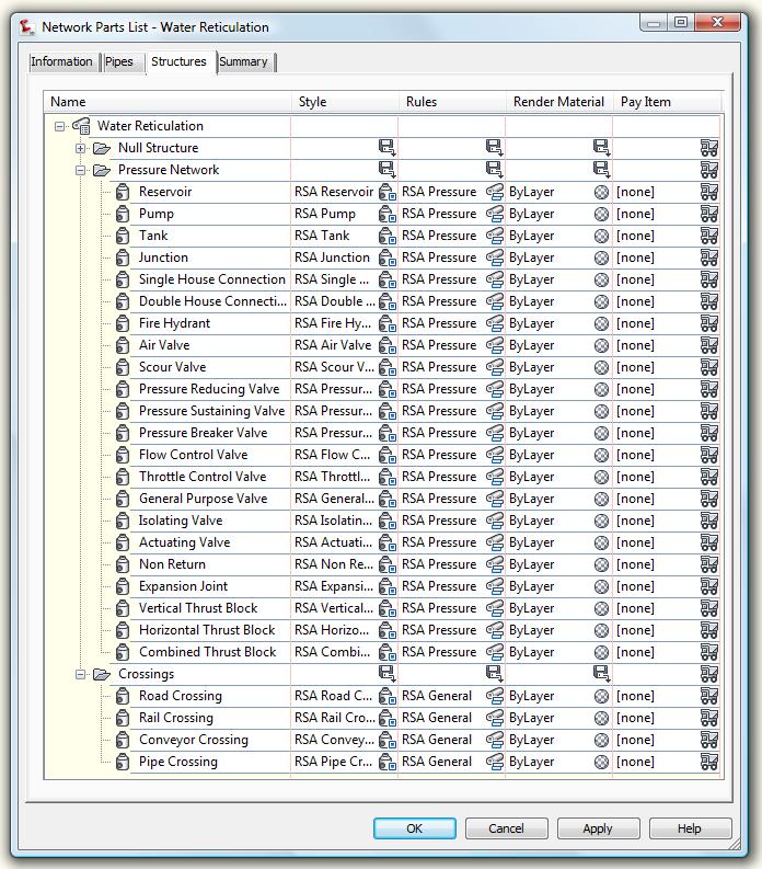
38 Sheet Size A3 5.9 Pipe Networks Parts Lists Description Screen grab / DWF / DWG Default A selection of lists for drainage and underground utilities Interference Styles Description Screen grab / DWF / DWG Default Simple Sphere Interference Shows a green sphere in 3D view Pipe Styles Description Screen grab / DWF / DWG Default Pipe Rule Set Basic Description Screen grab / DWF / DWG Default Yes
 Name")


39 Pipe Label Styles Description Screen grab / DWF / DWG Default Name Size and 2D Length (Centre to Centre) Name Only Pipe Length and Slope Pipe Table Styles Description Screen grab / DWF / DWG Default Pipe Setting Out Simple Summary Pipe List Structure Styles Description Screen grab / DWF / DWG Default Structure Rule Styles Description Screen grab / DWF / DWG Default Basic Structure Label Styles Description Screen grab / DWF / DWG Default Name Cover and Part Type


40 Data with Connected Pipes Name Only Structure Table Styles Simple Summary List Description Screen grab / DWF / DWG Default Structure Setting Out 5.10 Corridors Corridor Styles Description Screen grab / DWF / DWG Edit Regions not Shown Edit Style Shows manual overrides to corridor section to the drawing Assembly Styles Description Screen grab / DWF / DWG Basic Mass Haul Line Styles Description Screen grab / DWF / DWG Diagonal Hatch Solid Hatch Default Yes Default Default Mass Haul View Styles Description Screen grab / DWF / DWG Default


41 Clipped Grid Yes Quantity Takeoff Criteria Description Screen grab / DWF / DWG Default Footways Road Construction Road Construction Complete Road Narrow Widening Road Overlay Road Planing Two Surfaces QTO Table Styles Description Screen grab / DWF / DWG Default Total Volume Total Volume Table Material Material Volume Table 5.11 Plan and Profile Sheets View Frame Styles Description Screen grab / DWF / DWG Default Simple View Frame Label Styles Description Screen grab / DWF Default


42 Simple / DWG Match Line Styles Description Screen grab / DWF / DWG Simple ANSI 37 Hatched Masking Applys a ANSI 37 fill to mask out the next sheet Default Simple ANSI 38 Hatched Masking Applies a ANSI 38 fill to mask out the next sheet Simple No Masking Simple Solid Masking No fill Applies a white solid fill to mask out the next sheet Match Line Label Styles Match Line Left Simple Description Screen grab / DWF / DWG Default Match Line Right Simple

43 6 Pipe and Structure Catalogue The RSA Country Kit contains a number of parts for drainage and underground utilities. These are accessed from the RSA Metric Pipes and RSA Metric Structures parts catalog, which must be set first to enable their use


44 6.1 Pipes and Structures Sewer System

45 6.1.2 Stormwater System


46 6.2 Pressure Network Fittings
47
 2D Geometry: Lane")

 Using the assembly sets and")

48 7 Intersections (also known as Junctions in the UK and Ireland) 2D Geometry: Lane offsets set to 3.00m Kerb radius fillets set to 10m circular fillets 3D Geometry: Lane crossfall set to -2.5% (-1:40) Using the assembly sets and or customised sets mentioned in the previous section these can be used to automatically build the junction corridor model

49 8 Roundabouts A design standards file has been provided to give some suitable values to produce simple roundabout results. As there are no specific tables for all values these settings are to give an outline of a roundabouts to which can be edited depending on results from roundabout traffic analysis for capacity.
Design of Roundabouts using Corridor Models (Part 1 of 2)
") AUTODESK CIVIL3D Design of Roundabouts using Corridor Models (Part 1 of 2) Dynamic vertical modeling By Jack Strongitharm Civil 3D Technical Sales Manager UK and Ireland jack.strongitharm@autodesk.com
AUTODESK CIVIL3D Design of Roundabouts using Corridor Models (Part 1 of 2) Dynamic vertical modeling By Jack Strongitharm Civil 3D Technical Sales Manager UK and Ireland jack.strongitharm@autodesk.com
A selection of files of content to give the out of the box experience of a local product. Local standards in drawing production, design and reporting
 A t CAD Civil AutoCAD Ci il 3D 2011 UK and Ireland Country Kit Jack Strongitharm Application Engineer What is a Country Kit? A selection of files of content to give the out of the box experience of a local
Existing and Design Profiles
 NOTES Module 09 Existing and Design Profiles In this module, you learn how to work with profiles in AutoCAD Civil 3D. You create and modify profiles and profile views, edit profile geometry, and use styles
Exercise 1: The AutoCAD Civil 3D Environment
 Exercise 1: The AutoCAD Civil 3D Environment AutoCAD Civil 3D Interface Object Base Layer Object Component Layers 1-1 Introduction to Commercial Site Grading Plans AutoCAD Civil 3D Interface AutoCAD Civil
Module 10. Assemblies and Corridors. Objectives
 NOTES Module 10 Assemblies and Corridors In this module, you learn to work with assemblies and corridors in AutoCAD Civil 3D. Corridor models are used to represent road designs in Civil 3D. An assembly
Subdivision Cross Sections and Quantities
 NOTES Module 11 Subdivision Cross Sections and Quantities Quantity calculation and cross section generation are required elements of subdivision design projects. After the design is completed and approved
Create styles that control the display of Civil 3D objects. Copy styles from one drawing to another drawing.
 NOTES Module 03 Settings and Styles In this module, you learn about the various settings and styles that are used in AutoCAD Civil 3D. A strong understanding of these basics leads to more efficient use
Tips and Tricks. Matt Kolberg, Technology Consultant. Consulting Training Software
 Tips and Tricks Matt Kolberg, Technology Consultant Consulting Training Software Civil 3D Session Description This 60-minute session will reveal those hidden gems and other undocumented functionality in
AutoCAD Civil 3D 2009 ESSENTIALS
 AutoCAD Civil 3D 2009 ESSENTIALS SDC PUBLICATIONS Schroff Development Corporation www.schroff.com Better Textbooks. Lower Prices. Alignments and Profiles Section 2: Profiles In this section you learn how
AUTOCAD CIVIL 3D 2016
 SMALL SCALE AND MICRO IRRIGATION SUPPORT PROJECT Training Manual on AUTOCAD CIVIL 3D 2016 for irrigation professionals SMIS RPMU, Hawassa January 25-30/2017 (Prepared by Abdo Kedir) CONTENTS 1 CIVIL 3D
SurvCADDR. Section - Profile Module. File Modify Display Draw Inq-Set Pnts Profiles Design Sections Misc PRODUCT DESCRIPTION BENEFITS & ADVANTAGES
 File Modify Display Draw Inq-Set Pnts Profiles Design Sections Misc SurvCADDR Section - Profile Module PRODUCT DESCRIPTION engineeringsoftwareforanexpandinguniverse The Section - Profile Module creates
AUTOCAD CIVIL 3D 2008
 AUTOCAD CIVIL 3D 2008 AUSTRALIAN COUNTRY KIT 1 TABLE OF CONTENTS 2 Purpose of this document:... 4 3 Drafting and Plans Production Settings... 5 3.1 Sheet Creation... 5 3.2 Drafting and Labeling... 5 3.3
CADD & Civil 3D User Guidelines
 THURSTON COUNTY PUBLIC WORKS DEPARTMENT Design and Construction Division CADD & Civil 3D User Guidelines V4.0_06_10_15 1 THURSTON COUNTY PUBLIC WORKS DEPARTMENT DESIGN AND CONSTRUCTION DIVISION CADD &
How to Design and Submit a DOT Project with Civil 3D
 11/30/2006-5:00 pm - 6:30 pm Room:San Polo - 3503 (ISD Campus) How to Design and Submit a DOT Project with Civil 3D Seth Cohen - ProSoft NET CV35-2 This lab will delve into the workflows and processes
Tutorial Guide to AutoCAD 2015
 Tutorial Guide to AutoCAD 2015 2D Drawing, 3D Modeling Shawna Lockhart SDC P U B L I C AT I O N S For Microsoft Windows Better Textbooks. Lower Prices. www.sdcpublications.com Powered by TCPDF (www.tcpdf.org)
Full Contents. Essentials, Workbook
 Section 1: Overview Essentials 1.1 Introduction... 3 Learning InRoads... 3 Basic Rules... 3 How to Use This Guide... 4 Section Breakdown... 5 Section 1: Overview Essentials... 5 Section 2: Production Essentials...
Full Contents. InRoads Essentials
 Section 1: Overview Essentials 1.1 Introduction... 3 Learning InRoads... 3 Basic Rules... 3 How to Use This Guide... 4 Section Breakdown... 5 Section 1: Overview Essentials... 5 Section 2: Production Essentials...
Mastering AutoCAD 2D
 Course description: Mastering AutoCAD 2D Design and shape the world around you with the powerful, flexible features found in AutoCAD software, one of the world s leading 2D design applications. With robust
An Introduction to Dimensioning Dimension Elements-
 An Introduction to Dimensioning A precise drawing plotted to scale often does not convey enough information for builders to construct your design. Usually you add annotation showing object measurements
SCHEDULE 10 ENGINEERING DRAWING SUBMISSION
 SCHEDULE 10 ENGINEERING DRAWING SUBMISSION Subdivision, Development and Servicing Bylaw No. 1535 10. ENGINEERING DRAWING SUBMISSIONS TABLE OF CONTENTS 1.0 General 3 1.1. Introduction 3 1.2. General Requirements
COPYRIGHTED MATERIAL. The Interface
 Chapter 1 The Basics If you want to be a master in anything, you have to start with the basics. Since the Autodesk AutoCAD Civil 3D platform has evolved so much over the years, now more than ever you have
Chapter 6 Title Blocks
 Chapter 6 Title Blocks In previous exercises, every drawing started by creating a number of layers. This is time consuming and unnecessary. In this exercise, we will start a drawing by defining layers
Corridors. To create a corridor you must have an alignment (baseline), a profile (existing or proposed), and an assembly.
, a profile (existing or proposed), and an assembly.") Corridors To create a corridor you must have an alignment (baseline), a profile (existing or proposed), and an assembly. Alignments You have 2 choices in defining an alignment: (1) Alignments > Create
Corridors To create a corridor you must have an alignment (baseline), a profile (existing or proposed), and an assembly. Alignments You have 2 choices in defining an alignment: (1) Alignments > Create
Corridors To create a corridor you must have an alignment (baseline), a profile (existing or proposed), and an assembly.
, a profile (existing or proposed), and an assembly.") Corridors 2018-2019 To create a corridor you must have an alignment (baseline), a profile (existing or proposed), and an assembly. Alignments You have 2 choices in defining an alignment from scratch: (1)
Corridors 2018-2019 To create a corridor you must have an alignment (baseline), a profile (existing or proposed), and an assembly. Alignments You have 2 choices in defining an alignment from scratch: (1)
Tutorial Guide to AutoCAD 2014
 Tutorial Guide to AutoCAD 2014 2D Drawing, 3D Modeling Shawna Lockhart SDC P U B L I C AT I O N S For Microsoft Windows Better Textbooks. Lower Prices. www.sdcpublications.com Visit the following websites
Tutorial Guide to AutoCAD 2013
 Tutorial Guide to AutoCAD 2013 2D Drawing, 3D Modeling Shawna Lockhart SDC P U B L I C AT I O N S Schroff Development Corporation For Microsoft Windows Better Textbooks. Lower Prices. www.sdcpublications.com
CITY OF BEVERLY HILLS Department of Public Works and Transportation Civil Engineering Division STREET/ALLEY IMPROVEMENT PLAN REVIEW CHECKLIST
 CITY OF BEVERLY HILLS Department of Public Works and Transportation Civil ing Division STREET/ALLEY IMPROVEMENT PLAN REVIEW CHECKLIST The following checklist consists of the minimum requirements for preparation
Plan Preparation Checklist
 Appendix D Plan Preparation Checklist It is the responsibility of the Designer to complete and submit this checklist along with all required drawings for OUC (EFP) Review. All drawings submitted for OUC
Survey Data and TOPO Checklist
 Checklists Survey Data and TOPO Preliminary Plan Field Review Plans o Field Review Erosion Control Right-of-Way and Utility Meeting Plans Final Plan Field Review Plans Methods of Plan Markups Plan-in-Hand
BASIC TERMS OF ROAD GEOMETRY
 BASIC TERMS OF ROAD GEOMETRY Contour line = a line, which connects terrain points of the same elevation Contour line interval (equidistance) = elevation difference between contour lines Line of maximum
Developments in BIM Infrastructure Design. Barry Blake 3 rd June 2014
 Developments in BIM Infrastructure Design Barry Blake 3 rd June 2014 BIM Infrastructure Design BIM Collaboration / Sharing / Design validation / Integrating various elements of design What are we delivering
Autodesk Advance Steel. Drawing Style Manager s guide
 Autodesk Advance Steel Drawing Style Manager s guide TABLE OF CONTENTS Chapter 1 Introduction... 5 Details and Detail Views... 6 Drawing Styles... 6 Drawing Style Manager... 8 Accessing the Drawing Style
Montana Association of Registered Land Surveyors Conference 2013
 AutoCAD CIVIL 3D Survey Features - Field to Finish This session is an introduction to the Civil 3D Survey Tools. We will cover some basics of working with Survey Databases and Automated Linework. We will
AutoCAD Civil 3D Fundamentals
 AutoCAD Civil 3D Fundamentals Course Length: 4 days The AutoCAD Civil 3D Fundamentals training course is designed for Civil Engineers and Surveyors who want to take advantage of the AutoCAD Civil 3D software
06/17/02 Page 1 of 12
 Understanding the Graphical User Interface When you start AutoCAD, the AutoCAD window opens. The window is your design work space. It contains elements that you use to create your designs and to receive
LD20558-L Parking Lots with AutoCAD Civil 3D Corridors
 LD20558-L Parking Lots with AutoCAD Civil 3D Corridors Steven Hill CAD Manager, Civil Designer / Geosyntec Consultants.NET Application Developer / Red Transit Consultants, LLC Learning Objectives Discover
RRR Design & Modeling with the FDOT Civil 3D State Kit
 RRR Design & Modeling with the FDOT Civil 3D State Kit Mike Racca - CADD Applications Development Specialist Production Support Office CADD 605 Suwannee St - MS 40, Tallahassee, Florida 32399 Session Objectives:
n 4ce Professional Module
 n 4ce Fact Sheet n 4ce Professional Module For the discerning user with specialist needs, n 4ce Professional provides extra facilities in Design and 3D presentations. Using the same platform as Lite, extra
COURSE: INTRODUCTION TO CAD GRADES: UNIT: Measurement
 UNIT: Measurement - Students will demonstrate correctness in measuring using various scales and instruments. Demonstrate the various marks that make up a ruler including 1/16, 1/8, ¼ and ½. Assessment
1: INTRODUCTION TO AUTOCAD
 AutoCAD syllabus 1: INTRODUCTION TO AUTOCAD Starting AutoCAD AutoCAD Screen Components Drawing Area Command Window Navigation bar Status bar Invoking Commands in AutoCAD Keyboard Ribbon Application Menu
GeoTools commands summary
 GeoTools commands summary The following list of command descriptions show what each one of the GeoTools commands do. All commands shown here work in AutoCAD as well as Bricscad unless otherwise noted.
Inserting and Creating ImagesChapter1:
 Inserting and Creating ImagesChapter1: Chapter 1 In this chapter, you learn to work with raster images, including inserting and managing existing images and creating new ones. By scanning paper drawings
Advance Steel. Drawing Style Manager s guide
 Advance Steel Drawing Style Manager s guide TABLE OF CONTENTS Chapter 1 Introduction...7 Details and Detail Views...8 Drawing Styles...8 Drawing Style Manager...9 Accessing the Drawing Style Manager...9
Create all plan and profile sheets in the current drawing. Create all plan and profile sheets in individual drawings.
 NOTES Module 18 Roadway Plan Production In this module, you learn how to work with Roadway Plan Production tools in AutoCAD Civil 3D. The Plan Production tools are used to automate the generation of plan
AutoCAD 2D I. Module 16. Isometric and Dimensioning. IAT Curriculum Unit PREPARED BY. January 2011
 AutoCAD 2D I Module 16 Isometric and Dimensioning PREPARED BY IAT Curriculum Unit January 2011 Institute of Applied Technology, 2011 Module 16 Auto CAD Self-paced Learning Modules AutoCAD 2D Isometric
Introduction to Autodesk Inventor for F1 in Schools (Australian Version)
") Introduction to Autodesk Inventor for F1 in Schools (Australian Version) F1 in Schools race car In this course you will be introduced to Autodesk Inventor, which is the centerpiece of Autodesk s Digital
Introduction to Autodesk Inventor for F1 in Schools (Australian Version) F1 in Schools race car In this course you will be introduced to Autodesk Inventor, which is the centerpiece of Autodesk s Digital
COPYRIGHTED MATERIAL. Welcome to the Civil 3D Environment
 Welcome to the Civil 3D Environment Chapter 1 To paraphrase, Civil 3D isn t your father s AutoCAD. If you re just getting into the Civil 3D environment, want to learn how to get around in models, and would
Dean Muccio AutoCAD Interior Designer. for the. AutoCAD for Mac and PC SDC. Better Textbooks. Lower Prices.
 Dean Muccio AutoCAD 2020 for the Interior Designer AutoCAD for Mac and PC SDC P U B L I C AT I O N S Better Textbooks. Lower Prices. www.sdcpublications.com Powered by TCPDF (www.tcpdf.org) Visit the following
Type A. BWSC CAD Standards for Site Plans (Design and As-Built) Format. Scale. Fonts, Linetypes, Shapes
 Format. Scale. Fonts, Linetypes, Shapes") BWSC CAD Standards for Site Plans (Design and As-Built) Type A The following CAD standards are for Type A application and involve no work in Public Street, except for connection(s) to the Boston Water
BWSC CAD Standards for Site Plans (Design and As-Built) Type A The following CAD standards are for Type A application and involve no work in Public Street, except for connection(s) to the Boston Water
Dean Muccio. AutoCAD 2018 for the. Interior Designer. AutoCAD for Mac and PC SDC. Better Textbooks. Lower Prices.
 Dean Muccio AutoCAD 2018 for the Interior Designer AutoCAD for Mac and PC SDC P U B L I C AT I O N S Better Textbooks. Lower Prices. www.sdcpublications.com Powered by TCPDF (www.tcpdf.org) Visit the following
Using Layers and Object Properties
 Using Layers and Object Properties In This Chapter 10 Layers are like transparent overlays on which you organize and group different kinds of drawing information. The objects you create have common properties
Autodesk Map from A to Z
 Autodesk Map from A to Z Brian Glidden Course ID: GI11-2 Course outline: 3.5-Hour Tutorial (beginners) Related Class Project Environment of Autodesk Map (GI23-2L) Intermediate Lab Wednesday 4:00 P.M. -
What is a Survey? The site plan is usually based on an professional land survey.
 Site Plan: Illustrates the existing natural and built features of a site and describes proposed construction in relation to the existing features. The site plan is essential for studying the influence
AutoCAD Architecture 2018 Fundamentals
 Elise Moss Autodesk AutoCAD Architecture 2018 Fundamentals SDC P U B L I C AT I O N S Better Textbooks. Lower Prices. www.sdcpublications.com Powered by TCPDF (www.tcpdf.org) Visit the following websites
80 ` AutoCAD 2D I. Module 7. Drawing Lines Using Polar Coordinates PREPARED BY. IAT Curriculum Unit. February 2011
 80 ` AutoCAD 2D I Module 7 Drawing Lines Using Polar Coordinates PREPARED BY IAT Curriculum Unit February 2011 Institute of Applied Technology, 2011 Module 7 Auto CAD Self-paced Learning Modules AutoCAD
Harnessing AutoCAD Civil 3D 2011
 ? Harnessing AutoCAD Civil 3D 2011 ? Harnessing AutoCAD Civil 3D 2011 PHILLIP J. ZIMMERMAN Australia Brazil Japan Korea Mexico Singapore Spain United Kingdom United States Harnessing AutoCAD Civil 3D
State of Florida Department of Transportation. FDOT Traffic Plans. Signing & Pavement Markings (CE ) Signalization (CE ) Lighting
 Signalization (CE ) Lighting") State of Florida Department of Transportation FDOT Traffic Plans Signing & Pavement Markings (CE-11-0117) Signalization (CE-11-0119) Lighting (CE-11-0118) User Training Manual October 2017 PRODUCTION SUPPORT
State of Florida Department of Transportation FDOT Traffic Plans Signing & Pavement Markings (CE-11-0117) Signalization (CE-11-0119) Lighting (CE-11-0118) User Training Manual October 2017 PRODUCTION SUPPORT
Project Workbook. Stantly. AutoCAD. Civil 3D Introduction to Commercial Site Grading Plans Autodesk Authorized Training Courseware (AATC)
") AutoCAD Stantly Project Workbook Civil 3D 2008 Introduction to Commercial Site Grading Plans Autodesk Authorized Training Courseware (AATC) 23705-050008-1740A October 2007 About this Workbook This book
AutoCAD Stantly Project Workbook Civil 3D 2008 Introduction to Commercial Site Grading Plans Autodesk Authorized Training Courseware (AATC) 23705-050008-1740A October 2007 About this Workbook This book
AutoCAD Standards University of California, Santa Cruz Physical Planning & Construction
 University of California, Santa Cruz Physical Planning & Construction 1. General Requirements: 1.1 Format 1.2 Ownership 2. Required Data: 2.1 Area Tabulation 2.2 Drawing Files 2.3 External References 2.4
Making a Drawing Template
 C h a p t e r 8 Addendum: Metric Making a Drawing Template In this chapter, you will learn the following to World Class standards: 1. Starting from Scratch 2. Creating New Layers in an progecad Drawing
Making an Architectural Drawing Template
 C h a p t e r 8 Addendum: Architectural Making an Architectural Drawing Template In this chapter, you will learn the following to World Class standards:! Starting from Scratch for the Last time! Creating
Introduction To Computer-Aided Boat Design (CAD)
") LESSON THIRTY Introduction To Computer-Aided Boat Design (CAD) Lesson Overview and Objectives: This lesson is intended to introduce students to the hardware and software that is need to perform computer-aided
LESSON THIRTY Introduction To Computer-Aided Boat Design (CAD) Lesson Overview and Objectives: This lesson is intended to introduce students to the hardware and software that is need to perform computer-aided
Rhinoceros modeling tools for designers. Using Layouts in Rhino 5
 Rhinoceros modeling tools for designers Using Layouts in Rhino 5 RH50-TM-LAY-Apr-2014 Rhinoceros v5.0, Layouts, Training Manual Revised April 8, 2014, Mary Fugier mary@mcneel.com Q&A April 8, 2014, Lambertus
Completed project drawing (dimensions added for reference)
") CHAPTER 5 Fundamentals IV PROJECT EXERCISE This project exercise provides point-by-point instructions for setting up the drawing with layers and then creating the objects shown in the accompanying figure.
CHAPTER 5 Fundamentals IV PROJECT EXERCISE This project exercise provides point-by-point instructions for setting up the drawing with layers and then creating the objects shown in the accompanying figure.
Required Materials For complete material(s) information, refer to
 information, refer to") Butler Community College Science, Technology, Engineering, and Math Division Brett Trimpe Revised Spring 2016 Implemented Fall 2016 COURSE OUTLINE AutoCAD Basics Course Description EN 107. AutoCAD Basics.
Butler Community College Science, Technology, Engineering, and Math Division Brett Trimpe Revised Spring 2016 Implemented Fall 2016 COURSE OUTLINE AutoCAD Basics Course Description EN 107. AutoCAD Basics.
City of Kitchener Infrastructure Services Department Engineering Services Division. CAD Standards for Engineering
 City of Kitchener Infrastructure Services Department Engineering Services Division CAD Standards for Engineering Printed: October 29, 2012 Revision History Revision Description Date Layer revisions. June
84 part video tutorial training course. The course is 100% free with no catches or exclusions. You don
 Please Note: If you're new to Revit, you may be interested in my " Beginner's Guide to Revit Architecture " 84 part video tutorial training course. The course is 100% free with no catches or exclusions.
Triangulate This! Under the Hood on Surfaces and Grading
 Triangulate This! Under the Hood on Surfaces and Grading Dana Probert, P.E. Autodesk, Inc. CI6640-P This class will teach you the details on how AutoCAD Civil 3D builds surfaces from point clouds, points,
A Practical Guide to Carlson Software Fundamentals 2015 Rick Ellis Douglas L. Aaberg, PLS Duke Gardner
 A Practical Guide to Carlson Software Fundamentals 2015 Rick Ellis Douglas L. Aaberg, PLS Duke Gardner A Cadapult Press Publication Copyright Copyright Cadapult Press, Inc. 2015 All rights reserved. No
User Guide V10 SP1 Addendum
 Alibre Design User Guide V10 SP1 Addendum Copyrights Information in this document is subject to change without notice. The software described in this document is furnished under a license agreement or
A Practical Guide to Carlson Software Fundamentals 2018 Rick Ellis Douglas L. Aaberg, PLS Duke Gardner
 A Practical Guide to Carlson Software Fundamentals 2018 Rick Ellis Douglas L. Aaberg, PLS Duke Gardner A CADapult Press Publication Copyright Copyright CADapult Press, Inc. 2017 All rights reserved. No
1Getting set up to start this exercise
 AutoCAD Architectural DesktopTM 2.0 - Development Guide EXERCISE 1 Creating a Foundation Plan and getting an overview of how this program functions. Contents: Getting set up to start this exercise ----
Las Vegas, Nevada November 27-30, 2001
 Las Vegas, Nevada November 27-30, 2001 Speaker Name: Phil Leverault Course Title: Conquering Dimensions Course ID: Course Outline: Factors to Consider for Dimension Styles Discipline Mechanical Dimensioning
SETTING UP YOUR PAGE LAYOUT:
 In this workshop we will look at: Setting up your drawing sheet Viewports Printing your work Once you ve drawn your work in the Model space and you re ready to print, you need to set up your Drawing Sheet
Project Name: County File No.: Checked by: For: Date:
 Project Name: County File No.: Checked by: For: Date: Print name Firm or agency Items noted in the checklist shall be considered the minimum amount of information necessary for submission of construction
GEOPAK V8i SELECTseries 1, Road 2
 GEOPAK V8i SELECTseries 1, Road 2 Ohio Department of Transportation October, 2012 Ohio Department of Transportation GEOPAK Road Training Guide for MicroStation V8i SELECTseries 1, October, 2012 The information
Autodesk Architectural Desktop Functionality for the Autodesk Building Systems User
 11/28/2005-1:00 pm - 2:30 pm Room:N. Hemispheres (Salon A1) (Dolphin) Walt Disney World Swan and Dolphin Resort Orlando, Florida Autodesk Architectural Desktop Functionality for the Autodesk Building Systems
Table of contents. User interface 1: Customizable tool palette... 6 User interface 2: General GUI improvements... 7
 Table of contents WELCOME TO ADVANCE CONCRETE 2014... 5 USER INTERFACE ENHANCEMENTS... 6 User interface 1: Customizable tool palette... 6 User interface 2: General GUI improvements... 7 MODELING... 10
Assignment 13 CAD Mechanical Part 2
 Assignment 13 CAD Mechanical Part 2 Objectives In this assignment you will learn to apply the hatch and break commands along with commands previously learned. General Instructions Hatching 1. When AutoCAD's
Making an Architectural Drawing Template
 C h a p t e r 8 Addendum: Architectural Making an Architectural Drawing Template In this chapter, you will learn the following to World Class standards: 1. Starting from Scratch 2. Creating New Layers
After completing this lesson, you will be able to:
 LEARNING OBJECTIVES After completing this lesson, you will be able to: 1. Create a Circle using 6 different methods. 2. Create a Rectangle with width, chamfers, fillets and rotation. 3. Set Grids and Increment
Using Dynamic Views. Module Overview. Module Prerequisites. Module Objectives
 Using Dynamic Views Module Overview The term dynamic views refers to a method of composing drawings that is a new approach to managing projects. Dynamic views can help you to: automate sheet creation;
ESSENTIALS. Munir M. Hamad Autodesk Approved Instructor
 AUTOCAD 2010 ESSENTIALS Munir M. Hamad Autodesk Approved Instructor 76299_FMxx_FINAL.indd i 6/1/09 11:00:49 AM World Headquarters Jones and Bartlett Publishers 40 Tall Pine Drive Sudbury, MA 01776 978-443-5000
Minimum Drawing & Electronic Submittal Requirements For Record Drawings /As-Builts
 Minimum Drawing & Electronic Submittal Requirements For Record Drawings /As-Builts PUBLIC WORKS ENGINEERING DEPARTMENT Revised: February 1, 2017 MINIMUM DRAWING REQUIREMENTS A. GENERAL PLAN REQUIREMENTS:
SolidWorks 95 User s Guide
 SolidWorks 95 User s Guide Disclaimer: The following User Guide was extracted from SolidWorks 95 Help files and was not originally distributed in this format. All content 1995, SolidWorks Corporation Contents
SD DEPARTMENT OF TRANSPORTATION OFFICE OF ROAD DESIGN
 SD DEPARTMENT OF TRANSPORTATION OFFICE OF ROAD DESIGN CADD Procedures Manual Section B - Design 1 Table of Contents InRoads Master Workflow... 3 Getting Started... 3 Open InRoads Files... 3 Create and
Record Drawing Standards for Projects Version 2.1
 for Projects Version 2.1 Updated September 21, 2016 Department: Spatial Data Group Engineering & Maintenance 1. INTRODUCTION... 1 2. GENERAL STANDARDS... 1 2.1 Drawing Standards... 1 2.2 Digital Submission
CITY OF LA MARQUE CHAPTER GRAPHIC REQUIREMENTS CONSTRUCTION PLAN AND MISCELLANEOUS REQUIREMENTS
 CITY OF LA MARQUE CHAPTER 2 -------------------------------------------- GRAPHIC REQUIREMENTS CONSTRUCTION PLAN AND MISCELLANEOUS REQUIREMENTS CHAPTER 2 ------------------------------------------------
AutoCAD LT Drawing Formats
 AutoCAD LT Section 5 AutoCAD LT Drawing Formats This section covers: 1. Layers 2. Colors 3. Linetypes 4. Units 5. Text Styles 6. Dimension Styles 7. Point Styles AutoCAD LT Introduction AutoCAD LT Drawing
Anna Gresham School of Landscape Design. CAD for Beginners. CAD 3: Using the Drawing Tools and Blocks
 Anna Gresham School of Landscape Design CAD for Beginners CAD 3: Using the Drawing Tools and Blocks Amended for DraftSight V4 October 2013 INDEX OF TOPICS for CAD 3 Pages ESnap 3-5 Essential drawing tools
OpenRoads Best Practice - Civil Cells
 OpenRoads Best Practice - Civil Cells Presented by: Ian Rosam, Director Civil Product Management, Bentley Systems, Inc. 1 WWW.BENTLEY.COM 2017 Bentley Systems, Incorporated 2017 Bentley Systems, Incorporated
Dimension Styles. EDT Chapter 18 - Basic Dimensioning Practices 1
 Dimension Styles EDT 310 - Chapter 18 - Basic Dimensioning Practices 1 Dimension Styles The appearance of dimensions is controlled by over 70 different settings. Dimension Styles are saved configurations
Introduction to AutoCAD 2012
 Page 1 Introduction to AutoCAD 2012 Alf Yarwood Answers to Multiple choice questions Chapter 1 1. The toolbar at the top of the AutoCAD 2012 window is: (a) The Draw toolbar (b) The Modify toolbar (c) The
Practice Workbook. Cross Sections: Creating, Annotating, and Volumes. SELECTseries 4 ( ) or newer
 or newer") Practice Workbook This workbook is designed for use in Live instructor-led training and for OnDemand self study. The explanations and demonstrations are provided by the instructor in the classroom, or
Practice Workbook This workbook is designed for use in Live instructor-led training and for OnDemand self study. The explanations and demonstrations are provided by the instructor in the classroom, or
Introduction to IntelliCAD 6
 Introduction to IntelliCAD 6 These notes explain the basic concepts and techniques for doing 2D line drawings, with dimensions, arranged onto sheets for printing, using the 6.4 or 6.6 versions of IntelliCAD
Chief Architect New Feature List
 SYSTEM / PERFORMANCE Chief Architect Premier X4 is available in 64 bit and 32 bit versions. The 64 bit version is more efficient in managing memory and you will see better performance on larger plan files
ACAD-BAU TUTORIAL For BricsCAD platform
 ACAD-BAU TUTORIAL WWW.ARHINOVA.SI For BricsCAD platform August 06 WORKSPACE ACAD-BAU RIBBON ACAD-BAU CONTROL BAR F ACAD-BAU PALETTES BASIC SETTINGS Use New command and open the template called ACB_International.DWT.
COPYRIGHTED MATERIAL. Getting Dirty: The Basics of Civil 3D. Chapter 1. Windows on the Model
 Chapter 1 Getting Dirty: The Basics of Civil 3D Just as with any piece of software, understanding Civil 3D s controls and operation is critical to mastering it. With its dizzying array of options and settings,
Creating and Editing Plot Style Tables
 AutoCAD and Its Applications BASICS Supplemental Material Chapter 28 Creating and Editing Plot Style Tables The plot style tables supplied with AutoCAD are appropriate for many plotting applications. Use
CONSULTANT: Wantman Group, Inc SERVICE AUTHORIZATION NO. _12-03 FOR CONSULTING SERVICES CITY PROJECT NO CONSULTANT PROJECT NO.
 EXHIBIT A CONSULTING SERVICE AUTHORIZATION DATE: CONSULTANT: Wantman Group, Inc SERVICE AUTHORIZATION NO. _12-03 FOR CONSULTING SERVICES CITY P.O. NO. CITY EXPENSE CODE CITY PROJECT NO. 14-073 CONSULTANT