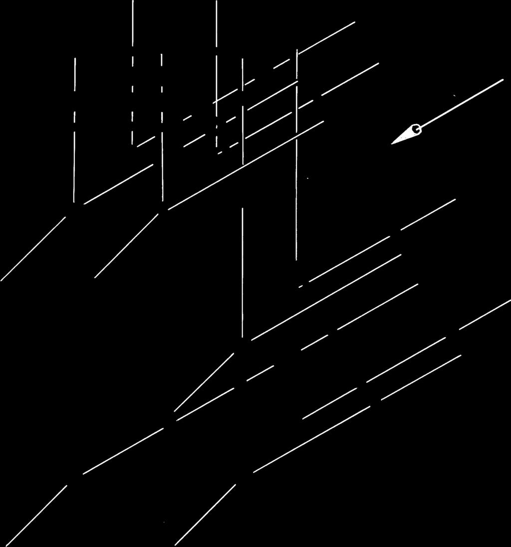
Figure 8-1 Regular Views and Auxiliary Views. 2003, Prentice-Hall, Inc. Giesecke Technical Drawing, 12e
|
|
|
- Victor Johnston
- 6 years ago
- Views:
Transcription
1 Figure 8-1 Regular Views and Auxiliary Views.


2 Figure 8-2 An Auxiliary View.
3 Figure 8-3 Drawing an Auxiliary View Folding-Line Method.
4 Figure 8-4 Drawing Parallel or Perpendicular Lines.
5 Figure 8-5 Position of the Reference Plane.
6 Figure 8-6 Drawing an Auxiliary View Reference-Plane Method.
7 Figure 8-7 Depth Auxiliary Views.
8 Figure 8-8 Height Auxiliary Views.
9 Figure 8-9 Width Auxiliary Views.
10 Figure 8-10 Revolving a Drawing.
11 Figure 8-11 Dihedral Angles.
12 Figure 8-12 Plotted Curves.
13 Figure 8-13 Reverse Construction.
14 Figure 8-14 Primary Auxiliary Views.
15 Figure 8-15 Partial Views.
16 Figure 8-16 Half Views.
17 Figure 8-17 Auxiliary Sections.
18 Figure 8-18 Auxiliary Section.
19 Figure 8-19 Auxiliary Section.
20 Figure 8-20 True Length of a Line by Means of an Auxiliary View.
21 Figure 8-21 Successive Auxiliary Views.
22 Figure 8-22 True Size of Oblique Surface Folding-Line Method.
23 Figure 8-23 True Size of Oblique Surface Reference-Plane Method.
24 Figure 8-24 Secondary Auxiliary View with Oblique Direction of Sight Given.
25 Figure 8-25 Secondary Auxiliary View Partial Views.
26 Figure 8-26 Ellipses.
27 Figure 8-27 RH Finger. Given: Front and auxiliary views. Required: Complete front, auxiliary, left-side, and top views (Layout A 3 or A4 3 adjusted).
28 Figure 8-28 V-Block. Given: Front and auxiliary views. Required: Complete front, top, and auxiliary views (Layout A 3 or A4 3 adjusted).
29 Figure 8-29 Auxiliary View Problems. Make freehand sketch or instrument drawing of selected problem as assigned. Draw given front and right-side views, and add incomplete auxiliary view, including all hidden lines (Layout A 3 or A4 3 adjusted). If assigned, design yourown right-side view consistent with given front view, and then add complete auxiliary view.
30 Figure 8-30 Anchor Bracket. Draw necessary views or partial views (Layout A 3 or A4 3 adjusted).*
31 Figure 8-31 Centering Block. Draw complete front, top, and right-side views, plus indicated auxiliary views (Layout B 3 or A3 3).*
32 Figure 8-32 Clamp Slide. Draw necessary views completely (Layout B 3 or A3 3).*
33 Figure 8-33 Guide Block. Given: Right-side and auxiliary views. Required: Right-side, auxiliary, plus front and top views all complete (Layout B 3 or A3 3).*
34 Figure 8-34 Angle Bearing. Draw necessary views, including a complete auxiliary view (Layout A 3 or A4 3 adjusted).*
35 Figure 8-35 Guide Bracket. Draw necessary views or partial views (Layout B 3 or A3 3).*
36 Figure 8-36 Rod Guide. Draw necessary views, including complete auxiliary view showing true shape of upper rounded portion (Layout B 4 or A3 4 adjusted).*
37 Figure 8-37 Brace Anchor. Draw necessary views, including partial auxiliary view showing true shape of cylindrical portion (Layout B 4 or A3 4 adjusted).*
38 Figure º Elbow. Draw necessary views, including a broken section and two half views of flanges (Layout B 4 or A3 4 adjusted).*
39 Figure 8-39 Angle Guide. Draw necessary views, including a partial auxiliary view of cylindrical recess (Layout B 4 or A3 4 adjusted).*
40 Figure 8-40 Holder Block. Draw front and right-side views (2.80 apart) and complete auxiliary view of entire object showing true shape of surface A and all hidden lines (Layout A 3 or A4 3 adjusted).*
41 Figure 8-41 Control Bracket. Draw necessary views, including partial auxiliary views and regular views (Layout C 4 or A2 4).*
42 Figure 8.42 Tool Holder Slide. Draw given views, and add complete auxiliary view showing true curvature of slot on bottom (Layout B 4 or A3 4 adjusted).*
43 Figure 8-43 Adjuster Block. Draw necessary views, including complete auxiliary view showing true shape of inclined surface (Layout B 4 or A3 4 adjusted).*
44 Figure 8-44 Guide Bearing. Draw necessary views and partial views, including two partial auxiliary views (Layout C 4 or A2 4).*
45 Figure 8-45 Drill Press Bracket. Draw given views and add complete auxiliary view showing true shape of inclined face (Layout B 4 or A3 4 adjusted).*
46 Figure 8-46 Brake Control Lever. Draw necessary views and partial views (Layout B 4 or A3 4 adjusted).*
47 Figure 8-47 Shifter Fork. Draw necessary views, including partial auxiliary view showing true shape of inclined arm (Layout B 4 or A3 4 adjusted).*
48 Figure 8-48 Cam Bracket. Draw necessary views or partial views as needed. (Layout B 4 or A3 4 adjusted).*
49 Figure 8-49 RH Tool Holder. Draw necessary views, including partial auxiliary views showing 105º angle and square hole true size. (Layout B 4 or A3 4 adjusted).*
50 Figure 8-50 Draw secondary auxiliary views, complete, which (except Prob. 2) will show the true sizes of the inclined surfaces. In Prob. 2 draw secondary auxiliary view as seen in direction of arrow (Layout B 3 or A3 3).*
51 Figure 8-51 Control Bracket. Draw necessary views including primary and secondary auxiliary views so that the latter shows true shape of oblique surface A (Layout B 4 or A3 4 adjusted).*
52 Figure 8-52 Holder Block. Draw given views and primary and secondary auxiliary views so that the latter shows true shape of oblique surface (Layout B 4 or A3 4 adjusted).*
53 Figure 8-53 Dovetail Slide. Draw complete given views and auxiliary views, including view showing true size of surface (Layout B 4 or A3 4 adjusted).*
54 Figure 8-54 Dovetail Guide. Draw given views plus complete auxiliary views as indicated (Layout B 4 or A3 4 adjusted).*
55 Figure 8-55 Adjustable Stop. Draw complete front and auxiliary views plus partial right-side view. Show all hidden lines (Layout C 4 or A2 4).*
56 Figure 8-56 Tool Holder. Draw complete front view, and primary and secondary auxiliary views as indicated (Layout B 4 or A3 4 adjusted).*
57 Figure 8-57 Box Tool Holder for Turret Lathe. Given: Front and right-side views. Required: Front and left-side views, and complete auxiliary view as indicated by arrow (Layout C 4 or A2 4).*
58 Figure 8-58 Pointing Tool Holder for Automatic Screw Machine. Given: Front and right-side views. Required: Front view and three partial auxiliary views (Layout C 4 or A2 4).*
59 5.50 R 1.00 R 1.25 Ø xR.875 2xØ.875 Figure 8-59 Print Roller. Given: Right-side view. Design your own front and auxiliary view (Use Layout A 3 or A4 3 adjusted). If assigned, use CAD to create a partial auxiliary view.
60 2.5 2X :.68 THRU FRONT VIEW.38 R.75 TYP. Figure 8-60 Clamp. Draw all required views. Include at least one auxiliary view (Layout A-3 or A4-3 adjusted).*
61 :60 : RIO - 2 PLACES R5 TYP Figure 8-61 Plastic Spacer. Draw all necessary views. Make at least one auxiliary view (Layout A-3 or A4-3 adjusted).*
62 :44 :30,THRU RIO (22) METRIC RIO(TYP.) Figure 8-62 Plastic Spacer. Draw all necessary views. Include at least one auxiliary view (Layout A-3 or A4-3 adjusted).* 8.63 Plastic Slide. Draw all required views. Include at least one
63 FRONT VIEW Figure 8-63 Plastic Slide. Draw all required views. Include at least one auxiliary view (Layout A-3 or A4-3 adjusted).*
64 :.62THRU R.62 (2.43) R.28 R.50 R R FRONT VIEW Figure 8-64 Mounting Clip. Draw all required views. Include at least one auxiliary view (Layout A-3 or A4-3 adjusted).*
Auxiliary view KCEC1101
 Auxiliary view KCEC1101 Introduction There are times when one of the six principal views will not completely describe an object. This is especially true when there are inclined or oblique planes or features
AUXILIARY VIEWS C H A P T E R N I N E
 AUXILIARY VIEWS C H A P T E R N I N E Giesecke, Hill, Spencer, Dygdon, Novak, Lockhart, Goodman 1 OBJECTIVES 1. Create an auxiliary view from orthographic views. 2. Draw folding lines or reference-plane
A Concise Introduction to Engineering Graphics
 Concise Introduction to Engineering Graphics ourth Edition Including Worksheet Series imothy J. Sexton, Professor Department of Industrial echnology Ohio University ONUS ook on CD: ECHNICL GRPHICS Meyers,
Multiviews and Auxiliary Views
 Multiviews and Auxiliary Views Multiviews and Auxiliary Views Objectives Explain orthographic and multiview projection. Identifying the six principal views. Apply standard line practices to multiviews
Study Unit. Auxiliary Views. This sneak preview of your study material has been prepared in advance of the book's actual online release.
 Study Unit Auxiliary Views This sneak preview of your study material has been prepared in advance of the book's actual online release. iii Preview You re entering now into another subject area in your
ENGR 1182 Exam 1 First Mid Term Exam Study Guide and Practice Problems
 Spring Semester 2016 ENGR 1182 Exam 1 First Mid Term Exam Study Guide and Practice Problems Disclaimer Problems in this study guide resemble problems relating mainly to the pertinent homework assignments.
Mechanical Drawing. Unit 2 Study Guide for Chapters 6-10
 Mechanical Drawing Unit 2 Study Guide for Chapters 6-10 Chapter 6 Multiview Drawing Section 6.1 Understanding Orthographic Projection A. Technical Drawing: How can a technical drawing give more accurate
Chapter Tests and Problems
 Chapter Tests and Problems Chapter 9 Auxiliary Views Test INSTRUCTIONS Answer the questions with short, complete statements or drawings as needed. QUESTIONS 1. Describe the purpose of auxiliary views.
Copyrighted Material. Copyrighted Material. Copyrighted. Copyrighted. Material
 Engineering Graphics ORTHOGRAPHIC PROJECTION People who work with drawings develop the ability to look at lines on paper or on a computer screen and "see" the shapes of the objects the lines represent.
Unit4 31. UnitS 39. Unit 6 47
 Preface..................... xi About the Author......... xiii Acknowledgments... xiv Unit 1 1 Bases for Interpreting Drawings........ I Visible Lines............. 3 Lettering on Drawings... 3 Sketching...
ENGINEERING GRAPHICS
 ENGINEERING GRAPHICS Time allowed : 3 hours Maximum Marks : 70 Note : (ii) Attempt all the questions. Use both sides of the drawing sheet, if necessary. (iii) All dimensions are in millimetres. (iv) Missing
Mechanical Engineering Drawing
 Mechanical Engineering Drawing MECH 211 LECTURE 3 Contents of the lecture Shape description Shape generation Sectional views Auxiliary views Shape description Geometric shapes are seen according to view
Downloaded from ENGINEERING DRAWING. Time allowed : 3 hours Maximum Marks : 70
 ENGINEERING DRAWING Time allowed : 3 hours Maximum Marks : 70 Note : (i) (ii) Attempt all the questions. Use both sides of the drawing sheet, if necessary. (iii) All dimensions are in millimeters. (iv)
A Concise Introduction to Engineering Graphics
 A Concise Introduction to Engineering Graphics Fourth Edition Including Worksheet Series A Timothy J. Sexton, Professor Department of Industrial Technology Ohio University BONUS Book on CD: TECHNICAL GRAPHICS
Engineering Graphics, Class 8 Orthographic Projection. Mohammad I. Kilani. Mechanical Engineering Department University of Jordan
 Engineering Graphics, Class 8 Orthographic Projection Mohammad I. Kilani Mechanical Engineering Department University of Jordan Multi view drawings Multi view drawings provide accurate shape descriptions
ORDINARY LEVEL PAST PAPERS
 ORDINARY LEVEL PAST PAPERS UNEB S4 1982 SECTION I PLANE GEOMETRY 1. (a) Construct a diagonal scale of 40mm to 10mm to read up to 20mm by 0.02mm. (b) Indicate on your scale the following readings. (i) 14.8mm.
Assembly Instructions 10 X 10 Aluminum Roof Support
 Assembly Instructions 10 X 10 Aluminum Roof Support Aluminum Roof Support Bolt Package 16-5/16 X 2 ¼ SS Bolt 24-5/16 X 1 SS Bolt 40-5/16 SS Nylon Lock Nuts 16-5/16 SS Flat Washers 28-4 ½ Wood Screws 36-1
Principles and Practice
 Principles and Practice An Integrated Approach to Engineering Graphics and AutoCAD 2016 Randy H. Shih SDC PUBLICATIONS Better Textbooks. Lower Prices. www.sdcpublications.com Powered by TCPDF (www.tcpdf.org)
ENGR 1182 Midterm Exam 1: Study Guide and Practice Problems
 ENGR 1182 Midterm Exam 1: Study Guide and Practice Problems Disclaimer Problems seen in this study guide may resemble problems relating mainly to the pertinent homework assignments. Reading this study
CATALOG OF REPLACEMENT PARTS
 CATALOG OF REPLACEMENT PARTS MODEL X13 SERIES SLICER FORM 43180 Rev. A (April 2013) F-43180 Rev. A (April 2013) - 2-2013 Table of Contents 5 ELECTRICAL COMPONENTS 7 RING GUARD AND CENTER PLATE 9 ARM ASSEMBLY
PROJECTIONS PARALLEL CONICAL PROJECTIONS PROJECTIONS OBLIQUE ORTHOGRAPHIC PROJECTIONS PROJECTIONS
 PROJECTIONS CONICAL PROJECTIONS PARALLEL PROJECTIONS OBLIQUE PROJECTIONS ORTHOGRAPHIC PROJECTIONS ISOMETRIC MULTI-VIEW an object; The Description of Forms Behind every drawing of an object is space relationship
Typical 250 Series Center Drive Conveyor Configuration...3. Typical 250 Series End Drive Conveyor Configuration...4
 Table of Contents Typical 250 Series Center Drive Conveyor Configuration...3 Typical 250 Series End Drive Conveyor Configuration...4 Fixed Side Rails 250-0153-LLL, 250-0170-LLL, 250-0174-LLL, 250-0178-LLL,
INSTALLATION INSTRUCTIONS
 PARTS LIST ITEM PART DESCRIPTION QTY 73-A 503F 9MM 50G 5A 50E 505S 50H Connector Bracket Door Stops Support Bar Panel Glass Bracket Wall Mount Bracket Rollers Center Guide Recessed Finger Pull Fixed Panel
Design & Communication Graphics Higher Level Section A (60 marks)
") 1 L.85A Pre-Leaving Certificate Examination, 2012 Design & Communication Graphics Higher Level Section A (60 marks) Time: 3 Hours This examination is divided into three sections: SECTION A SECTION B SECTION
1 L.85A Pre-Leaving Certificate Examination, 2012 Design & Communication Graphics Higher Level Section A (60 marks) Time: 3 Hours This examination is divided into three sections: SECTION A SECTION B SECTION
Training Guide Basics
 Training Guide Basics 2014, Missler Software. 7, Rue du Bois Sauvage F-91055 Evry, FRANCE Web: www.topsolid.com E-mail: info@topsolid.com All rights reserved. TopSolid Design Basics This information is
Principles and Practice:
 Principles and Practice: An Integrated Approach to Engineering Graphics and AutoCAD 2014 Randy H. Shih Multimedia Disc SDC PUBLICATIONS Better Textbooks. Lower Prices. www.sdcpublications.com Video presentations
BEST PRACTICE GUIDE. Socket Bases. Working with Concrete Slabs
 Working with Concrete Slabs When working with concrete slabs the barrier protection can be erected in three ways - with socket bases, adjustable slab edge brackets and multi slab clamps. Socket Bases 1
TRAILMATE METEOR ASSEMBLY MANUAL
 TRAILMATE METEOR ASSEMBLY MANUAL The Trailmate Meteor recumbent has been designed for easy assembly. This means more time to enjoy the smooth ride with single speed, 3 speed coaster brake and 21 speed
2004 Academic Challenge
 2004 Academic Challenge ENGINEERING GRAPHICS TEST - REGIONAL Engineering Graphics Test Production Team Ryan Brown, Illinois State University Author/Team Coordinator Kevin Devine, Illinois State University
CLOTHING REQUIREMENT SkillsUSA-VICA Blazer, sweater, or windbreaker and accompanying official dress. Or appropriate professional/business attire.
 BOARD DRAFTING - MECHANICAL PURPOSE To evaluate each contestant's preparation for employment and to recognize outstanding students for excellence and professionalism in the field of machine drafting. First,
Reavis High School Curriculum Snapshot/Cover Page for Computer Aided Design (CAD)
") Reavis High School Curriculum Snapshot/Cover Page for Computer Aided Design (CAD) Unit 1: Introduction In this unit, students will identify components of a Computer Aided Design (CAD) system and how to
Reavis High School Curriculum Snapshot/Cover Page for Computer Aided Design (CAD) Unit 1: Introduction In this unit, students will identify components of a Computer Aided Design (CAD) system and how to
M2 Assembly. M2 Sub-Assemblies mm Belt Sub-Assembly mm Belt Sub-Assembly Spider Sub-Assembly... 4
 M2 Assembly Table of Contents M2 Sub-Assemblies... 3 630mm Belt Sub-Assembly... 3 702mm Belt Sub-Assembly... 3 Spider Sub-Assembly... 4 Idler Bolt Sub-Assembly... 8 Y Motor Sub-Assembly... 9 X Motor Sub-Assembly...
Marking Scheme Engineering Graphics
 Marking Scheme Engineering Graphics All Questions are to be answered correctly and accurately. General Note: (i) (ii) (iii) (iv) (v) Marks are to be awarded in proportion to the work done. Mistakes in
11/12/2015 CHAPTER 7. Axonometric Drawings (cont.) Axonometric Drawings (cont.) Isometric Projections (cont.) 1) Axonometric Drawings
 Axonometric Drawings (cont.) Isometric Projections (cont.) 1) Axonometric Drawings") CHAPTER 7 1) Axonometric Drawings 1) Introduction Isometric & Oblique Projection Axonometric projection is a parallel projection technique used to create a pictorial drawing of an object by rotating the
CHAPTER 7 1) Axonometric Drawings 1) Introduction Isometric & Oblique Projection Axonometric projection is a parallel projection technique used to create a pictorial drawing of an object by rotating the
mila-wall (Series100) General Operating Instructions page 1 of 15
 General Operating Instructions page 1 of 15") mila-wall (Series100) General Operating Instructions page 1 of 15 Step #1: Before setting up walls, lower adjustable leveling feet on each panel approximately 1". This will allow access to the threaded
mila-wall (Series100) General Operating Instructions page 1 of 15 Step #1: Before setting up walls, lower adjustable leveling feet on each panel approximately 1". This will allow access to the threaded
Beginning Engineering Graphics 3 rd Week Lecture Notes Instructor: Edward N. Locke Topic: The Coordinate System, Types of Drawings and Orthographic
 Beginning Engineering Graphics 3 rd Week Lecture Notes Instructor: Edward N. Locke Topic: The Coordinate System, Types of Drawings and Orthographic 1 st Subject: The Cartesian Coordinate System The Cartesian
INSTALLATION LOW HEADROOM EXTENSION. 1 Cutting Vertical Track. 2 Quick Install Jamb Brackets
 LOW HEADROOM EXTENSION P.O. Box 67, Mt. Hope, OH., 44660 Supplemental insert Copyright 2016 Wayne Dalton, a division of Part No. 333897 REV3 5/03/2016 This supplemental installation instruction is to be
ALDoor DOUBLE DOOR INSTALLATION
 Assembly Top Jamb Side Jamb Horizontal Vertical Vertical Jamb Brackets General Layout 15-20 mm Red (LHS) Cable Drum Red Cone Black Cone Black (RHS) Cable Drum 75 mm Minimum Left Hand Side Bearing Plate
ORTHOGRAPHIC PROJECTION
 ORTHOGRAPHIC PROJECTION C H A P T E R S I X OBJECTIVES 1. Recognize and the symbol for third-angle projection. 2. List the six principal views of projection. 3. Understand which views show depth in a drawing
2009 Academic Challenge
 2009 Academic Challenge ENGINEERING GRAPHICS TEST SECTIONAL This Test Consists of 50 Questions Engineering Graphics Test Production Team Ryan Brown, Illinois State University Author/Team Leader Kevin Devine,
technical drawing
 technical drawing school of art, design and architecture nust spring 2011 http://www.youtube.com/watch?v=q6mk9hpxwvo http://www.youtube.com/watch?v=bnu2gb7w4qs Objective abstraction - axonometric view
Onyx 90 Media Cutter. Parts Manual
 Parts Manual Professional Picture Frame Equipment 441 South Whitted Street Hendersonville, NC 28739 Thank you for purchasing the Onyx 90 Media Cutter. Please read all instructions before operating your
INSTRUCTIONS TS93 GSR PT RIGHT HAND ACTIVE LEFT HAND INACTIVE RIGHT HAND INACTIVE LEFT HAND ACTIVE
 INSTRUCTIONS ATTENTION!!! Before you begin, determine installation type (RIGHT HAND ACTIVE OR INACTIVE). Door coordinator suitable for door from 59 to 98 in width. Inactive door width in the case of unequal
Leaving Certificate 2014
 Coimisiún na Scrúduithe Stáit State Examinations Commission Leaving Certificate 2014 Marking Scheme Design and Communication Graphics Higher Level Note to teachers and students on the use of published
Model No: TC10. Parts Information: Tyre Changer - Automatic
 Page 1 of 11 1 TC10.01 BODY 2 TC10.02 COLUMN 3 TC10.03 HORIZONTAL ARM ASS'Y 4 TC10.04 WASHER 5 TC10.05 RUBBER FOOT 6 TC10.06 COVER 7 TC10.07 SCREW M14x42 8 TC10.08 PRESS COVER 9 TC10.09 STOP-UP 10 TC10.10
No. 412, 414, 416 Operations Manual
 No. 412, 414, 416 Operations Manual CARE: Occasional oiling of moving parts with machine oil will ease operation and extend the life of the brake. Occasionally check and tighten the lower beam bracket
The Derby Magic Company Track Assembly Instructions, revision D page 1 of 10
 The Derby Magic Company Track Assembly Instructions, revision D page 1 of 10 Thank you for purchasing a Derby Magic Pinewood Derby Track. To assemble your track, start with the stand. The parts of the
Compatibility overview of accessories for lathe
 Compatibility overview of accessories for lathe Accessory parts for turning Face clamping disc Ø 170 mm 3440295 Face clamping disc Ø 240 mm 3441352 Face clamping disc Ø 250 mm 3440552 Face clamping disc
Mounting Instructions Item No.: /521/522/420/421/422
 Mounting Instructions Item No.: 541.35.520/521/522/420/421/422 Revolving Corner Unit In addition to these general mounting instructions, please refer to the fitting instructions, where the individual drilling
INSTALLATION INSTRUCTIONS for the JOMY RETRACTABLE LADDER. If there are any questions, please call (800)
") INSTALLATION INSTRUCTIONS for the JOMY RETRACTABLE LADDER If there are any questions, please call (800) 255-2591 INSTALLATION INSTRUCTIONS WARNING! Ladder Sections Lock When Closed. Do Not Install or Close
INSTALLATION INSTRUCTIONS for the JOMY RETRACTABLE LADDER If there are any questions, please call (800) 255-2591 INSTALLATION INSTRUCTIONS WARNING! Ladder Sections Lock When Closed. Do Not Install or Close
MULTIPLE CHOICE QUESTIONS - CHAPTER 6
 MULTIPLE CHOICE QUESTIONS - CHAPTER 6 1. The selection of the front view in executing a multiview drawing of an object is dependent upon the following factors: a. size and shape of the object and their
Drilling. Drilling is the operation of producing circular hole in the work-piece by using a rotating cutter called DRILL.
 Drilling Drilling is the operation of producing circular hole in the work-piece by using a rotating cutter called DRILL. The machine used for drilling is called drilling machine. The drilling operation
Graphical Communication for Engineering ENSC 204 Final Exam
 Name: Student #: Graphical Communication for Engineering ENSC 204 Final Exam December 16, 2015 Time: 3 hours CLOSED BOOK EXAM Read all the instructions below. Do NOT start the exam until you are told to.
Chapter 5 Pictorial Projection
 Chapter 5 Pictorial Projection Objectives After completing this chapter, the students will be able to Create freehand sketches using the correct sketching techniques. Explainthe difference between axonometric
L182 - Installation Sheet Modular Wine Rack ( Wall Mount )
") Modular Wine Rack ( Wall Mount ) 1A 1B 2B 2A Cross Bar Options: 1A 2A 1B 2B Modular Wine Rack ( Wall Mount ) Parts Rail LED arm modules Wine bottle cross bars Rail cover Setscrew cover 1) Drill holes and
Modular Wine Rack ( Wall Mount ) 1A 1B 2B 2A Cross Bar Options: 1A 2A 1B 2B Modular Wine Rack ( Wall Mount ) Parts Rail LED arm modules Wine bottle cross bars Rail cover Setscrew cover 1) Drill holes and
KNOB LATCH. Specifications: Glass-To-Wall Installation CAT NO. LAT001 C.R. LAURENCE CO., INC. PROFESSIONAL QUALITY
 Specifications: Material: Solid brass Hole Size Required: 7/8" (22mm) Glass Thickness Range: 3/8" (10mm) to 1/2" (12mm) Includes: Knob, Tapered Strike for wall-to-glass installation and J-Hook for glass-to-glass
I 640 West. c Offi. pany Phone. c ~ g CHICAGO 6. Ill. M h:tjryant OMPOUND RING BAR SUPPORT. GilBERT C DEarbom ~.
 ll / - M h:tjryant c Offi I 640 West g CHICAGO 6. Ill pany Phone. c ~ GilBERT C DEarbom 2-5566 ~. OMPOUND TIL~:~ BORING, ~~: F:o~~:YH~~~ DRILLING ':~~~N~:E~~7:NE RECTANGULAR TAB ~~~;:E~:~z:T~~L TABLEe
vario drive turn TU 1503V The new compact lathe with electronically adjustable speed. Perfect for the model maker
 turn TU 1503V The new compact lathe with electronically adjustable speed. Perfect for the model maker DC motor Ribbed prism bed made of grey cast iron, inductively hardened and ground Hardened and ground
Door window. Front door window, assembly overview
 64-50 Door window Front door window, assembly overview 1 - Window channel Pushed onto flange 2 - Door window Removing Page 64-52 Adjusting Page 64-53 3 - Door 4 - Outer window channel Pushed onto flange
Installing Continuous Light Trap
 Installing Continuous Light Trap Warning!! Disconnect All Electrical Power Sources Before Installing Light Trap Tools Required Power Drill Level 3/8" Driver ¼" Driver 5/16" Driver Step Ladder Description
Click Here to Go Back
 Click Here to Go Back Fig. -94 Fig. -97 CC42D 10. Remove the cap screw securing the gear shift stopper plate pin retainer; then remove the retainer. Fig. -95 CC45D 12. Remove the link arm and account for
9 X 12 FIXED TYPE ALUMINUM WINDOW BARS INSTALLATION INSTRUCTIONS Import Note : 9 X 12 Spacing Fixed Type Installation is covered in this Instruction.
 Import Note : 9 X 12 Spacing Fixed Type Installation is covered in this Instruction. Fixed Bars can be Mount in Recess Position ( Between Window Jamb/ Frame )or Surface Mount (Face Of Wall) This Fixed
1822-I. Spindle Assembly. Pipe and Bolt Threading Machine. Ridge Tool Company/Elyria, Ohio, U.S.A. 2* 3 4 5* * *
 -I Pipe and Bolt Threading Machine Spindle Assembly * * * 0 * * * 0 * * 0* * * Rear Cover * Screw () * Washer () Top Cover w/clips (Includes,, ) * J Clip () Front Cover * Screw () Pivot Rod Support ()
Design & Communication Graphics
 L.84/85 Design & Communication Graphics Marking Scheme Ordinary Pg. 3 Higher Pg. 12 2013 L.84/85_MS 1/20 2013 L.84/85_MS 2/20 SECTION A - Core - Answer Any Three of the questions on this A3 sheet A-1.
OPERATOR ADAPTER SQDV
 OPERATOR ADAPTER SQDV Installation Instructions for Square D Bulletin 9422 Variable Depth Operating Mechanisms (For parts list, see Page 2) Rev. B 2018 Hoffman Enclosures Inc. PH 7634222211 nvent.com/hoffman
Cambridge International Examinations Cambridge International General Certificate of Secondary Education
 Cambridge International Examinations Cambridge International General Certificate of Secondary Education *3334648914* DESIGN AND TECHNOLOGY 0445/32 Paper 3 Resistant Materials October/November 2016 1 hour
Qwik-Fence Installation Instructions
 Qwik-Fence Installation Instructions 1 Tools Required The following installation instructions should be used as a guide for installing Folding Guard Qwik-Fence Partitions. Good common sense and appropriate
2016 Academic Challenge
 2016 Academic Challenge ENGINEERING GRAPHICS TEST REGIONAL This Test Consists of 40 Questions Engineering Graphics Test Production Team Ryan K. Brown, Illinois State University Author/Team Leader Mark
Engineering Graphics Essentials with AutoCAD 2015 Instruction
 Kirstie Plantenberg Engineering Graphics Essentials with AutoCAD 2015 Instruction Text and Video Instruction Multimedia Disc SDC P U B L I C AT I O N S Better Textbooks. Lower Prices. www.sdcpublications.com
TIME SCHEDULE. Module Topic Periods 1 Importance of Engineering Graphics Drawing Instruments Drawing Standards Lettering and Numbering
 COURSE TITLE : ENGINEERING GRAPHICS (First Semester) COURSE CODE : COURSE CATEGORY : F PERIODS/WEEK : 3 PERIODS/SEMESTER : 54 CREDITS : Examination in the Second Semester RATIONALE: Engineering Graphics
Sketching Fundamentals
 Sketching Fundamentals Learning Outcome When you complete this module you will be able to: Make basic engineering sketches of plant equipment. Learning Objectives Here is what you will be able to do when
Installation And Care Instructions. Vertical Honeycomb Shades
 Installation And Care Instructions Vertical Honeycomb Shades Rev 5/2013 Table Of Contents Getting Started... 3 Parts Overview... 4 Materials Required... 5 Tools Required... 6 Outside Mount Installation...
Installation Introduction
 Installation Guide Installation Introduction The On The Right Track system is a very versatile system, it can being installed several different ways and on various ceiling types. Here are the installation
B.E Mini Projects
 B.E Mini Projects 2017-2018 S.NO CMP001 CMP002 CMP003 CMP004 CMP005 CMP006 CMP007 CMP008 CMP009 CMP010 CMP011 CMP012 CMP013 CMP014 CMP015 CMP016 CMP017 CMP018 CMP019 CMP020 CMP021 CMP022 CMP023 CMP024
ENGINEERING GRAPHICS ESSENTIALS
 ENGINEERING GRAPHICS ESSENTIALS with AutoCAD 2012 Instruction Introduction to AutoCAD Engineering Graphics Principles Hand Sketching Text and Independent Learning CD Independent Learning CD: A Comprehensive
INSTRUCTIONS and PARTS BOOK. U. S. Blind Stitch Machines
 r- INSTRUCTIONS and PARTS BOOK for U. S. Blind Stitch Machines Model 88-R. S. BLIND STITCH MACHINE CORP. 12 SEVENTH AVENUE NEW YORK 1, N. Y. LAclcawanna 4-9144-5-6 A SUPPLEMENT TO PARTS CATALOGUE FOR U.S.
Section F SETTING TABLE
 Section F SETTING TABLE December 2009 1F Index No. Part No. Description 1. 47-051635-001 Geared Rack 2. 11-051880-001 N.A. Truss Hd. Machine Screw (6 mm x 16 mm) 47-861008-001 R.O. Truss Hd. Machine Screw
Turning and Lathe Basics
 Training Objectives After watching the video and reviewing this printed material, the viewer will gain knowledge and understanding of lathe principles and be able to identify the basic tools and techniques
Chapter 1 Overview of an Engineering Drawing
 Chapter 1 Overview of an Engineering Drawing TOPICS Graphics language Engineering drawing Projection methods Orthographic projection Drawing standards TOPICS Traditional Drawing Tools Lettering Freehand
INSTALLATION INSTRUCTIONS
 INSTALLATION INSTRUCTIONS Trans4mer Grille Guard/Winch Mount Kit 37133 (Black) for Ford Ranger As you read these instructions, you will see NOTES, CAUTIONS and WARNINGS. Each message has a specific purpose.
1431 DOOR CLOSER WITH STANDARD DUTY ARMS (WITHOUT HOLD OPEN) INSTALLATION INSTRUCTIONS 1431 SERIES ADJUSTABLE FROM SIZE 1 THRU 6
 INSTALLATION INSTRUCTIONS 1431 SERIES ADJUSTABLE FROM SIZE 1 THRU 6") 1431 DOOR CLOSER WITH STANDARD DUTY ARMS (WITHOUT HOLD OPEN) INSTALLATION INSTRUCTIONS 1431 SERIES ADJUSTABLE FROM SIZE 1 THRU 6 FOR INSTALLATION ASSISTANCE, CALL SARGENT AT 1-800-727-5477 www.sargentlock.com
1431 DOOR CLOSER WITH STANDARD DUTY ARMS (WITHOUT HOLD OPEN) INSTALLATION INSTRUCTIONS 1431 SERIES ADJUSTABLE FROM SIZE 1 THRU 6 FOR INSTALLATION ASSISTANCE, CALL SARGENT AT 1-800-727-5477 www.sargentlock.com
SECTION 9: PARTS. Accessories
 SECTION 9: PARTS Accessories 2 1 1-1 1-2 3 4 39 138 35 135 40 34 33 7 6 401V2 36 36-3 36-2 28 29 30 27 26 31 32 25 22 24 23 16-21 15 14 10 11 9 13 12 36-1 37 38 1 P4003G0001 4-JAW INDEPENDENT CHUCK ASSEMBLY
SECTION 9: PARTS Headstock Case and Shift
 SECTION 9: PARTS Headstock Case and Shift 3 1 2 10-1 10-2 8 9 10 6 7 19 10-3 15 11 12 25 16 17 18 14 13 12 32 26 29 20 21 33 34 27 35 37 28 43 22 38 39 40 31 45 28 43 23 41 5 28 43 44 30 36-80- Model G0709
Pre-Engineering Graphics 2
 Pre-Engineering Graphics 2 Hinsdale Central High School 2 Pre-Engineering Graphics 2 Hinsdale Central High School Pre-Engineering Graphics 2 Pre-Engineering Graphics 2 is the second course in a sequence
PRE-ENGINEERED HORSE STALL SYSTEMS SDFD SLIDING DOOR c/w FOLD-DOWN GRILL. & Assembly. Installation Instructions
 PRE-ENGINEERED HORSE STALL SYSTEMS 4800 SDFD SLIDING DOOR c/w FOLD-DOWN GRILL & Assembly Installation Instructions 4800 SDFD Sliding Door c/w Fold-Down Grill Components - 1 3 /4" x 2" x 88" channels (2)
9 X 9 REMOVABLE TYPE ALUMINUM WINDOW BARS INSTALLATION INSTRUCTIONS Import Note : 9 X 9 Spacing Removable Type Installation is covered in this
 Import Note : 9 X 9 Spacing Removable Type Installation is covered in this Instruction. Removable Bars Only Mount in Recess Position ( Between Window Jamb/ Frame ) The spacing between horizontal bars is
Yardistry. External Display YP *Time required for assembly approximately 1.5-2hrs
 Yardistry External Display YP40030 *Time required for assembly approximately 1.5-2hrs Components 4 Packages of Panel Clips (Includes 6 Panel Clips and Hardware) 3 16 1/2 x 16 1/2 Signs (hardware Included)
A Portable, Human-Powered Lathe Designed and Built by Scott Lewis Illustrations by David Heim
 Tailstock Toolrest and banjo Drive belt guard Headstock post Headstock spindle Page 1 Metric dimensions Tailstock post Drive belt tensioner Drive belt and flywheel Chair Bicycle pedals, sprockets, and
UNIT 5a STANDARD ORTHOGRAPHIC VIEW DRAWINGS
 UNIT 5a STANDARD ORTHOGRAPHIC VIEW DRAWINGS 5.1 Introduction Orthographic views are 2D images of a 3D object obtained by viewing it from different orthogonal directions. Six principal views are possible
Wellington Wallbed 700 Series Assembly Instructions
 Wellington Wallbed 700 Series Assembly Instructions 1. Read all instructions before proceeding. Not following instructions may result in personal harm or damage to the furniture. 2. 2 people are required
Assembly Instructions 10 X 10 Aluminum Frame Building
 Assembly Instructions 10 X 10 Aluminum Frame Building 27 97 9 8 47 36 74 52 10 10 X 10 Square Building W/ Dome Includes: The Steel Entry Door with a Dead Bolt Lock assembly and Aluminum Door Frame. Metal
2010 Academic Challenge
 2010 Academic Challenge ENGINEERING GRAPHICS TEST STATE FINALS This Test Consists of 40 Questions Engineering Graphics Test Production Team Ryan K. Brown, Illinois State University Author/Team Leader Jacob
2007 Academic Challenge
 2007 Academic Challenge ENGINEERING GRAPHICS TEST - STATE FINALS This Test Consists of 50 Questions Engineering Graphics Test Production Team Ryan Brown, Illinois State University Author/Team Coordinator
 488 PARTS LIST 1 3 SCREWS FOR NO. 2 2 FLYWHEEL CAP 3 FLYWHEEL 4 END NUT FOR NO. 10 5 BALL BEARING FOR NO. 3 (1 st ) 6 BALLBEARING FOR NO. 3 (2nd) 7A CLUTCH RACE KEY 7B CLUTCH RACE 7C CLUTCH SPRING 7D 7
COURSE SYLLABUS. Course Prefix Number:
 COURSE SYLLABUS COURSE IDENTIFICATION Course Prefix Number: ETEC121 Course Title: Engineering Graphics I Division: Applied Science Division Program: Industrial Engineering Technology Credit Hours: 3 Revision
Project 8.1a Model A Button Maker
 Page 1 of 16 Project 8.1a Model A Button Maker Introduction Interpreting dimensioned drawings is an important engineering skill. Using drawings to create a computer model of a part is also important. You
Adjustable Countertop Installation
 Adjustable Countertop Installation Applies to Models: A1, A2, A3, A4, A5, & A6 Required Tools: Stud Finder, Level 1/4 deep well socket, Screwdrivers, Tape Measure, Drill and Drill Bits Language of origin:
Lead Screw Cover Installation
 The premier source of tooling, parts, and accessories for bench top machinists. Lead Screw Cover Installation These instructions cover two products: 5201 Telescoping Lead Screw Cover, 7x10, 7x12 5202 Telescoping
(Clearance > 10mm) Fig. 1
 Fig. 1") INSTALLATION MANUAL PRECAUTIONS Before commencing the installation it is important to read this section first. Travel Length 1. The travel length of the glass graduated scale must be longer than the maximum
INSTALLATION MANUAL PRECAUTIONS Before commencing the installation it is important to read this section first. Travel Length 1. The travel length of the glass graduated scale must be longer than the maximum
Contents. Foreword. Using this Guide
 Foreword xv Preface xvii Scope Using this Guide xix xix 1 Specifying technical products 1 1.1 What is meant by technical product specification? 1 1.2 Design brief 1 1.3 Function 1 1.4 Specifications 2