Projections. Conceptual Model of the 3D viewing process
|
|
|
- Aubrey Bennett
- 6 years ago
- Views:
Transcription
1 Projections

2 Projections Conceptual Model of the 3D viewing process
3 3D Projections (Rays converge on eye position) (Rays parallel to view plane) Perspective Parallel Orthographic Oblique Elevations Axonometric Cavalier Cabinet Isometric
4 Parallel projection Parallel projection All projection lines are parallel to each other ; preserve relative proportions
5 Parallel Projection(Eg) View Plane DOP Angel Figure 5.4
6 Parallel Projections 2 principle types: orthographic and oblique. Orthographic : direction of projection = normal (means perpendicular) to the projection plane. Oblique : direction of projection!= normal to the projection plane. (means not perpendicular)
7 Parallel Projections: Orthographic and Oblique View plane Orthographic Oblique
8 Parallel Projections Orthographic (or orthogonal) projections: front elevation, top-elevation and side-elevation. Useful because angle and distance measurements can be made... However, As only one face of an object is shown, it can be hard to create a mental image of the object, even when several view are available.
9 Parallel Projections Orthogonal projections:
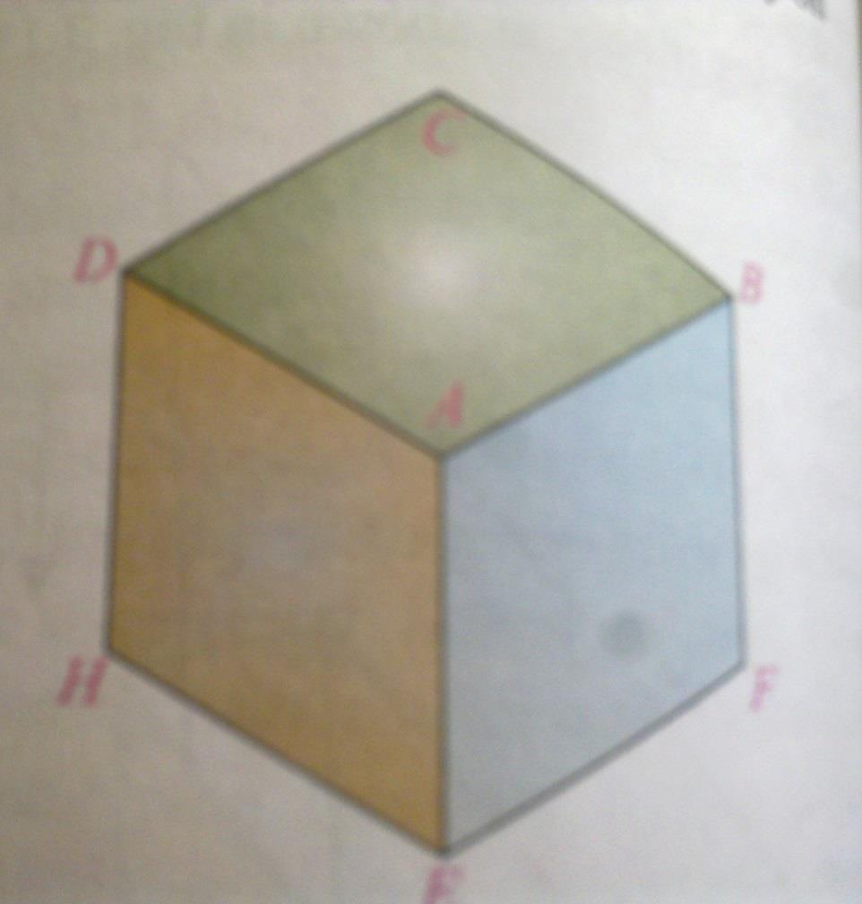
10 Isometric Projection The front and top view of an object resting in its simple position gives an incomplete idea of the shape of the object. When solid object is tilted from its simple position such that its axis is inclined to both horizontal and vertical planes, so fair idea of the object is obtained. All surfaces are viewed in a single view. Iso means equal and metric projection means a projection to reduced measure. An isometric projection is one type of pictorial projection in which the dimensions of a solid are not only shown in one view but also their dimensions can be scaled from this drawing.
11
12 Oblique projections It is parallel projection. The isometric projection of any object is pictorial view in distorted shapes with equal shortened dimensions. This means that the square,rectangle and circular faces are seen as a rhombus, parallelogram and ellipse respectively. An oblique projection is formed by parallel projections from a center of projection at infinity that intersects the plane of projection at an oblique angle, providing the general 3D shape of the object. Oblique means slanting.
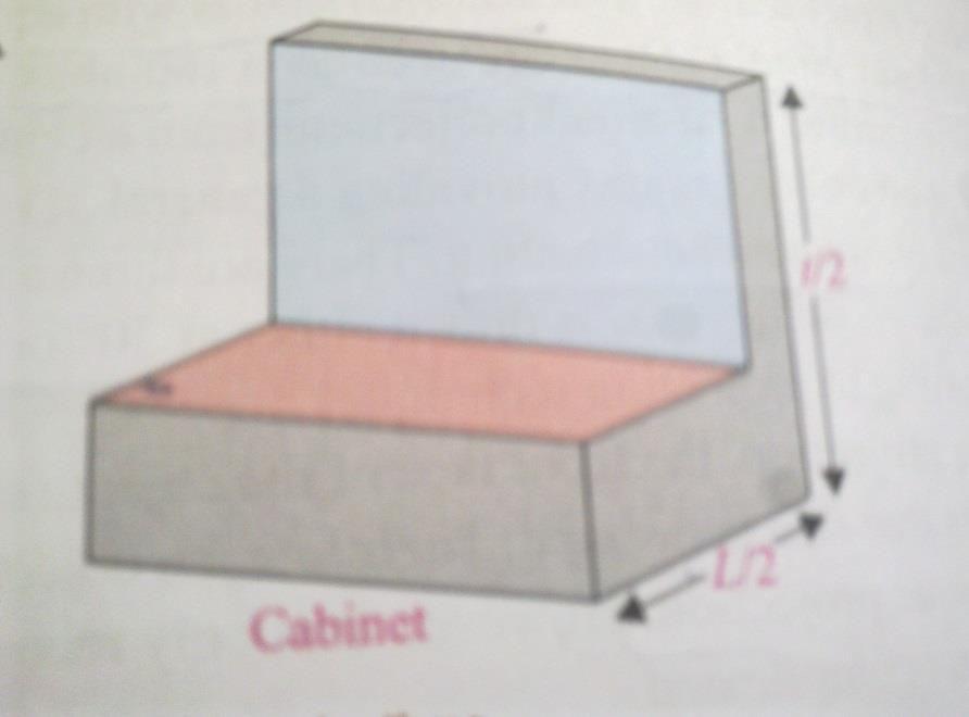
13 Oblique projections Projection lines are at an angle to the view plane. Let the angle be a be the angle the projection line makes with the view plane. tan a = 1 (or, a = 45 o ) called cavalier projection tan a = 2 (or, a = 63.4 o ) called cabinet projection 1 a 2 a 1 1 cavalier cabinet /2
14 Some In cavalier projection, the projection of a line perpendicular to the view plane has the same length as the line itself. In cabinet projection, the projection of a line perpendicular to the view plane has one half length as the line itself.

15
 (also called center of")
16 Perspective projection Projection lines are crossing the view plane and converge in a projection reference point (PRP) (also called center of projection)
17
18 Perspective vs. Parallel Perspective projection + Size varies inversely with distance - looks realistic Distance and angles are not (in general) preserved Parallel lines do not (in general) remain parallel Parallel projection + Good for exact measurements + Parallel lines remain parallel Angles are not (in general) preserved Less realistic looking
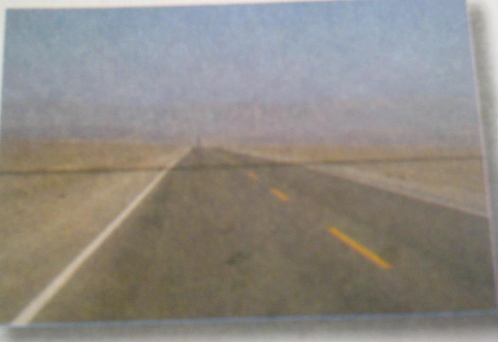
19 Again perspective projection Vanishing Point : the perspective projection of any set of parallel lines that are not parallel to the projection plane converge to a vanishing point. Category of perspective projection 1. 1 point perspective projection 2. 2 point perspective projection 3. 3 point perspective projection
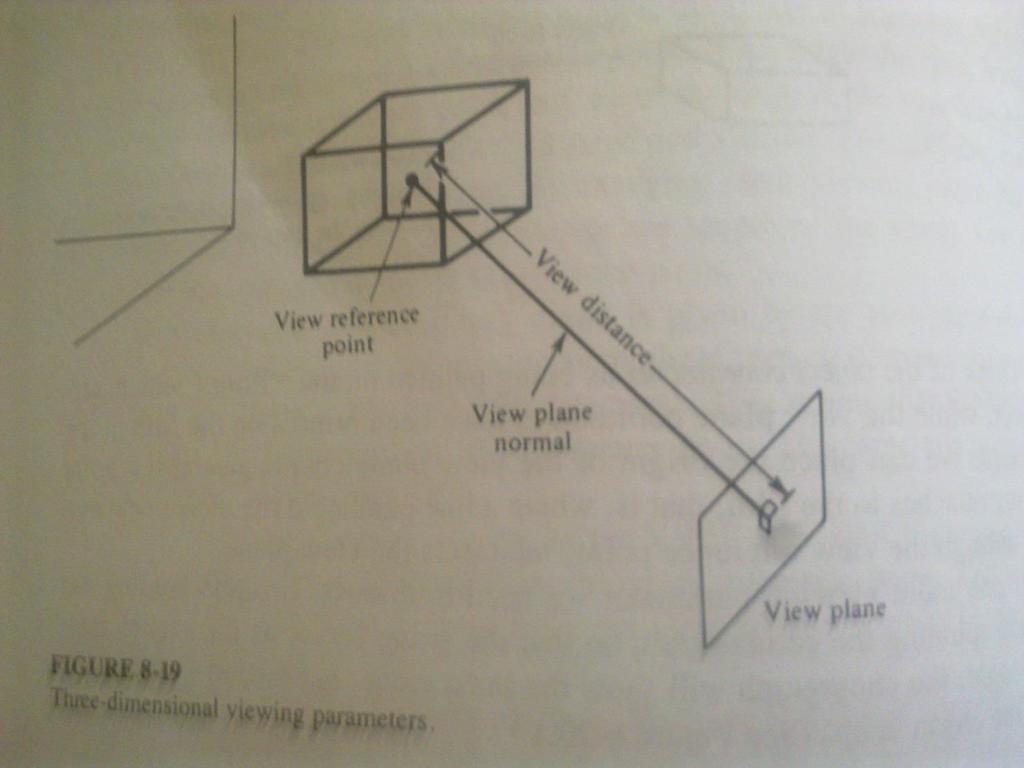
20 Viewing parameters
21
22 Viewing parameters We can view the object from the top, or the side or from the behind. Therefore, it is necessary to choose a particular view for a picture by defining view plane. View plane : it is film in the camera..on which we want to take photograph. View reference point: this point is the center of our viewing coordinate system. View plane normal vector: this normal vector is the direction perpendicular to the view plane. View distance: distance between the view plane and the view reference point.
23 It is possible to obtain the different views by rotating the camera about the view plane normal vector and keeping view reference point and direction of N vector fixed. view-up vector V :Rotation of camera or view plane is specified by view-up vector V
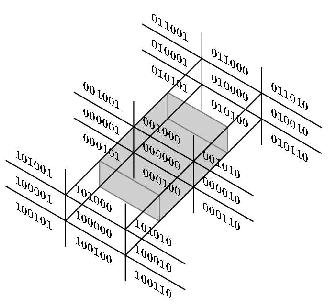
24 3D Clipping ( clipping against volume) Cube Both the Cohen-Sutherland and Cyrus-Beck clipping algorithm readily extend to 3D. For Cohen-Sutherland algorithm use two extra-bit in outcode for incorporating z < z min and z > z max regions We have to use 6bit outcode instead of 4-bit. Bit1 =1 if end point is to the left of the volume. Bit2 =1 if end point is to the right of the volume. Bit3 =1 if end point is to the bellow of the volume. Bit4 =1 if end point is to the above of the volume. Bit5 =1 if end point is to the front of the volume. Bit6 =1 if end point is to the back of the volume. Otherwise bit is set to zero.
25
Transform 3D objects on to a 2D plane using projections
 PROJECTIONS 1 Transform 3D objects on to a 2D plane using projections 2 types of projections Perspective Parallel In parallel projection, coordinate positions are transformed to the view plane along parallel
3D COMPUTER GRAPHICS
 3D COMPUTER GRAPHICS http://www.tutorialspoint.com/computer_graphics/3d_computer_graphics.htm Copyright tutorialspoint.com In the 2D system, we use only two coordinates X and Y but in 3D, an extra coordinate
3D Viewing. Introduction to Computer Graphics Torsten Möller / Manfred Klaffenböck. Machiraju/Zhang/Möller
 3D Viewing Introduction to Computer Graphics Torsten Möller / Manfred Klaffenböck Machiraju/Zhang/Möller Reading Chapter 5 of Angel Chapter 13 of Hughes, van Dam, Chapter 7 of Shirley+Marschner Machiraju/Zhang/Möller
technical drawing
 technical drawing school of art, design and architecture nust spring 2011 http://www.youtube.com/watch?v=q6mk9hpxwvo http://www.youtube.com/watch?v=bnu2gb7w4qs Objective abstraction - axonometric view
Reading. Angel. Chapter 5. Optional
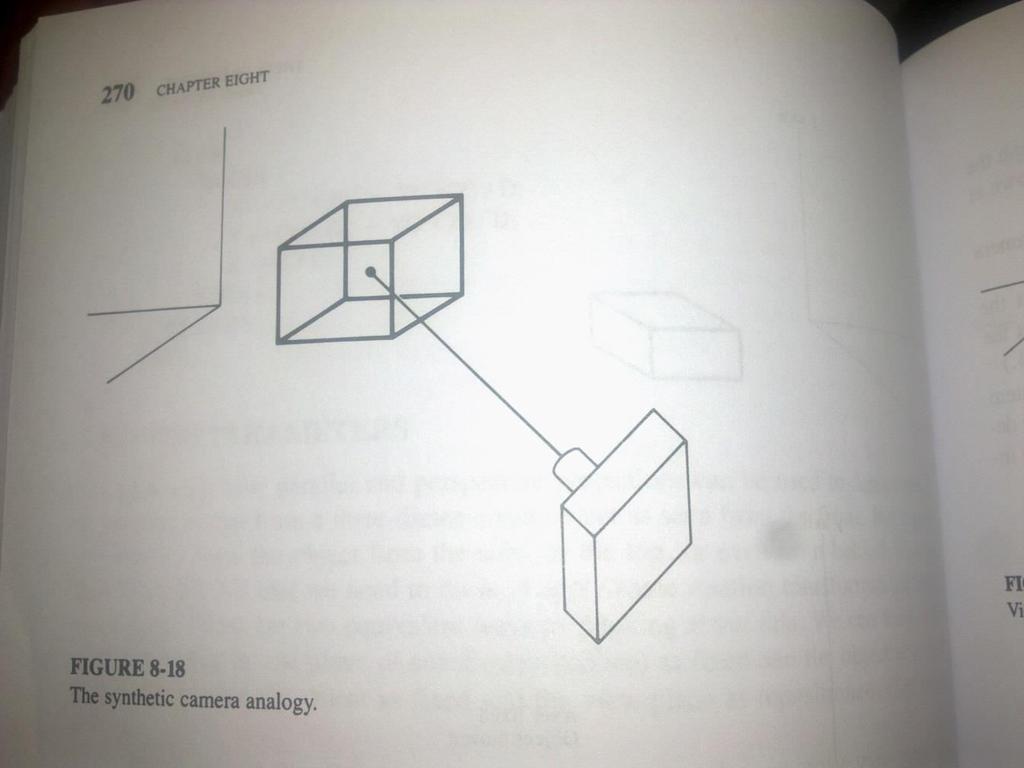
 Projections Reading Angel. Chapter 5 Optional David F. Rogers and J. Alan Adams, Mathematical Elements for Computer Graphics, Second edition, McGraw-Hill, New York, 1990, Chapter 3. The 3D synthetic camera
11/12/2015 CHAPTER 7. Axonometric Drawings (cont.) Axonometric Drawings (cont.) Isometric Projections (cont.) 1) Axonometric Drawings
 Axonometric Drawings (cont.) Isometric Projections (cont.) 1) Axonometric Drawings") CHAPTER 7 1) Axonometric Drawings 1) Introduction Isometric & Oblique Projection Axonometric projection is a parallel projection technique used to create a pictorial drawing of an object by rotating the
CHAPTER 7 1) Axonometric Drawings 1) Introduction Isometric & Oblique Projection Axonometric projection is a parallel projection technique used to create a pictorial drawing of an object by rotating the
3D Viewing I. Acknowledgement: Some slides are from the Dr. Andries van Dam lecture. CMSC 435/634 August D Viewing I # /27
 3D Viewing I Acknowledgement: Some slides are from the Dr. Andries van Dam lecture. From 3D to 2D: Orthographic and Perspective Projection Part 1 Geometrical Constructions Types of Projection Projection
Introduction to Computer Graphics (CS602) Lecture 19 Projections
 Lecture 19 Projections") Introduction to Computer Graphics (CS602) Lecture 19 Projections For centuries, artists, engineers, designers, drafters, and architects have been facing difficulties and constraints imposed by the problem
Introduction to Computer Graphics (CS602) Lecture 19 Projections For centuries, artists, engineers, designers, drafters, and architects have been facing difficulties and constraints imposed by the problem
Classical Viewing. Ed Angel Professor of Computer Science, Electrical and Computer Engineering, and Media Arts University of New Mexico
 Classical Viewing Ed Angel Professor of Computer Science, Electrical and Computer Engineering, and Media Arts University of New Mexico 1 Objectives Introduce the classical views Compare and contrast image
ENGINEERING GRAPHICS 1E9
 Lecture 3 Monday, 15 December 2014 1 ENGINEERING GRAPHICS 1E9 Lecture 3: Isometric Projections Lecture 3 Monday, 15 December 2014 2 What is ISOMETRIC? It is a method of producing pictorial view of an object
I B.TECH- I SEMESTER DEPARTMENT OF MECHANICAL ENGINEERING ENGINEERING DRAWING
 I B.TECH- I SEMESTER DEPARTMENT OF MECHANICAL ENGINEERING ENGINEERING DRAWING ENGINEERING DRAWING UNIT-V DEFINITIONS: Axonometric Trimetric Dimetric Isometric It is a parallel technique used to create
1. When sketching long, narrow objects in OBLIQUE, distortion can be lessened by placing the long dimension along:
 Draft Student Name: Teacher: District: Date: Wake County Test: 9_12 T and I IC61 - Drafting I Test 2 Description: 3.03 Apply 3D sketching Form: 501 1. When sketching long, narrow objects in OBLIQUE, distortion
Isometric Drawing Chapter 26
 Isometric Drawing Chapter 26 Sacramento City College EDT 310 EDT 310 - Chapter 26 - Isometric Drawing 1 Drawing Types Pictorial Drawing types: Perspective Orthographic Isometric Oblique Pictorial - like
Interactive Computer Graphics A TOP-DOWN APPROACH WITH SHADER-BASED OPENGL
 International Edition Interactive Computer Graphics A TOP-DOWN APPROACH WITH SHADER-BASED OPENGL Sixth Edition Edward Angel Dave Shreiner 228 Chapter 4 Viewing Front elevation Elevation oblique Plan oblique
CS354 Computer Graphics Viewing and Projections
 Slide Credit: Donald S. Fussell CS354 Computer Graphics Viewing and Projections Qixing Huang February 19th 2018 Eye Coordinates (not NDC) Planar Geometric Projections Standard projections project onto
Chapter 5 Pictorial sketching
 Chapter 5 Pictorial sketching Contents Freehand sketching techniques Pictorial projections - Axonometric - Oblique Isometric projection vs isometric sketch Isometric sketch from an orthographic views Isometric
Engineering Drawing Lecture 5 PROJECTION THEORY
 University of Palestine College of Engineering & Urban Planning First Level Engineering Drawing Lecture 5 PROJECTION THEORY Lecturer: Eng. Eman Al.Swaity Eng.Heba hamad PART 1 PROJECTION METHOD TOPICS
Reading. Projections. The 3D synthetic camera model. Imaging with the synthetic camera. Angel. Chapter 5. Optional
 Reading Angel. Chapter 5 Optional Projections David F. Rogers and J. Alan Adams, Mathematical Elements for Computer Graphics, Second edition, McGraw-Hill, New York, 1990, Chapter 3. The 3D snthetic camera
Graphic Communications
 Graphic Communications Lecture 8: Projections Assoc. Prof.Dr. Cengizhan İpbüker İTÜ-SUNY 2004-2005 2005 Fall ipbuker_graph06 Projections The projections used to display 3D objects in 2D are called Planar
3D Viewing I. From 3D to 2D: Orthographic and Perspective Projection Part 1
 From 3D to 2D: Orthographic and Perspective Projection Part 1 3D Viewing I By Andries van Dam Geometrical Constructions Types of Projection Projection in Computer Graphics Jian Chen January 15, 2010 3D
Projections Computer Graphics and Visualization
 Planar Geometric Fall 2010 Standard projections project onto a plane Projectors are lines that either converge at a center of projection are parallel Nonplanar projections are needed for applications such
Isometric Projection Drawing CHAPTER 6
 Isometric Projection Drawing CHAPTER 6 Content Overview Pictorial projection Parallel projection Axonometric projection Isometric projection Axes and selection Isometric lines and planes Isometric scale
Introduction to Projection The art of representing a three-dimensional object or scene in a 2D space is called projection.
 Introduction to Projection The art of representing a three-dimensional object or scene in a 2D space is called projection. Projection is carried out by passing projectors through each vertex and intersecting
1 st Subject: Types of Pictorial Drawings (Isometric, Oblique, and Perspective)
") Intermediate Engineering Graphics 4 th Week 1 st Meeting Lecture Notes Instructor: Edward N. Locke Topic: Types of pictorial drawings (isometric, oblique, and perspective), isometric sketching and drafting
Intermediate Engineering Graphics 4 th Week 1 st Meeting Lecture Notes Instructor: Edward N. Locke Topic: Types of pictorial drawings (isometric, oblique, and perspective), isometric sketching and drafting
Student Name: Teacher: Date: District: Rowan. Assessment: 9_12 T and I IC61 - Drafting I Test 1. Description: Unit C - Sketching - Test 2.
 Student Name: Teacher: Date: District: Rowan Assessment: 9_12 T and I IC61 - Drafting I Test 1 Description: Unit C - Sketching - Test 2 Form: 501 1. The most often used combination of views includes the:
Beginning Engineering Graphics 3 rd Week Lecture Notes Instructor: Edward N. Locke Topic: The Coordinate System, Types of Drawings and Orthographic
 Beginning Engineering Graphics 3 rd Week Lecture Notes Instructor: Edward N. Locke Topic: The Coordinate System, Types of Drawings and Orthographic 1 st Subject: The Cartesian Coordinate System The Cartesian
CS475/CS675 Computer Graphics
 CS475/CS675 Computer Graphics Viewing Perspective Projection Projectors Centre of Projection Object Image Plane or Projection Plane 2 Parallel Projection Projectors Centre of Projection? Object Image Plane
60 Most Important Engineering Drawing Questions
 1. If a client of yours is having difficulty visualizing a design, what type of drawing would be the easiest to understand? A. axonometric B. three-view orthographic C. one-view orthographic D. bimetric
Orthographic Projection
 Orthographic Projection Why Orthographic Projection is used in technical drawing Orthographic projection is a method of producing a number of separate two-dimensional inter-related views, which are mutually
Exploring 3D in Flash
 1 Exploring 3D in Flash We live in a three-dimensional world. Objects and spaces have width, height, and depth. Various specialized immersive technologies such as special helmets, gloves, and 3D monitors
1 ISOMETRIC PROJECTION SECTION I: INTRODUCTION TO ISOMETRIC PROJECTION
 1 ISOMETRIC PROJECTION SECTION I: INTRODUCTION TO ISOMETRIC PROJECTION Orthographic projection shows drawings of an object in a two-dimensional format, with views given in plan, elevation and end elevation
Chapter 5 Pictorial Projection
 Chapter 5 Pictorial Projection Objectives After completing this chapter, the students will be able to Create freehand sketches using the correct sketching techniques. Explainthe difference between axonometric
MULTIPLE CHOICE QUESTIONS - CHAPTER 6
 MULTIPLE CHOICE QUESTIONS - CHAPTER 6 1. The selection of the front view in executing a multiview drawing of an object is dependent upon the following factors: a. size and shape of the object and their
(Ans:d) a. A0 b. A1 c. A2 d. A3. (Ans:b) (Ans:a) (Ans:d) (Ans:d)
 a. A0 b. A1 c. A2 d. A3. (Ans:b) (Ans:a) (Ans:d) (Ans:d)") Multiple Choice Questions (MCQ) on Engineering Drawing (Instruments) The mini drafter serves the purpose of everything except a. Scales b. Set square c. Protractor d. Compass (Ans:d) During operation,
Multiple Choice Questions (MCQ) on Engineering Drawing (Instruments) The mini drafter serves the purpose of everything except a. Scales b. Set square c. Protractor d. Compass (Ans:d) During operation,
ENGINEERING DRAWING. 1. Set squares are used to draw different angles. What is the angel a formed by the 45⁰ set square? Give a brief answer.
 ENGINEERING DRAWING 1. Set squares are used to draw different angles. What is the angel a formed by the 45⁰ set square? Give a brief answer. 2. Which is the correct method of hatching a plane surface?
3D Viewing. Projections. Perspective A B B. Projectors. Center of Projection. Projection Plane
 Projections Projectors A Center of Projection A B B Projection Plane Perspective Projections Projectors A A B At Infinit B Projection Plane Parallel Parallel Projections Orthographic 3D Viewing Top View
Copyrighted Material. Copyrighted Material. Copyrighted. Copyrighted. Material
 Engineering Graphics ORTHOGRAPHIC PROJECTION People who work with drawings develop the ability to look at lines on paper or on a computer screen and "see" the shapes of the objects the lines represent.
Graphics and Interaction Perspective Geometry
 433-324 Graphics and Interaction Perspective Geometr Department of Computer Science and Software Engineering The Lecture outline Introduction to perspective geometr Perspective Geometr Centre of projection
History of projection. Perspective. History of projection. Plane projection in drawing
 History of projection Ancient times: Greeks wrote about laws of perspective Renaissance: perspective is adopted by artists Perspective CS 4620 Lecture 3 Duccio c. 1308 1 2 History of projection Plane projection
Pictorial Drawings. DFTG-1305 Technical Drafting Prepared by Francis Ha, Instructor
 DFTG-1305 Technical Drafting Prepared by Francis Ha, Instructor Pictorial Drawings Geisecke s textbook for reference: 14 th Ed. Ch. 15: p. 601 Ch. 16: p. 620 15 th Ed. Ch. 14: p. 518 Ch. 15: p. 552 Update:
PROJECTIONS PARALLEL CONICAL PROJECTIONS PROJECTIONS OBLIQUE ORTHOGRAPHIC PROJECTIONS PROJECTIONS
 PROJECTIONS CONICAL PROJECTIONS PARALLEL PROJECTIONS OBLIQUE PROJECTIONS ORTHOGRAPHIC PROJECTIONS ISOMETRIC MULTI-VIEW an object; The Description of Forms Behind every drawing of an object is space relationship
Chapter 8. Technical Drawings
 Chapter 8 Technical Drawing Technical Drawings Multiview drawings Also called three-view drawings Simple objects take three views Front, top, one side Title block Identifies who did the design Gives date,
Perspective. Announcement: CS4450/5450. CS 4620 Lecture 3. Will be MW 8:40 9:55 How many can make the new time?
 Perspective CS 4620 Lecture 3 1 2 Announcement: CS4450/5450 Will be MW 8:40 9:55 How many can make the new time? 3 4 History of projection Ancient times: Greeks wrote about laws of perspective Renaissance:
ME1105 Engineering Drawing & Design
 City University London Term 1 Assessment 2008/2009 School of Engineering and Mathematical Sciences ME1105 Engineering Drawing & Design Student Name:.., Group: Examination duration: Reading time: This paper
Chapter 1 Overview of a Technical Drawing
 Chapter 1 Overview of a Technical Drawing TOPICS Graphics language Engineering drawing Projection methods Orthographic projection Drawing standards TOPICS Traditional Drawing Tools Lettering Dimensioning
CHAPTER 01 PRESENTATION OF TECHNICAL DRAWING. Prepared by: Sio Sreymean
 CHAPTER 01 PRESENTATION OF TECHNICAL DRAWING Prepared by: Sio Sreymean 2015-2016 Why do we need to study this subject? Effectiveness of Graphics Language 1. Try to write a description of this object. 2.
ENGINEERING GRAPHICS UNIT V ISOMETRIC PROJECTION PERSPECTIVE PROJECTION
 ENGINEERING GRAPHICS UNIT V ISOMETRIC PROJECTION PERSPECTIVE PROJECTION 1.PICTORIAL PROJECTIONS To visualize the shape of the whole object in its 3- D form, all the two or three orthographic views of the
Page 1 of 5. ENGINEERING SKETCHES INFORMATION SHEETS MEL02INF2430 v1.1 HEALTH & SAFETY REQUIREMENTS
 Page 1 of 5 Competenz - N Z Engineering Food & Manufacturing Industry Training Organisation Inc. ENGINEERING SKETCHES INFORMATION SHEETS MEL02INF2430 v1.1 HEALTH & SAFETY REQUIREMENTS RECORDING REQUIREMENTS:
Chapter 1 Overview of an Engineering Drawing
 Chapter 1 Overview of an Engineering Drawing TOPICS Graphics language Engineering drawing Projection methods Orthographic projection Drawing standards TOPICS Traditional Drawing Tools Lettering Freehand
Bridge Course On Engineering Drawing for Mechanical Engineers
 G. PULLAIAH COLLEGE OF ENGINEERING AND TECHNOLOGY Accredited by NAAC with A Grade of UGC, Approved by AICTE, New Delhi Permanently Affiliated to JNTUA, Ananthapuramu (Recognized by UGC under 2(f) and 12(B)
Extension material for Level 2 Design and Visual Communication Study Guide
 3-D formal drawing Extension material for Level 2 Design and Visual Communication Study Guide ISBN 978-1-927194-15-7 For individual student use only. No other use permitted. ESA Publications (NZ) Ltd,
ISOMETRIC PROJECTION. Contents. Isometric Scale. Construction of Isometric Scale. Methods to draw isometric projections/isometric views
 ISOMETRIC PROJECTION Contents Introduction Principle of Isometric Projection Isometric Scale Construction of Isometric Scale Isometric View (Isometric Drawings) Methods to draw isometric projections/isometric
2. Line composed of closely and evenly spaced short dashes in a drawing represents
 1. Hidden lines are drawn as (a) dashed narrow lines (b) dashed wide lines (c) long-dashed dotted wide line (d) long-dashed double dotted wide line Ans: (a) 2. Line composed of closely and evenly spaced
ORTHOGRAPHIC PROJECTION
 ORTHOGRAPHIC PROJECTION C H A P T E R S I X OBJECTIVES 1. Recognize and the symbol for third-angle projection. 2. List the six principal views of projection. 3. Understand which views show depth in a drawing
TIME SCHEDULE. Module Topic Periods 1 Importance of Engineering Graphics Drawing Instruments Drawing Standards Lettering and Numbering
 COURSE TITLE : ENGINEERING GRAPHICS (First Semester) COURSE CODE : COURSE CATEGORY : F PERIODS/WEEK : 3 PERIODS/SEMESTER : 54 CREDITS : Examination in the Second Semester RATIONALE: Engineering Graphics
UNIT 5a STANDARD ORTHOGRAPHIC VIEW DRAWINGS
 UNIT 5a STANDARD ORTHOGRAPHIC VIEW DRAWINGS 5.1 Introduction Orthographic views are 2D images of a 3D object obtained by viewing it from different orthogonal directions. Six principal views are possible
Engineering Graphics with SOLIDWORKS 2016 and Video Instruction
 Engineering Graphics with SOLIDWORKS 2016 and Video Instruction A Step-by-Step Project Based Approach David C. Planchard, CSWP, SOLIDWORKS Accredited Educator SDC PUBLICATIONS Better Textbooks. Lower Prices.
Reading. Projections. Projections. Perspective vs. parallel projections. Foley et al. Chapter 6. Optional. Perspective projections pros and cons:
 Reading Fole et al. Chapter 6 Optional Projections David F. Rogers and J. Alan Adams, Mathematical Elements for Computer Graphics, Second edition, McGra-Hill, Ne York, 990, Chapter 3. Projections Projections
VIEWING 1. CLASSICAL AND COMPUTER VIEWING. Computer Graphics
 VIEWING We now investigate the multitude of ways in which we can describe our virtual camera. Along the way, we examine related topics, such as the relationship between classical viewing techniques and
Drawing: technical drawing TECHNOLOGY
 Drawing: technical drawing Introduction Humans have always used images to communicate. Cave paintings, some of which are over 40,000 years old, are the earliest example of this artistic form of communication.
Learning Outcomes. Students should be able to: Demonstrate an understanding of the planes of reference
 Orthographic projection is a means of representing a three-dimensional (3D) object in two dimensions (2D). It is the projection by parallel rays onto a plane at right angles to the rays. Demonstrate an
Chapter 2. Isometric Projection and Multi View Drawings. Below are the desired outcomes and usage competencies based on the completion of Chapter 2.
 Chapter 2 Below are the desired outcomes and usage competencies based on the completion of Chapter 2. Desired Outcomes: Understand Isometric Projection and 2D sketching. Knowledge of additional Projection
ONE-POINT PERSPECTIVE
 NAME: PERIOD: PERSPECTIVE Linear Perspective Linear Perspective is a technique for representing 3-dimensional space on a 2- dimensional (paper) surface. This method was invented during the Renaissance
Change of position method:-
 Projections of Planes PROJECTIONS OF PLANES A plane is a two dimensional object having length and breadth only. Thickness is negligible. Types of planes 1. Perpendicular plane which have their surface
Lecture 2 of 41. Viewing 1 of 4: Overview, Projections
 Viewing 1 of 4: Overview, Projections William H. Hsu Department of Computing and Information Sciences, KSU KSOL course pages: http://bit.ly/hgvxlh / http://bit.ly/evizre Public mirror web site: http://www.kddresearch.org/courses/cis636
Lecture 2 of 41. Viewing 1 of 4: Overview, Projections
 Viewing 1 of 4: Overview, Projections William H. Hsu Department of Computing and Information Sciences, KSU KSOL course pages: http://bit.ly/hgvxlh / http://bit.ly/evizre Public mirror web site: http://www.kddresearch.org/courses/cis636
Technical Graphics Higher Level
 Coimisiún na Scrúduithe Stáit State Examinations Commission Junior Certificate Examination 2005 Technical Graphics Higher Level Marking Scheme Sections A and B Section A Q1. 12 Four diagrams, 3 marks for
Describing an Angle Bracket
 Basics of Drafting Describing an Angle Bracket Orthographic Projection Orthographic drawings represent three dimensional objects in three separate views arranged in a standard manner. Orthographic Views
Unit-5 ISOMETRIC PROJECTION
 Unit-5 ISOMETRIC PROJECTION Importance Points in Isometric: 1. For drawing the isometric, the object must be viewed such that either the front -right or the left edges becomes nearest. 2. All vertical
Add labels to the sides...
 Orthographic Drawings Orthographic Projection A projection on a plane, using lines perpendicular to the plane Graphic communications has many forms. Orthographics is one such form. It was developed as
Engineering Graphics with SolidWorks 2012
 INSIDE: Video Instruction DVD An audio/visual presentation of the tutorial projects Engineering Graphics with SolidWorks 2012 and Video Instruction DVD A Step-by-Step Project Based Approach Introductory
Drawing Types & Construction Drawings
 Drawing Types & Construction Drawings Building projects require several types of specialised drawings. This collection of drawings, known as a project set, includes: Location Plan Site Plan Floor Plan
Projections Josef Pelikán & Alexander Wilkie CGG MFF UK Praha
 Projections 995-205 Josef Pelikán & Aleander Wilkie CGG MFF UK Praha pepca@cgg.mff.cuni.c http://cgg.mff.cuni.c/~pepca/ / 24 Basic Concepts plane of projection projection ras projection origin plane of
ENGINEERING GRAPHICS
 ENGINEERING GRAPHICS Course Structure Units Topics Marks Unit I Plane Geometry 16 1 Lines, angles and rectilinear figures 2 Circles and tangents 3 Special curves: ellipse, parabola, involute, cycloid.
6. Draw the isometric view of a cone 40 mm diameter and axis 55 mm long when its axis is horizontal. Draw isometric scale. [16]
![6. Draw the isometric view of a cone 40 mm diameter and axis 55 mm long when its axis is horizontal. Draw isometric scale. [16]](/thumbs/85/92603403.jpg "6. Draw the isometric view of a cone 40 mm diameter and axis 55 mm long when its axis is horizontal. Draw isometric scale. [16]") Code No: R05010107 Set No. 1 I B.Tech Supplimentary Examinations, Aug/Sep 2007 ENGINEERING GRAPHICS ( Common to Civil Engineering, Mechanical Engineering, Mechatronics, Metallurgy & Material Technology,
Code No: R05010107 Set No. 1 I B.Tech Supplimentary Examinations, Aug/Sep 2007 ENGINEERING GRAPHICS ( Common to Civil Engineering, Mechanical Engineering, Mechatronics, Metallurgy & Material Technology,
ENGINEERING COMMUNICATIONS. Student Number:.
 The University of Melbourne Semester 2 Assessment, 1999 Department of Mechanical and Manufacturing Engineering 436-105 ENGINEERING COMMUNICATIONS Student Number:. Examination duration: Reading time: This
Perspective. Cornell CS4620/5620 Fall 2012 Lecture Kavita Bala 1 (with previous instructors James/Marschner)
") CS4620/5620: Lecture 6 Perspective 1 Announcements HW 1 out Due in two weeks (Mon 9/17) Due right before class Turn it in online AND in class (preferably) 2 Transforming normal vectors Transforming surface
CS4620/5620: Lecture 6 Perspective 1 Announcements HW 1 out Due in two weeks (Mon 9/17) Due right before class Turn it in online AND in class (preferably) 2 Transforming normal vectors Transforming surface
CS337 INTRODUCTION TO COMPUTER GRAPHICS. Viewing. Part I (History and Overview of Projections) Bin Sheng 1 / 46 10/04/2016
 Bin Sheng 1 / 46 10/04/2016") Viewing Part I (History and Overview of Projections) 1 / 46 Lecture Topics History of projection in art Geometric constructions Types of projection (parallel and perspective) 2 / 46 CS337 INTRODUCTION
Viewing Part I (History and Overview of Projections) 1 / 46 Lecture Topics History of projection in art Geometric constructions Types of projection (parallel and perspective) 2 / 46 CS337 INTRODUCTION
Appendix. Springer International Publishing Switzerland 2016 A.Y. Brailov, Engineering Graphics, DOI /
 Appendix See Figs. A.1, A.2, A.3, A.4, A.5, A.6, A.7, A.8, A.9, A.10, A.11, A.12, A.13, A.14, A.15, A.16, A.17, A.18, A.19, A.20, A.21, A.22, A.23, A.24, A.25, A.26, A.27, A.28, A.29, A.30, A.31, A.32,
Technological Design Mr. Wadowski. Orthographic & Isometric Drawing Lesson
 Technological Design Mr. Wadowski Orthographic & Isometric Drawing Lesson TOPICS Working Drawings, Isometric Drawings & Orthographic Drawings Glass box concept Multiview projection Orthographic projection
Design & Communication Graphics
 L.84/85 Design & Communication Graphics Marking Scheme Ordinary Pg. 3 Higher Pg. 12 2013 L.84/85_MS 1/20 2013 L.84/85_MS 2/20 SECTION A - Core - Answer Any Three of the questions on this A3 sheet A-1.
Reading. 8. Projections. 3D Geometry Pipeline. 3D Geometry Pipeline (cont d) Required: w Watt, Section
 Required: w Watt, Section") Reading Required: Watt, Section 5.2.2 5.2.4. Further reading: 8. Projections Fole, et al, Chapter 5.6 and Chapter 6 David F. Rogers and J. Alan Adams, Mathematical Elements for Computer Graphics, 2 nd
Reading Required: Watt, Section 5.2.2 5.2.4. Further reading: 8. Projections Fole, et al, Chapter 5.6 and Chapter 6 David F. Rogers and J. Alan Adams, Mathematical Elements for Computer Graphics, 2 nd
ENGINEERING GRAPHICS 1.0 Introduction Engineering Graphics Drawing as an art Artist Graphic design Engineering graphics engineering drawing
 ENGINEERING GRAPHICS 1.0 Introduction Engineering is the profession in which the knowledge of mathematics and science gained by study, experience and practice is applied with good judgment to develop a
DMT113 Engineering Drawing. Chapter 3 Stretch System
 DMT113 Engineering Drawing Chapter 3 Stretch System Contents Theory & Multiview Planes 6 Principle Views Multiview Sketching Technique & Perspective First & Third Angle Multiview Representations Theory
Design & Communication Graphics Higher Level Section A (60 Marks)
") M.85A ªM.858 Leaving Certificate Examination, 2009 Design & Communication Graphics Higher Level Section A (60 Marks) Time: 3 Hours This examination is divided into three sections: SECTION A SECTION B SECTION
M.85A ªM.858 Leaving Certificate Examination, 2009 Design & Communication Graphics Higher Level Section A (60 Marks) Time: 3 Hours This examination is divided into three sections: SECTION A SECTION B SECTION
ENGINEERING GRAPHICS
 ENGINEERING GRAPHICS CLASS - XII (046) DESIGN OF THE QUESTION PAPER Time : 3 Hrs Max. Marks : 70 The weightage of the distribution of marks over different contents of the question paper shall be as follows:
ENGR 1182 Exam 1 First Mid Term Exam Study Guide and Practice Problems
 Spring Semester 2016 ENGR 1182 Exam 1 First Mid Term Exam Study Guide and Practice Problems Disclaimer Problems in this study guide resemble problems relating mainly to the pertinent homework assignments.
Technology Education Grades Drafting I
 Technology Education Grades 9-12 Drafting I 46 Grade Level: 9, 10, 11, 12 Technology Education, Grades 9-12 Drafting I Prerequisite: None Drafting I is an elective course which provides students the opportunity
Perspective in 2D Games
 Lecture 16 in 2D Games Drawing Images Graphics Lectures SpriteBatch interface Coordinates and Transforms bare minimum to draw graphics Drawing Camera Projections side-scroller vs. top down Drawing Primitives
UNIT I PLANE CURVES AND FREE HAND SKETCHING CONIC SECTIONS
 UNIT I PLANE CURVES AND FREE HAND SKETCHING CONIC SECTIONS Definition: The sections obtained by the intersection of a right circular cone by a cutting plane in different positions are called conic sections
Perspective. CS 4620 Lecture Steve Marschner. Cornell CS4620 Spring 2018 Lecture 5
 Perspective CS 4620 Lecture 5 2018 Steve Marschner 1 Parallel projection To render an image of a 3D scene, we project it onto a plane Simplest kind of projection is parallel projection image projection
technical drawing school of art, design and architecture sarah adeel nust spring 2011
 technical drawing school of art, design and architecture sarah adeel nust spring 2011 the ability to document imagination. a mean to design reasoning spring 2011 perspective drawings technical drawing
ENGINEERING DRAWING SKKK 1021 ISOMETRIC DRAWING. Agus Arsad, Azizul Azri Bin Mustaffa 10/2/2012 1
 ENGINEERING DRAWING SKKK 1021 ISOMETRIC DRAWING Agus Arsad, Azizul Azri Bin Mustaffa 10/2/2012 1 LEARNING OUTCOMES ISOMETRIC DRAWING It is expected that students will be able to: Understand the significance
Graphical Communication
 Chapter 9 Graphical Communication mmm Becoming a fully competent engineer is a long yet rewarding process that requires the acquisition of many diverse skills and a wide body of knowledge. Learning most
Tile based games. Piotr Fulma«ski. 8 pa¹dziernika Wydziaª Matematyki i Informatyki, Uniwersytet Šódzki, Polska
 Tile based games Piotr Fulma«ski Wydziaª Matematyki i Informatyki, Uniwersytet Šódzki, Polska 8 pa¹dziernika 2015 Table of contents Aim of this lecture In this lecture we discusse how axonometric projections
DELHI TECHNOLOGICAL UNIVERSITY ENGINEERING GRAPHICS LAB MANUAL
 DELHI TECHNOLOGICAL UNIVERSITY ENGINEERING GRAPHICS LAB MANUAL NAME: - ROLL NO: - GROUP: - BRANCH: - GROUP TEACHER: Page 1 www.rooplalrana.com 1 GENERAL INSTRUCTIONS FOR ENGG. GRAPHICS LAB 1) Students
2003 Academic Challenge
 Worldwide Youth in Science and Engineering 2003 Academic Challenge ENGINEERING GRAPHICS TEST - SECTIONAL Engineering Graphics Test Production Team Ryan Brown, Illinois State University Author/Team Coordinator
Engineering Working Drawings Basics
 Engineering Working Drawings Basics Engineering graphics is an effective way of communicating technical ideas and it is an essential tool in engineering design where most of the design process is graphically
NAME: PERIOD: Perspective Packet (Week One)
") NAME: PERIOD: Perspective Packet (Week One) The following are your beginning assignments for perspective. You are to complete ONE page at a time. When you finish each page show it to me to sign off and
NAME: PERIOD: Perspective Packet (Week One) The following are your beginning assignments for perspective. You are to complete ONE page at a time. When you finish each page show it to me to sign off and
Perspective in 2D Games
 Lecture 16 in 2D Games Take Away for Today What is game camera? How does it relate to screen space? Object space? How does camera work in a 2D game? 3D? How do we give 2D games depth? Advantages, disadvantages