Introduction to Parametric Modeling AEROPLANE. Design & Communication Graphics 1
|
|
|
- Nathan Rose
- 6 years ago
- Views:
Transcription

1 AEROPLANE Design & Communication Graphics 1
2 Object Analysis sheet Design & Communication Graphics 2


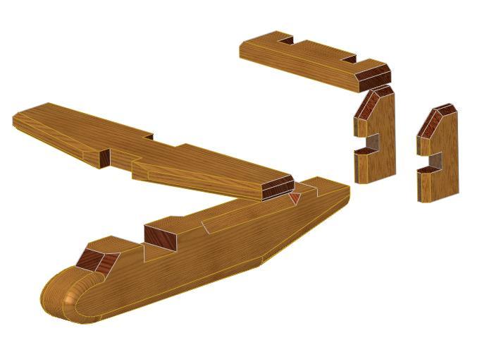
3 Aeroplane Assembly The part files for this assembly are saved in the folder titled Aeroplane. Open an existing part Open the part called Aeroplane body. Click Make Assembly from Part/Assembly. Insert component dialog box appears with Aeroplane body displayed. Click on in the property manager. The part origin will snap to the origin of the assembly. Save Select File, Save as on the standard toolbar. Save the assembly as Aeroplane Assembly in the same folder as its parts. Adding Component Select Insert component from the Assembly toolbar. Choose Browse from the Insert Component dialog box. Choose Front Wing and click in the graphics area to place it in as shown. Insert Mates Select the mate toolbar. Mate the front face of the trench on the aeroplane body with the bottom of the trench on the wing. A Coincident Mate will be selected by default. Accept. Design & Communication Graphics 3


4 Mate the bottom of the trench on the body with the underside of the wing. Accept Finally mate the side of the body with the side of the trench on the wing Accept Select OK again to exit the property manager. Adding Further Parts Select Insert Component from the assembly toolbar. Choose the horizontal tail wing. Insert Mates Mate the front of the horizontal tail with the shoulder shown A Concentric Mate will be chosen by default. Accept this mate. Mate the underside of the tail wing with the recess Additional Mates The horizontal tail wing has to be centered on the plane body One way to do this is as follows. Expand the design trees of the two parts and mate the Front planes of each as shown.. Design & Communication Graphics 4


5 A coincident mate is selected by default Accept the mate. Select OK again to exit the property manager. Adding Vertical Tail Wing Select Insert Component from the assembly toolbar Choose the Vertical tail wing and drag it into position. Insert Mates Mate the bottom of each trench. Accept. Mate the side of the vertical tail with the side of the trench on the horizontal wing Accept Mate the side of the trench on the vertical tail with the side of the horizontal wing Accept. Select OK again to exit the property manager. Follow the process again to insert the other vertical tail wing. Design & Communication Graphics 5

 Dragging the relevant arrow (in this instance the green one) to the required")
 By scrolling down the explode property manager and selecting the part to explode as shown.")
6 Exploded View Click the Exploded View button on the Assembly toolbar. The Exploded view dialog box appears. Exploding Front wing To move the front wing, select it as shown Explode View Explode by one of two methods: 1) Dragging the relevant arrow (in this instance the green one) to the required distance. 2) By scrolling down the explode property manager and selecting the part to explode as shown. Select the direction (x, y or z) by clicking the relevant arrow, and insert the distance Select Apply to preview the selection. Select Done to accept. Design & Communication Graphics 6


7 Select ok to exit the property manager. Exploding the Vertical Tail Wings Select the Explode View button again. Select the two vertical tail wings. The move manipulator arrows appear. Select the X direction arrow and drag outwards or insert a distance of 80mm as shown. Accept Explode the Horizontal Tail Wing Select Exploded view as before. Select the horizontal tail wing. Drag the green arrow away from the assembly. Insert the distance of 80mm. Click Apply and Done. Accept Design & Communication Graphics 7


8 Saving the desired Exploded view Press the space bar to show the Orientation dialog box. Select New View as shown. Name it as Front Pictorial This view is now added to the list of views. Animating the Exploded View The Animation Controller can be used to animate the explode or collapse motion. Right click on Aeroplane Assembly as shown and select Animation collapse. The animation controller display appears. Select play or loop. The Collapse motion will be shown. To show the Animation Explode motion, Select the animation explode in the same way. Design & Communication Graphics 8


9 Save Save AEROPLANE ASSEMBLY in the Collapsed View Creating the Drawing To make drawing from Part/Assembly see the notes on Creating Drawings from R6 in-service. Click on Make Drawing in the Standard Icon Toolbar as shown. Choosing a Drawing Template Select the A3L template Select OK Model View The Model View property manager is displayed In the property manager make sure the front view is selected. Tick the preview button. Scale Set the scale to 1:1.5. Design & Communication Graphics 9


10 Ensure that start projected view is ticked so that further views are projected once the first one is positioned. Positioning the Views Position the front view on the sheet. Drag the courser to the right to project an end view. Drag down to project a plan. Project an isometric view by dragging the courser to the top corner of the front view shown. To position this isometric view in the required location hold down the ctrl key while dragging. Change the scale of this view by selecting the box shown and changing the scale to 1:3 Change its display style to Shaded with Edges. Inserting Dimensions Select Model items from the Annotations toolbar. Design & Communication Graphics 10


11 Choose the entire model as the source. Tick select all dimensions. Select ok to accept. Delete some of the dimensions that are not needed. In the Annotation toolbar select Note and name the views. Drawing Exploded View Adding Sheet2 Right click on Sheet 1 tab (located at bottom left of graphics area) and select Add Sheet Change the scale to 1:1. Accept. Sheet2 now becomes the current sheet Select the Drawings toolbar and Model views IN the Model view command manager select browse and open Aeroplane Assembly. Design & Communication Graphics 11


12 The front view is selected by default. To select the desired view tick Front Pictorial as shown. Tick the preview box also. Scroll down the property manager and change the display to shaded with edges. Change the scale to 1:1 Place the drawing on the sheet. To show the Exploded view right click on the box and select properties as shown. Design & Communication Graphics 12


13 In the Properties dialog box tick the show in exploded state box. Select ok. Save. To switch between sheet 1 and sheet 2 just select sheet1 or sheet2 at the bottom of the drawing area. Exercise Complete! Design & Communication Graphics 13
14 Design & Communication Graphics 14
15 Design & Communication Graphics 15
AEROPLANE. Create a New Folder in your chosen location called Aeroplane. The four parts that make up the project will be saved here.
 AEROPLANE Prerequisite Knowledge Previous knowledge of the following commands is required to complete this lesson. Sketching (Line, Rectangle, Arc, Add Relations, Dimensioning), Extrude, Assemblies and
On completion of this exercise you will have:
 Prerequisite Knowledge To complete this exercise you will need; to be familiar with the SolidWorks interface and the key commands. basic file management skills the ability to rotate views and select faces
Engineering Technology
 Engineering Technology Introduction to Parametric Modelling Engineering Technology 1 See Saw Exercise Part 1 Base Commands used New Part This lesson includes Sketching, Extruded Boss/Base, Hole Wizard,
Toothbrush Holder. A drawing of the sheet metal part will also be created.
 Prerequisite Knowledge Previous knowledge of the following commands is required to complete this lesson; Sketch (Line, Centerline, Circle, Add Relations, Smart Dimension,), Extrude Boss/Base, and Edit
Introduction to Autodesk Inventor for F1 in Schools (Australian Version)
") Introduction to Autodesk Inventor for F1 in Schools (Australian Version) F1 in Schools race car In this course you will be introduced to Autodesk Inventor, which is the centerpiece of Autodesk s Digital
Introduction to Autodesk Inventor for F1 in Schools (Australian Version) F1 in Schools race car In this course you will be introduced to Autodesk Inventor, which is the centerpiece of Autodesk s Digital
Digital Camera Exercise
 Commands Used New Part This lesson includes Sketching, Extruded Boss/Base, Extruded Cut, Fillet, Chamfer and Text. Click File, New on the standard toolbar. Select Part from the New SolidWorks Document
Quick Start for Autodesk Inventor
 Quick Start for Autodesk Inventor Autodesk Inventor Professional is a 3D mechanical design tool with powerful solid modeling capabilities and an intuitive interface. In this lesson, you use a typical workflow
Ball Valve Assembly. On completion of the assembly, we will create the exploded view as shown on the right.
 Ball Valve Assembly Supplied are the main components of a ball valve. In this exercise you will assemble the valve as shown below Left. (N.B. Socket head cap screws are not supplied these will be created
SolidWorks Part I - Basic Tools SDC. Includes. Parts, Assemblies and Drawings. Paul Tran CSWE, CSWI
 SolidWorks 2015 Part I - Basic Tools Includes CSWA Preparation Material Parts, Assemblies and Drawings Paul Tran CSWE, CSWI SDC PUBLICATIONS Better Textbooks. Lower Prices. www.sdcpublications.com Powered
Working With Drawing Views-I
 Chapter 12 Working With Drawing Views-I Learning Objectives After completing this chapter you will be able to: Generate standard three views. Generate Named Views. Generate Relative Views. Generate Predefined
SolidWorks 103: Barge Design Challenge
 SolidWorks 103: Barge Design Challenge Note: This tutorial was created using SolidWorks 2009. If you are using another version of SolidWorks, you may notice some variation in display states and configuration.
Introduction to Circular Pattern Flower Pot
 Prerequisite Knowledge Previous knowledge of the sketching commands Line, Circle, Add Relations, Smart Dimension is required to complete this lesson. Previous examples of Revolved Boss/Base, Cut Extrude,
Getting Started. Chapter. Objectives
 Chapter 1 Getting Started Autodesk Inventor has a context-sensitive user interface that provides you with the tools relevant to the tasks being performed. A comprehensive online help and tutorial system
Revit Structure 2012 Basics:
 SUPPLEMENTAL FILES ON CD Revit Structure 2012 Basics: Framing and Documentation Elise Moss autodesk authorized publisher SDC PUBLICATIONS www.sdcpublications.com Schroff Development Corporation Structural
Purlin Roof. Create a New Folder in your chosen location called Purlin Roof. The nine parts that make up the project will be saved here.
 Purlin Roof Prerequisite Knowledge Previous knowledge of the following commands is required to complete this lesson. Sketching (Line, Rectangle, Add Relations, Dimensioning), Inserting Planes, Extrude,
Certified SOLIDWORKS Professional Advanced Preparation Materials
 Includes Preparation for Five Advanced Certification Exams Certified SOLIDWORKS Professional Advanced Preparation Materials Sheet Metal, Weldments, Surfacing, Mold Tools and Drawing Tools SOLIDWORKS 2016
Lesson 10: Loft Features
 10 Goals of This Lesson Your students will be able to create the following part: profiles chisel This lesson plan corresponds to the Loft Features chapter of SolidWorks Getting Started. SolidWorks Student
Lab 3 Introduction to SolidWorks I Silas Bernardoni 10/9/2008
 1 Introduction This lab is designed to provide you with basic skills when using the 3D modeling program SolidWorks. You will learn how to build parts, assemblies and drawings. You will be given a physical
AUTODESK INVENTOR Trial Projects
 AUTODESK INVENTOR Trial Projects Drawing Creation Create detailed drawings of a collar flange PART 1: CREATING DRAWING VIEWS page: 2 1. 2. 3. Start by clicking the Projects icon in the ribbon. Navigate
Chapter 6 Title Blocks
 Chapter 6 Title Blocks In previous exercises, every drawing started by creating a number of layers. This is time consuming and unnecessary. In this exercise, we will start a drawing by defining layers
EXERCISE ONE: BEACH BUGGY.
 EXERCISE ONE: BEACH BUGGY. Prerequisite knowledge Students should have completed Exercises from the file: Introduction to Assemblies Concept Mates Focus of lesson Commands Used This lesson will focus on
Creo Parametric Primer
 PTC Creo Parametric - Primer Student and Academic Editions 02 Helpful hints are enclosed in red brackets or round bubbles like this one! Creo Parametric Primer THIS VERSION OF THE CREO PRIMER HAS BEEN
8 Working Drawings in AutoCAD
 8 Working Drawings in AutoCAD Most engineering designs consist of more than a single part. Usually there are a several or many parts that must fit and work together. When we are creating the drawings of
SolidWorks 2005 Tutorial. and MultiMedia CD. A Step-by-step Project Based Approach Utilizing 3D Solid Modeling
 INSIDE: MultiMedia CD An audio/visual presentation of the tutorial projects SolidWorks 2005 Tutorial and MultiMedia CD A Step-by-step Project Based Approach Utilizing 3D Solid Modeling David C. Planchard
Appendix R5 6. Engineering Drafting. Broken View
 Updating Using Autodesk Inventor to Release 5 Appendix R5 6 Engineering Drafting Chapter 6 delineates the concepts of engineering drafting. You output orthographic views from solid parts and orthographic
Introduction to Sheet Metal Features SolidWorks 2009
 SolidWorks 2009 Table of Contents Introduction to Sheet Metal Features Base Flange Method Magazine File.. 3 Envelopment & Development of Surfaces.. 14 Development of Transition Pieces.. 23 Conversion to
Module 1G: Creating a Circle-Based Cylindrical Sheet-metal Lateral Piece with an Overlaying Lateral Edge Seam And Dove-Tail Seams on the Top Edge
 Inventor (10) Module 1G: 1G- 1 Module 1G: Creating a Circle-Based Cylindrical Sheet-metal Lateral Piece with an Overlaying Lateral Edge Seam And Dove-Tail Seams on the Top Edge In Module 1A, we have explored
g. Click once on the left vertical line of the rectangle.
 This drawing will require you to a model of a truck as a Solidworks Part. Please be sure to read the directions carefully before constructing the truck in Solidworks. Before submitting you will be required
SolidWorks Training. Introductory course for staff and students from the School of Physics and Astronomy
 SolidWorks Training Introductory course for staff and students from the School of Physics and Astronomy i) Introductory presentation SolidWorks Training ii) The SolidWorks GUI The SolidWorks Graphical
Assembly Receiver/Hitch/Ball/Pin to use for CAD LAB 5A and 5B:
 MECH 130 CAD LAB 5 SPRING 2017 due Friday, April 21, 2016 at 4:30 PM All of LAB 5 s hardcopies will be working drawing layouts. Do not print out from the part file. We will be using the ME130DRAW drawing
Generative Drafting Overview What's New Getting Started User Tasks
 Generative Drafting Overview Conventions What's New Getting Started Defining the Drawing Sheet Part Drawing Opening a Part Creating a Front View Creating a Projection View Creating a Section View Creating
Managing images with NewZapp
 Managing images with NewZapp This guide is for anyone using the NewZapp Fixed editor as opposed to the Drag and Drop editor. The Image Manager is where images are uploaded and stored in your NewZapp account
Lesson 6 2D Sketch Panel Tools
 Lesson 6 2D Sketch Panel Tools Inventor s Sketch Tool Bar contains tools for creating the basic geometry to create features and parts. On the surface, the Geometry tools look fairly standard: line, circle,
Create all plan and profile sheets in the current drawing. Create all plan and profile sheets in individual drawings.
 NOTES Module 18 Roadway Plan Production In this module, you learn how to work with Roadway Plan Production tools in AutoCAD Civil 3D. The Plan Production tools are used to automate the generation of plan
Getting Started. Before You Begin, make sure you customized the following settings:
 Getting Started Getting Started Before getting into the detailed instructions for using Generative Drafting, the following tutorial aims at giving you a feel of what you can do with the product. It provides
Beginner s Guide to SolidWorks Alejandro Reyes, MSME Certified SolidWorks Professional and Instructor SDC PUBLICATIONS
 Beginner s Guide to SolidWorks 2008 Alejandro Reyes, MSME Certified SolidWorks Professional and Instructor SDC PUBLICATIONS Schroff Development Corporation www.schroff.com www.schroff-europe.com Part Modeling
Getting Started. Right click on Lateral Workplane. Left Click on New Sketch
 Getting Started 1. Open up PTC Pro/Desktop by either double clicking the icon or through the Start button and in Programs. 2. Once Pro/Desktop is open select File > New > Design 3. Close the Pallet window
Modeling an Airframe Tutorial
 EAA SOLIDWORKS University p 1/11 Difficulty: Intermediate Time: 1 hour As an Intermediate Tutorial, it is assumed that you have completed the Quick Start Tutorial and know how to sketch in 2D and 3D. If
Modeling Basic Mechanical Components #1 Tie-Wrap Clip
 Modeling Basic Mechanical Components #1 Tie-Wrap Clip This tutorial is about modeling simple and basic mechanical components with 3D Mechanical CAD programs, specifically one called Alibre Xpress, a freely
Product Modelling in Solid Works
 Product Modelling in Solid Works In the following exercise you will use solid works to construct the computer mouse shown opposite. In this exercise you will use a number of advanced features to achieve
Chapter 2. Drawing Sketches for Solid Models. Learning Objectives
 Chapter 2 Drawing Sketches for Solid Models Learning Objectives After completing this chapter, you will be able to: Start a new template file to draw sketches. Set up the sketching environment. Use various
Converting a solid to a sheet metal part tutorial
 Converting a solid to a sheet metal part tutorial Introduction Sometimes it is easier to start with a solid and convert it to create a sheet metal part. This tutorial will guide you through the process
EXERCISE 1: CREATE LINE SPARKLINES
 EXERCISE 1: CREATE LINE SPARKLINES In this exercise you ll create line sparklines. Then you ll convert the line type to the column type. Part 1: Create the sparklines Before you start, notice that the
Engineering Design. with SolidWorks A Step-by-Step Project Based Approach Utilizing 3D Solid Modeling
 INSIDE: MultiMedia CD An audio/visual presentation of the tutorial projects Engineering Design with SolidWorks 2010 A Step-by-Step Project Based Approach Utilizing 3D Solid Modeling Introductory Level
Foreword. If you have any questions about these tutorials, drop your mail to
 Foreword The main objective of these tutorials is to give you a kick start using Solidworks. The approach to write this tutorial is based on what is the most important knowledge you should know and what
Understanding Projection Systems
 Understanding Projection Systems A Point: A point has no dimensions, a theoretical location that has neither length, width nor height. A point shows an exact location in space. It is important to understand
Lesson 6: Drawing Basics
 6 Lesson 6: Drawing Basics Goals of This Lesson Understand basic drawing concepts. Create detailed drawings of parts and assemblies:. Before Beginning This Lesson Create Tutor1 and Tutor2 parts and the
House Design Tutorial
 Chapter 2: House Design Tutorial This House Design Tutorial shows you how to get started on a design project. The tutorials that follow continue with the same plan. When you are finished, you will have
Revit Structure 2014 Basics
 Revit Structure 2014 Basics Framing and Documentation Elise Moss Authorized Author SDC P U B L I C AT I O N S Better Textbooks. Lower Prices. www.sdcpublications.com Powered by TCPDF (www.tcpdf.org) Visit
SDC. SolidWorks Tutorial 2001Plus. A Competency Project Based Approach Utilizing 3D Solid Modeling. David C. Planchard & Marie P.
 2001Plus A Competency Project Based Approach Utilizing 3D Solid Modeling David C. Planchard & Marie P. Planchard SDC PUBLICATIONS www.schroff.com www.schroff-europe.com Project 2 Below are the desired
Part 8: The Front Cover
 Part 8: The Front Cover 4 Earpiece cuts and housing Lens cut and housing Microphone cut and housing The front cover is similar to the back cover in that it is a shelled protrusion with screw posts extruding
Alternatively, the solid section can be made with open line sketch and adding thickness by Thicken Sketch.
 Sketcher All feature creation begins with two-dimensional drawing in the sketcher and then adding the third dimension in some way. The sketcher has many menus to help create various types of sketches.
User Guide V10 SP1 Addendum
 Alibre Design User Guide V10 SP1 Addendum Copyrights Information in this document is subject to change without notice. The software described in this document is furnished under a license agreement or
Clock Exercise (Inserting Planes)
") Clock Exercise (Inserting Planes) Prerequisite Knowledge To complete this exercise you will need to be familiar with Sketching, Applying relations, Extrude Boss/ Base, Extrude cut, Applying Textures, Renaming
Clock Exercise (Inserting Planes) Prerequisite Knowledge To complete this exercise you will need to be familiar with Sketching, Applying relations, Extrude Boss/ Base, Extrude cut, Applying Textures, Renaming
CAD Tutorial. CAD Detail Windows. In this tutorial you ll learn about: CAD Detail Windows Exploding and Modifying a CAD Block
 CAD Tutorial In this tutorial you ll learn about: CAD Detail Windows Exploding and Modifying a CAD Block Creating a New CAD Block CAD Detail from View Creating a Plot Plan CAD Detail Windows CAD Details
ME Week 2 Project 2 Flange Manifold Part
 1 Project 2 - Flange Manifold Part 1.1 Instructions This project focuses on additional sketching methods and sketching commands. Revolve and Work features are also introduced. The part being modeled is
Drawing and Detailing with SolidWorks. A Workbook for SolidWorks 2001/2001Plus. by David C. Planchard and Marie P. Planchard
 Drawing and Detailing with SolidWorks A Workbook for SolidWorks 2001/2001Plus by David C. Planchard and Marie P. Planchard A Competency Based Approach Referencing the ASME Y14 Engineering Drawing and Related
When you complete this assignment you will:
 Objjectiives When you complete this assignment you will: 1. create an engineering drawing file using the management file menu. 2. dimension the engineering file using the drawing annotation menu. 3. produce
Sheet Metal Punch ifeatures
 Lesson 5 Sheet Metal Punch ifeatures Overview This lesson describes punch ifeatures and their use in sheet metal parts. You use punch ifeatures to simplify the creation of common and specialty cut and
Making an Architectural Drawing Template
 C h a p t e r 8 Addendum: Architectural Making an Architectural Drawing Template In this chapter, you will learn the following to World Class standards:! Starting from Scratch for the Last time! Creating
Drawing Layouts Paper space & Model Space
 Drawing Layouts Paper space & Model Space Users of Bricscad will have seen the tabs at the bottom left of the drawings area labelled: Model, Layout1, Layout2 but may not know how to use them or what they
SolidWorks 95 User s Guide
 SolidWorks 95 User s Guide Disclaimer: The following User Guide was extracted from SolidWorks 95 Help files and was not originally distributed in this format. All content 1995, SolidWorks Corporation Contents
Anchor Block Draft Tutorial
 Anchor Block Draft Tutorial In the following tutorial you will create a drawing of the anchor block shown. The tutorial covers such topics as creating: Orthographic views Section views Auxiliary views
Sash Clamp. Sash Clamp SW 2015 Design & Communication Graphics Page 1.
 Sash Clamp 1 Introduction: The Sash clamp consists of nine parts. In creating the clamp we will be looking at the improvements made by SolidWorks in linear patterns, adding threads and in assembling the
House Design Tutorial
 Chapter 2: House Design Tutorial This House Design Tutorial shows you how to get started on a design project. The tutorials that follow continue with the same plan. When you are finished, you will have
SolidWorks 2013 Part I - Basic Tools
 SolidWorks 2013 Part I - Basic Tools Parts, Assemblies and Drawings Paul Tran CSWE, CSWI Supplemental Files SDC PUBLICATIONS Schroff Development Corporation Better Textbooks. Lower Prices. www.sdcpublications.com
Submittals Quick Reference Guide
 This topic provides a reference for the Project Center Submittals activity center. Purpose The Submittals activity center in Newforma Contract Management enables you to effectively log submittals and track
Getting started with. Getting started with VELOCITY SERIES.
 Getting started with Getting started with SOLID EDGE EDGE ST4 ST4 VELOCITY SERIES www.siemens.com/velocity 1 Getting started with Solid Edge Publication Number MU29000-ENG-1040 Proprietary and Restricted
Shaft Hanger - SolidWorks
 ME-430 INTRODUCTION TO COMPUTER AIDED DESIGN Shaft Hanger - SolidWorks BY: DR. HERLI SURJANHATA ASSIGNMENT Submit TWO isometric views of the Shaft Hanger with your report, 1. Shaded view of the trimetric
House Design Tutorial
 House Design Tutorial This House Design Tutorial shows you how to get started on a design project. The tutorials that follow continue with the same plan. When you are finished, you will have created a
Copyrighted. Material. Copyrighted. Material. Copyrighted. Material. Copyrighted. Material
 ENGINEERING & COMPUTER GRAPHICS WORKBOOK Using SolidWorks 2005 Ronald E. Barr Thomas J. Krueger Theodore A. Aanstoos Davor Juricic SDC PUBLICATIONS Schroff Development Corporation www.schroff.com www.schroff-europe.com
Evaluation Chapter by CADArtifex
 The premium provider of learning products and solutions www.cadartifex.com EVALUATION CHAPTER 2 Drawing Sketches with SOLIDWORKS In this chapter: Invoking the Part Modeling Environment Invoking the Sketching
Copyrighted. Material. Copyrighted. Material. Copyrighted. Material. Copyrighted. Material
 ENGINEERING & COMPUTER GRAPHICS WORKBOOK Using SolidWorks 2008 Ronald E. Barr Thomas J. Krueger Theodore A. Aanstoos Davor Juricic SDC PUBLICATIONS Schroff Development Corporation www.schroff.com Better
Spatula. Spatula SW 2015 Design & Communication Graphics Page 1
 Spatula Introduction: The model shown in the picture is made of three parts, - the base, the washer and the handle. The base requires the use of Spline and Style Spline command, Slot command and Mirror
Revit Structure 2013 Basics
 Revit Structure 2013 Basics Framing and Documentation Elise Moss Supplemental Files SDC P U B L I C AT I O N S Schroff Development Corporation Better Textbooks. Lower Prices. www.sdcpublications.com Tutorial
AutoCAD Tutorial First Level. 2D Fundamentals. Randy H. Shih SDC. Better Textbooks. Lower Prices.
 AutoCAD 2018 Tutorial First Level 2D Fundamentals Randy H. Shih SDC PUBLICATIONS Better Textbooks. Lower Prices. www.sdcpublications.com Powered by TCPDF (www.tcpdf.org) Visit the following websites to
Starting a 3D Modeling Part File
 1 How to Create a 3D Model and Corresponding 2D Drawing with Dimensions, GDT (Geometric Dimensioning and Tolerance) Symbols and Title Block in SolidWorks 2013-2014 By Edward Locke This tutorial will introduce
Hydro Hull. Chapter 21. Boat. A. Save as "HYDRO". Step 1. Open your HULL MID PLANE file (Chapter 2).
.") Chapter 21 Boat Hydro Hull A. Save as "HYDRO". Step 1. Open your HULL MID PLANE file (Chapter 2). Step 2. Click File Menu > Save As. Step 3. Key-in HYDRO for the filename and press ENTER. B. Delete Loft1,
Chapter 21 Boat Hydro Hull A. Save as "HYDRO". Step 1. Open your HULL MID PLANE file (Chapter 2). Step 2. Click File Menu > Save As. Step 3. Key-in HYDRO for the filename and press ENTER. B. Delete Loft1,
Advance Dimensioning and Base Feature Options
 Chapter 4 Advance Dimensioning and Base Feature Options Learning Objectives After completing this chapter you will be able to: Dimension the sketch using the autodimension sketch tool. Dimension the sketch
An Introduction to Autodesk Inventor 2011 and AutoCAD Randy H. Shih SDC PUBLICATIONS. Schroff Development Corporation
 An Introduction to Autodesk Inventor 2011 and AutoCAD 2011 Randy H. Shih SDC PUBLICATIONS www.sdcpublications.com Schroff Development Corporation An Introduction to Autodesk Inventor 2011 and AutoCAD 2011
Quick Start Guide for Pro/ENGINEER Wildfire 3.0 & 4.0
 Quick Start Guide for Pro/ENGINEER Wildfire 3.0 & 4.0 W. Durfee, October 2010 Introduction This is a quick start guide for the Pro/ENGINEER CAD application. It was inspired by the Beginner s Guide to Pro/ENGINEER
Quick Start Guide for Creo Parametric 2.0
 Quick Start Guide for Creo Parametric 2.0 W. Durfee, September 2012 Introduction This is a quick start guide for the Creo Parametric CAD application from Parametric Technologies (PTC) 1. The Quick Start
Table of Contents. Lesson 1 Getting Started
 NX Lesson 1 Getting Started Pre-reqs/Technical Skills Basic computer use Expectations Read lesson material Implement steps in software while reading through lesson material Complete quiz on Blackboard
Generative Drafting (ISO)
") CATIA Training Foils Generative Drafting (ISO) Version 5 Release 8 January 2002 EDU-CAT-E-GDRI-FF-V5R8 1 Table of Contents (1/2) 1. Introduction to Generative Drafting Generative Drafting Workbench Presentation
CATIA Training Foils Generative Drafting (ISO) Version 5 Release 8 January 2002 EDU-CAT-E-GDRI-FF-V5R8 1 Table of Contents (1/2) 1. Introduction to Generative Drafting Generative Drafting Workbench Presentation
Drawing with precision
 Drawing with precision Welcome to Corel DESIGNER, a comprehensive vector-based drawing application for creating technical graphics. Precision is essential in creating technical graphics. This tutorial
SolidWorks Design & Technology
 SolidWorks Design & Technology Training Course at PHSG Ex 5. Lego man Working with part files 8mm At first glance the Lego man looks complicated but I hope you will see that if you approach a project one
Existing and Design Profiles
 NOTES Module 09 Existing and Design Profiles In this module, you learn how to work with profiles in AutoCAD Civil 3D. You create and modify profiles and profile views, edit profile geometry, and use styles
Creo Parametric Primer
 Creo Parametric Primer Creo Parametric Primer Education Editions 2 C2-SE-L1-004-1.0 Written by Tim Brotherhood and Adam Haas Conditions of use Acknowledgements Feedback tbrotherhood@ptc.com Product code
Chair. Bottom Rail. on the Command Manager. on the Weldments toolbar.
 Chapter 2 Chair Bottom Rail A. Weldments Toolbar. Step 1. Click File Menu > New, click Part and OK. Step 2. Right click Sketch on the Command Manager toolbar and select Weldments, Fig. 1. Step 3. Click
ACAD-BAU TUTORIAL For BricsCAD platform
 ACAD-BAU TUTORIAL WWW.ARHINOVA.SI For BricsCAD platform August 06 WORKSPACE ACAD-BAU RIBBON ACAD-BAU CONTROL BAR F ACAD-BAU PALETTES BASIC SETTINGS Use New command and open the template called ACB_International.DWT.
CREO.1 MODELING A BELT WHEEL
 CREO.1 MODELING A BELT WHEEL Figure 1: A belt wheel modeled in this exercise. Learning Targets In this exercise you will learn: Using symmetry when sketching Using pattern to copy features Using RMB when
1 Sketching. Introduction
 1 Sketching Introduction Sketching is arguably one of the more difficult techniques to master in NX, but it is well-worth the effort. A single sketch can capture a tremendous amount of design intent, and
AutoCAD Lab 1 Basics and Drawing Fundamentals. EGS 1007 Engineering Concepts and Methods
 AutoCAD Lab 1 Basics and Drawing Fundamentals EGS 1007 Engineering Concepts and Methods Will the Computer Ever REPLACE Pencil and Paper Drawings? Maybe someday When a computer becomes as light, small,
House Design Tutorial
 House Design Tutorial This House Design Tutorial shows you how to get started on a design project. The tutorials that follow continue with the same plan. When you are finished, you will have created a
State of Florida Department of Transportation. FDOT Traffic Plans. Signing & Pavement Markings (CE ) Signalization (CE ) Lighting
 Signalization (CE ) Lighting") State of Florida Department of Transportation FDOT Traffic Plans Signing & Pavement Markings (CE-11-0117) Signalization (CE-11-0119) Lighting (CE-11-0118) User Training Manual October 2017 PRODUCTION SUPPORT
State of Florida Department of Transportation FDOT Traffic Plans Signing & Pavement Markings (CE-11-0117) Signalization (CE-11-0119) Lighting (CE-11-0118) User Training Manual October 2017 PRODUCTION SUPPORT
Introduction to CATIA V5
 Introduction to CATIA V5 Release 17 (A Hands-On Tutorial Approach) Kirstie Plantenberg University of Detroit Mercy SDC PUBLICATIONS Schroff Development Corporation www.schroff.com Better Textbooks. Lower
SolidWorks 2014 Part I - Basic Tools
 SolidWorks 2014 Part I - Basic Tools Parts, Assemblies and Drawings Paul Tran CSWE, CSWI SDC PUBLICATIONS Better Textbooks. Lower Prices. www.sdcpublications.com Powered by TCPDF (www.tcpdf.org) Visit
Photo Story Tutorial
 Photo Story Tutorial To create a new Photo Story Project: 1. Start 2. Programs 3. Photo Story 4. Begin a New Story 5. Next 6. Import Pictures 7. Click on your Flash Drive s name from the window on the