CATIA-5 PART-B: 3D CAD, Mechanisms and Finite Element Analysis
|
|
|
- Gordon Wilcox
- 6 years ago
- Views:
Transcription
1 PDHonline Course G351 (10 PDH) CATIA-5 PART-B: 3D CAD, Mechanisms and Finite Element Analysis Instructor: John R. Andrew, P.E PDH Online PDH Center 5272 Meadow Estates Drive Fairfax, VA Phone & Fax: An Approved Continuing Education Provider


2 CATIA-5 PART-B: 3D CAD, Mechanism and Finite Element Analysis John Andrew, P.E. SOME OF THE 20,000+COMPANIES USING CATIA Boeing, Air Bus, KelseyHayes, Lear Jet, Northrop Grumman BMW, Daimler Chrysler, Volvo, Toyota, Ford, Honda Hyundai Ferrari, Lockheed Martin, Porsche, Fiat Peugeot, Mercedes-Benz Freightliner, Allied Signal, Volkswagen, Pratt Whitney, United Airlines Black and Decker, Goodyear 52% of all the cars built in 2000 were designed with CATIA. More than all other CAD design engineering products combined together. 14 out of the Top 20 automotive manufacturers use CATIA as their core design system. CATIA 3D product development is now used by 22 of the top 30 global automotive manufacturers and is the de facto global standard in automotive manufacturing. 87% of civilian/ commercial airplane designers use CATIA. 79% of helicopter designers use CATIA, and 50% of military airplane designers use CATIA. 76% of the world's aircraft designers use CATIA - clearly CATIA is the world standard for aircraft design. 1- CATIA SKETCH WORKBENCH All 3D solid parts begin with a sketch in the Sketcher Workbench. START A CATIA SKETCH Open Catia and pick: Start >> Part Design >> Edit Part1 >> SKETCH John Andrew Page 2 of 98


3 Pick the xy plane in the Tree with the left mouse pointer. Pick Sketch tool. Always pick or drag with the left mouse pointer unless stated otherwise. Pick drop down menu: Tools >> Options. D. CHANGE UNITS OF LENGTH Select drop-down menu: 2011 John Andrew Page 3 of 98

4 Tools >> Options >> Parameters & Measure >> Units >> Select Inches or Millimeters, as shown above. E. CHANGE AUTOMATIC BACKUP INTERVALS Automatic save is obtained at: Tools >> Options >> Automatic backup every >> 10 minutes. START A NEW PART Create a new component of one assembly or a new part that may be inserted into any assembly. Select: Start >> Mechanical Design >> Part Design Edit Part1 above to BASE-M101 BASE-M101 has been entered 2011 John Andrew Page 4 of 98


5 If the part name is not changed Catia will provide the name Part1. The part name can be changed later as shown below. Pick the + sign to expand the Specification Tree Pick one of the 3 planes to make a sketch on. Pick the Sketch tool >> xy plane in this example. A two dimensional sketch of one face of the proposed part will be created on the chosen xy plane above. To change the Part name at any time, right click on the title at the top of the specification tree >> Click on Properties >> 2011 John Andrew Page 5 of 98


6 >> Select top tab Product >> edit Part Number >> PLATE-M101. SKETCH A RECTANGLE Select 1-Rectangle on the Profile toolbar. Move the mouse pointer until the On Target symbol appears. The Specification Tree above lists all part construction elements John Andrew Page 6 of 98
 and V (vertical) are created by Catia.")

7 Create the above rectangle by dragging the mouse pointer from point 2 to 3. AUTOMATIC CONSTRAINTS: H (horizontal) and V (vertical) are created by Catia. ADD DIMENSIONS Double-click the Constraint tool to dimension objects. Pick the bottom horizontal line and place its dimension below John Andrew Page 7 of 98

.")


8 Pick the right vertical line and place its dimension to the right. EDIT DIMENSIONS: Double-click the horizontal dimension (3.882 inches left). Type 4 in the Constraint Definition Value box as shown left. The inch dimension has been changed by typing, 4 >> OK. Double-click the vertical dimension and change it to 3 inches. Pick the Exit tool to leave the Sketcher Workbench John Andrew Page 8 of 98


9 ENTER THE 3 DIMENSIONAL ZONE With the mouse pointer select Pad on the Sketch-Based Features toolbar above. Each tool on the Sketch-Based Features toolbar represents its function. Set the PAD Length to 0.5in above John Andrew Page 9 of 98


10 Pick Pad.1 in specification tree. Select: Hole >> Pick hole location 1. Hole Definition box opens >> Drop down Extension >> select Up To Last 2011 John Andrew Page 10 of 98


11 2. Edit diameter to: 0.375in as above. 3. Pick: Positioning Sketch and add hole location dimensions 0.5 and 0.5 as above right John Andrew Page 11 of 98


12 Hole has been added to the Tree. Pick Rectangular Pattern on Transformation Features bar John Andrew Page 12 of 98
 Pick: Second Direction >> Instances >> 2 >> Spacing >> 2in >> Reference")

13 Pick: First Direction >> Instances >> 2 >> Spacing >> 3in >> Reference Element (A) Pick: Second Direction >> Instances >> 2 >> Spacing >> 2in >> Reference Element (B) Preview >> OK Pick any point on the plate top surface >> Pick the Sketch tool. Pick the Circle tool on the Profile toolbar John Andrew Page 13 of 98


14 Place the circle center in the approximate plate center with the mouse pointer. Double click the Constraint tool >> Pick the circle center >> Pick the plate bottom edge >> Position the vertical dimension. Create the hole horizontal dimension. Double click on one dimension and edit as shown above. Edit the other dimension. Pick Pad >> Edit Length to 2in as above right >> OK John Andrew Page 14 of 98


15 On the Dress-Up Features toolbar select: Edge Fillet >> Pick the circle shown above. Edit the fillet radius to 0.25in. Finished fillet. ERASE Planes above. Hold Ctrl key >> Pick each plane >> Hide / Show John Andrew Page 15 of 98


16 File >> Save As >> Browse >> Folder >> BASE-M101 VIEW TOOLBAR The View toolbar tools are listed above. The Isometric View drop-down menu John Andrew Page 16 of 98


17 Tools with a Down Arrow have additional tools. On the Dress-Up Features toolbar select: Chamfer >> Length 1: >> 0.375in >> Angle >> 45deg Select tree heading BASE-M101 >> Apply Material >> Library >> Metal >> Aluminum >> Apply John Andrew Page 17 of 98


18 Select Shading with material on the View toolbar. Result is above right. POCKET SKETCHING in Isometric View can improve design visualization. Pick the top surface of the tube. Pick: Sketch tool >> Isomeric View tool >>Rectangle Sketch the rectangle shown above John Andrew Page 18 of 98


19 Hover the mouse pointer in the Axis area and pick the Axis. Add the dimension to the axis. Double-click on the dimension and change it to zero. Pick the Pocket tool shown below John Andrew Page 19 of 98
20 Edit Pocket depth to 1in. Completed Pocket. 3- DIMENSIONED DRAWING Open a Catia part or assembly before creating the drawing. The Catia dimensioned drawing below of the BASE-M101 part above (Without Pocket) will be created as an example John Andrew Page 20 of 98
 will open.")


21 Pick the dropdown menu: File >> New >> Drawing The New box (right) will open. In the New box (above) select: Drawing Pick the Sheet Style : ANSI, ASME, ISO, or other drawing format >> OK. New Drawing >> OK John Andrew Page 21 of 98


 >> Place (Iso View) at 4 >>")
22 A blank drawing will open as shown above. On the Views toolbar select, View Creation Wizard. Pick-1 (3 Views) >> Next-2 >> Pick-3 (Iso View) >> Place (Iso View) at 4 >> Finish-5. The drawing remains blank John Andrew Page 22 of 98


23 Pick: Window >> BASE-M101.CATPart. The part will open. Pick the Front surface. Pick: Window >> BASE-1.CATDrawing. Catia places the Front view in the center of the drawing. Click on the front view and all views appear John Andrew Page 23 of 98


24 Pick an edge of the Front View and drag all views into the drawing, left. File >> Save As: >> Browse Files >> BASE- M101.CATDrawing. Double click on an edge of the Left View to make it the active view John Andrew Page 24 of 98


25 Press the delete key to remove the left view as shown above. The Dress-up toolbar. The Axis and Threads toolbar. Double click the dashed line boarder of the front view to make it active (orange). Pick the: Axis Line tool >> Edge-1 >> Part center line-2 will be added by Catia. On the Views toolbar pick the: Offset Section View tool >> Pick section line starting point-1 >> Drag to section line end point-2 >> Double Click John Andrew Page 25 of 98


26 Pick the Section View location shown upper right. Click on the Section View in the drawing and Catia will finish the section view (upper right). The Dimensioning toolbar is shown above John Andrew Page 26 of 98


27 Create the hole centers and center lines between holes as shown above. On the Axis and Threads toolbar double click the: Axis Line & Center Line tool >> Pick circle-1 >> Pick circle-2 >> Pick circle-2 >> Pick circle-3 >> Pick circle-3 >> Pick circle-4 >> Pick circle-4 >> Pick circle-1. On the Dimensioning toolbar pick: Dimension >> Force Horizontal Dimension >> Pick the left and right vertical centerlines >> Place the 76.2 mm dimension. Continue adding dimensions. All dimensions will be converted from inch to millimeters below. GEOMETRICAL TOLERANCES Select the Geometrical Tolerance tool John Andrew Page 27 of 98


28 On the Dimensioning toolbar pick the: Datum Feature tool. The datum letter (A) can be changed >> OK. Next pick the Geometrical Tolerance tool as shown above John Andrew Page 28 of 98


29 The Geometrical Tolerance box will open. The Parallel Symbol has been selected from the drop down menu and the Tolerance has been set to.001 inch. The reference letter (A) has been typed in the appropriate box >> OK. CONVERT MILLIMETERS TO INCHES Hold the Ctrl key down and pick each dimension needing to be changed from mm to inches. Pick the NUM.DIMM drop down menu >> Select in. The selected dimensions changed from 50.8 and 76.2 mm to 2 and 3 inches respectively John Andrew Page 29 of 98


30 DRAWING SHEET BACKGROUND Pick: Edit >> Sheet Background. The grey color indicates sheet background. Pick: Insert >> Drawing >> Frame and Title Block John Andrew Page 30 of 98


31 Pick: Create >> Apply >> OK. The Frame and Title Block are inserted but the views do not fit in the drawing blank area John Andrew Page 31 of 98


32 Pick: Edit >> Working Views >> see how the drawing has changed below. SCALE VIEWS 2011 John Andrew Page 32 of 98


33 Hole the Ctrl key and pick each view needing to have its scale changed. The selected views change color to orange. Right click on one of the selected views >> Select Properties. The Properties box will open as shown below. The Scale is 1:1 or full size John Andrew Page 33 of 98

34 Type: 3/4 or 3:4 to change the scale to Now the views fit in the drawing. 2. JOGGLED EXTRUSION PART All 3D solid parts begin with a sketch in the Sketcher Workbench. Objective: Create the Joggled Extrusion part below John Andrew Page 34 of 98


35 The finished Catia Joggled Extrusion aluminum aircraft part is shown above. Pick, Start >> Mechanical Design >> Part Design. Change the Part1 name to JOGGLED EXTRUSION >> OK John Andrew Page 35 of 98


36 Pick the YZ plane tool. XY plane has been selected as an example. Pick the Sketch tool. Pick Snap to point to toggle snap to the off condition as above John Andrew Page 36 of 98


37 Red lines indicates under constrained. Double-click Constraint and pick a line and place dimension. Repeat until all lines are green indicating Fully Constrained shape. Double-click on a dimension inches in the example above. Change dimension inches to 3 >> OK John Andrew Page 37 of 98


38 Edit the dimensions to the values shown above. Pick the Corner tool >> Pick one intersecting line >> Pick second line >> Pick radius center location. Double click on the corner radius and change its value to 0.25 inches. The left end profile of the extrusion is sketched as shown above. Save the sketched Profile. File >> Save As >> Browse Files >> JOGGLED EXTRUSION.CATPart >> OK John Andrew Page 38 of 98


39 Exit Sketch Workbench Pick the ZX plane tool. Pick the Sketch tool. Sketch the extrusion profile in the ZX plane as shown above John Andrew Page 39 of 98


40 Exit Sketch Workbench. The sketched extrusion path is shown above. A is the profile. B is the extrusion path. On the Sketch toolbar pick the Rib tool >> Profile >> Sketch.1 >> Center curve >> Sketch John Andrew Page 40 of 98


41 The extruded CATPart is illustrated above is saved as JOGGLED EXTRUSION.CATPart The extrusion path above has been changed by double clicking on the middle 3 inch dimension and changing it to 2 inches. The modified part has been saved as: JOGGLED EXTRUSION-A.CATPart. Multiple versions: A, B, C, etc. of the part may be required in an application. 4. SHEET METAL DESIGN 2011 John Andrew Page 41 of 98


42 Configure the sheet metal parameters. Pick: Start >> Mechanical Design >> Generative Sheet metal design. The Sheet Metal toolbar is shown above. If the Sheet Metal toolbar is not visible pick: Start >> Sheet Metal Design John Andrew Page 42 of 98


43 1. Click the Sheet Metal Parameters tool shown above. The Sheet Metal Parameters dialog box is displayed. 2. Enter 0.125in the Thickness field. 3. Enter 0.125in in the Bend Radius field. 4. Select the Bend Extremities tab. 5. Select Tangent in the Bend Extremities combo list. An alternative is to select the bend type in the graphical combo list. 6. Click OK to validate the parameters and close the dialog box. The Sheet Metal Parameters feature is added in the specification tree John Andrew Page 43 of 98

44 Click on the Sketch tool If the V-H Origin above is off the screen click on the Fit All In tool as above. Creating the First Wall This task shows how to create the first wall of the Sheet Metal Part. 1. Click the Sketcher tool then select the xy plane. 2. Select the Profile tool John Andrew Page 44 of 98


45 3. Sketch the contour as shown above. 5. Click the Wall tool. 4. Click the Exit Sketcher tool The Wall Definition dialog box opens. By default, the Material Side is set to the top. 6. Click OK. The Wall.1 feature is added in the specification tree John Andrew Page 45 of 98


46 The first wall of the Sheet Metal Part is known as the Reference wall. Creating the First Side Wall 1. Select the Wall on Edge tool. 2. Select the left edge. The Wall Definition dialog box below will open. 3. Enter 1in in the Length field. The application previews the wall. By default, the Material Side is set to the outside and the Sketch Profile to the top. 4. Reverse the Sketch Profile John Andrew Page 46 of 98

47 5. Click OK. The first wall is created. Creating the Second Side Wall 1. Select the Wall on Edge tool. 2. Select the right edge. The Wall Definition dialog box below opens with the parameters previously selected. 7. Select the right edge as shown above. 8. Press OK to validate. The second wall is created John Andrew Page 47 of 98


48 There is interference at the top corner and the Feature Definition Warning box will open below. Change Clearance mode: below to Bidirectional >> OK John Andrew Page 48 of 98
49 Creating the Third Side Wall 1. Select the Wall on Edge tool. 2. Select the right near edge shown below and create the 3 rd wall. Creating a Cutout In this task, you will learn how to: open a sketch on an existing face define a contour in order to create a cutout. 1. Select the wall on the right (Wall.3) to define the working plane. 2. Click the Sketcher tool 3. Click the Oblong Profile tool to create the contour. 4. Click to create the first point and drag the cursor. 5. Click to create the second point John Andrew Page 49 of 98

50 The first semi-axis of the profile is created. 6. Drag the cursor and click to create the third point. The second semi-axis is created and CATIA displays the oblong profile. 7. Click the Exit Sketcher tool to return to the 3D world John Andrew Page 50 of 98


51 8. Select the Cutout tool. The Pocket Definition dialog box right is displayed and CATIA previews a cutout with default parameters. 9. Set the Type: Up to last option to define the limit of the cutout length. This means that the application will limit the cutout onto the last possible face, that is the opposite wall. 10. Click OK. This is your cutout: Creating the Flat Pattern 2011 John Andrew Page 51 of 98


52 Pick: Fold / Unfold to obtain the Flat Pattern below. The Flat Pattern above includes Bend Allowance material. Above is the image at: John Andrew Page 52 of 98

 or Millimeters (mm).")
53 4. WIREFRAME AND SURFACE CONTENTS 4.1 Extruded 4.2 Revolved 4.3 Swept 4.4 Offset 4.5 Split 4.6 Blend 4.7 Loft Starting Wireframe and Surface Design Workbench Open Catia Pick: Start >> Mechanical Design >> Wireframe and Surface Design. Enter Part Name change from Part1 to WIREFRAME-101 as shown above. Pick: Tools >> Options >> Parameters and Measure >> Units >> Inch (in) or Millimeters (mm) John Andrew Page 53 of 98


54 Wireframe Toolbar >> Planes. Operations Toolbar. 4.1 EXTRUDE SURFACE The Surface toolbar is above. Pick: yz plane >> Sketch tool. Pick the Spline tool >> Sketch the Spline >> 2011 John Andrew Page 54 of 98


55 Pick the Isometric View tool. Exit Sketch. Pick: Extrude >> Pick the Spline profile. Pick: Extrude >> Dimension >> 2in >> OK. Extrude.1 has been added to the tree John Andrew Page 55 of 98


56 Start >> Mechanical Design >> Part Design >> Thick Surface >> Pick the extruded surface First Offset (thickness above profile) >> 0.125in >> Second Offset (thickness below profile) >> 0in >> OK. 4.2 REVOLVED SURFACE 2011 John Andrew Page 56 of 98


57 Pick: yz plane >>Sketch Profile (sketch as above) >> Axis (add to sketch) Exit Sketch. Start >> Wireframe and Surface. Pick: Revolve >> Pick the profile above Sketch.1 >> Pick the Revolution axis: >> VDirection. The Revolution Surface Definition box below will open automatically. 4.3 SWEEP SURFACE Sketch the 3-Point Arc in the yz plane. Sketch the Guide curve in the xy plane. Method: Pick: yz plane >>Sketch tool >> Sketch.1 (3-Point Arc left) >> Exit Sketch >> xy plane >> Sketch tool >> Isometric View tool >> Sketch.2 >> xy plane >> Start >> Wireframe and Surface Design. The Swept Surface Definition box below will open automatically. Pick the: Profile box below and the Profile in the drawing above. Pick the: Guide Curve box below and the Guide Curve in the drawing above John Andrew Page 57 of 98


58 Sweep.1 has ben added to the tree above right. Sketch the flange profile above and use Sweep to create the first section of the flange. Repeat to create the remainig two sections of the flange John Andrew Page 58 of 98


59 4.4 OFFSET SURFACE Pick the: Offset tool >> Pick: Sweep.1 in the tree upper right. Offset.1 is added to the tree John Andrew Page 59 of 98


60 The Offset Surface Definition box above will open automatically. 4.5 SPLIT SURFACE The Offset surface has been created above. Pick the: Plane tool >> Offset >> 2in >> OK. Pick the: Planes Between tool >> Plane1: >> yz plane >> Plane2: >> Plane.1 >> Instance(s): >> 1>> OK. The two planes become Cutting Elements in the Split operation John Andrew Page 60 of 98


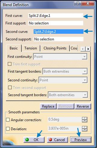
61 Pick the: Split tool >> Element to cut: >> Offset.1 >> Cutting elements >> Plane.1 >> OK. Pick the: Split tool >> Element to cut: >> Sweep.1 >> Cutting elements >> Plane.2 >> OK. 4.6 BLEND 2011 John Andrew Page 61 of 98


62 Above surface: File >> Save. 4.7 LOFT Sketch the 3-Point arc with a 2in radius in the yz plane. Pick the Plane tool >> Offset from plane >> Offset: >> 2in as shown above John Andrew Page 62 of 98


63 Sketch the second 3-Point arc with a 1.5in radius in the offset Plane.1 created above. Pick the Isometric View tool and sketch in the 3D view for clarity. Pick the Plane tool >> Offset from plane >> Offset: >> 2in as shown above. Sketch the 1in by 2in rectangle in the offset Plane John Andrew Page 63 of 98


64 Pick the: Multi-Sections Surface tool >> The Multi-Sections Surface Definition box will open. Pick Sections: 1, 2, and 3. The completed Loft. 5. FINITE ELEMENT ANALYSIS FEA All 3D solid parts begin with a sketch in the Sketcher Workbench. Make sure Num-Lock is off. Tools >> Options >> Units >> inches John Andrew Page 64 of 98

65 ANGLE BRACKET The angle bracket has a lip on each vertical edge representing fillet welds. The ring around the hole is the area of pressure applied by the bolt head and washer. Create the above angle bracket dimensions below. Select: Apply Material >> Aluminum The dimensions of the Angle Bracket are given in the above Catia drawing John Andrew Page 65 of 98


66 Use above drop-down menu: Start >> Analysis & Simulation >> Generative Structural Analysis New Analysis Case >> Static Analysis. Tree. Restraints toolbar 2011 John Andrew Page 66 of 98


67 The selected area on the lip of the vertical leg of the angle bracket duplicates a fillet weld. This weld area is Clamped above left and Right. The clamps are added to the tree under Restraints. Also, note that the clamps are red. They will be updated in the Analysis below John Andrew Page 67 of 98


68 The ring around the hole is the area of pressure applied by a bolt head with washer. Apply a distributed force to the angle bracket ring around the hole. Pick: Distributed Force >> Point on ring area as shown above. Update the Analysis: The boundary conditions set by the clamps and force are next updated John Andrew Page 68 of 98

69 Right click on the Energy tool in the tree, and select Update Sensor. Click OK through the warning, and you will see computation boxes appear John Andrew Page 69 of 98


70 The clamps and the load no longer are red after the above update. The green arrows show a uniform distributed force over the surface indicated. File >> Save John Andrew Page 70 of 98


71 Right click on Nodes and Elements, then select Mesh Visualization. The part is divided into many small tetrahedrons. STRESS AND DEFLECTIONS Now we will look at the results of the FEA. First click the Deformation tool John Andrew Page 71 of 98

72 The mesh deformed, according to the amount of load or force. Notice that the clamped welds have not moved. Also there is a Deformed Mesh entity under the Static Case Solution. The mesh size can be changed. In the tree, double click on OCTREE Tetrahedron Mesh. Change the size. Click OK. Note that the analysis tree objects have gone out of date. As before, right click on Nodes and Elements and select Mesh visualization. Click OK through the warning. You should now see a finer mesh. Now click the Von Mises Stress tool. This shows you a color coded stress plot across the mesh. Note also that the previous image (deformed mesh) is now deactivated John Andrew Page 72 of 98


73 Click on the Displacement tool. This shows displacement vectors, indicating the amount of displacement of the part due to the load. 6. MECHANISM DYNAMIC ANALYSIS MECHANISM-A solid model created with Catia is pictured above John Andrew Page 73 of 98

74 The speed and acceleration VS time graph for the block sliding on the guide rod above is not part of this assignment. Mechanism velocity and acceleration legend. MECHANISM-A part dimensions. ALL PART FILES IN AN ASSEMBLY MUST BE IN THE SAME FOLDER 2011 John Andrew Page 74 of 98


75 Tools >> Options >> Parameters and Measure >> Length >> Inch (in). Set length to inches. Start >> Assembly Design Right click on Product1 >> Properties. Edit Product1 to read MECHANISM-A as shown below John Andrew Page 75 of 98


76 Part Number has been changed to MECHANISM-A. Constraints Toolbar Insert >> Existing Component >> Click on MECHANISM-A below >> Browse Files >> Select the BASE ROD part. The BASE.1(BASE-ROD) part has been added to the tree below. Pick the Fix anchor tool and place it on the Base rod John Andrew Page 76 of 98


77 Insert >> Existing Component >> Click on MECHANISM-A above >> Browse Files >> Select BLOCK part. The Block part is inside the Guide Rod. Block. On the View toolbar pick Wire Frame to see the Pick the Manipulation tool on the Move toolbar. Pick the Y direction arrow on the Manipulation box. Pick the Guide Rod and drag it away from the Block as shown above John Andrew Page 77 of 98 Insert >> Existing Component >> Click on MECHANISM-A above >> Browse Files >> Select CRANK part.


78 All of the Catia parts were created at the same origin. On the Constraint toolbar pick the Coincidence Constraint tool. Pick-1 on Guide-Rod pivot pin surface >> Pick-2 in Crank hole as above John Andrew Page 78 of 98


79 Guide-Rod pivot pin and Crank hole axes are coincident. See Constraints added to the Tree above. View >> Compass turns the Compass on or off. Pick the red ball in the Compass and drag it to the Crank as above left. Pick Arc and release mouse button. Hold Ctrl key and rotate the Crank as shown above right John Andrew Page 79 of 98


80 Pick the red ball in the Compass and drag it to the xyz Axes in the bottom right corner of the display. Release the mouse button and the Compass will return automatically to the top right corner. Pick the Offset Constraint tool. Pick 1 >> Pick 2 part flat surfaces. Click one arrow to reverse direction if arrows do not point as above. Edit Offset >> 0in as shown above. Press keys: Ctrl + U to update the constraints John Andrew Page 80 of 98

81 The Offset constraint has been updated. Pick-1 arc >> Rotate the Crank. Drag the Compass red ball to the Crank as above. Ctrl + U to update. Pick the Offset Constraint tool. Pick 1 >> Pick 2 part flat surfaces. On the Constraint toolbar pick the Coincidence Constraint tool. Pick on the Guide Rod cylindrical surface >> Pick in the Block hole. Ctrl + U to update John Andrew Page 81 of 98


82 Use the Coincidence Constraint tool and the Offset Constraint tool to constrain the Crank and Conrod as shown above. In the tree below pick the top constraint, Shift Key, and bottom constraint. All constraint are selected this way. Pick Hide/Show to hide all constraints John Andrew Page 82 of 98


83 MECHANISM DYNAMIC ANALYSIS Start >> Digital Mockup >> DMU Kinematics 2011 John Andrew Page 83 of 98


84 Revolute Joint drop-down menu above on the Kinematics Joints toolbar shown below. Pick the: Assembly Constraint Conversion John Andrew Page 84 of 98
. The one degree of freedom must be removed to convert to a mechanism.")
85 Pick New Mechanism Select Auto Create Make sure Unresolved pairs are 0 / 4 If not: close Catia, re-open the above assembly, and check all restraints. The highlight by Catia indicates the mechanism is operational. Degrees of Freedom in the tree equal 1 (DOF=1). The one degree of freedom must be removed to convert to a mechanism. The Joint (BASE-ROD,CRANK.1) will be changed to Angle Driven John Andrew Page 85 of 98
 The CRANK has been converted into a Revolute.")


86 Double click on Revolute.2(BASE-ROD,CRANK.1) The CRANK has been converted into a Revolute. Pick Angle Driven. Edit Joint Limits to 0deg and 360deg as shown above. If the Information box above opens the mechanism will work. If not: close Catia, re-open the above assembly, and check all restraints John Andrew Page 86 of 98


87 Select Simulation on the Digital-Mock-Up (DMU) Generic Animation toolbar. Pick, Mechanism.1. Mechanism.1 is shown above. The Kinematics Simulation Mechanism box below will open next John Andrew Page 87 of 98


88 Slide the motion button above from left to right to rotate the Crank 360 degrees. Pick Insert to activate the Video player buttons as above left. Change the interpolation step from 1 to 0.02 seconds a shown above right. Pick the Play arrow and view the mechanism animation. Double-click the Loop Mode button above for continuous motion in one direction. Single-click the Loop Mode button for oscillating motion John Andrew Page 88 of 98


. Pick the Formula tool in the Knowledge toolbar.")
89 Select Simulation Player on the DMU Generic Animation toolbar. SIMULATING MECHANISM DYNAMIC CONDITIONS Time based physical laws. Pick the: Simulation with Laws tool. The information box above will open indicating that a relation (or formula) is needed between a parameter (Crank angle) and time (seconds). Pick the Formula tool in the Knowledge toolbar John Andrew Page 89 of 98


90 The Formulas: MECHANISM-A box will open. The objective is to plot the Crank Mechanism: Position, Velocity, and Acceleration VS Time. Pick Mechanism.1,DOF=0 in the tree. Only formulas associated with the Mechanism will now be displayed in the Formulas box John Andrew Page 90 of 98


91 Pick-1 >> Pick-2 >> OK. Pick: Time John Andrew Page 91 of 98
/(1s) The time is: (Mechanism.")
/(1s)*(Mechanism.1\KINTime).")
92 With Parameters and Time selected double click: Mechanism.1\KINTime The Crank angular velocity is: (360deg)/(1s) The time is: (Mechanism.1\KINTime) Therefore the Crank Angle = Crank angular velocity x Time Enter the right side of the equation: (360deg)/(1s)*(Mechanism.1\KINTime). Pick: OK and the box below will open John Andrew Page 92 of 98
 is the default.")


93 Check the units of distance. The International system of Units (ISU) is the default. If the Warning box opens with the words: Units are not homogeneous then change dimensions with: Tools >> Options >> Parameters and Measure >> Length >> Inch (in). The Law branch has been added. Pick: Speed and Acceleration on the DMU toolbar John Andrew Page 93 of 98


94 The Speed and Acceleration above box opens next. For Reference Product pick the BASE-ROD. Note: Speef-Acceleration.1 is added. For Point Selection pick a point on the BLOCK. Catia changes the name from BLOCK to Solid.1. Pick Simulation with Laws. Default time is 10 seconds and steps are John Andrew Page 94 of 98


95 Pick Activate sensors and change steps to 80. Time is 10 seconds. The Sensor box on page below will open. Pick the Browse button with3 dots. Change the time to 1 second. The steps have been changed to 80 and time to 1.0 second John Andrew Page 95 of 98

96 Pick: Mechanism.1\Joints\Cylindical.1\Length Speed-Acceleration.1\X_LinearSpeed Speed-Acceleration.1\X_LinearAcceleration 2011 John Andrew Page 96 of 98

97 Pick the Instantaneous Values tab in the Sensors box. DO NOT CLOSE THE SENSORS BOX. It will generate the plots below. Speed and acceleration VS time graph for the block sliding on the rod will be plotted with Catia as shown above John Andrew Page 97 of 98
98 Legend. END OF COURSE CONTENT 2011 John Andrew Page 98 of 98
Table of Contents. Dedication Preface. Chapter 1: Introduction to CATIA V5-6R2015. Chapter 2: Drawing Sketches in the Sketcher Workbench-I.
 Table of Contents Dedication Preface iii xvii Chapter 1: Introduction to CATIA V5-6R2015 Introduction to CATIA V5-6R2015 1-2 CATIA V5 Workbenches 1-2 System Requirements 1-4 Getting Started with CATIA
AutoCAD Inventor - Solid Modeling, Stress and Dynamic Analysis
 PDHonline Course G280 (15 PDH) AutoCAD Inventor - Solid Modeling, Stress and Dynamic Analysis Instructor: John R. Andrew, P.E. 2012 PDH Online PDH Center 5272 Meadow Estates Drive Fairfax, VA 22030-6658
Shaft Hanger - SolidWorks
 ME-430 INTRODUCTION TO COMPUTER AIDED DESIGN Shaft Hanger - SolidWorks BY: DR. HERLI SURJANHATA ASSIGNMENT Submit TWO isometric views of the Shaft Hanger with your report, 1. Shaded view of the trimetric
CATIA V5 Workbook Release V5-6R2013
 CATIA V5 Workbook Release V5-6R2013 Richard Cozzens SDC PUBLICATIONS Better Textbooks. Lower Prices. www.sdcpublications.com Powered by TCPDF (www.tcpdf.org) Visit the following websites to learn more
ME Week 2 Project 2 Flange Manifold Part
 1 Project 2 - Flange Manifold Part 1.1 Instructions This project focuses on additional sketching methods and sketching commands. Revolve and Work features are also introduced. The part being modeled is
Introduction to CATIA V5
 Introduction to CATIA V5 Release 17 (A Hands-On Tutorial Approach) Kirstie Plantenberg University of Detroit Mercy SDC PUBLICATIONS Schroff Development Corporation www.schroff.com Better Textbooks. Lower
Siemens NX11 tutorials. The angled part
 Siemens NX11 tutorials The angled part Adaptation to NX 11 from notes from a seminar Drive-to-trial organized by IBM and GDTech. This tutorial will help you design the mechanical presented in the figure
Using Siemens NX 11 Software. The connecting rod
 Using Siemens NX 11 Software The connecting rod Based on a Catia tutorial written by Loïc Stefanski. At the end of this manual, you should obtain the following part: 1 Introduction. Start NX 11 and open
SolidWorks 95 User s Guide
 SolidWorks 95 User s Guide Disclaimer: The following User Guide was extracted from SolidWorks 95 Help files and was not originally distributed in this format. All content 1995, SolidWorks Corporation Contents
Chapter 2. Drawing Sketches for Solid Models. Learning Objectives
 Chapter 2 Drawing Sketches for Solid Models Learning Objectives After completing this chapter, you will be able to: Start a new template file to draw sketches. Set up the sketching environment. Use various
SolidWorks Part I - Basic Tools SDC. Includes. Parts, Assemblies and Drawings. Paul Tran CSWE, CSWI
 SolidWorks 2015 Part I - Basic Tools Includes CSWA Preparation Material Parts, Assemblies and Drawings Paul Tran CSWE, CSWI SDC PUBLICATIONS Better Textbooks. Lower Prices. www.sdcpublications.com Powered
Quasi-static Contact Mechanics Problem
 Type of solver: ABAQUS CAE/Standard Quasi-static Contact Mechanics Problem Adapted from: ABAQUS v6.8 Online Documentation, Getting Started with ABAQUS: Interactive Edition C.1 Overview During the tutorial
Beginner s Guide to SolidWorks Alejandro Reyes, MSME Certified SolidWorks Professional and Instructor SDC PUBLICATIONS
 Beginner s Guide to SolidWorks 2008 Alejandro Reyes, MSME Certified SolidWorks Professional and Instructor SDC PUBLICATIONS Schroff Development Corporation www.schroff.com www.schroff-europe.com Part Modeling
Part Design Fundamentals
 Part Design Fundamentals 1 Course Presentation Objectives of the course In this course you will learn basic methods to create and modify solids features and parts Targeted audience New CATIA V5 Users 1
Lesson 4 Extrusions OBJECTIVES. Extrusions
 Lesson 4 Extrusions Figure 4.1 Clamp OBJECTIVES Create a feature using an Extruded protrusion Understand Setup and Environment settings Define and set a Material type Create and use Datum features Sketch
Quick Start for Autodesk Inventor
 Quick Start for Autodesk Inventor Autodesk Inventor Professional is a 3D mechanical design tool with powerful solid modeling capabilities and an intuitive interface. In this lesson, you use a typical workflow
Training Guide Basics
 Training Guide Basics 2014, Missler Software. 7, Rue du Bois Sauvage F-91055 Evry, FRANCE Web: www.topsolid.com E-mail: info@topsolid.com All rights reserved. TopSolid Design Basics This information is
Modeling Basic Mechanical Components #1 Tie-Wrap Clip
 Modeling Basic Mechanical Components #1 Tie-Wrap Clip This tutorial is about modeling simple and basic mechanical components with 3D Mechanical CAD programs, specifically one called Alibre Xpress, a freely
Lesson 6 2D Sketch Panel Tools
 Lesson 6 2D Sketch Panel Tools Inventor s Sketch Tool Bar contains tools for creating the basic geometry to create features and parts. On the surface, the Geometry tools look fairly standard: line, circle,
Engineering & Computer Graphics Workbook Using SOLIDWORKS
 Engineering & Computer Graphics Workbook Using SOLIDWORKS 2017 Ronald E. Barr Thomas J. Krueger Davor Juricic SDC PUBLICATIONS Better Textbooks. Lower Prices. www.sdcpublications.com Powered by TCPDF (www.tcpdf.org)
Engineering & Computer Graphics Workbook Using SolidWorks 2014
 Engineering & Computer Graphics Workbook Using SolidWorks 2014 Ronald E. Barr Thomas J. Krueger Davor Juricic SDC PUBLICATIONS Better Textbooks. Lower Prices. www.sdcpublications.com Powered by TCPDF (www.tcpdf.org)
Alternatively, the solid section can be made with open line sketch and adding thickness by Thicken Sketch.
 Sketcher All feature creation begins with two-dimensional drawing in the sketcher and then adding the third dimension in some way. The sketcher has many menus to help create various types of sketches.
AEROPLANE. Create a New Folder in your chosen location called Aeroplane. The four parts that make up the project will be saved here.
 AEROPLANE Prerequisite Knowledge Previous knowledge of the following commands is required to complete this lesson. Sketching (Line, Rectangle, Arc, Add Relations, Dimensioning), Extrude, Assemblies and
Using Siemens NX 11 Software. Sheet Metal Design - Casing
 Using Siemens NX 11 Software Sheet Metal Design - Casing Based on a YouTube NX tutorial 1. 1 https://www.youtube.com/watch?v=-siyi1vz87k A&M CAD in mechanical engineering 1 1 Introduction. Start NX 11
CATIA Instructor-led Live Online Training Program
 Course Outline Introduction & Understanding to CATIA Environment Introduction & Understanding to CATIA interface Starting new file Understand the Sketcher workbench of CATIA V5 Start a new file in the
Part 8: The Front Cover
 Part 8: The Front Cover 4 Earpiece cuts and housing Lens cut and housing Microphone cut and housing The front cover is similar to the back cover in that it is a shelled protrusion with screw posts extruding
Introduction to Autodesk Inventor for F1 in Schools (Australian Version)
") Introduction to Autodesk Inventor for F1 in Schools (Australian Version) F1 in Schools race car In this course you will be introduced to Autodesk Inventor, which is the centerpiece of Autodesk s Digital
Introduction to Autodesk Inventor for F1 in Schools (Australian Version) F1 in Schools race car In this course you will be introduced to Autodesk Inventor, which is the centerpiece of Autodesk s Digital
Feature-Based Modeling and Optional Advanced Modeling. ENGR 1182 SolidWorks 05
 Feature-Based Modeling and Optional Advanced Modeling ENGR 1182 SolidWorks 05 Today s Objectives Feature-Based Modeling (comprised of 2 sections as shown below) 1. Breaking it down into features Creating
Parametric Modeling with Creo Parametric 2.0
 Parametric Modeling with Creo Parametric 2.0 An Introduction to Creo Parametric 2.0 Randy H. Shih SDC PUBLICATIONS Schroff Development Corporation Better Textbooks. Lower Prices. www.sdcpublications.com
Module 1G: Creating a Circle-Based Cylindrical Sheet-metal Lateral Piece with an Overlaying Lateral Edge Seam And Dove-Tail Seams on the Top Edge
 Inventor (10) Module 1G: 1G- 1 Module 1G: Creating a Circle-Based Cylindrical Sheet-metal Lateral Piece with an Overlaying Lateral Edge Seam And Dove-Tail Seams on the Top Edge In Module 1A, we have explored
SOLIDWORKS 2015 and Engineering Graphics
 SOLIDWORKS 2015 and Engineering Graphics An Integrated Approach Randy H. Shih SDC PUBLICATIONS Better Textbooks. Lower Prices. www.sdcpublications.com Powered by TCPDF (www.tcpdf.org) Visit the following
Toothbrush Holder. A drawing of the sheet metal part will also be created.
 Prerequisite Knowledge Previous knowledge of the following commands is required to complete this lesson; Sketch (Line, Centerline, Circle, Add Relations, Smart Dimension,), Extrude Boss/Base, and Edit
Autodesk Inventor 2016
 Parametric Modeling with Autodesk Inventor 2016 Randy H. Shih SDC PUBLICATIONS Better Textbooks. Lower Prices. www.sdcpublications.com Powered by TCPDF (www.tcpdf.org) Visit the following websites to learn
Basic Features. In this lesson you will learn how to create basic CATIA features. Lesson Contents: CATIA V5 Fundamentals- Lesson 3: Basic Features
 Basic Features In this lesson you will learn how to create basic CATIA features. Lesson Contents: Case Study: Basic Features Design Intent Stages in the Process Determine a Suitable Base Feature Create
1. Open the Feature Modeling demo part file on the EEIC website. Ask student about which constraints needed to Fully Define.
 BLUE boxed notes are intended as aids to the lecturer RED boxed notes are comments that the lecturer could make Control + Click HERE to view enlarged IMAGE and Construction Strategy he following set of
Starting a 3D Modeling Part File
 1 How to Create a 3D Model and Corresponding 2D Drawing with Dimensions, GDT (Geometric Dimensioning and Tolerance) Symbols and Title Block in SolidWorks 2013-2014 By Edward Locke This tutorial will introduce
Below are the desired outcomes and usage competencies based on the completion of Project 4.
 Engineering Design with SolidWorks Project 4 Below are the desired outcomes and usage competencies based on the completion of Project 4. Project Desired Outcomes: An understanding of the customer s requirements
CREO.1 MODELING A BELT WHEEL
 CREO.1 MODELING A BELT WHEEL Figure 1: A belt wheel modeled in this exercise. Learning Targets In this exercise you will learn: Using symmetry when sketching Using pattern to copy features Using RMB when
Introduction to ANSYS DesignModeler
 Lecture 4 Planes and Sketches 14. 5 Release Introduction to ANSYS DesignModeler 2012 ANSYS, Inc. November 20, 2012 1 Release 14.5 Preprocessing Workflow Geometry Creation OR Geometry Import Geometry Operations
Veerapandian.K Mechanical Engg Vedharanyam A manual to mechanical designers How Solid works Works?
 Compiled by Veerapandian.K Mechanical Engg Vedharanyam-614 810 A manual to mechanical designers How Solid works Works? Solid works Overview Solid works main idea is user to create drawing directly in 3D
and Engineering Graphics
 SOLIDWORKS 2018 and Engineering Graphics An Integrated Approach Randy H. Shih SDC PUBLICATIONS Better Textbooks. Lower Prices. www.sdcpublications.com Powered by TCPDF (www.tcpdf.org) Visit the following
for Solidworks TRAINING GUIDE LESSON-9-CAD
 for Solidworks TRAINING GUIDE LESSON-9-CAD Mastercam for SolidWorks Training Guide Objectives You will create the geometry for SolidWorks-Lesson-9 using SolidWorks 3D CAD software. You will be working
Education Curriculum Combined Specialist
 Education Curriculum Combined Specialist Invest your time in imagining next generation designs. Here s what we will teach you to give shape to your imagination. CATIA Combined Specialist Course CATIA Mechanical
Introduction to Autodesk Inventor User Interface Student Manual MODEL WINDOW
 Emmett Wemp EDTECH 503 Introduction to Autodesk Inventor User Interface Fill in the blanks of the different tools available in the user interface of Autodesk Inventor as your instructor discusses them.
< Then click on this icon on the vertical tool bar that pops up on the left side.
 Pipe Cavity Tutorial Introduction The CADMAX Solid Master Tutorial is a great way to learn about the benefits of feature-based parametric solid modeling with CADMAX. We have assembled several typical parts
Product Modelling in Solid Works
 Product Modelling in Solid Works In the following exercise you will use solid works to construct the computer mouse shown opposite. In this exercise you will use a number of advanced features to achieve
Introducing SolidWorks
 Introducing SolidWorks SAAST Robotics 2008 SolidWorks Software Visually-based 3-D Mechanical design software Engineers and Designers use it to: Quickly sketch out ideas Experiment with features, dimensions
Engineering Technology
 Engineering Technology Introduction to Parametric Modelling Engineering Technology 1 See Saw Exercise Part 1 Base Commands used New Part This lesson includes Sketching, Extruded Boss/Base, Hole Wizard,
Explanation of buttons used for sketching in Unigraphics
 Explanation of buttons used for sketching in Unigraphics Sketcher Tool Bar Finish Sketch is for exiting the Sketcher Task Environment. Sketch Name is the name of the current active sketch. You can also
From the above fig. After sketching the path and profile select the sweep command First select the profile from property manager tree And then select
 Chapter 5 In sweep command there is a) Two sketch profiles b) Two path c) One sketch profile and one path The sweep profile is used to create threads springs circular things and difficult geometry. For
CATIA V5R20. for Engineers & Designers
 CATIA V5R20 for Engineers & Designers Contributing Authors Sham Tickoo Professor Department of Mechanical Engineering Technology Purdue University Calumet Hammond, Indiana, USA D.Saravanan Sr. CAD Engineer
Digital Camera Exercise
 Commands Used New Part This lesson includes Sketching, Extruded Boss/Base, Extruded Cut, Fillet, Chamfer and Text. Click File, New on the standard toolbar. Select Part from the New SolidWorks Document
Generative Drafting (ISO)
") CATIA Training Foils Generative Drafting (ISO) Version 5 Release 8 January 2002 EDU-CAT-E-GDRI-FF-V5R8 1 Table of Contents (1/2) 1. Introduction to Generative Drafting Generative Drafting Workbench Presentation
CATIA Training Foils Generative Drafting (ISO) Version 5 Release 8 January 2002 EDU-CAT-E-GDRI-FF-V5R8 1 Table of Contents (1/2) 1. Introduction to Generative Drafting Generative Drafting Workbench Presentation
Introduction to SolidWorks Introduction to SolidWorks
 Introduction to SolidWorks Introduction to SolidWorks SolidWorks is a powerful 3D modeling program. The models it produces can be used in a number of ways to simulate the behaviour of a real part or assembly
Modeling an Airframe Tutorial
 EAA SOLIDWORKS University p 1/11 Difficulty: Intermediate Time: 1 hour As an Intermediate Tutorial, it is assumed that you have completed the Quick Start Tutorial and know how to sketch in 2D and 3D. If
UNIT 11: Revolved and Extruded Shapes
 UNIT 11: Revolved and Extruded Shapes In addition to basic geometric shapes and importing of three-dimensional STL files, SOLIDCast allows you to create three-dimensional shapes that are formed by revolving
Table of Contents. Lesson 1 Getting Started
 NX Lesson 1 Getting Started Pre-reqs/Technical Skills Basic computer use Expectations Read lesson material Implement steps in software while reading through lesson material Complete quiz on Blackboard
Lesson 4 Holes and Rounds
 Lesson 4 Holes and Rounds 111 Figure 4.1 Breaker OBJECTIVES Sketch arcs in sections Create a straight hole through a part Complete a Sketched hole Understand the Hole Tool Use Info to extract information
Parametric Modeling. with. Autodesk Inventor Randy H. Shih. Oregon Institute of Technology SDC
 Parametric Modeling with Autodesk Inventor 2009 Randy H. Shih Oregon Institute of Technology SDC PUBLICATIONS Schroff Development Corporation www.schroff.com Better Textbooks. Lower Prices. iii Table of
Inventor-Parts-Tutorial By: Dor Ashur
 Inventor-Parts-Tutorial By: Dor Ashur For Assignment: http://www.maelabs.ucsd.edu/mae3/assignments/cad/inventor_parts.pdf Open Autodesk Inventor: Start-> All Programs -> Autodesk -> Autodesk Inventor 2010
SolidWize. Online SolidWorks Training. Simple Sweep: Head Scratcher
 SolidWize Online SolidWorks Training Simple Sweep: Head Scratcher Step 1: Creating the Handle: Sketch Using Inches as the unit create a sketch on the Front plane. Start with the sketch shown below: Create
1.6.7 Add Arc Length Dimension Modify Dimension Value Check the Sketch Curve Connectivity
 Contents 2D Sketch... 1 1.1 2D Sketch Introduction... 1 1.1.1 2D Sketch... 1 1.1.2 Basic Setting of 2D Sketch... 2 1.1.3 Exit 2D Sketch... 4 1.2 Draw Common Geometry... 5 2.2.1 Points... 5 2.2.2 Lines
1. Create a 2D sketch 2. Create geometry in a sketch 3. Use constraints to position geometry 4. Use dimensions to set the size of geometry
 2.1: Sketching Many features that you create in Fusion 360 start with a 2D sketch. In order to create intelligent and predictable designs, a good understanding of how to create sketches and how to apply
SDC. SolidWorks Tutorial 2001Plus. A Competency Project Based Approach Utilizing 3D Solid Modeling. David C. Planchard & Marie P.
 2001Plus A Competency Project Based Approach Utilizing 3D Solid Modeling David C. Planchard & Marie P. Planchard SDC PUBLICATIONS www.schroff.com www.schroff-europe.com Project 2 Below are the desired
User Guide V10 SP1 Addendum
 Alibre Design User Guide V10 SP1 Addendum Copyrights Information in this document is subject to change without notice. The software described in this document is furnished under a license agreement or
TUTORIAL 4: Combined Axial and Bending Problem Sketch Path Sweep Initial Project Space Setup Static Structural ANSYS
 TUTORIAL 4: Combined Axial and Bending Problem In this tutorial you will learn how to draw a bar that has bends along its length and therefore will have both axial and bending stresses acting on cross-sections
M TE S Y S LT U A S S A
 Dress-Up Features In this lesson you will learn how to place dress-up features on parts. Lesson Contents: Case Study: Timing Chain Cover Design Intent Stages in the Process Apply a Draft Create a Stiffener
Designing in Context. In this lesson, you will learn how to create contextual parts driven by the skeleton method.
 Designing in Context In this lesson, you will learn how to create contextual parts driven by the skeleton method. Lesson Contents: Case Study: Designing in context Design Intent Stages in the Process Clarify
Introduction to Sheet Metal Features SolidWorks 2009
 SolidWorks 2009 Table of Contents Introduction to Sheet Metal Features Base Flange Method Magazine File.. 3 Envelopment & Development of Surfaces.. 14 Development of Transition Pieces.. 23 Conversion to
Graz University of Technology CATIA V5. Basic Training. CAx in Automotive and Engine Technology Dipl.-Ing. Dr.techn.
 CATIA V5 Basic Training CAx in Automotive and Engine Technology 313.067 Dipl.-Ing. Dr.techn. Michael Lang Preface The present script includes an introduction of the main features in the 3D design software
Introduction to Circular Pattern Flower Pot
 Prerequisite Knowledge Previous knowledge of the sketching commands Line, Circle, Add Relations, Smart Dimension is required to complete this lesson. Previous examples of Revolved Boss/Base, Cut Extrude,
Essentials of SOLIDWORKS 2015 (4+ Days) * Ve-I Bonus! * File Management + SimulationXpress
 * Ve-I Bonus! * File Management + SimulationXpress") Essentials of SOLIDWORKS 2015 (4+ Days) * Ve-I Bonus! * File Management + SimulationXpress Overview What is SOLIDWORKS? Interface Tour View Manipulation Provides some background info on the SOLIDWORKS
Essentials of SOLIDWORKS 2015 (4+ Days) * Ve-I Bonus! * File Management + SimulationXpress Overview What is SOLIDWORKS? Interface Tour View Manipulation Provides some background info on the SOLIDWORKS
Creo Parametric 4.0 Basic Design
 Creo Parametric 4.0 Basic Design Contents Table of Contents Introduction...1 Objective of This Textbook...1 Textbook Outline...2 Textbook Conventions...3 Exercise Files...3 System Configuration...4 Notes
SOLIDWORKS 2016 Advanced Techniques
 SOLIDWORKS 2016 Advanced Techniques Mastering Parts, Surfaces, Sheet Metal, SimulationXpress, Top Down Assemblies, Core & Cavity Molds Paul Tran CSWE, CSWI SDC PUBLICATIONS Better Textbooks. Lower Prices.
with Creo Parametric 4.0
 Parametric Modeling with Creo Parametric 4.0 An Introduction to Creo Parametric 4.0 NEW Contains a new chapter on 3D Printing Randy H. Shih SDC PUBLICATIONS Better Textbooks. Lower Prices. www.sdcpublications.com
Made Easy. Jason Pancoast Engineering Manager
 3D Sketching Made Easy Jason Pancoast Engineering Manager Today I have taught you to sketch in 3D. It s as easy as counting ONE, TWO, FIVE...er...THREE! When your sketch only lives in Y and in X, Adding
SolidWorks 2013 Part I - Basic Tools
 SolidWorks 2013 Part I - Basic Tools Parts, Assemblies and Drawings Paul Tran CSWE, CSWI Supplemental Files SDC PUBLICATIONS Schroff Development Corporation Better Textbooks. Lower Prices. www.sdcpublications.com
Creo Parametric Primer
 PTC Creo Parametric - Primer Student and Academic Editions 02 Helpful hints are enclosed in red brackets or round bubbles like this one! Creo Parametric Primer THIS VERSION OF THE CREO PRIMER HAS BEEN
Part 2: Earpiece. Insert Protrusion (Internal Sketch) Hole Patterns Getting Started with Pro/ENGINEER Wildfire. Round extrusion.
 Hole Patterns Getting Started with Pro/ENGINEER Wildfire. Round extrusion.") Part 2: Earpiece 4 Round extrusion Radial pattern Chamfered edge To create this part, you'll use some of the same extrusion techniques you used in the lens part. The only difference in this part is that
Part 2: Earpiece 4 Round extrusion Radial pattern Chamfered edge To create this part, you'll use some of the same extrusion techniques you used in the lens part. The only difference in this part is that
Creo Revolve Tutorial
 Creo Revolve Tutorial Setup 1. Open Creo Parametric Note: Refer back to the Creo Extrude Tutorial for references and screen shots of the Creo layout 2. Set Working Directory a. From the Model Tree navigate
Evaluation Chapter by CADArtifex
 The premium provider of learning products and solutions www.cadartifex.com EVALUATION CHAPTER 2 Drawing Sketches with SOLIDWORKS In this chapter: Invoking the Part Modeling Environment Invoking the Sketching
SolidWorks 2014 Part I - Basic Tools
 SolidWorks 2014 Part I - Basic Tools Parts, Assemblies and Drawings Paul Tran CSWE, CSWI SDC PUBLICATIONS Better Textbooks. Lower Prices. www.sdcpublications.com Powered by TCPDF (www.tcpdf.org) Visit
Creo Parametric 2.0: Introduction to Solid Modeling. Creo Parametric 2.0: Introduction to Solid Modeling
 Creo Parametric 2.0: Introduction to Solid Modeling 1 2 Part 1 Class Files... xiii Chapter 1 Introduction to Creo Parametric... 1-1 1.1 Solid Modeling... 1-4 1.2 Creo Parametric Fundamentals... 1-6 Feature-Based...
Introduction to Parametric Modeling AEROPLANE. Design & Communication Graphics 1
 AEROPLANE Design & Communication Graphics 1 Object Analysis sheet Design & Communication Graphics 2 Aeroplane Assembly The part files for this assembly are saved in the folder titled Aeroplane. Open an
Engineering Design. with SolidWorks A Step-by-Step Project Based Approach Utilizing 3D Solid Modeling
 INSIDE: MultiMedia CD An audio/visual presentation of the tutorial projects Engineering Design with SolidWorks 2010 A Step-by-Step Project Based Approach Utilizing 3D Solid Modeling Introductory Level
Part Design. Sketcher - Basic 1 13,0600,1488,1586(SP6)
") Part Design Sketcher - Basic 1 13,0600,1488,1586(SP6) In this exercise, we will learn the foundation of the Sketcher and its basic functions. The Sketcher is a tool used to create two-dimensional (2D)
Part Design Sketcher - Basic 1 13,0600,1488,1586(SP6) In this exercise, we will learn the foundation of the Sketcher and its basic functions. The Sketcher is a tool used to create two-dimensional (2D)
Engineering Design with SolidWorks A Step-by-Step Project Based Approach Utilizing 3D Solid Modeling. David C. Planchard & Marie P.
 Engineering Design with SolidWorks 2003 A Step-by-Step Project Based Approach Utilizing 3D Solid Modeling David C. Planchard & Marie P. Planchard SDC PUBLICATIONS www.schroff.com www.schroff-europe.com
Rotational Patterns of Sketched Features Using Datum Planes On-The-Fly
 Rotational Patterns of Sketched Features Using Datum Planes On-The-Fly Patterning a sketched feature (such as a slot, rib, square, etc.,) requires a slightly different technique. Why can t we create a
Revit Structure 2012 Basics:
 SUPPLEMENTAL FILES ON CD Revit Structure 2012 Basics: Framing and Documentation Elise Moss autodesk authorized publisher SDC PUBLICATIONS www.sdcpublications.com Schroff Development Corporation Structural
Software Development & Education Center NX 8.5 (CAD CAM CAE)
") Software Development & Education Center NX 8.5 (CAD CAM CAE) Detailed Curriculum Overview Intended Audience Course Objectives Prerequisites How to Use This Course Class Standards Part File Naming Seed
Software Development & Education Center NX 8.5 (CAD CAM CAE) Detailed Curriculum Overview Intended Audience Course Objectives Prerequisites How to Use This Course Class Standards Part File Naming Seed
Module 1C: Adding Dovetail Seams to Curved Edges on A Flat Sheet-Metal Piece
 1 Module 1C: Adding Dovetail Seams to Curved Edges on A Flat Sheet-Metal Piece In this Module, we will explore the method of adding dovetail seams to curved edges such as the circumferential edge of a
SolidWorks Design & Technology
 SolidWorks Design & Technology Training Course at PHSG Ex 5. Lego man Working with part files 8mm At first glance the Lego man looks complicated but I hope you will see that if you approach a project one
Getting Started. Chapter. Objectives
 Chapter 1 Getting Started Autodesk Inventor has a context-sensitive user interface that provides you with the tools relevant to the tasks being performed. A comprehensive online help and tutorial system
Generative Drafting Overview What's New Getting Started User Tasks
 Generative Drafting Overview Conventions What's New Getting Started Defining the Drawing Sheet Part Drawing Opening a Part Creating a Front View Creating a Projection View Creating a Section View Creating
Assemble This! [Part 1]
![Assemble This! [Part 1]](/thumbs/74/69963588.jpg "Assemble This! [Part 1]") 11/30/2006-3:00 pm - 4:30 pm Room:Marcello - 4401 (MSD Campus) Assemble This! [Part 1] Alan Kalameja - Trident Technical College and Kevin Robinson (Assistant); Patrik Chartrand (Assistant) MA34-1L This
11/30/2006-3:00 pm - 4:30 pm Room:Marcello - 4401 (MSD Campus) Assemble This! [Part 1] Alan Kalameja - Trident Technical College and Kevin Robinson (Assistant); Patrik Chartrand (Assistant) MA34-1L This
Module 1E: Parallel-Line Flat Pattern Development of Sheet- Metal Folded Model Wrapping the 3D Space of An Oblique Circular Cylinder
 Inventor (10) Module 1E: 1E- 1 Module 1E: Parallel-Line Flat Pattern Development of Sheet- Metal Folded Model Wrapping the 3D Space of An Oblique Circular Cylinder In this Module, we will explore the topic
Activity 1 Modeling a Plastic Part
 Activity 1 Modeling a Plastic Part In this activity, you will model a plastic part. When completed, your plastic part should look like the following two illustrations. While building this model, take time
Teach Yourself UG NX Step-by-Step
 Teach Yourself UG NX Step-by-Step By Hui Zhang Ph.D., P.Eng. www.geocities.com/zhanghui1998 Table of Contents Chapter 1 Introduction... 1 1.1 UG NX User Interface... 1 1.2 Solid Modeling Fundamentals...