Welding Symbols. Faculty of Engineering Mechanical Dept.
|
|
|
- Godfrey Shelton
- 5 years ago
- Views:
Transcription


1 Welding Symbols Faculty of Engineering Mechanical Dept.
2 Objectives 1. Know the name of the AWS & ISO standards for welding symbols 2. List the eight elements that may be found on a welding symbol 3. List the basic weld symbols 4. List the supplementary symbols 5. Identify the applications of the different weld symbols
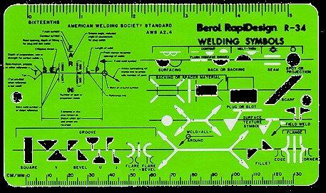
3 Weld symbols on drawings A method of transferring information from the design office to the workshop is: Please weld here The above information does not tell us much about the wishes of the designer. We obviously need some sort of code which would be understood by everyone. Most countries have their own standards for symbols. Some of them are AWS A2.4 & BS EN (ISO 2553)
4 AWS Standard Weld symbol Graphic symbol that indicates weld required Welding symbol Following eight elements: Reference line (required) Arrow (required) Basic weld symbols Dimensions and other data Supplementary symbols Finish symbols Tail Other specifications

5 Welding Symbol Components

6 Welding Symbol Components

7 Welding Symbol Components
8 Weld symbols on drawings Advantages of symbolic representation: simple and quick plotting on the drawing does not over-burden the drawing no need for additional view gives all necessary indications regarding the specific joint to be obtained Disadvantages of symbolic representation: used only for usual joints requires training for properly understanding of symbols
9 Dimensions Convention of dimensions In most standards the cross sectional dimensions are given to the left side of the symbol, and all linear dimensions are give on the right side BS EN ISO a = Design throat thickness s = Depth of Penetration, Throat thickness z = Leg length (min material thickness) AWS A2.4 In a fillet weld, the size of the weld is the leg length In a butt weld, the size of the weld is based on the depth of the joint preparation
10 Weld symbols on drawings Joints in drawings may be indicated: by detailed sketches, showing every dimension by symbolic representation
11 Elementary Weld Symbols Square Groove Weld Single V Groove Weld
12 Elementary Weld Symbols Single Bevel Groove Weld Single V Groove Weld with Broad Root Face
13 Elementary Weld Symbols Single Bevel Groove Weld with Broad Root Face Single U Groove Weld
14 Elementary Weld Symbols Single J Groove Weld Backing Weld
15 Elementary Weld Symbols Fillet Weld Plug / Slot Weld
16 Elementary Weld Symbols Spot Weld Seam Weld
17 Elementary Weld Symbols Edge Weld Surfacing
18 SUPPLEMENTARY SYMBOLS Weld Profile Flat Convex Concave
19 SUPPLEMENTARY SYMBOLS M MR Toes blended smoothly Permanent Backing Strip Removable Backing Strip
20 SUPPLEMENTARY SYMBOLS Peripheral Welds
21 Basic Weld Symbols AWS
22 Basic Weld Symbols AWS
23 Welding Symbols AWS
24 ISO 2553 / BS EN of 691 Plug weld Square Butt weld Resistance spot weld Steep flanked Single-V Butt Resistance seam weld Surfacing
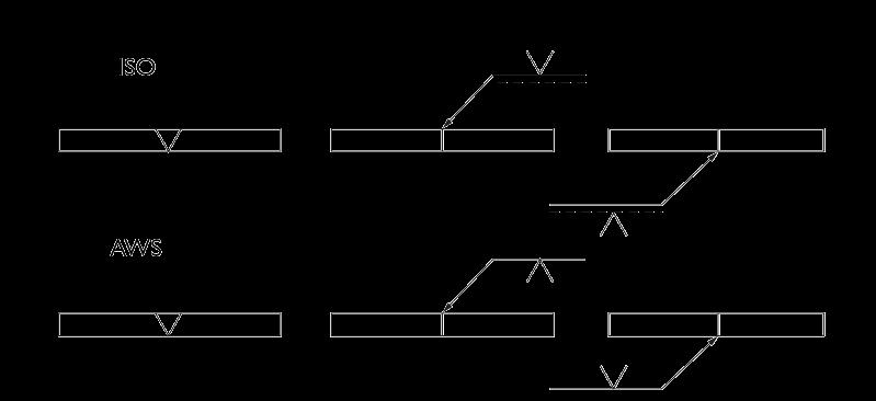
25 ISO & AWS
26 Arrow Line (BS EN ISO & AWS A2.4): Convention of the arrow line: Shall touch the joint intersection Shall not be parallel to the drawing Shall point towards a single plate preparation (when only one plate has preparation)
27 Reference Line (AWS A2.4) Convention of the reference line: Shall touch the arrow line Shall be parallel to the bottom of the drawing
28 Reference Line (BS EN ISO 22553) Convention of the reference line: Shall touch the arrow line Shall be parallel to the bottom of the drawing There shall be a further broken identification line above or beneath the reference line (Not necessary where the weld is symmetrical!) or
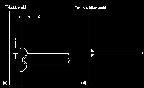
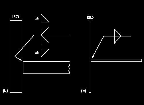
29 Double side weld symbols (BS EN ISO & AWS A2.4) Convention of the double side weld symbols: Representation of welds done from both sides of the joint intersection, touched by the arrow head Fillet weld Double bevel Double J Double V Double U

30 ISO 2553 / BS EN of 691 M M R Single-V Butt with permanent backing strip Single-U Butt with removable backing strip Single-V Butt flush cap Single-U Butt with sealing run
31 ISO 2553 / BS EN of 691 Single-bevel butt Double-bevel butt Single-bevel butt Single-J butt
32 ISO 2553 / BS EN s Partial penetration single-v butt S indicates the depth of penetration
33 ISO 2553 / BS EN of 691 a = Design throat thickness s = Depth of Penetration, Throat thickness z = Leg length(min material thickness) a = (0.7 x z) z 6 z a s a 4 4mm Design throat s 6 6mm leg 6mm Actual throat
34 ISO 2553 / BS EN of 691 Arrow side Arrow side
35 ISO 2553 / BS EN of 691 s6 6mm fillet weld Other side s6 Other side
36 ISO 2553 / BS EN of 691 n = number of weld elements l = length of each weld element (e) = distance between each weld element n x l (e) 2 x 40 (50) 3 x 40 (50) 111 Welds to be staggered Process
37 ISO 2553 / BS EN All dimensions in mm z5 z6 3 x 80 (90) 3 x 80 (90)
 3 x 80 (90) 6 6 80 80 80 8 90 90 90 8")
38 ISO 2553 / BS EN All dimensions in mm z8 z6 3 x 80 (90) 3 x 80 (90)
39 Supplementary symbols (BS EN ISO & AWS A2.4) Convention of supplementary symbols Supplementary information such as welding process, weld profile, NDT and any special instructions Site Weld Toes to be ground smoothly (BS EN only) Concave or Convex Weld all round
40 Supplementary symbols (BS EN ISO & AWS A2.4) Convention of supplementary symbols Supplementary information such as welding process, weld profile, NDT and any special instructions Ground flush MR Removable backing strip M Permanent backing strip 111 Welding process numerical BS EN Further supplementary information, such as WPS number, or NDT may be placed in the fish tail
41 ISO 2553 / BS EN of 691 a b c d


42 ISO 2553 / BS EN Mitre Convex Concave Toes shall be blended
43 ISO 2553 / BS EN Complimentary Symbols Field weld (site weld) Welding to be carried out all round component (peripheral weld) NDT WPS The component requires NDT inspection Additional information, the reference document is included in the box
44 ISO 2553 / BS EN of 691 Numerical Values for Welding Processes: 111: MMA welding with covered electrode 121: Sub-arc welding with wire electrode 131: MIG welding with inert gas shield 135: MAG welding with non-inert gas shield 136: Flux core arc welding 141: TIG welding 311: Oxy-acetylene welding 72: Electro-slag welding 15: Plasma arc welding

45 AWS A2.4 Welding Symbols
46 AWS Welding Symbols Depth of Bevel Root Opening 1 (1-1/8) 1/8 60 o Effective Throat Groove Angle
47 AWS Welding Symbols Welding Process 1 (1-1/8) 1/8 60 o GSFCAW GMAW GTAW SAW
48 AWS Welding Symbols Welds to be staggered SMAW Process
49 AWS Welding Symbols Sequence of Operations 3rd Operation 2nd Operation 1 (1-1/8) 1st Operation 1/8 60 o FCAW
50 AWS Welding Symbols Sequence of Operations MT MT RT 1 (1-1/8) 1/8 60 o FCAW
51 Fillet Welds and Symbol Fillet weld triangular-shaped weld placed on the joint Fillet weld symbol triangular in shape Vertical line of fillet weld symbol always drawn to left of symbol Size always shown to left of symbol and length to right of symbol No length given, then weld should run full length of joint
52 AWS Welding Symbols 52 of 691 Dimensions- Leg Length 6/8 6 leg on member A Member A 6 8 Member B
53 AWS A 2.4 rules-example 10 3 x 50 (70)
54 Fillet welds Fillet weld dimensions according AWS A x 8 5 leg on vertical member
55 Intermittent fillet welds Chain intermittent fillet weld pitch (e) length (l) z z z l - e l - e Symbol to AWS A2.4
56 Intermittent fillet welds Staggered intermittent fillet weld pitch (e) e/2 length (l) z Symbol to AWS A2.4 z z l - e l - e

57 Examples: Fillet Welds on T-Joints
58

59 Example: Fillet Weld Length and Pitch Indications

60 Weld-All-Around Symbol Used when weld is to extend all way around joint or series of connected joints Symbol: circle viewable at junction of reference line and arrow
61 Groove Welds Seven types of groove welds and symbols to represent them Square V Bevel U J Flare-V Flare-bevel Symbols take the shape of the groove the weld is to be placed in.
62 Groove Welds Place in a joint Used to make butt joints, but can be used to make other types of joints Double bevel One of joint members has bevel on both sides and joint is to be welded from both sides V shape

63 V-groove Weld on Butt Joint

64 Double V-groove Weld on Butt Joint


65 Contour Symbol and Letters Which Indicate Finishing Method


66
Basic Welding Symbols and Their Location Significance
 Basic Welding Symbols and Their Location Significance Objectives After completing this chapter, the student should be able to: Understand the basics of welding symbols List the major parts of a welding
Basic terms of a welded joint are shown in Fig and the five basic types of joints are shown in Fig
 Welding is an effective method of making permanent joints between two or more metal parts. Cast iron, steel and its alloys, brass and copper are the metals that may be welded easily. Production of leak
Fig. 9 Different weld positions. There are five basic types of common joints. They are
 c) Vertical - On the wall d) Horizontal - On the wall Fig. 9 Different weld positions 7.0 TYPES OF JOINTS There are five basic types of common joints. They are Butt joint Lap joint T joint Corner joint,
Welding 2 go. alhuzaim_af [Type the company name] 8/2/2012
![Welding 2 go. alhuzaim_af [Type the company name] 8/2/2012](/thumbs/86/93471492.jpg "Welding 2 go. alhuzaim_af [Type the company name] 8/2/2012") 2012 Welding 2 go alhuzaim_af [Type the company name] 8/2/2012 One must try by doing the thing; for though you think you know it, you have no certainty until you try. - Sophocles 2 I would like to express
2012 Welding 2 go alhuzaim_af [Type the company name] 8/2/2012 One must try by doing the thing; for though you think you know it, you have no certainty until you try. - Sophocles 2 I would like to express
Standards and Competencies
 Skill Performance The skill performance assessment includes the completion of a metal project and a demonstration of the ability to weld carbon steel, aluminum or stainless-steel project in various using
Trade of Metal Fabrication. Module 3: Plate Fabrication Unit 12: Duct Sections Phase 2
 Trade of Metal Fabrication Module 3: Plate Fabrication Unit 12: Duct Sections Phase 2 Table of Contents List of Figures... 4 List of Tables... 5 Document Release History... 6 Module 3 Plate Fabrication...
Deciphering Weld Symbols - MillerWelds
 Deciphering 91 Weld Shares Symbols When welds are specified on engineering and fabrication drawings, a cryptic set of symbols is used as a sort of shorthand for describing the type of weld, its size, and
Welding symbols on drawings
 Welding symbols on drawings Related titles from Woodhead s materials engineering list: Welded design theory and practice (ISBN 1 85573 537 7) A thoroughly practical text, but with sufficient theory to
Svetskommissionen. Review of SS-EN ISO 2553:2014
 Svetskommissionen Review of SS-EN ISO 2553:2014 Risks with the new standard EN ISO 2553:2014 EN ISO 2553:2014 EN ISO 2553 EN-ISO 2553:2014 supersede ISO 2553:1994 EN ISO 2553:2014 recognizes two different
Welding symbols on drawings
 Welding symbols on drawings Related titles from Woodhead s materials engineering list: Welded design theory and practice (ISBN 1 85573 537 7) A thoroughly practical text, but with sufficient theory to
Pro/ENGINEER. WELDING SYMBOLS LIBRARY Catalog. Parametric Technology Corporation
 Pro/ENGINEER WELDING SYMBOLS LIBRARY Catalog Parametric Technology Corporation Contents Chapter 1: ANSI Generic Welding Symbols 1-1 Welding Symbols Library... 1-2 Controlling Symbol and Text Size... 1-2
WELDING FABRICATION NYS
 WELDING FABRICATION NYS PURPOSE To evaluate each contestant s preparation for employment and to recognize outstanding students for excellence and professionalism in the field of fabrication. ELIGIBILITY
2019 Welding- Individuals Secondary & Post-secondary
 09 Welding- Individuals Secondary & Post-secondary To Instructors & Contestants: Welcome to the 09 Welding SkillsUSA competition. Everyone involved with this program is very excited to see you display
WELDING FABRICATION. First, download and review the General Regulations at: updates.skillsusa.org.
 WELDING FABRICATION PURPOSE To evaluate each contestant s preparation for employment and to recognize outstanding students for excellence and professionalism in the field of fabrication. First, download
SMAW LESSON #1: Initiating and maintaining an arc using the scratch start method
 SMAW LESSON #1: Initiating and maintaining an arc using the scratch start method OBJECTIVE: Upon completion of this lesson the learner will be able to strike and maintain an arc using SMAW on steel plate
Section I. PRINT READING
 Welding.Com Welding Symbols - welding, equipment, supply, mig, tig, education, cours... Page 1 of 31 Friday March 2, 2007 Contact us at Welding.Com Advertise Here! Message Board Welding Schools Revolutionary
Welding Qualification/Certification
 Welding Qualification/Certification 9/14/2011 1 Index Page Number Pre-testing Procedure 3 Bend Test Procedure Coupons 4 Drawing for cutting Coupons and Back strap removal 5-9 Preparation and Testing Procedure
WELDER ONTARIO PRACTICAL ASSESSMENT
 WELDER ONTARIO PRACTICAL ASSESSMENT 2017. 11 Please read all the information provided before you start the assessment. This assessment tests four welding processes (FCAW, SMAW, GMAW, GTAW), five plate
Bolted Joint Types Grip Washer
 Structural Bolting The Research Council on Structural Connections (RCSC) prepares specifications and documents related to structural connections RCSC s Specification for Structural Joints Using ASTM A325
Exercises in Welding Process and Equipment --- Part 3: Power-source and Equipment ---
 JICA_OHJI Exercises in Welding Process and Equipment --- Part 3: Power-source and Equipment --- Takayoshi OHJI Professor Emeritus, Osaka University Dr. of Engineering VIRTUAL WELD CO.,LTD t-ohji@alvec.co.jp
STEEL REPAIR PROCEDURES OPERATIONS MANUAL
 STEEL REPAIR PROCEDURES OPERATIONS MANUAL New York State Department of Transportation Operations Division Office of Transportation Maintenance March, 2009 This page left intentionally blank. 2 FOREWORD
Blueprint Reading Basics For Welding Fabrication
 Blueprint Reading Basics For Welding Fabrication 9/14/2011 1 Definitions of Lines Lines are the basic communication tool used in blueprints. Listed below are examples of the most common lines used in blueprints
Make a Safe. Description. Lesson Objectives. Assumptions. Terminology
 Youth Explore Trades Skills Make a Safe Description Welding is a vast area in the metalworking field and a widely used joining process for metal. In this activity plan students will learn how to MIG weld
COASTAL BEND COLLEGE WELDING SYLLABUS (Revised 8/10) Introduction to Blueprint Reading for Welders
 Introduction to Blueprint Reading for Welders") COASTAL BEND COLLEGE WELDING SYLLABUS (Revised 8/10) WLDG 1313: Introduction to Blueprint Reading for Welders Semester Hours: 3 Textbooks: Blueprint Reading For Welders, by A.E. Bennett & Louis J. Siy,
COASTAL BEND COLLEGE WELDING SYLLABUS (Revised 8/10) WLDG 1313: Introduction to Blueprint Reading for Welders Semester Hours: 3 Textbooks: Blueprint Reading For Welders, by A.E. Bennett & Louis J. Siy,
These introduction pages will give a
 HGG s Profiling Shapes Welcome to the world of Profiling Shapes. HGG s shapes have several distinct advantages as minimum grinding, easy fitting and optimised weld preparation for rapid welding and strong
Plating. Level 3 - International Competence: Engineering-Construction (Blue Card)
") Plating Level 3 - International Competence: Engineering-Construction (Blue Card) OCCUPATION PROFILE PLATER Platers within the engineering construction industry prepare steel and/or other metal plates and
Plating Level 3 - International Competence: Engineering-Construction (Blue Card) OCCUPATION PROFILE PLATER Platers within the engineering construction industry prepare steel and/or other metal plates and
Apprentice has demonstrated satisfactory skill in performing the following tasks in actual on-the-job situations using air-tugger.
 TASK: Set up and Operate an Air Tugger 101 AIR TUGGER CHECKLIST following tasks in actual on-the-job situations using air-tugger. Tugger Task 1. Mount tugger Company 2. Unwind wire rope from spool 3. Anchor
steelwise How to choose the best welding option for skewed single-plate shear tabs.
 Designing welds for skewed shear tabs How to choose the best welding option for skewed single-plate shear tabs. By Carlo Lini, P.E. Imagine you ve been asked to design a skewed singleplate shear connection.
Inspection Kit Alignment, Measurement & Weld Measuring Gauges Model: IK-BACT13. Welders, CWI Inspectors, Instructors
 Inspection Kit Inspection Kit Alignment, Measurement & Weld Measuring Gauges Model: IK-BACT13 Brief Aluminium Case Type Size: 430mm x 290mm x 35mm Welders, CWI Inspectors, Instructors Now You Can Design
Australian Standard. Graphical symbols for general engineering. Part 3: Welding and non-destructive examination AS AS 1101.
 AS 1101.3 2005 AS 1101.3 2005 Australian Standard Graphical symbols for general engineering Part 3: Welding and non-destructive examination This Australian Standard was prepared by Committee WD-001, Welding
HANDS-ON PRINT READING FOR WELDERS
 HANDS-ON PRINT READING FOR WELDERS WORKBOOK Michael Mohn, CWI Technology Education Resources, LLC Monroe, Michigan HANDS-ON PRINT READING FOR WELDERS WORKBOOK Technology Education Resources, LLC Copyright
Oroville Union High School District Industrial Technology
 Oroville Union High School District Industrial Technology Industrial Technology - ROP Fabrication ROP Fabrication COURSE TITLE: ROP Fabrication LENGTH OF COURSE: One Year (2 hours per day) GRADE LEVEL:
0.20. Record Page 1 of 19
 Page 1 of 19 Page 2 of 19 Page 3 of 19 Page 4 of 19 Page 5 of 19 ASME BPVC.III.1.ND-2015 Page 6 of 19 ð15þ Figure ND-3325-1 Some Acceptable Types of Unstayed Flat Heads and Covers GENERAL NOTE: The illustrations
West Sound Technical Skills Center 101 National Avenue N. Bremerton WA Welding Trades Course Syllabus updated October 2012
 West Sound Technical Skills Center 101 National Avenue N. Bremerton WA 98312 Instructor: Bela Kovacs Hours: 7:30 a.m. 6:00 p.m. Email: BELA.KOVACS @bremertonschools.org Session 1 8:00 AM 10:30 AM Telephone:
GUIDELINES FOR SUPPLIERS OF MECHANICAL PARTS
 Turning eggs into valuable business GUIDELINES FOR SUPPLIERS OF MECHANICAL PARTS Concerns all relevant types of production materials Ver. 09 Guidelines for suppliers of mechanical parts - concerns all
Pipefitting. or fuel. that are. ICE Level 2. as; to meet specification. Support the. n pipework. positioning. Page 1 of 5
 Pipefitting Level 2 - International Competen nce: Engineering Construction (Red Card) OCCUPATION PROFILE PIPEFITTER The occupation of Pipefitter consists of the positioning, assembly, fabrication, maintenance
ANSI B16.25 Fig. 1 - Maximum Envelope for Welding End Transitions
 Fig. 1 - Maximum Envelope for Welding End Transitions Notes: 1 - Where transitions using maximum slope do not intersect inside or outside surface, as shown by phantom outlines, maximum slopes shown or
Welding Fabrication - California Regionals 2019 Quench Tank
 Welding Fabrication - California Regionals 2019 Quench Tank Now is the time to plan and practice your build. Your team will have 3 hours to complete your project. Keep in mind your team & project will
STEAM QUALITY TEST ELBOWS
 STEAM QUALITY TEST ELBOWS V W Elbow Size V W 0.75-1.5 40mm 100mm 2 or larger 50mm 100mm Test Elbow Dimensions Nominal size Pipe outside diameter (inches/mm) Pipe wall thickness X Y A - Both ends B - All
Measuring and Laying-Out Tools, Testing Instruments
 ß 7006 0 With 0-180 scale and locking screw. Protractors Measuring and Laying-Out Tools, Testing Instruments Standard steel, chrome-plated, scale dazzle-free and with matt-chrome finish. 7006 Arc Ø Blade
Solder Fillets of Surface Mounted Connectors
 Workmanship Specification 101-21 25May07 Rev B 1. SCOPE Solder Fillets of Surface Mounted Connectors This specification covers the acceptable requirements and the not acceptable conditions for the solder
BC WELDER TRAINING PROGRAM
 BC WELDER TRAINING PROGRAM FOUNDATION AND APPRENTICESHIP LEVELS 1 AND 2 P4 (Line D): Shielded Metal Arc Welding I (SMAW I) Practical Competencies Acknowledgements & Copyright Permission The Industry Training
Precision Universal Bevel Protractor, Set
 ß 37006 Protractors Measuring and laying-out tools, gauges 0 With 0-180 scale and locking screw. Standard steel, chrome-plated, scale dazzle-free and with matt-chromed finish. 37006 Arc Length of 37006...
Quality Normal steel chrome-plated, Scale glare-free matt-chrome-plated. Quality Normal steel chrome-plated, Scale glare-free matt chrome-plated.
 37006 Bevel protractors 0 - With degree graduation 0-180 and locking screw Normal steel chrome-plated, Scale glare-free matt-chrome-plated. 37006 Measuring/ Arc Ø Blade length 37006 80 120 101 120 150
Bulldozer Mailbox North Dakota Welding Fabrication Contest Standards
 2018 North Dakota Welding Fabrication Contest Standards Bulldozer Mailbox PURPOSE: To evaluate each contestant s preparation for employment and to recognize students for excellence and professionalism
Trade of Sheet Metalwork. Module 3: Thermal Processes Unit 13: MMA Butt Weld Flat Position Phase 2
 Trade of Sheet Metalwork Module 3: Thermal Processes Unit 13: MMA Butt Weld Flat Position Phase 2 Table of Contents List of Figures... 4 List of Tables... 5 Document Release History... 6 Module 3 Thermal
Unit4 31. UnitS 39. Unit 6 47
 Preface..................... xi About the Author......... xiii Acknowledgments... xiv Unit 1 1 Bases for Interpreting Drawings........ I Visible Lines............. 3 Lettering on Drawings... 3 Sketching...
Skill Development Programme Certificate course in Advance Machining/Advance Welding 11 th March 29 th March 2019
 Skill Development Programme 11 th March 29 th March 2019 CENTRAL WORKSHOP CSIR-INSTITUE OF MINERALS & MATERIALS TECHNOLOGY The Central Mechanical Workshop of CSIR-Institute of Minerals & Materials Technology
Unlimited work preparation of beams & bars
 Unlimited work preparation of beams & bars Unlimited work preparation of beams & bars Why limit yourself when everything is possible? Traditionally the design and detailing of a structure was restricted
(AMMA) American Maritime Modernization Association
 American Maritime Modernization Association") (AMMA) American Maritime Modernization Association AUDIT GUIDE FOR THE EVALUATION OF AMMA MEMBER WELDING, BRAZING, AND NON-DESTRUCTIVE TESTING (NDT) PROGRAMS Revised By: Joe Frith, AMMA Welding/Brazing/NDT
(AMMA) American Maritime Modernization Association AUDIT GUIDE FOR THE EVALUATION OF AMMA MEMBER WELDING, BRAZING, AND NON-DESTRUCTIVE TESTING (NDT) PROGRAMS Revised By: Joe Frith, AMMA Welding/Brazing/NDT
Assembly of Machine Parts
 Machine Drawing Assembly of Machine Parts Temporary Permanent Fastening Keying Fitting Welding Riveting Interference fit Machine drawing is the indispensable communicating medium employed in industries,
Make a Pencil Holder. Description. Lesson Objectives. Assumptions. Terminology
 Youth Explore Trades Skills Make a Pencil Holder Description Welders are required to work with many other metalworking trades. To be successful as a welder one must have an understanding of many other
Machine Drawing MEC-304. Dr. Shankar Sehgal Asst. Professor in Mech. Engg. UIET, Panjab University, Chandigarh
 Machine Drawing MEC-304 Dr. Shankar Sehgal Asst. Professor in Mech. Engg. UIET, Panjab University, Chandigarh Standard Abbreviations Standard Abbreviations Standard Abbreviations Standard Abbreviations
AUTOMATIC CIRCLE BURNING AND WELDING ON PIPE AND PRESSURE VESSELS
 AUTOMATIC CIRCLE BURNING AND WELDING ON PIPE AND PRESSURE VESSELS No Hose or Cable Wrapup Regardless of Direction of Rotation. Oxy-Fuel Cutting Units. Plasma Cutting Units. Welding Units. CYPRESS WELDING
Maintenance Manual 8. Drive Axle Housings. Welding and Repair Procedures Revised 02-18
 Maintenance Manual 8 Drive Axle Housings Welding and Repair Procedures Revised 02-18 Service Notes About This Manual This manual provides welding instructions for Meritor single rear, tandem and tridem
Welding-Oxy Fuel Metals Joining
 Western Technical College 31442301 Welding-Oxy Fuel Metals Joining Course Outcome Summary Course Information Description Career Cluster Instructional Level Total Credits 1.00 Total Hours 36.00 Introduction
Process: DC TIG (GTAW) AC TIG (GTAW) Input Power: 230V, 1-Phase Amperage Range: A Rated Output at40 C (104 F): Maintenance and Repair
 AC TIG (GTAW) Input Power: 230V, 1-Phase Amperage Range: A Rated Output at40 C (104 F): Maintenance and Repair") MULTIFUNCTION / O251 Quick specs Light industrial Application: Metal fabrication workshops Shipyards and offshore industry Process: DC TIG (GTAW) AC TIG (GTAW) Input Power: 230V, 1-Phase Amperage Range:
MULTIFUNCTION / O251 Quick specs Light industrial Application: Metal fabrication workshops Shipyards and offshore industry Process: DC TIG (GTAW) AC TIG (GTAW) Input Power: 230V, 1-Phase Amperage Range:
STATEWIDE CAREER/TECHNICAL EDUCATION COURSE ARTICULATION REVIEW MINUTES
 STATEWIDE CAREER/TECHNICAL EDUCATION COURSE ARTICULATION REVIEW MINUTES Articulation Agreement Identifier: _INT 134 (2006-1) Instruction version number (e.g.; INT 100 (2007-1)). Identifier is the postsecondary
2010 Academic Challenge
 2010 Academic Challenge ENGINEERING GRAPHICS TEST STATE FINALS This Test Consists of 40 Questions Engineering Graphics Test Production Team Ryan K. Brown, Illinois State University Author/Team Leader Jacob
NSRP All Panel Meeting
 Robotic Welding of VCS Interim Products ManTech Project Number: S2459 MTPR/CCB-15-003 NSRP All Panel Meeting Welding Technology Panel Meeting March 10-12, 2015 Derek McKee Engineer General Dynamics, Electric
CSIR Integrated Skill Initiative. Advanced Machining & Welding CSIR-IMMT
 CSIR Integrated Skill Initiative Advanced Machining & Welding CSIR-IMMT CSIR-IMMT is one of the leading technology organizations in mineral processing and materials technology. Its Central Mechanical Workshop
STANDARD SPECIFICATION FOR STEEL FRAMING FOR RAILROAD SHELTERS
 SOUTHEASTERN PENNSYLVANIA TRANSPORTATION AUTHORITY 1234 MARKET STREET, PHILADELPHIA, PA 19107 STANDARD SPECIFICATION FOR STEEL FRAMING FOR RAILROAD SHELTERS REVISION DATE SPECIFICATION # F-S-306_ DATE:
Credit Value 7 QCF Level 2 GLH 50. Learner pack
 QETI/007 Fabrication and welding principles Credit Value 7 QCF Level 2 GLH 50 Unit purpose/aims Learner pack This unit enables you to develop the general fabrication and welding knowledge essential to
Engineering Drawing Office Practice; Graphical Engineering Communication Engineering Draughting Skills; Introduction to CAD/CAM or similar Unit
 Higher National Unit Specification General information for centres Unit title: Engineering Drawing Unit code: DR1W 34 Unit purpose: This Unit is designed to enable candidates to gain knowledge of current
for a manual for steel detailers, engineers & fabricators, containing working drawings & details for hot-dip galvanized structures
 for a manual for steel detailers, engineers & fabricators, containing working drawings & details for hot-dip galvanized structures l b Ta f o e s t en t n Co Recommended Details for Hot-Dip Galvanized
Installation Instructions
 Installation Instructions Roof edge trim profile Series TAG multi-piece aluminium profile Front face height: 250-1050 mm supplied with patented 4F brackets as standard height-adjustable, horizontally moveable,
Curriculum for Mechanical Sub Overseer
 Curriculum for Mechanical Sub Overseer Council for Technical Education and Vocational Training Curriculum Development Division Sanothimi, Bhaktapur 2005 Course Structure of 15 Month Curriculum of Mechanical
Welder Harmonization Transition Plan
 Welder Harmonization Transition Plan Welder Transition Plan Page 1 of 23 Table of Contents Abbreviations... 3 Introduction: Harmonization... 4 Transition Planning... 5 Transition Plan... 6 Pathways for
Guidance for producing centre devised tasks for 2660
 Qualification title: Level 3 Diploma in Engineering Construction Qualification number: 2660 Guidance relating to all centre devised units for this qualification The following guidance applies to all of
MASTER TIG-250AC/250MV
 MASTER TIG-250AC/250MV Quick Specs Light industrial Application: Metal fabrication workshops Shipyards and offshore industry Chemical and process industry Mechanized welding Process: DC TIG (GTAW) AC TIG
NEW APPROACH TO THE PIPE TO GUSSET PLATE CONNECTION
 NEW APPROACH TO THE PIPE TO GUSSET PLATE CONNECTION Prepared by Liftech Consultants Inc. Quality Assurance Review for Liftech Consultants Inc. Author: Kenton Lee Structural Engineer Editor: Erik Soderberg
FORM TP m a y /ju n e 2010
 TEST CODE 01335020 FORM TP 2010089 m a y /ju n e 2010 CARIBBEAN EXAMINATIONS COUNCIL SECONDARY EDUCATION CERTIFICATE EXAMINATION MECHANICAL ENGINEERING TECHNOLOGY Paper 02 - Technical Proficiency 2 j hours
Metals Technology Course Outline
 Metals Technology Course Outline Course Description This 519-hour course provides students with intermediate skills in metal design and fabrication to prepare them for industry certifications in welding
Elementary Dimensioning
 Elementary Dimensioning Standards Institutions ANSI - American National Standards Institute - creates the engineering standards for North America. ISO - International Organization for Standardization -
OTTO ARC TABLE OF CONTENTS INTRODUCTION PIPE SYSTEMS CONTACT US! ARC-PS (Pipe System) ARC-3R (Pressing Roller Pipe Welding System)
 ARC-3R (Pressing Roller Pipe Welding System)") OTTO ARC INTRODUCTION Otto Arc Systems, Inc., formerly Otto Tool, has been in business for over 27 yrs. We have provided Beveling and Facing Equipment since the day we opened our doors and have been expanding
OTTO ARC INTRODUCTION Otto Arc Systems, Inc., formerly Otto Tool, has been in business for over 27 yrs. We have provided Beveling and Facing Equipment since the day we opened our doors and have been expanding
TIG. Buyer s Guide. MillerWelds.com
 TIG Buyer s Guide MillerWelds.com Table Of Contents Whether you weld professionally or as a hobby, buying new or upgrading, Miller has a TIG welder to meet your needs. This buyer s guide will help you
Downloaded from ENGINEERING DRAWING. Time allowed : 3 hours Maximum Marks : 70
 ENGINEERING DRAWING Time allowed : 3 hours Maximum Marks : 70 Note : (i) (ii) Attempt all the questions. Use both sides of the drawing sheet, if necessary. (iii) All dimensions are in millimeters. (iv)
HipMaster Installation Instructions
 Mid-America, Plus and HipMaster Installation Instructions New applications for metal, slate and wood shingle roofs (see page 7) CAUTION: Before beginning installation read all general guidelines, special
Weldment Visual Inspection Requirements
 Table of Contents 1.0 Purpose / Scope / Timing... 2 1.1 Purpose / Scope... 2 1.2 Compliance Date... 2 2.0 Procedure / Quality Recd Requirements... 2 2.1 General Requirements... 2 2.2 Acceptance Criteria...
UNIT TO COURSE COMPARISON (UCC) FORM. Welder Level 1
 FORM. Welder Level 1") UNIT TO COURSE COMPARISON (UCC) FORM Welder Level 1 The Apprenticeship and Certification Board prescribes time and content specific curriculum standards for technical training. To assist training providers
UNIT TO COURSE COMPARISON (UCC) FORM Welder Level 1 The Apprenticeship and Certification Board prescribes time and content specific curriculum standards for technical training. To assist training providers
Boot Scraper. Description: Materials: Tools: Procedure: Name: Date:
 Boot Scraper Name: Date: Description: This boot scraper will be constructed out of mild steel. This project will utilize cold metal cutting with the hydraulic ironworker. Shielded Metal Arc welding will
TECHNICAL DRAWING HIGHER LEVEL PAPER II(A) ENGINEERING APPLICATIONS
 ENGINEERING APPLICATIONS") M. 84 AN ROINN OIDEACHAIS AGUS EOLAÍOCHTA LEAVING CERTIFICATE EXAMINATION, 2001 TECHNICAL DRAWING HIGHER LEVEL PAPER II(A) ENGINEERING APPLICATIONS Friday, 15 June, Afternoon 2.00 5.00 p.m. 200 Marks INSTRUCTIONS
M. 84 AN ROINN OIDEACHAIS AGUS EOLAÍOCHTA LEAVING CERTIFICATE EXAMINATION, 2001 TECHNICAL DRAWING HIGHER LEVEL PAPER II(A) ENGINEERING APPLICATIONS Friday, 15 June, Afternoon 2.00 5.00 p.m. 200 Marks INSTRUCTIONS
QIROX Sensor systems. Top quality with each weld seam
 QIROX Sensor systems Top quality with each weld seam Precision work! Looking into space requires maximum optical precision. Just as your production processes with automated welding technology. Sensors
Processes MIG (GMAW) Flux-cored (FCAW) DC stick (SMAW) AC/DC TIG (GTAW) Pulsed TIG (GTAW-P)
 Flux-cored (FCAW) DC stick (SMAW) AC/DC TIG (GTAW) Pulsed TIG (GTAW-P)") Multimatic 220 AC/DC Issued Sept. 2018 Index No. DC/12.65 MIG, Stick and AC/DC TIG Package Quick Specs Light Industrial Applications Light fabrication Maintenance and repair Auto body Farm/home Processes
Multimatic 220 AC/DC Issued Sept. 2018 Index No. DC/12.65 MIG, Stick and AC/DC TIG Package Quick Specs Light Industrial Applications Light fabrication Maintenance and repair Auto body Farm/home Processes
American Welding Soclety
 Key Words - Weld symbols, welding symbols, brazing symbols, nondestructive examination symbols ANSVAWS A2.4-98 An American National Standard Approved by American National Standards nstitute Novem ber 6,1997
Maxximize your horizon.
 Maxximize your horizon. swiss made 6x Field of View 5 7 12 10 Shade Level World Record! Automatically better welding SO WIDE. SO LIGHT. SO TRUE COLOR. You ve never seen welding this way before. OUR BEST
Framework joints FABRICATION - WOOD JOINTS. Corner joints. Tee joints. Worksheet 15a. Cable Educational Ltd
 FABRICATION - WOOD JOINTS The word: fabricate means to join together. Most wooden products are held together with adhesive. Adhesive works very well when the edge of a piece of wood is being glued to the
350 IR ENTRANCES INDEX
 50 IR ENTRANCES INDEX Hurricane Resistant Product PICTORIAL VIEW... IR 500 ENTRANCE FRAMING DETAILS... 4 IR 50 ENTRANCE FRAMING DETAILS... 5 TRIFAB VG 450 FRAMES / 600 WALL SUB-FRAMES...6 INFILL OPTIONS
BRACKET FIX SYSTEM FITTING INSTRUCTIONS
 Whether building a new staircase or replacing old banisters, the patented Bracket Fix stair balustrading system will enable you to complete the work quickly and easily. The Richard Burbidge patented Bracket
» There are many possible techniques for making good radiographs. » Following a defined procedure will simplify technique
 Recommended Techniques» There are many possible techniques for making good radiographs using CR» Following a defined procedure will simplify technique development and shorten the time to a good image»
CHAPTER 01 PRESENTATION OF TECHNICAL DRAWING. Prepared by: Sio Sreymean
 CHAPTER 01 PRESENTATION OF TECHNICAL DRAWING Prepared by: Sio Sreymean 2015-2016 Why do we need to study this subject? Effectiveness of Graphics Language 1. Try to write a description of this object. 2.
ACF Maintenance Bulletin. TC-200 Revision B. ACF 200 Stub Sill Underframe Inspection, Repair, and Enhancement
 ACF Maintenance Bulletin TC-200 Revision B ACF 200 Stub Sill Underframe Inspection, Repair, and Enhancement May 16, 2016 SHEET: 1 of 13 FOREWORD: This ACF Maintenance Bulletin TC-200 details the inspection
11-1/4 OD at Transition Point. Microcosmic. 4th and Brannan Street Platform Station Project. Elevation. Moto Ohtake 2014
 74 480 330 90 72 180 150 60 90 18 11- OD at Transition Point 36 184 74 Microcosmic Elevation 14 1 Moto Ohtake I. GENERAL NOTES: A. SCULPTURE DESIGN CRITERIA 1. CALIFORNIA BUILDING CODE (CBC, 2010 EDITION)
Laser Welding System for Various 3-D Welding - Development of Coaxial Laser Welding Head -
 Laser Welding System for Various 3-D Welding - Development of Coaxial Laser Welding Head - SHUHO TSUBOTA*1 TAKASHI ISHIDE*1 MASAO WATANABE* TAKASHI AKABA* (MHI) has developed a hybrid welding head that
BS EN ISO TWI Technology Centre (North East) Riverside Park, Middlesbrough. 20 January
 Riverside Park, Middlesbrough. 20 January") BS EN ISO 3834 TWI Technology Centre (North East) Riverside Park, Middlesbrough 20 January 2015 0900-1400 Offshore Wind Validation Centre Technology Transfer Project Nick Elbourn Technology Transfer TWI
BS EN ISO 3834 TWI Technology Centre (North East) Riverside Park, Middlesbrough 20 January 2015 0900-1400 Offshore Wind Validation Centre Technology Transfer Project Nick Elbourn Technology Transfer TWI
IBEX 1132 REAR AXLE UCA TRUSS GOAT BUILT IBEX REAR AXLE UPPER CONTROL ARM BRACKET/TRUSS
 GOAT BUILT IBEX REAR AXLE UPPER CONTROL ARM BRACKET/TRUSS Thank you for purchasing Ibex chassis kit components, before starting your build, we recommend that you read through these instructions to familiarize
Engineering & Computer Graphics Workbook Using SolidWorks 2014
 Engineering & Computer Graphics Workbook Using SolidWorks 2014 Ronald E. Barr Thomas J. Krueger Davor Juricic SDC PUBLICATIONS Better Textbooks. Lower Prices. www.sdcpublications.com Powered by TCPDF (www.tcpdf.org)
16. Sensors 217. eye hand control. br-er16-01e.cdr
 16. Sensors 16. Sensors 217 The welding process is exposed to disturbances like misalignment of workpiece, inaccurate preparation, machine and device tolerances, and proess disturbances, Figure 16.1. sensor
RIDGEMASTER PLUS CAUTION INSTALLATION INSTRUCTIONS ALWAYS WEAR SAFETY GLASSES TOOLS NEEDED GENERAL GUIDELINES FOR RIDGEMASTER PLUS AND HIPMASTER
 INSTALLATION INSTRUCTIONS RIDGEMASTER PLUS CAUTION Before beginning installation read all general guidelines, special notes and installation steps thoroughly and be sure to check and follow all your local
ORTHOGRAPHIC PROJECTION
 ORTHOGRAPHIC PROJECTION INTRODUCTION Any object has three dimensions, that is, length, width and thickness. A projection is defined as a representation of an object on a two dimensional plane. The projections