bo laugesen ad10-ark15 nørrebro station process
|
|
|
- Flora Bell
- 5 years ago
- Views:
Transcription
1 bo laugesen ad10-ark15 nørrebro station process
2 foreword The process of the project from initial ideas and proposals to the final proposal. It also contains different excersises and studies along with additional analysis. The process starts right after the program working with the problems, ideas and spefications raised in the program and will lead to the presentation following directly after. It also includes various structural considerations and results of these. 2
3 content index front page foreword content area placement elements goals inspiration sketching corridor with shops creating more space going under the existing building lifting the existing building entrances plans atrium undeground city integrated structure shaping levels underground landscape shaping atrium inspiration structural principles sections of overhang view stairs levels structure fire acess
4 will be written after the process area what is ussable 4
5 placement of stations 5
6 elements what to work with 6
7 goals what to work with 7
8 inspiration what to work with 8
9 9
10 sketching corridor with shops The first thought for connecting the two stations was a simple corridor with shops along it. A simple thought and a start on the project. The idea was taken from the existing metros around the world where efficient tunnels are dug under the city to connect various stations and functions. The first attemps was to find a logical connection based on the existing stations that has entrance in one end. The corridors was meant to connect through these. The illustration below shows the logical angle of the entrance according to the proposed suggestion shown on [...] and the streets. The illustration shows how this approach will create an odd s-shaped line of transit. The idea of a simple single connection between and through the stations seemed to be unrealistic. Although a few attempts was made as shown on the next page. 10


11 The illustrations below are based on the shortest distance between the stations with the streets outlined for later proposal for lights. The idea was to use the limitations of the above structures, the station box and the possibilities for natural ligth in the corridor. This approach created a very little and even boring space between the ends of the station boxes. It needed more. The last sketches shows the first attempts to create more space by breaking off to touch the station box in other places that the end. In the end the idea of something this simple was rejected in order to create more space and to ensure a much more interesting project. Somehow the project had to reject some of the limitations. 11
12 sketching creating more space In order to create more space the idea was to take the whole area of the Basar Site into use. The idea was to create a public space underground something that would give quality and a sense of space to the station instead of a narrow low tunnel between the two grand spaces of the stations. The area marked below is to show what area can be used. This again created a limited area and limited the possibilities and the creativity. Instead something less locked should be done. 12
13 One of the first approaches was to create a shape that connected with the stations becoming part of the station and breaking the very statical and closed station box. The idea was to create a circular corridor avoiding the existing building above. This would create more space and give a strong motive and idea to the project. Although this broke with the the straight corridor it still created a corridor with no logical stops on the circle. A reason it was rejected rather fast was also the fact that it would be quit hard to secure natural light in the corridor for a large part as shown below where the red marks places with option of open space, yellow is possibility of day light and white are under streets. On the drawing on the left grey indicates the areas below streets. 13

14 sketching going under the existing building Much of the process untill this point was slow and meant that alot similar or identical drawings where made. Something had to be changed in the process to ensure larger freedom and interesting spaces. Going back a little and with help from my supervisor it was decided to remove the limitations given by the Ring Building. The suggestions at that point had been going around the building and left the area under it alone. The illustration below shows how the area was a hole in the plans that was untouchable. 14
15 Begining to think of the area that was now open it presented some incredible possibilities given that it was placed directly between the stations and the Block structure meant it had an open back yard that presented a possibility of pulling light into the underground building. Before this suggestion to use the space under the building the plans was very much like the above ground infrastructure with corridors following the streets and opening up for spaces where there was space. Much like seen in the dug-andcover solutions in London and Paris. This was an opportunity to break the above ground pattern by creating diagonal lines and a logical connection from station to station. 15
16 sketching lifting the existing building A concern of going under the building was how to keep the existing structure and still alow passage underneither. The prefered solution was to keep the basement of the building open and create a way of entering the space from the ground floor as well. It became a priority to keep the floors open. This would give a sense of the building being lifted above the ground. One solution was to draw back the facade of the ground floor and let all structure be placed in a ring centered under the building. This would give the effect of lightness. Another solution was to lift the whole building on columns that would go down to the underground floors making them present and part of the space, creating space even. 16


17 A solution that was taken a long way in the process was to lift the building on three mayor legs located in the courtyard of the building on which the whole building would be hanging. This would leave the whole building flowing over ground and make the three legs a huge part of the building and structure. This idea of the structure being in the courtyard also threw off the idea of using the entire courtyard as an atrium as shown on the last two drawings. The courtyard would be covered in the top making the backside of the apartments part of the atrium. After these considerations the thought of structural design was to be left alone untill the plans became more detailed. 17
18 Given that the volumen and area of the building was growing there was suddenly the possibility to create more entrances. sketching entrances The first drawing shows early attempts to locate various entrance possibilities based on the analysis in the program. The second drawing shows an idea of four entrances and an investigation of the space between them compared to the Ring Building. This solution(not depending on the location of the entrance or amount) would leave strong directions in the plans something that was further investigated. 18
19 As with the first solutions the idea of the entrances creating directions would give a series of corridors creating the space. But the space they create doesnt need to be corridors the entrances could mark the corners of a space rather than an end. This would be dependent on the location of the entrances. The next phases of the process was to sketch these possibilities. 19


20 sketching plans These plans are part of the phase investigation how the entrances location can create space. The corridors in these suggestions follows the above building with connection to the entrances and stations and creating a square under the atrium of the Ring Building. One of the mayor issues was the connection with the stations and the logic of the shape and how to get from the ground floor to the concourse level. A mayor drawback of these plans was the corridors which was prefered to be avoided. The central square function became a rather large part of the plan and the project from this point. 20


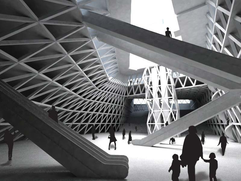
21 To create a more variating space and an experience that wasnt along corridors and ordinary spaces it was attempted to create more levels that would ínfluence the experience alot more than plain corridors. The below three drawings shows examples of this working with ramps, levels and stairs. These ideas had no clear direction or concept and seemed to be disconnected from both the stations, the existing buildings and the street level. 21

22 The atrium is the most important part of the project being the heart of the building and the most impressive view. sketching atrium The first thoughts arrived with the thought of using the Ring Building as the grand atrium and a mayor light source. The larger the atrium is the grander the experience. But this wasnt the only aspect of the project including an atrium. Early on some of the space under the S-train was decided to be a central access to the stations borrowing alitte from the existing project for the Metro Station as Nørrebro Station. This Atrium was to be nothing but access with clear connection between the S-train and Metro Station. 22

23 The Atrium it self was always meant to be one of the mayor access points. Not only was the idea to lead people through it. It was also meant to become an entrance. Much of the experience in the project was for a long time also placed here rather than the entire building. It was to be the heart. But this function seemed detached from the rest of the project that worked with corridors and much smaller spaces. 23

24 sketching underground city From the original ideas of a simple corridor the project developed into a much larger scale. A underground SPACE. Inspired by the fantasy world of Disney and such fantasy stories as Lord of the Rings came the idea of an underground city built around the pillars of the city. Even using these pillars to create space. The below illustration shows a grand space in a cave. The space s experience is very much enhanced by the presence of the large columns holding up the caves roof. The Scrooge McDuck illustrations on the other side shows how Duckburg s old houses was kept when the city was expanded and built above. The space is fascinating because it shows a space under and between the legs of the city, a space like the one above in the street. These illustrations are fascinating showing spaces that are interesting and fascinating. The wauw effect. 24
25 25
26 sketching integrated structure It was attempted to create a stronger concept by creating a structural plan on which all of the project could be developed. The first attempt was the following drawings based on a column-and-beam structure that would create a module system to create space from. This would be the under structure of the city, what keeps the city floating. The idea was to create a two storey system around corridors based on a previous plan seen on the pages before. 26

27 Although this suggestion was stronger and more logical in the approach to create space it lacked an experience other than the city underground. It was also missing a connection to the legs of the Ring Building which was at this point still three legs in the court yard. 27
28 sketching shaping Instead a focus was put on a more 3-dimensional shaping of the space. The idea was to use the shape as the carying elements of the ring buiding and the rest of the structure. The idea was to let the forces follow the shape and absorbing forces from more than direction. The idea was to use the shape as a meeting point of the pedestrians and the metro, as illustrated in the heart drawing. The thought was to create a single space that would reach out for the various fix points in the project: The Atrium, the metrostations, the s-train and the possible multistorey building on the Basar Site. This shape would be defined by the floor decks in the first thoughts. But rather than helping the creativity this limited the 3D elements of the project. Rather than trying to define the space by the decks it was easier to approach the space by shaping the space as a negative shape. 28

29 From the investigations of the 3D shape a new approach was reach where the decks was defined by the shape. But to emphasise the shape and the usefulness of the structure a column beam system of triangular shapes was added to stabilise the rings of the building. The first ideas was to create an organic shape created by the triangular structure. Because there was a requirement of having horisontal lines in the structure that would be integrated in the design the organic shapes proved to get large spans and odd angles that wouldnt suit the project. It also turned out to be hard to fit the organic shape to the existing building. A more geometric approach was used as shown below. 29

30 sketching levels From the start the issue of levels was a bit ambigious. As mention in the initial processing phase a decision was made concerning the depth of the stations. To ease the process a 4 m height was set for the floor heights, from floor slab to floor slab. The real issue was how deep the concourse level was situated and how the levels should be controlled. The first drawing shows the levels through the red lines with the boxes representing stations and the above function. The issue is how the levels will connection with street level and the stations depth. These small drawings is an example of the thoughts behind the levels. What they have in common is one strong levelled connection which was also the idea in the early stages where the entire underground structure was levelled. With development it was thought that the levels should variate to create a more interesting space. Early on the below drawings appeared with no real thought other than as a potential concept. 30
31 As the project developed into a singular shape it was decided that this shape should be part of or influenced by the levels. The below drawing shows the possible connection between the s-train and the atrium. This was to show the way the atrium would connect to the outside. The last drawing shows the basic thought for how to deal with the level difference between the two stations. As such this was one of the first suggestions that included the sloping landscape leading down to the atrium. 31

32 The levels variation was meant to develop into a underground landscape. Both for spatial experience and for functions. sketching underground landscape The development was also about creating unusable spaces that had functions. For people to sit or exhibtitions to take place. To create a sense of space. 32


33 The below drawing shows an idea for the landscape to reach above ground and become an area for people to sit in the open facing south towards the sun. The three renders on the side are quick ideas of how to deal with the levels with stairs and moving walkways integrated in the landscape. 33

34 sketching shaping The development from the organic shapes led to a more rough and geometric shape. The idea was to base the structure on the existing building and adapt it to the stations. This way the force was to be led directly down the structure. The principle and explaination follows in Principles. The below illustration is of the main atrium showing the shaped based on the forces. 34


35 The entire shape of the structure was developed into the below iterations. The red structure was the first fully developed structure done relatively fast. This is also the structure on which the Staad.PRO results is from. The structures is virtually identical. A small addition is based on the need for access to the s-train and further more adaptions was made to improve connection between the outside and inside. 35

36 sketching atrium 36
37 37
38 sketching focus areas 38
39 39
40 inspiration for the finale sketching 40
41 41
42 bo laugesen ad10-ark15 nørrebro station process
DEVELOPMENT OF THE SECTIONS
 DEVELOPMENT OF THE SECTIONS DEVELOPMENT OF SECTION A-A fig. 6.107 Early development sketch of section a-a; highlighting the need to create atrium spaces fig. 6.108 Three dimensional development of fig.
QUALITY FLOORING TRANSITIONS
 EXTRUSION, ANODISING AND POWDER COAT STANDARDS All aluminium sections are extruded to AS 1866-1997, anodized to GB 5237.2:2008 or powder coated to GB 5237.5:2008. DETERMINATION OF THE BURNING BEHAVIOUR
1. A maintenance technician sights the top of a telephone pole at a 25 angle of elevation as shown.
 Name 1. A maintenance technician sights the top of a telephone pole at a 25 angle of elevation as shown. Determine the horizontal distance between the technician and the base of the telephone pole to the
IMPORTANT -- SPECIAL INSTALLATION INSTRUCTIONS
 IMPORTANT -- SPECIAL INSTALLATION INSTRUCTIONS ** READ ALL INSTALLATION INSTRUCTIONS BEFORE STARTING!** If at any point, you have questions, call 1-800-851-0865...(The manufacturer will not be responsible
Step 2 - Measure and install joist hangers every 16". See Figure "B" above. Fill every hole in each
 Adding a deck is one of the most useful projects a homeowner can do to improve their home. Each deck is different and presents it's own set of challenges, so contact us with unique questions if they are
ASSEMBLY INSTRUCTIONS TF Tent Flooring System. 125 Taylor Parkway Archbold, Ohio Phone: (419) Fax: (419)
 Fax: (419)") 125 Taylor Parkway Archbold, Ohio 43502 Phone: (419) 445-8915 Fax: (419) 445-0367 www.biljax.com TF-2100 Tent Flooring System ASSEMBLY INSTRUCTIONS ALL DRAWINGS ARE FOR ILLUSTRATION ONLY Revision: 1 1/21/16
125 Taylor Parkway Archbold, Ohio 43502 Phone: (419) 445-8915 Fax: (419) 445-0367 www.biljax.com TF-2100 Tent Flooring System ASSEMBLY INSTRUCTIONS ALL DRAWINGS ARE FOR ILLUSTRATION ONLY Revision: 1 1/21/16
Bonus: Map Drawing Tips
 Bonus: Map Drawing Tips As a bonus to the course, we re including some tips on how to draw good maps for your future games. Some of you might feel that you are not good at drawing maps. Put another way,
Creating a Jungle Walkway
 Creating a Jungle Walkway This tutorial has been written with beginners in mind, as well as more experienced builders. Although it illustrates how to create a jungle walkway, exactly the same methods can
BuildER s Guide. Overlap technique
 full color U N O F F I C I A L THE LEGO BuildER s Guide 2 n d e d i t i o n Allan Bedford Overlap Technique Stagger technique Hybrid Column 6 Microscale Building: More Than Meets the Eye In Chapter 5,
Total precast solution for large stadium projects meet tight schedule
 Tailor Made Concrete Structures Walraven & Stoelhorst (eds) 2008 Taylor & Francis Group, London, ISBN 978-0-415-47535-8 Total precast solution for large stadium projects meet tight schedule T.J. D Arcy
Dave's Glossary of Construction Terms. by Dave Osborne (www.daveosborne.com)
") Dave's Glossary of Construction Terms by Dave Osborne (www.daveosborne.com) 5/4" A thickness of decking material between 1 x 6 and 2 x 6. Although it is called 5/4 x 6, it is actually 1" thick and 5 1/2"
Dave's Glossary of Construction Terms by Dave Osborne (www.daveosborne.com) 5/4" A thickness of decking material between 1 x 6 and 2 x 6. Although it is called 5/4 x 6, it is actually 1" thick and 5 1/2"
MARQUEE INSTALLATION HANDBOOK. Curved Structures
 MARQUEE INSTALLATION HANDBOOK Curved Structures 12m Curved Roof Beam Assembly Instructions Ensure there are no overhead or underground obstructions or services before starting to assemble frame. Square
Sunrise Deck Assembly Instructions for Kingston Left
 Sunrise Deck Assembly Instructions for Kingston Left It s easiest to build the deck frame first like it will be lying on its back and then after all 4 legs and horizontals are in place, tip the deck toward
Omarshauntedtrail.com. Obtained from. How-To build columns with propane flames. Halloween Props
 Halloween Props http://www.angelfire.com/goth/clintshalloweenprops/columns.html How-To build columns with propane flames. Parts 2x4 Boards (I used an old fence under the free section of craigslist.org)
Cylinder of Zion. Design by Bart Vossen (100932) LD1 3D Level Design, Documentation version 1.0
 LD1 3D Level Design, Documentation version 1.0") Cylinder of Zion Documentation version 1.0 Version 1.0 The document was finalized, checking and fixing minor errors. Version 0.4 The research section was added, the iterations section was finished and
Cylinder of Zion Documentation version 1.0 Version 1.0 The document was finalized, checking and fixing minor errors. Version 0.4 The research section was added, the iterations section was finished and
MODERN PERGOLA INSTALLATION GUIDE. When only the best will do.
 MODERN PERGOLA INSTALLATION GUIDE When only the best will do. TOOLS LIST Drill(s) 3/8" Magnetic Driver (s) 12" Drill Extension #2 Square Drive bit for Drill or Driver Level Tape Measure Hammer Drill if
STAGE DEX STAGE DEX. Birch plywood, special water resistant quality, anti skidding top layer
 The Stage DEX staging system consists of an aluminium frame made from a special extruded profile. The plywood top is bolted and glued to this frame to reduce noise and vibration. Several leg types and
A Canadian Canoes Information Sheet MAKING A STRONGBACK USING MANUFACTURED I-BEAMS
 A Canadian Canoes Information Sheet MAKING A STRONGBACK USING MANUFACTURED I-BEAMS BACKGROUND: We have worked with Ted Moores (author of CANOECRAFT and KAYAKCRAFT ) for 28 years. For most of that time,
Penumbra - Requiem. Game introduction and walkthrough
 Penumbra - Requiem Game introduction and walkthrough Introduction Penumbra Requiem is an expansion to Penumbra Black Plague and is to be considered an epilogue to that game and not as a new episode in
Pythagorean Theorem. If Z = 15 cm and X = 17 cm, what is the length of Y? Write your response here: (show your work)
") Pythagorean Theorem 1. To make room for the new baby, Glenn is adding a room to his house. The blueprints for the addition indicate that the room should be a rectangle with dimensions of 9 ft wide by 12
Pythagorean Theorem 1. To make room for the new baby, Glenn is adding a room to his house. The blueprints for the addition indicate that the room should be a rectangle with dimensions of 9 ft wide by 12
Example 1: The visitors are guided to the building entrance by means of increasing illumination densities.
 On the basis of three examples, luminance values are compared with each other in specific applications. The examples are the square in front of a historical function building, a train station concourse
I N T E R N A T I O N A L R E S I D E N T I A L CO D E
 I N T E R N A T I O N A L R E S I D E N T I A L CO D E 2006 STAIR BUILDING CODE Portions of this document reproduce sections from the 2006 International Residential Code, International Code Council, Falls
VILLAS LARGE SQ.FT. ( SQ.MTR.) ROLLER SHUTTER ABOVE COURTYARD VERANDAH 9 X 8-3 GARAGE 22-6 X 8-3 OUTDOOR INFINITY POOL 23 X 8-3 RAMP
 ROLLER SHUTTER ABOVE COURTYARD VERANDAH 9 X 8-3 GARAGE 22-6 X 8-3 OUTDOOR INFINITY POOL 23 X 8-3 RAMP") PLANS LARGE - 8500 SQ.FT. (789.67 SQ.MTR.) WATER FEATURE COURTYARD VERANDAH 9 X 8-3 GARAGE 22-6 X 8-3 ROLLER SHUTTER ABOVE OUTDOOR INFINITY POOL 23 X 8-3 6-6 WIDE RAMP BAR 13 X 14-3 STORE DECK 5-6 WIDE
PLANS LARGE - 8500 SQ.FT. (789.67 SQ.MTR.) WATER FEATURE COURTYARD VERANDAH 9 X 8-3 GARAGE 22-6 X 8-3 ROLLER SHUTTER ABOVE OUTDOOR INFINITY POOL 23 X 8-3 6-6 WIDE RAMP BAR 13 X 14-3 STORE DECK 5-6 WIDE
Chapter 7 - Porch Framing
 Chapter 7 - Porch Framing Contents Chapter 7 - Porch Framing... 7-1 Timing & Prerequisites... 7-2 Concrete Porches Caps (Contractor)... 7-3 Organize the Porch Framing Lumber... 7-3 Types of Porch Roofs...
Missing Sequence. You have 10 minutes to complete this test. Select the square that comes next in the sequence.
 Missing Sequence Select the square that comes next in the sequence. 1. 2. 3. Similarities 4. 5. 6. Analogies 7. 8. ` 9. Odd one out 10. 11. 12. Complete the grid 13. 14. 15. Answers 1. A- The pattern along
Instructions for measuring your pool for the EASY LADDER
 EASY LADDER Instructions for measuring your pool for the EASY LADDER Before You Begin You will need the following items: two measuring tapes a marker tape 6Easy Steps to Measuring Your for an EASY LADDER
Questions. Paul Ross Wallach V7198. Published by Hearlihy P.O. Box 1747 Pittsburg, KS
 Questions for Blueprint-Reading Exams Paul Ross Wallach Published by Hearlihy P.O. Box 1747 Pittsburg, KS 66762 866-622-1003 www.hearlihy.com 81861 V7198 Copyright 2007 by Hearlihy. Except for making transparencies
12. Pillar rebar arrangement
 12. Pillar rebar arrangement 1) Indication of pillar(c) Main bar drawing - It indicates the length of span by the criterion of pillar and wall, etc. and indicates the position of pillar & wall.
Installation Instructions for. Handrail Component System
 Handrail STEP-BY-STEP Installation Instructions for Handrail Component System Rise in Inches Run in Inches 8 8.5 9 9.5 10 10.5 11 11.5 12 12.5 13 13.5 14 14.5 15 8.5 47 45 43 42 40 39 38 36 35 34 33 32
Assembly and Installation Guide
 The Easy Hang Closet Solution SM Install Your elfa In An Instant. Enjoy The Benefits For A Lifetime. Basic Tools For elfa Assembly and Installation Level Hand or Power Drill Drill Bits 1/8", 3/8", 5/16"
SIMULATION OF CERTAIN ACOUSTIC PROPERTIES OF THE "KNEŽEV DVOR" IN DUBROVNIK
 SIMULATION OF CERTAIN ACOUSTIC PROPERTIES OF THE "KNEŽEV DVOR" IN DUBROVNIK Bojan Ivančević 1, Marjan Sikora 2, Kristian Jambrošić 1 1 FER, Unska 3, Zagreb, Croatia, bojan.ivancevic@fer.hr, kristian.jambrosic@fer.hr
VINYL CLASSIC FREESTANDING PERGOLA ASSEMBLY INSTRUCTIONS
 P a g e 1 VINYL CLASSIC FREESTANDING PERGOLA ASSEMBLY INSTRUCTIONS Shown: 8' x 12' Vinyl Classic Pergola with 12" Top and Main Runner Spacing The design of this pergola is based on all posts being installed
DEMYSTIFYING DESIGN-BUILD. How to Make the Design-Build Process Simple and Fun
 DEMYSTIFYING DESIGN-BUILD How to Make the Design-Build Process Simple and Fun What would your dream home look like? What would it feel like? What do you need, want, and wish for in the perfect house? It
7048 CDT: DESIGN AND COMMUNICATION
 www.onlineexamhelp.com www.onlineexamhelp.com UNIVERSITY OF CAMBRIDGE INTERNATIONAL EXAMINATIONS GCE Ordinary Level MARK SCHEME for the October/November 008 question paper 7048 CDT: DESIGN AND COMMUNICATION
Renders & Drafting Portfolio
 Renders & Drafting Portfolio CHADSTONE TAILOR MADE STORE (Activation) Customised store configuration example A Designer Gus Smith Producer Alex Kember SHOP VARIATIONS Renders CHADSTONE TAILOR MADE STORE
End tipping and runner wagons
 End tipping and runner wagons These wagons are based on, but not identical to, those used at the "Pike Brothers Tramway", also known as the "Furzebrook Railway". Exact replicas are difficult as photographic
Aspen Art Museum Creating Innovative Wood Structure
 Aspen Art Museum Creating Innovative Wood Structure Tallinn Wood Architecture Conference November 25-26, 2015 Aspen Art Museum Wood Space Frame THE PLAYERS OUTLINE THE BUILDING CONCEPT THE ARCHITECT S
Framing the Cabin Exterior Walls [1]
![Framing the Cabin Exterior Walls [1]](/thumbs/85/92602183.jpg "Framing the Cabin Exterior Walls [1]") [1] Submitted by Ana White [2] on Wed, 2015-05-20 16:21 [1] After a full year of prepping, Page 1 of 32 Weeks of ordering materials, planning, and hauling in those materials, the day finally arrived when
[1] Submitted by Ana White [2] on Wed, 2015-05-20 16:21 [1] After a full year of prepping, Page 1 of 32 Weeks of ordering materials, planning, and hauling in those materials, the day finally arrived when
External Timber Stairs
 Terminology Stairs: An assembly of steps or flights including all necessary landings, balustrades etc. constructed for the easy, convenient and safe passage from one floor to another. Step: A combination
technologically advanced residential design software
 technologically advanced residential design software Why SoftPlan remodel? For over thirty years, SoftPlan has delivered the most complete design solution available by listening to our customers and creating
Vinyl Gazebo Instructions
 P a g e 1 Vinyl Gazebo Instructions 10 Vinyl Gazebo Shown Thank you for the purchase of your New Gazebo. Depending on the size of your Gazebo, installation can usually be completed in 1 to 2 days. These
More on Kotatsu Tables
 More on Kotatsu Tables Adding a Kotatsu Table is one of the easiest and most effective ways to make your East-West TeaHouse even more useful, versatile and responsive. 2 x 2 Kotatsus... 3 x 2 Kotatsus...
Orthographic Drawings
 Orthographic Drawings You don t have to be an artist to draw great furniture plans. By Craig Bentzley W oodworking requires a graphic language to convey building information. We can t do it without drawings
DFTG 1305 UNIT 1. Semester: Spring 2016 Class #: Term: SS Instructor: Mays ALSabbagh
 DFTG 1305 UNIT 1 Semester: Spring 2016 Class #: 94412 Term: SS Instructor: Mays ALSabbagh Technical Drafting Unit One: Introduction to Drafting Chapter 1 : The World Wide Graphic language for Design Lecture
Personal CAD Project: Pantheon [1]
![Personal CAD Project: Pantheon [1]](/thumbs/80/82518747.jpg "Personal CAD Project: Pantheon [1]") Personal CAD Project: Pantheon [1] Clare McHugh Engineering Design 100 Section 22 22 April 2016 Having studied the ancient Roman culture and the Latin language for many years, my personal CAD project was
Personal CAD Project: Pantheon [1] Clare McHugh Engineering Design 100 Section 22 22 April 2016 Having studied the ancient Roman culture and the Latin language for many years, my personal CAD project was
Clopay Models 835/837 Sliding Door System Installation Guide
 Clopay Models 835/837 Sliding Door System Installation Guide The aim of this instruction is to guide you through the process of construction and fitting of Sliding Doors. Due to the number of sizes available
6 1/2 x 6 1/2 Flat Top Pergola
 6 / x 6 / Flat Top Pergola A S S E M B L Y G U I D E Models: Portland, Liberty O P T I O N A L A C C E S S O R Y Bolt Down Bracket Kit V.-0506 Ta b l e o f Co n t e n t s PAGE The Introduction & Overview......................................................
What is stairs? steps.
 STAIRS What is stairs? A Stair is a system of steps by which people and objects may pass from one level of a building to another. A stair is to be designed to span large vertical distance by dividing it
MATERIALS PREPARATION SETTING FENCE POSTS 01 TIP
 Skill Level: INTERMEDIATE Give these projects a try if you're a confident DIYer with a good working knowledge of a variety of tools. They can take a day or more to complete. If you can build a birdhouse
Listed below are the competencies required and examples from the aforementioned job:
 1. Technical Analysis Instructions: Describe a project for which you collected and interpreted or analyzed technical data for development of engineering designs and drawings from concepts and specifications.
Metro Series Sauna. installation instructions
 Metro Series Sauna installation instructions Please immediately check for any hidden damage that may have occurred in shipping. If any damage is found you must notify the delivering carrier within seven
H20 Beam for Elevated Slabs Application Guide
 H20 Beam for Elevated Slabs Application Guide A WORD ABOUT SAFETY High productivity depends on safety; even a minor accident causes job delays and inefficiency, which run up costs. That s why Symons, in
JUNIOR CERTIFICATE 2007 MATERIALS TECHNOLOGY (WOOD) MARKING SCHEME ORDINARY LEVEL SECTION A
 MARKING SCHEME ORDINARY LEVEL SECTION A") JUNIOR CERTIFICATE 2007 MATERIALS TECHNOLOGY (WOOD) MARKING SCHEME ORDINARY LEVEL SECTION A NOTE Please ensure that totals for each question are divided by two before entering marks on marking sheets.
JUNIOR CERTIFICATE 2007 MATERIALS TECHNOLOGY (WOOD) MARKING SCHEME ORDINARY LEVEL SECTION A NOTE Please ensure that totals for each question are divided by two before entering marks on marking sheets.
Pergola Installation Guide
 Pergola Installation Guide When only the best will do. 1 Tools Needed Installation Tools for assembly Drill(s) Miter or Circular Saw with carbide blade (cut slowly) ½" Drill Bit 5 /8" Drill Bit 5 /16"
6 1/2 x 6 1/2 Wood Grain Flat Top Pergola
 6 / x 6 / Wood Grain Flat Top Pergola A S S E M B LY G U I D E Models: Lakewood OPTIONAL ACCESSORY Bolt Down Bracket Kit Ver /AUG/0 Ta b l e o f Co n t e n t s PAGE The 6.5 x 6.5 Wo o d Grain Flat Top
Chapter 3 : D e s i g n D e v e l o p m e n t
 Chapter Chapter Chapter 3 : S.T.ART 3 : D AND e s i g DESIGN n D e DEVELOPMENT v e l o p m e n t This chapter deals with the design development of the project. It initiates the development process, illustrating
Maths Trail 5 T H & 6 T H C L A S S
 Maths Trail 5TH & 6TH CLASS A Note for Teachers and Guides Each student will need a measuring tape and a pencil. Thanks to the 6th Class pupils of Primrose Hill National School, Celbridge, 2011, who helped
Assembly Instructions for: JEAN S ULTIMATE SWING SETS
 Assembly Instructions for: JEAN S ULTIMATE SWING SETS Thank you for purchasing Forever Redwood patio furniture. Forever Redwood is built by Old-Growth Again Restoration Forestry (OGA). OGA is dedicated
Chapter 6 - Walls & Stairs
 Chapter 6 - Walls & Stairs Contents Chapter 6 - Walls & Stairs... 6-1 Timing & Prerequisites... 6-3 Wall Panel Components... 6-5 Headers... 6-7 Box Headers... 6-7 Solid Wood Headers... 6-8 Non-Load Bearing
Math Review Questions
 Math Review Questions Working with Feet and Inches A foot is broken up into twelve equal parts called inches. On a tape measure, each inch is divided into sixteenths. To add or subtract, arrange the feet
IMPORTANT -- SPECIAL INSTALLATION INSTRUCTIONS
 IMPORTANT -- SPECIAL INSTALLATION INSTRUCTIONS ** READ ALL INSTALLATION INSTRUCTIONS BEFORE STARTING!** If at any point, you have questions, call 1-800-851-0865...(The manufacturer will not be responsible
MODULAR TYPEFACE DESIGN
 MODULAR TYPEFACE DESIGN Modular Typeface A modular typeface is an alphabet constructed out of a limited number of shapes or modules that can be transformed subtly, by rotating, flipping and so on, to create
Escher s Forgotten Garden
 Escher s Forgotten Garden Cara Marcy 142 West Street, APT #2 Worcester, MA 01609 (508) 317-6694 cmarcy@wpi.edu Paul F. Messier 158 Concord Road, Apt. K27 Billerica, MA 01821 (860) 608-7870 pmessier@alum.wpi.edu
Elements of Design. Shapes
 Elements of Design Shapes Essential Question: What can shapes do to enhance a piece created in dtp? From ancient pictographs to modern logos, shapes are at the root of design. They are used to establish
10 x 10 Flat Top Two Tone Pergola
 0 x 0 Flat Top Two Tone Pergola Models: Bordeaux ASSEMBLY GUIDE OPTIONAL ACCESSORIES Arch Kit System ( Arches) Privacy Fence Panel System ( Panels & Middle Post) Bolt Down Bracket Kit ( for Pergola) Ver.0-00
10 x 10 Arch Top Pergola
 0 x 0 Arch Top Pergola I N S T A L L A T I O N G U I D E O P T I O N A L A C C E S S O R I E S Privacy Fence Panel System ( Panels & Middle Post Included) Bolt Down Bracket Kit (Set of ) Additional Shade
Dry Toilet, Version 2.0 June 17, 2015
 Dry Toilet, Version 2.0 June 17, 2015 Concrete Base When forming the concrete base, make sure it is same or slightly larger dimensions than the wooden base described below. The urine drain pipe is accommodated
Project Booklet. Structural Drafting with AutoCAD
 Project Booklet Structural Drafting with AutoCAD Introduction 1 General Setup 2 Border and Title Block 3 Drafting the Foundation Plan (Plate 1) 8 Drafting the South Elevation (Plate 2) 11 Drafting Section
Barrier posts of steel tube Ø 76 mm, Ø 89 mm, 70 x 70 mm
 of steel tube Ø 76 mm, Ø 89 mm, 70 x 70 mm Steel tube Ø 76, Ø 89, 70 x 70 mm with welded steel cap approx. 900 mm above ground, total length 1400 mm hot-dip galvanized and yellow coated with black stripes
Elements of Product design
 The real definition of. -The Elements of Design Elements of Product design Product design Lecture 4 Presentation uses material from other authors Ingredients? Like the things used to make your dinner?
Appendix D: Constructing a Seedhouse
 Appendix D: Constructing a Seedhouse 237 Appendix D: Constructing a Seedhouse! Seedhouse Features " Building the Seedhouse Frame # Seedhouse Tables $ Seedhouse Ventilators % Covering the Frame & Finishing
How to make a Wendy house Part One: The Floor and the Frame
 How to make a Wendy house Part One: The Floor and the Frame The Wendy House. This wendy house is basically a playhouse with a few feminine touches added. A wendy house can give children hours of enjoyment.
WINTER 15 EXAMINATIONS Subject Code: Model Answer- Building Drawing Page No- 01 /15
 Subject Code: 17309 Model Answer- Building Drawing Page No- 01 /15 Important Instruction to Examiners:- 1) The answers should be examined by key words & not as word to word as given in the model answers
Project: The Parklands Builder: JMac Constructions Location: Southport, Gold Coast Dates: Nov Feb 2017
 Project: The Parklands Builder: JMac Constructions Location: Southport, Gold Coast Dates: Nov 2016 - Feb 2017 Watkins Steel were contracted by JMac Constructions to supply and install structural steelwork
ASSEMBLY INSTRUCTIONS
 ASSEMBLY INSTRUCTIONS PRINTED IN USA Assembly Instructions Include: P/N: LL-04-5 Step : Site Preparation Step 0: Guard Rail Installation Step : Leg Assembly Step : Stairs Step 3-8: Setting the Stage Step
Sally s Bedroom. 12 feet. 9 Bedroom C Bedroom D feet. 11 feet. Bedroom F. 11 feet. 1. If you were choosing, which room would you choose? Why?
 Sally s Sally s family is planning to build a new house. Today they are looking at possible designs for Sally s bedroom. So far, they are thinking about the six rooms below. 9 16 12 A 6 B 10. 11 11 9 C
YOUR LIFE. YOUR FIRE. Ortal Curved & Islands Fireplaces User s Manual
 YOUR LIFE. YOUR FIRE. Ortal Curved & Islands Fireplaces User s Manual [USA Fireplace Models [THIS ISTALLATION MANUAL INCLUDES ASSEMBLY INSTRUCTIONS FOR THESE MODELS: STAND ALONE 7565 CURVED TUNNEL DOUBLE
Playground Assembly Instructions
 Before You Begin Playground Assembly Instructions Locate the playground set on firm, level ground. Assemble the playground on or close to its permanent location Two people are recommended to assemble the
Deck Tutorial. Chapter 8: Decks and Porches
 Decks and Porches Chapter 8: Deck Tutorial Now we ll continue where the Landscaping Tutorial left off and create a deck off the back of the house, connecting it to the terrain with an exterior staircase.
Weean cattle yards. Introduction. Construction materials. Features of the yard. Juliet McConochie
 JULY 2010 PRIMEFACT 263 (REPLACES AGNOTE DAI-193) Weean cattle yards Juliet McConochie Livestock Officer, Extensive Livestock Development, Walgett Introduction The real test of cattle yard design is to
*Cover Picture Hoffman House by Richard Meier. *Drawn and Rendered by. Nicole Geier
 *Cover Picture Hoffman House by Richard Meier *Drawn and Rendered by Nicole Geier Design Statement Just as soul depicts the character of man, architecture portrays the character of functional space. Architecture
SteelChief Installation Instructions for pre-assembled panel form sheds GABLE ROOF
 SteelChief Installation Instructions for pre-assembled panel form sheds GABLE ROOF Please read fully before commencing work...any queries will be promptly answered, contact theboss@steelchief.com.aui MPORTANT
Deck Tutorial. Decks and Porches. Drawing Decks
 Deck Tutorial The Deck Tutorial continues where the Landscaping Tutorial left off, and explains how to create a deck off the back of the house and connect it to the terrain with an exterior staircase.
Requirement for Holes - Holes for Hanging
 Requirement for Holes - Holes for Hanging In order for items to progress through the series of pretreatment and galvanizing baths at our facility, they must be suspended in a suitable manner to ensure
JAZZ DESIGNS. Looking for a designer that understands you and your market? B U I L D I N G D E S I G N E R S
 RESIDENTIAL DESIGN COMMERCIAL DESIGN URBAN DESIGN INTERIOR DESIGN JAZZ DESIGNS IS A PROGRESSIVE AND INNOVATIVE BUILDING DESIGN FIRM THAT IS COMMITTED TO PROVIDING ITS CLIENTS WITH A HIGH STANDARD OF BUILD
Timber projects. This section contains plans and instructions for three timber projects.
 Project Saw horse Timber projects This section contains plans and instructions for three timber projects. The projects are suggested for students to practise skills use tools from the course and make something
Typical Drawings for Schools
 0.85 1.7 0.85 3 3 0.6 3 3 0.85 1.7 0.85 0.3 4 4 1 1 2 2 0.425 0.425 0.425 0.425 1.2 2.4 1.2 0.6 0.6 4 4 1 1 3 3 0.4 0.6 0.3 0.3 3 3 4 4 0.4 4 4 1 1 2 2 Detail of (W 1.2 x 0.4 m) Detail of (W0.6 x 0.4 m)
I've Seen That Shape Before Lesson Plan
 I've Seen That Shape Before Lesson Plan I) Overview II) Conducting the Lesson III) Teacher to Teacher IV) Handouts I. OVERVIEW Lesson Summary Students learn the names and explore properties of solid geometric
Aluminum Railing Installation. Glass Railing Spindle Railings Intimacy Railings and Panels
 Aluminum Railing Installation Glass Railing Spindle Railings Intimacy Railings and Panels This information in this manual will help you to Better understand our product line. Give you guidelines for an
installation care & maintenance instructions lifecycledecking.com 25-year limited residential warranty 20-year limited commercial warranty
 installation care & maintenance instructions lifecycledecking.com 25-year limited residential warranty 20-year limited commercial warranty Installation Instructions As with any building project, use proper
8 x 8 Flat Top Pergola
 A S S E M B L Y G U I D E O P T I O N A L A C C E S S O R Y Bolt Down Bracket Kit Models: Mirage, Mandalay Ver 6/00 Ta b l e o f Co n t e n t s Introduction & Overview......................................................
6 1/2 x 6 1/2 Wood Grain Flat Top Pergola
 / x / Wood Grain Flat Top Pergola A S S E M B LY G U I D E Models: Lakewood OPTIONAL ACCESSORY Bolt Down Bracket Kit V.- Ta b l e o f Co n t e n t s The PAGE Introduction & Overview.......................................................
CONSTRUCTION / HOUSING
 CONSTRUCTION / HOUSING - PRINCE EDWARD ISLAND APPLIED MATHEMATICS 80A Table of Contents Construction/ Housing Reading a Tape Measure (Imperial)... - Using a Carpenter s Square... -5 Checking for Squareness
Deck Tutorial. Decks and Porches. Drawing Decks
 Deck Tutorial The Deck Tutorial continues where the Landscaping Tutorial left off, and explains how to create a deck off the back of the house and connect it to the terrain with an exterior staircase.
Instructions and Assembly Guide
 Corona Concepts presents The Creekside Cabin All Wood Dollhouse 1997 Corona Concepts Schenevus, NY 12155 All rights reserved These instructions were printed in New York State Instructions and Assembly
Description. Lesson Outcomes. Assumptions. Build a Floor. Carpenter
 Carpenter Description Floors are an integral part of residential construction and must be built to specifications that meet building code requirements. In this Activity Plan, students will be cutting and
10 x 10 Flat Top Pergola
 0 x 0 Flat Top Pergola A S S E M B L Y G U I D E Models: Venetian, Tuscany, Luxor, Acadia O P T I O N A L A C C E S S O R I E S Arch Kit System ( Arches) Privacy Fence Panel System ( Panels & Middle Post)
I N T E R N A T I O N A L R E S I D E N T I A L CO D E
 Visual Interpretation Of The I N T E R N A T I O N A L R E S I D E N T I A L CO D E 2004 FLORIDA RESIDENTIAL STAIR BUILDING CODE (with 2005 amendments) Portions of this document reproduce sections from
Deck Tutorial. Chapter 8: Decks and Porches
 Chapter 8: Deck Tutorial Now we ll continue where the Landscaping Tutorial left off and create a deck off the back of the house, connecting it to the terrain with an exterior staircase. You may want to