Consider two lines and. Then we could know. where. By letting L and M be orthogonal and using the fact that become
|
|
|
- Shanon Potter
- 5 years ago
- Views:
Transcription
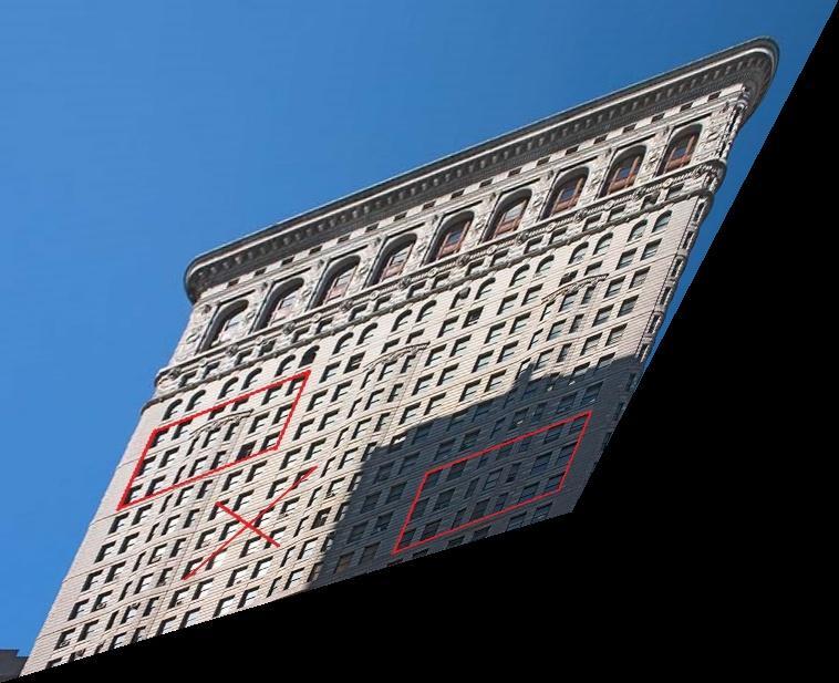
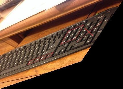
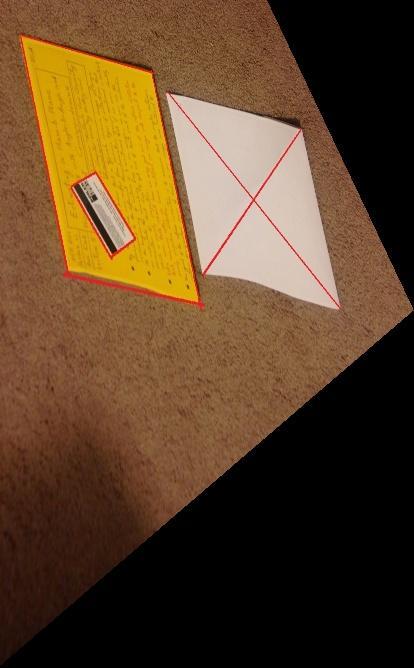
1 ECE661 Computer Vision - Fall HW3 Fu-Chen Chen chen1623@purdue.edu Remove projective distortion To remove the projective distortion we have to take back the vanishing line in the image to infinity. First we choose 2 pairs of lines they are physically parallel, then each line pair should intersect on certain point. These points are the vanishing points. Let is the vanishing line across these two vanishing points, then the homography: could make the vanishing points back to the infinite. So apply this homography would remove the projective distortion. The vanishing line of the two images of the same scene should be identical in the world space, but they are different in the image space which result in different homography. So we cannot correct the projective distortion in one image of a scene using the vanishing line from another image of the same scene Remove affine distortion Consider two lines and. Then we could know where By letting L and M be orthogonal and using the fact that become, the above formulation where is the homography that remove the affine distortion. Expanding the above formulation we get. Now we define S= =, we can got s11m1'l1' + s12(l1'm2'+l2'm1') + s22l2'm2' = 0 By the fact that we only need to know the ration of elements in homography, we could set s22=1 and apply two orthogonal line pairs to solve s11 and s12. Once we get S, since S= we could use the property of SVD that shows
2 A=, S= to obtain A and the, then we could use the homography to remove the projective and affine distortion. 2.2 Single step method A general homography that remove projective and affine distortion could be express as using the fact that, we could present the dual conic in the image plane as = If there are two lines and that are orthogonal in the world plane, we have Again we only care about the ratio of elements in conics, so we could set f=1 and solve a, b, c, d and e by 5 pairs of orthogonal lines and get. Now since we can apply SVD on S again to get A the use = to get v and build the homography H that could remove projective and affine distortion in a single step. 2.3 Compare two-step method and one-step method According to the image result, we could find that the two-step method seems to be more robust than one-step method. For example if I make a slight change of line, the result of one-step method often crash while the two-step method remain stable. Thus I conclude the one-step method is very vulnerable to noise. I think the reason is that it requires 5 pairs of orthogonal lines in world space, which means if any pair of lines are not orthogonal then the process of computing a, b, c, d, e would be problematic.


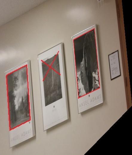
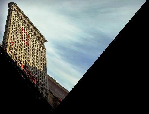
3 3. Result images (I had crop some images to reduce the image size) Set1-Img1 original projective removed


4 affine removed one-step method

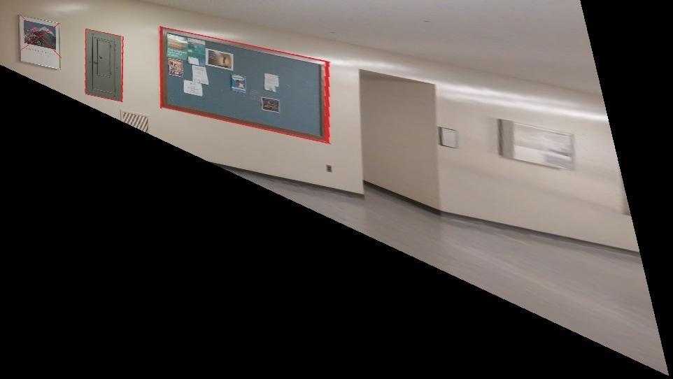
5 Set1-Img2 original projective removed


6 affine removed one-step method


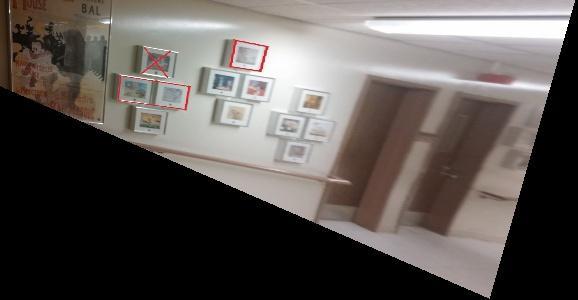
7 Set2-Img1 original projective removed

8 affine removed one-step method

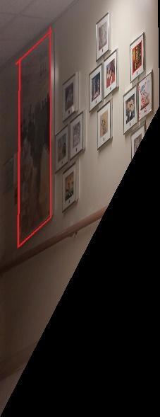
9 Set2-Img2 original projective removed


10 affine removed one-step method

11 Set3-Img1 original projective removed

12 affine removed one-step method

13 Set3-Img2 original projective removed

14 affine removed one-step method

15 Set4-Img1 original projective removed

16 affine removed one-step method

17 Set4-Img2 original projective removed

18 affine removed one-step method

19 My Image 000 original projective removed


20 affine removed one-step method

21 My Image 001 original projective removed

22 affine removed one-step method

23 My Image 002 original projective removed

24 affine removed one-step method
technical drawing school of art, design and architecture sarah adeel nust spring 2011
 technical drawing school of art, design and architecture sarah adeel nust spring 2011 the ability to document imagination. a mean to design reasoning spring 2011 perspective drawings technical drawing
PROJECTIONS PARALLEL CONICAL PROJECTIONS PROJECTIONS OBLIQUE ORTHOGRAPHIC PROJECTIONS PROJECTIONS
 PROJECTIONS CONICAL PROJECTIONS PARALLEL PROJECTIONS OBLIQUE PROJECTIONS ORTHOGRAPHIC PROJECTIONS ISOMETRIC MULTI-VIEW an object; The Description of Forms Behind every drawing of an object is space relationship
Lecture 7: homogeneous coordinates
 Lecture 7: homogeneous Dr. Richard E. Turner (ret26@cam.ac.uk) October 31, 2013 House keeping webpage: http://cbl.eng.cam.ac.uk/public/turner/teaching Recap of last lecture: Pin hole camera image plane
Perspective in Art. Yuchen Wu 07/20/17. Mathematics in the universe. Professor Hubert Bray. Duke University
 Perspective in Art Yuchen Wu 07/20/17 Mathematics in the universe Professor Hubert Bray Duke University Introduction: Although it is believed that science is almost everywhere in our daily lives, few people
Chapter 5. Drawing a cube. 5.1 One and two-point perspective. Math 4520, Spring 2015
 Chapter 5 Drawing a cube Math 4520, Spring 2015 5.1 One and two-point perspective In Chapter 5 we saw how to calculate the center of vision and the viewing distance for a square in one or two-point perspective.
Transform 3D objects on to a 2D plane using projections
 PROJECTIONS 1 Transform 3D objects on to a 2D plane using projections 2 types of projections Perspective Parallel In parallel projection, coordinate positions are transformed to the view plane along parallel
Projections. Conceptual Model of the 3D viewing process
 Projections Projections Conceptual Model of the 3D viewing process 3D Projections (Rays converge on eye position) (Rays parallel to view plane) Perspective Parallel Orthographic Oblique Elevations Axonometric
3D Viewing. Introduction to Computer Graphics Torsten Möller / Manfred Klaffenböck. Machiraju/Zhang/Möller
 3D Viewing Introduction to Computer Graphics Torsten Möller / Manfred Klaffenböck Machiraju/Zhang/Möller Reading Chapter 5 of Angel Chapter 13 of Hughes, van Dam, Chapter 7 of Shirley+Marschner Machiraju/Zhang/Möller
Exposing Photo Manipulation with Geometric Inconsistencies
 Exposing Photo Manipulation with Geometric Inconsistencies James F. O Brien U.C. Berkeley Collaborators Hany Farid Eric Kee Valentina Conotter Stephen Bailey 1 image-forensics-pg14.key - October 9, 2014
.VP CREATING AN INVENTED ONE POINT PERSPECTIVE SPACE
 PAGE ONE Organize an invented 1 point perspective drawing in the following order: 1 Establish an eye level 2 Establish a Center Line Vision eye level vision Remember that the vanishing point () in one
Introduction to Projection The art of representing a three-dimensional object or scene in a 2D space is called projection.
 Introduction to Projection The art of representing a three-dimensional object or scene in a 2D space is called projection. Projection is carried out by passing projectors through each vertex and intersecting
Projection. Announcements. Müller-Lyer Illusion. Image formation. Readings Nalwa 2.1
 Announcements Mailing list (you should have received messages) Project 1 additional test sequences online Projection Readings Nalwa 2.1 Müller-Lyer Illusion Image formation object film by Pravin Bhat http://www.michaelbach.de/ot/sze_muelue/index.html
Image stitching. Image stitching. Video summarization. Applications of image stitching. Stitching = alignment + blending. geometrical registration
 Image stitching Stitching = alignment + blending Image stitching geometrical registration photometric registration Digital Visual Effects, Spring 2006 Yung-Yu Chuang 2005/3/22 with slides by Richard Szeliski,
Two strategies for realistic rendering capture real world data synthesize from bottom up
 Recap from Wednesday Two strategies for realistic rendering capture real world data synthesize from bottom up Both have existed for 500 years. Both are successful. Attempts to take the best of both world
Short Introduction to Planes Not on EL VPs (Pitches and Inclined Planes)
") Short Introduction to Planes Not on VPs (Pitches and Inclined Planes) Planes Not on VPs (Pitches and Inclined Planes) Print this page to use as your source drawing guide Short Introduction to Planes Not
Short Introduction to Planes Not on VPs (Pitches and Inclined Planes) Planes Not on VPs (Pitches and Inclined Planes) Print this page to use as your source drawing guide Short Introduction to Planes Not
Projection. Readings. Szeliski 2.1. Wednesday, October 23, 13
 Projection Readings Szeliski 2.1 Projection Readings Szeliski 2.1 Müller-Lyer Illusion by Pravin Bhat Müller-Lyer Illusion by Pravin Bhat http://www.michaelbach.de/ot/sze_muelue/index.html Müller-Lyer
Using Line and Ellipse Features for Rectification of Broadcast Hockey Video
 Using Line and Ellipse Features for Rectification of Broadcast Hockey Video Ankur Gupta, James J. Little, Robert J. Woodham Laboratory for Computational Intelligence (LCI) The University of British Columbia
Cameras. CSE 455, Winter 2010 January 25, 2010
 Cameras CSE 455, Winter 2010 January 25, 2010 Announcements New Lecturer! Neel Joshi, Ph.D. Post-Doctoral Researcher Microsoft Research neel@cs Project 1b (seam carving) was due on Friday the 22 nd Project
IEEE TRANSACTIONS ON IMAGE PROCESSING VOL. XX, NO. X, MONTH YEAR 1. Affine Covariant Features for Fisheye Distortion Local Modelling
 IEEE TRANSACTIONS ON IMAGE PROCESSING VOL. XX, NO. X, MONTH YEAR Affine Covariant Features for Fisheye Distortion Local Modelling Antonino Furnari, Giovanni Maria Farinella, Member, IEEE, Arcangelo Ranieri
HS PUMP. Spring 2010 CSUN Math. Perspective
 1. During the 15th century, artists and architects developed a new technique, linear perspective, for painting real world scenes on a canvas. The idea and practice of perspective drawing or linear perspective
MIT CSAIL Advances in Computer Vision Fall Problem Set 6: Anaglyph Camera Obscura
 MIT CSAIL 6.869 Advances in Computer Vision Fall 2013 Problem Set 6: Anaglyph Camera Obscura Posted: Tuesday, October 8, 2013 Due: Thursday, October 17, 2013 You should submit a hard copy of your work
Projection. Projection. Image formation. Müller-Lyer Illusion. Readings. Readings. Let s design a camera. Szeliski 2.1. Szeliski 2.
 Projection Projection Readings Szeliski 2.1 Readings Szeliski 2.1 Müller-Lyer Illusion Image formation object film by Pravin Bhat http://www.michaelbach.de/ot/sze_muelue/index.html Let s design a camera
VIEWING 1. CLASSICAL AND COMPUTER VIEWING. Computer Graphics
 VIEWING We now investigate the multitude of ways in which we can describe our virtual camera. Along the way, we examine related topics, such as the relationship between classical viewing techniques and
Analog Circuits Prof. Jayanta Mukherjee Department of Electrical Engineering Indian Institute of Technology-Bombay
 Analog Circuits Prof. Jayanta Mukherjee Department of Electrical Engineering Indian Institute of Technology-Bombay Week -02 Module -01 Non Idealities in Op-Amp (Finite Gain, Finite Bandwidth and Slew Rate)
Structured-Light Based Acquisition (Part 1)
") Structured-Light Based Acquisition (Part 1) CS635 Spring 2017 Daniel G. Aliaga Department of Computer Science Purdue University Passive vs. Active Acquisition Passive + Just take pictures + Does not intrude
Structured-Light Based Acquisition (Part 1) CS635 Spring 2017 Daniel G. Aliaga Department of Computer Science Purdue University Passive vs. Active Acquisition Passive + Just take pictures + Does not intrude
Graphics and Interaction Perspective Geometry
 433-324 Graphics and Interaction Perspective Geometr Department of Computer Science and Software Engineering The Lecture outline Introduction to perspective geometr Perspective Geometr Centre of projection
Video 8: 2 Point Perspective
 Video 8: 2 Point Perspective Two point perspective is a drawing method using lines to create the illusion of space on a 2-Dimensional surface. Two point perspective is one of the six ways an artist can
The Camera : Computational Photography Alexei Efros, CMU, Fall 2008
 The Camera 15-463: Computational Photography Alexei Efros, CMU, Fall 2008 How do we see the world? object film Let s design a camera Idea 1: put a piece of film in front of an object Do we get a reasonable
IMAGE FORMATION. Light source properties. Sensor characteristics Surface. Surface reflectance properties. Optics
 IMAGE FORMATION Light source properties Sensor characteristics Surface Exposure shape Optics Surface reflectance properties ANALOG IMAGES An image can be understood as a 2D light intensity function f(x,y)
CSE 473/573 Computer Vision and Image Processing (CVIP)
") CSE 473/573 Computer Vision and Image Processing (CVIP) Ifeoma Nwogu inwogu@buffalo.edu Lecture 4 Image formation(part I) Schedule Last class linear algebra overview Today Image formation and camera properties
CSE 473/573 Computer Vision and Image Processing (CVIP) Ifeoma Nwogu inwogu@buffalo.edu Lecture 4 Image formation(part I) Schedule Last class linear algebra overview Today Image formation and camera properties
Princeton University COS429 Computer Vision Problem Set 1: Building a Camera
 Princeton University COS429 Computer Vision Problem Set 1: Building a Camera What to submit: You need to submit two files: one PDF file for the report that contains your name, Princeton NetID, all the
COPYRIGHTED MATERIAL. Overview
 In normal experience, our eyes are constantly in motion, roving over and around objects and through ever-changing environments. Through this constant scanning, we build up experience data, which is manipulated
ONE POINT PERSPECTIVE
 ONE POINT PERSPECTIVE O che dolce cosa è questa prospettiva! (Oh that sweet thing is this perspective!) -Paolo Uccello Linear Perspective Line-based drawing method Objects seem to get smaller as they recede.
COPYRIGHTED MATERIAL OVERVIEW 1
 OVERVIEW 1 In normal experience, our eyes are constantly in motion, roving over and around objects and through ever-changing environments. Through this constant scanning, we build up experiential data,
Develop an Interior perspective from a floor plan using 2 points. using orthographic projection techniques
 Develop an Interior perspective from a floor plan using 2 points using orthographic projection techniques Obtain a floor of the space to be drawn Digital or hand drawn plan Plan must be to scale Often
Unit 5: Unified Software Development Process. 3C05: Unified Software Development Process USDP. USDP for your project. Iteration Workflows.
 Unit 5: Unified Software Development Process 3C05: Unified Software Development Process Objectives: Introduce the main concepts of iterative and incremental development Discuss the main USDP phases 1 2
Homographies and Mosaics
 Homographies and Mosaics Jeffrey Martin (jeffrey-martin.com) with a lot of slides stolen from Steve Seitz and Rick Szeliski 15-463: Computational Photography Alexei Efros, CMU, Fall 2011 Why Mosaic? Are
ECE 255, MOSFET Amplifiers
 ECE 255, MOSFET Amplifiers 26 October 2017 In this lecture, the basic configurations of MOSFET amplifiers will be studied similar to that of BJT. Previously, it has been shown that with the transistor
Colour correction for panoramic imaging
 Colour correction for panoramic imaging Gui Yun Tian Duke Gledhill Dave Taylor The University of Huddersfield David Clarke Rotography Ltd Abstract: This paper reports the problem of colour distortion in
Homographies and Mosaics
 Homographies and Mosaics Jeffrey Martin (jeffrey-martin.com) CS194: Image Manipulation & Computational Photography with a lot of slides stolen from Alexei Efros, UC Berkeley, Fall 2014 Steve Seitz and
CHAPTER 1 INTRODUCTION
 CHAPTER 1 INTRODUCTION 1.1 Historical Background Recent advances in Very Large Scale Integration (VLSI) technologies have made possible the realization of complete systems on a single chip. Since complete
Geometric Quality Assessment of CBERS-2. Julio d Alge Ricardo Cartaxo Guaraci Erthal
 Geometric Quality Assessment of CBERS-2 Julio d Alge Ricardo Cartaxo Guaraci Erthal Contents Monitoring CBERS-2 scene centers Satellite orbit control Band-to-band registration accuracy Detection and control
Sequential Algorithm for Robust Radiometric Calibration and Vignetting Correction
 Sequential Algorithm for Robust Radiometric Calibration and Vignetting Correction Seon Joo Kim and Marc Pollefeys Department of Computer Science University of North Carolina Chapel Hill, NC 27599 {sjkim,
Systems of Orthogonal Circles and Poincarè Geometry, on the TI-92
 Proceedings of the Third DERIVE/TI-92 Conference Systems of Orthogonal Circles and Poincarè Geometry, on the TI-92 Paul Beem Indiana University South Bend, IN pbeem@iusb.edu When we encounter hyperbolic
Lecture 8 Camera Models
 Lecture 8 Caera Models Professor Silvio Savarese Coputational Vision and Geoetr Lab Silvio Savarese Lecture 8-5-Oct-4 Lecture 8 Caera Models Pinhole caeras Caeras & lenses The geoetr of pinhole caeras
2. Introduction to MOS Amplifiers: Transfer Function Biasing & Small-Signal-Model Concepts
 2. Introduction to MOS Amplifiers: Transfer Function Biasing & Small-Signal-Model Concepts Reading: Sedra & Smith Sec. 5.4 (S&S 5 th Ed: Sec. 4.4) ECE 102, Fall 2011, F. Najmabadi NMOS Transfer Function
Dual-fisheye Lens Stitching for 360-degree Imaging & Video. Tuan Ho, PhD. Student Electrical Engineering Dept., UT Arlington
 Dual-fisheye Lens Stitching for 360-degree Imaging & Video Tuan Ho, PhD. Student Electrical Engineering Dept., UT Arlington Introduction 360-degree imaging: the process of taking multiple photographs and
Mosaicing of Camera-captured. Document Images
 Mosaicing of Camera-captured Document Images 1 Jian Liang a, Daniel DeMenthon b, David Doermann b 2 3 4 a Jian Liang is with Amazon.com; Seattle, WA; USA. b Daniel DeMenthon and David Doermann are with
constant EXAMPLE #4:
 Linear Equations in One Variable (1.1) Adding in an equation (Objective #1) An equation is a statement involving an equal sign or an expression that is equal to another expression. Add a constant value
Introduction to Computer Graphics (CS602) Lecture 19 Projections
 Lecture 19 Projections") Introduction to Computer Graphics (CS602) Lecture 19 Projections For centuries, artists, engineers, designers, drafters, and architects have been facing difficulties and constraints imposed by the problem
Introduction to Computer Graphics (CS602) Lecture 19 Projections For centuries, artists, engineers, designers, drafters, and architects have been facing difficulties and constraints imposed by the problem
Overview. Pinhole camera model Projective geometry Vanishing points and lines Projection matrix Cameras with Lenses Color Digital image
 Camera & Color Overview Pinhole camera model Projective geometry Vanishing points and lines Projection matrix Cameras with Lenses Color Digital image Book: Hartley 6.1, Szeliski 2.1.5, 2.2, 2.3 The trip
Laboratory Assignment: EM Numerical Modeling of a Monopole
 Laboratory Assignment: EM Numerical Modeling of a Monopole Names: Objective This laboratory experiment provides a hands-on tutorial for drafting an antenna (simple monopole) and simulating radiation in
Image formation - Cameras. Grading & Project. About the course. Tentative Schedule. Course Content. Students introduction
 About the course Instructors: Haibin Ling (hbling@temple, Wachman 35) Hours Lecture: Tuesda 5:3-8:pm, TTLMAN 43B Office hour: Tuesda 3: - 5:pm, or b appointment Textbook Computer Vision: Models, Learning,
PHY 1160C Homework Chapter 26: Optical Instruments Ch 26: 2, 3, 5, 9, 13, 15, 20, 25, 27
 PHY 60C Homework Chapter 26: Optical Instruments Ch 26: 2, 3, 5, 9, 3, 5, 20, 25, 27 26.2 A pin-hole camera is used to take a photograph of a student who is.8 m tall. The student stands 2.7 m in front
6.A44 Computational Photography
 Add date: Friday 6.A44 Computational Photography Depth of Field Frédo Durand We allow for some tolerance What happens when we close the aperture by two stop? Aperture diameter is divided by two is doubled
HW#02 (18 pts): All recommended exercises from JIT (1 pt/problem)
: All recommended exercises from JIT (1 pt/problem)") Spring 2011 MthSc103 Course Calendar Page 1 of 7 January W 12 Syllabus/Course Policies BST Review Th 13 Basic Skills Test F 14 JIT 1.1 1.3: Numbers, Fractions, Parentheses JIT 1.1: 2, 6, 8, 9 JIT 1.2:
Spring 2011 MthSc103 Course Calendar Page 1 of 7 January W 12 Syllabus/Course Policies BST Review Th 13 Basic Skills Test F 14 JIT 1.1 1.3: Numbers, Fractions, Parentheses JIT 1.1: 2, 6, 8, 9 JIT 1.2:
4) Click on Load Point Cloud to load the.czp file from Scene. Open Intersection_Demo.czp
 Click on Load Point Cloud to load the.czp file from Scene. Open Intersection_Demo.czp") Intersection 2D Demo 1) Open the Crash Zone or Crime Zone diagram program. 2) Click on to open the CZ Point Cloud tool. 3) Click on 3D/Cloud Preferences. a) Set the Cloud File Units (Feet or Meters). b)
Intersection 2D Demo 1) Open the Crash Zone or Crime Zone diagram program. 2) Click on to open the CZ Point Cloud tool. 3) Click on 3D/Cloud Preferences. a) Set the Cloud File Units (Feet or Meters). b)
Reading. Angel. Chapter 5. Optional
 Projections Reading Angel. Chapter 5 Optional David F. Rogers and J. Alan Adams, Mathematical Elements for Computer Graphics, Second edition, McGraw-Hill, New York, 1990, Chapter 3. The 3D synthetic camera
Image Processing & Projective geometry
 Image Processing & Projective geometry Arunkumar Byravan Partial slides borrowed from Jianbo Shi & Steve Seitz Color spaces RGB Red, Green, Blue HSV Hue, Saturation, Value Why HSV? HSV separates luma,
Understanding Focal Length
 JANUARY 19, 2018 BEGINNER Understanding Focal Length Featuring DIANE BERKENFELD, DAVE BLACK, MIKE CORRADO & LINDSAY SILVERMAN Focal length, usually represented in millimeters (mm), is the basic description
SMARTSCAN Smart Pushbroom Imaging System for Shaky Space Platforms
 SMARTSCAN Smart Pushbroom Imaging System for Shaky Space Platforms Klaus Janschek, Valerij Tchernykh, Sergeij Dyblenko SMARTSCAN 1 SMARTSCAN Smart Pushbroom Imaging System for Shaky Space Platforms Klaus
In addition to one-point perespective, another common perspective
 CHAPTR 5 Two-Point Perspective In addition to one-point perespective, another common perspective drawing technique is two-point perspective, illustrated in Figure 5.1. Unless otherwise stated, we will
Dr. Reham Karam. Perspective Drawing. For Artists & Designers. By : Dr.Reham Karam
 Perspective Drawing For Artists & Designers By : Dr.Reham Karam Geometry and Art : What is perspective? Perspective, in the vision and visual perception, is : the way that objects appear to the eye based
Non-linear Control. Part III. Chapter 8
 Chapter 8 237 Part III Chapter 8 Non-linear Control The control methods investigated so far have all been based on linear feedback control. Recently, non-linear control techniques related to One Cycle
ON THE CREATION OF PANORAMIC IMAGES FROM IMAGE SEQUENCES
 ON THE CREATION OF PANORAMIC IMAGES FROM IMAGE SEQUENCES Petteri PÖNTINEN Helsinki University of Technology, Institute of Photogrammetry and Remote Sensing, Finland petteri.pontinen@hut.fi KEY WORDS: Cocentricity,
A variable step-size LMS adaptive filtering algorithm for speech denoising in VoIP
 7 3rd International Conference on Computational Systems and Communications (ICCSC 7) A variable step-size LMS adaptive filtering algorithm for speech denoising in VoIP Hongyu Chen College of Information
Computational Rephotography
 Computational Rephotography SOONMIN BAE MIT Computer Science and Artificial Intelligence Laboratory ASEEM AGARWALA Abobe Systems, Inc. and FRÉDO DURAND MIT Computer Science and Artificial Intelligence
FourPortsWidebandPatternDiversityMIMOAntenna
 Global Journal of Researches in Engineering: F Electrical and Electronics Engineering Volume 15 Issue 3 Version 1. Type: Double Blind Peer Reviewed International Research Journal Publisher: Global Journals
multiframe visual-inertial blur estimation and removal for unmodified smartphones
 multiframe visual-inertial blur estimation and removal for unmodified smartphones, Severin Münger, Carlo Beltrame, Luc Humair WSCG 2015, Plzen, Czech Republic images taken by non-professional photographers
Computational Re-Photography Soonmin Bae, Aseem Agarwala, and Fredo Durand
 Computer Science and Artificial Intelligence Laboratory Technical Report MIT-CSAIL-TR-2010-016 CBCL-287 April 7, 2010 Computational Re-Photography Soonmin Bae, Aseem Agarwala, and Fredo Durand massachusetts
SHADOW PHOTOGRAPHY. By Nelleke Ferreira
 SHADOW PHOTOGRAPHY By Nelleke Ferreira Intro Making shadows the object of our photography. A theme a bit more abstract. Lets be creative! Release the Peter Pan within, and capture some photos OF shadows.
10 GRAPHING LINEAR EQUATIONS
 0 GRAPHING LINEAR EQUATIONS We now expand our discussion of the single-variable equation to the linear equation in two variables, x and y. Some examples of linear equations are x+ y = 0, y = 3 x, x= 4,
Antennas and Propagation. Chapter 4: Antenna Types
 Antennas and Propagation : Antenna Types 4.4 Aperture Antennas High microwave frequencies Thin wires and dielectrics cause loss Coaxial lines: may have 10dB per meter Waveguides often used instead Aperture
LENSES. INEL 6088 Computer Vision
 LENSES INEL 6088 Computer Vision Digital camera A digital camera replaces film with a sensor array Each cell in the array is a Charge Coupled Device light-sensitive diode that converts photons to electrons
Interactive Computer Graphics A TOP-DOWN APPROACH WITH SHADER-BASED OPENGL
 International Edition Interactive Computer Graphics A TOP-DOWN APPROACH WITH SHADER-BASED OPENGL Sixth Edition Edward Angel Dave Shreiner 228 Chapter 4 Viewing Front elevation Elevation oblique Plan oblique
The Relativity of Conics and Circles
 Forum Geometricorum Volume 18 (2018) 1 6. FORUM GEOM ISSN 1534-1178 The Relativity of Conics and Circles Stefan Liebscher and Dierck-E. Liebscher Abstract. Foci are defined for a pair of conics. They are
UNIT 5a STANDARD ORTHOGRAPHIC VIEW DRAWINGS
 UNIT 5a STANDARD ORTHOGRAPHIC VIEW DRAWINGS 5.1 Introduction Orthographic views are 2D images of a 3D object obtained by viewing it from different orthogonal directions. Six principal views are possible
Laboratory 9. Required Components: Objectives. Optional Components: Operational Amplifier Circuits (modified from lab text by Alciatore)
") Laboratory 9 Operational Amplifier Circuits (modified from lab text by Alciatore) Required Components: 1x 741 op-amp 2x 1k resistors 4x 10k resistors 1x l00k resistor 1x 0.1F capacitor Optional Components:
Laboratory 9 Operational Amplifier Circuits (modified from lab text by Alciatore) Required Components: 1x 741 op-amp 2x 1k resistors 4x 10k resistors 1x l00k resistor 1x 0.1F capacitor Optional Components:
Panoramas. CS 178, Spring Marc Levoy Computer Science Department Stanford University
 Panoramas CS 178, Spring 2010 Marc Levoy Computer Science Department Stanford University What is a panorama?! a wider-angle image than a normal camera can capture! any image stitched from overlapping photographs!
Reconstructing Virtual Rooms from Panoramic Images
 Reconstructing Virtual Rooms from Panoramic Images Dirk Farin, Peter H. N. de With Contact address: Dirk Farin Eindhoven University of Technology (TU/e) Embedded Systems Institute 5600 MB, Eindhoven, The
Table of Contents. List of Figures. List of Abbreviations
 LAMP-TR-151 November 2008 COMPUTER VISION AND IMAGE PROCESSING LARGE TECHNIQUES FOR MOBILE APPLICATIONS Xu Liu, David Doermann Language and Media Processing Laboratory Institute for Advanced Computer Studies
Math 3560 HW Set 6. Kara. October 17, 2013
 Math 3560 HW Set 6 Kara October 17, 013 (91) Let I be the identity matrix 1 Diagonal matrices with nonzero entries on diagonal form a group I is in the set and a 1 0 0 b 1 0 0 a 1 b 1 0 0 0 a 0 0 b 0 0
REVIEW SHEET FOR MIDTERM 2: ADVANCED
 REVIEW SHEET FOR MIDTERM : ADVANCED MATH 195, SECTION 59 (VIPUL NAIK) To maximize efficiency, please bring a copy (print or readable electronic) of this review sheet to the review session. The document
Lecture # 7 Coordinate systems and georeferencing
 Lecture # 7 Coordinate systems and georeferencing Coordinate Systems Coordinate reference on a plane Coordinate reference on a sphere Coordinate reference on a plane Coordinates are a convenient way of
ONE-POINT PERSPECTIVE
 NAME: PERIOD: PERSPECTIVE Linear Perspective Linear Perspective is a technique for representing 3-dimensional space on a 2- dimensional (paper) surface. This method was invented during the Renaissance
Detection and Tracking of the Vanishing Point on a Horizon for Automotive Applications
 Detection and Tracking of the Vanishing Point on a Horizon for Automotive Applications Young-Woo Seo and Ragunathan (Raj) Rajkumar GM-CMU Autonomous Driving Collaborative Research Lab Carnegie Mellon University
USING LENSES A Guide to Getting the Most From Your Glass
 USING LENSES A Guide to Getting the Most From Your Glass DAN BAILEY A Guide to Using Lenses Lenses are your camera s eyes to the world and they determine the overall look of your imagery more than any
Exploring 3D in Flash
 1 Exploring 3D in Flash We live in a three-dimensional world. Objects and spaces have width, height, and depth. Various specialized immersive technologies such as special helmets, gloves, and 3D monitors
TESTING VISUAL TELESCOPIC DEVICES
 TESTING VISUAL TELESCOPIC DEVICES About Wells Research Joined TRIOPTICS mid 2012. Currently 8 employees Product line compliments TRIOPTICS, with little overlap Entry level products, generally less expensive
How do we see the world?
 The Camera 1 How do we see the world? Let s design a camera Idea 1: put a piece of film in front of an object Do we get a reasonable image? Credit: Steve Seitz 2 Pinhole camera Idea 2: Add a barrier to
MADE EASY a step-by-step guide
 Perspective MADE EASY a step-by-step guide Coming soon! June 2015 ROBBIE LEE One-Point Perspective Let s start with one of the simplest, yet most useful approaches to perspective drawing: one-point perspective.
Computer Vision. The Pinhole Camera Model
 Computer Vision The Pinhole Camera Model Filippo Bergamasco (filippo.bergamasco@unive.it) http://www.dais.unive.it/~bergamasco DAIS, Ca Foscari University of Venice Academic year 2017/2018 Imaging device
Cropping And Sizing Information
 and General The procedures and techniques described herein are intended to provide a means of modifying digital images for use in projection situations. This includes images being displayed on a screen
Astronomy 80 B: Light. Lecture 9: curved mirrors, lenses, aberrations 29 April 2003 Jerry Nelson
 Astronomy 80 B: Light Lecture 9: curved mirrors, lenses, aberrations 29 April 2003 Jerry Nelson Sensitive Countries LLNL field trip 2003 April 29 80B-Light 2 Topics for Today Optical illusion Reflections
MATH 255 Applied Honors Calculus III Winter Homework 1. Table 1: 11.1:8 t x y
 MATH 255 Applied Honors Calculus III Winter 2 Homework Section., pg. 692: 8, 24, 43. Section.2, pg. 72:, 2 (no graph required), 32, 4. Section.3, pg. 73: 4, 2, 54, 8. Section.4, pg. 79: 6, 35, 46. Solutions.:
1. What are the coordinates for the viewer s eye?
 Part I In this portion of the assignment, you are going to draw the same cube in different positions, using the Perspective Theorem. You will then use these pictures to make observations that should reinforce
Designing Information Devices and Systems I Fall 2015 Anant Sahai, Ali Niknejad Homework 9. This homework is due November 2, 2015, at Noon.
 EECS 16A Designing Information Devices and Systems I Fall 2015 Anant Sahai, Ali Niknejad Homework 9 This homework is due November 2, 2015, at Noon. 1. Homework process and study group Who else did you
Mathematics Algebra II Unit 11: Conic Sections
 Mathematics Algebra II Unit 11: Conic Sections 2013 201 1 What conic section is formed when a plane is passed through a cone parallel to its base? 5 raph the following: (x 3) 2 (y + 2) 2 = 36 2 Complete
2 Point Perspective. Point Perspective. Slide 1 of 40: Requirements
 2 Slide 1 of 40: Requirements Before we move on to How to draw a two point perspective, you will require a plan and an elevation of the Object you wish to draw perspective of. With a more complex object
Laboratory 2: PV Module Current-Voltage Measurements
 Laboratory 2: PV Module Current-Voltage Measurements Introduction and Background The current-voltage (I-V) characteristic is the basic descriptor of photovoltaic device performance. A fundamental understanding