3D Viewing. Introduction to Computer Graphics Torsten Möller / Manfred Klaffenböck. Machiraju/Zhang/Möller
|
|
|
- Alexander Wright
- 5 years ago
- Views:
Transcription
1 3D Viewing Introduction to Computer Graphics Torsten Möller / Manfred Klaffenböck Machiraju/Zhang/Möller
2 Reading Chapter 5 of Angel Chapter 13 of Hughes, van Dam, Chapter 7 of Shirley+Marschner Machiraju/Zhang/Möller 2
3 Objectives What kind of camera we use? (pinhole) What projections make sense Orthographic Perspective The viewing pipeline Viewing in WebGL Shadows Machiraju/Zhang/Möller 3
4 3D Viewing Popular analogy: virtual camera taking pictures in a virtual world The process of getting an image onto the computer screen is like that of taking a snapshot. Machiraju/Zhang/Möller 4
5 3D Viewing (2) With a camera, one: establishes the view opens the shutter and exposes the film Machiraju/Zhang/Möller 5
6 3D Viewing (3) With a camera, one: establishes the view opens the shutter and exposes the film With a computer, one: chooses a projection type (not necessarily perspective) establishes the view clips the scene according to the view projects the scene onto the computer display Machiraju/Zhang/Möller 6


7 Normal Camera Lens Machiraju/Zhang/Möller 7

8 Machiraju/Zhang/Möller 8

9 The ideal pinhole camera Single ray of light gets through small pinhole Film placed on side of box opposite to pinhole Projection Machiraju/Zhang/Möller 9
10 The pinhole camera Angle of view (always fixed) Depth of field (DOF): infinite every point within the field of view is in focus (the image of a point is a point) Problem: just a single ray of light & fixed view angle Solution: pinhole lens, DOF no longer infinite Machiraju/Zhang/Möller 10
11 The synthetic camera model Image formed in front of the camera Center of projection (COP): center of the lens (eye) Machiraju/Zhang/Möller 11
12 Types of projections Choose an appropriate type of projection (not necessarily perspective) Establishes the view: direction and orientation Machiraju/Zhang/Möller 12
13 3D viewing with a computer Clips scene with respect to a view volume Usually finite to avoid extraneous objects Projects the scene onto a projection plane In a similar way as for the synthetic camera model Everything in view volume is in focus Depth-of-field (blurring) effects may be generated Machiraju/Zhang/Möller 13
14 Where are we at? Clip against 3D view volume Project onto projection plane Machiraju/Zhang/Möller 14
15 Objectives What kind of camera we use? (pinhole) What projections make sense Orthographic Perspective The viewing pipeline Viewing in WebGL Shadows Machiraju/Zhang/Möller 15
16 Projection: 3D 2D We study planar geometric projections: projecting onto a flat 2D surface project using straight lines Projection rays, called projectors, are sent through each point in the scene from the centre of projection (COP) - our pinhole Intersection between projectors and projection plane form the projection Machiraju/Zhang/Möller 16
17 Perspective and parallel projections Perspective: - Determined by COP Parallel: COP at infinity By direction of projectors (DOP) Machiraju/Zhang/Möller 17
18 COP in homogeneous coordinates Perspective projection: COP is a finite point: (x, y, z, 1) Parallel projection Direction of projection is a vector: (x, y, z, 1) (x, y, z, 1) = (a, b, c, 0) Points at infinity and directions correspond in a natural way Machiraju/Zhang/Möller 18
19 Perspective vs. parallel Perspective projection: Realistic, mimicking our human visual system Foreshortening: size of perspective projection of object varies inversely with the distance of that object from the center of projection Distances, angles, parallel lines are not preserved Parallel projection: Less realistic but can be used for measurements Foreshortening uniform, i.e., not related to distance Parallel lines are preserved (length preserving?) Machiraju/Zhang/Möller 19
20 Machiraju/Zhang/Möller 20
21 Taxonomy of projections Angle between projectors and projection plane? Number of principal axes cut by projection plane Machiraju/Zhang/Möller 21
22 Parallel projections Used in engineering mostly, e.g., architecture Allow measurements Different uniform foreshortenings are possible, i.e., not related to distance to projection plane Parallel lines remain parallel Angles are preserved only on faces which are parallel to the projection plane same with perspective projection Machiraju/Zhang/Möller 22
:")
23 Orthographic (parallel) projections Projectors are normal to the projection plane Commonly front, top (plan) and side elevations: projection plane perpendicular to z, y, and x axis Matrix representation (looking towards negative z along the z axis; projection plane at z = 0): Machiraju/Zhang/Möller 23
24 Orthographic projections Axonometric projection Projection plane not normal to any principal axis E.g., can see more faces of an axis-aligned cube Machiraju/Zhang/Möller 24
25 Orthographic projections Foreshortening: three scale factors, one each for x, y, and z axis Axonometric projection example: Machiraju/Zhang/Möller 25
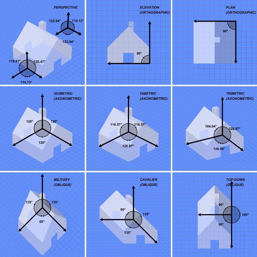
26 Orthographic projection Axonometric projection Isometric Projection-plane normal makes same angle with each principal axis There are just eight normal directions of this kind All three principal axes are equally foreshortened, good for getting measurements Principal axes make same angle in projection plane Alternative: dimetric & trimetric (general case) Machiraju/Zhang/Möller 26

27 Parallel Projection (4) Axonometric Projection - Isometric Angles between the projection of the axes are equal i.e. 120º Alternative - dimetric & trimetric Machiraju/Zhang/Möller 27

28 Types of Axonometric Projections Machiraju/Zhang/Möller 28
29 Oblique (parallel) projections Projectors are not normal to projection plane Most drawings in the text use oblique projection Machiraju/Zhang/Möller 29
30 Oblique projections Two angles are of interest: Angle α between the projector and projection plane The angle φ in the projection plane Derive the projection matrix Machiraju/Zhang/Möller 30
31 Derivation of oblique projections Machiraju/Zhang/Möller 31
32 Common oblique projections Cavalier projections Angle α = 45 degrees Preserves the length of a line segment perpendicular to the projection plane Angle φ is typically 30 or 45 degrees Cabinet projections Angle α = 63.7 degrees or arctan(2) Halves the length of a line segment perpendicular to the projection plane more realistic than cavalier Machiraju/Zhang/Möller 32
33 Machiraju/Zhang/Möller 33
34 Projections, continued Machiraju/Zhang/Möller 34
35 Perspective projections Mimics our human visual system or a camera Project in front of the center of projection Objects of equal size at different distances from the viewer will be projected at different sizes: nearer objects will appear bigger Machiraju/Zhang/Möller 35


36 Types of perspective projections Any set of parallel lines that are not parallel to the projection plane converges to a vanishing point, which corresponds to point at infinity in 3D One-, two-, three-point perspective views are based on how many principal axes are cut by projection plane Machiraju/Zhang/Möller 36
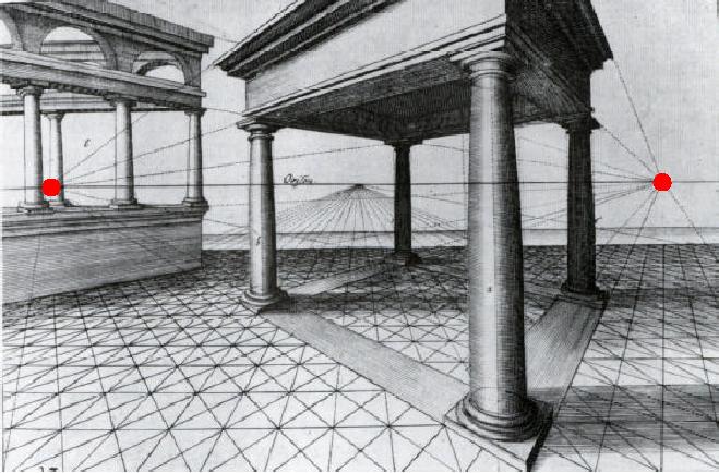
37 Vanishing points Machiraju/Zhang/Möller 37
38 Simple perspective projection COP at z = 0 Projection plane at z = d Transformation is not invertible or affine. Derive the projection matrix. Machiraju/Zhang/Möller 38
39 Simple perspective projection How to get a perspective projection matrix? Homogeneous coordinates come to the rescue Machiraju/Zhang/Möller 39
40 Summary of simple projections COP: origin of the coordinate system Look into positive z direction Projection plane perpendicular to z axis Machiraju/Zhang/Möller 40
41 Objectives What kind of camera we use? (pinhole) What projections make sense Orthographic Perspective The viewing pipeline Viewing in WebGL Shadows Machiraju/Zhang/Möller 41
Reading. Angel. Chapter 5. Optional
 Projections Reading Angel. Chapter 5 Optional David F. Rogers and J. Alan Adams, Mathematical Elements for Computer Graphics, Second edition, McGraw-Hill, New York, 1990, Chapter 3. The 3D synthetic camera
Transform 3D objects on to a 2D plane using projections
 PROJECTIONS 1 Transform 3D objects on to a 2D plane using projections 2 types of projections Perspective Parallel In parallel projection, coordinate positions are transformed to the view plane along parallel
Classical Viewing. Ed Angel Professor of Computer Science, Electrical and Computer Engineering, and Media Arts University of New Mexico
 Classical Viewing Ed Angel Professor of Computer Science, Electrical and Computer Engineering, and Media Arts University of New Mexico 1 Objectives Introduce the classical views Compare and contrast image
Introduction to Projection The art of representing a three-dimensional object or scene in a 2D space is called projection.
 Introduction to Projection The art of representing a three-dimensional object or scene in a 2D space is called projection. Projection is carried out by passing projectors through each vertex and intersecting
CS354 Computer Graphics Viewing and Projections
 Slide Credit: Donald S. Fussell CS354 Computer Graphics Viewing and Projections Qixing Huang February 19th 2018 Eye Coordinates (not NDC) Planar Geometric Projections Standard projections project onto
3D Viewing I. Acknowledgement: Some slides are from the Dr. Andries van Dam lecture. CMSC 435/634 August D Viewing I # /27
 3D Viewing I Acknowledgement: Some slides are from the Dr. Andries van Dam lecture. From 3D to 2D: Orthographic and Perspective Projection Part 1 Geometrical Constructions Types of Projection Projection
VIEWING 1. CLASSICAL AND COMPUTER VIEWING. Computer Graphics
 VIEWING We now investigate the multitude of ways in which we can describe our virtual camera. Along the way, we examine related topics, such as the relationship between classical viewing techniques and
Graphic Communications
 Graphic Communications Lecture 8: Projections Assoc. Prof.Dr. Cengizhan İpbüker İTÜ-SUNY 2004-2005 2005 Fall ipbuker_graph06 Projections The projections used to display 3D objects in 2D are called Planar
Projections Computer Graphics and Visualization
 Planar Geometric Fall 2010 Standard projections project onto a plane Projectors are lines that either converge at a center of projection are parallel Nonplanar projections are needed for applications such
Reading. Projections. The 3D synthetic camera model. Imaging with the synthetic camera. Angel. Chapter 5. Optional
 Reading Angel. Chapter 5 Optional Projections David F. Rogers and J. Alan Adams, Mathematical Elements for Computer Graphics, Second edition, McGraw-Hill, New York, 1990, Chapter 3. The 3D snthetic camera
CS475/CS675 Computer Graphics
 CS475/CS675 Computer Graphics Viewing Perspective Projection Projectors Centre of Projection Object Image Plane or Projection Plane 2 Parallel Projection Projectors Centre of Projection? Object Image Plane
Introduction to Computer Graphics (CS602) Lecture 19 Projections
 Lecture 19 Projections") Introduction to Computer Graphics (CS602) Lecture 19 Projections For centuries, artists, engineers, designers, drafters, and architects have been facing difficulties and constraints imposed by the problem
Introduction to Computer Graphics (CS602) Lecture 19 Projections For centuries, artists, engineers, designers, drafters, and architects have been facing difficulties and constraints imposed by the problem
3D COMPUTER GRAPHICS
 3D COMPUTER GRAPHICS http://www.tutorialspoint.com/computer_graphics/3d_computer_graphics.htm Copyright tutorialspoint.com In the 2D system, we use only two coordinates X and Y but in 3D, an extra coordinate
Interactive Computer Graphics A TOP-DOWN APPROACH WITH SHADER-BASED OPENGL
 International Edition Interactive Computer Graphics A TOP-DOWN APPROACH WITH SHADER-BASED OPENGL Sixth Edition Edward Angel Dave Shreiner 228 Chapter 4 Viewing Front elevation Elevation oblique Plan oblique
Projections. Conceptual Model of the 3D viewing process
 Projections Projections Conceptual Model of the 3D viewing process 3D Projections (Rays converge on eye position) (Rays parallel to view plane) Perspective Parallel Orthographic Oblique Elevations Axonometric
3D Viewing I. From 3D to 2D: Orthographic and Perspective Projection Part 1
 From 3D to 2D: Orthographic and Perspective Projection Part 1 3D Viewing I By Andries van Dam Geometrical Constructions Types of Projection Projection in Computer Graphics Jian Chen January 15, 2010 3D
3D Viewing. Projections. Perspective A B B. Projectors. Center of Projection. Projection Plane
 Projections Projectors A Center of Projection A B B Projection Plane Perspective Projections Projectors A A B At Infinit B Projection Plane Parallel Parallel Projections Orthographic 3D Viewing Top View
Exploring 3D in Flash
 1 Exploring 3D in Flash We live in a three-dimensional world. Objects and spaces have width, height, and depth. Various specialized immersive technologies such as special helmets, gloves, and 3D monitors
Visual Imaging in the Electronic Age. Drawing Perspective Images
 Visual Imaging in the Electronic Age Lecture # 2 Drawing Perspective Images Brunelleschi s Experiment August 27, 2015 Prof. Donald P. Greenberg http://www.graphics.cornell.edu/academic/art2907/ User Name:
Lecture 2 of 41. Viewing 1 of 4: Overview, Projections
 Viewing 1 of 4: Overview, Projections William H. Hsu Department of Computing and Information Sciences, KSU KSOL course pages: http://bit.ly/hgvxlh / http://bit.ly/evizre Public mirror web site: http://www.kddresearch.org/courses/cis636
Lecture 2 of 41. Viewing 1 of 4: Overview, Projections
 Viewing 1 of 4: Overview, Projections William H. Hsu Department of Computing and Information Sciences, KSU KSOL course pages: http://bit.ly/hgvxlh / http://bit.ly/evizre Public mirror web site: http://www.kddresearch.org/courses/cis636
Visual Imaging in the Electronic Age. Drawing Perspective Images
 Visual Imaging in the Electronic Age Lecture # 2 Drawing Perspective Images Brunelleschi s Experiment August 25, 2016 Prof. Donald P. Greenberg http://www.graphics.cornell.edu/academic/art2907/ User Name:
Projections Josef Pelikán & Alexander Wilkie CGG MFF UK Praha
 Projections 995-205 Josef Pelikán & Aleander Wilkie CGG MFF UK Praha pepca@cgg.mff.cuni.c http://cgg.mff.cuni.c/~pepca/ / 24 Basic Concepts plane of projection projection ras projection origin plane of
Reading. 8. Projections. 3D Geometry Pipeline. 3D Geometry Pipeline (cont d) Required: w Watt, Section
 Required: w Watt, Section") Reading Required: Watt, Section 5.2.2 5.2.4. Further reading: 8. Projections Fole, et al, Chapter 5.6 and Chapter 6 David F. Rogers and J. Alan Adams, Mathematical Elements for Computer Graphics, 2 nd
Reading Required: Watt, Section 5.2.2 5.2.4. Further reading: 8. Projections Fole, et al, Chapter 5.6 and Chapter 6 David F. Rogers and J. Alan Adams, Mathematical Elements for Computer Graphics, 2 nd
ENGINEERING GRAPHICS 1E9
 Lecture 3 Monday, 15 December 2014 1 ENGINEERING GRAPHICS 1E9 Lecture 3: Isometric Projections Lecture 3 Monday, 15 December 2014 2 What is ISOMETRIC? It is a method of producing pictorial view of an object
Visual Imaging in the Electronic Age. Drawing Perspective Images
 Visual Imaging in the Electronic Age Lecture # 2 Drawing Perspective Images Brunelleschi s Experiment August 24, 2017 Prof. Donald P. Greenberg http://www.graphics.cornell.edu/academic/art2907/ User Name:
AML710 CAD LECTURE Parallel Projections a) Orthographic Projections b) Axonometric Projections 2. Perspective Transformations and Projections
 Orthographic Projections b) Axonometric Projections 2. Perspective Transformations and Projections") AML7 CAD LECTURE 8 PROJECTIONS. Parallel Projections a) Orthographic Projections b) Aonometric Projections. Perspective Transormations and Projections PROJECTIONS Aine, Rigid-bod/Euclidian Vs Perspective
AML7 CAD LECTURE 8 PROJECTIONS. Parallel Projections a) Orthographic Projections b) Aonometric Projections. Perspective Transormations and Projections PROJECTIONS Aine, Rigid-bod/Euclidian Vs Perspective
I B.TECH- I SEMESTER DEPARTMENT OF MECHANICAL ENGINEERING ENGINEERING DRAWING
 I B.TECH- I SEMESTER DEPARTMENT OF MECHANICAL ENGINEERING ENGINEERING DRAWING ENGINEERING DRAWING UNIT-V DEFINITIONS: Axonometric Trimetric Dimetric Isometric It is a parallel technique used to create
Reading. Projections. Projections. Perspective vs. parallel projections. Foley et al. Chapter 6. Optional. Perspective projections pros and cons:
 Reading Fole et al. Chapter 6 Optional Projections David F. Rogers and J. Alan Adams, Mathematical Elements for Computer Graphics, Second edition, McGra-Hill, Ne York, 990, Chapter 3. Projections Projections
1. When sketching long, narrow objects in OBLIQUE, distortion can be lessened by placing the long dimension along:
 Draft Student Name: Teacher: District: Date: Wake County Test: 9_12 T and I IC61 - Drafting I Test 2 Description: 3.03 Apply 3D sketching Form: 501 1. When sketching long, narrow objects in OBLIQUE, distortion
Perspective. Cornell CS4620/5620 Fall 2012 Lecture Kavita Bala 1 (with previous instructors James/Marschner)
") CS4620/5620: Lecture 6 Perspective 1 Announcements HW 1 out Due in two weeks (Mon 9/17) Due right before class Turn it in online AND in class (preferably) 2 Transforming normal vectors Transforming surface
CS4620/5620: Lecture 6 Perspective 1 Announcements HW 1 out Due in two weeks (Mon 9/17) Due right before class Turn it in online AND in class (preferably) 2 Transforming normal vectors Transforming surface
History of projection. Perspective. History of projection. Plane projection in drawing
 History of projection Ancient times: Greeks wrote about laws of perspective Renaissance: perspective is adopted by artists Perspective CS 4620 Lecture 3 Duccio c. 1308 1 2 History of projection Plane projection
Perspective. Announcement: CS4450/5450. CS 4620 Lecture 3. Will be MW 8:40 9:55 How many can make the new time?
 Perspective CS 4620 Lecture 3 1 2 Announcement: CS4450/5450 Will be MW 8:40 9:55 How many can make the new time? 3 4 History of projection Ancient times: Greeks wrote about laws of perspective Renaissance:
11/12/2015 CHAPTER 7. Axonometric Drawings (cont.) Axonometric Drawings (cont.) Isometric Projections (cont.) 1) Axonometric Drawings
 Axonometric Drawings (cont.) Isometric Projections (cont.) 1) Axonometric Drawings") CHAPTER 7 1) Axonometric Drawings 1) Introduction Isometric & Oblique Projection Axonometric projection is a parallel projection technique used to create a pictorial drawing of an object by rotating the
CHAPTER 7 1) Axonometric Drawings 1) Introduction Isometric & Oblique Projection Axonometric projection is a parallel projection technique used to create a pictorial drawing of an object by rotating the
(Ans:d) a. A0 b. A1 c. A2 d. A3. (Ans:b) (Ans:a) (Ans:d) (Ans:d)
 a. A0 b. A1 c. A2 d. A3. (Ans:b) (Ans:a) (Ans:d) (Ans:d)") Multiple Choice Questions (MCQ) on Engineering Drawing (Instruments) The mini drafter serves the purpose of everything except a. Scales b. Set square c. Protractor d. Compass (Ans:d) During operation,
Multiple Choice Questions (MCQ) on Engineering Drawing (Instruments) The mini drafter serves the purpose of everything except a. Scales b. Set square c. Protractor d. Compass (Ans:d) During operation,
UNIT 5a STANDARD ORTHOGRAPHIC VIEW DRAWINGS
 UNIT 5a STANDARD ORTHOGRAPHIC VIEW DRAWINGS 5.1 Introduction Orthographic views are 2D images of a 3D object obtained by viewing it from different orthogonal directions. Six principal views are possible
PROJECTIONS PARALLEL CONICAL PROJECTIONS PROJECTIONS OBLIQUE ORTHOGRAPHIC PROJECTIONS PROJECTIONS
 PROJECTIONS CONICAL PROJECTIONS PARALLEL PROJECTIONS OBLIQUE PROJECTIONS ORTHOGRAPHIC PROJECTIONS ISOMETRIC MULTI-VIEW an object; The Description of Forms Behind every drawing of an object is space relationship
ENGINEERING DRAWING. 1. Set squares are used to draw different angles. What is the angel a formed by the 45⁰ set square? Give a brief answer.
 ENGINEERING DRAWING 1. Set squares are used to draw different angles. What is the angel a formed by the 45⁰ set square? Give a brief answer. 2. Which is the correct method of hatching a plane surface?
Perspective in 2D Games
 Lecture 16 in 2D Games Drawing Images Graphics Lectures SpriteBatch interface Coordinates and Transforms bare minimum to draw graphics Drawing Camera Projections side-scroller vs. top down Drawing Primitives
Chapter 5 Pictorial sketching
 Chapter 5 Pictorial sketching Contents Freehand sketching techniques Pictorial projections - Axonometric - Oblique Isometric projection vs isometric sketch Isometric sketch from an orthographic views Isometric
60 Most Important Engineering Drawing Questions
 1. If a client of yours is having difficulty visualizing a design, what type of drawing would be the easiest to understand? A. axonometric B. three-view orthographic C. one-view orthographic D. bimetric
Graphics and Interaction Perspective Geometry
 433-324 Graphics and Interaction Perspective Geometr Department of Computer Science and Software Engineering The Lecture outline Introduction to perspective geometr Perspective Geometr Centre of projection
Beginning Engineering Graphics 3 rd Week Lecture Notes Instructor: Edward N. Locke Topic: The Coordinate System, Types of Drawings and Orthographic
 Beginning Engineering Graphics 3 rd Week Lecture Notes Instructor: Edward N. Locke Topic: The Coordinate System, Types of Drawings and Orthographic 1 st Subject: The Cartesian Coordinate System The Cartesian
CS123 INTRODUCTION TO COMPUTER GRAPHICS. Viewing. Part I (History and Overview of Projections) Andries van Dam 1 / 46 10/05/2017
 Andries van Dam 1 / 46 10/05/2017") Viewing Part I (History and Overview of Projections) 1 / 46 Lecture Topics History of projection in art Geometric constructions Types of projection (parallel and perspective) 2 / 46 CS123 INTRODUCTION
Viewing Part I (History and Overview of Projections) 1 / 46 Lecture Topics History of projection in art Geometric constructions Types of projection (parallel and perspective) 2 / 46 CS123 INTRODUCTION
Viewing. Perspective views. Parallel l views. Finite COP (center of projection) COP at infinity DOP (direction of projection) Parallel View
 COP at infinity DOP (direction of projection) Parallel View") Viewing 3 r Week, 29 Funamental Tes of Viewing views Finite COP (center of rojection) Parallel l views COP at infinit DOP (irection of rojection) View Parallel View Parallel View View Taonom of Planar
Viewing 3 r Week, 29 Funamental Tes of Viewing views Finite COP (center of rojection) Parallel l views COP at infinit DOP (irection of rojection) View Parallel View Parallel View View Taonom of Planar
CS337 INTRODUCTION TO COMPUTER GRAPHICS. Viewing. Part I (History and Overview of Projections) Bin Sheng 1 / 46 10/04/2016
 Bin Sheng 1 / 46 10/04/2016") Viewing Part I (History and Overview of Projections) 1 / 46 Lecture Topics History of projection in art Geometric constructions Types of projection (parallel and perspective) 2 / 46 CS337 INTRODUCTION
Viewing Part I (History and Overview of Projections) 1 / 46 Lecture Topics History of projection in art Geometric constructions Types of projection (parallel and perspective) 2 / 46 CS337 INTRODUCTION
Peter Clements Art Studios
 Peter Clements Art Studios How to Erase Pencil Axonometric Projection or drawing is referred to as a projection as they do not have vanishing points as the conventional perspective drawing. Consequently,
Student Name: Teacher: Date: District: Rowan. Assessment: 9_12 T and I IC61 - Drafting I Test 1. Description: Unit C - Sketching - Test 2.
 Student Name: Teacher: Date: District: Rowan Assessment: 9_12 T and I IC61 - Drafting I Test 1 Description: Unit C - Sketching - Test 2 Form: 501 1. The most often used combination of views includes the:
Multiviews and Auxiliary Views
 Multiviews and Auxiliary Views Multiviews and Auxiliary Views Objectives Explain orthographic and multiview projection. Identifying the six principal views. Apply standard line practices to multiviews
Isometric Drawing Chapter 26
 Isometric Drawing Chapter 26 Sacramento City College EDT 310 EDT 310 - Chapter 26 - Isometric Drawing 1 Drawing Types Pictorial Drawing types: Perspective Orthographic Isometric Oblique Pictorial - like
Isometric Projection Drawing CHAPTER 6
 Isometric Projection Drawing CHAPTER 6 Content Overview Pictorial projection Parallel projection Axonometric projection Isometric projection Axes and selection Isometric lines and planes Isometric scale
Bridge Course On Engineering Drawing for Mechanical Engineers
 G. PULLAIAH COLLEGE OF ENGINEERING AND TECHNOLOGY Accredited by NAAC with A Grade of UGC, Approved by AICTE, New Delhi Permanently Affiliated to JNTUA, Ananthapuramu (Recognized by UGC under 2(f) and 12(B)
Perspective in 2D Games
 Lecture 15 in 2D Games Drawing Images Graphics Lectures SpriteBatch interface Coordinates and Transforms bare minimum to draw graphics Drawing Camera Projections side-scroller vs. top down Drawing Primitives
Viewing. Perspective views. Parallel l views. Finite COP (center of projection) COP at infinity DOP (direction of projection) Parallel View
 COP at infinity DOP (direction of projection) Parallel View") Viewing th Week, 29 Funamental Tes of Viewing views Finite COP (center of rojection) Parallel l views COP at infinit DOP (irection of rojection) View Parallel View Parallel View View Classical Viewing
Viewing th Week, 29 Funamental Tes of Viewing views Finite COP (center of rojection) Parallel l views COP at infinit DOP (irection of rojection) View Parallel View Parallel View View Classical Viewing
How do we see the world?
 The Camera 1 How do we see the world? Let s design a camera Idea 1: put a piece of film in front of an object Do we get a reasonable image? Credit: Steve Seitz 2 Pinhole camera Idea 2: Add a barrier to
Perspective. CS 4620 Lecture Steve Marschner. Cornell CS4620 Spring 2018 Lecture 5
 Perspective CS 4620 Lecture 5 2018 Steve Marschner 1 Parallel projection To render an image of a 3D scene, we project it onto a plane Simplest kind of projection is parallel projection image projection
2. Line composed of closely and evenly spaced short dashes in a drawing represents
 1. Hidden lines are drawn as (a) dashed narrow lines (b) dashed wide lines (c) long-dashed dotted wide line (d) long-dashed double dotted wide line Ans: (a) 2. Line composed of closely and evenly spaced
IMAGE FORMATION. Light source properties. Sensor characteristics Surface. Surface reflectance properties. Optics
 IMAGE FORMATION Light source properties Sensor characteristics Surface Exposure shape Optics Surface reflectance properties ANALOG IMAGES An image can be understood as a 2D light intensity function f(x,y)
Dr. Reham Karam. Perspective Drawing. For Artists & Designers. By : Dr.Reham Karam
 Perspective Drawing For Artists & Designers By : Dr.Reham Karam Geometry and Art : What is perspective? Perspective, in the vision and visual perception, is : the way that objects appear to the eye based
Graphical Communication for Engineering ENSC 204 Final Exam
 Name: Student #: Graphical Communication for Engineering ENSC 204 Final Exam December 16, 2015 Time: 3 hours CLOSED BOOK EXAM Read all the instructions below. Do NOT start the exam until you are told to.
DMT113 Engineering Drawing. Chapter 3 Stretch System
 DMT113 Engineering Drawing Chapter 3 Stretch System Contents Theory & Multiview Planes 6 Principle Views Multiview Sketching Technique & Perspective First & Third Angle Multiview Representations Theory
Drawing: technical drawing TECHNOLOGY
 Drawing: technical drawing Introduction Humans have always used images to communicate. Cave paintings, some of which are over 40,000 years old, are the earliest example of this artistic form of communication.
Image Formation. Light from distant things. Geometrical optics. Pinhole camera. Chapter 36
 Light from distant things Chapter 36 We learn about a distant thing from the light it generates or redirects. The lenses in our eyes create images of objects our brains can process. This chapter concerns
Perspective in 2D Games
 Lecture 16 in 2D Games Take Away for Today What is game camera? How does it relate to screen space? Object space? How does camera work in a 2D game? 3D? How do we give 2D games depth? Advantages, disadvantages
1 st Subject: Types of Pictorial Drawings (Isometric, Oblique, and Perspective)
") Intermediate Engineering Graphics 4 th Week 1 st Meeting Lecture Notes Instructor: Edward N. Locke Topic: Types of pictorial drawings (isometric, oblique, and perspective), isometric sketching and drafting
Intermediate Engineering Graphics 4 th Week 1 st Meeting Lecture Notes Instructor: Edward N. Locke Topic: Types of pictorial drawings (isometric, oblique, and perspective), isometric sketching and drafting
Chapter 5 Pictorial Projection
 Chapter 5 Pictorial Projection Objectives After completing this chapter, the students will be able to Create freehand sketches using the correct sketching techniques. Explainthe difference between axonometric
Engineering Drawing Lecture 5 PROJECTION THEORY
 University of Palestine College of Engineering & Urban Planning First Level Engineering Drawing Lecture 5 PROJECTION THEORY Lecturer: Eng. Eman Al.Swaity Eng.Heba hamad PART 1 PROJECTION METHOD TOPICS
Chapter 36. Image Formation
 Chapter 36 Image Formation Real and Virtual Images Real images can be displayed on screens Virtual Images can not be displayed onto screens. Focal Length& Radius of Curvature When the object is very far
 Visual Arts TANGENCIES Two figures are tangents when they have only one point in common, called the point of tangency. Types of tangencies. There are tangencies between circumferences or between straight
Unit 1: Image Formation
 Unit 1: Image Formation 1. Geometry 2. Optics 3. Photometry 4. Sensor Readings Szeliski 2.1-2.3 & 6.3.5 1 Physical parameters of image formation Geometric Type of projection Camera pose Optical Sensor
Multiview Drawing. Definition: Graphical representation of a 3- dimensional object on one plane (sheet of paper) using two or more views.
 using two or more views.") Multiview Drawing Definition: Graphical representation of a 3- dimensional object on one plane (sheet of paper) using two or more views. Multiview Drawing Another name for multiview drawing is orthographic
Multiview Drawing Definition: Graphical representation of a 3- dimensional object on one plane (sheet of paper) using two or more views. Multiview Drawing Another name for multiview drawing is orthographic
Understanding Projection Systems
 Understanding Projection Systems A Point: A point has no dimensions, a theoretical location that has neither length, width nor height. A point shows an exact location in space. It is important to understand
Lenses. Images. Difference between Real and Virtual Images
 Linear Magnification (m) This is the factor by which the size of the object has been magnified by the lens in a direction which is perpendicular to the axis of the lens. Linear magnification can be calculated
Extension material for Level 2 Design and Visual Communication Study Guide
 3-D formal drawing Extension material for Level 2 Design and Visual Communication Study Guide ISBN 978-1-927194-15-7 For individual student use only. No other use permitted. ESA Publications (NZ) Ltd,
Chapter 2. Isometric Projection and Multi View Drawings. Below are the desired outcomes and usage competencies based on the completion of Chapter 2.
 Chapter 2 Below are the desired outcomes and usage competencies based on the completion of Chapter 2. Desired Outcomes: Understand Isometric Projection and 2D sketching. Knowledge of additional Projection
Spherical Mirrors. Concave Mirror, Notation. Spherical Aberration. Image Formed by a Concave Mirror. Image Formed by a Concave Mirror 4/11/2014
 Notation for Mirrors and Lenses Chapter 23 Mirrors and Lenses The object distance is the distance from the object to the mirror or lens Denoted by p The image distance is the distance from the image to
History of projection
 History of projection Ancient times: Greeks wrote about laws of perspective Renaissance: perspective is adopted by artists Duccio c. 1308 History of projection Later Renaissance: perspective formalized
Engineering Graphics with SOLIDWORKS 2016 and Video Instruction
 Engineering Graphics with SOLIDWORKS 2016 and Video Instruction A Step-by-Step Project Based Approach David C. Planchard, CSWP, SOLIDWORKS Accredited Educator SDC PUBLICATIONS Better Textbooks. Lower Prices.
Lecture 02 Image Formation 1
 Institute of Informatics Institute of Neuroinformatics Lecture 02 Image Formation 1 Davide Scaramuzza http://rpg.ifi.uzh.ch 1 Lab Exercise 1 - Today afternoon Room ETH HG E 1.1 from 13:15 to 15:00 Work
CE 100 Civil Engineering Drawing Sessional (Lab Manual)
") CE 100 Civil Engineering Drawing Sessional (Lab Manual) Department of Civil Engineering Ahsanullah University of Science and Technology November, 2017 1 Preface This course is designed to provide civil
CE 100 Civil Engineering Drawing Sessional (Lab Manual) Department of Civil Engineering Ahsanullah University of Science and Technology November, 2017 1 Preface This course is designed to provide civil
Lecture #4 MULTIVIEW PROJECTION RES 112E COMPUTER AIDED TECHNICAL DRAWING ITU
 Lecture #4 MULTIVIEW PROJECTION This week You will learn multi-view projection. The steps to follow are: Projections (ISO-E & ISO-A) Multi-view drawings Views (Basic,Auxiliary, Detailed etc.) Sketching
ORTHOGRAPHIC PROJECTION
 ORTHOGRAPHIC PROJECTION C H A P T E R S I X OBJECTIVES 1. Recognize and the symbol for third-angle projection. 2. List the six principal views of projection. 3. Understand which views show depth in a drawing
MULTIPLE CHOICE QUESTIONS - CHAPTER 6
 MULTIPLE CHOICE QUESTIONS - CHAPTER 6 1. The selection of the front view in executing a multiview drawing of an object is dependent upon the following factors: a. size and shape of the object and their
Engineering Graphics with SolidWorks 2012
 INSIDE: Video Instruction DVD An audio/visual presentation of the tutorial projects Engineering Graphics with SolidWorks 2012 and Video Instruction DVD A Step-by-Step Project Based Approach Introductory
Dr F. Cuzzolin 1. September 29, 2015
 P00407 Principles of Computer Vision 1 1 Department of Computing and Communication Technologies Oxford Brookes University, UK September 29, 2015 September 29, 2015 1 / 73 Outline of the Lecture 1 2 Basics
Lenses. A lens is any glass, plastic or transparent refractive medium with two opposite faces, and at least one of the faces must be curved.
 PHYSICS NOTES ON A lens is any glass, plastic or transparent refractive medium with two opposite faces, and at least one of the faces must be curved. Types of There are two types of basic lenses. (1.)
Cameras. CSE 455, Winter 2010 January 25, 2010
 Cameras CSE 455, Winter 2010 January 25, 2010 Announcements New Lecturer! Neel Joshi, Ph.D. Post-Doctoral Researcher Microsoft Research neel@cs Project 1b (seam carving) was due on Friday the 22 nd Project
Projection. Announcements. Müller-Lyer Illusion. Image formation. Readings Nalwa 2.1
 Announcements Mailing list (you should have received messages) Project 1 additional test sequences online Projection Readings Nalwa 2.1 Müller-Lyer Illusion Image formation object film by Pravin Bhat http://www.michaelbach.de/ot/sze_muelue/index.html
CS-184: Computer Graphics. Today
 CS-84: Computer Graphics Lecture 5: Projection Prof. James O Brien Universit of California, Berkele V25-5-.3 Toda Windowing and Viewing Transformations Windows and viewports Orthographic projection Perspective
Two strategies for realistic rendering capture real world data synthesize from bottom up
 Recap from Wednesday Two strategies for realistic rendering capture real world data synthesize from bottom up Both have existed for 500 years. Both are successful. Attempts to take the best of both world
Chapter 8. Technical Drawings
 Chapter 8 Technical Drawing Technical Drawings Multiview drawings Also called three-view drawings Simple objects take three views Front, top, one side Title block Identifies who did the design Gives date,
Chapter 23. Mirrors and Lenses
 Chapter 23 Mirrors and Lenses Notation for Mirrors and Lenses The object distance is the distance from the object to the mirror or lens Denoted by p The image distance is the distance from the image to
10.2 Images Formed by Lenses SUMMARY. Refraction in Lenses. Section 10.1 Questions
 10.2 SUMMARY Refraction in Lenses Converging lenses bring parallel rays together after they are refracted. Diverging lenses cause parallel rays to move apart after they are refracted. Rays are refracted
Chapter 23. Mirrors and Lenses
 Chapter 23 Mirrors and Lenses Notation for Mirrors and Lenses The object distance is the distance from the object to the mirror or lens Denoted by p The image distance is the distance from the image to
Orthographic Projection
 ENG3000 Orthographic Projection 1 Session Objectives To understand the basic principles of orthographic projection To be able to construct orthographic views of simple objects To visualize 3 D objects
Complete the diagram to show what happens to the rays. ... (1) What word can be used to describe this type of lens? ... (1)
 What word can be used to describe this type of lens? ... (1)") Q1. (a) The diagram shows two parallel rays of light, a lens and its axis. Complete the diagram to show what happens to the rays. (2) Name the point where the rays come together. (iii) What word can be
Q1. (a) The diagram shows two parallel rays of light, a lens and its axis. Complete the diagram to show what happens to the rays. (2) Name the point where the rays come together. (iii) What word can be
Pictorial Drawings. DFTG-1305 Technical Drafting Prepared by Francis Ha, Instructor
 DFTG-1305 Technical Drafting Prepared by Francis Ha, Instructor Pictorial Drawings Geisecke s textbook for reference: 14 th Ed. Ch. 15: p. 601 Ch. 16: p. 620 15 th Ed. Ch. 14: p. 518 Ch. 15: p. 552 Update:
technical drawing school of art, design and architecture sarah adeel nust spring 2011
 technical drawing school of art, design and architecture sarah adeel nust spring 2011 the ability to document imagination. a mean to design reasoning spring 2011 perspective drawings technical drawing
Chapter 23. Mirrors and Lenses
 Chapter 23 Mirrors and Lenses Mirrors and Lenses The development of mirrors and lenses aided the progress of science. It led to the microscopes and telescopes. Allowed the study of objects from microbes
Lens Principal and Nodal Points
 Lens Principal and Nodal Points Douglas A. Kerr, P.E. Issue 3 January 21, 2004 ABSTRACT In discussions of photographic lenses, we often hear of the importance of the principal points and nodal points of