Welcome. Hong Kong Zhuhai Macao Bridge Design & Construction of Marine Viaducts for HKLR
|
|
|
- Edwin Garrison
- 5 years ago
- Views:
Transcription


1 Welcome Hong Kong Zhuhai Macao Bridge Design & Construction of Marine Viaducts for HKLR HKSAR Government, Highways Department s Contract HY/2011/09 Hong Kong Zhuhai Macao Bridge Hong Kong Link Road 1


2 Contents 1. HZMB Project Overview 2. Design Challenges a. Bridge Span Configuration b. Precast Shells for Pile Caps c. Prestressed Piers & Monolithic Pier Deck Connection d. RC Piers & Monolithic Pier Deck Connection 3. Construction Challenges a. Marine Bored Piling b. Precast Concrete Shell for Marine Pile Caps c. Precast & In situ Piers d. Segmental Deck Casting & Erection e. Other Deck Construction Activities 4. Project Status HKLR 2 09
3 HZMB Project Overview
 Transport Department Electrical & Mechanical Services Department Civil Engineering")
4 Employer The Government of HKSAR Administrated by Highways Department HZMB Project Management Office Supervising Officer Ove Arup & Partners Key stakeholders: Maintenance Highways Department NTW Region Office Design Highways Department (Bridges and Structures/ Geotechnical Advisory Unit/ Lighting Division) Transport Department Electrical & Mechanical Services Department Civil Engineering Development Department Marine Traffic, Design & Management Marine Department Working in vicinity of Airport Airport Authority Civil Aviation Department Design and Build Contractor Dragages-China Harbour-VSL Joint Venture Environmental Protection Environmental Protection Department Environmental Protection Highways Department ENPO
5 Design and Build Contractor Design Team: Designer YWL Engineering Pte Ltd Designer Mott MacDonald Hong Kong Technical supports Bouygues Travaux Publics Supported by: Geotechnical supports Golder Associates Marine traffic consultant BMT Asia Pacific Major segment erection equipment design VSL Technical Centre Asia (TCA) Environmental Team Leader Cinotech Consultants Design Checker AECOM Asia


6 Hong Kong Zhuhai Macao Bridge Tuen Mun Western Bypass Tuen Mun Chek Lap Kok Link Hong Kong Zhuhai Macao Bridge (HZMB) Main Bridge Hong Kong Link Road Hong Kong Boundary Crossing Facility 6


7 Con. Sum HK$ bn Length 9.4 km viaducts Start 31 May 2012 Deck 5,714 segments Lanes dual 3 lanes; 100kph Concrete 620,000 m 3 Span 75m (typ) to 180m Steel 180,000 tonnes Piles 725 nrs Headland between San Shek Wan & Sha Lo Wan Hong Kong International Airport Interface with HZMB Main Bridge at P0 Western Waters Land Section (Airport Island) Hong Kong Boundary Crossing Facility Turnaround Facility P52 to P60 Navigation Channel P16 to P21 Airport Channel Land Viaduct connected with abutment at Scenic Hill Lantau Island
8 Design Challenges
9 Design Challenges Durability 120-year Design Life Design Concrete Grade Reinforcement Increase concrete cover Crack width control PFA/CSF Low w/c ratio Stainless steel to 1 st layer at tidal & splash zones

 Pile Length from 7m to more than 100m 36 friction pile for very deep")


10 Design Challenges Viaduct Design Complex Geology Longest 180m span Marine Conditions & Tight Schedule Airport Environment Large dia. end bearing bored pile (2.3m, 2.5m & 2.8m) Pile Length from 7m to more than 100m 36 friction pile for very deep bedrock of over 100m 10m height pier segments (SOP) Cross Beam for resisting transverse moment 3 pieces for long span SOP Precast pile cap shell design Precast pier design Precast deck & cross beam shell design Segment design to suit erection equipment under Airport Height Restriction (AHR) Long Span Viaduct at Western Waters (110m + 150m x m)


11 Design Challenges Seismic Design Seismic parameters: 1st extensive application for bridge design in Hong Kong No Damage Requirement Repairable Damage Requirement No Collapse Requirement
12 Seismic Design Design according to Eurocode 8 Parts 1, 2 & 5 first extensive application in bridge design in Hong Kong The two fundamental performance requirement are revised and extended to three performance requirements: GROUND TYPE ACC. TO TABLE 3.1 OF EN :2004 (E) Location Ground Type Soil factor (S) Western Waters Type S1 1.8 Head Land Type B 1.2 Airport Channel Type A, E or D 1.0, 1.4 or 1.35 Land Type A, B, C or D 1.0, 1.2, 1.15 or No Damage Requirement (T = 120 yr) 2. Repairable Damage Requirement (T = 475 yr) 3. No Collapse Requirement (T = 2,475 yr) Peak ground acceleration follows that reported in GEO Report No. 65 Seismic Hazard Analysis of the Hong Kong Region Seismic load obtained from dynamic seismic analysis Typical Plot for Type A Ground Horizontal Response Spectrum 12


13 Seismic Design Seismic Design Features Concept SLS Seismic loading on bearings for typical 75m span bridges: o Max Vertical load = ~ 25,000kN o Max Horizontal load = ~1,500kN Vertical loads to be resisted by bearings Thrust block and bearings system to resist transverse seismic force Bearings to allow bridges free to move under normal service and SLS seismic conditions Guided Bearing Concrete Thrust Block Typical Pier Head Arrangement for Marine Viaducts 13


14 Seismic Design Thrust Block Arrangement for Marine Viaducts 14
15 Bridge Span Configuration 15
16 Bridge Span Configuration S/N Bridge Unit Span Configuration (m) Length of bridge unit (m) Typical Deck width between parapets (m) 1 2 Typical-Span Units (Pier P0 to P16, P21 to P53 & P59 to P67) at Western Waters Navigation Channel Unit (Piers P16 to P21) at Western Waters 8 x 75m (Typ.) x Turnaround Facility Unit (Piers P53 to P59) 6x General Airport Channel Units (Piers P70 to P78) 109+2x x Headland & Navigation Units at Airport Channel (Piers P67 to P70 & P78 to P84) / or Land Units (Piers P84 to Abutment-P115) Various span lengths from 35m to 65m 208 to

17 Bridge Span Configuration Bearing Monolithic Airport Height Restriction Bearing Typical Span Units at Western Waters (Typical 8x75) 4m 17
18 Bridge Span Configuration Monolithic Airport Height Restriction Bearing Bearing Navigation Channel Unit at Western Waters (109+3X ) Box depth=4.0~7.936m 18


 Box")
19 Bridge Span Configuration Turnaround Facility at Western Waters (6X70) Box depth =4.0m 19
 Airport Height Restriction Bearing Monolithic")
 Box depth=4.0~8.")
20 Bridge Span Configuration Typical Units at Airport Channel (109+2x ) Airport Height Restriction Bearing Monolithic Bearing Headland & Navigation Units at Airport Channel ( /100) Box depth=4.0~8.862m Bearing Monolithic Bearing Box depth=4.0~10.0m 20
21 Precast Shells for Pile Caps 21
22 Precast Shells for Pile Caps Western Waters (emerged pile caps): Traditional Way : Using steel formwork for repetitive casting of pile caps over water Innovative Way : Precast concrete cap shells as formwork and permanent protection 220T (typical) to largest 500T + Infill with cast in-situ reinforced concrete 22


23 Precast Shell for Pile Caps Precast Shell Type CP1 (for Typical Spans) Precast Shell Type CP4 Precast Shell Type F1 Precast Shell Type CP11 23


24 Precast Shell for Pile Caps Concrete inside precast shells Thermal Analysis Model for Casting of Pile Cap 24

25 Precast Shell for Pile Caps Precast Concrete Shell for Pile Cap Construction Thermal strains may induce high tensile stresses and thus cracks Use of reinforcement to control these cracks not effective Instead, special isolation material proposed to minimize thermal effects on precast shell Separation material properties: Thin layer of compressible material Low stiffness modulus Low thermal conductivity Adequate strength to transfer wet concrete pressure to shell Used along shell walls and base slab (except pile top areas) 25


26 Precast Shell for Pile Caps Precast Concrete Shell for Pile Cap Construction 26
27 Prestressed Piers & Monolithic Pier-Deck Connection 27


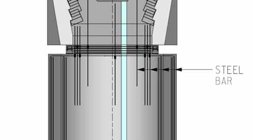
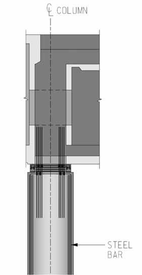
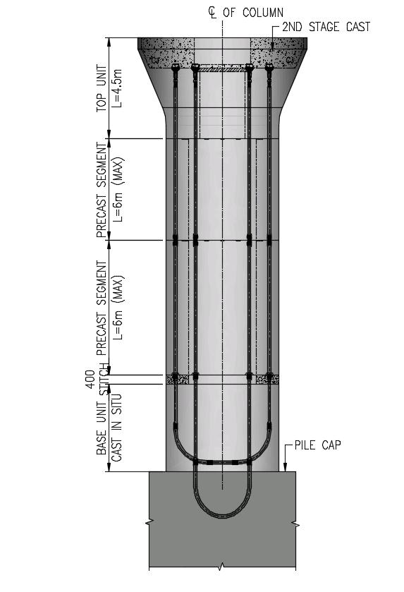
28 Prestressed Piers & Monolithic Pier-Deck Connection Precast Pier Analysis Precast Piers from P2 to P44 for Bridges ML 01 to ML06 First joint located approx. 1.5m above splash zone with in-situ RC concrete Standard Precast Pier Units = 3m or 6m and 4.5m for Pier Head Units Total Precast Pier Units = around 300 units (for both left & right bridges) 28
29 Prestressed Piers & Monolithic Pier-Deck Connection Prestressed Pier at Western Waters 29

30 Prestressed Piers & Monolithic Pier-Deck Connection 30

31 RC Piers & Monolithic Pier-Deck Connection 31

32 RC Piers & Monolithic Pier-Deck Connection 32

33 RC Piers & Monolithic Pier-Deck Connection Special connections Precast Segment B Cast In situ Diaphragm 33
34 Friction Bored Pile 34
35 Shaft Grouted Friction Piles and Pile Testing Friction Piles Engineering Rock Head levels found to be deeper for some piers Pier Pier 4 Pier 16 Engineering Rock Head Level 100 mpd 141 mpd* Presence of Corestone/Mixed hard Rock condition in the deeper level No rock encountered above -100 mpd in Borehole P-16-R-1 Maximum depth of friction pile to 100m (-95mPD) 35


 P16-R3: -110mPD")
36 Shaft Grouted Friction Piles and Pile Testing P4 Predrill complete with rock head at -100mPD Predrills ongoing P16-L3: -141mPD mixed ground P16-L1: -108mPD mixed ground P16-R2: -133mPD rock head (terminated with 4m GIII) P16-R3: -110mPD mixed ground 36
 Test pile installed to determine design parameters Installation of Osterberg Cell (O cells) and other instruments for testing Testing completed and friction pile design")
37 Shaft Grouted Friction Piles and Pile Testing Friction Piles Shaft grouted friction design for piles with excessive depth First friction pile designed at P16 (rock head deeper than 140mPD) Test pile installed to determine design parameters Installation of Osterberg Cell (O cells) and other instruments for testing Testing completed and friction pile design approved 37
 pipes with double packer manchette sleeves spaced at 1m along the pipe Need 30 to 50 bar to")

38 Shaft Grouted Friction Piles and Pile Testing TAM pipes are fixed to the reinforcement cage approx. 1 m spacing 50 mm dia Tube-a-Manchette (TAM) pipes with double packer manchette sleeves spaced at 1m along the pipe Need 30 to 50 bar to water crack the concrete cover after 24 hours Grout strength 25 MPa at 28 days Subsequent grout injection along the pile shaft to achieve pressure and volume criteria typically 7 or 8 Nos of grout tube subject to pile diameter Min. pressure = 2 x σ v or Min. Volume = 16 l/m 2 CDG/Alluv depending on the strata and site geology 38
 is proposed as Kentledge not suitable A quick and reliable")
 Typical Arrangement of Pile Load Testing")
39 Shaft Grouted Friction Piles and Pile Testing Osterberg cell (O Cell) is proposed as Kentledge not suitable A quick and reliable test method ASTM D1143 Standard and Code of Practice for Foundations (BD, 2004a) Typical Arrangement of Pile Load Testing with O-Cell 39

40 Shaft Grouted Friction Piles and Pile Testing Conventional Pile Load Test vs O-Cell Load Test 40
41 Construction Challenges


42 Construction Challenges Marine Concrete Supply Truck on Ro-Ro Barge Concrete Supply in Marine Environment Floating Batching Plant

43 Marine Concrete Supply Delivery of Ready-Mix Concrete by Concrete Trucks using Ro-Ro Barge 43


44 Marine Concrete Supply Floating Concrete Batching Barge concreting of pile cap (max. output volume > 1,000m 3 ) Two number mobilized Production & Delivery of Concrete by Floating Concrete Batching Barge 44
45 Marine Bored Piling


46 Marine Bored Piling Prefabricated Temporary Piling Platform Prefabricated Temporary Marine Piling Platform 46
")

")

47 Marine Bored Piling Kelly Method Marine Service Barge (Parts for Maintenance) Bored Piling Rig on Temporary Marine Piling Platform Marine Service Crane Barge Marine Service Crane Barge Material Delivery Barge (Rebar Cages for Piles) Silos for Bentonite Plants on Slurry Barge Bored Piling Rig on Temporary Marine Piling Platform 47


48 Marine Bored Piling RCD Method Service Barge (Parts for Maintenance) Service Crane Barge Spoil Disposal Barge RCD Bored Piling Rig on Temporary Marine Piling Platform Service Barge (Rebar Cages/ Casings etc.) 48


49 Marine Bored Piling Casting of Bored Piles Floating Concrete Batching Barge Spoil Disposal Barge RCD Bored Piling Rig on Temporary Marine Piling Platform Service Crane Barge 49
50 Precast Concrete Shell for Marine Pile Caps 50


51 Precast Shell for Pile Caps Precast Shell Type 1 51


52 Precast Shell for Pile Caps Precast Shell Type 6 52
 Precast Shell Type 6 (18.64m x 11.")
53 Precast Shell for Pile Caps Tennis Court (23.78m x 10.97m) Precast Shell Type 6 (18.64m x 11.64m) 53


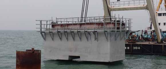
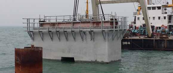
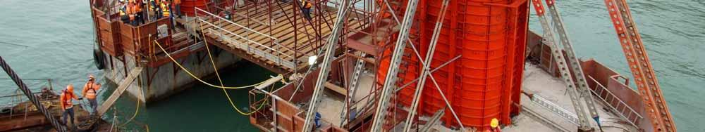
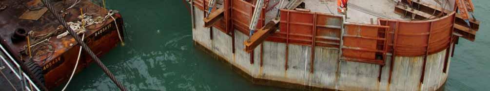
54 Precast Shell for Pile Caps 300t Crane Barge 1 2 Precast Shell Installation 3 HKLR 54 09


55 Precast Shell for Pile Caps 55


56 Precast Shell for Pile Caps 56
57 Precast & In-situ Piers 57


58 In-situ Piers In-situ concrete piers for Typical-span Marine Viaducts In-situ concrete portals for Land Viaducts In-situ concrete twin-blade piers for Long-span Viaducts 58


59 In-situ Piers In-situ concrete piers for Typical-span Marine Viaducts 59


60 Precast Piers Minimize the in-situ concreting in marine condition In-situ concrete for column-stem and upper portions by precast units with U-tendon connections) 60


61 Precast Piers Prestressed Pier at Western Waters 61


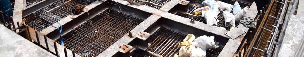
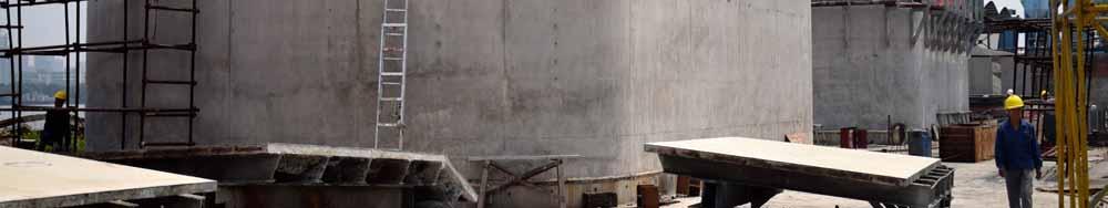
62 Precast Piers Precast Pier Units at Casting Yard 62


63 Precast Piers 63


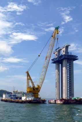
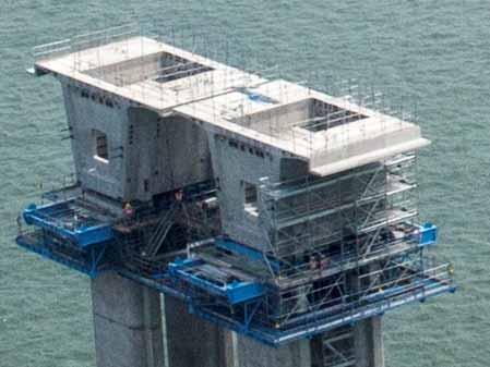
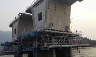
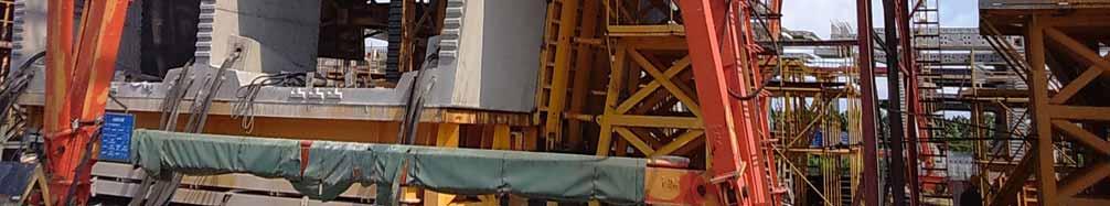
64 Precast Piers Construction of Precast Piers 64
65 Segmental Deck Casting & Erection 65


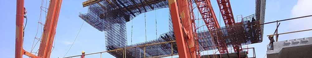
66 Segment Casting Precast Yard Key Technical Information Precast yard size = 250,000 m 2 Total Precast Segments Production = 5,714 nos. Total 7 Production & Storage Lines Total 42 sets of steel prefabricated segment moulds Peak Production = around 330 segments/ month Storage Capacity = 1,300 segments Deck Segment Casting at Precast Yard in Zhongshan

67 Segment Casting Match Casting of Precast Long span Segments

68 Segment Casting Production Line for Typical & Long span Segments 68


69 Segment Casting Segment Storage at Casting Yard 69


70 Segment Casting Delivery to Hong Kong directly by barges 70
 x 24.")


 Boom Length 78m Main")
71 Heavy Lifting Crane Barge Tat Hong m (L) x 24.38m (W) Boom Length 42m Main Hook 234 ton Tat Hong m (L) x 24.38m (W) Boom Length 42m Main Hook 255 ton Tat Hong m (L) x 30.48m (W) Boom Length 78m Main Hook 250 ton


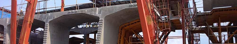
72 Typical Pier Segment Erection Advance Installation of Pier Segment by Crane Barge Maximum segment weight = 165 ton Standard segment length = 2.5m to 2.6m Segment height = 4m to 10m 2 precast segments to form one pier segment 72


73 Hanger Beams Self-Weight = 60 tons per set Total Length = 21m Maximum segment weight = 225 ton Maximum segment length = 4.5 m Maximum segment height = 10.0 m 73


74 LG1 LG2 LF1 Launching Girders and Lifting Frames For Deck Erection LF3
 165m long")
 Unit")


75 Launching Girder (LG1) 165m long 35m wide (Lower Cross Beam) Unit Weight: 1,000 ton 2 Winches - Capacity 130 ton each Maximum segment weight: 120 ton 75
 150 m long")


76 Launching Girder (LG2) 150 m long 33m wide [Transverse Beam] Unit Weight: 700 ton 2 Winches - Capacity 150 tons each Maximum segment weight: 133 ton 76

77 Lifting Frame (LF1) LF1 weight: 280 tons Dimensions: 16 x 9 x 30 m Winch capacity: 240 tons Maximum segment weight: 225 tons Maximum segment length: 4.4 m Maximum segment height: 10.0 m 77

 Used for: Types")


78 Lifting Frame (LF3) LF3 weight: 149 tons (max.) Used for: Types A, C, D & DT Segments Maximum segment weight: 130 to 187 tons Maximum segment height: 4.0 m 78
 40m long, 26m width")

:")

79 Segment Lifter (for P68 & P69) 40m long, 26m width and 17m height Unit Weight: 360T Main Winch (One): Capacity 180T Auxillary Winch (Two): Capacity 10T Maximum segment weight: 170T Travelling Speed: 11m/s (Max)
80 Other Deck Construction Activities 80


81 Other Deck Activities Movement Joints LED Lighting Traffic Aids & Road Marking Sign Gantries Marine Navigation Aids Structural Monitoring System Road Surfacing Roadside Edge Parapet (Precast) Central Median (Precast) Parapet Railing Drainage & Water Mains Systems Landscape Utilities Trough Fascia Panels (Precast) & Cabling


82 HZMB HKLR Optimization of Design & Construction Methodologies to tackle Technical & Programme Challenges Utilization of Precast Concepts & Standardization of Precast Units in Marine Pile Cap Shells, Piers & Decks 82
83 Project Status


84 Aug 2013


85 May 2014


86 Dec 2015


87 Feb 2017
88 Jan 2018


89 Jan 2018
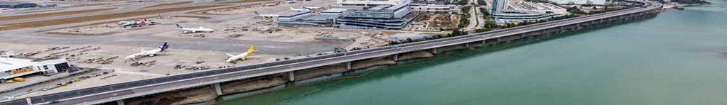

90 Jan 2018
91 Mar 2018
92 Mar 2018
93 Mar 2018


94 Apr 2018
95 Thank You 95
adopted in Hong Kong
 Prefabricated Construction Systems for Building and Civil works adopted in Hong Kong Presented by Raymond W M Wong Division of Building Science & Technology City University of Hong Kong The presentation
Segmental Bridge Technology Established and Evolving. W. Jay Rohleder, Jr, P.E., S.E. Senior Vice President / Project Development FIGG
 1 Segmental Bridge Technology Established and Evolving W. Jay Rohleder, Jr, P.E., S.E. Senior Vice President / Project Development FIGG 2 Segmental Bridge Topics Addressed Definition of concrete segmental
Phase 2 Silver Line Update
 Phase 2 Silver Line Update Committee for Dulles Leslie Pereira, Communications & Outreach Manager Capital Rail Constructors February 16, 2017 Safety Since Notice to Proceed: Manpower Hours: 3,280,898
Moment Resisting Connections for Load Bearing Walls
 PRECAST: MOMENT RESISTING CONNECTIONS Moment Resisting Connections for Load Bearing Walls Manish Khandelwal Sr. Structural Engineer, Building Structures, Sweco India Private Limited Design philosophy for
Dauphin Island Bridge
 Design/Construction Feature Dauphin Island Bridge Presents the major design/construction highlights of the Dauphin Island Bridge a 17,814-ft (5430 m) long prestressed concrete structure located near Mobile,
The $13.2 billion Central Artery/Tunnel Project (CA/
 PART 2 Central Artery/Tunnel Project: Innovative Use of Precast Segmental Technology Paul J. Towell, P.E. Senior Bridge Engineer Bechtel/Parsons Brinckerhoff New York, New York Part 1 of this series of
Overview of Precast ABC Projects in the Pacific Northwest. Chuck Prussack, P.E., Oldcastle Precast, Inc - Spokane
 Overview of Precast ABC Projects in the Pacific Northwest Chuck Prussack, P.E., Oldcastle Precast, Inc - Spokane 1 Techniques Additional prefabrication of units to reduce field timeline Simplify deck installation
BRIDGE TYPE CONCEPT EVALUATION
 SD44/PLATTE-WINNER BRIDGE CORRIDOR STUDY AND ENVIRONMENTAL ASSESSMENT Agreement No. 410583, Work Order PD-19-16 Project Nos. HP5596(19); P0044()290, PCN 05X0 PROJECT MEMORANDUM BRIDGE TYPE CONCEPT EVALUATION
THE TRANSPORTATION ISSUE
 Precast Pavement Perfection // Banking on Precast // California s Precast Express WINTER 2018 THE TRANSPORTATION ISSUE Banking on Precast A variety of precast concrete products will offer the new Bonner
Precast Bridge. in only Eight Days. profile. Minimizing construction-related traffic delays and improving workzone
 Precast Bridge Built in only Eight Days by Peter E. Stamnas and Mark D. Whittemore. New Hampshire Department of Transportation Minimizing construction-related traffic delays and improving workzone safety
ABC and Innovative Bridge Construction for Minnesota Local Roads
 ABC and Innovative Bridge Construction for Minnesota Local Roads May 23, 2013 To box the cha of t unl qua gra ma all g You ma add Tex Chris Werner, PE Senior Bridge Engineer HDR Engineering, Inc. 763-278-5918
FIGG. Accelerated With Bridge Construction. Concrete Segmental. Bridges. William R. (Randy) Cox, P.E. American Segmental Bridge Institute
 Cox, P.E. American Segmental Bridge Institute") Accelerated With Bridge Construction Bridges Concrete Segmental William R. (Randy) Cox, P.E. American Segmental Bridge Institute Outline Introduction Precast Segmental Bridges Balanced Cantilever Span-by-Span
Accelerated With Bridge Construction Bridges Concrete Segmental William R. (Randy) Cox, P.E. American Segmental Bridge Institute Outline Introduction Precast Segmental Bridges Balanced Cantilever Span-by-Span
SUMMARY SHEETS OF BAR COUPLER CONNECTIONS
 APPENDIX A SUMMARY SHEETS OF BAR COUPLER CONNECTIONS NCHRP 12 88 Connection Evaluations Appendix A A 1 APPENDIX A SUMMARY SHEETS OF BAR COUPLER CONNECTIONS NCHRP 12 88 Connection Evaluations Appendix
6/19/2014. Milton Madison Bridge Slide. Project Partners. The Challenge. Aaron L. Stover, PE, SE Michael Baker Jr., Inc.
 Kentucky Society of Professional Engineers May 23 rd, 2014 Lexington KY Milton Madison Bridge Slide Aaron L. Stover, PE, SE Michael Baker Jr., Inc. Project Partners The Challenge Milton, KY Existing Bridge
shawprecastsolutions.com BEBO Arch Systems PRODUCT GUIDE & TECHNICAL REFERENCE MANUAL Providing the right solutions.
 shawprecastsolutions.com BEBO Arch Systems PRODUCT GUIDE & TECHNICAL REFERENCE MANUAL Providing the right solutions. BEBO ARCH SYSTEMS BEBO ARCH units are high quality, low maintenance precast structures
Flanged Dowel Box. Load Transfer System INDUSTRIAL SLAB ON GROUND
 Flanged Dowel Box INDUSTRIAL SLAB ON GROUND Designed for construction joints in Post Tension or large shrinkage specifications Large lateral movement and expansion capacity Eliminates the need to drill
Innovative composite dowel for steel concrete composite bridges. Neil Westmacott, Wolfram Schwarz
 Innovative composite dowel for steel concrete composite bridges Neil Westmacott, Wolfram Schwarz At a glance Cost effective alternative to prestressed bridge girders Introduction New to Australia although
Value Engineering Design Build MODULAR INFRASTRUCTURE
 Value Engineering Design Build MODULAR INFRASTRUCTURE VALUE ENGINEERING When infrastructure projects find themselves in densely populated areas, or occur on a site with poor conditions, the opportunity
James Luebke, PE Structural Development Engineer WisDOT Bureau of Structures
 James Luebke, PE Structural Development Engineer WisDOT Bureau of Structures 1 Highlights WisDOT s ABC Development of PBES Piers Road of Development, Implementation, and Institutionalization Lessons Learned
PRECAST CONCRETE STRUCTURES
 PRECAST CONCRETE STRUCTURES 1. INTRODUCTION The concept of precast (also known as prefabricated ) construction includes those buildings, where the majority of structural components are standardized and
transmit foundation loads
 PILES Long, slender members that transmit foundation loads through soil strata of low bearing capacity or through water to deeper soil or rock strata having a high bearing capacity. End bearing piles End
PRECAST CONCRETE BRIDGE SUBSTRUCTURE COMPONENTS. Presented by: Matthew Youngblood, PE, SE Scott Noyer, PE Janssen & Spaans Engineering
 PRECAST CONCRETE BRIDGE SUBSTRUCTURE COMPONENTS Presented by: Matthew Youngblood, PE, SE Scott Noyer, PE Janssen & Spaans Engineering PRECAST SUBSTRUCTURE COMPONENTS ADVANTAGES SCHEDULE INCREASES CONSTRUCTION
This document downloaded from vulcanhammer.net vulcanhammer.info Chet Aero Marine
 This document downloaded from vulcanhammer.net vulcanhammer.info Chet Aero Marine Don t forget to visit our companion site http://www.vulcanhammer.org Use subject to the terms and conditions of the respective
Composite Sections. Introduction BETON PRATEGANG TKS Session 10: 2015/4/27
 BETON PRATEGANG TKS - 4023 Session 10: Composite Sections Dr.Eng. Achfas Zacoeb, ST., MT. Jurusan Teknik Sipil Fakultas Teknik Universitas Brawijaya Introduction A composite section in context of prestressed
Precast Concrete at Paddington Rail Station, London. By George Jones Member of fib Commission 6
 Precast Concrete at Paddington Rail Station, London By George Jones Member of fib Commission 6 Precast Concrete at Paddington Rail Station Project background. Reasons for using precast concrete and its
Proven precast solutions for every application
 Proven precast solutions for every application Seventy five years of UNDISPUTED LEADERSHIP HP shell roof, bowstring girders and trussed gantry girders for L&T Bengaluru Works Larsen & Toubro is a major
How to Estimate the Cost of a. Precast Concrete Parking Structure
 How to Estimate the Cost of a Precast Concrete Parking Structure 1 TABLE OF CONTENTS 1. INTRODUCTION 2. TYPES AND METHODS OF MEASUREMENT 3. SPECIFIC FACTORS THAT MAY AFFECT TAKE OFF AND PRICING 4. OVERVIEW
Module 10 : Improvement of rock mass responses. Content
 IMPROVEMENT OF ROCK MASS RESPONSES Content 10.1 INTRODUCTION 10.2 ROCK REINFORCEMENT Rock bolts, dowels and anchors 10.3 ROCK BOLTING MECHANICS Suspension theory Beam building theory Keying theory 10.4
MONTH : December 2015 PHOTOGAPH NO: DESCRIPTION : Rebar Installation Work for 1 st Lift of permanent Manhole at MH-G2
 MONTH : December 2015 PHOTOGAPH NO: 000587 DESCRIPTION : Rebar Installation Work for 1 st Lift of permanent Manhole at MH-G2 MONTH : December 2015 PHOTOGRAPH NO: 000588 DESCRIPTION : Concrete Casting for
HOLLOW CORE PRODUCTS GROUNDED IN STRENGTH
 HOLLOW CORE PRODUCTS GROUNDED IN STRENGTH usable space under your garage 8 form - 8 Hollow Core 7' - 11-1/2" 3" min. topping for precast diaphragms 2-3/ 3" MIN. TOPPING FOR PRECAST DIAPHRAGMS 7' - 11-3/4"
Accelerated Bridge Construction (ABC) and the Utah Experience
 and the Utah Experience") Accelerated Bridge Construction (ABC) and the Utah Experience by Kris Peterson, P.E., UDOT Mary Lou Ralls, P.E., Ralls Newman, LLC AASHTO Subcommittee on Construction Annual Meeting Computers and Technology
Accelerated Bridge Construction (ABC) and the Utah Experience by Kris Peterson, P.E., UDOT Mary Lou Ralls, P.E., Ralls Newman, LLC AASHTO Subcommittee on Construction Annual Meeting Computers and Technology
Precast Multistorey Highrise Residential & Commercial Buildings. Buildings & Factories IC
 Precast Multistorey Highrise Residential & Commercial Buildings Buildings & Factories IC LARSEN & TOUBRO LIMITED It s all about Imagineering L&T at a Glance India s largest E&C company, with interests
SUBSTATION SECURITY WALL INSTALLATION MANUAL
 SUBSTATION SECURITY WALL INSTALLATION MANUAL JULY 26, 2016 OLDCASTLE PRECAST, INC. 3000 New McEver Rd, Acworth, Ga 30101 Substation Security Wall Installation Manual This Installation Manual is intended
Digitally Signed 06/02/2015
 Digitally Signed 06/0/05 Digitally Signed 06/0/05 Digitally Signed 06/0/05 FED. ROAD DIST. NO. STATE FED. AID PROJ. NO. SHEET NO. TOTAL SHEETS 6--5 6 ARK. JOB NO. 08057 6 8 075 QUANTITIES 5706 SUMMARY
Diamond Dowel. Load Transfer System INDUSTRIAL SLAB ON GROUND
 Diamond Dowel INDUSTRIAL SLAB ON GROUND Diamond Dowel designed for construction joints Tapered plate design allows for diagonal shrinkage Eliminates the need to drill or process formwork Design ensures
State-of-the-art Report On FULL-DEPTH PRECAST CONCRETE BRIDGE DECK PANELS (SOA )
") State-of-the-art Report On FULL-DEPTH PRECAST CONCRETE BRIDGE DECK PANELS (SOA -01-1911) Vince Campbell Former president of Bayshore Concrete Products Corporation, VA This presentation is developed
State-of-the-art Report On FULL-DEPTH PRECAST CONCRETE BRIDGE DECK PANELS (SOA -01-1911) Vince Campbell Former president of Bayshore Concrete Products Corporation, VA This presentation is developed
Module 5 : Design of Deep Foundations. Lecture 20 : Introduction [ Section 20.1 : Introduction ]
![Module 5 : Design of Deep Foundations. Lecture 20 : Introduction [ Section 20.1 : Introduction ]](/thumbs/82/86090197.jpg "Module 5 : Design of Deep Foundations. Lecture 20 : Introduction [ Section 20.1 : Introduction ]") Lecture 20 : Introduction [ Section 20.1 : Introduction ] Objectives In this section you will learn the following Introduction Lecture 20 : Introduction [ Section 20.1 : Introduction ] INTRODUCTION The
Lecture 20 : Introduction [ Section 20.1 : Introduction ] Objectives In this section you will learn the following Introduction Lecture 20 : Introduction [ Section 20.1 : Introduction ] INTRODUCTION The
IJSRD - International Journal for Scientific Research & Development Vol. 4, Issue 04, 2016 ISSN (online):
:") IJSRD - International Journal for Scientific Research & Development Vol. 4, Issue 04, 2016 ISSN (online): 2321-0613 Comparative Study between Precast and Cast In-Situ Structure Under Combination of Dynamic
IJSRD - International Journal for Scientific Research & Development Vol. 4, Issue 04, 2016 ISSN (online): 2321-0613 Comparative Study between Precast and Cast In-Situ Structure Under Combination of Dynamic
Helical Pier Frequently Asked Questions
 Helical Pier Basics Q: What is a Helical Pier? A: A helical pier or pile is an extendable deep foundation system with helical bearing plates welded to a central steel shaft. Load is transferred from the
Suggested Reinforcement Detailing Practices Based on comments from R&D and ES ESS Committees
 Suggested Reinforcement Detailing Practices Based on comments from R&D and ES ESS Committees General 1. When detailing substructures, it is preferable not to use series bars unless necessary. The first
Erstantie 2, FIN Villähde Tel , Fax
 www.anstar.eu 2 www.anstar.eu 3 CONTENTS Page 1 PRODUCT DESCRIPTION...4 2 MATERIALS AND STRUCTURE...4 2.1 PRODUCT RANGE...4 2.2 MATERIALS...4 2.3 MANUFACTURING...4 2.4 MANUFACTURING TOLERANCES...4 2.5
50.24 Type, Size and Location Plans for Culverts, Bridges and Culvert Bridges
 50.24 Culverts, Bridges and Culvert Bridges Type, Size and Location (T, S & L) Plans shall be required for all Bridges, Culvert Bridges and Culverts of eight-foot (8') clear span or greater as follows:
CE2045-PREFABRICATED STRUCTURES QUESTION BANK
 CE2045-PREFABRICATED STRUCTURES QUESTION BANK UNIT I - INTRODUCTION PART A 1. Define prefabrication 2. What are the types of prefabricates based on i. Plan area ii Based on weight 3. What are the types
General Layout. Eng. Maha Moddather
 General Layout Eng. Maha Moddather mahamoddather@eng.cu.edu.eg Introduction Concrete Beam subjected to Bending Moment around Major Axis M x Compression d Concrete tensile strength is neglected A S Tension
Plate 60 ArmourMate. Joint Edge Protection INDUSTRIAL SLAB ON GROUND. Plate 60 AmourMate. Joint Edge Protection
 Plate 60 AmourMate Plate 60 ArmourMate INDUSTRIAL SLAB ON GROUND Accommodates large concrete shrinkage Facilities thermal movement Prevents spalling on construction joints Extends the life-cycle of the
Construction Tolerances - The following tolerances apply to cast-in-place structures:
 00540.40(b) Construction 00540.40 Tolerances - The following tolerances apply to cast-in-place structures: (a) Foundation Footings: (1) Lateral Alignment: Actual (as cast) location of the center of gravity:
ProConcrete. Gernot Jeromin Product Manager Bentley Systems, Incorporated
 ProConcrete Gernot Jeromin Product Manager ProConcrete 3D CAD Software for Concrete and Reinforcement 2 WWW.BENTLEY.COM What is ProConcrete AutoCAD Application MicroStation V8i version will be available
Precast Concrete Pavement Background Concepts. Project 1517 FHWA, CTR & TxDOT Gary Graham November 15, 2001
 Precast Concrete Pavement Background Concepts Project 1517 FHWA, CTR & TxDOT Gary Graham November 15, 2001 Project Background CTR contracted by FHWA/TxDOT to investigate the feasibility of using precast
PRECAST CONCRETE DESIGN AND ENGINEERING KNOW HOW ALL UNDER ONE ROOF
 PRECAST CONCRETE DESIGN AND ENGINEERING KNOW HOW ALL UNDER ONE ROOF Through inherited experience of its personnel and through its own projects, DNEC have accumulated over 30 years of precast concrete expertise.
PANEL CRIB PIERS AND TOWERS
 CHAPTER 17 PANEL CRIB PIERS AND TOWERS Panel crib piers are made of trusses with panels set horizontally or vertically and are normally braced with transoms, sway bracing, rakers, bracing frames, and tie
Segmental Bridge Construction. Segmental Bridges It s a Construction Technique with Design Implications. Plans Review Group
 Structures g Design Plans Review Group Segmental Bridge Construction Segmental Bridges It s a Construction Technique with Design Implications 2010 FDOT/FTBA Construction Conference February 23-24 Orlando,
APPENDIX C: MAIN RIVER BRIDGE PLANS. The graphics in this appendix depict the Practical Alternatives.
 APPENDIX C: MAIN RIVER BRIDGE PLANS The graphics in this appendix depict the Practical Alternatives. NO. DESCRIPTION BY 4:36:17 PM 10/3/2007 STA.10+843.000 \ PYLON 6.000 5.000 (TYP) PYLON ELEVATION 210.000
A. Extent of structural precast concrete work is shown on drawings and in schedules.
 SECTION 03 41 00 - STRUCTURAL PRECAST CONCRETE PART 1 GENERAL 1.1 RELATED DOCUMENTS A. Drawings and general provisions of Contract, including General and Supplementary Conditions and Division 1 specification
Total precast solution for large stadium projects meet tight schedule
 Tailor Made Concrete Structures Walraven & Stoelhorst (eds) 2008 Taylor & Francis Group, London, ISBN 978-0-415-47535-8 Total precast solution for large stadium projects meet tight schedule T.J. D Arcy
Double Storey HC Precast System Drawing - 3D
 Double Storey HC Precast System Drawing - 3D Superstructure ( Frame & Wall ) : - By HC Precast System Sub- Structure By Other : - Appointed By Client 77 % 23 % INDUSTRIALISED BUILDING SYSTEM ( IBS ) is
Cooke Precast Concrete
 Cooke Precast Concrete ACCESS COVERS History Cooke Precast Concrete Pty. Ltd. commenced business in September 1996, with a staff combining together bringing many decades of knowledge and experience within
Anti-Trust Statement
 Anti-Trust Statement http://www.concrete-pipe.org/ A joint effort of the Texas Concrete Pipe Association and the Texas Department of Transportation What brought this about? The TxDOT organization consists
The DFI Institute is organized to serve as a primary means through which members of the Institute may participate in improvement of the planning,
 The DFI Institute is organized to serve as a primary means through which members of the Institute may participate in improvement of the planning, design and construction aspects of deep foundations and
Digital Data. Its use in geotechnical design & execution. Remedy Geotechnics Ltd. Dr Derek Egan Director.
 Digital Data Its use in geotechnical design & execution Dr Derek Egan Director Remedy Geotechnics Ltd www.remedygeotechnics.com Digital Data - Use in geotechnical design & execution Introduction Aims of
TECHNICAL MANUAL. TERADOWEL and ULTRADOWEL. Reliable Dowel System for Floor Joints
 TECHNICAL MANUAL TERADOWEL and ULTRADOWEL Reliable Dowel System for Floor Joints Version: PEIKKO GROUP 11/2018 TERADOWEL and ULTRADOWEL Reliable Dowel System for Floor Joints Dowels manufactured from high
SPECIFICATIONS FOR THE MANUFACTURE AND DESIGN OF PRECAST THREE SIDED ARCH STRUCTURES, WINGWALLS AND HEADWALLS
 SPECIFICATIONS FOR THE MANUFACTURE AND DESIGN OF PRECAST THREE SIDED ARCH STRUCTURES, WINGWALLS AND HEADWALLS 1. DESCRIPTION THESE SPECIFICATIONS ARE FOR A PRECAST THREE SIDED ARCH STRUCTURE, HEADWALLS
Unit 8 Precast Concrete
 Part ⅠIllustrated Words and Concepts Figure 8-1 Precast Slabs on a Frame of Precast Columns Figure 8-2 Hollow-core Slabs Supported on Precast Concrete Wall Panels Part Ⅱ Passages Passage A Precast Concrete
TECHNICAL NOTE SEGMENTAL BRIDGE WIZARD. Introduction. Segmental Bridge Span Assembly
 COMPUTERS AND STRUCTURES, INC., MARCH 2015 TECHNICAL NOTE SEGMENTAL BRIDGE WIZARD Introduction This document describes the use of the segmental bridge wizard, including functionality, options, and terminology.
Engineering and Construction Services Division Construction Drawings for Sewers and Watermains. T No. Revision T No. Revision Remarks All T drawings
 Engineering and Construction Services Division Construction Drawings for Sewers and Watermains Revision No. 8 April All T drawings New title block for each drawing is now standardized. Revision numbers
DEEP FOUNDATIONS PILES
 DEEP FOUNDATIONS PILES Pile foundation used to support structure when poor quality soil bearing capacity failure excessive settlement piles END BEARING PILES SKIN FRICTION PILES End bearing pile rests
MANuFACturers industry QuALity statement.
 MANuFACturers industry QuALity statement Precast New Zealand Inc. (PCNZ) was established in 1999 and is a national industry association of precast concrete manufacturers representing over 90% of the off
Utility Structures. Utility vaults, trenches, transformer pads Electrical Pole Bases and switching cubicles
 Utility Structures Utility vaults, trenches, transformer pads Electrical Pole Bases and switching cubicles PRODUCT GUIDE & TECHNICAL REFERENCE MANUAL Providing the right solutions. UTILITY STRUCTURES Perfect
PD 3 Dowel Cradle. Load Transfer System Industrial Slab on Ground
 PD 3 Dowel Cradle Industrial Slab on Ground Provides the flattest joints Assists in reducing long term maintenance costs Extends the life-cycle of the floor and the asset Engineered to meet Super Flat
STRUCTURAL ATTACHMENTS
 Brace Structural Attachment Selection Procedure ) Determine structure to be attached to from the following: A) Concrete B) Wood Beam C) Structural Steel 2) Reference structure connection type from Appendix
ADDENDUM NO. 2. Furnace Bridge - Installation. Essex County, NY. July 29, 2015
 ADDENDUM NO. 2 Furnace Bridge - Installation Essex County, NY July 29, 2015 TO ALL HOLDERS OF BIDDING DOCUMENTS: This Addendum, issued to bid document holders of record, indicates clarifications to the
SOFRASAR TUNNEL PRODUCTS CONNECTING ALL COMPONENTS
 www.optimas.com SOFRASAR TUNNEL PRODUCTS CONNECTING ALL COMPONENTS CONTENTS DOWEL SYSTEM SOF-FIX ANIX 110 PG. 06 DOWEL SYSTEMS 04 BOLTING SYSTEMS 08 GROUT LIFT SOCKETS 11 CENTERING DOWELS AND SHEAR DOWELS
INDEX. Initial SOL Approval. 1. Evergreen Retaining Wall System (Deleted) 3. Sound Barrier Walls (Deleted) Standard Details
 3. Sound Barrier Walls (Deleted) Standard Details") INDEX Product 1. Evergreen Retaining Wall System (Deleted) 2. Precast Barlok Parapet 431-92-05 Drawing No. PADOT # 92-051-PE 3. Sound Barrier Walls (Deleted) Standard Details 4. Sound Zero Panel-Noise
INDEX Product 1. Evergreen Retaining Wall System (Deleted) 2. Precast Barlok Parapet 431-92-05 Drawing No. PADOT # 92-051-PE 3. Sound Barrier Walls (Deleted) Standard Details 4. Sound Zero Panel-Noise
MAHALAKSHMI ENGINEERING COLLEGE TIRUCHIRAPPALLI DEPARTMENT OF CIVIL ENGINEERING QUESTION BANK UNIT I - INTRODUCTION
 MAHALAKSHMI ENGINEERING COLLEGE TIRUCHIRAPPALLI- 621 213 DEPARTMENT OF CIVIL ENGINEERING QUESTION BANK UNIT I - INTRODUCTION Need for prefabrication Principles Materials Modular coordination Standardization
Delivering Reliability. Services. Strength You Can Count On. oldcastleprecast.com/services
 Delivering Reliability A Strength You Can Count On SERVICES TENANT IMPROVEMENTS Above And Below Ground Solutions Strength You Can Count On Oldcastle Precast is well trained and knowledgeable in all aspects
1. Enumerate the most commonly used engineering materials and state some important properties and their engineering applications.
 Code No: R05310305 Set No. 1 III B.Tech I Semester Regular Examinations, November 2008 DESIGN OF MACHINE MEMBERS-I ( Common to Mechanical Engineering and Production Engineering) Time: 3 hours Max Marks:
Cooke Precast Concrete
 Cooke Precast Concrete History Cooke Precast Concrete Pty. Ltd. commenced business in September 1996, with a staff combining together bringing many decades of knowledge and experience within the precast
SEA SELF DRILLING, THREADED, HOLLOW BAR / GROUT-ABLE SOIL NAILS / ANCHORS
 SEA SELF DRILLING, THREADED, HOLLOW BAR / GROUT-ABLE SOIL NAILS / ANCHORS THE SEA SYSTEM SEA hollow T threaded bar Rock Anchors / Soil Nails provide the ultimate solution for securing unstable embankments
11/15/2010. Construction. Accelerated Bridge Construction (ABC) Definition. Systems (PBES) Definition
 Definition. Systems (PBES) Definition") Successes in Accelerated Bridge Construction Mary Lou Ralls, P.E. Principal Ralls Newman, LLC (formerly Texas State Bridge Engineer) 1 Accelerated Bridge Construction (ABC) Definition Structural & geotechnical
Successes in Accelerated Bridge Construction Mary Lou Ralls, P.E. Principal Ralls Newman, LLC (formerly Texas State Bridge Engineer) 1 Accelerated Bridge Construction (ABC) Definition Structural & geotechnical
PRACTICE NOTE NO: 13 Version 1 Amended March 2001 Page 1 of 6 PRECAST CONCRETE ELEMENT DESIGN RESPONSIBILITIES AND CONTRACTUAL ARRANGEMENTS
 PRACTICE NOTE NO: 13 Version 1 Amended March 2001 Page 1 of 6 Scope This Practice Note is intended to identify responsibilities and contractual arrangements for precast elements used in buildings. Such
WEB-BASED QUALITY CONTROL OF PRECAST CONCRETE
 WEB-BASED QUALITY CONTROL OF PRECAST CONCRETE G. Arslan, O. Arıöz, M. Tuncan, S. Kıvrak Civil Engineering Department, Anadolu University, Eskisehir, Turkey E-mail: gokhana@anadolu.edu.tr ABSTRACT: Precast
EXPERIENCES OF HIGH STRAIN DYNAMICS PILE TESTING (HSDPT) IN ACCORDANCE WITH EC7 IN SWEDEN
 IN ACCORDANCE WITH EC7 IN SWEDEN") EXPERIENCES OF HIGH STRAIN DYNAMICS PILE TESTING (HSDPT) IN ACCORDANCE WITH EC7 IN SWEDEN Mattias Grävare 1, Ingemar Hermansson 1, Thomas Bjerendal 1, Carl-John Grävare 1 1 Pålanalys i Göteborg AB Sweden,
EXPERIENCES OF HIGH STRAIN DYNAMICS PILE TESTING (HSDPT) IN ACCORDANCE WITH EC7 IN SWEDEN Mattias Grävare 1, Ingemar Hermansson 1, Thomas Bjerendal 1, Carl-John Grävare 1 1 Pålanalys i Göteborg AB Sweden,
Fast Track Precast Concrete Pavement Rehabilitation Pilot Project
 Fast Track Precast Concrete Pavement Rehabilitation Pilot Project Susanne Chan, M.A.Sc, P.Eng. Pavement Design Engineer, Ministry of Transportation Ontario Warren Lee, M.A.Sc, P.Eng. Pavement Design Engineer,
To: New York State Department of Transportation ENGINEERING INSTRUCTION. Approved:
 To: New York State Department of Transportation ENGINEERING INSTRUCTION Title: PRECAST CONCRETE PAVEMENT SLAB SYSTEMS STANDARD SPECIFICATION Distribution: Manufacturers (18) Local Govt. (31) Agencies (32)
Architectural Precast Concrete Presentation May 2009
 Presented by Nomenclature Architectural Precast Concrete Martin Newland B.E. M.I.E. Aust CP Eng SA Precast Pty. Ltd. 72 Days Road CROYDON PARK SA 5008 Ferrule Grout tube PHONE: 8346 1771 FAX: 8340 1645
JVI Vector Connector
 The JVI Vector Connector User Guidelines 1 of 11 INTRODUCTION JVI designed the Vector Connector for use as shear and alignment connections between precast concrete elements such as double-tee flanges,
Stellenbosch University South Africa CONSTRUCTION ENGINEERING & MANAGEMENT CHAIR. Jan Wium
 Stellenbosch University South Africa CONSTRUCTION ENGINEERING & MANAGEMENT CHAIR Jan Wium Pretoria Cape Town SOUTH AFRICA Johannesburg Stellenbosch 1 Academic offering (CEM) Stellenbosch University/Engineering
CIVIL CONSTRUCTION PRODUCT CATALOG VOL. I
 CIVIL CONSTRUCTION PRODUCT CATALOG VOL. I Table of Contents Section Description A page CHANCE Helical Round Corner Square Shaft Products Introduction to Round and Square Shaft 3 Square Shaft (SS) Product
PCI Update on Transportation Activities and elearning Modules for AASHTO Technical Committee T-4 AASHTO SCOBS --- Spokane Washington
 PCI Update on Transportation Activities and elearning Modules for AASHTO Technical Committee T-4 AASHTO SCOBS --- Spokane Washington June 2017 William N. Nickas, P.E. Managing Director, Transportation
RAPID CONSTRUCTION-INOVATIVE APPROCH OF PREFABRICATED CONSTRUCTION
 RAPID CONSTRUCTION-INOVATIVE APPROCH OF PREFABRICATED CONSTRUCTION Krushil K. Ponkiya 1, Dhyey K. Shah 2, Rushabh A. Shah 3 PG. Student, SNPIT & RC, Umrakh, Gujarat, India 1 PG. Student SNPIT & RC, Umrakh,
CAT-350 Product Manual
 CAT-350 Product Manual Release 01/17 www.ingalcivil.co.nz CAT-350 NZ Assembly Manual Ingal Civil Products NZ 40 Tironui Road, Auckland 2112 www.ingalcivil.co.nz Important: These instructions are for standard
WELCOME Visit To IBS Factory IBS Superstructure In Malaysia 3 in 1
 WELCOME Visit To IBS Factory IBS Superstructure In Malaysia 3 in 1-2017 - Industrialised Building System ( IBS ) is a system not a machine or component. Open System and Proprietary System is a Technology.
LETTING : CALL : 029 COUNTIES : GOODHUE
 PAGE : -1 NUMBER OF DAYS: 80 BRIDGE COUNT : 2 CONTRACT DESCRIPTION : GRADING, SURFACING, LIGHTING AND BRIDGE NO. 25024. CONTRACT LOCATION: LOCATED ON T.H. 61 FROM 30' NORTH OF NORTH LAKESHORE DRIVE TO
PRECAST TO LAST. S C Lam, K C Chung and S W Sham Hong Kong Housing Department
 PRECAST TO LAST S C Lam, K C Chung and S W Sham Hong Kong Housing Department Abstract: The Hong Kong Housing Authority (HA) pioneered the precast concrete construction in high-rise residential buildings
Edgerail Aluminum Bridge Railing System Specification & Installation Instructions
 Edgerail System Specification & Installation Instructions Hill & Smith, Inc 1000 Buckeye Park Road Columbus, Ohio 43207 Tel: 614-340-6294 Fax: 614-340-6296 www.hillandsmith.com Section A System Specification
HEXAGONAL DOUBBLE TWISTED GABION & ROCK FALL MATRESSES
 Menufatchurar of HEXAGONAL DOUBBLE TWISTED GABION & ROCK FALL MATRESSES As per IS 16014 (2012): Mechanically woven, double -twisted, hexagonal Wire Mesh Gabions, Revet Mattresses and Rock fallnetting(
B. Installation Instructions. Provide installation instructions, including any special equipment, to address the following.
 SAMPLING AND TESTING. The Sampling and Testing requirements contained in -03 shall apply. MARKING. The Marking requirements contained in -03 shall apply. FINAL PRODUCTION INSPECTION. The Final Production
State of the Art Precast, Prestressed Concrete Bridges and Industry Innovations
 State of the Art Precast, Prestressed Concrete Bridges and Industry Innovations William N. Nickas, P.E. Managing Director, Transportation Services Precast/Prestressed Concrete Institute Chicago, IL. LEARNING
Project Reference Catalogue
 Reference Catalogue www.wiecon.com.tw Reference Catalogue. West Coast Freeway No. 61, Fangli to Da-an, Taichung Coastal Area, Taiwan. Precast Segmental Bridges. : Ta-Chen Construction & Engineering Coorporation.
Custom corner pile by Skyline Steel. Backfill with limestone quarry compacted in 6-8" layers to min. 95% dry density. 12" thk RC Footing 61'-9"
 ' ustom corner pile by Skyline Steel ' SKZ sheet piles by SKYLINL, installed as per manufacturers recommendations ' ' " ' " ' Mx0 6 steel 6' 9'0" 9' ' ' New Ø precast xisting bridge to be xisting pile
Installation Instructions
 Installation Instructions SRT-350 8 POST Guardrail End Treatment Revised July 2005 TRINITY HIGHWAY SAFETY PRODUCTS, INC. BUILDING TOMORROW S HIGHWAY SAFETY SOLUTIONS TODAY 2 SRT TM 8-POST SYSTEM FOR SPECIFIC