ZW3D CAD Fundamentals Training Guide
|
|
|
- Ronald Pierce
- 5 years ago
- Views:
Transcription
1 ZW3D CAD Fundamentals Training Guide
2 Copyright and Trademarks Copyright 2017 ZWCAD Software Co., Ltd. All rights reserved. 32/F Pearl River Tower, No.15 Zhujiang West Road, Tianhe District, Guangzhou , P.R.China (8620) ZW3D V2017 CAD Fundamentals Training Guide This documentation may be reproduced provided it complies with the terms presented on the LICENSE AGREEMENT supplied. ZWCAD Software Co., Ltd and the program authors have no liability to the purchaser or any other entity, with respect to any liability, loss, or damage caused, directly or indirectly by this software and training materials, including but not limited to, any interruptions of service, loss of business, anticipatory profits, or consequential damages resulting from the use of or operation of this software. Updates may be made to this documentation and incorporated into later editions. ZW3D is a registering trademark of ZWCAD Software Co., Ltd. The ZW3D logo is a registering trademark of ZWCAD Software Co., Ltd. ZWCAD, ZWSOFT, the ZWCAD logo, and the ZWSOFT logo are all trademarks of ZWCAD Software Co., Ltd. Printed in the P. R. China. Fundamentals 1
3 Forward The full version of the ZW3D documentation is available by selecting Help Browser from the ZW3D Help Menu. Go to the "Program Folder\doc" directory on the ZW3D program directory and open the file "ZW3D.chm". This CAD Fundamentals Training Guide is available as a printed manual and in PDF format. To view or print the PDF version, install the Adobe Acrobat Reader and open the corresponding files in the "Program Folder\PDF" folder in the program directory. Refer to the HELP Manual for information relating to specific tasks. NOTES: 1. For best results, view and print the PDF version of the documentation using the Adobe Acrobat Reader. 2. Since the CAD Fundamentals Training Guide is only a portion of the complete documentation, it is highly recommended that you utilize the HELP Manual. You will find additional topics, more information on command options, input options, additional command notes, and cross-links to related tasks and topics. 3. It should be noted that the HELP Manual will always be more up-to-date than any printed or PDF material. If you find any discrepancies between the two, always refer to the HELP Manual. 4. While you are working with ZW3D, simply press F1 to view the documentation about the command you select. To help you customize your CAD/CAM requirements, please contact our Customer Support department on our website or call at (8620) ext 565. You can also contact your local sales representative or application engineer to discuss your requirements. Thanks for being our customer! Team ZW3D Fundamentals 2
4 Table Day Support Files and System Requirements... 5 Chapter The ZW3D User Interface... 8 Lesson Managing ZW3D data at the Object Level Chapter Understanding the Right Click Menu Lesson Sketching with the Right Click Menu Chapter Understanding Sketch Tab Lesson Working with ZW3D Sketching Tools Lesson Applying 2D Constraints Lesson 4a Working with ZW3D Constraints Basics Lesson 4b Working with ZW3D Constraints Advanced Chapter Basic Solids Design and Editing with ZW3D Lesson Basic Solid Modeling & Editing Techniques Day Chapter Datum Planes and Reference Geometry Chapter Creating Holes, Fillets and Chamfers Lesson Creating Placed Features Fundamentals 3
5 Chapter Working with Multiple Components Lesson Working with Multiple Components Chapter Creating Face Draft and Copying Features Lesson Creating Face Draft Chapter Editing and Managing ZW3D Objects Chapter Customizing ZW3D CAD Templates Lesson Customizing ZW3D CAD Templates Appendix A Best practice settings for the ZW3D Configuration Form Appendix B ZW3D PDM Fundamentals 4
6 Day 1 Support Files and System Requirements Fundamentals 5
7 The ZW3D download file The ZW3D download file contains all of the necessary support files that will be used throughout this training class. The ZW3D support files should automatically copy into the training folder located in your user directory. For example you should see the training files in C:\Program Files\ Program Folder \training. This is your own personal copy of all training files. Maintain the copy in your Program Files directory as a backup of your original unmodified training data for future use. See figure below for reference. If you browse the Program Files\ Program Folder location you will also find a PDF directory that contains the electronic copy of basic training and installation manuals. Fundamentals 6
8 System Requirements ZWCAD Software Co., Ltd. recommends the following configuration for operation of ZW3D. Recommended configuration Intel Pentium IV(2GHz or up), Intel Xeon, Intel Core or equivalent AMD processor 2GB RAM and up 8GB Hard Disk space for installation and up 2GB swap space and up 3 Button Mouse with scroll wheel Microsoft DirectX 9 -capable graphics card and up or OpenGL-capable graphics card , , bit Color Video resolution Minimum configuration Intel Pentium IV(2GHz or up), Intel Xeon, Intel Core or equivalent AMD processor 1GB RAM 1GB swap space 1GB Hard Disk space for installation 3 button mouse Microsoft DirectX 9 -capable graphics card and up or OpenGL-capable graphics card 1024 x bit Color Video Resolution Operating Systems Supported Microsoft Windows XP SP3(32 bit) Microsoft Windows 2003 Server(32 bit) Microsoft Windows 2008 Server(32 bit) Microsoft Windows Vista(32 bit or 64 bit) Microsoft Windows 7(32 bit or 64 bit) Microsoft Windows 8.1(32 bit or 64 bit) Microsoft Windows 10(32 bit or 64 bit) Required for licensing Ethernet card or Hardware key Required for Floating License Installation of TCP/IP Network Protocol Recommended for training and support Speakers or head phones Space Ball devices are supported Fundamentals 7
9 Chapter 1 The ZW3D User Interface Fundamentals 8
10 Starting a Basic ZW3D Session Use the NEW or OPEN commands to begin creating a new ZW3D project file. ZW3D Project files are given the file extension Z3. A project file can contain multiple ZW3D objects such as Parts, Assemblies, Drawings, 2D Sketches, Equation Sets or CAM Process Plans. See the ZW3D Objects form on the following page for reference. Once you have launched your ZW3D Software, use the OPEN form shown below to specify the name of a new or existing project file you would like to work on. ZW3D will create the project file if it does not exist or if it is not in the ZW3D search path. The search path can be adjusted to meet your requirements. See the HELP Manual for information on the search path. OPEN a File Use the Create a New File form to specify what type of ZW3D object you are going to create. You can choose from a template displayed at the lower left corner when creating new ZW3D objects. Templates are standard ZW3D objects contained in the files Templates_MM.Z3" and Templates_IN.Z3 These files are typical ZW3D CAD/CAM files with root level objects containing your company s design and drafting standards, or manufacturing strategies. Microsoft WORD uses dot files as templates. We will talk about adjusting this template file to meet your requirements later in this manual. The unique name and description could be also added in the form. When using the Create a file command inside of ZW3D, after exiting to the root level, the ZW3D Objects manager will be displayed. Several commands such as Edit a object and delete objects are displayed on the right-click menu. Use this form to manger a variety of objects or edit existing objects. Fundamentals 9
11 Basic Work Flow The ZW3D data hierarchy allows root objects such as parts, assemblies, sketches, drawing packets, and CAM plans associated with a design to be stored in a single manageable ZW3D object file. When you are running ZW3D it is referred to as the active session. The active session is a temporary work area into which portions of ZW3D files are loaded as needed during a design or revision. The active session stores only the modified data. The session concept allows large complex parts and assemblies to be worked on as efficiently as the simplest part. You can view and manipulate the entire design while only the objects and entities being edited are retrieved thus requiring less system resources. The figure below illustrates the basic workflow during the active session. ZW3D Temporary Undo/Redo History File Edits Only Active Session File 1.Z3 File 2.Z3 Edited Objects Edited Objects Permanent Archive Saved Files File 1.Z3 File 2.Z3 All Objects All Objects Basic Workflow Fundamentals 10
12 The Active Session When you are running ZW3D it is referred to as the Active Session. When you create a new file it resides in the active session and contains the initial root objects that you create. When you save a file that is new and has not been saved yet, the File Browser is displayed and defaults to the "File Save" directory defined on the Files tab of the ZW3D Configuration Form or the last directory specified by this command or the Save File As command. If you save all files and one of the files is new, it is saved from the active session to the "File Save" directory mentioned above. When you open a file, the active session only retrieves the root objects and sub-objects needed. Also, display information is loaded on-demand. Display information that lies outside the initial view window, that is blanked, or that isn't needed for the active display mode (e.g., facets for shading) is not loaded. This is all part of the ZW3D efficient object manager. A file opened during the active session does not represent the entire file - only what you have edited. When you save a file that was opened, the original file is updated and the session is cleared of the file. You can think of the active session as an efficient work area where multiple files can be created, opened and then saved as needed. When you save a file or save all files that are new to the active session, they are copied to a permanent (archive) directory that you specify. At that time they become archived files. When you open an archived file, only the root objects (and sub-objects) that you edit are retrieved. These are referred to as file edits. When you save the session it only contains the file edits. It does not contain the complete archived file. When you save a file or save all files (that were archived files) the archived files are updated with the new file edits. Once this occurs, the file edits are cleared from the active session. File Object Part / Assembly Drawing Packet Drawing Sheet Sketch CAM Plan Sketch Drawing Sheet Note: It is important to remember that the UNDO and REDO history is maintained only during each session and that every time a file in the session is SAVED, the UNDO and REDO history is reset. Fundamentals 11
13 Session Management The use of session management starts in the configuration file. Click on Configuration > General tab. See the Session part. By default all the options in this section are disabled. The first option, Enable session management is the key. This turns on or off the use of session management. Session management can be thought of as having two definitions. 1. The first is simply a quick way of saving data during your work day. 2. The second is more sophisticated. I like to think of it as What if Analysis. 3. As described above, the active session only retrieves the root objects and sub-objects as needed. When you activate a previously archived part and start making changes, only those changes are stored in the session. So it is logical to conclude that when you save the session using File > Manage Session >Backup Session, it will be fast. After using Backup session you could exit out of ZW3D without Saving the File and the next time you enter ZW3D you will be returned to the exact spot you left your part. Click on the button of the graph to show hidden menu items. 4. What if Analysis, This is the real power of Session Management. You start with a part that has already been archived or saved. Engineering comes in and says, I would like to try two different scenarios. We will call them, Test-A and Test-B. Pick Open Session and enter Test-A Open the File/part Make the changes. Pick Backup session Pick Open Session and enter Test-B Open the File/part again. Make the changes. Pick Backup Session. Now engineering has the choice of going with Test-A or Test-B. Pick Open Session and pick Test-A then Test-B to switch between the two. When a decision has been made Pick File > Save The changes made in that session will now be saved to the archive file. Fundamentals 12
14 There are two ways to clean up the out-of-date sessions. 1. Click File > Close All then File > Manage session > delete session 2. Go to your User directory and delete the.session directory. The last feature concerning sessions we will cover here is the Emergency session backup.(see the Session part in Configuration> General tab) If you have selected this option in the configuration, there is a good chance that your session will be backed up in the unfortunate circumstance of a crash. This session is written to a separate location from the standard Backup session(see File > Manage Session > Open Session). Session was our active session and EmergencyBackup001 was saved when ZW3D crashed. This is done in case the crash is not able to create a clean save. We didn t want to overwrite your last legitimate backup. Open ZW3D and you will be returned to where you last did a Backup session command. Open the EmergencyBackup and compare the results to your previous backup. I suggest that you do a regen of the history to make sure that the file is not corrupt. ZW3D puts the backup in a separate "emergency" directory so the user can check it out and use it if desired -- otherwise, he still has his last good backup. The emergency session backup is only triggered by certain signals that we are able to intercept. Killing the process or pulling the plug doesn't get through to our signal handler. Key Mouse terms used in this training manual In an attempt to keep things simple and follow a standard format in this training manual we have implemented the use of a few abbreviations. As you go through the exercises that were designed for you to practice you will see abbreviations as described below. <Left-click> means to press the left mouse button. (LMB) <Middle-click> means to press the middle mouse button. (MMB) <Right-click> means to press the right mouse button. (RMB) <Right-click> Draw means to press the right mouse button and pick the Draw command. A variety of commands will be shown to you throughout this training manual to help locate commands. We will use the right click menus as much as possible since they give quick access to the available commands or options for the task at hand. <Shift-click> means to hold down the <Shift> key and press the left mouse button. This will chain pick connected entities. <Ctrl-click> means to hold the <Ctrl> key and press the left mouse button. This will unselect a highlighted entity. Fundamentals 13

15 Other conventions used in the training manuals Edit>Scale This means select the Edit pulldown menu and select the Scale command. The Object Editor The Object Editor provides a quick and easy way to perform many frequently used editing commands. Simply move the cursor over an object such as a curve, text, or feature. That object will highlight. Right-click the mouse to display a set of editing commands tailored to that specific object type. You can also double-left-click on an object such as a sketch to activate it for editing or a curve to activate the curve editor. These are quick response requests that require no additional selections or input. The table below describes the Object Editor functionality of each mouse button. Mouse Button Functionality for Object Editing Single click - picks entities and adds them to an active list. Left Middle Right Double click - selects an entity and automatically invokes a default command to process the entity. Single click - Accepts the active list (from the single-left-click) and displays a menu of options for processing the list. Single click (With an entity highlighted) - picks the entity and displays a menu of options for processing it. Single click (With no entity highlighted) - displays a default menu for inserting/creating objects and various other options. Fundamentals 14

16 Place your cursor over an object and it will highlight. Press the <Right-click> to display an object oriented menu of options for processing the highlighted object. With no entity highlighted, pressing the <Right-click> will display a menu of ZW3D commands. Pick multiple ZW3D objects with the LMB to highlight them. Press the <Right-click> to display a menu of options for processing all of the highlighted objects. Undo / Redo If you make a mistake or change your mind, ZW3D allows you to undo (Ctrl+Z) the last executed command. If you change your mind about undoing a command you can redo (Ctrl+Y) it. You can move back and forward through the undo/redo steps of your design. Only a few viewing related functions are not logged as an undo redo step. Ctrl + Z is the keyboard macro for Undo. Ctrl + Y is the keyboard macro for Redo. Keyboard macros are displayed in Tool tips. Control of the amount of memory allocated to storing the Undo and REDO data per ZW3D session is defined in the configuration. Go to the Utilities pull down menu. Pick the Configuration menu. Then Pick the General tab and make your adjustments. The ZW3D Data Manager The ZW3D Data Manager is a tool that you can use to control many aspects of your part, lights, drawing or CAM plan. It contains the History Manager, Assembly Manager, Layer Manager, View Manager, the Input Manager and Visual Manager, each on Fundamentals 15
17 separate tabs. Not all of the managers will be available at any given time. Refer to the HELP Manual for each of the managers to understand how they operate. Refer to the HELP Manual Also refer to the HELP Manual for the following basic functionality. Hints - Show Hints Part Level - About the Part Level Sketch Level - About the Sketch Level Drawing Packet Level - About the Drawing Packet Level Drawing Sheet Level - About the Drawing Sheet Level ZW3D - Configuration Form Function Keys - About Tool Bars Utility - Tool Bars and Control Keys Other Keys Mouse - for Accepting Default Values File Level Blank Entities (Blank, Unblank, Swap) Fundamentals 16
18 Lesson 1 Managing ZW3D data at the Object Level Fundamentals 17
19 Launch ZW3D and OPEN the file Fundamentals.Z3. directory See the \ Program Folder \training You will see several ZW3D objects in this file at the lower right corner of the form. You may doubleclick on a object to open it or click the Open button to reach to object browser.we will be working with many of these objects throughout this training course. At the ZW3D Object level we can perform a variety of operations in the currently active ZW3D file. We can perform file maintenance, Copy objects, Delete Objects, Move objects, Rename objects and Preview objects. We can even copy objects to other ZW3D files. Let s practice some of these operations. Click the Open button to reach to object browser 1. Pick the Part/Assembly icon from the ZW3D root. A form will appear. We can use this form to create a new ZW3D object file and activate it for editing. A ZW3D file can contain any number of root objects objects (e.g., parts, assemblies, drawings, sketches, CAM process plans, etc.) related to a design. The Part/Assembly icon should be active. Notice the Template window displays [Default], PartTemplate(MM) or PartTemplate(IN). Templates are a method for building your design, drafting and manufacturing standards into ZW3D. We will cover customizing templates to meet all of your corporate, department or personal requirements later in this manual. The Name defaults to Part001. Pick OK to accept the default part object name. 2. ZW3D created a Part/Assembly object named Part001 as indicated in the title bar 3. We won t be creating any geometry in these objects yet. Exit Part menu when you are finished. This command is also conveniently located on the RMB 4. Notice Part001 has been added to the current ZW3D files list of objects. 5. Pick the Sketch icon from the ZW3D root. 6. Notice the Templates window changes. We currently have no sketch templates defined per our standards. 7. Pick OK to accept the default sketch name. 8. ZW3D creates a Sketch object named Sketch001 as indicated in the title bar. Fundamentals 18
20 The XY icon in the middle of the screen indicates 0,0. We also create a point and an anchor constraint at this location for your convenience. 9. Exit Sketch when you are finished. 10. Notice Sketch001 has been added to the current ZW3D files list of objects. 11. So far we have added 2 blank objects to our ZW3D file. Let s delete them now since we don t really need them. In the ZW3D Objects form, <Right-click> over the Part001 object The menu displayed offers a variety of functions that can be performed on this object. Pick DELETE. <Right-click> over the Sketch001 object and pick DELETE. 12. Let s review the Preview section in the top of the ZW3D Objects Manager form. Select the Graphics option from Preview pull-down list. <Left-click> over a couple of the Part objects in this form. A graphic preview of each object will appear in the upper left corner of the screen. The preview can be displayed in wireframe or shaded mode. To change the display mode of the preview use the keyboard macro <CTRL-F> to toggle the display. 13. Select the Attributes option from Preview pull-down list. <Left- Click> over one or two of the part objects to display the Part attributes form. These forms contain Bill of Material information, parametric relations for deriving families of parts and user defined attribute information. This information is also used to semi-automatically fill in the title block on a drawing. (See Edit > Regen Text in the sheet) Fundamentals 19
21 14. Dismiss the Attributes form if it is still displayed on your screen. 15. Set the Preview to OFF. Next we will review the Copy option. 16. <Right-click> over the Blow Mold Completed object and choose Copy from the shortcut menu. This copies the object to the clipboard. 17. <Right-click> and choose Paste from the shortcut menu. A new object named Blow Mold Completed_1 is created. You will see the additional copy appear in the ZW3D Objects form. 18. You can also open another file and pick Paste to copy the Blow Mold Completed part object. The two parts are not linked in any way but the history is maintained. 19. Let s talk about Rename. This option is found on the shortcut menu when you <Rightclick> an object. Rename allows us to change the name of an existing ZW3D object. Try renaming our new copied part. 20. Let s edit Blow Mold Completed. To do this double click on its name or <Right-click> and choose the Edit. 21. Let s review some of the display manipulation commands. Use the keyboard macros or pick the icon as shown in the following steps. + Set Display to Shade. + Zoom Window. + Zoom All. + Top View. + Front View. + Left View. + Right View. Fundamentals 20
22 22. These next few steps will help us understand how to use the Dynamic Rotate, Pan and Zoom commands in ZW3D. < Middle -click>and drag will allow you to PAN the display. Try this. < Rolling the mouse > will allow you to ZOOM the display. Try this. <Right-click>and drag will allow you to ROTATE the display. Try this. Dynamic rotate rotates about the view origin. you can simply RMB - Drag to dynamically rotate, LMB - Drag to Pan. 23. Use the key to rotate your model. While the F3 key is pressed, Dynamic Rotate will be constrained about the Z-Axis. Pan and Zoom are not affected. Try this. 24. Use the key to rotate your model. While the F4 key is pressed, Dynamic Rotate will be constrained about an imaginary axis starting at the View Origin and projecting perpendicular to the operator. This is referred to as the display axis. Pan and Zoom are not affected. Try this. 25. Right-click in the Tools pull down menu >Customize. You can press a key or key combination to assign hotkey. Fundamentals 21
23 Chapter 2 Understanding the Right Click Menu Fundamentals 22
24 Mouse Input Options When you <Right-click> during many commands that prompt you for input ZW3D will display a menu of the input options for that command prompt. The options that appear are command sensitive and will vary depending on the situation. The input options index lists all of the available input options. Following are a few options that may be available in the right-click menu. Grid - Use this input option to constrain the cursor to select points on the active sketch grid. Absolute - Use this input option to specify absolute X,Y,Z coordinates as point. The coordinates are measured from the world coordinate frame of the active part. Relative - Use this input option to select a point by entering an X,Y,Z coordinate value that is relative to the last point selected. Critical - Use this input option to have the cursor highlight critical points (endpoints, midpoints, datum plane origins, etc.) of lines, edges, curves, and datum planes during point input. On Curve - Use this input option to constrain the selection to only those points that lie on the highlighted curve. As you move the cursor over a curve only points on the curve will be highlighted. Tangent - Use this input option to select an endpoint that is tangent to a line, arc, circle, or curve. Use this input option to switch back to the Default point selection mode from other modes such as Default Relative, Critical, or Tangent. Default mode is the absolute point you pick or the coordinates you enter. Also use Default mode to snap to grid points that are in close proximity with other Critical points. Entity - Use this input option to select an entity as input. Fundamentals 23
25 Lesson 2 Sketching with the Right Click Menu Fundamentals 24
26 Sketching with the Right Click Menu 1. Launch ZW3D and OPEN the file Fundamentals.Z3. See the \training directory You will see that there are several ZW3D objects in this file. 2. Pick the Sketch icon from the ZW3D root. 3. Name the sketch Training. You will be placed in the Sketch mode and ready to start creating your first sketch. The sketch Tabs will be displayed automatically. The XY icon on the screen indicates (0, 0). We also put a point and an anchor constraint at the origin by default. 4. In this first lesson we are going to get familiar with the ZW3D Draw command by creating the three simple profiles shown on the following page. We will approximate the size of the profiles by free hand picking. We do not care about dimensional accuracy for now. That will come in a little while. Pay close attention to the active tangent condition before picking each point. ZW3D is an intelligent sketching tool that generates implied geometric constraints based on points you pick. As we become familiar with the sketcher, we will learn how to control these constraints. For now, let s accept the defaults and move on to the next step and begin sketching. 5. <Right-click> Draw. Start with the left most profile shown in the figure below. Start on the left side of the screen and pick point 1. Don t push any more buttons and don t move your cursor. Let s first talk about what is happening with Draw after picking the first point. Move your cursor to the right of the point you picked until the line dragging is horizontal. Notice ZW3D is attempting to imply a Horizontal constraint. Don t push any buttons yet. Move your cursor up or down from the point you picked until the dragging line is vertical. Notice ZW3D is attempting to imply a Vertical constraint. Again, don t push any buttons yet. We re getting there. Now, notice the two symbols (C0) and (tangent) are displayed next to the selected point. These symbols indicate the tangency condition at this point. The symbol in the green box is currently the active condition. By default the (C0) tangency condition is active. We can draw lines when this condition is active as you saw when moving your cursor earlier. Selecting point 1 again will toggle the active tangency condition to. We can draw arcs when this is the active condition. Move the cursor to see what we mean, but don t push any buttons yet. Fundamentals 25
27 With your cursor over the first point you picked, press the LMB. Notice the tangency condition changes to. An arc should drag on the screen. With your cursor over the first point you picked, press the LMB again. Notice the tangency condition changes back to. Pick point 2 as shown in the sketch to create the horizontal line. Press the <Middle-click> to finish the Draw command. 6. <Right-click> Draw, create the other two (2) profiles. Remember what we talked about above to control how the Draw command acts. 7. Press the <Middle-click> to terminate Draw when you are finished and Save your work. Refer to the HELP Manual Refer to the HELP Manual for more Quick Draw exercises. Quick Draw Lines - Tangent Arcs - 3 Point Arcs - Radius Arcs - Circles - Curve through Points Fundamentals 26
28 Managing Implied Constraints within a Sketch 1. In this next example of sketching we are going to show you how the implied constraints can be controlled as you create the sketch. ZW3D offers two options in the sketch mode that will allow you to control how implied constraints are created. They are Focus and Smart Pick. Both of these options are available from the <Right-click> while using the various sketching commands. 2. Pick the Sketch icon from the ZW3D root. 3. Name the sketch Focus. 4. We are going to draw the rectangular shapes shown in the figures below. Notice that each figure has the bottom and right edges of the rectangle drawn. We want the top line to be drawn so it is perpendicular to the right line. If we allow ZW3D to generate its implied constraint, it will place a parallel constraint between the bottom horizontal line and the top horizontal line as shown in the left figure below. We want a perpendicular constraint generated. <Right-click> Draw and create the 2 lines shown in the figures below. Stay in the command. Move your cursor to the left as if you are going to draw the top horizontal line. Notice as you move it, the constraint changes from perpendicular to parallel. <Right-click> and choose Focus and pick the right vertical line. Move your cursor to the left. Notice as you move it the constraint changes to perpendicular no matter how far to the left you move it. The focus has been changed so the implied constraint will be associated to the line you just picked. Complete the rectangle. 5. Exit the sketch when you are finished. Fundamentals 27
29 Using ZW3D Coordinate Input Methods 1. In these next few steps we will work with the various coordinate input methods available in ZW3D to create the sketch shown in the following figure. This sketch consists of an inside and outside shape that will be part of the same sketch. 2. Pick the Sketch icon from the ZW3D root. 3. Name the sketch Coordinate_Input. 4. <Right-click> Draw to create the outside shape shown in the figure below. 5. <Right-click> Default (tells coordinate input to reference the 0,0,0 World Coordinate System.) Type the following coordinates and hit ENTER on the keyboard. Start point: 0,0 Specify point: 40,0 Specify point: 40,30 Specify point: 50,30 Specify point: 50,50 Specify point: -30,50 Specify point: -30,10 Specify point: 0,10 Specify point: 0,0 Fundamentals 28
30 6. <Right-click> Dimension to add the dimensions shown below. 7. <Right-click> Auto Constrain and pick the (0,0) point. This command will automatically add all of the Horiz, Vert and Parallel constraints you see below. The sketch is now well defined. The sketch is anchored at (0,0) and any changes you make to the dimension will update the sketch correctly. Fundamentals 29
31 8. Next we are going to create the inside shape. We will do this using a few of the input options available from the <Right-click> menu. We want to start the sketch so the left vertical line of the inside profile is precisely half way between the left and right most vertical lines. 9. <Left-click> Rectangle, and select the corner method. 10. <Right-click> Between. 11. <Right-click> Critical. 12. Start by picking the 2 points indicated in the left figure below. Then <Middle-click>. 13. Complete the internal rectangle by dragging the lower right corner down until it snaps to the top of the vertical line. 14. Complete the sketch by adding three more dimensions as shown. 15. The coordinate input options we used to draw the sketches above can also be used with a wide variety of commands available while in a sketch. Simply <Right-click> to see what your options are when in any ZW3D command. 16. Use the F2, PAN, ZOOM and ROTATE commands to adjust your display as required. Remember, while holding down the F2 key, PAN is <Middle-click>and drag, ZOOM is the <Middle-click> and ROTATE is the <Right-click>and drag. 17. <Right-click> Fillet and add a couple fillets to the sketch as shown below. 18. <Right-click> Chamfer and add a couple chamfers to the sketch as shown below. 19. Double click on a couple dimensions and change their values slightly. ZW3D sketches can be dimension driven. Fundamentals 30
32 Fundamentals 31
33 Chapter 3 Understanding Sketch Tab Fundamentals 32
34 Sketch Tab - Sketch Level Let s begin by reviewing the Sketch Tab that are available while in the sketch mode. As you change from Part mode to Sketch mode you will notice the Sketch tab icons change to reflect the mode you are in. This style of interface will prevent your graphic screen from becoming cluttered with Sketch tab that will not be getting used. The ZW3D interface stays focused on the task at hand. The Sketch Tab contain the most used sketch level commands. Please refer to the HELP Manual for more about each command on the sketch level Sketch Tab. There are several tabs in the sketch level including Sketch tab, Constraint tab, Tools tab and Inquire tab. If for some reason you want to hide one of the tabs, Right-click in the Ribbon border and select or clear Ribbon Tab. Right-click and select Hide,you can hide Ribbon button. The Ribbon support large ICONS and small ICONS mixed arrangement. Right-click and select Large Icon or Small Icon,you can modify Ribbon Button size. Size is automatically adjusted by default. Fundamentals 33
35 Lesson 3 Working with ZW3D Sketching Tools Fundamentals 34
36 1. Launch ZW3D and OPEN Fundamentals.Z3. 2. Pick the Part/Assembly icon from the ZW3D root. Name it Part_Lesson_3a. 3. Let s begin this lesson by creating some layers to place our shapes onto. ZW3D allows you to place shape geometry on various layers as required. 4. Now select the Layer Manager. Only the Default layer should appear in the Layer Manager. We are going to create the others. 5. Create each of the following layers one at a time: sh1, sh2 and sh3 Pick New Layer from the Layer Manager, specify sh1 in the name field of the Layer Form, and then pick OK. The layer description is optional. Enter a description if you would like. 6. Repeat the procedure to create layer sh2 and sh3. Pick OK, save settings and exit the Layer Manager. We will discuss how to add these layers to your Templates file later in this manual. After you have created the layers, right click over layer sh1 in the Layer Manager to reactivate it. Leave the Layer Manager (and the ZW3D Data Manager) displayed as you continue with this lesson. 7. Let s begin building a simple part using some basic ZW3D commands. These commands may seem simple and basic upfront, but when combined with various options, they can put a lot of modeling power at your finger tips. The part we are going to model is shown in the following figure. It was designed to help you understand some basic features. 8. From the Shape Tab pick the Extrude command. Fundamentals 35
37 <Middle-click> to accept the defaults, (twice). The XY plane will become the active sketch plane and ZW3D will move into Sketch mode. 9. From the Sketch Tab, use the Plane and 2 Points Rectangle method to draw the rectangle shown in the figure below. Do not place one of the corners on (0,0). Your dimensions may vary. That s OK. Notice the rectangle is automatically dimensioned and constrained. At first glance one would think the sketch is well defined. In some respects it is. The size of the rectangle is fully defined. ZW3D does not require a sketch to have any constraints to be considered valid. If you are at the concept stage of a design, just sketching general shapes may be enough for you to complete your job. You can apply the geometric constraints at a later time when you have determined the job is going to be taken to completion. 10. Geometric and dimensional constraints can be erased as required using the Erase command. Simply highlight a dimension or geometric constraint > <Right-click> Erase. You could also pick multiple constraints and <Right-click> Erase them. Let s leave the constraints as is for now though. 11. <Right-click> Exit Sketch. OR pick the Exit Sketch icon from the Sketch Tab. 12. After we exit the sketch, ZW3D remembers that we started to create an Extruded Solid and continues asking the appropriate questions to complete the shape. There are two methods of providing the input: You can fill out the options form completely then click OK. You can respond to the command prompts. However, you are only prompted for required input. Options such as Draft Angle would still have to come from the options form. You could dynamically adjust the numeric values by picking the up or down arrows next to each numeric field. Try this and adjust the Start, End and Draft Angle values as shown in the Options form. Fundamentals 36
38 Remember, when prompted for the Start, if you are using the value of zero, you can simply <middle-click>. For now, <middle-click> for the Start, enter 15 for the End and 15 again for the Draft Angle (on the Options tab of the form). Notice the green Define buttons on the form. Green indicates that these values have been provided. Yellow means no value has been given but it is not required either. Red needs to be defined. If we had created a separate sketch and then picked the Extrude, the profile button would have been red. You could still fill out the values like we just did, then click on the red define button and pick the profile sketch. They do not have to be done in any particular order. Pick OK to complete this step. 13. We now have a base solid (1 st solid feature in this part). All of the dimensional information that was in the sketch is still there. Click on t sketch from history record and associated dimensions. You may need to change to the wireframe display to see the sketch. Select Sketch from the Pick Filter and double click on the sketch to edit it. ZW3D should be in the Sketch mode now noted in the title bar. Now, double click on the dimensions to change the width to 45 and the length to 90. You could make changes to any of the dimensions displayed. You are actually editing the history of the model. When you are done making changes and exit the sketch, the extrude will replay and the new model will be displayed. 14. You should still be in the sketch mode and editing the rectangular sketch you created earlier. From the Constraints Tab pick the Constraint Status command. Your sketch should not be well defined yet. If it were well defined it would be GREEN. The constraint status should be similar to the following: Fundamentals 37
39 2 DOF left/geometry 4Under constrained 1 Well defined/dimensions 2 Solved/Constraints 5 Solvd. 15. Let s fully constrain it now. <Right-click> Constrain. The first thing to notice is that some of the geometry is Under constrained. We are in fact, missing two dimensions or constraints. Let s let the software finish the job. For the Base point, enter 0,0. We will talk about how to apply some control to the Constrain command later in this course. The entire sketch should turn GREEN and the Geometry status should all be Well defined. This may or may not be constrained according to your design intent. We could fix this in a variety of ways. You could erase the new dimension on the right and add one to the left edge of the sketch. Or we could erase the dimension and move the rectangle so the corner is at (0,0). This would probably be best. You can try this if you want. (Pick the 4 lines, then <rightclick> Move. Dismiss the Inquire Constraints Menu. 16. <Right-click> Exit Sketch. The extrude command has now automatically replayed. 17. Pick the Fillet command from the Shape Tab. Add 10mm fillets to the four corners as shown in the figure below. ZW3D will highlight the fillet size for visual verification. Fundamentals 38
40 Your model should appear as shown in the following figure. Fundamentals 39
41 18. In a previous step we made some dimensional changes to our rectangular feature by double clicking on an edge of the model to display the sketch and its associated dimensions. Another method we could use to edit feature dimensions is to pick on the Dimensions icon located in the toolbar. See the figure below for reference. Pick Dimensions to display the model dimensions. This is a toggle command. If the dimensions are already displayed they will turn off. Pick it a second time if required to display the dimensions. 19. Pick Wireframe mode. Double click on the Radius dimension and change them to 5mm. Remember to set the necessary Pick Filter, in this case Dimensions. 20. Double click on the Draft Angle dimension and change it to 10 degrees. 21. The history will automatically Regen because Auto regen on edit is set by default in the Configuration>Part tab. 22. We have covered a lot of functionality in ZW3D so far using simple shapes. The simple shapes allowed you to focus on the type of functionality we were trying to cover instead of getting lost in complex shapes. All of the editing functionality we covered so far applies to Solids, Surfaces and Wireframe modeling techniques (hybrid modeling). 23. Next, let s talk about the History Manager. You can use the History Manager to view the active part's history and as a selection list for some commands. You can right-click on a listed item to display the Object Editor Menu and select a command to act upon the selected item. The grayed list indicates that the operations which are not executed during a history replay. Edit > History Operation > History Play,or <Right-click> in the space, select History Play Fundamentals 40
42 The History Manager will change when you pick the Replay next operation command. All of the features created will appear in the lower list, and the model should disappear from the graphics screen. Notes: History Manager contains a upper list and the lower list. Through the indicator shown in blow to differentiate. The upper list shows all history-based operations within the active part/assembly. The lower list shows the operations which are not executed during a history replay. A few commands such as Continue to End and Delete Unplayed Features are shown in the right menu of indicator. Delete Unplayed Features will remove the remaining history that has not been replayed. From the History Window, <Right-click> over Sketch1 and pick Continue To. ZW3D will replay all of the features above this sketch. There should be the 3 initial datum planes in your model appearing on your screen now. Pick the End Replay icon in the History form and pick Yes to terminate. You just erased all of the features created in this model. There are a variety of ways we could have erased the model. This method works out to be the cleanest as far as keeping the model history small. This is not always the best method to use though. If we used the ERASE command to erase the entire model, the History Manager would keep a record of that operation. The advantages are that we could recover the erased features simply by stepping through the history and removing the ERASE operation. We will talk more about how the History Manager can be used to assist in editing models later in this manual. 24. Pick the UNDO command repeatedly to bring back your model. ZW3D has unlimited UNDO and REDO potential. 25. We will leave the ZW3D Manager window open. 26. Turn the Dimension display off if necessary. 27. Let s create a cut feature in our model. Pick the Extrude command again. <Middle-click> to create the new sketch. Turn Reference face edges ON in the Optional Inputs section of the form. Pick the top of the model for the Insertion Plane. Fundamentals 41
43 28. The reference edges will appear as dotted or dashed lines around the model. We are going to use these edges for our extrusion sketch. They are associated to the model. If changes are made to the model these edges will update accordingly. Highlight any of the reference edges and <Shift> Pick. This will chain pick all of the edges. <Right-click> Toggle Type ZW3D will change the line type of the edges to a recognizable font for extruding, however they are still reference lines so if our initial sketch updates this one will follow. 29. <Right-click> Exit Sketch. After we exit the sketch, ZW3D remembers that we started to create an Extruded Solid and continues asking the appropriate questions to complete the solid. Choose Remove method, Set Start to 0, End to -4.0, Draft Angle to 25, Set Offset to Shrink/Expand, and 1st offset to -1. Notes: Shrink/Expand creates an offset by shrinking or expanding the profile. The shrink/expand direction is determined by the distance value (1st offset). A negative (-) value expands to the outer side and a positive (+) value shrinks to the inner side of the profile. 30. Pick OK to complete the command. Your model should appear as shown in the figure below. 31. Let s add another feature to complete our design. Pick the Extrude command. <Middle-click> for a new sketch Reference face edges should still be ON. Pick the thin top face of the model created in the previous step as the Insertion Plane. 32. The reference edges will appear as dotted or dashed lines around the model. We are going to use these edges for our extrusion sketch. They are associated to the model. If changes are made to the model these edges will update accordingly. Fundamentals 42
44 Highlight any of the reference edges and <Shift> Pick. This will chain pick all of the edges. There are two of them in this case. <Right-click> Toggle Type ZW3D will change the line type of the edges to a recognizable font for extruding. 33. <Right-click> Exit Sketch 34. Again, ZW3D remembers that we started to create an Extruded Solid and continues asking the appropriate questions to complete the solid. Again, adjust the form as indicated below. Choose Base method, Start = 0, End = 10, Draft Angle = 0. Make sure the Draft Angle is set back to 0 to avoid the following error message. WARNING: Offset curve intersections, possible bad geometry. Note: An alternative method would be to use Face Offset (1 command instead of 2) Your model should appear as shown in the figure at the right. 35. <Right-click> Redefine Last ZW3D will display the Options form for the last feature you created, the extrusion. Make any reasonable changes in the form and pick OK to process. Change the operation from a BASE feature to ADD. Change the End value to 15 and pick OK. 36. Let s make a few dimensional changes to our part. Step Thru History again. Fundamentals 43
45 <Right-click> over Extrude2_Cut and pick Rollback ZW3D will replay the model up to that feature. Pick the pencil icon at the bottom of the History Manager to edit the next operation. ZW3D will display the Options form for that feature. Change the End to -5, the Draft angle to 5 and the 1 st offset value to 3. Pick OK to process the changes. Pick the Replay next operation icon located at the bottom of the History Manager form until the remainder of the model is updated. Notice the final extrusion reflects the change from 1mm to 3mm for the wall thickness. Pick Exit Part when you are finished. The ZW3D Objects window will appear. 37. Let s continue practicing working with sketches. Pick the Part/Assembly command from the ZW3D root. 38. Pick Standalone Sketch from the menu. Name the sketch Lesson_3b. Pick OK. 39. Go to the Edit > Preferences pull down menu and verify the Units are set to MM and the grid Spacing to 5 as shown at the right. 40. Select the Concentric circles command from the Ready Sketch panel of Sketch tab. Place it at (0,0). Fundamentals 44
46 Double-click in the outside diameter and change it to 60. Make the inside 40. The dimension is a reference dimension and will update automatically. 41. Select the Show All Constraints command. Since we used Ready Sketch in the construction of these circles, some constraints are blanked and need to be visible now. 42. Next we will make a copy of these two circles and place them to the right. 43. Make room for this step by zooming out and panning the circle to the left side. Fundamentals 45
47 44. Pick the Edit > Copy (from the pull down) For Entities to copy <Right-click> Pick All. Adjust the Optional Inputs in the options form as indicated below. Set Direction to Horizontal, Angle = 0, Scale = For From point, pick at the center of the circles. After picking this point move your cursor around the display. You should notice that ZW3D is restricting movement to a horizontal direction as indicated in the options form. Play with the Direction option if you would like but be sure to set it back to Horizontal before proceeding. Hit <CTRL>-K to turn coordinate display ON near the lower right side of the display <Right-click> Critical and enter the coordinates 160,0 as To point. Make 2 Copies and then hit OK. 45. Window pick the right most copy of the circles you just created. <Right-click> Erase leaving you with 2 sets of circles. <Right-click> Draw. <Right-click> Tangent. Pick the circles to create tangent lines as shown below. Repeat this command 4 times. Fundamentals 46
48 This will instruct ZW3D to create the lines tangent to the circle based on your pick points. You will see a tangent symbol appear on the screen for visual verification. Notice geometric constraints are added forcing the lines to remain tangent to the circles until you instruct otherwise. 46. Select Trace Profile from the Sketch Tab and pick the closed boundaries shown below. You will need to do this twice. This keeps your geometry and constraints intact while selecting the portion of the sketch that you will ultimately want to extrude in the model. 47. We could have drawn this sketch using one command; Draw, which is accessible from the <Right-click> menu. We chose this method to introduce you to more of the ZW3D sketching tools. In practically every task you attempt with ZW3D, you will find there is more than one method. You will become familiar with the methods you prefer most as you learn more about ZW3D. 48. Pick Exit sketch when you are finished. 49. You should be at the ZW3D Objects level of Fundamentals.Z Pick Sketch from the ZW3D root and name the sketch Lesson_3c. 51. Go to the Edit > Preferences pull down menu and set the Units to IN and the Grid Spacing to.25 as shown in the lower left figure below. 52. We are going to use the Draw and Dimension commands in this lesson. Fundamentals 47
49 Just so we sketch this part fairly close to the scale we want, Rolling the mouse and zoom the screen. We want the number in the lower left of the screen to be about 4.0 inches. This is the vertical height of the screen and that is about the height we want the sketch. <Right-click> Draw. Draw the profile shown in the following figure. Don t worry about the exact size of the sketch in this step. We will adjust it later. Hint:When using the Draw command for the two arcs, make sure you are in the tangent mode on both sides of the arc. This will ensure that you get a tangent constraint at both sides of the arcs. 53. Let s check to see if the sketch is fully constrained or well defined. Pick the Constraint Status command. ZW3D will display a form similar to the figure below. Green geometry is well defined. Your sketch is probably not well defined. You result should be similar to the following: Geometry 10 Under constrained 1 Well defined Constraints 11 Solved Our sketch is Under Constrained. We could, however, exit the sketch and continue modeling, but a good technique to remember here is to test the sketch to make sure that any anticipated changes will update the model according to your design intent. We need dimensions to define our intent. To do this let s move on. Leave this form on the screen as you go through the next few steps. It will update as your sketch changes. 54. <Right-click> Dimension as shown in the following figure. Your dimension values may vary. That s OK. We will adjust them later. Fundamentals 48
50 Suggestions: <Right-click> Dimension and add all of the required dimensions to your sketch. If your sketch is not well defined yet, look for missing dimensions and geometric constraints and add them. HINT: You may need to add two parallel constraints. If you cannot see anything missing, use the <Right-click> Constrain command and pick the end of one of the two lines near (0,0). Let ZW3D determine what is missing for your sketch to be well defined. The Dimension command will generate a dimension based on where you select an object, and the order in which you select them. For example, the angular dimension in the figure above could have resulted in an obtuse angular dimension instead of the acute angular dimension. 55. All of the dimension values in your sketch are currently in inches. Let s change them to millimeters. Go to Edit > Preferences pull down menu. Change the Units to MM. All of the dimensions will change upon successfully completing this step. ZW3D allows you to change the units you are working in anytime during a design. 56. Change them back to inches using the same command. We will continue this lesson using the inch units. Since this command is not history based and therefore not stored in the undo/redo buffer, an undo will not do! Fundamentals 49
51 57. Now that we have a well defined sketch, let s change the values of the dimensions to match those shown in the following figure. Double click on each dimension and change all of the values through the Input Dimension Value form to match the figure. Check the box to Delay solve. This prevents the sketch from making gross changes based on partial information by considering all new dimension values in a single solve. Example: Change the 2.5 to 3.5 without the Delay solve box checked and the angled line will flip. 58. Pick the Solve current sketch manually command in the Quick Access toolbar to apply all dimensional changes once you are finished. See figure below for results. Fundamentals 50
52 The delay mode will stay in effect throughout the active session until it is turned off. Click on Solve current sketch automatically to get out of the Delay mode. 59. Pick Exit Sketch when you are finished. 60. Pick Sketch from the ZW3D root. Name the sketch Lesson 3d. 61. We are going to continue focusing on the use of the <Right-click> Draw and <Right-click> Dimension commands in this task. <Right-click> Draw. Draw the profile shown in the figure below. Dynamically drag the origin to the far left. HINT: The part can be drawn on a 6.5 grid. Try drawing fairly close to scale. Use CTRL-K to display coordinates as you sketch. Remember to <Right-click> Smart Pick Off to avoid creating unnecessary implied constraints. Fundamentals 51
53 We would like to create as many implied constraints as possible while we draw the initial sketch. However, you might have to delete some of them in order to achieve the dimension values specified in the figure at the end of this lesson. There are both advantages and disadvantages to implied constraints as you may find out in this lesson. Apply all of the dimensions using <Right-click> Dimension as shown in the following figure. Your dimension values may vary. That s OK. We will adjust them later. After you have added all of the necessary dimensions, check the status of the sketch. Fundamentals 52
54 Pick the Constraint Status command. Leave the form on the screen while you complete the constraining process. Remember GREEN geometry is well defined. <Right-click> Constrain if necessary. Pick the lower left corner of the sketch for the base point or Middle-click because this point is (0,0) Your sketch should be Well defined now indicated by the GREEN lines. HINT 1: When inserting an angular dimension like the one shown below left, pick the two lines in the approximate positions shown. Move the cursor around and try different locations to see what angular dimension you get. The key here to pick the end of the line where you would want the extension lines to come off. 62. Now that we have a well defined sketch, let s change the values of the dimensions to match those shown in the following figure. Double click on each dimension or Right-click - Modify Value and change all of the dimensions 63. Adjust the Input Dimension Value form to Delay solve. This prevents the sketch from making gross changes based on partial information by considering all new dimension values in a single solve. An example would be changing the 180 to 130 before changing the 104 to 54. The geometry will flip on itself. If you try this, UNDO before continuing. Fundamentals 53
55 64. Pick the Solve current sketch manually command in the Quick Access toolbar to apply all dimensional changes once you are finished. 65. Save your work. 66. Pick Exit Sketch when you are finished. Here is something to keep in mind now that you have successfully created the above sketch. Keep sketches as simple as possible. As you design products or perform other engineering tasks, you make every attempt to keep your tasks as simple as possible. That same concept applies while working inside of ZW3D. This sketch could have been broken down into multiple and more simple sketches as shown below. Follow this guideline whenever possible. Why make your job more difficult than it needs to be? Fundamentals 54
56 A new command in ZW3D version 14 is the DRAG command. 1. Pick the Sketch icon from the ZW3D root Name the sketch Lesson_3e. 2. <Right-Click> DRAW. Draw the profile as shown below. Size doesn t matter. Drag is on the Edit pull down menu. There are essentially two ways it can be used. Fundamentals 55
57 a. Pick on a critical point or corner of the sketch b. Pick on a non-critical point We will show you both. One of the rules for sketching is to try to get the sketch geometrically correct before adding dimensions. 3. Pick the Drag command. a. Pick on the critical point shown below for the From point b. For the To point move the cursor around to see the results. Pick the final location as shown below. Notice how the geometry changes as you drag. The two lines attached to the critical point move while the next piece of geometry trims or extends and the constraints stay intact. Fundamentals 56
58 4. Let s DRAG again. Pick the Drag command. This time pick on the top horizontal line indicated above. Do not pick the critical point. As you drag this geometry around the screen, notice that the horizontal line does not change length. All other constraints are adhered to. 5. Pick the Drag command. Fundamentals 57
59 For Geometry option, this time pick the top horizontal line as Additional Drag Geometry. Drag the original critical point on the model and notice the difference. (Right click > Critical to pick the point) The additional geometry acts as if its length is dimensioned. It does not vary during the DRAG. If the sketch were well defined, DRAG would have no effect. Dimension the part. Don t worry about the exact values. 6. Easiest way is the <Right-click> Auto Constrain and pick (0,0) as the Base Point. Fundamentals 58
60 7. Pick the Drag command. Pick the right critical corner of the line. Can t do it. So let s use the other optional input. 8. Pick the Drag command. Pick the Dimension option and select the dimension. Drag the same corner to the right as shown below. The Dimension option is like erasing the dimension. It allows that value to vary during the drag. The Geometry option works the opposite way. It locks additional geometry during the drag. The Relaxed solution option will possibly allow a solution to be found when one can t be determined under normal circumstances. Fundamentals 59
61 Lesson 4 Applying 2D Constraints Fundamentals 60
62 Constraint Tab Geometric constraints allow designers to build design intent into 2D geometry. These constraints are added to geometry in a sketch to control geometric relationships. Constraining sketch geometry enforces design intent even if the geometry changes. ZW3D lends itself to conceptual design in that sketches do not need to be well defined. An engineer can generate a conceptual model without constraints, and apply the constraints at a later time. The pull down menu and Tab appearing above contain all of the commands to add geometric constraints Geometric constraints can be added manually using the individual commands shown in the menus below. We can automatically add constraints using the Auto Constrain command. We can also auto constrain a sketch by setting the Sketch Settings Form to Auto Constrain before creating sketch geometry. (See Edit > Preferences) There are several commands that can assist you in clearing up the appearance of sketches during the constraining process. Sometimes a sketch can become so filled with information, they become difficult to visualize. To help with this problem use any of the following commands: Use the ERASE Entities command <Left-click>Pick, <Middle-click> Erase to erase geometric constraints. Use Toggle Constraints On/Off and Toggle Dimensions On/Off. See figure below for reference. Refer to the HELP Manual Refer to the HELP Manual for information about each command on the Constraint Tab. The table below lists each command, icon, constraint symbol. Icon Command Name Symbol Auto Constrain - Add Constrain - Constraint (Anchor) Constraint (Point Horizontal) Fundamentals 61
63 Constraint (Point Vertical) Constraint (Point to Midpoint) Constraint (Horizontal) Constraint (Vertical) Constraint (Point to Line) Base Point Command Option Constraint (Point to Curve) Constraint (Point to Intersection) Constraint (Parallel) Constraint (Perpendicular) Constraint (Tangent) Constraint (Point to Center) Constraint (Symmetrical) Constraint (Equal Length) Constraint Status - Fundamentals 62
64 Lesson 4a Working with ZW3D Constraints Basics Fundamentals 63
65 Constrain Lines Horizontal and Vertical Use these commands to create a horizontal or vertical constraint, and attach it to a line(s) so that it remains horizontal or vertical. The constrained line(s) will remain horizontal or vertical until the constraint is deleted. We have seen that when you sketch a rectangle, the Horizontal constraint is automatically inserted. But we also know that changes can and will happen that affect our design intent. Let s sketch a shape and put our own constraints on to demonstrate this. 1. Pick the Sketch icon from the ZW3D root. Name the sketch Lesson_4a 2. <Right-click> Draw. 3. Go to the Edit > Preferences pull down menu to verify the units are MM and the grid is Create the sketch in the figure below. As you create the sketch make sure to imply a parallel constraint between the two nearly horizontal lines and a perpendicular constraint between the right line and the bottom line. See figure below for reference. (Start in the lower left corner and go counter clockwise.) Start here 5. Open the Constraints Tab. Fundamentals 64
66 6. Add a horizontal constraint to the first line. The other line should go Horizontal also since we created them as parallel. 7. Add an Anchor Constraint to the lower left corner of the sketch. Set the coordinate option to both. Your sketch should appear similar to the figure above. 8. Pick the Constraint Status command to verify the status of your sketch. Your results should match those shown below. 3 DOF left Geometry 4 Under constrained 1 Well defined Constraints 5 Solved Leave this form on the screen as you complete this task. The results in it should match ours. We are missing 3 Dimensions or Constraints. Your design intent will determine what you add. DOF = Degrees of Freedom Fundamentals 65
67 9. <Right-click> Dimension and dimension the sketch as shown below. 10. Pick the Solve Current Sketch command to verify the dimensional constraints we just added. See the message window. Your dimension values may vary. That s OK. 11. Double click on dimension and adjust its value to match the figure below. Your Constraint Status form should appear similar to ours. All constrained geometry is well defined Geometry 5 Well defined Dimensions 3 Solved Constraints 5 Solved 12. Do not erase your sketch. We are going to use it for the next several steps. Fundamentals 66
68 Constrain Point to Curve Use this command to create a points on curve constraint, and attach it to a point(s) so that it remains on a base curve. The base curve can be an arc, circle, or curve. If the base curve is modified, the constrained point(s) will remain on it until the constraint is deleted 13. <Right-click> Draw. Sketch the vertical line to the left our previous sketch as shown in the figure below. Start the line about 8 mm from the lower left corner. It should be the same height. <Right-click> Draw. Sketch the arc above the line you just created. Refer to the suggestion below if required. See figure below for reference. Here are a few suggestions for drawing the arc, if you need them: Pick the right side of the arc so it lines up with the top of the vertical line. Hold the <ALT> key down and pick the left side of the arc so its endpoint also lines up with the top of the vertical line, but far enough to the left that the center is obviously to the left of the vertical line. Release the <ALT> key. Move your cursor up and pick the 3 rd point of the arc. Don t pick up any unwanted constraints with this pick. 14. Pick the Constraint Status command to verify the status of your sketch. Your numbers should match those shown below. Leave this form on the screen as you complete this task. Your results should match ours. 4 DOF left / Geometry 2 Under constrained 5 Well defined / Dimensions 3 Solved / Constraints 10 Solved. Fundamentals 67
69 15. Let s fully constrain the new geometry as shown in the figure below. <Right-click> Dimension and add the 8mm horizontal dimension. Use the From and To options. Your dimension value may vary. That s OK for now. <Right-click> Dimension and add the 9mm radial dimension. 16. Add a Concentric Constraint between the arc center and the top endpoint of the vertical line. Pick the arc (center) as the base and the line as the point to constrain concentric to base. 17. Again your dimension values may vary. That s OK for now. 18. Double click on the required dimensions and change their values to match the figure below. 19. Erase the 8mm dimension Well defined Sketch Constraints have been moved for clarity 20. Pick the Point to curve constraint command to connect the right end of the arc to the upper left corner as shown in the figure below. Fundamentals 68
70 Pick the arc as the curve to constrain points to. Pick the corner of the right geometry as the points to constrain on curve. 21. The sketch will update automatically. 22. Change the 20 to Change the 27 to Change the R 9.00 (Roll the wheel) to R 11 as a test. Well defined Sketch Constraints have been moved for clarity Fundamentals 69
71 Constrain Point to Line Use this command to create a point to line constraint and attach it to a point(s) so that it remains co-linear with a base line. If the base line is modified, the constrained point(s) will remain co-linear with it until the constraint is deleted 1. Let s make a couple changes to our existing sketch. 2. Pick the arc, the left vertical line and the 20mm dimension. <Right-click> Erase. 3. Pick the Rectangle (corner) command. 4. <Right-click> Default so ZW3D does not snap to an endpoint. Add the internal shape shown in the figure below. Your dimensions may vary. That s OK. Fundamentals 70
72 Notice the constraint that has been automatically attached in the above figure. This constraint will maintain a collinear relationship between the 2 vertical lines. 5. <Right-click> Trim. Pick the portion of the line(s) to be removed as shown in the figure below. Remember there are two lines in this area due to the internal shape we created. Notice we lost the inside horizontal dimension. Add it back in. Generally speaking, trimming is not what you want to use because dimension and or constraints that are attached to those entities will be lost. We will talk about using a TRACE PROFILE later. 6. Change the mm dimension to mm. 7. The right side of the rectangle will still be attached after modifying the dimension value because of the Point to Line constraint. 8. Window the above sketch and <Right-click> Erase. Fundamentals 71
73 Constrain Lines Parallel Use this command to create a parallel constraint and attach it to a line(s) so that it remains parallel to a base line. If the base line is modified, the constrained line(s) will remain parallel until the constraint is deleted 1. Erase the sketch you made in the previous example. 2. <Right-click> Draw and create the sketch similar to the figure below. Try not to pick up any constraints. If you do just erase them. (Right-click Erase) 3. Add the Parallel constraint and the Anchor constraint in the lower left corner. See below. The base line for the parallel constraint can be either line you want. In this situation it does not matter. Be aware however that the base line can make a difference in how your sketch solves. The base is the line that remains in the current position. If you didn t see the part update, hit Undo then Redo. Fundamentals 72
74 Constrain Lines Perpendicular Use this command to create a perpendicular constraint and attach it to a line(s) so that it remains perpendicular to a base line. If the base line is modified, the constrained line(s) will remain perpendicular until the constraint is deleted. 4. Let s continue by adding 2 Horizontal Constraints as shown in the figure below. 5. Add 2 Perpendicular Constraints as shown in the figure below. When adding the 2 perpendicular constraints, pick the horizontal lines as the base lines to achieve the results we require. The base lines will remain in their current position. 6. <Right-click> Dimension and add the dimensions as shown in the figure below. Even the angular dimensions can be inserted using the Quick Dimension Utility. For example: To get the 53 degree angle below, <Right-click> Dimension. Pick the vertical line near the top but not the critical end point. Slide the cursor along the angled line until you see the dimension you want. Now pick the text location. Change this to 27. Try the 110 degree angle by yourself. Fundamentals 73
75 7. Double click on each dimension and change its value to match the figure below. Pick Delay solve of sketch in the Input Dimension Value form. 8. Pick the Solve Current Sketch manually command to update the sketch. All the dimensions will be updated simultaneously. The 15.00, and the dimensions can be done with a single pick. The and you will need to pick the two end points then position the text. Fundamentals 74
76 Constrain Entities Tangent Use this command to create a tangent constraint and attach it to two lines, arcs, circles, or curves so that they remain tangent. If either is modified, the other will remain tangent to it until the constraint is deleted. 1. Erase the sketch you made in the previous example. 2. <Right-click> Draw. Create the sketch similar to the figure below. Try to position the center of the arc close, not exactly at (0,0). Start at this corner and go up. Fundamentals 75
77 3. Add an Concentric Constraint between the center of the large arc and (0,0). 4. Add a Parallel Constraint between the three vertical lines. 5. Add any missing tangent constraints between lines and arcs as shown below. 6. Add a fillet at the start corner. Your sketch should appear similar to the following figure. 7. Turn on the Inquire status of constraints. The constraint status should be: 6 DOF left / Geometry 9 Under constrained 1 Well defined / Dimensions 1 Solved / Constraints 13 Solved. 8. < Right-click> Dimension. Add the six dimensions as shown in the following figure. Fundamentals 76
78 You will need to dimension the entire sketch and then have all the dimensions solve or update simultaneously. There are a couple of ways to do this. Before you start dimensioning, pick the Solve current sketch manually button. The other way is to check the Delay solve option when changing the first dimension. The need for this will depend on how close to scale your sketch was created. Try editing without this option until the part changes shape incorrectly. 9. Double-click on each dimension and change the value to match the figure below. 10. When all the dimension have been changed, Solve current sketch manually. To switch out of the delay mode pick, choose Solve current sketch automatically. Fundamentals 77
79 Constrain Point to Center Use this command to create a concentric constraint and attach it to a point(s) so that it remains concentric to a base arc or circle. If the base arc or circle is modified, the constrained point(s) will remain concentric to it until the constraint is deleted. 11. <Right-click> Draw and sketch a circle as shown in the figure below left. Avoid creating any constraints. Before you pick the center of the circle, hold the <ALT> key down as indicated in the command prompt so the DRAW command will create a circle. Remember, DRAW can create lines, arcs, circles and splines, all controlled by pressing the <ALT> key at the proper command prompt. Also if you pick the center point on the center of the large arc, ZW3D will add a concentric constraint automatically. If you do not pick at the center of the large arc, ZW3D will simply create the circle at the location you pick. 12. Since you placed the circle so it is not automatically concentric to the large arc, pick the Point to Center (Concentric) command and add a constraint between the arc and circle. Pick the large arc as the base and the circle we just created as the point to constrain as concentric. Remember the large arc already has a fixed X and Y constraint attached to it and will not move. See how the smaller circle snaps to the center of the large arc. Add a diameter dimension if you want. Fundamentals 78
80 Constrain Symmetrical Use this command to create a symmetrical constraint and attach it to pairs of points to locate them symmetrically about a base line. The constrained pairs of points will remain symmetrical about the base line until the constraint is deleted. Symmetry constraints are useful in eliminating the need for a lot of equations. 1. Erase the sketch you made in the previous example. 2. <Right-click> Draw and create the sketch similar to the figure below. The automatic/implied constraints may vary on your sketch. That s OK. 3. <Right-click> Auto Constrain to fully constrain the sketch automatically. Pick the upper left corner of your sketch as the base point. 4. Use the Constraint Status command to verify you have a well defined sketch. Remember, the sketch geometry will turn GREEN if it is well defined. Leave this form on the screen as you complete this lesson. 5. The next thing we need to do is mirror the sketch about the short vertical line on the left side of our sketch. But first we need to change that line to construction geometry so it can be used for mirroring but not become part of the solid feature. Fundamentals 79
81 Highlight the short vertical line on the left side of our sketch. <Right-click> Toggle Type. The line is changed to a construction line. It can be used as a mirror axis for our sketch but will not be used to define our feature. 6. Pick the MIRROR command from the Sketch Tab > Basic Editing. Use a window to pick all the geometry in the sketch except the construction line. ZW3D filters out dimensions and geometric constraints so they do not get mirrored. If you pick the construction line, we will not be able to use it as a symmetry line to mirror about. Pick the construction line as the symmetry line. Notice the only constraints added are defined. Symmetry Constraints. The sketch is still well Another picking technique that I like is to chain pick or <shift-pick> all 6 lines, then <ctrl-pick> the line of symmetry. Watch the text input line to see the number of entities picked. Fundamentals 80
82 7. Verify the design intent by changing the dimensions as shown in the figure below. Notice how the sketch updates symmetrically on both sides. Fundamentals 81
83 Constrain Equal Distance Use this command to create an equal distance constraint and attach it to an entity so that it remains an equal distance from another entity. For example, the length of one line may be constrained to equal the length of another. This constraint may also be used with radii of circles. Two circles may be constrained to have the same radius (this is done automatically in the sketcher when multiple circles are created with a single radii), or a line may be constrained to have a length equal to the radius of a circle. 8. <Right-click> Fillet and add an 8mm fillet to the upper right and left corners of the sketch. Both fillets get dimensioned automatically. 9. Highlight the radial dimension on the left fillet. <Right-click> Erase. 10. Pick the Equal Distance command from the Constraints Tab. Pick the right fillet as the base. Pick the left fillet to distances as equal. 11. Double click on the dimension for the right fillet and change its value to 11mm. Notice the left fillets updates to reflect the change since we added the equal distance constraint. See figure below for reference. Fundamentals 82
84 Lesson 4b Working with ZW3D Constraints Advanced Fundamentals 83
85 1. Pick the Sketch icon from the ZW3D root. Name it Lesson_4b. Open the Sketch Tab. 2. Create a rectangle using the Center, Corner Rectangle command. <Right-click>Critical, set the center of the rectangle to 0,0. Your dimensions may vary from those shown below, that s OK. It is more important that the center of the rectangle be at 0,0. In this example we have a rectangle centered about (0,0). Looks complete, right? Not so fast! There are no dimensions or constraints to keep it at (0,0) if we make a change to the dimensions. Try changing one, then UNDO. 3. There are a couple of different ways to Fully Constrain our example and if you consider the different ways you can dimension the rectangle there are at least 5 solutions. Our design intent is to simply keep the rectangle centered on (0,0) no matter how the dimensions change. A. The first way is to add a Mid Point Constraint. Let s try this, then UNDO. Pick the upper left corner of the rectangle. Pick the lower right corner. And finally pick the point at (0,0) Make a dimensional change to test our constraint system. Cool! Now UNDO the dimension change. Fundamentals 84
86 4. Now let s play, What if? What if we find out that our original design intent has changed and there is a possibility that this feature of our model may not be centered on (0,0). 5. UNDO the midpoint constraint or erase the constraint symbol. 6. <Right-click> Dimension and add the two dimensions as shown in the following figure. Again your dimension values may vary. That s OK. Now when the actual change is announced you can edit the and/or Try it! You ll like it! 7. Save your file. 8. <Right-click> Draw. Hold the <ALT> key down as indicated in the command prompt. Add the circle and dimension it as shown in the following figure. The circle is not well defined yet because its location is not defined. Let s finish constraining the circle so we can control its location. Fundamentals 85
87 9. Add a Horizontal Dimension from the center of the circle to the point as shown in the following figure. Now the design intent is such that we want the circle constrained horizontally to the center of the part. In other words, we need the center of the circle and the center of the rectangle to share the same Y value. Instead of adding a dimension and writing an equation, we can simply add a constraint to Constrain Horizontal. 10. Click on Points Horizontal in the Constraints Tab. 11. Pick the (0,0) point as the base point, and then pick the circle. Carefully follow the command prompt. The circle will move to its new position after the constraint has been successfully added. You should see the symbol added to your sketch. Your screen should appear as shown in the figure below. Now, no matter how you change the dimensions, the circle will always lie on the same X-axis as the center of the part. Fundamentals 86
88 12. Try on your own adding another circle and constraining it vertically to the center of the part as shown in the following figure. Hint: At bottom of the page if you need it. 13. Save your session. 14. Pick Exit Sketch when you are finished. Let s practice some of the commands we have not used very much yet. We won t give you specific details for each of these commands. Just create the following sketches to help familiarize yourself with the various LINE commands, MOVE, ROTATE, STRETCH, SCALE, TRIM and MIRROR commands. Hint from above. You will need to add a Constrain Vertical between the circle center and the point at the center of the rectangle. Fundamentals 87
89 The geometry we are going to create in this exercise is a very simple shape, similar to stair steps. Our objective is to show you how to associate one dimension to another using ZW3D equations. 1. Pick the Part/Assembly icon from the ZW3D root. Name the new object Stair_Steps. Pick New Assembly Mode. 2. Pick the Extrude command from the Shape Tab. <Middle-click> twice to start a new sketch on the default XY Plane. 5. <Right-click> Draw. Create the stair step sketch shown in the following figure. The dimension values may vary in your sketch. That s OK. Start here. Draw CCW (counter clockwise) 6. Next, let s use the Auto Constrain command to fully constrain our sketch. <Right-click> Auto Constrain. Pick the lower left corner of the sketch. Your well defined sketch should appear similar to the figure below. Fundamentals 88
90 Your dimension values may vary. That s OK. We will adjust them later in this exercise. Pick the corner as indicated above. 7. Your sketch should display all geometric and dimensional constraints that have been applied so far. There are times when you need to turn them off or back on. Right-click and pick the Hide ALL Constraints icon. This will turn all constraints in the sketch part off. Right-click and pick the Show ALL Constraints icon to turn the Constraints ON. Pick the Dimensions icon from the Document Awared Toolbar. This will turn the appearance of all dimensions OFF. Repeat the icon pick to turn the dimensions back ON. 8. Now that we have finished working on the sketch lets extrude it into a solid. 9. <Right-click> Exit Sketch. 10. ZW3D remembers that we started this command with Extrude and redisplays the Options form. Adjust the Start and End of the extrusion as shown in the form below. Your solid model should appear as shown in the figure below. Fundamentals 89
91 11. Now that we have completed the basic design of our model, let s associate some of the dimensions by making all stair steps equal in size and controlled by only one dimension. Use the <SHIFT> <Right-click> keyboard macro to verify your pick Filter is set to ALL. Pick Dimensions icon from the Quick Access toolbar. There are a couple methods we could use to make these changes. Place your cursor over the overall length dimension to highlight it. <Right-click> Modify Value and change the overall length dimension to 170. Place your cursor over the overall height dimension to highlight it. <Right-click> Modify Value and change the overall height dimension to 125. Or Fundamentals 90
92 Double <Left- click> on the overall length dimension and change its value to 170. Double <Left- click> on the overall height dimension and change its value to 125. Notice the history will automatically regen because Auto regen on edit is enabled on the Part tab of the configuration. If this were turned off, the Auto regen button on the Utility tool bar would turn green requiring you to manually click the button to regen the history. 12. Highlight the sketch and double <Left- click> on it. This will take you into the sketch mode where you can edit dimensions on the current sketch and change the shape of the sketch by erasing and replacing some of its objects. The sketch must be valid before ZW3D will permit you to update the model. 13. In these next few steps, we are going to associate all of the stair steps to be equal in size and controlled by 2 dimensions. Erase only the dimensions shown above with the symbol by them. There are a few ways we can do this while in the sketch mode. Highlight a single dimension by moving your cursor over it; don t pick it, and <Right-click> Erase. Or Pick all of the dimensions to erase and <Right-click> Erase. Your current sketch should appear as shown in the figure below. Fundamentals 91
93 14. Highlight the Vertical Dimension defining the height of the stair step. <Right-click> Modify Value. The following form will be displayed. In the Input Dimension Value, Pick Select Dimension dimension defining the length of the stair step. and pick the Horizontal ZW3D will not allow you to pick the vertical dimension again by mistake. Your Input Dimension Value form should display Sketch1_d?. Your numbers may vary. That s OK. Pick OK in the form. 15. Double <Left- click> on the Horizontal Dimension and change its value to The Vertical dimension value will change to match since they are associated to one another. Let s check to see which sketch entities have yet to be constrained. Pick the Constraint Status icon from the Constraint Tab. You result should be similar to the following: 7 DOF left / Geometry 8 Under constrained 5 Well defined / Dimensions 4 Solved / Constraints 13 Solved. GREEN entities are fully constrained or well defined. Blue entities are partially/under constrained. Fundamentals 92
94 Red entities have redundant or inconsistent constraints. (Dimensions and constraints that appear in red are ignored during the solve process). 16. Leave the Constraint Status form on the screen when performing this next step. 17. Erase the vertical dimension controlling the overall height of the model. 18. Pick the Constrain Distance to be Equal icon from the Constraints Tab. Complete the constraining process until the entire sketch is GREEN. Apply this constraint to each line defining the stair steps as shown in the following figure. 1:Pick these 7 lines to constraint the distance equal to the base entity. 2: Base entity to fix. The Constraint Status form should indicate the sketch is Well Defined. Your sketch should update to reflect the changes. 19. <Right-click> Exit Sketch. You might receive the following error from ZW3D when trying to exit a sketch, which says Some constraints for [sketch1] are not solved. Regeneration could change the sketch. Regeneration the sketch before exiting?. This message indicates you have not regenerated(solved) the sketch after applying the final constraints while the Delay Solve was on. If this message appears, pick the Yes button in the form to regenerate the sketch constraints before exiting the sketch mode. ZW3D has automatically updated the model based on the final constraints you just applied. Fundamentals 93
95 20. Pick the Fillet command from the Shape Tab. Add 1.0mm fillets to the entire model as shown in the figure below. ZW3D will highlight the fillet size for visual verification. <Right-click> Pick All to select all edges in the active part object. Completed Model 21. Finished. Save your model and Exit part. Fundamentals 94
96 Rules for Sketching First rule of sketching: sketch pretty close to scale. Use the zoom scale number in the lower left of the screen as a guide. The value is roughly the vertical dimension of the current screen. Second rule of sketching: pay attention to the first rule. If you have sketched to scale you probably shouldn't need to make large changes in values. Set the Step Size to a small number and use the arrow keys to make small adjustments. Third rule of sketching: "don't draw the entire sketch, then come back and try to dimension and constrain." You have heard the expression, "pay as you go"? Constrain as you go. Draw an area and constrain it. If a sketch is really complicated, break it into smaller sketches. Fourth rule of sketching: If you have started constraining a sketch, especially if you have drawn circles, don't trim. Trimming will destroy constraints. Use a trace profile. Fifth rule of sketching: Create the required geometric and dimensional constraints first. If the sketch still requires some constraints, use the Auto Constrain command to finish the process by <Right-clicking> Constrain. Fundamentals 95
97 Chapter 5 Basic Solids Design and Editing with ZW3D Fundamentals 96
.")

98 Solid Features in ZW3D Solid feature commands (e.g., extrude, revolve, sweep, loft, fillets, chamfers, ribs, etc.) can be performed on open or closed shapes. While a solid has been traditionally defined as a closed shape, it is important to remember that ZW3D generally allows you to create these features even if the shape is open (i.e., one or more faces of the solid are missing). Only the faces that interact with the feature are modified. Solid Features on Open Shapes(1: Open Shape Feature 2: Solid Cut Feature) There is a special type of solid feature called a base feature. Base features are used to begin the construction of a new part by defining its basic shape. Other features are then applied to the basic shape until the part is complete. A part can be more than one base feature. Many solid features use one or more sketches as input (e.g., Bosses and Cuts) while others do not require a sketch (e.g., Fillets and Chamfers). 1: Hole Feature 2: Extrude Cut Feature 3: Variable Fillet Feature 4: Base Feature Solid Feature Examples In this discussion you have learned that: Solid Features can be applied to open or closed shapes. Solid Base features are used to begin a new part by defining its basic shape. Some solid features (e.g., Bosses and Cuts) defined by one or more sketches. Other solid features (e.g., Fillets and Chamfers) do not require sketches. Fundamentals 97
99 The ZW3D Command Options Forms By default you are sequentially prompted for the Required inputs during command execution. ZW3D contains additional functionality found under the Options and Advanced options tabs. The Options Form can automatically be displayed in either its short or long form for all commands. The behavior of the Options Form is controlled by the Show option form from the General tab of the ZW3D Configuration Form. Short - Only the Required Inputs portion of the form is displayed. Long - Both the Required Inputs and the Optional Inputs portions of the form are displayed. The short version of the form displays only the Required Inputs for a command while the long version displays both the Required Inputs and the Optional Inputs. Switching between the long and short forms is accomplished with the double arrow icon at the bottom left of the form. The question mark icon displays the documentation for the current command. With the Options Form displayed, the required and optional inputs can be entered in any order at any time. It is very easy to go back and change an input that was previously entered or to skip ahead and supply an input that will make the preview echo look better. If a Required Input is not entered, you are reminded to supply the input when the "OK" button is pressed. Notes: When inputting values in an option form, be aware if you move your cursor off the form. Moving the cursor off a form changes ZW3D to the dynamic input mode. You will see the numbers in the active field change relative to the current cursor position. Direct form input or dynamic input is fully supported in ZW3D. Be aware of your input method. IMPORTANT REMINDER: If you type a value, hit ENTER on the keyboard. Fundamentals 98


100 Optional Inputs Common to Basic solid Feature Commands Extruded Profile with Draft Variable Constant Round Draft angle Enter the draft angle if desired. Positive and negative values are acceptable. Blend Use this option to select the corner blend method. Refer to the figure below. Variable - Corners are not modified. They maintain the same convexity/concavity (default) Constant - Filleted/rounded corners will maintain the same radius. Round - Convex corners are rounded. Concave corners are not rounded. Draft in extrude direction Check the box to apply draft in the extrude direction. Otherwise, draft will be applied in the direction normal to the profile or sketch plane. Direction Specify the direction to extrude. This option will override the default extrude direction that is normal to the sketch plane. Profile Cap If the selected profile is open (i.e., it does not form a closed loop), you can use this option to specify the boundary face. This face will serve to close the open profile. (Refer to the HELP Manual Tips & Techniques.) 1:Extrude Direction 2: Normal Direction 3: Profile 4: Sketch Plane Refer to the illustration below. Fundamentals 99

 value expands to the outer side and a positive (+) value shrinks to the inner side of the profile. Enter the offset distance (1st offset).")
101 1:Starting Shape 2:Profile Cap 3:Thickness 4: Interior 5: Open Profile 6: Final Shape Offset, 1st offset, 2nd offset Use this option to specify an offset method and distance(s) to be applied to curves, curve lists, or open or closed sketched profiles. This option adds thickness to the feature automatically. Follow the steps below for each method. None - No offset Shrink/Expand - Creates an offset by shrinking or expanding the profile. The shrink/expand direction is determined by the distance value. A negative (-) value expands to the outer side and a positive (+) value shrinks to the inner side of the profile. Enter the offset distance (1st offset). Thicken - Creates a thickness from the profile. The thickness directions are determined by two distance values. The first distance shrinks the profile toward the inner side. The second distance expands the profile toward the outer side. Enter the inner offset distance (1st offset) and then the outer offset distance (2nd offset). Thicken Same - Create a symmetrical thickness about the profile. The thickness on both sides of the profile is determined by a distance value. The total thickness equals 2 times the distance. Enter the offset distance to be applied to both sides (1st offset). Connected perimeter faces are created by this option. The ends of the faces will remain open unless the End caps option is used (see below). If both end caps are specified, a solid is created. Fundamentals 100

102 Inside Open Profile Dist 1 Dist 1 Dist 1 Dist 2 Dist 2 Shrink/Expand Thicken Thicken Same Use these options to control the placement of end cap faces on the start and end of shapes. This can automatically form closed volumes when a closed profile is used or when an open profile with the Profile Cap option is used. Select the icon to apply. Refer to the HELP Manual Refer to the HELP Manual and review the following commands. Extrude Solid Revolve Solid Dynamic View On/Off (F2, F3 and F4) Rotate View about a Line or Axis Set View Axis Set View Origin (Ctrl+`) Standard Views Insert Sketch Sketch Settings Form Fillet Feature Chamfer Feature Hole Feature Pattern Features (Circular) Insert Datum Plane Reference Curves Curve from Edge Trim / Extend Wireframe Curve Mirror Features Turn Dimensions On/Off "Ctrl+D" Turn Constraints On/Off Show All Show Target Fundamentals 101
103 Lesson 5 Basic Solid Modeling & Editing Techniques Fundamentals 102
104 Designing a Ceiling Fan using the Bottom Up Design Method In this next lesson we are going to model several components that make up a ceiling fan assembly using the Bottom Up design method. Each part will be built independent of the next. In practice, the Top Down method is probably more efficient and lets you reference existing pieces of the model and preserve design intent. Take a look at the simple assembly below. In the Top Down approach, if the tube were to shrink or expand you would want the flange and the ball to update accordingly. We will show an example of this at the end of the chapter. 1. Let s begin by modeling the Support Pin shown in the figure right. The pin goes through the top of the Tube and is buried inside the Ball. 2. Launch ZW3D and create a New Multi-Object File with the name My_Fan.Z3. 3. Create a new Part / Assembly object and name it Support_Pin. Pick New Assembly Mode. You will be placed at the Part level of ZW3D The Shape and other Tabs will appear at the top of the graphics screen as shown in the figure below. If you don t have a valid license for any of the software modules that Tab will not appear. 4. Go to the Edit pull down > Preferences and verify your units are set to MM. If your units are set to something else you may want to make a system wide change because we will be creating several mm parts. Change the units here because this part is already open. Also click on the Utilities pulldown menu. Click on Configuration. Click on Default linear units and change to mm. 5. Pick the Cylinder command from the Shape Tab. Fundamentals 103

105 6. When prompted to enter the Center Point on the command line type in 0,0,0 and hit <ENTER> Get in the habit of typing and hit <Enter> Then fill in the radius at 3mm and the length at 35mm as shown below and pick OK. The default align plane is the XY Datum, which is the desired Align Plane, so no action is needed. 7. Pick the Zoom All <CTRL + A> command from Document Award Toolbar to view your entire model. 8. Pick the Display Shaded <CTRL + F> command from Document Award Toolbar to shade your model. 9. Pick the Entity Filter and set it to Shape. 10. Highlight your model > <Right-click> Attributes. Change the Face Color to Dark Purple and pick OK. See figure below for reference. ZW3D allows you to change the characteristics of an entity by <Rightclicking> over it and picking the attributes command. For a face, the Face Attributes dialog box would appear. For a dimension, the Dimension Attributes dialog box would appear. For text, the Text Attributes dialog box would be displayed. For Hatch in a drawing, the Hatch Attributes dialog box would appear and so on. Fundamentals 104

106 The Key is the Filter Icon. The filter is what determines what is available for selection and the shortcut or right-click menu is directly related to the pre-selected item(s). 11. Save. 12. Pick Exit part. Completed Support Pin The next part we are going to design is the Flange Pin shown in the figure below. 1. Create a new Part / Assembly object and name it Flange_Pin. Pick New Assembly Mode. You will be placed at the Part level of ZW3D. Fundamentals 105
107 2. Go to the Edit pull down > Preferences and verify your units are set to MM. Anchor Constraint Anchor Constraint was hidden to show proper Critical Snap to Zero Point 3. Right-Click in the graphics window and Pick the Insert Sketch command from the shortcut menu. 4. Choose the YZ Datum for the Insertion Plane. <Middle-click> or Pick OK from the Options box to accept the remaining defaults. You will be placed at the sketch level and on the YZ datum plane. The display has been adjusted specific for sketching. All 3D modeling commands have been turned off since they do not apply in a sketch. 5. Let s begin by drawing the sketch shown in the figure below. This will make the basic shape of the Flange Pin with the exception of the hole. Make sure you follow the command prompt. Pick the Draw Tool command from the Sketch Tab. This command is also found with a Right Click in the Graphics area of the screen. Fundamentals 106
108 With the Draw Tool you will default to creating connected lines. Your starting point of your first line should be at Zero, Zero. You can move your cursor to Zero and Pick. If necessary, you can hide your constraints with the Hide All Constraints command. Your final sketch should look like the following. Next we will apply all of the dimensions and edit the dimensions. Using the smart Dimension Tool or the Dimension command (Right Click in the Graphics windows), you can quick dimension your sketch. Simply pick the line that you want to dimension the length of and place your dimension. Don t worry about values now; simply get the dimensions on your sketch to constrain it. HINT: Use Middle Click to quickly re-execute the Dimension Command. Fundamentals 107
109 After you have your dimensions on the sketch, edit the values of each dimension by Right Clicking on a dimension and choosing Modify Value or Double Clicking a dimension. When you are done editing dimensions your sketch should look like this. Solve current sketch and look for this in the message window: MESSAGE: Profile constraint system successfully solved. HINT: Make this a Best Practices habit. 6. <Right-click> Exit Sketch. 7. Choose Revolve from the Shape Tab. 8. The options form for the Revolve command should appear on the screen Fundamentals 108

110 You are prompted to select the Profile. We will use the sketch we created in the previous step. You can simply move your cursor over the sketch and Left-Pick when you see it highlight. Alternately, you can click on the History Manager tab, pick the sketch from the history list, then return to the Input Manager. You are then immediately prompted for an Axis of Rotation. NOTE: Anytime ZW3D wants you to provide an axis you can do one of four things. 1) Select an existing line from a sketch, edge or 3D Line 2) Right Click in the Graphics window for the Direction/Axis Menu. 3) Pick on the X, Y or Z axis 4) Pick on the axis in the lower left corner of the graphics window. For this part our axis of revolution is the Y axis. Simply Right-Click in the Graphics window and choose Y axis from the Direction/Axis shortcut menu. For Start angle: Middle Click to get the default value of Zero. For End angle: Middle Click to get the default value of 360. Pick OK. NOTE: Revolve supports optional inputs that allow you to offset, shrink, expand, and thicken the sketch profile used to produce the Revolve. Choose OK or Middle Click when the required options are filled in. Your solid model should appear as shown in the following figures. Fundamentals 109


111 9. Let s create the Hole near the tip of the Flange pin by Extruding a sketch of a circle (we will introduce the Hole Feature later). 10. Insert a sketch on the XY Datum by doing the following. Right-Click > Insert Sketch Choose the XY Datum or Middle Click (Default datum for inserting sketches) Middle-Click or Choose OK in the Options form The title bar in ZW3D should display Sketch[Sketch*],the number may vary, that is OK. Sketch[Sketch*] indicates that you have successfully entered the sketch mode. If you have a shaded view of your part while in sketch, you can un-shade with CTRL-F. Fundamentals 110
112 Create a Circle by Radius and Center and specify a 1.5mm Radius on the command line and position the circle as shown in the figure to the right (aligned with Zero). Dimension the circle to be 33mm from Zero Exit the Sketch or Right-Click Exit Sketch from the shortcut menu. Note: the point indicated above is zero point. 12. Pick the Extrude command. Respond to the command prompts as follows: Choose REMOVE as the Boolean Option, this will perform an extrude cut or hole in the model (see the image to the right). Profile Select the Sketch that we just created. Fundamentals 111
.")
113 For the Start Value Move your cursor into the Graphics area. You will see the circle moving up and down with your cursor. Move your cursor above the sketch, Right-Click and choose Through All from the shortcut menu (See Image to the left). For the End Value do the same thing, except move your cursor in the opposite direction, Right-Click and choose Through All (See the Image to the right). Pick OK or Middle-Click to complete the Extrude remove feature. Note: There are other options like, To Point, which allows you to have an extrude position with an associative relationship to a point. 13. The next thing we want to do is put a chamfer on the end of the Flange Pin. Pick the Chamfer command. Pick the small diameter edge of the Flange Pin at the end of the part where we just built the hole. (See the image to the right). Middle-Click to accept your selection. Set the Chamfer Set Back to 1mm. Pick OK or Middle-Click to complete the Chamfer feature. 14. Your completed part should look like the following figure. Save and Exit. The next part we are going to create is the Tube. Fundamentals 112
114 1. Launch ZW3D and OPEN the file My_Fan.(if it s not already open) 2. Create a new Part / Assembly object and name it Tube. Pick New Assembly Mode. You will be placed at the part level of ZW3D. 3. Right-Click in the graphics window and pick Insert Sketch from the shortcut menu. <Middle-click> two (2) times to accept all of the defaults. You will be placed at the sketch level and on the XY datum plane. Again, the display has been adjusted specific for sketching. All 3D modeling commands are not available while creating a sketch feature. 4. <Right-click> Draw or Pick the Center, boundary circle command from the Sketch Tab. If you choose to use the Draw command from the <Right-click> shortcut menu, press and hold the <Alt> key when picking the center of the circle. The Center, boundary Circle will allow you to create consecutive concentric circles. Simply Middle-Click or hit <ESC> to end the creation after you have place one circle. Fundamentals 113
115 Make the Diameter 21mm by placing a dimension with the Dimension tab, which can also be found on the Right-Click Shortcut menu and change its value to 21. If you failed to change the value when you placed the dimension simply right click on the dimension and choose Modify Value from the shortcut menu (Shown in the figure to the right). 5. <Right-click> Exit Sketch. 6. Choose the Extrude Command. Fill in the options form for the Extrude as follows: Start: 0 or <Middle-click> to accept the default of 0. End: 100 <Middle-click> or Pick OK to Finish. 7. Next we want to create the Inside Diameter of the Tube. There are several ways to accomplish this (Shell, Extrude cut another circle, we could have drawn the OD and the ID in our sketch). What we will do here is introduce some advanced extrude options as well as show how to edit or redefine the Extrude feature that we just created. Simply Right-Click in your graphics window and choose Redefine Last from your command shortcut menu. Note: Another way of doing this is from your History Manager Right-Click the Extrude Base feature and choose redefine. Redefine the Extrude Options as Follows. Change the Offset to Thicken Change the Inner Offset to 2. This will give a 2mm inside wall thickness to our Extrusion feature. Note: If you set the Outer offset to 2mm it would have made our OD 2mm larger than our original sketch. Your Tube should now look like the figure below. Fundamentals 114

116 8. Next, we want to create two cross-holes in the tube that will get used during the assembly process. We need to create a sketch on the XZ or YZ work plane. You should already see these planes in your model. Pick the Extrude command. Pick the Remove operator option Respond to the command prompts as follows: <Middle-click> to start a new sketch. For the insertion plane, pick the XZ datum plane or type XZ on the Command Line. Fundamentals 115
117 9. Create and fully constrain the sketch shown in the figure below. Sketch with Show All turned ON Sketch with Show Target turned ON TIP: You can align the center of your circle with Zero. TIP: You can Quickly Apply missing constraints and dimensions with the Auto Constrain Command which is also available on the command shortcut menu by using Right-Click. After placing the circle in the sketch above you can Auto Constrain with Zero as your base point to get the remaining dimensions. 10. <Right-click> Exit Sketch Specify start: Specify end: Right-Click > Thru All in one direction. Right-Click > Thru All in the other direction No Draft Angle. Your solid model should appear as shown in the figure below. Fundamentals 116

118 11. In these next few steps we are going to copy the cross hole up 70mm. There are a few techniques we can use to accomplish this task. We could simply copy the hole up a specified distance using the Pattern command; we could have created 2 circles in the previous sketch we just extruded or we could mirror the hole about a plane. Let s try using the mirror method since we have not used that command yet. 12. Let s begin by creating a Datum plane in the middle of the tube. We will use this plane to mirror the cross hole about. <Right-click> Insert Datum. Pick the XY icon in the Options menu. At the prompt, Specify Offset: <Right-click> for the Position Options and choose To Point as shown in the figure above right. At the prompt, <Right-click> and choose Critical from the Position/Snap Menu as shown in the figure below left. Pick the edge as shown in the figure to the middle. You will see your cursor snap to the center of the edge. Middle-Click or choose OK to Finish Note: This will establish the datum to always be positioned at the center even if the length of the tube would change. Note: If we wanted to specify a percentage of the total height of the tube we could have used the Along option from our Position Menu (figure to left). Fundamentals 117

119 Emphasis is added to show Snap Position 13. Controlling the ZW3D Manager Window. This on the Tools pull-down menu turns on/off the menu. a. Tab on the ZW3D Manager displays the History. b. Right-Click in the graphics window and choose ZW3D Manager from the command shortcuts. c. Do it again if necessary to turn it back on. IMPORTANT: Feature and Datum Selection can be made from the History Manager when a command prompts for input. We can use this when creating a mirror feature. 14. Pick the Mirror command from the Shape Tab. Select the cross hole (labeled as Extrude2_Cut in the History Manager) as the feature to mirror. Middle-Click to Confirm your Selection Select the datum plane (labeled as Plane1 in the History Manager) that we created in the previous step as the mirror plane. NOTE: You should see the Features in the History Highlight in BOLD as you select them from the History Manager. <Middle-click> to complete the command. 15. Pick the Auxiliary View command from the Document Awared toolbar. 16. Change the display to Shaded if it is not. 17. In this final step for the Tube design we are going to round off all edges of the tube. Fundamentals 118

120 Pick the Fillet command from the Shape Tab. For edges to select, <Right-click> for the Selection Options Menu and Choose Pick All Middle-Click to confirm your selection set. Specify the fillet Radius to be 0.5mm in the options form. <Middle-click> or Pick OK to complete the Fillet Feature. 18. Save your File This saves all of the objects in the file. 19. Exit Part when you are finished. Your completed Tube should appear similar to the figure above. The next part we are going to create is the Flange portion of our Ceiling Fan. 1. Create a new Part / Assembly object and name it Flange. Pick New Assembly Mode. You will be placed at the Part level of ZW3D. Fundamentals 119
121 2. You can quickly verify that you are indeed in a mm unit part by looking at the screen zoom size in the lower left of the display. If it says 200mm that is a big clue. 3. Pick the Cylinder command found on the Shape Tab. Fill in the required inputs in the Options Form as below: Center = 0,0,0; Diameter = 27; Length = -37. Now let s create the ears on the sides of the Flange. 4. Right-Click and choose Insert Sketch. Insert it on the YZ plane. You could pick the plane or type YZ at the Insertion Plane prompt. 5. Refer to the figure below for the sketch we ll be creating. 6. Pick the Draw Tool. Also found on the Right-Click Shortcut Menu as Draw. <Right-click> and verify that the position/snap setting is set to Default or Critical. Relative or Absolute will give an undesired result. Fundamentals 120
122 A: Pick 1 B: Pick 2 and 3(see note below) C: Pick 4 Note :ZW3D will prompt you that Specify a point (<Alt> for curve) or pick start point to toggle mode. Toggles from connected line to Tangent arc and back to connected line. E:Pick 5 and 6(see note below) E: Pick 7, Close the profile Note : Make sure when you choose Pick 5 that your curve is snapping to form a straight line. In the choice of 5, don t pick in the cylinder top place. When the line with dotted line shows that says it is a straight line. After finish sketch, the top left corner and top right corner to parallel constraint. 7. Let s continue constraining our sketch. Select the Constraint Tab. Each sketch contains a point locked or Anchored at Zero. We want the center of our arc to be aligned on the Y axis or in other word we want to constrain its motion along the X axis to be the same as the Point anchored at Zero. Choose the Points Vertical Constraint command. Pick the base point (see Pick 1). Pick the Align Point (see Pick 2). Fundamentals 121

123 1: Pick 1, Base Point for Aligning X 2: Pick 2 Points to Constrain Vertical to Base Point Result is the following. Next we want to apply an equal length constraint between the two diagonal lines. Pick Bold Line. Fundamentals 122
124 Solve Current Sketch. Finally Dimension as shown below. Consider using the Auto Constrain Tool and the Dimension Tool. Solve Current sketch. 8. <Right-click> Exit Sketch. 9. Choose the Extrude Command select the sketch you just created for the profile and adjust the values as follows: Add Option Specify Start: 17 Specify End: -17 Your solid model should appear as shown in the figure below. Fundamentals 123
125 10. Let s start creating the collar on the top of our model. Pick the Extrude command. <Middle-click> two (2) times to accept all of the defaults. You will be placed at the sketch level and on the XY datum plane. 11. Pick the Center, boundary circle option of the Circle command located on the Sketch Tab. Create a circle located at 61.5,0 with a radius of 40 Fundamentals 124
126 12. Notice in the above figure that the extrusion of the body appears along with the sketch. If our design contained a variety of components and shapes, we might have a difficult time visualizing our simple sketch to work on. From the View pull down, select the Show Scope > Show Target command to display only the active sketch. The part/assembly will disappear and only the currently active sketch indicated in the title bar should appear. 13. L et s make three copies of the circle. Pick the Rotate command from the Sketch Tab. For the entities to rotate pick the circle. Pick the Copy command input option. Enter 3 for the number of copies. Use 0,0 for the base rotation point Enter 90 for the rotation angle. Fundamentals 125
127 14. Pick the Center, boundary circle option of the Circle command located on the Sketch Tab again. Create a circle located at 0,0 (comma) and with a radius of Make the 4 large outside circle equal to the base circle that has the 40mm Rad Dimension. 16. Select the Auto Constrain Command and Pick the Zero Point from the Sketch for the base point. 17. Finish this sketch by tracing the portion of the circles we want as our final sketch rather than trimming away what we don t want. Pick the Trace Tool from the Sketch Tab. Pick on the portion of the circles to keep until your sketch is similar to the figure below. Fundamentals 126
128 18. Verify your sketch is well defined by using the Constraint Status command. 19. Remember ZW3D can work with under over and well defined sketches. 20. To inquire individual constraints simply double click the constraint or right-click it and pick inquire from the shortcut menu. 21. Solve the current sketch before we exit. 22. <Right-click> Exit Sketch. Make the extrusion 4 units long and ADD it as shown in the figure below. 23. Now we will create four mounting holes indicated in the image below. Fundamentals 127


129 In order to easily establish the hole locations, we simply need to create a sketch that contains a line drawn from the center at the distance and angle for one of the holes. We will then create a circular pattern from the first hole. Create a new sketch. Right-Click > Insert Sketch. For your Sketch options turn Reference edges on as shown in the following figure. Pick the top face of the Flange boss feature we just created for the sketch plane of the new profile. You should notice red dotted lines on all edges of the flange boss feature. The dotted edges in the figure below are the reference edges. 24. Select Show Scope > Show Target from the View pull-down menu to get a clearer look at the reference edges that were generated from that face. Note: You can retrieve reference edges with the Reference geometry found on the Sketch Tab. 25. Pick the Create line command. For the first point, pick the center of the circle or Pick the pre-established Zero Point. For the second point, pick close to where we want the first circle as shown in the figure below. Do not acquire any implied constraints as you pick the second point of the line. If you do, make sure you erase them. To erase constraints, simply highlight them and <Right-click> Erase. Fundamentals 128
130 26. Dimension the entire sketch as shown below (the Line s Length is 27.5 and the angle is 45º) The Angular Dimension tool can be found on the Constraint Tab. Double click on each dimension and change their values to match the sketch below. Optional: You can verify if your sketch is well defined by using the Constraint Status command. Note: Pick near the end indicated in the figure for the angular dimension. Right click on the line and pick toggle type. From the Geometry tool bar, insert a point at the end of the line. From the Tools tool bar, rotate the point about the (0,0) point and make 3 copies. Fundamentals 129
, if you use ZW3D CAM it will automatically machine these holes according to the")
131 Solve the current sketch. 27. <Right-click> Exit sketch. 28. Choose the Hole Feature command from the Shape Tab. The Hole Options form allows you to create various types of Holes (Simple, Tapped, CBored, CSunk, Tapered, Spot Face), if you use ZW3D CAM it will automatically machine these holes according to the rules you establish. Note: One of the benefits of the Options form is that you can work thru it in any order simply go the option that you want to set and set it. Set your hole options as follows. Hole Type: Simple Dia (D1): 4.0 End: Thru-All Pick the Red button to the right of Face in the Options form. This will take us to the step of picking the part face to receive the hole (Note: ZW3D does not require that the face be planar). Pick the Top Face of the Flange to be the face to receive the hole. See figure below for the face to select. You are immediately prompted to Pick your hole locations. Fundamentals 130
132 Right-click and pick sketch from near the bottom of the menu. This is a special function that is only looking for points. Since we currently have four points in the sketch, we will get four holes. Important: Your position/snap <Right-Click> menu will determine what geometry positions you can connect to. The manager window switches out of the command and shows your history. Pick the last sketch. The manager window will again switch back to the input manager. Pick OK Blank the sketch. Your result should look like the following figure. This is the BEST method for locating holes because it is the most flexible. You can edit the sketch to add or delete points/holes. Regen the history will update the model with the new number of holes. Let s show you another technique just because we can. Step through the history. Edit Sketch3. Erase the 3 additional points. Play the history to the end. You now have only one hole Fundamentals 131
133 Let s make the additional copies of the mounting hole again. Pick the Pattern command from the Shape Tab. Pick the Circular Type of Pattern. For the entities to pattern or Base, pick the hole we just created (consider picking the hole command from the History Manager or set your pick filter to Feature) For the Direction or axis of revolution, <Right-click> Z axis. Remember: When prompted for direction you can choose existing linear elements or right-click to get the direction menu or click directly on the axes located at (0,0,0) or the axes in the lower left corner of the screen. Enter 4 for the Number of features. Since we picked a positive Z-axis lets enter 90 for the Angle between features. NOTE: The additional prompts for Number and Spacing would produce additional copies along the direction axis. The Advanced Tab provides options for toggling off/on individual items from the pattern. Pick OK. See below. 29. Let s create the thru hole and counter bore using the Hole command. Fundamentals 132
134 30. Pick the Hole command from the Shape Tab. Hole type=counter-bore, Pick the Face as indicated below, For the Location to place holes, pick the edge as shown in the figure below. Make sure the Critical input option is set using the right-click menu. Dia=13, D2=22,H2=26. End= Thru-All. Pick OK to complete the command. Pick this face Pick this edge Next we are going to create a pair of holes through the sides of the flanges as shown in a figure below. Fundamentals 133
: 4.0 ~ End Thru-All. Pick the Face shown in yellow. For the first hole Location, pick the Critical center of the arc as shown below.")
135 Rather than creating a sketch on this face to locate the holes, which you should already be able to do. We will introduce another technique. 31. Pick the Hole command from the Shape Tab. Hole Type: Simple ~ Dia (D1): 4.0 ~ End Thru-All. Pick the Face shown in yellow. For the first hole Location, pick the Critical center of the arc as shown below. (Make sure the Critical input option is set using the right-click menu, and then pick the arc to select its center) The next hole we want to position 20mm Offset from the first in the Z direction. The Offset position is found on the <Right Click> Input Options menu. After selecting Offset, pick the Critical center of the arc again as the Ref Point. Choose the XY plane for Plane, and.input 20 for Z Offset. Pick OK. Results. Fundamentals 134

136 32. Next we are going to create a cross hole in the cylinder portion of the flange. Try creating this hole without using the instructions simply look at the picture for the dimensional data and orientation. 33. <Right-click> Insert Sketch Pick the XZ Plane or type XZ at the Insertion Plane prompt. If you cannot select the XZ plane, make sure the pick filter, located on the Document Awared toolbar, is set to ALL. Accept all defaults and complete the command. 34. Pick the Reference geometry (Curve) command located in the Sketch Tab. Pick the 2 edges of the flange as shown in the following figure. Fundamentals 135
137 Pick this edges to project reference geometry for dimensioning the sketch. 35. Create the circle as shown in the figure above. 36. Fully constrain the sketch as shown in the figure above. Note: Try another technique for constraining the circle to the center of the part. Erase the 13.5 Dimension and the vertical reference line. Apply a midpoint constraint in the X direction only. (Look under the Anchor constraint icon.) Using this technique, if the diameter of the flange changes, we don t have to remember to edit this sketch also. 37. Solve the current sketch and then <Right-click> Exit Sketch after it is well defined. 38. Extrude and Remove the circle through both sides of the cylinder as shown in the figure below. 39. Pick the File/Save command. 40. Use the Exit part command Fundamentals 136

138 Let s build our next part for the Ceiling Fan, The Support Ball. 1. From in My_Fan.Z3, create a new Part / Assembly object and name it Support_Ball. Pick New Assembly Mode. You will be placed at the Part level of ZW3D. 2. Pick the Sphere command from the Shape Tab. For the Sphere center point pick at 0,0,0 or type,, or just 0. For the Sphere Diameter type 50 <ENTER>. 3. Pick OK 4. Let s move the sphere down 6 mm so we can slice the top of it off. Pick the Move entities along direction command within the Move command under the Shape Tab. Pick the sphere for the entities to Move. <Right-click> -Z Axis for the move direction. (Notice the sphere begins to drag on the screen.) Specify 6 for the distance to move and complete the command Important: There is an input for Angle. This allows you to rotate around the Direction Axis. If you simply want to rotate a shape around an axis, simply use Move Along Direction and enter Zero for the distance and specify your rotation angle. 5. Next we have to cut away the top portion of the sphere. Set your Pick Filter to Shape. Hightlight the Sphere and <Right-Click>. The shortcut command that are specific to sphere will appear. Choose Trim Fundamentals 137
. Check Flip side to keep in the options form.")


139 Select the XY Datum for the Trimming Remember: it is often easier to pick the datum from the History Manager (Ctrl + H). Check Flip side to keep in the options form. You will see the datum normal arrow flip to the down direction. The arrow points at the part to keep. Pick OK. Your model should appear as shown in the figure to the right. 6. In this next step we are going to create a clearance hole through the sphere as shown in the figure below. The hole will be used later to assemble the Tube created earlier. Pick the Hole command from the Shape Tab. Change the settings in the form as shown below. Fundamentals 138

140 Hole type: Simple, Dia=22, End= Thru-All. Refer to the figure below for picking geometry. 1: Pick this face as the face to place the hole on. 2: RMB > Critical and pick this edge to select the center of the face. 7. Next we are going to create a cross-shaped feature as shown below. Pick the Extrude command. Pick the Remove Option. <Middle-click> two (2) times to accept all of the defaults. This will put you in sketch on the XY datum. Fundamentals 139
141 8. Pick the rectangle command from the Sketch Tab. Left click the Origin point to place it at (0,0). See figure for reference. Edit the dimensions to match one of the rectangles shown. Repeat the command, middle click for the placement and edit the dimensions to match the second rectangle. Note: Ready sketches are well defined. Modify a dimension value to test that rectangles stay centered. 9. Pick the Show Target command. Only the rectangles on the active sketch plane should appear on the screen now. 10. Pick the Hide All Constraints to hide the current geometric constrains. 11. Pick Solve Current Sketch. In our next step we are going to trace the areas of the sketch we want; rather than trimming away what we don t want. This will allow the current set of dimensions and geometric constraints to stay intact. If we were to trim this shape we would likely need to apply additional constraints to reestablish this design intent. Fundamentals 140

142 12. Choose Trace Profile from the Sketch Tab. Pick portions of the sketch that you want to trace or keep for your extrude remove. Your sketch should now appear as shown in the figure below. 13. <Right-click> Exit Sketch. Make sure that the Remove option is picked. Specify the Start as 0 Specify the End as 15 No Draft Angle. Your part should appear as shown in the figure below. Fundamentals 141

143 14. The next thing we need to do is round off some of the edges on the inside of the extrusion we just created. Pick the Fillet command from the Shape Tab. Select the 8 inside edges of the cross-slot feature as shown in the left figure below. Specify a radius value of 3 Your model should appear as shown in the right figure below. 15. The next set of features we are going to design are shown in the figure below. They are a cutout and a slot for a setscrew. Since these features are oriented at a user-defined angle, we will have to create a datum plane to place the sketch on. Let us create these two features 16. Let s start by creating a sketch. We will construct a datum plane normal or perpendicular to the sketch. This is required to build these features at their correct orientation. Create the sketch in the figure below on the XY Plane. Fundamentals 142
. 18. Turn the Dimensions off with the Dimension.")
144 Show All. Show Target. Exit Sketch 17. Blank the Support Ball shape so that only the sketch is showing. Pick the Blank command. Set your Pick Filter to Shape. <Right-Click> Pick All. Choose OK or <Middle-Click>. (You should only see your sketch on the screen). 18. Turn the Dimensions off with the Dimension. You will now only see the line from the sketch on the screen Fundamentals 143
145 19. <Right-click> Insert Datum. We will use the default intelligent datum option to create a datum normal to the sketch line. <Right-click> and select Critical. Then pick the end of the line as shown in the figure below and pick OK from the Options form. Note: There are optional inputs for angles, offset and alternate orientation of X Y and Z axis. You can now Unblank the shape using the appropriate icon on the toolbar. 20. We will begin by creating another solid shape that we will later remove from the current shape. Pick the Block command. Use the Base option. 1 st Point: Place the Center of the Block at the end of the sketch line (Zero of our new datum) see the following figure. 2 nd Point: Just pick somewhere on the screen. Skip down to the Length, Width, Height inputs and type in the following values: X = 8, Y=22, Z=30 Then Pick the Optional input for the Align Plane and Pick the Datum you created in the previous step. (Reminder: it may be easier to pick this datum from the History Manager). Fundamentals 144


146 21. Next we will move this block into position using the Move Along a Direction Command within the Move geometry command under the Shape Tab. Pick the Block as the Entity to Move. For direction pick the edge indicated in the following image. The Distance is 15. Pick OK when finished. Your results from a Top View should look like the following figure. Fundamentals 145


147 22. Pick the Fillet command from the Shape Tab. Fillet the bottom edges of the block we just created as shown in the figure below. Specify a Radius of Let s remove the block with the fillets from the Ball to create a cutout for the setscrew. Set your Entity Filter (Shift-Right-Mouse) to Shape. Select the Ball Shape and <Right-Click> combination Choose Remove from the Shape shortcut menu. Then Pick the Block with the fillets as the shape to be removed Pick OK from the Options form. Results. Fundamentals 146

148 24. Let s create the slot cutout through the back of the feature we just created. Pick the Extrude command from the Shape Tab. Middle-Click to indicate that you want to create a sketch. Check the Reference Face Edges in the Options form. Pick the back face from the cutout you just made as the insertion plane. See the figure below for reference. Pick the shaded face for the sketch plane. 25. Pick the Rotated Slot command from the ReadySketch panel of Sketch Tab. Left-click to locate it at (0,0). See the figure left below. 26. Edit the dimensions as shown below. See the figure right below. Fundamentals 147

149 27. <Right-click> Exit Sketch. 28. ZW3D remembers that you started this step with the Extrude command and will respond with prompts accordingly. Pick the Remove option. Specify Zero for the Start. For the end, <Right-click> To Point and pick the origin at 0,0,0. No Draft Angle. 29. In these final few steps for the Support Ball design we need to cut a groove that will be used as a guide after the Fan has been assembled. We will work with existing geometry in the model to generate a wireframe curve that we ll use as the sweep path for our groove. Remember, ZW3D is a hybrid modeling system, which means we can use wireframe geometry, surfaces and solids, in one model to build the necessary features. Fundamentals 148
150 Let s begin by extracting a curve from the Support Ball to use as a sweep path for the groove, and rotate it into position. Go to Attributes > Line pull down menu and set the line color to green and the width to the 4 th choice down the list. See figure below for reference. Pick OK to complete the command. Nothing will change on the screen from this command. The affects from this command will appear with the following commands. 30. Pick the curve from edge command from the Wireframe Tab. Pick the edge of the sphere shown in the figure below to extract the wireframe. 31. Let s rotate the curve into position. Pick the Move along direction command within the Move command under the Shape Tab. Pick the curve you created in the previous step. Optionally, you can set the Pick Filter to Curve if it helps. Move direction: <Right-click> Z axis Move Distance: 0 Fundamentals 149
151 Rotation angle: 135 OK. 32. Next we need to make the curve a little longer in both directions so the profile we sweep along it will pass through the top and bottom of the Support Ball. Pick the Trim/Extend Curve command from the Wireframe Tab. Pick the curve we extracted in the previous step. Check the Extend both ends option in the form. Drag your cursor until the length is near 10 or type 10 into the form. Your solid model should appear as shown in the following figure. 33. Now that we have the curve to use as a sweep path, we need to create a datum plane at the end of that curve so we can create the sketch to sweep along it. <Right-click>Insert Datum. For reference geometry, <Right-click> Critical and pick the top end of the curve we just created relative to the figure below. Pick the X Point button in the Options form. Fundamentals 150
152 Pick (0,0,0) to force the X axis of your new datum to point radially from the center of the sphere. Your solid model should appear as shown in the figure below. 34. <Right-click> Insert Sketch. Pick the datum plane you created in the previous step and accept the defaults. 35. Draw and fully constrain the sketch shown in the figure below. Pick the rectangle command from the Sketch Tab. Specify the center of the rectangle to be (0,0). 36. Pick View > Show Scope > Show Target from the View pull down menu. 37. <Right-click> Exit Sketch. 38. Pick the Sweep command from the Shape Tab. Fundamentals 151
153 Choose the Remove Option. For the profile, pick the rectangular sketch. For the path, pick the curve. 39. Erase the sweep curve and the datum plane located at the end of the curve. Your model should appear as shown in the figure below. 40. Let s round off all of the edges on the Support Ball. Pick the Fillet command. For the edges to fillet, <Right-click> Pick All. Make the fillet radius.5 mm. 41. Change your Pick Filter to Shape. <Right-click> over the object and pick Attribute. Change the color of the Support Ball to ZW3D Purple. 42. Hold down the F3 key. Hold Right Mouse Button, RMB, down and slide side to side to spin your part about the Z-axis. 43. Save your model. Finished. Your completed model should appear as shown in the figure below. Fundamentals 152
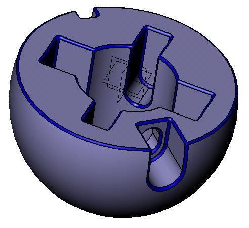
154 Fundamentals 153
155 ASSEMBLY - Bottom up approach Since all the individual parts for our fan are already constructed, we are going to show you the Bottom Up approach of assembling components. An example of the Top Down approach will be shown later. 1. Create a new Part / Assembly object and name it Fan_Assembly. Pick New Assembly Mode. Fundamentals 154

156 2. Insert the first component into the assembly. Use the RMB (Right Mouse Button), and Select the Insert Component command. Place it anywhere on the screen. (NOT 0,0,0). Select the Flange component from the list of objects. 3. We are now going to align the flange with the world XYZ Datum planes. Key to successful aligning: Put your filter on face and RMB on-entity. It is not necessary to pick an alignment icon from the optional inputs section of the form. If you pick a cylindrical surface, ZW3D assumes a concentric constraint; a flat face, we assume coincident. Select the bottom face of the counter bore as shown. Look for the rectangular constraint icon before picking. Select the XY plane. Notice the component moves. Select the same facing option. Notice the component reverses its direction. Don t hit OK yet. You will be picking 3 pairs of faces or planes to fully constrain most objects. If you do hit OK prior to completing the alignments, just Right-click > Align. You can switch between opposite and same facing until you pick the next face. Fundamentals 155

157 Notice that the centerline of the component is not aligned with the Z axis of the world plane. Also notice that there is now a Planar constraint shown. We now need to be able to see the datum planes of the component. 4. Pick the View > External Datums command. 5. Let s create our second alignment constraint. Select the component s YZ plane. Select the Opposite facing option. Select the world YZ plane. Fundamentals 156
158 Your component should now look like the training image. Fundamentals 157
159 6. Third and final alignment constraint. Select the XZ plane. Select the same facing option. Select the world XZ plane. Select OK. Fundamentals 158

160 7. The component should look like the training image. Use the Inquire Alignments command on the Assembly Tab to examine the constraint system. Select the Cancel button from the Show alignment status form. Fundamentals 159
 Select the Tube component from the list of objects.")
161 8. Let s insert a second component. Select the Insert Component command.(right click> Insert Component) Select the Tube component from the list of objects. For the origin, pick a location away from the Flange. Zoom All. Fundamentals 160
162 9. We will now align the Tube with the Flange. Select the outer cylindrical face of the Tube. Select the Opposite option. Select the inner cylindrical face of the Flange component. Fundamentals 161

163 10. Select the face from the cross hole in the Tube component (filters may be necessary). Select the Opposite facing option. Select the face from the cross hole in the Flange component. You have now eliminated all 6 degrees of freedom. The part can t move in X, Y or Z and can t rotate about X, Y or Z either. Select OK. Fundamentals 162

164 11. Turn the shading on. Your display should now look like the training image. Fundamentals 163

165 12. Now we will insert another component. Select the Insert Component command. Select the Flange Pin component from the list of objects. For the origin, pick a location away from the assembly. Fundamentals 164

166 13. Again, this component needs to be aligned. Select the cylindrical face on the Flange Pin component. Select the Facing option that is appropriate for this component. Select the inside hole face from the Flange component. Fundamentals 165

167 Your assembly should now look like the training image. Fundamentals 166

168 14. Now we will make the head of the pin tangent to the flange. Select the mating face from the head of the Flange Pin component (filters may be necessary). Select the Opposite facing option. Select the Tangent icon from the Optional Inputs. See the figure above. Select the outer cylindrical face from the Flange component. Fundamentals 167


169 15. Turn the shading on. Your display should now look like the training image. Try to define a rotational constraint on the Flange Pin. Note: Pick the hole in the flange pin as the first entity, pick the angle icon and pick the YZ plane as the second entity. (input 45 degrees), Fundamentals 168

170 16. Now let s insert the Pin. Select the Insert Component command. Select the Pin component from the list of objects. Select an origin away from the assembly. Fundamentals 169

171 17. We need to align this component also. Select the cylindrical face on the Pin component. Select the inside hole face from the Tube component. Select the Opposite facing option. Fundamentals 170
172 18. Now we will use a point constraint to determine the insertion depth of the Pin. Select the right face of the cylindrical face on the Pin component as shown(filter on Face). Select XZ plane on the Flange_Pin component. (filter on All) Select Same facing, and type 17.5mm on Offset. Select OK. Fundamentals 171

173 Your assembly should now look like the training image. Fundamentals 172

174 19. Let s insert one more component and align it. Select the Insert Component command. Select the Ball component from the list of objects. Select an origin away from the assembly. Fundamentals 173

175 20. To align: Select the inner cylindrical face on the Ball component as shown. Select the Opposite option. Select the outer face of the Tube component Pick OK. Fundamentals 174


176 21. To align: Select the cylindrical face on the Ball component as shown. Select the outer cylindrical face of the Pin component. Select the Facing option that is appropriate for this component. The slot in the Ball is now concentric with the Pin. Fundamentals 175

177 Your assembly should now look like the training image. Fundamentals 176

178 22. Use the View/External Datums button to remove the Datum Planes from the display. 23. Turn the shading on. 24. Select the File/Save File command, and save your assembly. Fundamentals 177
. Click Next to cycle through the individual components.")
179 25. Let s check alignments before going on. Use the Inquire Alignments command again. Look at the color coded graph to help interpret the results. You will see that all the components are Well Defined except the Support Pin. It has 1 rotational dof (degree of freedom). Click Next to cycle through the individual components. Think about what the pin does. We really don t care that it can rotate so leave it alone. The flange pin would also be able to rotate except we gave it a specific angle alignment. Fundamentals 178
180 26. Let s create an intentional interference condition and have the system check it. Use the RMB and select ZW3D Manager (if it s not already displayed). Now select the Assembly Manager icon tab. select the Ball component from the tree, right click on it and select the blank option. Blank the Support Pin and Tube components. Fundamentals 179
181 27. Modify the Flange Pin geometry. Double click on the Flange Pin Component. (Pick filter set to all). You are now in the Flange Pin object. Select View > Show Scope > Show Target to only display geometry in the active object. Double click on the long cylindrical surface of the Pin. Double click on the Dia 6.0 dimension and change the value to 10. The part history will automatically regenerate. Fundamentals 180

182 28. Going back to the Assembly. Select the Show All icon from the Document Awared toolbar to display all of the geometry. Select the Exit part button to return to the Assembly. Fundamentals 181
183 29. Select the Interference Check icon from the Assembly Tab. Base select the Flange. Check select the Flange Pin Check the message window for interference message. Go to the Assembly Manager again and blank all components. 30. Select the Undo command to undo the history until you are back to the Assembly (see title bar) with all components visible. Fundamentals 182
184 31. Select the Unblank All command. Your assembly should now look like the training image. Fundamentals 183

185 32. Select the Exploded Config icon from the Assembly Tab. Use the Middle Click to accept the command. Your assembly should now look like the training image. You may need to use the Move along direction command on some components to adjust their spacing. In order to manage the original and the Explode assembly, ZW3D automatically creates a new Assembly Configuration. See the Title bar at the top of the screen, it shows [Explode_Asm]. Use the Activate Configuration command shown below. You can select between the original and the exploded configurations. Using the configuration technology, ZW3D can have multiple exploded configurations. On a drawing sheet, when laying out a standard view, click on the Advanced tab > config and pick either the default or the exploded configuration. Fundamentals 184

 1. Insert pull down menu > Component (or Right Click Insert Component).")
186 ASSEMBLY - Top Down approach Our Next Project with this assembly will introduce the Top Down method of creating a part. We will create a new empty part object within the context of the assembly and we will copy geometry from other parts in the assembly to begin the construction of our new part. For the purpose of demonstrating this approach we will construct a simple gasket that would sit on the bottom of the flange as shown to the right. (Hopefully you have already been exposed to this concept in Chapter 3 of the Innovator Training manual.) 1. Insert pull down menu > Component (or Right Click Insert Component). Type in the name of the new empty Part (Flange_Gasket) on the command line as shown above and Hit <ENTER>. Then check the Anchor option from the Insert Component Options Window. You will be prompted on the command line for the insertion point. Right-click > Critical and pick the center of the hole at the top of the Flange. Fundamentals 185
![2. Your Title bar should show you that you are in the new Flange_Gasket part object that we just created. See the title bar, it shows [Part[Flange_Gasket].](/docs-images/93/111326396/images/187-0.jpg "You can also pick View > Show Scope > Show Target and you will see only the three base datum planes on the screen. 3.")
187 2. Your Title bar should show you that you are in the new Flange_Gasket part object that we just created. See the title bar, it shows [Part[Flange_Gasket]. You can also pick View > Show Scope > Show Target and you will see only the three base datum planes on the screen. 3. Next we want to copy the bottom planar face of the flange into our Flange_Gasket to use for the creation of the gasket. Pick the Show All icon from the top toolbar. 4. Insert Component > Pick Flange >, select Assembly pull down menu > pick Reference Face > set your Pick Filter to Face > select the bottom face of the flange as shown below and Middle Click or hit <Enter>. Select the Show Target icon from the top toolbar and you will see the Face you just copied and the three base datum planes on the screen. In Wireframe display, the face will have blue dotted edges representing the open edges of the face. 5. Now we need to build the gasket. We will build two separate sketches. One for the main body or outside shape of the gasket and the other for the holes in the gasket. Insert a sketch and select the face we just copied as the planar face or reference plane of the sketch. Be sure that the copy Reference face edges in the Sketch Options form is checked. Then pick OK Use the Trace command to trace the outside reference edges for your sketch Fundamentals 186
188 Exit Sketch. Insert Sketch Again, and pick the same face for your sketch with the reference face edges checked. When in the sketch select the 5 red dotted circles of the holes and Right Click and Pick Toggle Type from the Right-Click Shortcut menu. Your circles will become red solid circles. This subtle change is significant because the red circles still reference the model geometry but we can now use them when we leave the sketch. Your sketch should look like the following figure. Exit Sketch. 6. Next, Erase the Face that you used to generate these sketches 7. Extrude the first sketch that you made for the Base shape of the gasket. Fill in the option form as shown. Start = 0 End = 1 Offset = Shrink/Expand -> 2.00 Fundamentals 187

189 8. Extrude Remove the second sketch to create the holes in the gasket. Fill in the Options as shown. Start=0 End = Through All Offset = Shrink/Expand -> 1 Pick OK to complete the Extrude Cut. As shown below. Fundamentals 188


190 9. Your result should look like the following. Pick Show All from the Document Awared toolbar. Right-Click > Exit Part. And you will be returned to the main Fan Assembly Object. 10. Now let s edit the Flange to see changes update in the Flange Gasket. Set your entity filter to Component and double click the Flange. Your title bar should show that you are in the Flange Part and if you pick the Show Target you will only see the flange. Open the History Window of the Flange (CTRL-H). Right Click on Sketch2 and choose edit. Change the 40mm Radius Dimensions to 43. Exit Sketch. The history will automatically regen. Then Exit part. Fundamentals 189


191 Check your title bar to see if that you are at the parent assembly. Your assembly should look like the following figure. The Flange Gasket has not updated, yet. Set your entity filter to Component and Double click on the Flange Gasket. You are now editing the flange gasket. Pick the Regen Button. Your Flange Gasket should have updated and looks like the following image. Exit part. Fundamentals 190

192 As an additional exercise, let s create the flange gasket a different way. 1. Make sure you are at the Assembly level and not in a component part. (see title bar) 2. Blank the Flange Gasket component from the assembly. 3. Insert Component Name it Flange_Gasket-2 anchor and position at zero. 4. Insert Component > Pick Flange > select Assembly, pull down menu > pick Reference Face > set your Pick Filter to Face > select the bottom face of the flange as shown below and Middle Click or hit <Enter>. 5. This time we will use the Shell command from the Shape Tab. Pick the open surface. Make the thickness -2.0 Since we want to add material to the blue side of the surface it will be a negative thickness 6. Use the Face Off command and add 2mm to the 8 outside surfaces shown below. 7. Repeat this command and add a negative 1.0 to the 5 holes. This will make the holes larger. 8. Select Show All to view the entire assembly. 9. You may want to change the face attribute of your new shape. 10. Now, let s go back and change the thickness of the gasket to one. Right-click on Shell and select Open/Close. Right-click on Thickness and select Edit. Change this to 1.0. Fundamentals 191

193 The History will automatically regen. Fundamentals 192
194 Day 2 Chapter 6 Datum Planes and Reference Geometry Fundamentals 193

195 Datums Datums are used to establish a plane of reference. A datum plane or a planar part face can define them. When a sketch is created, you are prompted to select an insertion plane. When you select a datum plane or planar face, the sketch is aligned with the plane and sketch geometry is created on the plane. The sketch is parametrically constrained to the plane on which it is created. If the plane moves, the sketch will move with it during the next history replay. There are three default datum planes as shown below. 1: Default Datum Planes 2: World Origin and Traid Datum planes are also used to create certain features that do not require the use of a sketch such as parting lines and section curves. The Insert Datum Plane command creates datum planes using a variety of methods. In this discussion you have learned that: Datums are planes of reference used to locate sketches and create features. Datums can be datum planes and planar part faces. There are three default datum planes located at the world origin. Datum planes can be created using the Insert Datum Plane command. 1:Default Datum Plane 2:Planar Part Face 3: New Datum Plane Fundamentals 194
196 Refer to the HELP Manual Refer to the and review the following commands. Datum Plane - About Datum Plane - Insert Datum Plane Make Local Datum Plane - Mirror Datum Plane Toggle External Create External Reference Geometry Menu - Sketch Level( Insert> Reference Geometry) This menu contains commands for creating external reference geometry in a sketch. External refers to geometry that is referenced from outside the active sketch plane. Using external references will allow sketch geometry to adapt to changes made to the active part or other components in the case of an assembly. ZW3D uses several terms that that are related but do have separate meanngs. "Datum Plane" refers to a database entity that defines a plane. "Plane" refers to any specification of a plane in space, whether or not it is a datum entity (i.e. a planar face pick, +X, -X, +Y,...). "Frame" is used when 3D coordinates are of being talked about as opposed to something happening on a "plane". Fundamentals 195
197 Refer to the HELP Manual Refer to the HELP Manual and review the following commands. Project - a Reference Curve Project - a Reference Face Project a Reference Point "F7" Toggles - Curve Type Toggles - Display Toggles - Perspective View Toggles (View) Labels Toggles - Display (On by default) Toggles - Dimensions (On/Off) (Ctrl+D) Toggles - External Datums (Off by default) Toggles - Grid On/Off (Ctrl+G) Toggles - Line Limits (On/Off) Toggles - Construction Geometry (On/Off) Toggles - Sketch Constraints Input Options (Index) Input Options Menu Fundamentals 196
198 Chapter 7 Creating Holes, Fillets and Chamfers Fundamentals 197
199 Refer to the HELP Manual Refer to the HELP Manual and review the following commands. Hole - Simple Fillet - Constant Radius Fillet - Elliptical Fillet - Face Chamfer - with 1 setback Chamfer - with 2 setbacks Chamfer - at Vertex Shell Offset - Volume Offset Face of a shell Fundamentals 198
200 Lesson 7 Creating Placed Features Fundamentals 199

201 OPEN the file Fundamentals.Z3 Follow the instructions supplied in each object to create the required fillet. Edit the object Fil_Box_Shape_with_Cutout. Change the display to wireframe if it is not already. This will allow you to see the edge geometry that the instructions will refer to. After completing the fillets on this part change it back to the shaded mode to get a better look at your results. In this example we will show how ZW3D can generate fillets that will extend beyond a selected face. Fillet the RED edge 12mm. Fillet the GREEN edge 30mm. Exit Part. Edit Fil_Conic. Set the display to wireframe. Fillet the RED edge 30mm with a conic ratio of 0.5. Change ARCTYPE to Conic. Fillet the GREEN edge 30mm with a conic ratio of 0.7. Pick ARCTYPE to change its value. <Right-click> Redefine Last and change the conic value to 0.9. Notice the increase in the sharpness of the fillet. Fundamentals 200


202 Exit Part. Edit Fil_D_Shape. Pick the Set Origin command. <Right-click> On Face and pick the top face of the middle object as shown in the figure below. RMB-Drag to rotate and MMB-Drag to pan the view of your model as shown in the figure below. Notice as you rotated the view that the rotation point was about the point you defined in the previous step. This view orientation will make reading the directions for each fillet example easier. Fundamentals 201

203 Fillet the RED edge 10mm. Fillet the GREEN edge 30mm. Notice the vertical faces disappear. For the 3 rd shape, use Fillet with any size radius and the fillet command will pickup on the existing variable fillet attributes. Exit Part. Edit Fil_Dog_bone_shape. Fundamentals 202


204 Fillet the RED edges 10mm. This will generate a tangent condition between the fillet and the faces it is attached to as shown in the left figure below. UNDO the last command after you have evaluated the results. This time Fillet the RED edges to 20mm. This will generate a non-tangent condition between the fillets and the faces they are attached to as shown in the right figure below. The purpose of this step is to show how ZW3D can create overlapping fillets and adjust to the condition. Notice in the figures above how the fillets in the left image are tangent to their adjacent faces, and the fillets in the right image are tangent to the vertical faces and intersecting each other at the top. Create a 5mm fillet along the top edge where the two fillets intersect. Fillet will fail if you try to make this one too large. Play around a bit with this thought. Make sure when you finish playing that you have a 5 mm fillet along the top. Pick the Fillet command again and <Right-click> Pick All to pick the entire model. Create a 2mm fillet on all remaining edges. Your model should appear as shown in the figure below. Fundamentals 203

205 Exit Part. Edit Fil_Face_Remove. Fillet the RED edge 25mm. Fillet the GREEN edge 12mm. See following figure for results. Create a variable fillet with the fillet attributes shown. Fillet the WHITE edge 12mm. See following figure for results. Fundamentals 204

206 Exit Part. Edit Fil_L_Shape. For PARTS 1 through 3 apply the fillets in the following order. In this step we are going to demonstrate how ZW3D generates fillets based on the order and method you attempt to apply a fillet. Fillet the RED edge in all 3 parts 10mm. Fillet the GREEN edge in all 3 parts 10mm. Fillet the WHITE edge in part 1 10mm. Fillet the WHITE edge in part 3 10mm. UNDO the last step. Fillet the white edge in part 3 10mm using the chain pick method this time. Hold your <SHIFT> key down to pick the white edge. Notice the difference in the appearance of the fillet by using the chain pick method in part 3 compared to the method used in part 1. Fundamentals 205
207 Exit Part. Edit Fil_Setback. Apply next few steps to the left part. Fillet the RED edge 10mm. Fillet the GREEN edge 20mm. Fillet the WHITE edge 30mm. See left figure below for results. Pay attention to the result of the corner fillet. In the following step we are going to apply some control to that corner using the RELIEF option. Apply next few steps to the middle part. Fillet the RED edge 10mm. Fillet the GREEN edge 20mm. Now we are going to apply a fillet to the WHITE edge using the RELIEF option. Fillet the WHITE edge 30mm with a RELIEF of 10. See right figure above for results. The higher the setback (relief) value, the more smoothing you will see at corner patches. <Right-click> Redefine Last and change the RELIEF to 20 and again to 25 to better understand this option. If the Redefine Last command responds with The last operation did not create a feature, highlight the last fillet you created and <Right-click> Redefine. Exit Part. Fundamentals 206

208 Begin a new part and name it FILLETING. Pick the Block command from the Shape Tab. Pick (0,0,0) for the 1 st point. Pick any other point on the screen for the 2 nd point. Change the Length, Width and Height values to 90. Pick OK. Your current model should be a simple cube, 90mm x 90mm x 90mm. We are using a very simple part in the example so we can focus on the filleting options we are about to learn instead of getting bogged down with complex geometry. Let s begin applying some fillets to the corners. Pick the Fillet command from the Shape Tab. ZW3D can fillet all edges of a model in one command using any of the various entity selection methods. <Right-click> Pick All. Dynamically adjust the fillet radius to a reasonable size by picking the up or down arrows in the options form. ZW3D will verify that all edges can accept the fillet size you attempt to create. If the fillet fails when attempting to fillet all edges, try a smaller fillet. Your model should appear similar this. Pick the Turn dimensions ON/OFF command from the Document Awared toolbar. The dimensions should appear in your model as shown in the figure below. Fundamentals 207
209 Go to the Edit pull down > Preferences. Change the units to inches. The dimensions on your screen should update automatically to reflect inches. If they do not, try a redraw F5. Pick UNDO from the utilities toolbar until the fillets you created are gone. This will also set the units back to millimeters. Pick the Fillet command. Pick 3 edges to create the fillets as shown in the figure below. Specify the Radius to be 10mm. Corner Radius without Relief Let s make a change to the fillets we just created. Fundamentals 208
210 <Right-click> Redefine Last. Set the Relief option 10. The Relief option is used to control the amount of smoothing at a corner patch. With the relief set to zero (its default value), the filleting algorithm decides where to trim the rails of the fillets meeting at a corner. Compare these results with the figure above. Corner Radius with Relief = 10 In this next example we are going to use options that allow us to control the fillet in a free form manner of speaking. Pick UNDO to remove all fillets from your model. Pick the Fillet command again. DO NOT pick the edges. Change the radius to 15 and hit <ENTER> on the keyboard. Pick the Vertex define button in the Advanced options form. Pick the vertex shown in the left figure below as the Vertex to Fillet. Vertex allows you to pick a corner to be filleted instead of having to pick three edges. Note: The edge radius displayed in the options form works in conjunction with the vertex fillet radius that will be displayed in the next form. The value of the vertex fillet is 1.5 X the edge radius. You can go higher for more smoothing. A lower value may give undesirable results. Specify a value and hit OK or use the up and down arrows. Fundamentals 209
211 Pick the RIGHT edge and specify a relief value by adjusting the Up and Down arrows. Pick the LEFT edge and specify a relief value by adjusting the Up and Down arrows. Pick the MIDDLE (Vertical) edge and specify a relief value by adjusting the Up and Down arrows. Complete the command to review your results. Completed fillet with setback (relief) values of 55, 35 and 40 In the final step of this lesson we are going to modify the face setback (relief) of the fillet just created. The FACE option allows for explicit control over the face setback at the spherical radius of corners. This control is independent of the fillet radius. This option allows you to design a corner patch and see it echoed on the part before the fillet operation is complete. The corner patch can be edited before the fillet is complete by selecting the Vertex option again and then selecting this Face option again. It can be edited afterwards with the Redefine Feature command. Highlight the fillet just created. <Right-click> Redefine Last. Pick the Vertex Define button in the form. Pick the same vertex. The fillet that you are in the process of redefining should preview on the model. <Middle-click> at the radius option to display the face options form shown below. Pick the Face Define button from the form. Fundamentals 210
212 Pick the TOP face and specify a face relief value of 25. Pick the Face Define button from the form again. Pick the RIGHT face and specify a face relief value of 30. Pick the Face Define button from the form again. Pick the LEFT face and specify a face relief value of 28. Complete the command and review your results with the following figure. Completed Model Finished. Exit Part. Begin a new part and name it WHEEL. Pick the Revolve command. Pick the XZ Plane for the new sketch. Create the sketch shown in the figure below. Since we have done a lot of sketching already, we will leave the method for creating this sketch up to you. Just three points we would like you to adhere to. Fundamentals 211
213 Add the dimensions as shown in the sketch. Match all dimension values. Create an Anchor constraint at 0,0. Use the Constraint Status command to verify your sketch is well defined. <Right-click> Exit Sketch. The values for the revolution are: Method: Base. <Right-click> Z-Axis for the revolve axis. Start = 0, this is the default value, so you can <Middle-click>. End = 360, this is the default value, so you can <Middle-click>. Fundamentals 212
214 Let s create the mounting hole in the center portion of the wheel as shown in the following figure. Pick the Extrude command and create a new sketch. Turn Reference face edges on in the options form. Pick the TOP face parallel to the XY Plane for our new sketch. Do not pick the XY plane. Create the sketch shown in the following figure. Again, since we have done a lot of sketching already, we will leave the method for creating this sketch up to you. Here are a few helpful hints though: Our sketch was created using 3 commands, Circle - boundary method, corner rectangle and Trim. Add the necessary geometric constraints and dimensions. Modify all dimension values to match. Pick the Show Target command from the Document Awared toolbar to display your sketch. Fundamentals 213
215 <Right-click> Exit Sketch. The values for the extrude are: Method: Remove. Start = 0. End = <Right-click> Thru All. (We could also use Boundary Face and pick the bottom face.) No Draft Angle. Fundamentals 214
216 Create a 5mm fillet on the top and bottom edges of the mounting hub as shown in the figure below. Let s create a sweep path for the first wheel spoke. <Right-click> Insert Sketch. Pick the YZ Plane or type YZ in the command prompt for the new sketch. <Right-click> Draw and create the line shown in the following figure. <Right-click> Dimension the entire sketch as shown in the figure below. Match all dimensions. <Right-click> Exit Sketch. Fundamentals 215

217 To complete the first spoke we need to create the sketch to sweep through the line we created earlier. Pick the Sweep Shape command. Middle-click to create a new sketch. Pick the XY Plane for the new sketch. Create a circle with a Radius of 10. Place the circles center at 0,0. <Right-click> Exit Sketch. The Sweep command continues asking the necessary questions to finish up. Notice the circle we just created is already highlighted without picking it. ZW3D automatically uses this sketch as the cross section for our swept feature. Pick the line we created earlier for the sweep path. Change the Frame to Selected in the Advanced Options form. Select the top face of the wheel hub. Change the Sweep type to Add. Pick OK to complete the command. Fundamentals 216


218 Natural - The default reference frame of the profile or entity is used to control the sweep along the curve. The sweep begins at the start of the curve path. At Profile - The frame is built on the point on the sweep path where the profile is. This will make the surface interpolate the profile but the profile will not be at the beginning of the surface. At Path - The frame is built at the start of the sweep path. Selected - You are prompted to select a datum plane or part face whose default reference frame will be used to control the sweep. The reference frame and the entities being swept are theoretically joined as a rigid body. The reference frame is then moved to the start of the curve path. Fundamentals 217
 <Right-click> Z-Axis for the axis of rotation. Fill in the Number and Angle as shown at right. Pick OK.")
219 Pick the Pattern command from the Shape Tab and then select the Circular method from the Required Inputs section of the Options Form. (see form below). Pick the spoke as the feature to pattern. (set filter to feature) <Right-click> Z-Axis for the axis of rotation. Fill in the Number and Angle as shown at right. Pick OK. The following is an example of a circular pattern using the second number and spacing fields. Fundamentals 218
220 Create a fillet, R=5 at both ends of all the spokes. Press and hold the <SHIFT> key while you pick to chain pick all tangential edges. If you need to unpick an entity, use <CTRL> Pick and pick that entity. The final operation for our wheel design is to cut a hole through the handle portion as shown in the figure below. Pick the Extrude command from the Shape Tab. Activate the XY Plane for the new sketch. Create a circle. Fundamentals 219
221 Radius 10mm. Center point at 100,0. Or add Constrain points horizontal. <Right-click> Dimension. Add the 100mm horizontal dimension. <Right-click> Exit Sketch. The extrude option form should reappear. Pick the Remove option. Specify the Start to be 65. Specify the End to be 0. Create 2mm fillets at the edges of the hole. Fundamentals 220
222 Save and exit the part. Fundamentals 221
223 Chapter 8 Working with Multiple Components Fundamentals 222
224 Refer to the HELP Manual and review the following commands. Insert Component Component Merge into Active Part Combine (Add, Remove, Intersect) Shapes Trim Shapes Divide Shapes Replace Faces Tie Off Self-intersections Sweep Simple Shape To Create a Rod Variable Shape Variational shape Pattern (3D) Mirror (3D) Move Along a direction Point to point Punch Fundamentals 223
225 Lesson 8 Working with Multiple Components Fundamentals 224

226 Designing a Blow Mold This exercise will take you through several ZW3D commands to design a blow mold as shown in the figure below. The bottle we will use for this example is a fully parametric model created in ZW3D. It could also be an IGES file or Point Cloud file you might receive from your customer. OPEN the ZW3D file Fundamentals.Z3. Pick the Part/Assembly icon from the ZW3D root to create a Part object. Name it Blow_Mold. We will begin by inserting the component called Bottle. This is the bottle that the blow mold will be designed for. It is an existing ZW3D object. If you would like to view how it was designed in ZW3D, OPEN this object and Step Thru its History. <Right-click> Insert Component. Pick Bottle from the File/Part list of the Options Form. From the keyboard, type,, to insert the bottle at 0,0,0 or <Left-click> at 0,0,0. The 0,0 origin in the source object will be placed at the 0,0 origin in the destination object. Uncheck Align after insertion from the Optional Inputs form. Pick OK to accept the settings. Your screen should display the bottle as shown in the following right figure. Fundamentals 225

227 The next thing we want to do is adjust the orientation of the bottle to suit our model designers requirements relative to machining. We want to rotate the bottle about the X and Y-axes. Pick the Move entities along a direction command within the Move command under the Assembly Tab. Verify that your pick filter is set to Component or All. <Shift><Right-click> to verify. For Entities to Move, pick the bottle. This can be done with a single pick due to your pick filter. For the Move Direction, <Right-click> X-Axis. Distance is 0. Remember; you can <Middle-click>. Angle is -90. Pick the increment or decrement arrows to view the rotation dynamically. Remember positive rotation is CCW and we are rotating about the positive X-Axis. For the Rotation Direction, pick the appropriate increment or decrement button until the value is 90 degrees. Remember positive rotation is CCW about the axis. <Middle-click> to restart the Move entities along a direction command. Pick the bottle shape again. Set the Distance to 0. Set the angle is -90 degrees about the Y-Axis. Complete the command. See figure below for final results. Fundamentals 226

228 The next step is to begin modeling the stock from which we will cut the cavity. <Right-click> Insert Sketch. <Middle-click> to accept all of the defaults. Pick the Rectangle - Corner command from the Sketch Tab. Draw and constrain the rectangular sketch as shown in the figure below. The grid can be turned off if you prefer or left on. You decide. Some suggestions that will help in the constraining process are: Apply the necessary dimensional constraints by using the <Right-click> Dimension or. Press the F7 function key to attach dimensions to model edges. F7 instructs ZW3D to snap to critical points anywhere in the active part or assembly. Do not use the Auto-Constrain command as your first choice for constraining. This will create constraints that might be undesirable for this particular design. A good rule of thumb to follow with Auto Constrain is to manually create the required geometric and dimensional constraints first. If the sketch still requires some constraints, use the Auto Constrain command to finish the process by <Right-clicking> Constrain. Press F7 to pick the top edge of the model when dimensioning to it. As indicated below. Fundamentals 227

229 Pick the Constraint Status command to verify the sketch is well defined. When finished constraining the sketch, <Right-click> Exit Sketch to return to the model mode. Pick the Extrude command from the Shape Tab to extrude the rectangular sketch. Set the start to be 0 and the end to be 91 and no Draft angle. <Middle-click> or pick OK to complete the command. Your model should appear as shown in the following figure. The bottle component we inserted earlier is still associated to its source (parent) object. If that source object is changed, this model will update to reflect those changes. Merging allows us to edit this component in the current part. Place your cursor over the bottle to highlight it. Fundamentals 228
230 <Right-click> Merge. Method: Remove. Pick the bottle as component. <Middle-click> or pick OK to complete the command. Let s review what we have done so far. History Play. Pick the Replay next operation button located in the bottom of the History Manager. Replay each operation one at a time as a review of what you we have accomplished so far. Each time you pick this button, you will see a feature taken from the pending window and moved up to the features window. Keep in mind that at any time during this history replay you can make changes to the design by adding, removing or editing features. We will talk more in depth about the stepping thru history later. Next we are going to design the push up area and the bottle top area of the blow mold. <Right-click> Insert Sketch. Adjust the options form and pick the top face of your design as shown in the figure below. The Reference face edges option tells ZW3D to extract only model edges that are coplanar to the face you are picking. The model edges will appear as hidden or dotted lines on your model and can be used to assist in building other sketches or can actually become part of another sketch. A similar command to the Edges option is Project Reference Curves. This command creates Construction Geometry curves on the active sketch plane by projecting 3D curves. 3D curves could be lines, arcs, curves, or edges. If an edge is modified, all projected construction geometry from that edge will update the next time the active part or sketch is updated. Fundamentals 229
231 Pick View > Show Scope > Show Target from the top pull down menu to simplify the display while constraining the sketch. Create and fully constrain the sketch as shown in the following figure. Keep in mind that you might have to erase some dimensions and geometric constraints to achieve this. These are some of the commands you might consider using. the icon or use the <Right-click> menu to access these commands. Pick Use the Default snap option (<Right-click> Default) to snap the top horizontal line to the top reference edge. Well defined sketch Fundamentals 230
232 Pick Constraint Status to verify the sketch is well defined. <Right-click> Exit Sketch. Pick the Extrude command. Pick the Remove icon in the options form. Pick the sketch you created in the previous step. For the Start specify 0. For the End specify 32. Next we are going to design the push up area and the bottle bottom area of the blow mold. <Right-click> Insert Sketch. Adjust the options form and pick the top face of your design as shown in the figure below. The Reference face edges option tells ZW3D to extract only model edges that are coplanar to the face you are picking. The model edges will appear as dotted lines on your model and can be used to assist in building other sketches or can actually become part of another sketch. A similar command to the Edges option is Project Reference Curves. This command creates Construction Geometry curves on the active sketch plane by projecting 3D curves. 3D curves could be lines, arcs, curves, or edges. If an edge is modified, all projected construction geometry from that edge will update the next time the active part or sketch is updated. Pick View > Show Scope > Show Target from the top pull down menu to simplify the display while constraining the sketch. Create and fully constrain the sketch as shown in the figure below. Keep in mind that you might have to erase some dimensions and geometric constraints to achieve this. These are some of the commands you might consider using. the icon or use the <Right-click> menu to access these commands. Pick Fundamentals 231
233 Well defined sketch <Right-click> Exit Sketch. Pick the Extrude command. Pick the Remove icon in the options form. Pick the sketch you created in the previous step. Set the Start 0. Set the End 76.2 with no draft angle. In these next few steps we are going to design a left and right pinch off for the mold as shown in the following figure. To do this we will borrow from some existing geometry and build the rest. Fundamentals 232
234 Top left Face for Left Pinch off Design Top right Face for Right Pinch off Design Designing a Pinch Off <Right-click> Insert Sketch. Turn Reference face edges on. Pick the top left face of your design. Refer to the figure above to determine the appropriate face. Create and fully constrain the rectangular sketch shown in the figure below. These are some of the commands you might consider using. use the <Right-click> menu to access these commands. Pick the icon or Notice in this figure the hidden or dotted lines. These are the edges extracted from all model edges coplanar to the sketch plane (face) you picked. We are going to use these edges in combination with the rectangular sketch to build the final sketch for extruding. Pick View > Show Scope > Show Target from the top pull down menu to simplify the display while constraining the sketch. Next we are going to use some of the model edges and the rectangular sketch to determine our final sketch. Fundamentals 233
235 Pick the Create Trace Profile command from the Sketch Tab. Pick near the 2 points as shown in the figure below to create the trace profile. Your final sketch should appear as shown by the thicker lines in the figure below. Trace profiles are parametric. They are associated to the model edges. As these model edges change, trace profiles update to reflect thee changes. <Right-click> Exit Sketch. Pick the Extrude command. Pick the Remove icon in the options form. Pick the trace outline you just created. Set the Start to 0. Set the End to 3 (may be +3). Set the Draft Angle to 16 degrees. Pick the Offset option and set it to Shrink/Expand. Fundamentals 234
236 Set the Offset distance specify -.4. Your model should appear as shown in the figure below. Let s create the Pinch Off for the other side. <Right-click> Insert Sketch. Turn Reference face edges on. Pick the top right face of your design. Create and fully constrain the rectangular sketch shown in the figure below. These are some of the commands you might consider using. use the <Right-click> menu to access these commands. Pick the icon or Notice in this figure the hidden or dotted lines. These are the edges extracted from all model edges coplanar to the sketch plane (face) you picked. We are going to use these edges in combination with the rectangular sketch to build the final sketch for extruding. Fundamentals 235
237 Pick View > Show Scope > Show Target from the top pull down menu to simplify the display while constraining the sketch. Next we are going to use some of the model edges and the rectangular sketch to determine our final sketch. Pick the Create Trace Profile command from the Sketch Tab. Pick near the 2 points as shown in the figure below to create the trace profile. Your final sketch should appear as shown by the thicker lines in the figure below. Trace profiles are parametric. They are associated to the model edges. As these model edges change, trace profiles update to reflect thee changes. Fundamentals 236
238 <Right-click> Exit Sketch. Pick the Extrude command. Pick the Remove icon in the options form. Pick the trace outline you just created. Set the Start to 0. Set the End to 3. Set the Draft Angle to 16 degrees. Pick the Offset option and set it to Shrink/Expand. Set the Offset distance specify -.4. Your model should appear as shown in the figure below. Fundamentals 237
239 Let s create the 2 holes as shown in the following figure. Pick the Hole command from the Shape Tab. Hole type = Simple; Dia = 38.1; End = Thru-All. See other fields in next step. Place the Holes on the top face of the Blow Mold as shown in the following figure. For the Hole Locations <Right-click> From 2 Lines. Pick the outer 2 edges to align the 1 st hole from as indicated in the following figure. The holes will be 25.4mm from both edges. Carefully follow the command prompts. Pick the outer 2 edges on the other side of the blow mold to align the 2 nd hole from as indicated in the following figure. The holes will be 25.4mm from both edges. Carefully follow the command prompts. <Middle-click> to accept the remaining default prompts. Fundamentals 238
240 1: Pick this Face to place the holes on. 2: Pick these 2 Edges to place the 1st hole. 3: Pick these 2 Edges to place the 2 nd hole. See the result below. Let s create the mounting holes for the push up as shown in the following figure. Pick the Hole command from the Shape Tab. Hole type = Simple; Dia = 19.1; End = Thru-All. See other fields in next step. See the result below. Fundamentals 239
241 Place the left most hole on the face indicated in the following figure. For the Hole Locations <Right-click> From 2 Lines. Pick the 2 edges to align the 1 st hole from as shown in the following figure. Place the hole 25mm from the left edge and 22.5 from the front edge. 1: Pick this Face 2: Pick these edges Let s create copies of the hole for a total of four. Pick the Pattern command from the Shape Tab and then select the Linear method icon from the Required Inputs section of the Options Form. For the Features to pattern, pick the hole you just created. For the direction of the Pattern you have a couple choices. You could <Right-click> X-Axis or you could pick the linear edge that defines the length of the opening the hole is in. Pay attention to the direction vector that appears when picking an edge. Fundamentals 240
242 If you pick the linear edge, make sure you pick it at the correct end. A direction vector will appear indicating which way the pattern will be placed. The Total number of features will be 4. The Spacing between each feature is to be 65mm. <Middle-click> to accept the remaining defaults. Your model should appear as shown in the figure below. Let s verify the location of the holes with one of the measuring commands available in ZW3D. Select Inquire > Distance > Point Point. Measure the distances between the Hole centers and the edges. Measure a few areas on the model to familiarize yourself with this command and its result form. After creating the alignment holes we can notice a slight error in our design. Look at the figure of the blow mold above to see what we are talking about. The left alignment hole is too close to the cutout defining the left pinch off. Let s adjust the sketch for the left pinch off so there is more clearance between the hole and the cutout. <Shift><Right-click> and make sure your pick filter is set to ALL. Right-click Edit on Sketch4. This command does not step through the history but does open the sketch for edit. You can see the entire part. We need to adjust the 45mm dimension to 65mm and the 110mm dimension to 90mm. There are several ways we can go about fixing this design problem. We could step through the history and Edit the sketch for the left side pinch off. Right-click Redefine on Sketch4 in the History list. This will step through the history automatically and stop with sketch4 open for you to edit. Then exit. Fundamentals 241
243 We could leave our pick filter set to ALL, highlight the entire sketch and double click on it. This will activate the sketch. Then we double click on the dimensions to change their values. Using this technique, when you edit the first value the entire history will automatically regen. You will have to repeat the procedure for the second value. Or Start by using technique 4 above but after you double click on one of the dimensions, click on the Delay Solve button. Make the first edit. Double click on the second dimension; now turn the Delay Solve off. The history will now regen with both changes. Your model should appear as shown in the following figure. Let s finish our blow mold design by adding some alignment grooves. <Right-click> Insert Sketch. Pick the top face of the blow mold for the new sketch. Turn Reference face edges off. Pick the Curve Reference command from the Tools Tab. Pick the left and right edges of the blow mold. See figure below for reference. You will see the hidden or dotted lines on the left and right of the blow mold. Curve Reference projects reference geometry and extracts those edges so we can use them during the constraining process of our sketch. Fundamentals 242
244 Create and fully constrain the rectangular sketch as shown in the following figure. These are some of the commands you might consider using. the icon or use the <Right-click> menu to access these commands. Pick <Right-click> Exit Sketch. Pick the Extrude command. Pick the Remove icon in the options form. Pick the sketch you just created. Set the Start to 0. Set the End to 3 with no draft angle. Complete the command. Let s complete our design by creating the other 3 grooves. Fundamentals 243
245 Pick the Pattern command from the Shape Tab and then select the Linear method from the Required Inputs section of the Options Form. icon Pick the groove you just created. For the direction of the Pattern you have a couple choices. You could <Right-click> Y-Axis or you could pick the linear edge that is parallel to the Y-Axis. You decide. If you pick the linear edge, make sure you pick it at the correct end. A direction vector will appear indicating which way the pattern will be placed. The Total number of features will be 4. The Spacing between each feature is to be 50mm. Your model should appear as shown in the figure below. Completed Blow Mold Fundamentals 244

246 Designing a Telephone This exercise will take you through several ZW3D commands to design a telephone as shown in the figure below. You should be familiar now with where most of the commands are located. OPEN the ZW3D file Fundamentals.Z3. Pick the Part/Assembly icon from the ZW3D root to create a Part object. Name it Telephone. Pick the Extrude command and create a default sketch. Pick the Rectangle-Corner command. Create the sketch shown in the following figure. Notice the geometric constraints that were automatically added to the sketch. Fundamentals 245
247 <Right-click> Points Create 2 points similar to those shown in the following figure. Notice the point s line up in the y direction. When creating the second point, guide ZW3D to automatically create a Points Horizontal constraint. <Right-click> Auto Constrain. Pick the lower left corner of the rectangle as the base point to fully constrain our sketch. Your dimension values may vary. That s OK. We will adjust them in a few minutes. Verify your sketch is well defined using Constraint Status. Fundamentals 246
248 Change the dimension values as shown in the figure below. Delay solving the sketch if your dimensions are not close to being to scale. Brackets [ ] will appear around each dimension to indicate that dimension has a pending change. One dimensional change may not be possible without another. Delaying the sketch solve allows ZW3D to consider all dimensional changes before updating the sketch. Remember there are a couple ways we can change dimensions in a ZW3D sketch and part. Highlight each dimension, <Right-click> Modify Value. Or Double click on each dimension to use Input Dimension Value form. Pick the Solve current sketch automatically command from the Utilities toolbar to apply all dimensional changes to the sketch. Typically this icon appears as GREEN when there are pending changes. This rule does not apply when in a sketch. Fundamentals 247
249 Create two Circles tangent to the vertical lines on the rectangle as shown below. <Right-click> Critical and pick one of the points for the center of the first circle. <Right-click> Tangent and pick the appropriate vertical line. The resulting circles should be constrained as concentric to the points. Review the figure below to be sure your sketches are similar. The geometric constraints may vary. That s OK. 1: Critical 2: Tangent Fundamentals 248
250 <Right-click> Trim. Trim away the portion of the sketch we no longer need as shown in the following figure. Remember, trimming requires that you simply pick on the part of the geometry to be removed. Don t worry about the dimension values in this step. Dimensions may have changed from vertical to horizontal to aligned. Replace any dimensions as required so your sketch appears similar to the sketch figure below. Again, don t worry about the dimension values in this step. Turn the Constraint Status command on to verify the status of your sketch. Leave it on the screen for the next several steps. Watch how ZW3D updates the sketch status as you add and remove constraints. Modify the dimensions to match the sketch shown below. Delay the sketch solve if required. Notice the vertical lines are parallel to each other. In our sketch they have parallel and perpendicular constraints associated to them. Your sketch may vary. That s OK. Erase any parallel and perpendicular constraints associated to the vertical lines. Highlight the constraint <Right-click> Erase. Use the <Alt> + pick method if required. Review the notes below if you are not familiar with the <Alt> + pick method. Note: Occasionally multiple constraints, or any entity for that matter, are located on top of one another. When the user tries to pick an entity, sometimes the wrong one is highlighted. Fundamentals 249
251 In order to correctly select the appropriate entity, the user can filter the pick using the <Alt> key. The <Alt + Pick>, picks the second entity. While selecting entities, the first valid entity pick is ignored and the second one is used. The <Alt + Pick> method can be extended by using combinations of the <Ctrl> and <Shift> keys together with the <Alt> key. If parallel constraints were applied in your sketch, you will only need to erase one of them. Notice when you highlight a parallel constraint, its associated partner constraint also highlights. Erasing one parallel constraint automatically erases its associated partner. Add the angular dimensions to our sketch as shown in the following figure. <Right-click> Dimension. Fundamentals 250
252 Change both angular dimensions to 93. Create 10mm fillets on the four corners of our sketch. Use the Chain of curves fillet command. Or <Right-click> Fillet and create four individual fillets. You decide. Note: If you use the Chain of curves fillet command, you will have a few methods for picking the available geometry to fillet. Use <Shift> pick to chain pick the entire sketch, window pick the entire sketch or <Right-click> Pick All. The fillets created using this method will be associated to one another. A single dimension will be added to the sketch that will control the size of all four fillets. Ignore the error message. It indicates that a fillet can t be added at the existing tangent points. If you use the <Right-click> Fillet method ZW3D will create four individual fillets with individual constraints. ZW3D offers two methods for picking the geometry to fillet. Pick two adjacent edges to preview the fillet or pick at the corner. Notice how your design intent is maintained. ZW3D adds the necessary geometric constraints to maintain the 40mm and 130mm dimensions. Your sketch should appear similar to the following figure. Fundamentals 251
253 Regen the sketch. <Right-click> Exit Sketch. ZW3D remembers you started this operation with the Extrude command and displays the options form for extrude. Adjust the form as shown in the left figure below to complete this operation. Start = 0, End = 15, Draft angle.= -10. When draft angle is applied to extrude type commands, ZW3D offers three Blend options that determine how fillets will be handled. Experiment with the telephone to see the differences. Fundamentals 252
254 <Right-click> Redefine last. Review the 3 blend options shown below using the options form. If Redefine last is not available, highlight the model and <Right-click> Redefine. Variable: Corners are not modified. They maintain the same convexity/concavity (default). Constant: Filleted/rounded corners will maintain the same radius. Round: Convex corners are rounded. Concave corners are not rounded. Let s move our model to the 0,0,0 origin in the database. Fundamentals 253
255 Pick the Move entities from point to point under the Shape Tab. command within the Move command Pick the telephone shape to move. For the From point, <Right-click> Critical and pick the middle point of the lower horizontal line lying on the XY-Plane. For the To point, type or pick 0,0,0. See figure below for reference. In the next part of this lesson we are going to create a swept surface to use for shaping the top of our telephone. <Right-click> Insert sketch. Pick the YZ Plane to create the new sketch on. We will begin by creating a curve through specified points. This curve will be used later as the path curve for the swept surface. Pick the Through point curve command from the Sketch Tab. Fundamentals 254
256 The start and end tangencies will remain undefined as shown in the options form below. Start and end tangencies can have optional direction vectors applied as required, but we will disregard this option for now. Specify the following co-ordinates to pass the curve through. 1. Point 0,4. 2. Point: 46,6 3. Point: 82,10 4. Point: 96,12 5. Point: 118,10 6. Point: 132,4 The curve can also be controlled by dimensions using the <Right-click> Constrain command. <Right-click> Exit sketch. Let s create a new sketch on the XZ-Plane. <Right-click> Insert sketch. Pick the XZ-Plane for our new sketch. Let s create a 3-Point Arc using the previous curves start point as the middle point of the arc. First we have to create a reference curve from the previous sketch to attach our arc to. Pick the Curve Reference command from the Sketch Tab. Pick the previous sketch. Fundamentals 255
257 ZW3D will create a reference curve that is associated to the sketch and project it to the XZ- Plane. As changes are made to the original sketch, the reference curve will update. Remember reference curves are red dotted or dashed curves. See figure below for reference. Verify your model to see this reference curve was successfully created. Now let s create the 3-Point Arc. Pick the Arc command and then select the 3-Point method from the Required Options section of the form to create an arc through 3 points. Specify the Start point: -40,0 Specify the Endpoint: 40,0 For the point on the arc, <Right-click> Critical and pick the lower end point of the previously created reference curve as shown below. <Right-click> Exit sketch Let s create the swept face. ZW3D is a hybrid modeler, which allows the user to work with surfaces as if they are solids. We can use the same sweep command to create a swept solid or surface. ZW3D will determine that the geometry used does not form a solid and will create a surface instead. ZW3D offers a few methods for trimming the original model to the surface we are about to create. We will practice a few of these methods, but first let s create the swept surface. Pick the Sweep command from the Shape Tab and define the profile and path. Fundamentals 256

258 Notice that the trimming face is colored Pink (default) on one side and your chosen color on the other side. This signifies the direction of the surface normal (Pink is the negative side). Let s try this step again and adjust the result by removing material during the sweep operation as shown in the following figure. <Right-click> Redefine last. Adjust the required input to Remove and pick OK. See following figure for reference. The result is that ZW3D removes material from the pink, negative, side of the swept surface. Let s try this step again by resetting the required input back to base. This way we can continue working with other methods for trimming 3D geometry. <Right-click> Redefine last. Don t use UNDO since the last operation performed does not exist in the history tree yet since it is getting redefined, not modified. UNDO will affects the last completed operation in the history. Change the required input back to Base and pick OK. See following figure for reference. Fundamentals 257

259 This time we are going to use the Trim Shapes command. Trim Shapes trims a shape with one or more faces and removes material in the specified direction. Pick the Trim Shapes command from the Shape Tab. For the Base B pick the telephone. Multiple shapes can be picked for trimming in a single operation if required. For the Trimming T shapes pick the swept surface. We want to keep the bottom portion of our telephone. ZW3D will display direction vectors pointing towards the side to keep. Pick the Flip side (S) to keep option if required to keep the bottom portion. See figure below for reference. Try this with and without the Cap trimmed region option checked. UNDO the last trimming operation. Next we will use the Divide Shapes command. Divide Shapes divides the telephone shape at the specified cutting plane or face without removing any portion of it. Pick Divide Shapes command from the Shape Tab. Fundamentals 258
260 For Shapes to be divided pick the telephone. Multiple shapes can be picked for trimming in a single operation if required. For dividing shapes pick the swept surface. Adjust the options form as shown in the figure below. We want to divide the telephone and delete the swept surface during the operation by setting the cutter option to DELETE. The KEEP option will retain the dividing surface. The DIVIDE option will divide the cutting surface also. Review the HELP Manual for this command. Your model should be displayed as two individual pieces and the swept surface we used as the cutter should be removed. See figure below for reference. UNDO the last dividing operation. The final operation we will use and retain is the replace face command. Use this command to replace one or more faces of a solid or shape with another face. Pick the Replace command from the Shape Tab. face. The option Keep replace face will retain the original face. We want to erase the replaced For Faces to replace(base) pick the top face of the telephone. For the replacing face pick the swept surface. ZW3D will add and remove as required to generate the result. Your telephone should appear as shown in the following figure. Fundamentals 259
261 Which method you use for trimming or replacing faces will vary based on the design results you need to obtain. These last several steps should have familiarized you with the various methods offered by ZW3D for trimming, dividing and replacing faces in a model. Next we will add a variable fillet along the top edge of our model. Pick the Fillet command from the Shape Tab. Fillet creates constant and variable fillets as specified in the options form. Set the Radius to 2mm in the options form. Chain pick the top edges as shown in the following figure. Highlight part of the edge and <Shift><Left-click>. See figure for reference. Do not apply the fillet yet. So far we told ZW3D what edge we intend to fillet. Currently, ZW3D thinks we want to create a constant fillet. We need to add the variable attributes next. Pick the Add button in the Variable radius form so we can add the required variable attributes. We are going to attach 4 variable fillet attributes along the highlighted edge. Zoom window to the top of the phone. <Right-click> along and pick the upper edge as shown in the left figure below. Fundamentals 260
262 Specify the percentage along the edge to be 50% and the radius to be 2mm. Press and hold the middle mouse button to Pan towards the bottom of the phone. <Right-click> along and pick the upper edge as shown in the right figure below. Specify the percentage along the edge to be 50% and the radius to be 2mm. Press and hold the middle mouse button to Pan towards the middle of the phone. <Right-click> Critical and pick on the upper edge as shown in the left figure below. Specify the radius to be 4mm. <Right-click> Critical and pick on the other side of the upper edge as shown in the left figure below. Specify the radius to be 4mm. Complete the command. Fundamentals 261

263 Next we will create the LED and ON/OFF switch cutouts. Pick the Extrude remove command and activate the XY-Plane for the following sketch. Create and fully constrain the sketch as shown in the following figure. Verify your sketch is well defined using Constraint Status. <Right-click> Exit sketch. ZW3D continues with the extrude command by displaying its options form. For the Start <Right-click> Boundary Face and pick the top face of the telephone. For the End <Right-click> Boundary Face and pick the bottom face of the telephone. No Draft Angle. Fundamentals 262
264 The method we used for defining the start and ends for our extrusion are parametric. If the telephone becomes thicker, these boundary definitions and associated features will update automatically. Add 5mm constant fillets to the inside corners of the LED cutout. Change the position of the 6mm diameter hole. Set the Pick Filter to Feature. Highlight the 6mm diameter hole feature and double click on it to display all of its dimensions. Remember the LED window is part of the hole feature so it will also highlight. That s OK. If you have problems making just the hole and LED features highlight, hold the <Alt> key down. <Alt> is an extended entity pick method we used earlier. Double click on the 10mm dimension and change it to 7mm. This is our only change so it is not necessary to select Delay Solve. Fundamentals 263
265 The history will automatically regenerate. Let s create the first button hole for the keypad. There are a variety of methods available in ZW3D to create this hole. Let s try a method we haven t worked with yet. We will activate a new sketch and define precisely where we would like 0,0 origin to be instead of accepting some default location. Pick the Extrude command. Middle-click to insert a sketch. Pick the Origin Define button from the options form and specify -12,60 for the origin. This coordinate is relative to the world XY Plane in our model. For the insertion plane pick the XY-Plane. Complete the command. ZW3D will create a new sketch plane and place its origin at the coordinates specified above relative to the world XY Plane. See figures below for reference. We could insert an ellipse from the Sketch Tab then make sure the constraints are complete to allow for easy changes OR we could insert predefined geometry that is already constrained. You just have to edit two dimensions. Open the Sketch Tab. Spend some time familiarizing yourself with all the option. Pick the Ellipse command. Left click to set the location on (0,0). Change 50 to 4. Change 100 to 6. Fundamentals 264
266 <Right-click> Exit sketch. ZW3D continues with the Extrude command by displaying its options form. For the Start <Right-click> Boundary Face and pick the top face of the telephone. For the End <Right-click> Boundary Face and pick the bottom face of the telephone. Create a 4 x 4 linear pattern of the elliptical hole we just created. Pick the Pattern command from the Tools Tab and then select the Linear method icon from the Required Inputs section of the Options Form. Fundamentals 265
267 Use the Filter Feature and pick the hole. First direction <Right-click> X Axis. Number of features in the first direction = 4. Spacing in the first direction = 8 mm. Second direction <Right-click> Y Axis. Number of features in the second direction = 4. Spacing in the second direction = -11 mm. ZW3D displays direction vectors based on the direction of the axes you indicated in the Linear Feature command. Specify a negative or positive value for spacing based on these vectors. See the result below. Create a constant Loop fillet of radius.7mm on the top face. Pick the Fillet command from the Shape Tab. Pick the Loop Fillet of Fillet. As you place your cursor over the top face all edges will highlight. Pick the top face and complete the process based on the options form shown below. Fundamentals 266
268 Use this command to create a constant radius fillet along the edge loop(s) of a face. There are advantages to using this command over filleting each edge individually. You can select all of the edges by selecting the face. This command also creates a more stable part. If the face is later modified, the fillets will adapt accordingly during the next regeneration. Changes can sometimes affect edges, and due to your change, the edge fillet may no longer work because either there are a different number of edges, or maybe the edge(s) no longer exists. The loop option we used in this step was All. If the variable fillet did not exist along the outer edge of our telephone, we would have to use Inner. Inner would instruct ZW3D to apply fillets to the inside edges only, avoiding all outside edges. Other options are Outer and Specified. To complete our telephone design, let s hollow out the inside. Pick the Shell command. Pick the telephone as the shape to shell. Specify wall thickness 0.5 mm. (A minus value shells inwards, a plus value outward). Pick the bottom face as the face to be left open. Fundamentals 267
269 Finished! Chapter 9 Creating Face Draft and Copying Features Fundamentals 268
270 Refer to the HELP Manual Refer to the HELP Manual and review the following commands. Draft (Mold Design) Draft Feature Inquire Face Draft Angle Violations Mirror (3D) Scale Part Entity Fundamentals 269
271 Lesson 9 Creating Face Draft Fundamentals 270
272 Let s begin this lesson by working on a primitive shape that will clearly illustrate the fundamental features of the ZW3D face draft tools. During this lesson you will learn to apply draft to faces. Open the file Fundamentals.Z3. Create a new part named Primitive. <Right-click> Insert sketch. <Middle-click>twice to accept default plane (XY Plane). Draw a radius. Pick the Arc command and then select the Center method from the Required Inputs section of the form to create an arc as shown below. Locate the center at the 0,0 point. Enter a start point of (0,100). Enter an end point of (-100,0). <CTRL+A> to Zoom All. <Right-click> Draw. Create two lines to close the profile as shown in the figure below. <Right-click> Auto Constrain. Pick the (0,0) point again to fully constrain your sketch. Your sketch should match the figure below. Regen current sketch. <Right-click> Exit sketch. Fundamentals 271

273 Pick the Extrude command value of 70. from the Shape Tab. Specify a start value of 70 and an end Optional Input values: End caps set to Both, and Draft angle set to zero. Click OK to finish extrusion command and <CTRL+A> to Zoom All. Save your part. Pick the Display Shaded command from the top toolbar to shade your model for the following steps. Pick the Draft command from the Shape Tab. Pick the XY Plane for the plane to draft about. This is the plane from which the draft will start. Set the Draft angle to 0 in the options form. Select the Variable Draft tab and then pick the Add Draft button in the optional input section to add a 10 degree draft attribute to both flat faces on our model. Click OK to finish. See the figure for results. Draft should be added to the flat faces only and split about the XY Plane. Fundamentals 272


274 <Right-click> Redefine last. Change the Draft side to TOP. See following figure for results. <Right-click> Redefine last. Change the Draft side to BOTTOM. See following figure for results. Fundamentals 273

275 <Right-click> Redefine last Change the Draft side to NEUTRAL. The direction of the draft will depend on a positive or negative draft angle specified earlier in this step. Draft is still about the XY Plane. UNDO the previous draft operation. Leave the draft attributes. See right figure below for reference. Let s create a new plane so we can attempt to draft about a non-standard plane. <Right-click> Insert Datum. Adjust the form so the method is XY, Offset is 30 and the X Angle is 10. Pick the Draft command from the Shape Tab again. In this example you must specify which faces that are going to be drafted first because the top and bottom faces now intersect the draft plane (theoretically). Pick the two faces with the draft attributes assigned for the Face option. Fundamentals 274
Lesson 4 Extrusions OBJECTIVES. Extrusions
 Lesson 4 Extrusions Figure 4.1 Clamp OBJECTIVES Create a feature using an Extruded protrusion Understand Setup and Environment settings Define and set a Material type Create and use Datum features Sketch
Lesson 6 2D Sketch Panel Tools
 Lesson 6 2D Sketch Panel Tools Inventor s Sketch Tool Bar contains tools for creating the basic geometry to create features and parts. On the surface, the Geometry tools look fairly standard: line, circle,
Chapter 2. Drawing Sketches for Solid Models. Learning Objectives
 Chapter 2 Drawing Sketches for Solid Models Learning Objectives After completing this chapter, you will be able to: Start a new template file to draw sketches. Set up the sketching environment. Use various
Introduction to CATIA V5
 Introduction to CATIA V5 Release 17 (A Hands-On Tutorial Approach) Kirstie Plantenberg University of Detroit Mercy SDC PUBLICATIONS Schroff Development Corporation www.schroff.com Better Textbooks. Lower
Creo Parametric Primer
 PTC Creo Parametric - Primer Student and Academic Editions 02 Helpful hints are enclosed in red brackets or round bubbles like this one! Creo Parametric Primer THIS VERSION OF THE CREO PRIMER HAS BEEN
Introduction to Autodesk Inventor for F1 in Schools (Australian Version)
") Introduction to Autodesk Inventor for F1 in Schools (Australian Version) F1 in Schools race car In this course you will be introduced to Autodesk Inventor, which is the centerpiece of Autodesk s Digital
Introduction to Autodesk Inventor for F1 in Schools (Australian Version) F1 in Schools race car In this course you will be introduced to Autodesk Inventor, which is the centerpiece of Autodesk s Digital
Getting Started. Chapter. Objectives
 Chapter 1 Getting Started Autodesk Inventor has a context-sensitive user interface that provides you with the tools relevant to the tasks being performed. A comprehensive online help and tutorial system
SolidWorks Part I - Basic Tools SDC. Includes. Parts, Assemblies and Drawings. Paul Tran CSWE, CSWI
 SolidWorks 2015 Part I - Basic Tools Includes CSWA Preparation Material Parts, Assemblies and Drawings Paul Tran CSWE, CSWI SDC PUBLICATIONS Better Textbooks. Lower Prices. www.sdcpublications.com Powered
Autodesk AutoCAD 2013 Fundamentals
 Autodesk AutoCAD 2013 Fundamentals Elise Moss SDC P U B L I C AT I O N S Schroff Development Corporation Better Textbooks. Lower Prices. www.sdcpublications.com Visit the following websites to learn more
Toothbrush Holder. A drawing of the sheet metal part will also be created.
 Prerequisite Knowledge Previous knowledge of the following commands is required to complete this lesson; Sketch (Line, Centerline, Circle, Add Relations, Smart Dimension,), Extrude Boss/Base, and Edit
Modeling Basic Mechanical Components #1 Tie-Wrap Clip
 Modeling Basic Mechanical Components #1 Tie-Wrap Clip This tutorial is about modeling simple and basic mechanical components with 3D Mechanical CAD programs, specifically one called Alibre Xpress, a freely
AutoCAD 2018 Fundamentals
 Autodesk AutoCAD 2018 Fundamentals Elise Moss SDC PUBLICATIONS Better Textbooks. Lower Prices. www.sdcpublications.com Powered by TCPDF (www.tcpdf.org) Visit the following websites to learn more about
1. Create a 2D sketch 2. Create geometry in a sketch 3. Use constraints to position geometry 4. Use dimensions to set the size of geometry
 2.1: Sketching Many features that you create in Fusion 360 start with a 2D sketch. In order to create intelligent and predictable designs, a good understanding of how to create sketches and how to apply
Creo Parametric Primer
 Creo Parametric Primer Creo Parametric Primer Education Editions 2 C2-SE-L1-004-1.0 Written by Tim Brotherhood and Adam Haas Conditions of use Acknowledgements Feedback tbrotherhood@ptc.com Product code
< Then click on this icon on the vertical tool bar that pops up on the left side.
 Pipe Cavity Tutorial Introduction The CADMAX Solid Master Tutorial is a great way to learn about the benefits of feature-based parametric solid modeling with CADMAX. We have assembled several typical parts
AutoCAD 2020 Fundamentals
 Autodesk AutoCAD 2020 Fundamentals ELISE MOSS Autodesk Certified Instructor SDC PUBLICATIONS Better Textbooks. Lower Prices. www.sdcpublications.com Powered by TCPDF (www.tcpdf.org) Visit the following
Table of Contents. Lesson 1 Getting Started
 NX Lesson 1 Getting Started Pre-reqs/Technical Skills Basic computer use Expectations Read lesson material Implement steps in software while reading through lesson material Complete quiz on Blackboard
AEROPLANE. Create a New Folder in your chosen location called Aeroplane. The four parts that make up the project will be saved here.
 AEROPLANE Prerequisite Knowledge Previous knowledge of the following commands is required to complete this lesson. Sketching (Line, Rectangle, Arc, Add Relations, Dimensioning), Extrude, Assemblies and
SolidWorks 95 User s Guide
 SolidWorks 95 User s Guide Disclaimer: The following User Guide was extracted from SolidWorks 95 Help files and was not originally distributed in this format. All content 1995, SolidWorks Corporation Contents
Datum Tutorial Part: Cutter
 Datum Tutorial Part: Cutter Objective: Learn to apply Datums in different ways Directions 1. Datum Axis Creation a. First we need to create a center axis for the cutter b. Model Tab > Datum > Select Axis
Drawing and Assembling
 Youth Explore Trades Skills Description In this activity the six sides of a die will be drawn and then assembled together. The intent is to understand how constraints are used to lock individual parts
1 Sketching. Introduction
 1 Sketching Introduction Sketching is arguably one of the more difficult techniques to master in NX, but it is well-worth the effort. A single sketch can capture a tremendous amount of design intent, and
Conquering the Rubicon
 Autodesk Inventor R10 Fundamentals: Conquering the Rubicon Elise Moss SDC PUBLICATIONS Schroff Development Corporation www.schroff.com www.schroff-europe.com Schroff Development Corporation P.O. Box 1334
Engineering Technology
 Engineering Technology Introduction to Parametric Modelling Engineering Technology 1 See Saw Exercise Part 1 Base Commands used New Part This lesson includes Sketching, Extruded Boss/Base, Hole Wizard,
with Creo Parametric 4.0
 Parametric Modeling with Creo Parametric 4.0 An Introduction to Creo Parametric 4.0 NEW Contains a new chapter on 3D Printing Randy H. Shih SDC PUBLICATIONS Better Textbooks. Lower Prices. www.sdcpublications.com
CREO.1 MODELING A BELT WHEEL
 CREO.1 MODELING A BELT WHEEL Figure 1: A belt wheel modeled in this exercise. Learning Targets In this exercise you will learn: Using symmetry when sketching Using pattern to copy features Using RMB when
Lesson 4 Holes and Rounds
 Lesson 4 Holes and Rounds 111 Figure 4.1 Breaker OBJECTIVES Sketch arcs in sections Create a straight hole through a part Complete a Sketched hole Understand the Hole Tool Use Info to extract information
Introduction to Sheet Metal Features SolidWorks 2009
 SolidWorks 2009 Table of Contents Introduction to Sheet Metal Features Base Flange Method Magazine File.. 3 Envelopment & Development of Surfaces.. 14 Development of Transition Pieces.. 23 Conversion to
Alternatively, the solid section can be made with open line sketch and adding thickness by Thicken Sketch.
 Sketcher All feature creation begins with two-dimensional drawing in the sketcher and then adding the third dimension in some way. The sketcher has many menus to help create various types of sketches.
Autodesk Inventor Module 17 Angles
 Inventor Self-paced ecourse Autodesk Inventor Module 17 Angles Learning Outcomes When you have completed this module, you will be able to: 1 Describe drawing inclined lines, aligned and angular dimensions,
Beginner s Guide to SolidWorks Alejandro Reyes, MSME Certified SolidWorks Professional and Instructor SDC PUBLICATIONS
 Beginner s Guide to SolidWorks 2008 Alejandro Reyes, MSME Certified SolidWorks Professional and Instructor SDC PUBLICATIONS Schroff Development Corporation www.schroff.com www.schroff-europe.com Part Modeling
Alibre Design Tutorial: Loft, Extrude, & Revolve Cut Loft-Tube-1
 Alibre Design Tutorial: Loft, Extrude, & Revolve Cut Loft-Tube-1 Part Tutorial Exercise 5: Loft-Tube-1 [Complete] In this Exercise, We will set System Parameters first, then part options. Then, in sketch
Creo Parametric Primer
 Creo Parametric Primer Creo Parametric Primer Education Editions C1-SE-L1-004-1.0 Written by Tim Brotherhood and Adam Haas Conditions of use Acknowledgements Feedback tbrotherhood@ptc.com Product code
AutoCAD Tutorial First Level. 2D Fundamentals. Randy H. Shih SDC. Better Textbooks. Lower Prices.
 AutoCAD 2018 Tutorial First Level 2D Fundamentals Randy H. Shih SDC PUBLICATIONS Better Textbooks. Lower Prices. www.sdcpublications.com Powered by TCPDF (www.tcpdf.org) Visit the following websites to
Sketch-Up Guide for Woodworkers
 W Enjoy this selection from Sketch-Up Guide for Woodworkers In just seconds, you can enjoy this ebook of Sketch-Up Guide for Woodworkers. SketchUp Guide for BUY NOW! Google See how our magazine makes you
An Introduction to Autodesk Inventor 2011 and AutoCAD Randy H. Shih SDC PUBLICATIONS. Schroff Development Corporation
 An Introduction to Autodesk Inventor 2011 and AutoCAD 2011 Randy H. Shih SDC PUBLICATIONS www.sdcpublications.com Schroff Development Corporation An Introduction to Autodesk Inventor 2011 and AutoCAD 2011
1.6.7 Add Arc Length Dimension Modify Dimension Value Check the Sketch Curve Connectivity
 Contents 2D Sketch... 1 1.1 2D Sketch Introduction... 1 1.1.1 2D Sketch... 1 1.1.2 Basic Setting of 2D Sketch... 2 1.1.3 Exit 2D Sketch... 4 1.2 Draw Common Geometry... 5 2.2.1 Points... 5 2.2.2 Lines
Creo Parametric 2.0: Introduction to Solid Modeling. Creo Parametric 2.0: Introduction to Solid Modeling
 Creo Parametric 2.0: Introduction to Solid Modeling 1 2 Part 1 Class Files... xiii Chapter 1 Introduction to Creo Parametric... 1-1 1.1 Solid Modeling... 1-4 1.2 Creo Parametric Fundamentals... 1-6 Feature-Based...
AutoCAD LT 2012 Tutorial. Randy H. Shih Oregon Institute of Technology SDC PUBLICATIONS. Schroff Development Corporation
 AutoCAD LT 2012 Tutorial Randy H. Shih Oregon Institute of Technology SDC PUBLICATIONS www.sdcpublications.com Schroff Development Corporation AutoCAD LT 2012 Tutorial 1-1 Lesson 1 Geometric Construction
2809 CAD TRAINING: Part 1 Sketching and Making 3D Parts. Contents
 Contents Getting Started... 2 Lesson 1:... 3 Lesson 2:... 13 Lesson 3:... 19 Lesson 4:... 23 Lesson 5:... 25 Final Project:... 28 Getting Started Get Autodesk Inventor Go to http://students.autodesk.com/
Module 1G: Creating a Circle-Based Cylindrical Sheet-metal Lateral Piece with an Overlaying Lateral Edge Seam And Dove-Tail Seams on the Top Edge
 Inventor (10) Module 1G: 1G- 1 Module 1G: Creating a Circle-Based Cylindrical Sheet-metal Lateral Piece with an Overlaying Lateral Edge Seam And Dove-Tail Seams on the Top Edge In Module 1A, we have explored
ME Week 2 Project 2 Flange Manifold Part
 1 Project 2 - Flange Manifold Part 1.1 Instructions This project focuses on additional sketching methods and sketching commands. Revolve and Work features are also introduced. The part being modeled is
The Revolve Feature and Assembly Modeling
 The Revolve Feature and Assembly Modeling PTC Clock Page 52 PTC Contents Introduction... 54 The Revolve Feature... 55 Creating a revolved feature...57 Creating face details... 58 Using Text... 61 Assembling
Pull Down Menu View Toolbar Design Toolbar
 Pro/DESKTOP Interface The instructions in this tutorial refer to the Pro/DESKTOP interface and toolbars. The illustration below describes the main elements of the graphical interface and toolbars. Pull
AutoCAD 2D. Table of Contents. Lesson 1 Getting Started
 AutoCAD 2D Lesson 1 Getting Started Pre-reqs/Technical Skills Basic computer use Expectations Read lesson material Implement steps in software while reading through lesson material Complete quiz on Blackboard
CAD Orientation (Mechanical and Architectural CAD)
") Design and Drafting Description This is an introductory computer aided design (CAD) activity designed to give students the foundational skills required to complete future lessons. Students will learn all
Design and Drafting Description This is an introductory computer aided design (CAD) activity designed to give students the foundational skills required to complete future lessons. Students will learn all
Evaluation Chapter by CADArtifex
 The premium provider of learning products and solutions www.cadartifex.com EVALUATION CHAPTER 2 Drawing Sketches with SOLIDWORKS In this chapter: Invoking the Part Modeling Environment Invoking the Sketching
with MultiMedia CD Randy H. Shih Jack Zecher SDC PUBLICATIONS Schroff Development Corporation
 with MultiMedia CD Randy H. Shih Jack Zecher SDC PUBLICATIONS Schroff Development Corporation WWW.SCHROFF.COM Lesson 1 Geometric Construction Basics AutoCAD LT 2002 Tutorial 1-1 1-2 AutoCAD LT 2002 Tutorial
Lab 3 Introduction to SolidWorks I Silas Bernardoni 10/9/2008
 1 Introduction This lab is designed to provide you with basic skills when using the 3D modeling program SolidWorks. You will learn how to build parts, assemblies and drawings. You will be given a physical
Inventor-Parts-Tutorial By: Dor Ashur
 Inventor-Parts-Tutorial By: Dor Ashur For Assignment: http://www.maelabs.ucsd.edu/mae3/assignments/cad/inventor_parts.pdf Open Autodesk Inventor: Start-> All Programs -> Autodesk -> Autodesk Inventor 2010
1. Creating geometry based on sketches 2. Using sketch lines as reference 3. Using sketches to drive changes in geometry
 4.1: Modeling 3D Modeling is a key process of getting your ideas from a concept to a read- for- manufacture state, making it core foundation of the product development process. In Fusion 360, there are
Part 8: The Front Cover
 Part 8: The Front Cover 4 Earpiece cuts and housing Lens cut and housing Microphone cut and housing The front cover is similar to the back cover in that it is a shelled protrusion with screw posts extruding
Module 1H: Creating an Ellipse-Based Cylindrical Sheet-metal Lateral Piece
 Inventor (10) Module 1H: 1H- 1 Module 1H: Creating an Ellipse-Based Cylindrical Sheet-metal Lateral Piece In this Module, we will learn how to create an ellipse-based cylindrical sheetmetal lateral piece
Module 1C: Adding Dovetail Seams to Curved Edges on A Flat Sheet-Metal Piece
 1 Module 1C: Adding Dovetail Seams to Curved Edges on A Flat Sheet-Metal Piece In this Module, we will explore the method of adding dovetail seams to curved edges such as the circumferential edge of a
Publication Number spse01510
 Sketching Publication Number spse01510 Sketching Publication Number spse01510 Proprietary and restricted rights notice This software and related documentation are proprietary to Siemens Product Lifecycle
AutoCAD LT 2009 Tutorial
 AutoCAD LT 2009 Tutorial Randy H. Shih Oregon Institute of Technology SDC PUBLICATIONS Schroff Development Corporation www.schroff.com Better Textbooks. Lower Prices. AutoCAD LT 2009 Tutorial 1-1 Lesson
Virtual components in assemblies
 Virtual components in assemblies Publication Number spse01690 Virtual components in assemblies Publication Number spse01690 Proprietary and restricted rights notice This software and related documentation
Architecture 2012 Fundamentals
 Autodesk Revit Architecture 2012 Fundamentals Supplemental Files SDC PUBLICATIONS Schroff Development Corporation Better Textbooks. Lower Prices. www.sdcpublications.com Tutorial files on enclosed CD Visit
Siemens NX11 tutorials. The angled part
 Siemens NX11 tutorials The angled part Adaptation to NX 11 from notes from a seminar Drive-to-trial organized by IBM and GDTech. This tutorial will help you design the mechanical presented in the figure
Appendix B: Autocad Booklet YR 9 REFERENCE BOOKLET ORTHOGRAPHIC PROJECTION
 Appendix B: Autocad Booklet YR 9 REFERENCE BOOKLET ORTHOGRAPHIC PROJECTION To load Autocad: AUTOCAD 2000 S DRAWING SCREEN Click the start button Click on Programs Click on technology Click Autocad 2000
Creo Parametric 4.0 Basic Design
 Creo Parametric 4.0 Basic Design Contents Table of Contents Introduction...1 Objective of This Textbook...1 Textbook Outline...2 Textbook Conventions...3 Exercise Files...3 System Configuration...4 Notes
for Solidworks TRAINING GUIDE LESSON-9-CAD
 for Solidworks TRAINING GUIDE LESSON-9-CAD Mastercam for SolidWorks Training Guide Objectives You will create the geometry for SolidWorks-Lesson-9 using SolidWorks 3D CAD software. You will be working
User Guide V10 SP1 Addendum
 Alibre Design User Guide V10 SP1 Addendum Copyrights Information in this document is subject to change without notice. The software described in this document is furnished under a license agreement or
Getting started with. Getting started with VELOCITY SERIES.
 Getting started with Getting started with SOLID EDGE EDGE ST4 ST4 VELOCITY SERIES www.siemens.com/velocity 1 Getting started with Solid Edge Publication Number MU29000-ENG-1040 Proprietary and Restricted
Introducing SolidWorks
 Introducing SolidWorks SAAST Robotics 2008 SolidWorks Software Visually-based 3-D Mechanical design software Engineers and Designers use it to: Quickly sketch out ideas Experiment with features, dimensions
Creo Revolve Tutorial
 Creo Revolve Tutorial Setup 1. Open Creo Parametric Note: Refer back to the Creo Extrude Tutorial for references and screen shots of the Creo layout 2. Set Working Directory a. From the Model Tree navigate
FUSION 360: SKETCHING FOR MAKERS
 FUSION 360: SKETCHING FOR MAKERS LaDeana Dockery 2017 MAKEICT Wichita, KS 1 Table of Contents Interface... 1 File Operations... 1 Opening Existing Models... 1 Mouse Navigation... 1 Preferences... 2 Navigation
Quick Start for Autodesk Inventor
 Quick Start for Autodesk Inventor Autodesk Inventor Professional is a 3D mechanical design tool with powerful solid modeling capabilities and an intuitive interface. In this lesson, you use a typical workflow
SDC. AutoCAD LT 2007 Tutorial. Randy H. Shih. Schroff Development Corporation Oregon Institute of Technology
 AutoCAD LT 2007 Tutorial Randy H. Shih Oregon Institute of Technology SDC PUBLICATIONS Schroff Development Corporation www.schroff.com www.schroff-europe.com AutoCAD LT 2007 Tutorial 1-1 Lesson 1 Geometric
Getting Started with. Vectorworks Architect
 Getting Started with Vectorworks Architect Table of Contents Introduction...2 Section 1: Program Installation and Setup...6 Installing the Vectorworks Architect Program...6 Exercise 1: Launching the Program
Getting Started. with Easy Blue Print
 Getting Started with Easy Blue Print User Interface Overview Easy Blue Print is a simple drawing program that will allow you to create professional-looking 2D floor plan drawings. This guide covers the
Tools for Design. with VEX Robot Kit: Randy H. Shih Oregon Institute of Technology SDC PUBLICATIONS
 Tools for Design with VEX Robot Kit: AutoCAD 2011 and Autodesk Inventor 2011 2D Drawing 3D Modeling Hand Sketching Randy H. Shih Oregon Institute of Technology INSIDE: SUPPLEMENTAL FILES ON CD SDC PUBLICATIONS
Principles and Practice
 Principles and Practice An Integrated Approach to Engineering Graphics and AutoCAD 2011 Randy H. Shih Oregon Institute of Technology SDC PUBLICATIONS www.sdcpublications.com Schroff Development Corporation
Revit Structure 2012 Basics:
 SUPPLEMENTAL FILES ON CD Revit Structure 2012 Basics: Framing and Documentation Elise Moss autodesk authorized publisher SDC PUBLICATIONS www.sdcpublications.com Schroff Development Corporation Structural
Activity 1 Modeling a Plastic Part
 Activity 1 Modeling a Plastic Part In this activity, you will model a plastic part. When completed, your plastic part should look like the following two illustrations. While building this model, take time
Revit Structure 2014 Basics
 Revit Structure 2014 Basics Framing and Documentation Elise Moss Authorized Author SDC P U B L I C AT I O N S Better Textbooks. Lower Prices. www.sdcpublications.com Powered by TCPDF (www.tcpdf.org) Visit
EN1740 Computer Aided Visualization and Design Spring 2012
 EN1740 Computer Aided Visualization and Design Spring 2012 1/31/2012 Brian C. P. Burke PLEASE WAIT TO LAUNCH PRO/E IF ALREADY OPENED, PLEASE CLOSE PLEASE WAIT TO LAUNCH PRO/E PLEASE CLOSE IF ALREADY OPENED
Copyrighted. Material. Copyrighted. Material. Copyrighted. Material. Copyrighted. Material
 ENGINEERING & COMPUTER GRAPHICS WORKBOOK Using SolidWorks 2008 Ronald E. Barr Thomas J. Krueger Theodore A. Aanstoos Davor Juricic SDC PUBLICATIONS Schroff Development Corporation www.schroff.com Better
Introduction to ISDX Interactive Surface Design Extension Creo 2.0. Level 7 Continued
 Introduction to ISDX Interactive Surface Design Extension Creo 2.0 Level 7 Continued Create or modify your config.pro (or edit and save a config.pro) such that the graphics driver is changed to opengl.
Copyrighted. Material. Copyrighted. Material. Copyrighted. Material. Copyrighted. Material
 ENGINEERING & COMPUTER GRAPHICS WORKBOOK Using SolidWorks 2005 Ronald E. Barr Thomas J. Krueger Theodore A. Aanstoos Davor Juricic SDC PUBLICATIONS Schroff Development Corporation www.schroff.com www.schroff-europe.com
Name: Date Completed: Basic Inventor Skills I
 Name: Date Completed: Basic Inventor Skills I 1. Sketch, dimension and extrude a basic shape i. Select New tab from toolbar. ii. Select Standard.ipt from dialogue box by double clicking on the icon. iii.
Solid Part Four A Bracket Made by Mirroring
 C h a p t e r 5 Solid Part Four A Bracket Made by Mirroring This chapter will cover the following to World Class standards: Sketch of a Solid Problem Draw a Series of Lines Finish the 2D Sketch Extrude
Part Design Fundamentals
 Part Design Fundamentals 1 Course Presentation Objectives of the course In this course you will learn basic methods to create and modify solids features and parts Targeted audience New CATIA V5 Users 1
Getting Started with. Vectorworks Architect
 Getting Started with Vectorworks Architect Table of Contents Introduction...2 Section 1: Program Installation and Setup...6 Installing the Vectorworks Architect Program...6 Exercise 1: Launching the Program
After completing this lesson, you will be able to:
 LEARNING OBJECTIVES After completing this lesson, you will be able to: 1. Create a Circle using 6 different methods. 2. Create a Rectangle with width, chamfers, fillets and rotation. 3. Set Grids and Increment
Hydro Hull. Chapter 21. Boat. A. Save as "HYDRO". Step 1. Open your HULL MID PLANE file (Chapter 2).
.") Chapter 21 Boat Hydro Hull A. Save as "HYDRO". Step 1. Open your HULL MID PLANE file (Chapter 2). Step 2. Click File Menu > Save As. Step 3. Key-in HYDRO for the filename and press ENTER. B. Delete Loft1,
Chapter 21 Boat Hydro Hull A. Save as "HYDRO". Step 1. Open your HULL MID PLANE file (Chapter 2). Step 2. Click File Menu > Save As. Step 3. Key-in HYDRO for the filename and press ENTER. B. Delete Loft1,
Advance Dimensioning and Base Feature Options
 Chapter 4 Advance Dimensioning and Base Feature Options Learning Objectives After completing this chapter you will be able to: Dimension the sketch using the autodimension sketch tool. Dimension the sketch
Digital Camera Exercise
 Commands Used New Part This lesson includes Sketching, Extruded Boss/Base, Extruded Cut, Fillet, Chamfer and Text. Click File, New on the standard toolbar. Select Part from the New SolidWorks Document
Introduction to ANSYS DesignModeler
 Lecture 4 Planes and Sketches 14. 5 Release Introduction to ANSYS DesignModeler 2012 ANSYS, Inc. November 20, 2012 1 Release 14.5 Preprocessing Workflow Geometry Creation OR Geometry Import Geometry Operations
Section 1. Introduction and Review. Objectives: Log on to the computer Launch AutoCAD Create, open, and save a drawing Review AutoCAD basics
 Section 1 Introduction and Review Objectives: Log on to the computer Launch AutoCAD Create, open, and save a drawing Review AutoCAD basics Drawing Assignments: NCAA Basketball Court Plot Style Table (Check-off)
Parametric Modeling with Creo Parametric 2.0
 Parametric Modeling with Creo Parametric 2.0 An Introduction to Creo Parametric 2.0 Randy H. Shih SDC PUBLICATIONS Schroff Development Corporation Better Textbooks. Lower Prices. www.sdcpublications.com
Using Siemens NX 11 Software. The connecting rod
 Using Siemens NX 11 Software The connecting rod Based on a Catia tutorial written by Loïc Stefanski. At the end of this manual, you should obtain the following part: 1 Introduction. Start NX 11 and open
Engineering & Computer Graphics Workbook Using SOLIDWORKS
 Engineering & Computer Graphics Workbook Using SOLIDWORKS 2017 Ronald E. Barr Thomas J. Krueger Davor Juricic SDC PUBLICATIONS Better Textbooks. Lower Prices. www.sdcpublications.com Powered by TCPDF (www.tcpdf.org)
ARCHICAD Introduction Tutorial
 Starting a New Project ARCHICAD Introduction Tutorial 1. Double-click the Archicad Icon from the desktop 2. Click on the Grey Warning/Information box when it appears on the screen. 3. Click on the Create
On completion of this exercise you will have:
 Prerequisite Knowledge To complete this exercise you will need; to be familiar with the SolidWorks interface and the key commands. basic file management skills the ability to rotate views and select faces
Getting Started. Before You Begin, make sure you customized the following settings:
 Getting Started Getting Started Before getting into the detailed instructions for using Generative Drafting, the following tutorial aims at giving you a feel of what you can do with the product. It provides
AutoCAD Lab 1 Basics and Drawing Fundamentals. EGS 1007 Engineering Concepts and Methods
 AutoCAD Lab 1 Basics and Drawing Fundamentals EGS 1007 Engineering Concepts and Methods Will the Computer Ever REPLACE Pencil and Paper Drawings? Maybe someday When a computer becomes as light, small,