CATIA LABSHEETS ZEIT 1501: Engineering Practice and Design. Dr. Hemant Kumar Singh Dr. Khairul Alam
|
|
|
- Derick Melton
- 5 years ago
- Views:
Transcription
1 CATIA LABSHEETS ZEIT 1501: Engineering Practice and Design Dr. Hemant Kumar Singh Dr. Khairul Alam 2014

2 Important Information on CATIA Drawing Submissions: 2014 Please take note of the following: (a) (b) (c) (d) (e) (f) Please save your drawing frequently. Be aware of CATIA crashes and unfinished drawings cannot be assessed. Please make sure you sign against your name each class you come in. The tutors will be collecting your CATIA drawings on their USB Drive at the end of each session. The name of the file should be T1_z CATPart for a student with id z for Tutorial 1 submission. For tutorials which have part A, B and C, they would be names as T1A_z CATPart and so on. Refer to Setting Up for setting up CATIA. Please refrain from jumping across groups and be on time for the classes. Setting Up 1. Start-up is usually very slow.wait patiently. 2. Menu bar: Tools/Options/Infrastructure/Part Infrastructure/Display. Display in Specification Tree, check all buttons ON. 3. Menu bar: Tools/Options/Display/Performance/3D Accuracy and 2D Accuracy set to Press OK to save. 4. Menu bar: Tools/Options/Mechanical Design/Sketcher/Constraint. Make sure Creates the geometrical constraints and Creates the dimensional constraints are checked ON. 5. Create a Folder named as your student (Catia_zID) and put all your files for the tutorial in it which will be collected at the end of each class. 6. Setting up steps 1-4 need to be done in every Tutorial Class. Fig. 2: The screen that appears after closing the initial product file while starting CATIA 2
3 PLAN OF ACTIVITIES Day-1 Day-2 Lecture (50 mins) Introduction (90 mins) Task-2A (50 mins) Task-2B (50 mins) Task-1A (50 mins) Task-2C (50 mins) Day-3 Lecture (20 mins) Task-3A (50 mins) Task-3B (100 mins) Assignment- 1/2 (130 mins) Assignment- 1/2 (70 mins) Assignment- 1/2 (100 mins) Task-1: 5% Task-2: 15% (5% each for 2A, 2B and 2C) Task-3: 30% (10% for 3A and 20% for 3B) Assignment-1: 25% Assignment-2: 25% ASSESSMENT CRITERIA Tasks 1, 2 and 3 will be assessed at the end of every class. Students are encouraged to seek feedback on their tasks during the class so that they have the opportunity to correct/redraw. Assignment-1 and 2 has to be submitted at the end of Day-3 (For all groups who have been through Graphics cycle). For the groups who start with CATIA, Assigment-2 should be submitted by the end of their Graphics cycle. Students are encouraged to seek feedback on their assignment tasks during the class so that they have the opportunity to correct/redraw. Lecture in Day 2 will also include principles of drafting which does not have any assessable task. 3

4 INTRODUCTION 1. Part Design: Creating positive features from a sketch 2. Part Design: Creating negative features from a sketch 3. Part Design: Dress Up features including Threads 4. Plumbing Part 5. Examination of Complex Part 6. Assembly: Manipulation and Constraints 7. Structural Joint 8. Mechanical Assembly Background: CATIA, Version 5, Release 20, Dassault Systems Acronym for: Computer Aided Three dimensional Interactive Application Workbenches 1. Part Design workbench 2. Wireframe and Surface Design workbench 3. Assembly Design Workbench 4. Drafting workbench Fig. 1: Basic workbenches in CATIA CATPart CATPart is a file extension associated with all the files that are created in the Sketcher, Part Design, and Wireframe and Surface Design workbenches. CATProduct CATProduct is a file extension associated with all the files that are created in the Assembly Design workbench. CATDrawing CATDrawing is a file extension associated with all the files that are created in the Drafting workbench. 4


5 Mouse Operations 1. Select: Left (L) Button Click. For multiple selections hold the CTRL key along with the Left Button 2. Contextual menu: Right (R) Button Click 3. Object Manipulation: Mouse wheel, alone or in combination with L or R button - Hold the middle button and move right or left to pan the object - Press the centre and the right and hold to rotate the object - To zoom hold the middle button and the CTRL key Toolbars 1. Unpack and repack specific toolbars by dragging 2. Expand tools with sub-bars by selecting the black triangle (V) 3. If you accidentally close, restore the toolbars with Menu bar: Tools/Customize/Toolbars/Restore All Contents and Restore position. 1. Standard Toolbar This toolbar is common to all workbenches of CATIA V5. Fig. 3: The Standard toolbar 2. View Toolbar The buttons in the View toolbar are used for manipulating the view of the model. Fig. 4: The View toolbar 3. Sketcher Toolbar The Sketcher button in the sketcher toolbar is used to invoke the Sketcher workbench. After choosing the Sketcher button, select a plane, or a planar face to invoke the Sketcher workbench. You can select the plane and invoke the Sketcher or vice-versa. 5


6 Fig. 5: The Sketcher toolbar 4. Profile Toolbar The tools in the Profile toolbar are used to draw the sketches. It is one of the most important toolbars in the Sketcher workbench. Fig. 6: The Profile toolbar 5. Constraint Toolbar The tools in the Constraint toolbar are used to apply constraints to the geometric entities and assign dimensions to a drawn sketch. Fig. 7: The Constraint toolbar 6. Operation Toolbar The tools in the Operation toolbar are used to edit the drawn sketches. Fig. 8: The Operation toolbar 7. Sketch Tools Toolbar The tools in the Sketch Tools toolbar are used to set the sketcher settings such as setting the snap, switching between the standard and construction elements, and so on. 6
 button from the Workbench toolbar")


7 Fig. 9: The Sketch Tools toolbar Once the basic sketch is complete, you need to convert it into a feature. Choose the Exit Workbench (icon on the right side of the toolbar, an arrow pointing up) button from the Workbench toolbar and switch back to the Part Design workbench. The following toolbars of the Part Design workbench are discussed next. 8. Sketch-Based Features Toolbar The tools in the Sketch-Based Features toolbar are used to convert a sketch drawn in the Sketcher workbench into a feature. Fig. 10: The Sketch-Based Features toolbar 9. Dress-Up Features Toolbar The tools in the Dress-Up Features toolbar are used to apply the dress-up features such as fillet, chamfer, shell, and so on. Fig. 11: The Dress-Up Features toolbar 10. Transformation Features Toolbar The tools in the Transformation Features toolbar are used to apply the transformation features to the part such as moving, mirror, pattern, and so on. Fig. 12: The Transformation Features toolbar 7

8 Specification Tree The specification tree is a simplified file list. It keeps a track of all the operations that are carried out on the part. You can use the tree to selects parts on the drawing. And you can switch the tree ON and OFF using F3. To increase/decrease the font of the tree: hold the CTRL key and rotate the mouse wheel Fig. 13: The specification tree that appears on starting a new CATPart file Compass The compass is used to manipulate the orientation of parts, assemblies, or sketches. You can also orient the view of the parts and assemblies. Fig. 14: The compass Constraints Constraints are the logical operations that are performed on the selected element to define its size and location with respect to the other elements or reference geometries. 1. Geometric constraints, and 2. Assembly constraints Geometric Constraints Performed in the Sketcher workbench to define the size and position of a sketched element with respect to the other elements. 1. Distance: is used to apply a distance dimension between any two selected entities. 2. Length: is used to apply a linear dimension to the selected line. 3. Angle: is used to apply an angular dimension between any two selected lines. 4. Radius / Diameter: is used to apply a radius or a diameter to the selected circular entity. 5. Semimajor axis: is used to apply a dimension to the major axis of the selected ellipse. 6. Semiminor axis: is used to apply a dimension to the minor axis of the selected ellipse. 7. Symmetry: is used to force the selected sketched entities symmetrical about an axis. A line segment can be used as an axis. 8. Midpoint: is used to force a selected point to be placed on the midpoint of the selected line. 9. Equidistant point: is used to force a selected point to be placed at an equal distance from any two preselected points. 8
9 10. Fix: is used to fix a selected entity in terms of its position with respect to the coordinate system of the current sketch. 11. Coincidence: is used to make two points, two lines, a point and a line, or a point and a curve, coincident. 12. Concentricity: is used to make two circles, arc, an arc and a circle, a point and a circle, or a point and an arc, concentric. 13. Tangency: is used to force the selected line segment or curve to become tangent to another curve. 14. Parallelism: is used to force any two selected line segments to become parallel to each other. The selected line segments can also be axes. 15. Perpendicular: is used to force any two selected line segments to become perpendicular to each other. The selected line segments can also be axes. 16. Horizontal: forces the selected line segment to become horizontal. 17. Vertical: forces the selected line segment to become vertical. Assembly Constraints Performed in the Assembly design workbench to restrict the degree of freedom of the component and to define its precise location and position with respect to the other components of the assembly. 1. Coincidence: is used to force two selected entities to coincide with each other. 2. Contact: is used to force two selected faces to create a contact between each other. 3. Offset: is used to place two different selected faces, planes, or central axes at a distance with respect to each other. 4. Angle: is used to place two selected entities at an angle with respect to each other. 5. Fix: fixes the position of the selected part in the 3D space. 6. Fix Together: fixes the position of the two different selected parts with respect to each other. 7. Quick: is used to apply the most appropriate constraint to the elements in the current selection set. Sketch Constraints 1. Correct set of constraints are required for all engineering objects which is enforced in CATIA through the use of constraints. 2. Two forms of constraints are available: Quick and through Dialogue box. 3. There are some sketcher auto-constraints-origin, horizontal, vertical etc which do not appear in the tree. 4. Non-auto constraints can be deleted from the tree. 5. A fully constrained sketch is green, under-constrained is white and over-constrained is purple. Geometrical Set The geometrical set is defined as a body that includes the newly created planes, surfaces, wireframe elements, and reference elements. Feature A feature is defined as a basic building block of a solid model. The combination of various features results in a complete model. In the Part Design workbench, the features are of the following four types: 1. Sketch-based features. 2. Dress-up features. 3. Transformation features. 4. Surface-based features. Note 1. If you are trying to undo, and it shows undo empty selection, select the curve and then you can undo till you are happy. 2. Use Exit this workbench, icon on the right side of the toolbar an arrow pointing up. 9
 and select a Plane.")

10 TUTORIAL 1A: CREATING POSITIVE FEATURES Part Design (** Close the Assembly design workbench that is opened by default when starting CATIA before opening Part design workbench**) 1. Menu bar: Start/Mechanical Design/Part Design 2. Uncheck Hybrid design and Check Create a geometrical set. 3. Invoke the Sketcher (Paper and Pen Logo on the Right Toolbar) and select a Plane. You can select the plane and invoke the sketcher or vice versa. Initially, you can only sketch on the 3 Cartesian Planes, but once a Part is created, you can sketch on any of its planes or create auxiliary planes. 4. Prompts will appear in the lower region of the window as you move the mouse, i.e. in the Status bar. 5. Select/Tool or Tool/Select sequence is up to you but if you need to select multiple parts, select has to come first. 6. Infinite UNDO is possible, but tools must be switched off first. 7. If you modify a sketch, double click on it in the tree and do not start a new sketch. 8. Draw the sketch of the model using the Profile, Line, Arc, and Circle tools. 9. Use of the Pad Tool to create 3D parts. Take Pad thickness of 30mm. 10
 standard toolbars found in the Drafting Workbench. Commonly used toolbars including the tool name and a brief definition are shown below. 1.")
11 DRAFTING In this section of the tutorial you will create a production drawing of the CATPart created in the previous lesson (Tutorial 1A). Drafting Workbench Toolbars There are thirteen (13) standard toolbars found in the Drafting Workbench. Commonly used toolbars including the tool name and a brief definition are shown below. 1. Drawing Toolbar The tools in the drawing toolbar are used to create a new sheet and new views. The user defines the view required. Fig: The Drawing toolbar 2. Views Toolbar The tools in the views toolbar are used to create different views and sections. Fig: The Views toolbar 3. Dress-up Toolbar The tools in the dress-up toolbar are used to fill areas, create lines and arrows. Fig: The Dress-up toolbar 11

12 4. Dimensioning Toolbar The tools in the dimensioning toolbar are used to create dimensions. Fig: The Dimensioning toolbar 5. Dimension Properties Toolbar The tools in the dimension properties toolbar are used to set the dimension line representation and the tolerance on a dimension. Fig: The Dimension Properties toolbar 6. Annotations Toolbar The tools in the annotations toolbar are used to create text, symbol and table. Fig: The Annotations toolbar 7. Text Properties Toolbar The tools in the text properties toolbar are used to modify the text and are identical to most Microsoft text products. Fig: The Text Properties toolbar 12
13 Fig: Drafting of a CATPart (Tutorial 1A) 13


14 TUTORIAL 2A: CREATING NEGATIVE FEATURES Part modification tools and their use 1. Pocket: Negative Pad: It s a tool to remove material from an existing object by extruding the sketch to a given depth condition. Take note that you can use the sketch in pocket to remove material in either direction. 2. Hole: Special Pocket: You can select any region in the object and invoke the Hole tool. It will ask for the diameter and has special features. Take note the Extension can be used to select the depth or surface while the type offers taper, countersunk, etc and details of thread if needed. 3. Groove: Negative Shaft: It is a tool for removing material from an object that requires an axis and a profile. It removes the material from the object by sweeping the profile about the axis. 4. Slot: Negative Rib: Take note for rib, it is not necessary to have the centre curve and the profile attached. For a slot you need a solid object, a profile and a centre curve. 5. Shell: Hollowed out solid: Indicate the wall thickness and the faces to remove. 14
 and notice that the pitch and hole diameter is automatically created.")
15 TUTORIAL 2B: DRESS UP TOOLS Dress up tools and their use 1. Fillet: It is meant to round the edges or surfaces. 2. Chamfer: Meant to modify the edges with a plane. 3. Threads: Use the Hole tool to create these. Select appropriate type. Metric Thick pitch (M1, M10 etc) and notice that the pitch and hole diameter is automatically created. You will need to click on the hole to find the details of the thread as the details of the thread will not appear in the tree. 4. Pattern: Creating multiple copies such as holes/slots or any need for multiple instances within an object. 15

16 TUTORIAL 2C: CREATING PLANES AND HOLLOW TUBE The below sketch is for a Plumbers tube which is hollow and has a 45 degree joint. Use 100 mm as the outer diameter for all the pipes and, the length and the thickness of the pipes are for you to choose any value you want. The object should look similar to the one below. 16


17 TUTORIAL 3A: ASSEMBLY DESIGN Case 1: The ring is 10 mm from the surface of the base plate. Case 2: Create the base plate as a part and the bolts as another part. Create the assembly with 6 bolts and the base. For all the above examples, you are free to choose dimensions. Make sure they are constrained in the sketches. Fig.: Case 1 Fig.: Case 2 17

18 TUTORIAL 3B: Geroller Pump Assembly 18

19 Assignment-I: VARNAMO Milling Machine Shaft - Unserviceable/Damaged VARNAMO milling machine shaft will be provided in the class. - Apply reverse engineering technique and standard limit fits and tolerances from the provided catalogue to model the assembly. - Here is how it is expected to look like. 19


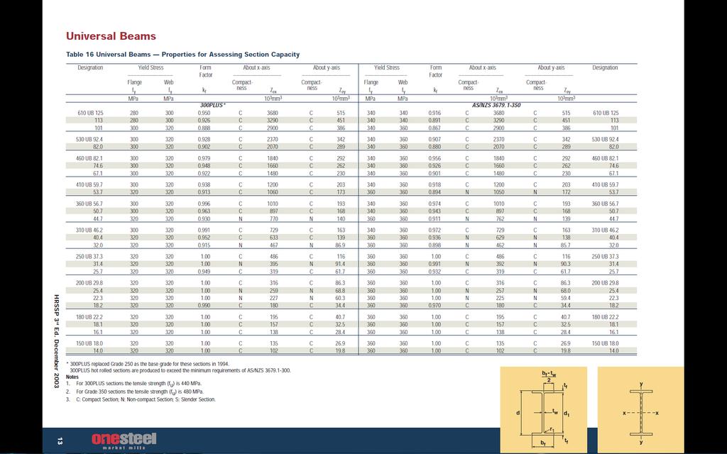
20 Assignment-II: BEAM ASSEMBLY - Use the standard dimensions from the catalogue provided. Here is how it is expected to look like. - You have to draw two universal beams and one square hollow section as shown below. - There are standard bolts, nuts and washers available in CATIA that are already drawn. You don t need to draw bolts, nuts and washers. During assembly you will bring them from CATIA library. 20
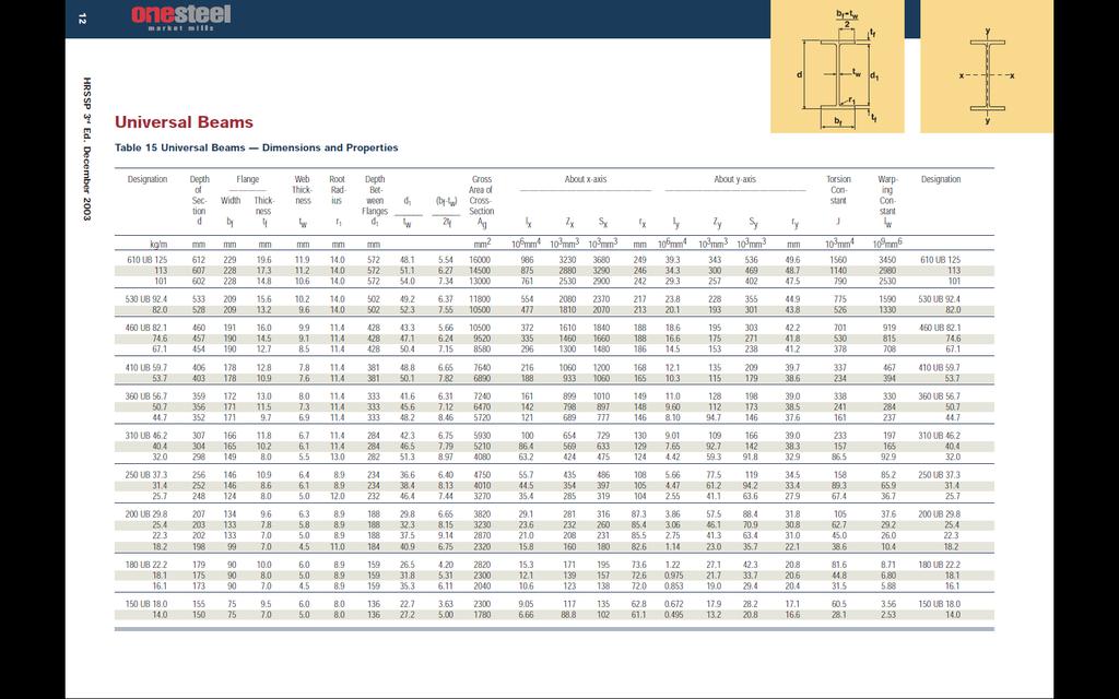
21 21
22 22

23 Square Hollow Sections 1 of 5 13/04/2011 7:56 AM Disclaimer: The information on this page has not been checked by an independent person. Use this information at your own risk. ROYMECH These Pages include various standards. To confirm the status of any standard, identify the replacement standard if it is obsolete and/or purchase the standard please use. BSI Shop It is also possible to become a BSI member and obtain copies of the Standards at much reduced prices. Home Steel Section Index Square Hollow Sections-Cold Formed..BS EN 10219:1997 Table of Dimensions + Properties Corner Radii Second Area of Radius of Section Plastic Torsional Constants Section Size Thick's Mass/m Moment of Section Gyration Modulus Modulus Surface Area Ext'l Int'l Area Inertia Modulus B T ro ri M/m A I r Z S J C As mm x mm mm mm mm kg/m cm 2 cm 4 cm cm 3 cm 3 cm 4 cm 3 m 2 /m
24 Square Hollow Sections 2 of 5 13/04/2011 7:56 AM
25 Square Hollow Sections 3 of 5 13/04/2011 7:56 AM
26 Square Hollow Sections 4 of 5 13/04/2011 7:56 AM
27 Square Hollow Sections 5 of 5 13/04/2011 7:56 AM Corner Radii Second Area of Radius of Section Plastic Torsional Constants Section Size Thick's Mass/m Moment of Section Gyration Modulus Modulus Surface Area Ext'l Int'l Area Inertia Modulus B T ro ri M/m A I r Z S J C As mm x mm mm mm mm kg/m cm 2 cm 4 cm cm 3 cm 3 cm 4 cm 3 m 2 /m Please Send Comments to Roy@roymech.co.uk Last Updated 04/04/2006 This Page is being developed Home Steel Section Index
28 Parallel Metric Keys and Keyway Dimensions Disclaimer: The information on this page has not been checked by an independent person. Use this information at your own risk. Click arrows to page adverts ROYMECH These Pages include various standards. To confirm the status of any standard, identify the replacement standard if it is obsolete and/or purchase the standard please use. BSI Shop It is also possible to become a BSI member and obtain copies of the Standards at much reduced prices. Home Keyways Index Keys and keyway Dimensions KeyWay /Key Dimensions keyways /keys dimension in accordance with BS :1972: Specification for metric keys and keyways - Parallel and taper keys Nominal Dia d Over Incl Key KeyWay Width b b x h width x thck Nom Depth Tolerance Class Shaft t 1 Hub t 2 Free Normal Close/Int Shaft H9 Hub D10 Shaft N9 Hub Js9 Shaft/Hub P9 Radius r Nom Tol Nom Tol Max min 6 8 2x2 2 +0,025 +0,06-0,004 +0,012-0,006 1,2 1,0 0,16 0, x ,02-0,029-0,012-0,031 1,8 1,4 0,16 0,08 +0,1 +0, x4 4 2,5 0 1,8 0 0,16 0,08 +0,03 +0, ,015-0, x5 5 3,0 2,3 0,25 0, ,030-0,030-0,015-0, x6 6 3,5 2,8 0,25 0, x7 8 +0,036 +0, ,018-0,015 4,0 +0,2 3,3 +0,2 0,25 0, x ,040-0,036-0,018-0,051 5,0 0 3,3 0 0,40 0, x8 12 5,0 3,3 0,40 0, x ,043 +0, ,021-0,018 5,5 3,8 0,40 0, x ,050-0,043-0,021-0,061 6,0 4,3 0,40 0, x ,0 4,4 0,40 0, x ,5 +0,2 +0,2 4, ,60 0, x ,052 +0, ,026-0,022 9,0 5,4 0,60 0, x ,065-0,052-0,026-0,074 9,0 5,4 0,60 0, x ,0 6,4 0,60 0, x ,0 7,4 0,6 0, x ,0 8,4 1,0 0,7 1:18:44 PM]
29 Parallel Metric Keys and Keyway Dimensions x ,062 +0, ,031-0, ,080-0,062-0,031-0,088 13,0 9,4 1,0 0, x ,0 10,4 1,0 0, x ,0 11,4 1,0 0, x ,0 +0,3 12,4 +0,3 1,6 1, x ,074 +0, ,037-0,032 20,0 0 12,4 0 1,6 1, x ,100-0,074-0,037-0,106 22,0 14,4 1,6 1, x ,0 15,4 2,5 2, x ,087 +0, ,043-0,037 28,0 17,4 2,5 2, x ,120-0,087-0,043-0,124 31, ,5 2,0 Key Dimensions Width b Thickness h Chamfer S Range Of Lengths Nom Tol(h9) Nom As indicated(h9/h11) Min Max From Inc 2 2 (h9) 0,16 0, , ,025 0,16 0, (h9) 0,16 0, ,25 0, , ,030 0,25 0, ,25 0, ,036 8 (h11) 0,40 0, ,40 0, ,090 0,40 0, , ,40 0, ,40 0, ,60 0, (h11) ,60 0, , ,110 0,60 0, ,60 0, ,60 0, ,00 1, (h11) 1,00 1, , ,130 1,00 1, ,00 1, ,60 2, ,60 2, , (h11) 1,60 2, ,160 2,50 3, ,50 3, , ,50 3, Standard keylengths (mm) :18:44 PM]
30 Parallel Metric Keys and Keyway Dimensions b>links Providing information on Keyways 1. Mitcalc.com...Excel based programme allowing detailed design of shaft connection (19 Eur) 2. Hercules -Keyways dimensions...download of keyway dimensions 3. Specifying Rectangular Keyways...MDmetric document - useful check information for my tables 4. Transeals - Keyways...Transeals - useful check information for my tables Send Comments to Roy Beardmore Last Updated 08/04/2012 This Page is being developed Home Keyways Index 1:18:44 PM]

31
Part Design Fundamentals
 Part Design Fundamentals 1 Course Presentation Objectives of the course In this course you will learn basic methods to create and modify solids features and parts Targeted audience New CATIA V5 Users 1
Introduction to CATIA V5
 Introduction to CATIA V5 Release 17 (A Hands-On Tutorial Approach) Kirstie Plantenberg University of Detroit Mercy SDC PUBLICATIONS Schroff Development Corporation www.schroff.com Better Textbooks. Lower
Basic Features. In this lesson you will learn how to create basic CATIA features. Lesson Contents: CATIA V5 Fundamentals- Lesson 3: Basic Features
 Basic Features In this lesson you will learn how to create basic CATIA features. Lesson Contents: Case Study: Basic Features Design Intent Stages in the Process Determine a Suitable Base Feature Create
Table of Contents. Dedication Preface. Chapter 1: Introduction to CATIA V5-6R2015. Chapter 2: Drawing Sketches in the Sketcher Workbench-I.
 Table of Contents Dedication Preface iii xvii Chapter 1: Introduction to CATIA V5-6R2015 Introduction to CATIA V5-6R2015 1-2 CATIA V5 Workbenches 1-2 System Requirements 1-4 Getting Started with CATIA
CATIA Instructor-led Live Online Training Program
 Course Outline Introduction & Understanding to CATIA Environment Introduction & Understanding to CATIA interface Starting new file Understand the Sketcher workbench of CATIA V5 Start a new file in the
Table of Contents. Lesson 1 Getting Started
 NX Lesson 1 Getting Started Pre-reqs/Technical Skills Basic computer use Expectations Read lesson material Implement steps in software while reading through lesson material Complete quiz on Blackboard
Using Siemens NX 11 Software. The connecting rod
 Using Siemens NX 11 Software The connecting rod Based on a Catia tutorial written by Loïc Stefanski. At the end of this manual, you should obtain the following part: 1 Introduction. Start NX 11 and open
Lesson 6 2D Sketch Panel Tools
 Lesson 6 2D Sketch Panel Tools Inventor s Sketch Tool Bar contains tools for creating the basic geometry to create features and parts. On the surface, the Geometry tools look fairly standard: line, circle,
SolidWorks 95 User s Guide
 SolidWorks 95 User s Guide Disclaimer: The following User Guide was extracted from SolidWorks 95 Help files and was not originally distributed in this format. All content 1995, SolidWorks Corporation Contents
Education Curriculum Combined Specialist
 Education Curriculum Combined Specialist Invest your time in imagining next generation designs. Here s what we will teach you to give shape to your imagination. CATIA Combined Specialist Course CATIA Mechanical
NX 7.5. Table of Contents. Lesson 3 More Features
 NX 7.5 Lesson 3 More Features Pre-reqs/Technical Skills Basic computer use Completion of NX 7.5 Lessons 1&2 Expectations Read lesson material Implement steps in software while reading through lesson material
Chapter 2. Drawing Sketches for Solid Models. Learning Objectives
 Chapter 2 Drawing Sketches for Solid Models Learning Objectives After completing this chapter, you will be able to: Start a new template file to draw sketches. Set up the sketching environment. Use various
CATIA V5 Workbook Release V5-6R2013
 CATIA V5 Workbook Release V5-6R2013 Richard Cozzens SDC PUBLICATIONS Better Textbooks. Lower Prices. www.sdcpublications.com Powered by TCPDF (www.tcpdf.org) Visit the following websites to learn more
SolidWorks Part I - Basic Tools SDC. Includes. Parts, Assemblies and Drawings. Paul Tran CSWE, CSWI
 SolidWorks 2015 Part I - Basic Tools Includes CSWA Preparation Material Parts, Assemblies and Drawings Paul Tran CSWE, CSWI SDC PUBLICATIONS Better Textbooks. Lower Prices. www.sdcpublications.com Powered
AEROPLANE. Create a New Folder in your chosen location called Aeroplane. The four parts that make up the project will be saved here.
 AEROPLANE Prerequisite Knowledge Previous knowledge of the following commands is required to complete this lesson. Sketching (Line, Rectangle, Arc, Add Relations, Dimensioning), Extrude, Assemblies and
Introduction to Autodesk Inventor for F1 in Schools (Australian Version)
") Introduction to Autodesk Inventor for F1 in Schools (Australian Version) F1 in Schools race car In this course you will be introduced to Autodesk Inventor, which is the centerpiece of Autodesk s Digital
Introduction to Autodesk Inventor for F1 in Schools (Australian Version) F1 in Schools race car In this course you will be introduced to Autodesk Inventor, which is the centerpiece of Autodesk s Digital
Wireless Mouse Surfaces
 Wireless Mouse Surfaces Design & Communication Graphics Table of Contents Table of Contents... 1 Introduction 2 Mouse Body. 3 Edge Cut.12 Centre Cut....14 Wheel Opening.. 15 Wheel Location.. 16 Laser..
1. Create a 2D sketch 2. Create geometry in a sketch 3. Use constraints to position geometry 4. Use dimensions to set the size of geometry
 2.1: Sketching Many features that you create in Fusion 360 start with a 2D sketch. In order to create intelligent and predictable designs, a good understanding of how to create sketches and how to apply
Siemens NX11 tutorials. The angled part
 Siemens NX11 tutorials The angled part Adaptation to NX 11 from notes from a seminar Drive-to-trial organized by IBM and GDTech. This tutorial will help you design the mechanical presented in the figure
Graz University of Technology CATIA V5. Basic Training. CAx in Automotive and Engine Technology Dipl.-Ing. Dr.techn.
 CATIA V5 Basic Training CAx in Automotive and Engine Technology 313.067 Dipl.-Ing. Dr.techn. Michael Lang Preface The present script includes an introduction of the main features in the 3D design software
Beginner s Guide to SolidWorks Alejandro Reyes, MSME Certified SolidWorks Professional and Instructor SDC PUBLICATIONS
 Beginner s Guide to SolidWorks 2008 Alejandro Reyes, MSME Certified SolidWorks Professional and Instructor SDC PUBLICATIONS Schroff Development Corporation www.schroff.com www.schroff-europe.com Part Modeling
Engineering Technology
 Engineering Technology Introduction to Parametric Modelling Engineering Technology 1 See Saw Exercise Part 1 Base Commands used New Part This lesson includes Sketching, Extruded Boss/Base, Hole Wizard,
< Then click on this icon on the vertical tool bar that pops up on the left side.
 Pipe Cavity Tutorial Introduction The CADMAX Solid Master Tutorial is a great way to learn about the benefits of feature-based parametric solid modeling with CADMAX. We have assembled several typical parts
CAD-CAM-CAE Examples
 CAD-CAM-CAE Examples example title: example number: example level: CAx system: Related material part with TÁMOP Job Description: Shaft type component (CAD) ÓE-A06a basic - medium - advanced CATIA v5 CAD
Introduction to Circular Pattern Flower Pot
 Prerequisite Knowledge Previous knowledge of the sketching commands Line, Circle, Add Relations, Smart Dimension is required to complete this lesson. Previous examples of Revolved Boss/Base, Cut Extrude,
with Creo Parametric 4.0
 Parametric Modeling with Creo Parametric 4.0 An Introduction to Creo Parametric 4.0 NEW Contains a new chapter on 3D Printing Randy H. Shih SDC PUBLICATIONS Better Textbooks. Lower Prices. www.sdcpublications.com
CREO.1 MODELING A BELT WHEEL
 CREO.1 MODELING A BELT WHEEL Figure 1: A belt wheel modeled in this exercise. Learning Targets In this exercise you will learn: Using symmetry when sketching Using pattern to copy features Using RMB when
Introducing SolidWorks
 Introducing SolidWorks SAAST Robotics 2008 SolidWorks Software Visually-based 3-D Mechanical design software Engineers and Designers use it to: Quickly sketch out ideas Experiment with features, dimensions
ME Week 2 Project 2 Flange Manifold Part
 1 Project 2 - Flange Manifold Part 1.1 Instructions This project focuses on additional sketching methods and sketching commands. Revolve and Work features are also introduced. The part being modeled is
M TE S Y S LT U A S S A
 Dress-Up Features In this lesson you will learn how to place dress-up features on parts. Lesson Contents: Case Study: Timing Chain Cover Design Intent Stages in the Process Apply a Draft Create a Stiffener
Part 8: The Front Cover
 Part 8: The Front Cover 4 Earpiece cuts and housing Lens cut and housing Microphone cut and housing The front cover is similar to the back cover in that it is a shelled protrusion with screw posts extruding
Generative Drafting (ISO)
") CATIA Training Foils Generative Drafting (ISO) Version 5 Release 8 January 2002 EDU-CAT-E-GDRI-FF-V5R8 1 Table of Contents (1/2) 1. Introduction to Generative Drafting Generative Drafting Workbench Presentation
CATIA Training Foils Generative Drafting (ISO) Version 5 Release 8 January 2002 EDU-CAT-E-GDRI-FF-V5R8 1 Table of Contents (1/2) 1. Introduction to Generative Drafting Generative Drafting Workbench Presentation
Part Design. Sketcher - Basic 1 13,0600,1488,1586(SP6)
") Part Design Sketcher - Basic 1 13,0600,1488,1586(SP6) In this exercise, we will learn the foundation of the Sketcher and its basic functions. The Sketcher is a tool used to create two-dimensional (2D)
Part Design Sketcher - Basic 1 13,0600,1488,1586(SP6) In this exercise, we will learn the foundation of the Sketcher and its basic functions. The Sketcher is a tool used to create two-dimensional (2D)
From the above fig. After sketching the path and profile select the sweep command First select the profile from property manager tree And then select
 Chapter 5 In sweep command there is a) Two sketch profiles b) Two path c) One sketch profile and one path The sweep profile is used to create threads springs circular things and difficult geometry. For
Getting Started. Before You Begin, make sure you customized the following settings:
 Getting Started Getting Started Before getting into the detailed instructions for using Generative Drafting, the following tutorial aims at giving you a feel of what you can do with the product. It provides
AutoCAD Tutorial First Level. 2D Fundamentals. Randy H. Shih SDC. Better Textbooks. Lower Prices.
 AutoCAD 2018 Tutorial First Level 2D Fundamentals Randy H. Shih SDC PUBLICATIONS Better Textbooks. Lower Prices. www.sdcpublications.com Powered by TCPDF (www.tcpdf.org) Visit the following websites to
Designing in Context. In this lesson, you will learn how to create contextual parts driven by the skeleton method.
 Designing in Context In this lesson, you will learn how to create contextual parts driven by the skeleton method. Lesson Contents: Case Study: Designing in context Design Intent Stages in the Process Clarify
The Revolve Feature and Assembly Modeling
 The Revolve Feature and Assembly Modeling PTC Clock Page 52 PTC Contents Introduction... 54 The Revolve Feature... 55 Creating a revolved feature...57 Creating face details... 58 Using Text... 61 Assembling
1.6.7 Add Arc Length Dimension Modify Dimension Value Check the Sketch Curve Connectivity
 Contents 2D Sketch... 1 1.1 2D Sketch Introduction... 1 1.1.1 2D Sketch... 1 1.1.2 Basic Setting of 2D Sketch... 2 1.1.3 Exit 2D Sketch... 4 1.2 Draw Common Geometry... 5 2.2.1 Points... 5 2.2.2 Lines
Feature-Based Modeling and Optional Advanced Modeling. ENGR 1182 SolidWorks 05
 Feature-Based Modeling and Optional Advanced Modeling ENGR 1182 SolidWorks 05 Today s Objectives Feature-Based Modeling (comprised of 2 sections as shown below) 1. Breaking it down into features Creating
Alternatively, the solid section can be made with open line sketch and adding thickness by Thicken Sketch.
 Sketcher All feature creation begins with two-dimensional drawing in the sketcher and then adding the third dimension in some way. The sketcher has many menus to help create various types of sketches.
Generative Drafting Overview What's New Getting Started User Tasks
 Generative Drafting Overview Conventions What's New Getting Started Defining the Drawing Sheet Part Drawing Opening a Part Creating a Front View Creating a Projection View Creating a Section View Creating
Explanation of buttons used for sketching in Unigraphics
 Explanation of buttons used for sketching in Unigraphics Sketcher Tool Bar Finish Sketch is for exiting the Sketcher Task Environment. Sketch Name is the name of the current active sketch. You can also
Inventor-Parts-Tutorial By: Dor Ashur
 Inventor-Parts-Tutorial By: Dor Ashur For Assignment: http://www.maelabs.ucsd.edu/mae3/assignments/cad/inventor_parts.pdf Open Autodesk Inventor: Start-> All Programs -> Autodesk -> Autodesk Inventor 2010
Creo Parametric 2.0: Introduction to Solid Modeling. Creo Parametric 2.0: Introduction to Solid Modeling
 Creo Parametric 2.0: Introduction to Solid Modeling 1 2 Part 1 Class Files... xiii Chapter 1 Introduction to Creo Parametric... 1-1 1.1 Solid Modeling... 1-4 1.2 Creo Parametric Fundamentals... 1-6 Feature-Based...
Toothbrush Holder. A drawing of the sheet metal part will also be created.
 Prerequisite Knowledge Previous knowledge of the following commands is required to complete this lesson; Sketch (Line, Centerline, Circle, Add Relations, Smart Dimension,), Extrude Boss/Base, and Edit
SOLIDWORKS 2015 and Engineering Graphics
 SOLIDWORKS 2015 and Engineering Graphics An Integrated Approach Randy H. Shih SDC PUBLICATIONS Better Textbooks. Lower Prices. www.sdcpublications.com Powered by TCPDF (www.tcpdf.org) Visit the following
MN Modelling Objects and Creating Manufacturing Strategy
 Abstract This document and the accompanying files describe the process of modelling a bell housing jig using the 3D software Catia V5. The manufacturing process by which the bell housing would be created
1. Open the Feature Modeling demo part file on the EEIC website. Ask student about which constraints needed to Fully Define.
 BLUE boxed notes are intended as aids to the lecturer RED boxed notes are comments that the lecturer could make Control + Click HERE to view enlarged IMAGE and Construction Strategy he following set of
Engineering & Computer Graphics Workbook Using SolidWorks 2014
 Engineering & Computer Graphics Workbook Using SolidWorks 2014 Ronald E. Barr Thomas J. Krueger Davor Juricic SDC PUBLICATIONS Better Textbooks. Lower Prices. www.sdcpublications.com Powered by TCPDF (www.tcpdf.org)
with MultiMedia CD Randy H. Shih Jack Zecher SDC PUBLICATIONS Schroff Development Corporation
 with MultiMedia CD Randy H. Shih Jack Zecher SDC PUBLICATIONS Schroff Development Corporation WWW.SCHROFF.COM Lesson 1 Geometric Construction Basics AutoCAD LT 2002 Tutorial 1-1 1-2 AutoCAD LT 2002 Tutorial
Module 2.1, 2.2 Review. EF101 Analysis & Skills Module 2.3. Sketched Features and Operations. On-line Help Two Locations
 EF101 Analysis & Skills Module 2.3 Engineering Graphics Revolved Features Placed Features Work Features Module 2.1, 2.2 Review What are the three types of operations for adding features to the base feature?
Conquering the Rubicon
 Autodesk Inventor R10 Fundamentals: Conquering the Rubicon Elise Moss SDC PUBLICATIONS Schroff Development Corporation www.schroff.com www.schroff-europe.com Schroff Development Corporation P.O. Box 1334
Alibre Design Tutorial: Loft, Extrude, & Revolve Cut Loft-Tube-1
 Alibre Design Tutorial: Loft, Extrude, & Revolve Cut Loft-Tube-1 Part Tutorial Exercise 5: Loft-Tube-1 [Complete] In this Exercise, We will set System Parameters first, then part options. Then, in sketch
AutoCAD LT 2012 Tutorial. Randy H. Shih Oregon Institute of Technology SDC PUBLICATIONS. Schroff Development Corporation
 AutoCAD LT 2012 Tutorial Randy H. Shih Oregon Institute of Technology SDC PUBLICATIONS www.sdcpublications.com Schroff Development Corporation AutoCAD LT 2012 Tutorial 1-1 Lesson 1 Geometric Construction
Training Guide Basics
 Training Guide Basics 2014, Missler Software. 7, Rue du Bois Sauvage F-91055 Evry, FRANCE Web: www.topsolid.com E-mail: info@topsolid.com All rights reserved. TopSolid Design Basics This information is
FUSION 360: SKETCHING FOR MAKERS
 FUSION 360: SKETCHING FOR MAKERS LaDeana Dockery 2017 MAKEICT Wichita, KS 1 Table of Contents Interface... 1 File Operations... 1 Opening Existing Models... 1 Mouse Navigation... 1 Preferences... 2 Navigation
Quasi-static Contact Mechanics Problem
 Type of solver: ABAQUS CAE/Standard Quasi-static Contact Mechanics Problem Adapted from: ABAQUS v6.8 Online Documentation, Getting Started with ABAQUS: Interactive Edition C.1 Overview During the tutorial
Digital Camera Exercise
 Commands Used New Part This lesson includes Sketching, Extruded Boss/Base, Extruded Cut, Fillet, Chamfer and Text. Click File, New on the standard toolbar. Select Part from the New SolidWorks Document
Below are the desired outcomes and usage competencies based on the completion of Project 4.
 Engineering Design with SolidWorks Project 4 Below are the desired outcomes and usage competencies based on the completion of Project 4. Project Desired Outcomes: An understanding of the customer s requirements
Parametric Modeling with Creo Parametric 2.0
 Parametric Modeling with Creo Parametric 2.0 An Introduction to Creo Parametric 2.0 Randy H. Shih SDC PUBLICATIONS Schroff Development Corporation Better Textbooks. Lower Prices. www.sdcpublications.com
and Engineering Graphics
 SOLIDWORKS 2018 and Engineering Graphics An Integrated Approach Randy H. Shih SDC PUBLICATIONS Better Textbooks. Lower Prices. www.sdcpublications.com Powered by TCPDF (www.tcpdf.org) Visit the following
for Solidworks TRAINING GUIDE LESSON-9-CAD
 for Solidworks TRAINING GUIDE LESSON-9-CAD Mastercam for SolidWorks Training Guide Objectives You will create the geometry for SolidWorks-Lesson-9 using SolidWorks 3D CAD software. You will be working
IDEA Connections. User guide
 IDEA Connections user guide IDEA Connections User guide IDEA Connections user guide Content 1.1 Program requirements... 4 1.1 Installation guidelines... 4 2 User interface... 5 2.1 3D view in the main
Evaluation Chapter by CADArtifex
 The premium provider of learning products and solutions www.cadartifex.com EVALUATION CHAPTER 2 Drawing Sketches with SOLIDWORKS In this chapter: Invoking the Part Modeling Environment Invoking the Sketching
Engineering & Computer Graphics Workbook Using SOLIDWORKS
 Engineering & Computer Graphics Workbook Using SOLIDWORKS 2017 Ronald E. Barr Thomas J. Krueger Davor Juricic SDC PUBLICATIONS Better Textbooks. Lower Prices. www.sdcpublications.com Powered by TCPDF (www.tcpdf.org)
CATIA-5 PART-B: 3D CAD, Mechanisms and Finite Element Analysis
 PDHonline Course G351 (10 PDH) CATIA-5 PART-B: 3D CAD, Mechanisms and Finite Element Analysis Instructor: John R. Andrew, P.E. 2012 PDH Online PDH Center 5272 Meadow Estates Drive Fairfax, VA 22030-6658
Modeling Basic Mechanical Components #1 Tie-Wrap Clip
 Modeling Basic Mechanical Components #1 Tie-Wrap Clip This tutorial is about modeling simple and basic mechanical components with 3D Mechanical CAD programs, specifically one called Alibre Xpress, a freely
SDC. AutoCAD LT 2007 Tutorial. Randy H. Shih. Schroff Development Corporation Oregon Institute of Technology
 AutoCAD LT 2007 Tutorial Randy H. Shih Oregon Institute of Technology SDC PUBLICATIONS Schroff Development Corporation www.schroff.com www.schroff-europe.com AutoCAD LT 2007 Tutorial 1-1 Lesson 1 Geometric
Activity 1 Modeling a Plastic Part
 Activity 1 Modeling a Plastic Part In this activity, you will model a plastic part. When completed, your plastic part should look like the following two illustrations. While building this model, take time
SDC. SolidWorks Tutorial 2001Plus. A Competency Project Based Approach Utilizing 3D Solid Modeling. David C. Planchard & Marie P.
 2001Plus A Competency Project Based Approach Utilizing 3D Solid Modeling David C. Planchard & Marie P. Planchard SDC PUBLICATIONS www.schroff.com www.schroff-europe.com Project 2 Below are the desired
1 Sketching. Introduction
 1 Sketching Introduction Sketching is arguably one of the more difficult techniques to master in NX, but it is well-worth the effort. A single sketch can capture a tremendous amount of design intent, and
Inventor Activity 5: Lofted Vase
 Inventor Activity 5: Lofted Vase In this tutorial, you will use a few new commands to create a free form Lofted object. Sometimes you want to create an object that is not made up of square, flat, or perfectly
AutoCAD LT 2009 Tutorial
 AutoCAD LT 2009 Tutorial Randy H. Shih Oregon Institute of Technology SDC PUBLICATIONS Schroff Development Corporation www.schroff.com Better Textbooks. Lower Prices. AutoCAD LT 2009 Tutorial 1-1 Lesson
IDEA Connection 8. User guide. IDEA Connection user guide
 IDEA Connection user guide IDEA Connection 8 User guide IDEA Connection user guide Content 1.1 Program requirements... 5 1.2 Installation guidelines... 5 2 User interface... 6 2.1 3D view in the main window...
Shaft Hanger - SolidWorks
 ME-430 INTRODUCTION TO COMPUTER AIDED DESIGN Shaft Hanger - SolidWorks BY: DR. HERLI SURJANHATA ASSIGNMENT Submit TWO isometric views of the Shaft Hanger with your report, 1. Shaded view of the trimetric
SolidWorks 2005 Tutorial. and MultiMedia CD. A Step-by-step Project Based Approach Utilizing 3D Solid Modeling
 INSIDE: MultiMedia CD An audio/visual presentation of the tutorial projects SolidWorks 2005 Tutorial and MultiMedia CD A Step-by-step Project Based Approach Utilizing 3D Solid Modeling David C. Planchard
DUE DATE: Friday 4/6/2018 at 3:30 PM
 MECH 130 SPRING 2018 CAD LAB 4 FINAL REVISION HARDCOPIES NEEDED DUE DATE: Friday 4/6/2018 at 3:30 PM After the revised hitch, the ball and the pin parts were created from the Handout call LAB4 PART Creation,
AutoCAD 2018 Fundamentals
 Autodesk AutoCAD 2018 Fundamentals Elise Moss SDC PUBLICATIONS Better Textbooks. Lower Prices. www.sdcpublications.com Powered by TCPDF (www.tcpdf.org) Visit the following websites to learn more about
Prismatic Machining Preparation Assistant
 Prismatic Machining Preparation Assistant Overview Conventions What's New Getting Started Open the Design Part and Start the Workbench Automatically Create All Machinable Features Open the Manufacturing
Getting Started. Chapter. Objectives
 Chapter 1 Getting Started Autodesk Inventor has a context-sensitive user interface that provides you with the tools relevant to the tasks being performed. A comprehensive online help and tutorial system
Introduction to Autodesk Inventor User Interface Student Manual MODEL WINDOW
 Emmett Wemp EDTECH 503 Introduction to Autodesk Inventor User Interface Fill in the blanks of the different tools available in the user interface of Autodesk Inventor as your instructor discusses them.
Lesson 4 Extrusions OBJECTIVES. Extrusions
 Lesson 4 Extrusions Figure 4.1 Clamp OBJECTIVES Create a feature using an Extruded protrusion Understand Setup and Environment settings Define and set a Material type Create and use Datum features Sketch
An Introduction to Autodesk Inventor 2011 and AutoCAD Randy H. Shih SDC PUBLICATIONS. Schroff Development Corporation
 An Introduction to Autodesk Inventor 2011 and AutoCAD 2011 Randy H. Shih SDC PUBLICATIONS www.sdcpublications.com Schroff Development Corporation An Introduction to Autodesk Inventor 2011 and AutoCAD 2011
V4 Integration. CATIA V5 Training Exercises. V4 Integration. Version 5 Release 19 January 2009 EDU_CAT_EN_V4I_FX_V5R19. Copyright DASSAULT SYSTEMES 1
 CATIA V5 Training Exercises V4 Integration Version 5 Release 19 January 2009 EDU_CAT_EN_V4I_FX_V5R19 1 Table of Contents (1/2) Recap Exercise 1 4 Design Intent 5 Design Process 6 Step 1: Open a V4 Model
AutoCAD Inventor - Solid Modeling, Stress and Dynamic Analysis
 PDHonline Course G280 (15 PDH) AutoCAD Inventor - Solid Modeling, Stress and Dynamic Analysis Instructor: John R. Andrew, P.E. 2012 PDH Online PDH Center 5272 Meadow Estates Drive Fairfax, VA 22030-6658
IDEA Connection 8. User guide. IDEA Connection user guide
 IDEA Connection user guide IDEA Connection 8 User guide IDEA Connection user guide Content 1.1 Program requirements... 5 1.2 Installation guidelines... 5 2 User interface... 6 2.1 3D view in the main window...
Teach Yourself UG NX Step-by-Step
 Teach Yourself UG NX Step-by-Step By Hui Zhang Ph.D., P.Eng. www.geocities.com/zhanghui1998 Table of Contents Chapter 1 Introduction... 1 1.1 UG NX User Interface... 1 1.2 Solid Modeling Fundamentals...
5 More Than Straight Lines
 5 We have drawn lines, shapes, even a circle or two, but we need more element types to create designs efficiently. A 2D design is a flat representation of what are generally 3D objects, represented basically
Hydro Hull. Chapter 21. Boat. A. Save as "HYDRO". Step 1. Open your HULL MID PLANE file (Chapter 2).
.") Chapter 21 Boat Hydro Hull A. Save as "HYDRO". Step 1. Open your HULL MID PLANE file (Chapter 2). Step 2. Click File Menu > Save As. Step 3. Key-in HYDRO for the filename and press ENTER. B. Delete Loft1,
Chapter 21 Boat Hydro Hull A. Save as "HYDRO". Step 1. Open your HULL MID PLANE file (Chapter 2). Step 2. Click File Menu > Save As. Step 3. Key-in HYDRO for the filename and press ENTER. B. Delete Loft1,
Architecture 2012 Fundamentals
 Autodesk Revit Architecture 2012 Fundamentals Supplemental Files SDC PUBLICATIONS Schroff Development Corporation Better Textbooks. Lower Prices. www.sdcpublications.com Tutorial files on enclosed CD Visit
Nut and Bolt Tutorial
 Thread Representations Nut and Bolt Tutorial Parts to a Thread Thread Dimensioning Major Diameter Thread Series (IE UNC, UNF, ACME, etc) ½ - 13 UNC 2 A or B A = External B = Internal Threads per Inch Class
Lesson 4 Holes and Rounds
 Lesson 4 Holes and Rounds 111 Figure 4.1 Breaker OBJECTIVES Sketch arcs in sections Create a straight hole through a part Complete a Sketched hole Understand the Hole Tool Use Info to extract information
Software Development & Education Center NX 8.5 (CAD CAM CAE)
") Software Development & Education Center NX 8.5 (CAD CAM CAE) Detailed Curriculum Overview Intended Audience Course Objectives Prerequisites How to Use This Course Class Standards Part File Naming Seed
Software Development & Education Center NX 8.5 (CAD CAM CAE) Detailed Curriculum Overview Intended Audience Course Objectives Prerequisites How to Use This Course Class Standards Part File Naming Seed
Made Easy. Jason Pancoast Engineering Manager
 3D Sketching Made Easy Jason Pancoast Engineering Manager Today I have taught you to sketch in 3D. It s as easy as counting ONE, TWO, FIVE...er...THREE! When your sketch only lives in Y and in X, Adding
Tools for Design. with VEX Robot Kit: Randy H. Shih Oregon Institute of Technology SDC PUBLICATIONS
 Tools for Design with VEX Robot Kit: AutoCAD 2011 and Autodesk Inventor 2011 2D Drawing 3D Modeling Hand Sketching Randy H. Shih Oregon Institute of Technology INSIDE: SUPPLEMENTAL FILES ON CD SDC PUBLICATIONS
Product Modelling in Solid Works
 Product Modelling in Solid Works In the following exercise you will use solid works to construct the computer mouse shown opposite. In this exercise you will use a number of advanced features to achieve
Chapter 1. Creating, Profiling, Constraining, and Dimensioning the Basic Sketch. Learning Objectives. Commands Covered
 Chapter 1 Creating, Profiling, Constraining, and Dimensioning the Basic Sketch Learning Objectives After completing this chapter, you will be able to: Draw the basic outline (sketch) of designer model.