Project 8.1a Model A Button Maker
|
|
|
- Jonas Oswin Johnston
- 5 years ago
- Views:
Transcription


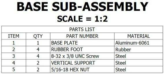
1 Page 1 of 16 Project 8.1a Model A Button Maker Introduction Interpreting dimensioned drawings is an important engineering skill. Using drawings to create a computer model of a part is also important. You learned earlier in this course that a sketch is the documentation foundation for related technical work. Communicating this information effectively allows a group of people to function as a design team. In this project you will further develop your modeling skills and your ability to use a computer as an efficient communication tool. The skills that you learned earlier in this course will be systematically applied to model the eight remaining parts needed for the Button Maker Assembly. The parts with the dimensions are listed below. Equipment Computer with 3D CAD solid modeling program Engineering notebook CAD Files (Teacher will provide as applicable)
2 Page 2 of 16 Procedure 1. Model and assemble the parts and subassemblies shown using the drawings provided. Sub Assembly Bottom Press Assembly Base Sub- Assembly A Lower Die Sub-Assembly B Handle Sub- Assembly C Upper Die Sub-Assembly D Item PART NUMBER Required Optional Assemble 1 BASE BEARING Model 2 1/4 20 CAP NUT Model 3 SMALL SNAP RING Model 4 HANDLE PIVOT PIN Model A BASE SUB-ASSEMBLY A Assemble B LOWER DIE SUB-ASSEMBLY B Assemble C HANDLE SUB-ASSEMBLY C Assemble D UPPER DIE SUB-ASSEMBLY D Assemble Assemble 1 BASE PLATE Model 2 RUBBER FOOT Model X 3/8 UNC SCREW Model 4 VERTICAL SUPPORT Model 5 5/16-18 HEX NUT Model 5 5/16-18 X 9/16 BUTTON CAP SCREW Model 6 RUBBER HANDLE SLEEVE Model 7 METAL HANDLE INSERT Model 8 7/16-14 X 1 3/8 SOCKET SET SCREW Model Assemble 1 BOTTOM DIE PLATE Model 2 5/16-18 HEX NUT Model 3 SEQUENCE LEVER ARM Model 4 ¼ WASHER Model 5 ¼-20 X 5/16 BUTTON CAP SCREW Model 6 LOWER DIE 1 OUTER RING Model 7 LOWER DIE 1 CENTER Model 8 ¼-20 X ¾ SOCKET HEAD SCREW Model 9 LOWER DIE 2 CENTER Model 10 LOWER DIE 2 OUTER RING Model 11 LOWER DIE 2 SPACER Model 12 BOTTOM DIE SPRING Model Assemble 1 HANDLE BODY Model 2 ROLLER SPACER Model 3 ROLLER INNER BEARING Model 4 ROLLER OUTER BEARING Model Assemble 1 UPPER DIE CENTER SUPPORT Model 2 LARGE SNAP RING Model 3 HANDLE RETENTION PIN Model 4 UPPER DIE CENTER PIN Model 5 UPPER DIE SPRING Model 6 UPPER OUTER RING Model 7 UPPER DIE PRESSURE RING Model 8 #8-32 X 0.7 SCREW Model 9 UPPER DIE CENTER Model 10 ¼-20 X 1 3/16 SOCKET HEAD SCREW Model
3 Page 3 of 16


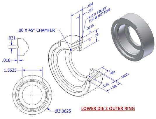
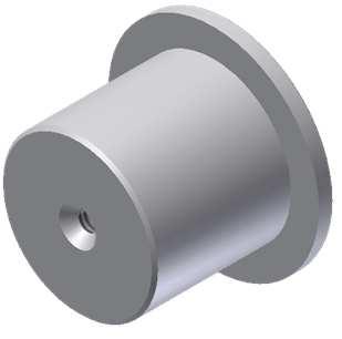
4 Page 4 of 16 Button Press Tolerances All parts have the following tolerances: X.X = +/-.020 X.XX = +/-.010 X.XXX = +/ Model and assemble this subassembly shown using the drawings provided.


5 Page 5 of 16

6 Page 6 of 16


7 Page 7 of Model and assemble this subassembly shown using the drawings provided.

8 Page 8 of 16
9 Page 9 of Model and assemble this subassembly shown using the drawings provided.

10 Page 10 of 16


11 Page 11 of 16
12 Page 12 of Model and assemble this subassembly shown using the drawings provided.

13 Page 13 of 16

14 Page 14 of 16
15 Page 15 of 16
16 Page 16 of 16 Conclusion 1. Why are drawings composed of different line conventions? 2. What is the purpose of a sectional view? 3. What is the purpose of an auxiliary view? 4. Why are symbols used instead of words to identify hole types? 5. What is the format for calling out a tapped hole? 6. What advantage is there to using algebraic equations instead of numerical values when defining the dimensions of a CAD model? 7. What three types of constraints can be applied to CAD sketches or models? 8. How would a consumer most likely come into contact with an assembly view drawing? 9. What advantages do CAD drawings have over paper sketches?
Project 8.1b Model An Arbor Press
 Page 1 of 8 Project 8.1b Model An Arbor Press Introduction Have you ever done a skateboard trick or strapped on a pair of in-line skates? What is used between the wheels and axles to allow the wheels to
Section E SWEEP WAGON
 Section E SWEEP WAGON 1E 2E Index No. Part No. Description 1. 47-042058-002 Sweep Wagon Frame with Leaf Springs N.A. Sweep Wagon Frame without Leaf Springs 2. 47-041769-003 Sweep Board Only (brown for
Model No: TC10. Parts Information: Tyre Changer - Automatic
 Page 1 of 11 1 TC10.01 BODY 2 TC10.02 COLUMN 3 TC10.03 HORIZONTAL ARM ASS'Y 4 TC10.04 WASHER 5 TC10.05 RUBBER FOOT 6 TC10.06 COVER 7 TC10.07 SCREW M14x42 8 TC10.08 PRESS COVER 9 TC10.09 STOP-UP 10 TC10.10
HD38, HD58, HD78 REV
 HD38, HD58, HD78 REV. 07.29.2014 COVER for HD38, HD58, HD78 5 P004868 1/4-20x3/4 Button Head Cap Screw Stainless Steel 2 6 P001450 Lockwasher - Internal Tooth.250 6 8 P005200 Wave Disc Washer 4 10 P004869
ELECTRIC TOOL PARTS LIST
 Hitachi Power Tools LIST E936 ELECTRIC TOOL PARTS LIST COMPOUND SAW Model 2004 4 20 (E1) 1 2 3 23 24 7 8 9 10 6 5 4 15 11 16 12 13 12 14 18 25 26 27 28 29 30 19 17 1 9 11 16 21 624 20 22 39 40 41 42 35
WELDING POSITIONER PARTS BREAKDOWN DRAWING GP-200
 WELDING POSITIONER PARTS BREAKDOWN 10 DRAWING GP-200 1 GP-200-001 FRAME 1 2 GK-160-012 5/16"-18UNC x 5/8" CARRIAGE BOLT 6 3 GK-136-055 5/16"Ø LOCK WASHER 6 4 GK-109-052 5/16"-18UNC HEX NUT 10 5 GP-200-002
Orbital Test Stand. Operations and Assembly Manual. Department of Mechanical Engineering Northern Arizona University Flagstaff, AZ 86011
 Orbital Test Stand Operations and Assembly Manual Department of Mechanical Engineering Northern Arizona University Flagstaff, AZ 86011 TABLE OF CONTENTS 1.0 Components List... 2 2.0 Assembly Instructions...
Parts Catalog. S-Series Slicer Manual Frozen Option S13. Model:
 , 07 995 ECN 08 Parts Catalog S S-Series Slicer Manual Frozen Option Model: S 05/0/07 Rev. G IMPORTANT! TO EXPEDITE SHIPMENT OF PARTS, ALWAYS SPECIFY MODEL, REV, PART NUMBER, AND SERIAL NUMBER OF UNIT.
RYOBI. 10 in. (254 mm) TABLE SAW MODEL NO. BTS15 REPAIR SHEET
 TABLE SAW MODEL NO. BTS15 REPAIR SHEET") RYOBI 0 in. ( mm) TABLE SAW MODEL NO. BTS REPAIR SHEET FIGURE A 0 0 0 0 The model number will be found on a plate attached to the motor housing. Always mention the model number in all correspondence regarding
RYOBI 0 in. ( mm) TABLE SAW MODEL NO. BTS REPAIR SHEET FIGURE A 0 0 0 0 The model number will be found on a plate attached to the motor housing. Always mention the model number in all correspondence regarding
SPARE PARTS LIST MODEL NO. LB1200F PAGE 1 ITEM PART NO. DESCRIPTION QTY NOTE
 PAGE 1 001 JM21000018 HEX.SOCKET HEAD SCREW M5X12 4 002 JM21000019 SPRING WASHER 5 4 003 JM21000020 FLAT WASHER 5 4 004 JM21000021 UP COVER COMPLETE 1 005 JM21000025 MICRO SWITCH FIX PANEL A 1 006 JM21000026
RYOBI 10 in. (254 mm) COMPOUND MITER SAW MODEL NO. TS1352 REPAIR SHEET
 COMPOUND MITER SAW MODEL NO. TS1352 REPAIR SHEET") RYOBI 0 in. (5 mm) COMPOUND MITER SAW MODEL NO. TS5 REPAIR SHEET FIGURE A 50 89 5 6 5 5 5 9 8 8 5 6 0 9 8 9 0 5 5 6 5 6 5 0 9 8 0 6 8 9 9 5 0 55 56 WARNING: Improper repair of a double insulated tool can
RYOBI 0 in. (5 mm) COMPOUND MITER SAW MODEL NO. TS5 REPAIR SHEET FIGURE A 50 89 5 6 5 5 5 9 8 8 5 6 0 9 8 9 0 5 5 6 5 6 5 0 9 8 0 6 8 9 9 5 0 55 56 WARNING: Improper repair of a double insulated tool can
 2705 03-09 99 98 97 82 88 89 83 84 85 86 87 101 103 100 106 81 71 105 104 73 74 75 76 77 78 80 79 57 62 58 56 63 65 66 67 68 64 69 70 59 60 61 31 30 29 32 34 35 41 40 42 36 37 38 39 43 4445 46 33 55 54
ORTOP Modular Robot v3.0 Arm Assembly
 Base Plate Assembly Parts Needed: Arm Assembly BAG 1 2 Socket Head Cap Screw, 1-1/4" 2 Socket Head Cap Screw, 1/2" 2 Button Head Cap Screw, 3/8" 6 Nuts 1 Gear Hub Spacer 1 Flat Building Plate 1 Single
351 DOOR CLOSER WITH DOUBLE LEVER ARM (OP) INSTALLATION INSTRUCTIONS
 INSTALLATION INSTRUCTIONS") 2 351 DOOR CLOSER WITH DOUBLE LEVER ARM (OP) INSTALLATION INSTRUCTIONS Strength Adjustable From Size 1 Thru 6 CAUTION: FAILURE TO INSTALL OR ADJUST PROPERLY MAY RESULT IN INJURY OR DAMAGE Auxiliary door
2 351 DOOR CLOSER WITH DOUBLE LEVER ARM (OP) INSTALLATION INSTRUCTIONS Strength Adjustable From Size 1 Thru 6 CAUTION: FAILURE TO INSTALL OR ADJUST PROPERLY MAY RESULT IN INJURY OR DAMAGE Auxiliary door
Arc Trainer Main Frame Assembly
 Arc Trainer Main Frame Assembly Kit No. 610AK019-4 Kit No. 630AK019-4 NOTE: This instruction sheet describes how to replace the main frame assembly in the Arc Trainer 610A. Tools Required 3/16 Allen wrench
Number Wheeler P/N Description Set Rex P/N Notes Base 1 J Support, Right 1 J Support, Left 1 J Nut (M8)
") 1 603500 Base 1 J001 2 603501 Support, Right 1 J002 3 603502 Support, Left 1 J003 4 600328 Nut (M8) 4 5 600130 Spring Washer (8mm) 4 6 600344 Roll Pin (M6x30) 4 7 600129 Socket Hd Cap Screw (M8x25) 4 8
1 603500 Base 1 J001 2 603501 Support, Right 1 J002 3 603502 Support, Left 1 J003 4 600328 Nut (M8) 4 5 600130 Spring Washer (8mm) 4 6 600344 Roll Pin (M6x30) 4 7 600129 Socket Hd Cap Screw (M8x25) 4 8
RYOBI 10 IN (254 MM) TABLE SAW MODEL NO. BT REPAIR SHEET
 TABLE SAW MODEL NO. BT REPAIR SHEET") RYOBI 0 IN (2 MM) TABLE SAW MODEL NO. BT00- REPAIR SHEET 2 RYOBI 0 in. (2 mm) TABLE SAW - MODEL NO. BT00- FOR MITER TABLE ASSEMBLY, REFER TO FIGURE B FOR BLADE GUARD ASSEMBLY, REFER TO FIGURE E FOR RIP
RYOBI 0 IN (2 MM) TABLE SAW MODEL NO. BT00- REPAIR SHEET 2 RYOBI 0 in. (2 mm) TABLE SAW - MODEL NO. BT00- FOR MITER TABLE ASSEMBLY, REFER TO FIGURE B FOR BLADE GUARD ASSEMBLY, REFER TO FIGURE E FOR RIP
Parts Catalog. S-Series Slicer Smart Manual SG13. Model:
 , 07 99507 ECN 065 Parts Catalog S-Series Slicer Smart Manual Model: SG SG 0/0/07 Rev. G IMPORTANT! TO EXPEDITE SHIPMENT OF PARTS, ALWAYS SPECIFY MODEL, REV, PART NUMBER, AND SERIAL NUMBER OF UNIT. GLOBE
Section D ACCELERATOR
 Section D ACCELERATOR 1D Index No. Part No. Description 1. 47-021476-001 Ball Accelerator Box 2. 11-051019-001 Hex Hd. Cap Screw (10 mm x 25 mm) 3. 11-052018-001 Flat Washer (10.5 mm x 21 mm x 2 mm) 4.
Strata. urniture. Adriana Instructions. Parts in the Arm Box: Parts in the Body Box: Watch our assembly videos at
 1A Watch our assembly videos at www.strataf.com/videos Parts in the Arm Box: Arm - Outside View Arm - Inside View 1B Parts in the Body Box: Back Deck x 1 Seat Deck x 1 with the Feet attached Back Panel
CATALOG OF REPLACEMENT PARTS
 CATALOG OF REPLACEMENT PARTS MODEL X13 SERIES SLICER FORM 43180 Rev. A (April 2013) F-43180 Rev. A (April 2013) - 2-2013 Table of Contents 5 ELECTRICAL COMPONENTS 7 RING GUARD AND CENTER PLATE 9 ARM ASSEMBLY
RYOBI 10 in. (254 mm) TABLE SAW MODEL NO. BT3100 REPAIR SHEET
 TABLE SAW MODEL NO. BT3100 REPAIR SHEET") RYOBI 0 in. (4 mm) TABLE SAW MODEL NO. BT00 REPAIR SHEET FOR MITER TABLE ASSEMBLY, REFER TO FIGURE B FOR BLADE GUARD ASSEMBLY, REFER TO FIGURE E FOR RIP FENCE ASSEMBLY, REFER TO FIGURE C FOR MOTOR ASSEMBLY,
RYOBI 0 in. (4 mm) TABLE SAW MODEL NO. BT00 REPAIR SHEET FOR MITER TABLE ASSEMBLY, REFER TO FIGURE B FOR BLADE GUARD ASSEMBLY, REFER TO FIGURE E FOR RIP FENCE ASSEMBLY, REFER TO FIGURE C FOR MOTOR ASSEMBLY,
EMS-2025scl 230v. Sliding Compound Mitre Saw Fig.1. Revision Date 26/01/2006
 Fig.1 Fig.2 701 inc 2,702,703,704 1 Base 93 089100102700 Space washer Base Assembly Parts (A) 30.23 94 Screw, for base, 45 152 Miter scale label, 2 089100102002 Rubber feet 0.10 702 Pivot Shaft & Screw
RYOBI 10 in. TABLE SAW - MODEL NO. BT3000
 FOR MITER TABLE ASSEMBLY, REFER TO FIGURE 0 RYOBI 0 in. TABLE SAW - MODEL NO. BT000 FIGURE 5: 0 in. TABLE SAW FOR BLADE GUARD ASSEMBLY, REFER TO FIGURE FOR RIP FENCE ASSEMBLY, REFER TO FIGURE FOR MOTOR
>> ACCESSORIES 5 2 METALPLAST-SOPRANA
 CABIN 7 >> ACCESSORIES METALPLAST-SOPRANA srl 10090 BRUINO TO VIA VOLVERA 88/4 TELEPHONE 011-9086490 FAX 011-9086979 E-MAIL : metsopr@tin.it WWW.metalplast-soprana.com 2 GRAB HANDLES GRAB HANDLE CODE 127013
Diesel Pile Hammer D30-32 Part # 66508
 Diesel Pile Hammer D30-32 Part # 66508 2 Diesel Pile Hammer D30-32 Part # 66508 Pos Order No Pg Description Qty 66508 Diesel Pile Hammer D30-32 cmpl 1 1 108742 4 Cylinder Lower Part cmpl 1 2 60151 Inner
SεW Supply, LLC 800B Parts List - OLD
 0 S040300 Thumb Screw 4-Set (Replacement for S-4-3) 1 D010000 Shot & Powder Tube Lids 2 TENG02000 Shot & Powder Plastic Tubes 12" 3 D03000 Shot & Powder Baffles 4 S040000 Shot & Powder Reservoir Plate
SPARE PARTS LIST MODEL NO PAGE 1 ITEM PART NO. DESCRIPTION QTY NOTE
 PAGE 1 001 342186-7 SWITCH PROTECTOR 1 002 911118-1 PAN HEAD SCREW M4X12 6 003 155512-9 SWITCH PLATE 1 004 651757-2 SWITCH ABK266 1 006 685712-2 SPONGE SHEET 60X60 1 007 911118-1 PAN HEAD SCREW M4X12 1
Diesel Hammer Model D19-42 Part #
 Diesel Hammer Model D19-42 Part # 120491 2 Diesel Pile Hammer Part # 120941 Pos Order No. Pg Description Qty 120941 Diesel Pile Hammer D19-42 (Bauer MNR:426514) 1 160198 4 Cylinder Lower Part cmpl 1 2
LISTA DE REFACCION MODELO LS1017L PAGINA 1. Pos. NUMERO DESCRIPCION Cant. NOTA
 PAGINA 1 001 JM23100006 CROSS HEAD SCREW M5X20 2 002 JM23100007 FLAT WASHER 5 2 003 JM23100008 PAD 4 004 JM23100009 LOCKNUT M10 1 005 JM23100010 FLAT WASHER 10 2 006 JM23100300 BASE COMPLETE 1 INC. 7 007
CATALOG OF REPLACEMENT PARTS
 The Choice of Experience CATALOG OF REPLACEMENT PARTS MODELS 909A 919A 909E 919E 909M 919M SLICERS EFFECTIVE MARCH 2009 - 2 - Table of Contents 5 ELECTRICAL COMPONENTS (909A & 919A) 7 ELECTRICAL COMPONENTS
SERVICE PARTS LIST PAGE 1 OF 6 BASE ASSEMBLY SPECIFY CATALOG NO. AND SERIAL NO. WHEN ORDERING PARTS 12" SLIDING COMPOUND MITER SAW
 PAGE 1 OF 6 BASE ASSEMBLY 00 0 CATALOG NO. EXAMPLE: SPECIFY CATALOG NO. AND NO. WHEN ORDERING PARTS 6955-20 1 02-80-0050 Thrust Bearing (1) 2 05-80-0510 M5 x 12mm Flat Head T-20 Screw (5) 3 05-81-0135
LISTA DE REFACCION MODELO LS1018L PAGINA 1. Pos. NUMERO DESCRIPCION Cant. NOTA
 PAGINA 1 001 JM23100006 CROSS HEAD SCREW M5X20 2 002 JM23100007 FLAT WASHER 5 2 003 JM23100008 PAD 4 004 JM23100009 LOCKNUT M10 1 005 JM23100010 FLAT WASHER 10 2 006 JM23100300 BASE COMPLETE 1 INC. 7 007
12. Mechanical Drawings & Parts Breakdown List
 12. Mechanical Drawings & Parts Breakdown List Note: When ordering parts, please be prepared with, 1. Machine model & serial number. 2. Item number. 3. Part number and description. 4. Year of Production.
Operating Instructions and Parts Manual 10-inch Table Saw
 Operating Instructions and Parts Manual 10-inch Table Saw Model 66 shown with optional extension table and legs, mobile base, and motor cover WMH TOOL GROUP 2420 Vantage Drive Elgin, Illinois 60123 Part
Copyright 2005 Valmont Industries, Inc.
 Hose Drag TOPIVIEW OF CART Universal 1 Left Guidance Support (4" H.D.) 1732080... Left Guidance Sumort.. 16". H.D.)... 1732138 2 Right Guidance Support (4" H.D.)... 1732081 Right Guidance Support (6" H.D.)...
535A. Main Components. Pipe and Bolt Threading Machine. Printed in U.S.A. Ridge Tool Company/Elyria, Ohio, U.S.A.
 Pipe and Bolt Threading Machine A Main Components 0 Screw, Button Head /" - 0 x /" () Washer, Flat /" ()" Top Cover 0 Base Bottom Cover Screw, Pan Head # - x " () Carriage Assembly 0 Front Support Bar
Section F SETTING TABLE
 Section F SETTING TABLE December 2009 1F Index No. Part No. Description 1. 47-051635-001 Geared Rack 2. 11-051880-001 N.A. Truss Hd. Machine Screw (6 mm x 16 mm) 47-861008-001 R.O. Truss Hd. Machine Screw
32 Gallon Perforated Square Receptacle
 32 Gallon Perforated Square Receptacle 992-031 24 5/" 24 5/" 39 1/2" 30 1/2" ITEM NO. PART NUMBER DESCRIPTION QTY. 1 653-006 Receptacle Base 1 2 653-045 32 Gallon Perforated Side 4 3 653-011 Arch Lid 1
MITCHELL WREATH RINGS NO-HAMMER ASSEMBLY INSTRUCTIONS
 MITCHELL WREATH RINGS NO-HAMMER ASSEMBLY INSTRUCTIONS METAL STAND WITH WOOD STAND WITH PAGE 2 OF 10 MASTER PARTS LIST HEAD ASSEMBLY LINKAGE ASSEMBLY HOOK LEVER ASSEMBLY FOOT PEDAL ASSEMBLY ALL FASTENERS
MODEL RA-200N RADIAL ARM SAW
 ITEM NO PART NO DESCRIPTION PRICE 1 6130089 HEX. NUT (L.H.T.) W5/8"-18UNF 2.18 2 6900079 CONICAL SPRING 16.3 X 31.5 X 1.2 0.78 3 6940444 OUTER FLANGE 4.49 4 6940443 INNER FLANGE 4.91 5 6100509 PARALLEL
Parts Breakdown 2030N
 Page 1 of 8 8/18/2010 Page 2 of 8 8/18/2010 Page 3 of 8 8/18/2010 Products with multiple versions are listed in subsiding order with the newest version on top not indented Fig # Part ID Part Name Quantity
>> ACCESSORIES 5 2 METALPLAST-SOPRANA
 1 CABIN 7 >> ACCESSORIES METALPLAST-SOPRANA srl 10090 BRUINO TO VIA VOLVERA 88/4 TELEPHONE 011-9086490 FAX 011-9086979 E-MAIL : metsopr@tin.it WWW.metalplast-soprana.com 2 GRAB HANDLES GRAB HANDLE CODE
Assembly Instructions
 2_9 009 0 As at: February 200 All the individual parts and sub-assemblies required are detailed in the piece lists of the production and/or assembly order. In case of doubt, consult with the head of assembly
DO35 MAINTENANCE INSTRUCTIONS
 CUSTOMER INFORMATION SHEET NO. 038 DO35 MAINTENANCE INSTRUCTIONS (DO35 V3 LAUNCHED PRODUCTION JUNE 2017) Table of Contents 1.0 Replacing Spindle Bushes V3... 22 2.0 Replacing Locking Mechanism V3... 6
AUTOMATIC ADVANCE MANUAL
 AUTOMATIC ADVANCE MANUAL AVL Looms, Inc. 3851 Morrow Lane, Suite #9 Chico, CA 95928-8305 530 893-4915 530 893-1372 fax # info@avlusa.com www.avlusa.com Copyright 2009 TABLE OF CONTENTS Page # I. Parts.........................
25-200H. 12 Planer / Jointer. with Helical Cutterhead. Parts List.
 25-200H 12 Planer / Jointer with Helical Cutterhead 4001824 Parts List www.rikontools.com CABINET ASSEMBLY PARTS EXPLOSION & PARTS LIST KEY NO. DESCRIPTION KEY NO. DESCRIPTION 1 Pan Head Screw M6x12 P25-200H-1
Operating Instructions and Parts Manual Step-Pulley Turret Mill Model JVM-836
 Operating Instructions and Parts Manual Step-Pulley Turret Mill Model JVM-836 JET 427 New Sanford Road LaVergne, Tennessee 37086 Part No. M-690036 Ph.: 800-274-6848 Revision C 11/2014 www.jettools.com
The Derby Magic Company Track Assembly Instructions, revision D page 1 of 10
 The Derby Magic Company Track Assembly Instructions, revision D page 1 of 10 Thank you for purchasing a Derby Magic Pinewood Derby Track. To assemble your track, start with the stand. The parts of the
Model LS1018 Parts List A = Standard Equipment 〇 = Circuit Diagram
 LS1018 7-14 103 104 105 106 97 99 100 110 109 63 85 96 200 107 90 2 199 108 37 89 91 92 93 94 31 74 75 73 140 70 121 15 254 255 113 215 236 116 114 115 196 258 195 118 197 119 259 117 203 253 67 95 112
Parts list. From Product number xx MARCH SVP Worldwide - All rights reserved.
 Parts list 01 SVP Worldwide - All rights reserved. From Product number 971-xx 0 MARCH 01 A 1 9 7 8 10 1 11 1 1 1 19 18 17 1 0 1 1 7 8 0 1 1 9 1 19810 PRE -TENSION UNIT 17901 REEL PIN 1701 SPRING, REEL
Brake Gears Suspension Body - TCS
 Brake Gears Suspension Body - TCS-980 Brake Gears Suspension Body - TCS-980 100 426230A00 CENTRE HOUSING 1 101 426230A50 LOAD SHEAVE 1 102 426230200 COUPLING 1 103 426230350 CHAIN GUIDE 1 104 426230360
Section D ACCELERATOR
 Section D ACCELERATOR December 2009 1D Index 1. 47-021476-001 Ball Accelerator Box 2. 11-051019-001 Hex Hd. Cap Screw (10 mm x 25 mm) 3. 11-052018-001 Flat Washer (10.5 mm) 4. 47-021249-004 Ball Cushion
Parts List: Column Assembly
 Column Assembly 39 Parts List: Column Assembly Index No. Part No. Description Size Qty 1... WP2510-401...Idler Support Base... 1 2... TS-1540071...Hex Nut...M10... 2 3... TS-1550061...Flat Washer...M8...
ST1014 PARTS ST1014 Headstock Breakdown
 ST1014 PARTS ST1014 Headstock Breakdown 112 114 23 104 105 108 102 106 20 19 21 22 101 100 103 111 38 14 15 37 46 44 47 45 107 93 39 41 40 67 110 109 74 75 76 11 12 13 9 8 6 10 31-2 31-3 3 2 7 26 24 31-1
INSTRUCTIONS AND PARTS LIST POWER HAMMER
 INSTRUCTIONS AND PARTS LIST POWER HAMMER DAKE (Division of JSJ) 724 Robbins Road Grand Haven, Michigan 49417 616.842.7110 Phone 800-937-3253 616.842.0859 Fax 800-846-3253 Web: www.dakecorp.com E-mail :
SeeMeCNC Guides. Step 2. REV2 Rostock Max v3 Base Assembly. Second edition Rostock Max v3 assembly guide. Written By: JJ Johnson
 SeeMeCNC Guides Step 2. REV2 Rostock Max v3 Base Assembly Second edition Rostock Max v3 assembly guide. Written By: JJ Johnson INTRODUCTION This assembly guide will walk you though the steps of assembly
Jass.Performance Low Profiles Installation Manual
 Jass.Performance Low Profiles Installation Manual What is in the box: 2x Adapter Frame 2x Outer Panels 2x Inner Panels Pushrod, Ball Joints & Brackets 2x Hella Headlights 6x Springs 4x M6x25 Cross Head
HCI Fitness UBE Rehab Table
 HCI Fitness UBE Rehab Table OWNER S MANUAL 220V HealthCare International, Inc. PO Box 1509, Langley, WA 98260 www.hcifitness.com, p.360.321.7090 sales@hcifitness.com SAFETY PRECAUTIONS This product was
SECTION 9: PARTS. Table Breakdown REF PART # DESCRIPTION REF PART # DESCRIPTION
 SECTION 9: PARTS Table Breakdown 1 2 3 4 5 6 7 8 9 10 11 12 13 14 15 16 17 18 19 20 21 22 23 24 23 25 17 26 27 8 1 P0675001 CAP SCREW M8-1.25 X 30 15 P0675015 SUPPORT BLOCK 2 P0675002 TABLE SUPPORT BLOCK
M2 Assembly. M2 Sub-Assemblies mm Belt Sub-Assembly mm Belt Sub-Assembly Spider Sub-Assembly... 4
 M2 Assembly Table of Contents M2 Sub-Assemblies... 3 630mm Belt Sub-Assembly... 3 702mm Belt Sub-Assembly... 3 Spider Sub-Assembly... 4 Idler Bolt Sub-Assembly... 8 Y Motor Sub-Assembly... 9 X Motor Sub-Assembly...
Strata. urniture Watch our assembly videos at Denali Arms. Parts in the Arm Box: Hardware in this Box:
 1A Denali Arms Watch our assembly videos at www.strataf.com/videos.html Parts in the Arm Box: Arm - Outside View Arm - Inside View 1B Hardware in this Box: (80mm) x 8 Barrel Nuts x 8 x 8 Wood Buttons x
PARTS LIST. Clarke CL500M 6 spd. Metal Lathe Part Number: HT HT HT
 PARTS LIST Clarke CL500M 6 spd. Metal Lathe Part Number: - 7610300 Quantity Description Part Number 1 Countersunk Hd, screw m5x14 HT3000101 1 Retaining Ring, 28 HT3000102 1 Bevel Gear HT3000103 1 Washer
RIPPER PEDAL. Bearing / Axle Replacement. ( Disassembly )
") RIPPER PEDAL Bearing / Axle Replacement ( Disassembly ) 1 1. Use good quality tools to avoid stripping screw sockets. 2. When servicing your pedals, work on one side at a time to prevent parts from mixing
RIPPER PEDAL Bearing / Axle Replacement ( Disassembly ) 1 1. Use good quality tools to avoid stripping screw sockets. 2. When servicing your pedals, work on one side at a time to prevent parts from mixing
Star Trac Turbo Trainer Assembly & Setup
 Star Trac Turbo Trainer Use the following procedures to unpack and assemble your Turbo Trainer manufactured by Star Trac. UNPACKING AND PARTS LIST Position the shipping carton so the Heavy End logo is
MODEL RA-2500N RADIAL ARM SAW
 1 6130089 HEX. NUT (L.H.T.) W5/8"-18UNF 2.18 2 6900549 WASHER 1.78 3 6080529 ARBOR COLLAR 31.02 4 6760117 OILLESS METAL 1.57 5 9270612 CLAMP SCREW M6 X 12 0.19 6 9220625 HEX. SOCKET HEAD BOLT M6 X 25 0.22
HYDRAULIC CONTROL DETAILS PARTS LIST
 Always give model number, serial number and part number when ordering repair parts. HYDRAULIC CONTROL DETAILS PARTS LIST REF NO. PART NUMBER DESCRIPTION 1 101939 Hydraulic Tank 2 101940 Hydraulic Tank
POWER FEEDER MODEL G1128 AND MODEL G1129 PARTS LIST
 POWER FEEDER MODEL G1128 AND MODEL G1129 PARTS LIST COPYRIGHT 1995 BY GRIZZLY IMPORTS, INC. WARNING: NO PORTION OF THIS MANUAL MAY BE REPRODUCED IN ANY SHAPE OR FORM WITHOUT THE WRITTEN APPROVAL OF GRIZZLY
SECTION 9: PARTS. Table. Spiral Cutterhead For Model G0452Z Cutterhead For Models G0452/P Model G0452/P/Z (Mfg.
 SECTION 9: PARTS Table 17 18 19 87 86 21 262-3 262-1 262-2 27 28 29 30 22 23 24 35 36 37 38 262 25 26 2 13 Cutterhead For Models G0452/P 10 45 12 13 7 8 9 50A 6 11 31 14 15 16 12 13 81 82 83 84 32 85 33
MODEL T28173/T28174 ROLLER TABLES INSTRUCTIONS
 MODEL T28173/T28174 ROLLER TABLES INSTRUCTIONS FOR MODELS MFD. SINCE 10/17 For questions or help with this product contact Tech Support at (570) 546-9663 or techsupport@grizzly.com Rails Rollers Reversible
HAND SHEARS NO. 12 AND NO. 24
 OPERATOR S MANUAL & INSTRUCTIONS HAND SHEARS NO. AND NO. Di-Acro, Incorporated PO Box 9700 Canton, Ohio 7 7 Progress Street N.E. Canton, Ohio 70 0--9 0--00 (fax) Revised 0/0 Sale or distribution of manuals
No. Part no. Name *LARGE FLAT WSHER 6 10PK KNOB *BLUE WASHER 5 JS PK HANDLE
 1 No. Part no. Name 10 253010-8 *LARGE FLAT WSHER 6 10PK 100 271423-1 KNOB 32 2704 101 267010-2 *BLUE WASHER 5 JS1660 10PK 103 271073-2 HANDLE 100 2704 104 224347-0 OUTER FLANGE 53 2704/.2702 105 252155-9
PARTS LIST. Model MFT-HD Cleco
 PARTS LIST Model MFT-HD Cleco 0 0 0 0 0 0 0 0 HD-0- Centershaft HD-0- Centershaft Screw HD-0- Lift Collar HD-0- Eyebolt HD-0- Hex Nut HD-0- Draw Rod HD-0- Washer - Draw Rod HD-0- Face Plate, " Diameter
Applies to product version - September 2011 File: Maintenance-1
 Page 1 Applies to product version - September 2011 File: Maintenance-1 For more information :- www.boatlatch.com Phone 08 8554 7214 + (61) 8 8554 7214 Mob/Cell 0402 079 660 +(61) 402 079 660 Fax 08 8554
Cable Tray Kit: - Cable Tray - Cable Tray Cover - Power Block Support (x2) Top Support Kit: (x2) - 2 Top Supports. Quantities are per bench
 Top Support Kit: (x2) - 2 Top Supports. Quantities are per bench") Parts Included (per back to back bench) Column Kit: (x2) - 1 LH & 1 RH Column - Control Box - Hand Switch Cable Tray Kit: - Cable Tray - Cable Tray Cover - Power Block Support (x2) Depth Support Kit: -
Parts Included (per back to back bench) Column Kit: (x2) - 1 LH & 1 RH Column - Control Box - Hand Switch Cable Tray Kit: - Cable Tray - Cable Tray Cover - Power Block Support (x2) Depth Support Kit: -
Technical Procedure. HIITMill (X) Push/Pull Brake Cable Install
 Push/Pull Brake Cable Install") HIITMill (X) Push/Pull Brake Cable Install Applies to: HIITMill and HIITMill X Required Tools: 2.5mm Allen Key 3mm Allen Key 4mm Allen Key 5mm Allen Key 6mm Allen Key 10mm Wrench 10mm Socket Ratchet Needle
HIITMill (X) Push/Pull Brake Cable Install Applies to: HIITMill and HIITMill X Required Tools: 2.5mm Allen Key 3mm Allen Key 4mm Allen Key 5mm Allen Key 6mm Allen Key 10mm Wrench 10mm Socket Ratchet Needle
GEAR HEAD METAL LATHE
 GEAR HEAD METAL LATHE MODEL G4002 / G4003 PARTS LIST COPYRIGHT 2000 BY GRIZZLY INDUSTRIAL, INC. WARNING: NO PORTION OF THIS MANUAL MAY BE REPRODUCED IN ANY SHAPE OR FORM WITHOUT THE WRITTEN APPROVAL OF
Section J DISTRIBUTOR
 Section J DISTRIBUTOR 1J 1. 47-094344-003 Front Pulley Shaft 2. 47-091905-003 Turn Plate (right-hand) 3. 11-051038-001 Hex Hd. Cap Screw (8 mm x 16 mm) 4. N.A. Distributor Frame Complete 5. 47-090547-004
SERVICE PARTS LIST PAGE 1 OF 6 BASE ASSEMBLY SPECIFY CATALOG NO. AND SERIAL NO. WHEN ORDERING PARTS 12" DUAL BEVEL COMPOUND MITER SAW B27B
 PAGE 1 OF 6 BASE ASSEMBLY 00 0 EXAMPLE: Component Parts (Small #) Are Included When Ordering The Assembly (Large #). SPECIFY CATALOG NO. AND NO. WHEN ORDERING PARTS = Part number change from previous service
Mechanical Frappe Press
 Mechanical Frappe Press Operation Manual CONTENTS OPERATIONAL INSTRUCTIONS PRECAUTIONS PART NAMES INCLUDED ITEMS BASIC OPERATION MAINTENANCE REPLACEMENT PARTS Thank you for using The Frapptastic Five Mechanical
Metric Support Stands & Conveyor Mountings. Parts, Assembly & Maintenance Manual. Aluminum Support Stand. Steel Support Stand
 Metric Support Stands & Conveyor Mountings Parts, Assembly & Maintenance Manual 0 Aluminum Support Stand 0 Steel Support Stand 0 Fully Adjustable Aluminum Stand - Catalog DORSTM--ENG-.0 Table of Contents
55000/55010 Installation Instructions
 A. Install 55015 B. Bolt roof rails, 55020/55025, to front hoop. C. Assemble 55026 D. To install without drilling into bumper. E. If mounting directly to bumper. A. 55015 Installation Instructions 55000/55010
OPERATOR S MANUAL MAINTENANCE MANUAL PARTS LIST TURFCO. 60 Inch Seeder. Product Number Starting Serial Number H00801 PATENT PENDING
 0 Inch Seeder OPERATOR S MANUAL MAINTENANCE MANUAL PARTS LIST TURFCO 0 Inch Seeder Product Number 0 Starting Serial Number H000 PATENT PENDING Manual Number DANGER - IF INCORRECTLY USED THIS MACHINE CAN
Parts Catalog MIXERS
 Parts Catalog MIXERS MODELS: SP20 & SPC20 SP20 0--2 IMPORTANT! TO EXPEDITE SHIPMENT OF PARTS, ALWAYS SPECIFY MODEL, REV, PART NUMBER, AND SERIAL NUMBER OF MIXER. GLOBE FOOD EQUIPMENT COMPANY 225 East River
PLOW ACCESSORIES PARTS MANUAL
 RWF INDUSTRIES 873 Devonshire Ave., Woodstock, Ontario N4S 8Z4 Tel: (519) 421-0036 Toll Free: 1-800-263-1060 Fax: (519) 421-0028 Email: parts@rwfbron.com ACCESSORIES 2015 INDEX: PARTS & MAINTENANCE MANUAL
FLAT PANEL CART WITH OR WITHOUT A PULL OUT SHELF
 FP42UL FP60UL FP42MUL FP60MUL FLAT PANEL CART WITH OR WITHOUT A PULL OUT SHELF WARNING: FP42 carts are intended to hold monitors up to 75 lbs and FP60 carts are intended to hold monitors up to 100 lbs.
Parts Breakdown LS1212. Page 1 of 6 2/13
 Page 1 of 6 2/13 Page 2 of 6 2/13 Products with multiple versions are listed in subsiding order with the newest version on top not indented Fig # Part ID Part Name Quantity 1 911373-5 P.H. SCREW M6X50,
Di-Acro 18E Stylus Turret Punch Press
 OPERATOR S MANUAL & INSTRUCTIONS Di-Acro E Stylus Turret Punch Press Di-Acro, Incorporated PO Box 00 Canton, Ohio Progress Street N.E. Canton, Ohio 0 0-- 0--00 (fax) Revised 0/0 Sale or distribution of
Astro-Physics Inc. 400QMD Lubrication/Maintenance Guide
 Astro-Physics Inc. 400QMD Lubrication/Maintenance Guide The following guidelines should be followed to lubricate the three main parts of the 400QMD mount. The QMD stands for Quartz Micro-Drive controller.
INSTALLATION INSTRUCTIONS Y-Connector Accessory (For Multi-Dual Arm Mounting Systems) Model: KSA-1011
 Model: KSA-1011") INSTALLATION INSTRUCTIONS Y-Connector Accessory (For Multi-Dual Arm Mounting Systems) Model: KSA-1011 Specifications: Installs to K-Series desk or wall mount. Accommodates K-Series mounting arms (fixed
INSTALLATION INSTRUCTIONS Y-Connector Accessory (For Multi-Dual Arm Mounting Systems) Model: KSA-1011 Specifications: Installs to K-Series desk or wall mount. Accommodates K-Series mounting arms (fixed
Meter, PD Series JB10-S6, S7
 PARTS LIST MEASUREMENT SOLUTIONS Meter, PD Series JB10-S6, S7 Bulletin PO01020 Issue/Rev. 0.1 (7/14) We put you first. And keep you ahead. 2 Bulletin PO01020 Issue/Rev. 0.1 (7/14) Inner Mechanism Item
Pressure Vessel Assembly Instructions
 Pressure Vessel Assembly Instructions 1) Measure aluminum tube outer diameter 2) Machine both end caps and only drill pilot holes for all hoes shown 3) Weld both end caps onto the aluminum tube and be
Page 1. SureMotion Quick-Start Guide: LARSACC_QS 1st Edition - Revision A 03/15/16. Standard Steel Bolt/Screw Torque Specifications
 R K C T I Repair Kit Product Compatibility Repair Kit # Linear Actuator Assembly # LARSACC-013 LARSACC-014 LARSD2-08T12BP2C (12-in travel) LARSD2-08T24BP2C (24-in travel) C P I R K 1 ea Ball Screw with
EXCERPT FROM THE Jobsite saw OWNERS MANUAL
 Table and Fence Table and Fence Parts List 0 0 0 0 0 0 0 0 Table JSS-00 Fence Roller Pin (mm x mm) JSS-0 Rear Lock Down Screw for Insert JSS-00 0 mm O-Ring JSS-00 Extension Wing JSS-00 Fence Roller Wheel
LANDICE - E-SERIES ELLIPTIMILL PART # WITH EXPLODED VIEW #
 FRAME & SHROUD COMPONENTS E7/E950 Frame, E7/E950 91059 S1 NOT AVAIL FOR PURCHASE E7/E950 Crank house bearing (Crank/Spindle) 91213 81 4 per Frame E7/E950 Screw Clip (M5) 91070 70 E7/E950 M5 x 10 Phillips
Model LS0815F Parts List A = Standard Equipment 〇 = Circuit Diagram
 LS0815F 4-14 1 3 4 6 32 7 47 48 42 44 41 43 11 10 16 14 15 8 9 24 20 19 22 17 21 18 13 23 27 26 29 33 31 35 34 36 86 87 89 90 93 105 104 107 108 109 110 111 101 100 63 83 84 69 67 65 72 79 80 81 85 77
1822-I. Spindle Assembly. Pipe and Bolt Threading Machine. Ridge Tool Company/Elyria, Ohio, U.S.A. 2* 3 4 5* * *
 -I Pipe and Bolt Threading Machine Spindle Assembly * * * 0 * * * 0 * * 0* * * Rear Cover * Screw () * Washer () Top Cover w/clips (Includes,, ) * J Clip () Front Cover * Screw () Pivot Rod Support ()
Section A December 2009
 Section A ELEVATOR December 2009 1A Index 1. 47-011053-004 Deflection Chain Gear w/bearing Complete 2. 11-051772-001 Lockwasher (12 mm) 3. 47-011130-004 Bearing Bolt 4. 47-011245-003 Lower Chain Guide
Parts Breakdown Page 1 of 13 2/13
 Page 1 of 13 2/13 Page 2 of 13 2/13 Page 3 of 13 2/13 Page 4 of 13 2/13 Page 5 of 13 2/13 Page 6 of 13 2/13 Page 7 of 13 2/13 Products with multiple versions are listed in subsiding order with the newest
Passage 4 Bike Hitch Rack
 Thank you for purchasing the XPORT Passage 4 Bike Hitch rack. This rack will securely carry up to 4 bicycles. The trigger and lift assist mechanisms allow the rack to tilt up or down allowing easy access