Chief Architect Home Designer Architectural User s Guide
|
|
|
- Lindsay Wade
- 5 years ago
- Views:
Transcription
1 Chief Architect Home Designer Architectural 2014 User s Guide Chief Architect, Inc N. Mineral Dr. Coeur d Alene, Idaho
2 by Chief Architect, Inc. All rights reserved. No part of this book or the accompanying software may be reproduced or transmitted in any form or by any means, electronic or mechanical, including photocopying, recording, or by any information storage and retrieval system, without permission in writing from Chief Architect, Inc. Chief Architect and Home Designer are registered trademarks of Chief Architect, Inc. This software uses the FreeImage open source image library. See for details. FreeImage is used under the FIPL license, version 1.0. This software uses the Ruby open source library. See for details. All other trademarks and copyrights are the property of Chief Architect, Inc. or their respective owners. Created in the United States of America.
3 Contents Chapter 1: Installation System Requirements...7 Downloading Home Designer Architectural...8 Installing Home Designer Architectural...9 Starting Home Designer Architectural...15 Migrating Library Catalogs...19 Program Updates...20 Installing on Multiple Computers...21 Uninstalling Home Designer Architectural...21 Chapter 2: House Design Tutorial Before You Begin...24 Getting Started...24 Setting Defaults...27 Drawing Walls...29 Creating Dimension Lines...32 Adjusting Wall Positions...34 Creating Rooms...37 Creating a 3D View...44 Adding Floors...47 Adding Stairs...52 Placing Doors and Windows
4 Home Designer Architectural 2014 User s Guide Chapter 3: Roof Tutorial Getting Started with Roofs...64 Auto Rebuild Roofs...64 Deleting Roofs...65 Hip Roofs...65 Gable Roofs...66 Shed Roofs...68 Saltbox Roofs...69 Gambrel Roofs...69 Gull Wing Roofs...71 Half Hip Roofs...72 Mansard Roofs...73 Roof Type Quick Reference...75 Roof Returns...76 Adding Gables over Doors and Windows...77 Automatic Dormers...78 Manually Drawn Dormers...78 Skylights...85 Using the Break Wall Tool to Modify Roofs...86 Adding a Roof...89 Troubleshooting Roof Issues...92 Chapter 4: Interior Design Tutorial Controlling the Display of Objects...99 Working with Library Objects Applying Room Moldings Applying Wall Coverings
5 Chapter 5: Kitchen and Bath Design Tutorial Adding Cabinets Placing Appliances Editing Cabinets and Appliances Creating a Custom Countertop Creating Architectural Blocks Working in Elevation Views Chapter 6: Materials Tutorial Setting Materials Defaults Using the Materials Tab Using the Material Painter Blending Colors with Materials Using the Material Eyedropper Custom Materials, Images, and Backdrops Generating a Materials List Chapter 7: Landscaping Tutorial Creating a Terrain Perimeter Creating a Walkout Basement Creating a Retaining Wall Adding a Driveway Adding Terrain Features Adding Library Objects to Your Plan Chapter 8: Deck Tutorial Decks and Porches Drawing Decks
6 Home Designer Architectural 2014 User s Guide Drawing Stairs Changing Planking Orientation Adding Exterior Furniture Appendix A: End User License Agreement 6
7 Chapter 1: Installation This chapter will walk you through installing your Home Designer software. Chapter Contents System Requirements Downloading Home Designer Architectural Installing Home Designer Architectural Starting Home Designer Architectural Migrating Library Catalogs Program Updates Installing on Multiple Computers Uninstalling Home Designer Architectural System Requirements In order to install and run Home Designer Architectural, your computer system must meet the following minimum requirements: 32- or 64-bit Windows 8, 7, or Vista; 32-bit Windows XP 2.4 GHz processor 2 GB of memory 5 GB of available hard disk space 256 MB of dedicated on-board video memory, OpenGL 2.1 or higher Monitor resolution: 1024 x 768 7
8 Home Designer Architectural 2014 Reference Manual High speed Internet for registration, video access, content downloads DVD drive (if software purchased on DVD) For more information about system recommendations, visit our Web site at Downloading Home Designer Architectural To download and install Home Designer Architectural 2014, you will first download the Home Designer Architectural download Manager, and then use it to download the Home Designer Architectural 2014 installer. 1. Log in to your online Home Designer Architectural account and browse to the Digital Locker page. 2. Click the button. If your internet browser asks you to confirm whether to Run or Save the file, select Run. If you prefer to click Save, the Save As dialog will open. Select an easy to find Save in location on your computer, such as your Documents folder or Windows Desktop, then click Save. 3. The Download Complete dialog may display when the file is finished downloading. If it does, click the Run button to continue. 4. An Internet Explorer - Security Warning message may display next. If it does, click the Run button to continue. If the Downloader does not launch, browse to the location where you saved it on your computer and double-click it. 5. The Save To - Home Designer Architectural Downloader dialog will open next. Click the File button if you would like to select a different location on your computer to save the Home Designer Architectural installer. Click OK to begin the download. 6. The Home Designer Architectural Downloader progress dialog will open next. The installer is over 100 MB, so may take some time to download, depending on your Internet connection. The Saving To section of the dialog box states the location on your computer where the installer is being saved and its name. The Progress section indicates how much of the installer has been downloaded thus far, how fast it is being downloaded and estimates how much more time will be needed. 7. If you wish, click the Options button and choose whether to: Run This Program When Done downloading. This option is selected by default. Click to uncheck it if you prefer to run the installer at a later time. Finish Downloading Later. Select this option to stop the download. You can later resume where you left off by double-clicking on either the Download Manager acquired in steps 2 and 8
9 Installing Home Designer Architectural 3 above or the Finish Downloading Home Designer Architectural 2014 shortcut created on your Windows Desktop. This shortcut is created only when this option is chosen and is deleted when the download is completed. Use Proxy Server Settings. Choose this option only if you use a proxy server. 8. You can click the Pause button to temporarily halt the download. You can then click the Resume button to continue it. 9. You can also click the Cancel button to cancel the download entirely. The downloader will ask you if you would like to finish later: click Yes to Finish Download Later, as described above; click No to cancel the download and start again later. Installing Home Designer Architectural When the file is completely downloaded, the Home Designer Architectural Setup Wizard will launch automatically. If you have an Home Designer Architectural Program DVD, insert it into your DVD drive. The Home Designer Architectural Setup Wizard will launch. If the Setup Wizard does not launch when you insert the disk into your DVD drive, you can open it manually. Click the Windows Start button, then select Computer. Right-click on your DVD drive and select Open from the menu, then double-click on the file with your program s name and the.msi file extension. 9


10 Home Designer Architectural 2014 Reference Manual Setup Wizard Welcome 1. Depending on whether or not you have installed the program on this computer before, the text in this window may vary. Click Next to continue. Setup Maintenance 2. If you have installed the program before, this window will display, allowing you to reinstall or uninstall the program. If you are installing the program for the first time, this window will not display. 10

11 Installing Home Designer Architectural License Agreement 3. Read the License Agreement carefully. You must check the box beside I accept the terms and conditions of this license agreement before installing. See End User License Agreement on page 177 of the User s Guide. Click the Advanced button if you d like to specify a non-default installation location or exclude supplementary content from being installed. Click Install to begin installing the software. The Setup Wizard will begin copying files to your hard disk. This may take a few minutes. 11

12 Home Designer Architectural 2014 Reference Manual Choose Destination Location 4. This window appears only if you click the Advanced button, and then the Change button, in the previous windows. Choose the destination folder for the program. By default, the program installs in the C:\Program Files\Chief Architect directory, in a folder with the same name as your program version. If you prefer a different location, click drop-down arrow to the right of the Look in: location and navigate to the desired location on your hard drive. You can also type the full pathname of the installation directory in the Folder name: field. Click OK to proceed to the next window. Note: Regardless of the location that you specify here, the program s library content will be installed in your computer s ProgramData folder (All Users\Application Data on Windows XP). 12

13 Installing Home Designer Architectural Choose Items to Install 5. You can use this window to specify what features you wish to install. Click on a line item to select it. Information about its contents and hard drive space requirements displays beneath the list of features. Click the drop-down arrow beside a line item to specify how it is installed. By default, Entire feature will be installed is selected for all line items. Choose Entire feature will be unavailable to prevent a selected subfeature from being installed. When this option is selected, a red X will display beside the line item s drop-down arrow. The top level feature cannot be excluded from installing. If you decide to not proceed with the program installation, click the Cancel button. Click Install to install the program and supplemental content as specified. 13

14 Home Designer Architectural 2014 Reference Manual Install 6. The Setup Wizard will begin copying files to your hard disk after a few moments and a green progress bar in this window will show the status of this process. This may take a few minutes. Setup Wizard Complete 7. When all files have been copied, this dialog will display. Click Finish to launch Home Designer Architectural. 14

15 Starting Home Designer Architectural Starting Home Designer Architectural You can use the Start menu or the shortcut on your desktop to start Home Designer Architectural. When you launch the program for the first time, the Registration Wizard will open. Take a moment to complete the Registration Wizard, which authenticates your right to use this product and gathers information which may be used to notify you of free updates and other important information. Please be assured that Chief Architect Inc never sells or shares this information with other parties. Registration Wizard 1. In the Welcome window, click Next to continue. 15


16 Home Designer Architectural 2014 Reference Manual Enter Product Key 2. Enter your Product Key, which is located in the account information from your download or on a sticker inside your DVD case. User Information 16

17 Starting Home Designer Architectural 3. Enter your contact information. When you click Next, you will be asked to confirm your address. Mailing Address 4. Enter your mailing address and click Next to continue. 17

18 Home Designer Architectural 2014 Reference Manual Online Registration 5. Click the Next button to register online. An internet connection is required to continue. Completing the Registration Wizard 18

19 Migrating Library Catalogs 6. To complete the Registration Wizard: Click Print Registration Information to print a copy of the registration for your own records. Click Finish to close the Registration Wizard and launch Home Designer Architectural. Migrating Library Catalogs If you have Home Designer Architectural 2012 or a lesser version 2012 program installed on our computer, the Migrate Library Catalogs dialog will display after you complete the Registration Wizard, allowing you to migrate library content for use in Home Designer Architectural See Library Content on page 360 of the Reference Manual. Migrate Library Catalogs Dialog A list of all Home Designer Core, Home Designer Bonus and Manufacturer Catalogs 1 installed in your version 2012 library display here. Uncheck the box beside a library catalog s name to prevent it from migrating into the version 2014 Library Browser. 19

20 Home Designer Architectural 2014 Reference Manual 2 Select All/Clear All - Click the Select All button below a list to migrate all catalogs in that list into the version 2014 library. Click the Clear All button below a list to migrate none of the catalogs in that list into the version 2014 library. Uncheck User Catalog if you do not want to migrate your custom library content into version When this is checked, your version 2012 custom library content will be migrated and placed in your User Catalog. Legacy Library Conversion If you upgraded to Version 2014 directly from Home Designer Architectural 10, 9, or 8 and have custom library content from that version on your computer, the Legacy Libray Conversion dialog will display. To convert this custom content for use in Version 2014, click Yes. Program Updates From time to time, Chief Architect releases Home Designer Architectural program updates that are available for download free of charge from the Home Designer Architectural Web site, 20

21 Installing on Multiple Computers When a program update is available, this dialog will display when the program is opened: Click Yes to open your default Internet browser to the Program Updates section of the Home Designer Web site. Click No to launch Home Designer Architectural. At any time, you can select Help> Download Program Updates from the Home Designer Architectural menu to launch your default Web browser to the Program Updates section of the Home Designer Web site. Program updates are not patches: when an update is installed, the previous version is uninstalled and then the new version is installed. Library content, Preference settings, and custom, user-specific data like toolbar configurations and template files, are not affected by program updates. Installing on Multiple Computers Licenses of Home Designer Architectural, Home Designer Suite, Home Designer Essentials, Home Designer Landscape & Deck, and Home Designer Interiors can be installed on up to three different computers at a time for personal use. If you wish to install on a fourth computer, you will need to first uninstall off of one of the computers while an Internet connection is active. If you wish to rename a computer, you For details, please refer to the End User License Agreement, found in both the program installer and the User s Guide.pdf. A license of Home Designer Pro can be installed on as many computers as you wish, but can only be active on one machine at a time. To switch from one computer to another, you must deactivate your license. Uninstalling Home Designer Architectural There are two ways that Home Designer Architectural can be removed from your computer: from the Control Panel and using the Setup Wizard on the program disk. Please note that if you do not have an active Internet connection, your license will not become deactivated. 21
22 Home Designer Architectural 2014 Reference Manual To remove the program using the Control Panel 1. Double-click the Computer icon on your desktop. 2. Open the Control Panel. 3. Double-click Programs (in Windows XP, Add or Remove Programs ). 4. Find Home Designer Architectural and click Remove. To remove the program using the Setup Wizard 1. Place the disc in the DVD drive and select Install Home Designer Architectural from the Home Designer Architectural startup window. 2. On the Setup Maintenance page, select Uninstall and click Next. A message will display, asking if you would like to remove the selected application and its components. 3. Click Yes to remove Home Designer Architectural. When Home Designer Architectural is uninstalled, the Home Designer Architectural Data folder is not removed from the system. See Home Designer Architectural Data on page 35. If an emergency forces you to reformat your hard drive, reinstall Windows, or resort to a system restore point, be aware that none of these actions result in a normal program uninstallation or license deactivation. 22
23 Chapter 2: House Design Tutorial This House Design Tutorial shows you how to get started on a design project. The tutorials that follow continue with the same plan. When we are finished, we will have created a sample plan named Stucco Beach House. You can then apply the tools and techniques learned to your own plans. In this tutorial you will learn about: Before You Begin Getting Started Setting Defaults Drawing Walls Creating Dimension Lines Adjusting Wall Positions Creating Rooms Creating a 3D View Adding Floors Adding Stairs 23
24 Home Designer Architectural 2014 User s Guide Before You Begin Home Designer Architectural may look differently on your screen than it does in the following tutorials. Screen captures are taken from a smaller window to optimize image quality, so the size and proportion of your interface may be different. Some features, such as the Reference Grid, have been turned off to optimize image quality. For more information, see General Plan Defaults Dialog on page 51 of the Reference Manual. As the program is updated, features may be added or removed. If you are using the latest version of Home Designer Architectural, you may see buttons and/or menu items that have been added or removed since this tutorial was written. For more information, see Program Updates on page 20. Depending on your operating system and Windows system settings, dialogs and toolbars may appear differently than they do in the tutorials. Getting Started We ll start with a new, blank plan. To start Home Designer Architectural 1. Click the Windows Start button and select All Programs. 2. Browse to Chief Architect> Home Designer Architectural 2014> Home Designer Architectural 2014, and click to start the program. 24

25 Getting Started 3. When Home Designer Architectural launches, the Getting Started window displays. For more information, see Startup Options on page 20 of the Reference Manual. Click New Plan to open a new, blank plan. If you have disabled the Startup Options at startup or already have the program open, you can select File> New Plan to open a new, blank plan. 25

26 Home Designer Architectural 2014 User s Guide 4. The Create New Plan dialog displays next. 5. Home Designer Architectural includes a selection of Home Style, Interior and Landscaping template plans, each with different default settings that allow you to begin working in a particular plan style quickly. For this tutorial, select Home Style Templates from the drop-down list. The Default template and U.S. Units are selected by default. Click OK. The floor plan view window opens, ready for you to begin drawing. 6. You should begin work on any new file by saving it. To do this: Select File> Save from the menu to open the Save Plan File dialog. Specify the location on your computer where you would like to save the plan. Type a name for your plan. Click Save. 7. It is wise to save your work, and save it often, as you proceed. To do this, you can: Select File> Save Click the Save button on the toolbar. Type Ctrl + S on your keyboard. from the menu to open the Save Plan File dialog For more information about saving files, see Saving, Exporting, and Backing Up Files on page 36 of the Reference Manual. 26

27 Setting Defaults Setting Defaults Default settings determine the initial characteristics of objects when they are first drawn. Before we draw walls and create rooms, we should always make sure the defaults will meet our needs for the current project. To set the Dimension Defaults 1. Select Edit> Default Settings to open the Default Settings dialog. 2. Click on "Dimension" and click the Edit button. 3. Review each of the tabs and settings available for setting up your Dimension Defaults. For more information, see Dimension Defaults Dialog. To set the Floor Defaults 1. Select Edit> Default Settings to open the Default Settings dialog. 27
. We will leave this value unchanged for this tutorial. 4. Click OK to close the Floor Defaults dialog. 5.")
28 Home Designer Architectural 2014 User s Guide 2. Select "Floor" from the list and click the Edit button to open the Floor Defaults dialog. 3. On the Structure tab, note the Ceiling Height. The initial value is 109 1/8 (inches). We will leave this value unchanged for this tutorial. 4. Click OK to close the Floor Defaults dialog. 5. For more information, see Floor Defaults Dialog on page 196 of the Reference Manual. To set the Wall Defaults 1. Select Edit> Default Settings to open the Default Settings dialog. 2. Click on the plus sign next to Walls, highlight "Exterior/Interior Wall" and click on the Edit button. 28

29 Drawing Walls 3. From the Exterior Wall drop down menu, we will select Stucco-6, and click OK. 4. Click the Done button to close the Default Settings dialog. You may want to review some of the other available defaults when setting up your template. For example, you can modify your Cabinet defaults, where you can set up your materials for Base, Wall and Full Height Cabinets so that any future cabinets placed in the plan will initially use these default settings. Drawing Walls We ll start by drawing some exterior walls. When drawing walls, do not try to size or position them precisely - they can be more easily positioned after they are created. For more information, see Walls, Railings & Fencing on page 105 of the Reference Manual. To draw exterior walls 1. Select Build> Wall> Straight Exterior Wall from the menu or click the corresponding toolbar button. 29

30 Home Designer Architectural 2014 User s Guide Click and drag from left to right to draw a wall. Wall length is indicated in the Status Bar as the wall is drawn 2. There are a few things to make note of as you draw a wall. The wall s length displays in two places: above the wall and in the Status Bar at the bottom of the screen. Wall angles are restricted to increments of 7.5 when Angle Snaps are on. Select Edit> Snap Settings> Angle Snaps and make sure they are turned on. See Snap Behaviors on page 68 of the Reference Manual for more information. 3. Continue drawing walls, creating a rough outline of the building s exterior, as shown in the following image. Exact dimensions are not important yet, but it is helpful to keep the final size of the structure in mind as you draw. The overall length of this building s sides will be 41 x 39 6". It is important that exterior walls (and any other wall types with an interior side and an exterior side) are drawn clockwise to ensure the proper orientation of wall surfaces. When the walls enclose an area completely, a Living Area label is created. See Living Area on page 148 of the Reference Manual. 30
31 Drawing Walls 4. When your walls completely enclose an area, a roof will automatically be generated. For the purposes of this tutorial, this roof can be removed. Select Build> Roof> Delete Roof. When asked if you want to turn Auto Rebuild Roofs off, click Yes. Note: The Auto Rebuild Roofs option is a fast and convenient alternative to manual roof design. It has been turned off in this tutorial to simplify the display of our building in floor plan view. The option is located in the Build Roof dialog. For more information, see Build Roof Dialog on page 222 of the Reference Manual. Interior walls are drawn the same way that exterior walls are. To draw interior walls 1. Select Build> Wall> Straight Interior Wall from the menu or click the corresponding toolbar button. 31
32 Home Designer Architectural 2014 User s Guide 2. Draw an interior wall as shown in the following image. To delete a wall 1. While the Select Objects tool is active, click on a wall with the pointer to select it. 2. Press the Delete key or click the Delete edit button. Creating Dimension Lines Dimension lines locate walls, openings in walls, and other objects. In Home Designer Architectural, you can generate two types of automatic dimension lines and draw a variety of manual dimensions and Interior Dimensions. For more information, see Dimensions on page 429 of the Reference Manual. 32
33 Creating Dimension Lines To create automatic exterior dimension lines 1. Select CAD> Dimensions > Auto Exterior Dimensions. 2. For a closer view of a certain area, click the Zoom tool, click and drag a box around the area you want to see in detail, and release the mouse button. That area fills the screen. For more information, see Zoom & View Tools on page 387 of the Reference Manual. 3. To return to the previous zoom factor, select Window> Undo Zoom. 4. If you can t see all the exterior dimension lines at once, select Window> Fill Window Building Only to center your plan on screen. To draw an interior dimension line 1. Select CAD> Dimensions> Interior Dimension. 33
34 Home Designer Architectural 2014 User s Guide 2. Click and drag a line that intersects the interior wall and other walls you want to locate. 3. Release the mouse button to display the interior dimension. Note: Interior Dimensions locate the Main Layer framing layer of walls by default rather than wall surfaces. See Wall Type Definitions Dialog on page 129 of the Reference Manual. This and other options can be changed in the Dimension Defaults dialog. See Dimension Defaults Dialog on page 429 of the Reference Manual. Adjusting Wall Positions Now we ll adjust the spacing of walls with more precision. There are a couple of ways to move walls into position, but the fastest and most accurate uses dimension lines. For more information about using dimensions to relocate objects with accuracy, see Moving Objects Using Dimensions on page 438 of the Reference Manual. To move walls using dimensions 1. Let s begin by selecting Window> Fill Window Building Only so we can see the entire building. 2. Click the Select Objects button, then click on a wall that you want to move. 34
35 Adjusting Wall Positions 3. Click on a dimension line that indicates how far the selected wall is from another wall. There are a couple ways to determine which dimensions can be used for this purpose: Move the selected wall and see which dimensions update. Move your pointer over a dimension. If it is an associated dimension, the icon will change to a pointing hand ( ). Selected Wall Associated Dimension 4. Click on the associated dimension and enter a new value. Remember, numbers entered with an apostrophe denote feet and numbers entered with quotes denote inches. If neither apostrophes or quotes are included, the entered value defaults to inches. 5. Use the Enter key on your keyboard to close the dialog and apply the change so that the wall will move the specified distance. 6. Repeat this process for the adjacent exterior wall, continuing in a clockwise direction. It may help to refresh Auto Exterior Dimensions (Shift + A) between commands. If you use dimensions to reposition walls, you should always work in the same direction, adjusting one wall section after another. Dimensions can also be used to change the length of a selected wall. Bear in mind, though, that the when a wall is resized in this manner its Start point will always be locked and its End point will always be moved. When, adjusting all the walls in a floor plan, it is often easier to move them than to resize them. See Editing Walls on page 120 of the Reference Manual. 35
36 Home Designer Architectural 2014 User s Guide When you are finished, the dimensions of your model should match those in the following image. When your exterior walls are positioned properly, you may find it helpful to delete the dimensions. To delete all dimensions at once 1. Select Edit> Delete Objects to open the Delete Objects dialog. See Delete Objects Dialog on page 103 of the Reference Manual. 2. Select the All Rooms On This Floor radio button. Check Manual Dimensions to delete manually-drawn dimension lines such as those drawn by the Interior Dimension tool; Check Automatic Dimensions to delete automatically generated dimension lines such as those created by the Auto Exterior Dimensions tool; Click OK. 36
37 Creating Rooms Although using dimensions is generally the fastest and most accurate way to move walls, you can also move them using their edit handles and edit tools. To move walls using their edit handle 1. Click the Select Objects tool then click on an exterior wall to select it. 2. Click and drag the Move edit handle that displays at the position along the wall where you clicked. Walls can be moved perpendicular to the direction that they are drawn. 3. As you move the wall, the dimension lines that indicate how far it is from other walls will update. If you have difficulty positioning a wall at the desired location because it jumps over that location as you move it, try zooming in on it by scrolling with your mouse wheel or by using either the Zoom or Zoom In tool. You can also use the Accurate Move edit tool to slow your mouse movement. To use the Accurate Move edit tool 1. Click on the wall that you wish to move more slowly and with greater accuracy. 2. Click the Accurate Move edit button. 3. Click and drag the Move edit handle to the desired position. Your mouse will move more slowly for this edit only. The next time you want to move or resize the wall slowly, you will need to click the Accurate Move edit button again. Creating Rooms Now that the exterior of the house has been finalized we can begin laying out rooms on the interior. Rooms are defined by the walls that enclose them. They are then assigned a Room Type that assigns common room attributes. For more information about rooms, see Room Types on page 145 of the Reference Manual. 37

38 Home Designer Architectural 2014 User s Guide To define rooms using interior walls 1. Select Build> Wall> Straight Interior Wall, then click and drag to draw interior walls. As with exterior walls, you don t need to worry about exact placement as you draw. 2. Select Build> Wall> Break Wall and click to place two breaks at the locations shown in the following image. 38


39 Creating Rooms 3. Click the Select Objects button, then select the top wall section created by the breaks and delete it. Repeat this process for the bottom wall section, so that only the middle section remains, which is hatched in the image below for illustrative purposes. 4. Draw a horizontal Interior Dimension inside this new room, then use it to move the vertical interior wall 9 7 3/4 from the opposing exterior wall. To change a wall s type 1. Select a wall with the incorrect wall type and click the Open Object edit button to open the Wall Specification dialog. See Wall Specification Dialog on page 131 of the Reference Manual. 2. On the Wall Types tab, click the Wall Type drop-down list and select the desired wall type 39
40 Home Designer Architectural 2014 User s Guide 3. Click OK to close the dialog and change the selected wall to the chosen wall type. Repeat this process for each of the wall s that you want to change, as in the image below. Using Invisible Walls In reality, rooms are not always divided by a physical wall. The separation of two rooms may be marked by a change in the flooring (carpet to tile, for example), or by a change in the interior wall covering. In Home Designer Architectural, an invisible wall can be used to define rooms without creating an actual wall. We ll use invisible walls to define more of the first floor layout. As with changing a wall s type, we can also place a break and mark walls as Invisible, or draw walls using the tool. For more information, see Invisible Walls on page 113 of the Reference Manual. 40
41 Creating Rooms To create an invisible wall 1. Select Build> Wall> Invisible Wall and draw invisible walls as shown in the following image. 2. Using the Select Objects tool, select one of the Invisible Walls and click on the Open Object edit tool to display the Wall Specification dialog. On the General tab, note that Invisible and No Locate are checked. 3. Uncheck No Locate, as while this option is selected, it will prevent dimensions from locating the wall, and click OK. Repeat this process for any of the remaining invisible walls in the plan that you want to be able to dimension to. 41
42 Home Designer Architectural 2014 User s Guide 4. Adjust the wall spacing of the interior, exterior and invisible walls to match the following image using Interior Dimensions, just as you did with exterior walls. Room Types Rooms in Home Designer Architectural are given special attributes by assigning a Room Type. For example, porches use a concrete floor material and have a ceiling and roof, while decks use floor planking and have no ceiling or roof. For more information, see Rooms on page 141 of the Reference Manual. To designate a Room Type for a room 1. Click the Select Objects button, then click in the small room at the bottom of the plan. 42

43 Creating Rooms 2. Click the Open Object edit button to open the Room Specification dialog. 3. On the General tab, click the Room Type drop-down list and select Entry. 4. Click OK close the dialog and apply your change. Double-clicking a room when the Select Objects tool is active will also open the Room Specification dialog. For more information, see Room Specification Dialog on page 153 of the Reference Manual. 43
44 Home Designer Architectural 2014 User s Guide 5. Open each of the rooms and assign room types as shown in the following image. Creating a 3D View Let s take a look at our plan in 3D and see how it looks so far. For more information, see 3D Views on page 395 of the Reference Manual. To create a camera view 1. In floor plan view, click the Fill Window button to zoom out as needed to fill the view window with the entire drawing. 2. Select 3D> Create Camera View>Full Camera (or press Shift + J). 44
45 Creating a 3D View 3. Click at the bottom of the floor plan view window and drag a line that stops at the Entry. The point where you click (A) defines the point of perspective and the line (B) defines the direction of perspective. C B A 4. Release the mouse button to create the 3D camera view. Where the mouse is released (C) is the camera s focal point. 5. If necessary, you can use the Mouse-Orbit Camera tool to change the camera s perspective. The camera will revolve around its focal point (C). See Repositioning Cameras on page 403 of the Reference Manual for more information. 45

46 Home Designer Architectural 2014 User s Guide 6. Once you have accurately positioned your camera, to smooth out the edges and create a more realistic rendering of the model, you can select 3D> Camera View Options> Final View or Final View with Shadows. Final Views often take significantly longer to generate than Previews, so the 3D view reverts back to the Preview Settings as soon as anything is changed within the view. 7. To return to floor plan view, select File> Close from the menu. To create a Doll House View 1. In floor plan view, select 3D> Create View> Doll House View. A Doll House View displays a single floor without a ceiling or roof. 2. Select 3D> Move Camera With Mouse> Mouse-Orbit Camera (which should be selected by default) then click and drag the mouse on screen to change the camera perspective. You can press the I (in) and the O (out) keys on the keyboard to zoom in and 46

47 Adding Floors out of the plan. For more information on modifying camera views, see Editing 3D Views on page 407 of the Reference Manual. Adding Floors Creating new floors in a plan is easy, but it is best to do so only after the first floor plan has been finalized. Now that we have done so in our plan, we ll add a second story and basement. For more information about working with multiple floors, see Multiple Floors on page 195 of the Reference Manual. To add a second floor 1. Select Build> Floor> Build New Floor. The New Floor dialog displays. 2. Select Derive new 2nd floor plan from the 1st floor plan and click OK to close the New Floor dialog to display the Floor 2 Defaults. 3. Click OK and a floor plan for the second floor is created based on the exterior walls of the first floor plan. We will need to edit the walls of our second floor manually. It will be difficult to know where the second story walls should be without knowing where the first floor walls are located. 47
48 Home Designer Architectural 2014 User s Guide 4. Select Tools> Reference Floors> Reference Display (or press F9). The first floor walls are displayed for reference. We will now edit the second story walls. To merge two parallel walls into one 1. Select the upper wall of the house, then click and drag its center edit handle to move it. 2. When the wall becomes aligned with another wall and can merge with it, it will stop at a "sticky point." 3. If you keep dragging the mouse, the wall will break free of the sticky point and you can continue moving it. In this case, we will release the mouse button. 48
49 Adding Floors 4. Note that if select the wall now, the edit handles now extend the full length of the wall. Note: Before merging walls, make sure Object Snaps are turned on. For more information, see Object Snaps on page 68 of the Reference Manual. 5. Repeat these steps until we have exterior walls that are aligned as shown in the following image. To achieve this, we could also have created a blank second floor plan and then drawn our second story walls manually. 6. At this point, let s remember to Save our plan before adding a foundation level. 49

50 Home Designer Architectural 2014 User s Guide To create a foundation or basement 1. Select Build> Floor> Build Foundation. In the Build Foundation dialog: Change the Wall Height to 100 inches. Click OK to close the dialog and create a foundation level for your plan. 2. Select Derive New Foundation Plan From the First Floor Plan and click OK to close the New Floor dialog. For more information, see Adding Floors on page 197 of the Reference Manual. 3. You can select Window> Fill Window Building Only from the menu to center the plan on screen. 4. Select 3D> Create View> Full Overview from the menu to create a 3D overview of our entire plan so far. 50
51 Adding Floors To add a second story balcony Now that we have a second floor, we ll use the tools and techniques we learned earlier to add a second story balcony that is aligned with the floor below. 1. Press Ctrl + Tab on your keyboard to switch back to floor plan view and return to Floor If they are not already displayed, click Reference Display to display the first floor walls. 3. Select Build> Wall> Straight Railing. For best results, do not use the Deck Railing tool or specify the balcony room as a Deck. 4. Draw a balcony as shown in the following image. You can manually align the wall with the first floor deck below in the following steps. 5. Next, use the Select Objects tool to select one of the railings, and click on the Open Object edit tool to display the Railing Specification dialog. On the General tab, increase the Thickness to 8 1/8 then click OK. 6. Repeat this process for the remaining railings in the plan. 7. Select a section of railing that has a wall below it on the first floor and click the Align with Wall Below edit button. Note: If Align with Wall Below is not available, the selected railing either needs to be moved closer to the wall below, or the railing is already aligned with the one below. See Aligning Walls on page 123 of the Reference Manual. 51
52 Home Designer Architectural 2014 User s Guide 8. Repeat this step for each section of railing that has a railing directly below it on the first floor. 9. Finally, you can customize the interior of your second floor with interior walls. When you are finished, your second floor should look similar to this: Adding Stairs Now that we ve got three floors we ll need to get from one floor to another. For more information about stairs, see The Stair Tools on page 236 of the Reference Manual. To draw stairs with a landing 1. Click Down One Floor to go to the first floor. You may want to select Tools> Reference Floors> Reference Display to turn off the display of the reference floor. 2. Select Build> Stairs> Straight Stairs (or press Shift + Y). 52


53 Adding Stairs 3. Click and drag to draw a short stair section as shown in the following image. 4. Draw another stair section 180 to the right of the first stair section, along the interior wall. 5. While the Straight Stairs tool is still active, click in between the two stair sections to create a landing. 6. Click on the landing with either the Straight Stairs or Select Objects tool active, and if needed, resize it using its edit handles to fit against the wall. 53
54 Home Designer Architectural 2014 User s Guide To create a stairwell 1. Select either of the two stair sections. 2. Click the Auto Stairwell edit button to create a stairwell. 3. Click the Up One Floor button to go to the second floor. Notice that the second floor now displays a stairwell defined by railings. A stairwell is an interior room that is automatically assigned the Room Type Open Below in the Room Specification dialog. See Room Specification Dialog on page 153 of the Reference Manual. It makes sense to draw the basement stairs directly below the stairs to Floor 1. We could use the Auto Stairwell edit tool to create another stairwell; however, in this situation, it will be better to use our existing interior walls to define the stairwell, rather than by the railings that the Auto Stairwell tool generates. To manually create a stairwell 1. Click the Down One Floor button to go down to Floor Next, click on a stair section inside of the stairwell room and click the Select Next Object edit button as many times as needed until the room is selected instead of the stair. 54
 level, and turn on the Reference Display. 5.")

55 Adding Stairs 3. With the room selected, click the Open Object edit button and in the Room Specification dialog, select Open Below from the Room Type drop-down list and click OK. 4. Go Down One Floor to the foundation (Floor 0) level, and turn on the Reference Display. 5. Select Build> Stairs> Straight Stairs and draw two stair sections directly below the stairs you drew on Floor 1. Do not draw the landing just yet, though. 6. Select each stair section and adjust its width and position using its edit handles so that it fits within the walls forming the stairwell drawn on Floor When the stair sections are positioned properly, click with the Straight Stairs tool to create a landing as you did on Floor 1. 55


56 Home Designer Architectural 2014 User s Guide 8. Next, use the Select Objects tool to select the landing, click on the Break Line edit tool, and click along the landing s edge to place a break, which allows you to reshape it so that it fits against the foundation walls. 9. Select 3D> Create View> Full Overview. 10. When the view has generated, select 3D> Glass House to view our entire model, inside and out. 11. Select 3D> Move Camera With Mouse> Mouse-Orbit Camera and click and drag the mouse on screen to change the camera perspective. You can press the I (in) and the O (out) keys on the keyboard to zoom in and out of the plan. Placing Doors and Windows We re making progress on our house, but we can t get into it, and neither can light. Now is a good time to add some doors and windows. For more information about doors and windows, see Doors on page 159 of the Reference Manual and Windows on page 175 of the Reference Manual. 56
57 Placing Doors and Windows To add a door 1. If your views are still tiled, close the 3D view and maximize the floor plan view. 2. Select Build> Door> Hinged Door. 3. Move the pointer to the entry and click on the front wall, left of its center, to place a door. To add a window 1. Select Build> Window> Window. 2. Move the pointer to the entry and click on the wall, right of center, to place a window. To edit a door 1. So that we can better see the results when we edit our door, let s select 3D> Create Camera View> Perspective Full Camera to create a camera view of the entry. Click and drag a camera arrow inside the structure, pointed at the entry. 2. Click the Select Objects tool, then click on the door to select it in the 3D view. 3. Click the Open Object edit button to open the Door Specification dialog. For more information, see Door Specification Dialog on page 168 of the Reference Manual. 57

58 Home Designer Architectural 2014 User s Guide 4. On the General tab, set the Door Style to Glass and set the Width to 36". 5. On the Frame & Lites tab, set the Frame Bottom to 8 inches. Press the Tab key to update the preview image on the right side of the dialog so that it reflects your change. 6. On the Lites tab, set the Lites across to 3 and Lites vertical to On the Hardware Tab, set the Handle In from Door Edge to 2" 8. Click OK to return to the 3D view. To edit a window 1. Next, click on the window to select it. 58
59 Placing Doors and Windows 2. Click the Open Object edit button to open the Window Specification dialog. For more information, see Window Specification Dialog on page 186 of the Reference Manual. 3. On the General tab, select Fixed Glass from the Window Type drop-down list and set the Width to 54". 4. On the Lites tab, change the Lites across to 4 and Lites vertical to Click OK to close the Window Specification dialog. If you would like all of your doors and/or windows to be customized, make your changes in the Door Defaults and Window Defaults dialogs before placing these objects. For more information, see Default Settings vs Preferences on page 50 of the Reference Manual. To change the door swing 1. Return to floor plan view and select the door. 59

60 Home Designer Architectural 2014 User s Guide 2. Click the Change Opening/Hinge Side edit button. To copy a window or door 1. Return to the 3D view and select the window, or door, you wish to copy. 2. Click the Copy/Paste edit button. For more information about copying objects, see Copying and Pasting Objects on page 71 of the Reference Manual. Doors and windows can be placed, selected, deleted, copied, pasted, and edited in either 2D or 3D views. If there is a window design that you will be using throughout a plan, you can create it once, then just copy and paste it. An even better approach is to set your door and window defaults to the desired settings before placing these objects. For more information, see Default Settings vs Preferences on page 50 of the Reference Manual. To create a doorway 1. Return to floor plan view and Zoom in on the entry room. 2. Select Build> Door> Doorway and click on front Entry room wall nearest to place a doorway. 3. Select 3D> Create View> FullCamera and create an exterior camera view of the doorway. To customize the doorway 1. Select the doorway by clicking on its frame and click the Open Object edit button to open the Door Specification dialog. 2. On the General tab, change the Width to 54" and the Height to 96". 3. On the Casing tab, change the Casing Width to 10". Be sure to delete the (D) from the text field as it stands for "default" and will continue to apply the default casing width if it is not removed, regardless of the value you specify. 4. Click OK to close the Door Specification dialog. 60
61 Placing Doors and Windows To center a wall opening 1. Return to floor plan view and select the doorway. 2. Click the Center Object edit button, then click inside the entry room, near the interior wall containing the doorway. For more information, see Using Center Object on page 99 of the Reference Manual. Use the tools and techniques you ve learned to add window and doors to the rest of the plan, as shown in the following images. Doors placed in interior walls become interior doors and have different specifications than exterior doors. If you feel inspired, customize the doors and windows as you see fit. For example, increase a door s width to 48" or greater and the program will automatically create a double door. 1st Floor 61
62 Home Designer Architectural 2014 User s Guide 2nd Floor When you have finished, Save your work. If you would like, you can continue working on this plan in the Interior Design Tutorial or Kitchen and Bath Design Tutorial. You can also learn about materials in the Materials Tutorial or find out more about roofs in the Roof Tutorial. 62
63 Chapter 3: Roof Tutorial The first portion of this tutorial can be completed independent of the previous tutorials. We ll go over some common roof styles that can be created using settings in the Wall Specification dialog. We ll also learn how to add gables over doors and windows, how to create dormers automatically and manually, and how to create skylights. For additional information about using the Roof Tools, see Roofs on page 219 of the Reference Manual. In this tutorial you ll learn about: Getting Started with Roofs Deleting Roofs Auto Rebuild Roofs Hip Roofs Gable Roofs Shed Roofs Saltbox Roofs Gambrel Roofs Gull Wing Roofs Half Hip Roofs Mansard Roofs Roof Type Quick Reference Roof Returns Adding Gables over Doors and Windows Automatic Dormers Manually Drawn Dormers Skylights Using the Break Wall Tool to Modify Roofs Troubleshooting Roof Issues 63
64 Home Designer Architectural 2014 User s Guide Getting Started with Roofs To gain a basic understanding of roofs and how they function with Home Designer Architectural, we ll begin this section of the tutorial with a new plan. To begin a new plan 1. If any plans are open, select File> Close All from the menu. 2. Select File> New Plan to open a new plan. In the Create New Plan dialog, select the Default Style template. 3. Select Build> Wall> Straight Exterior Wall and draw a rectangular floor plan, measuring about 34 feet by 24 feet (approximately 10.4 m by 7.3 m), in a clockwise direction. We ll use this outline to build a number of different roof styles. See Drawing Walls on page 115. Auto Rebuild Roofs Auto Rebuild Roofs is a convenient feature in Home Designer Architectural that automatically rebuilds the roof in a plan whenever the exterior walls or floor/ceiling heights are changed. Auto Rebuild Roofs is turned on by default, but this tutorial is presented with this feature disabled; however the information presented here also applies when it is enabled. 64
65 Deleting Roofs To turn on/off Auto Rebuild Roofs 1. Select Build> Roof> Build Roof from the menu. 2. In the Build Roof dialog, check/uncheck Auto Rebuild Roofs and click OK. Deleting Roofs Roof planes can be easily deleted in either of two ways. To delete a roof 1. Select Build> Roof> Delete Roof. Select Edit> Delete Objects and in the Delete Objects dialog, select All Rooms On This Floor; place a check beside Roof; and click OK. If a warning message states that roofs cannot be deleted while Auto Rebuild Roof is on, click the Yes button to turn off Auto Rebuild Roof and delete the roof. Hip Roofs When roofs are automatically generated, the default roof type is a hip roof, which means that a roof plane is built over every exterior wall in the plan that does not have another wall drawn above it. To create a hip roof 1. Select Build> Roof> Build Roof from the menu to open the Build Roof dialog. The Pitch is set at 8 in 12 inches. 2. Click OK to generate a hip roof. 65

66 Home Designer Architectural 2014 User s Guide 3. Select 3D> Create >Full Overview to create a 3D overview of the house. If you wish, you can select 3D> Toggle Textures from the menu to turn off the display of textures. 4. Select Window> Tile Vertically to see both views at the same time. Gable Roofs If you would like a gable over a particular wall rather than a roof plane bearing on it, you can specify it as a Full Gable Wall in the Wall Specification dialog. To create a gable over a wall, specify it as a Full Gable Wall. To create basic gable roof, two walls must be specified as such. To create a gable roof 1. Click on the floor plan view window to make it the active view. 2. Select Build> Roof> Delete Roof. 3. Use the Select Objects tool to select one of the walls drawn vertically on screen. 4. Click the Open Object edit button and on the Roof tab of the Wall Specification dialog, check Full Gable Wall and click OK. 66
 edit button. 5. Modify the other vertically-drawn wall in the same manner. 6.")
67 Gable Roofs Alternatively, you can click the Change to Gable Wall(s) edit button. To remove the Full Gable Wall attribute from a wall, you can select it and click the Change to Hip Wall(s) edit button. 5. Modify the other vertically-drawn wall in the same manner. 6. Select Build> Roof> Build Roof to open the Build Roof dialog and click OK. Attic Walls When a roof is generated, attic walls are also generated. An attic wall fills the space between the first floor walls and angled roof planes above. To see this in floor plan view, take a look at the second floor. If you do not want to see attic walls in floor plan view, you turn off their display. To turn off the display of attic walls 1. In floor plan view, select Tools> Display Settings> Display Options (or press the ~ key) to open the Display Options dialog. 67

68 Home Designer Architectural 2014 User s Guide 2. Find Walls, Attic in the Name column, remove the check from the Disp column for this item, and click OK. For more information, see Display Options Dialog on page 65 of the Reference Manual. Shed Roofs To create a single, sloping roof plane, or shed roof, two walls must be specified as Full Gable Walls, and one must be a High Shed/Gable Wall. To create a shed roof 1. Click on the floor plan view window to make it the active view. 2. Select Build> Roof> Delete Roof. 3. With the Select Objects tool, double-click the lower horizontal wall and on the Roof tab of the Wall Specification dialog, check High Shed/Gable Wall and click OK. 4. As in the Gable Roof example, specify the left and right vertical walls as Full Gable Walls. 5. Select Build> Roof> Build Roof to open the Build Roof dialog and click OK. 68
69 Saltbox Roofs Saltbox Roofs A saltbox is a type of gable roof with different pitches on each of the two roof planes and an offset ridge. Assign a different pitch to the two roof planes in the Wall Specification dialog for the wall supporting each one. To create a saltbox roof 1. Click on the floor plan view window to make it the active view. 2. Select Build> Roof> Delete Roof. 3. With the Select Objects tool, double-click the lower horizontal wall. On the Roof tab of the Wall Specification dialog, remove the check from High Shed/Gable Wall and change the pitch to 12 in 12. Click OK to close the Wall Specification dialog. 4. Leave the Full Gable Wall box checked for the two vertical walls. 5. Select Build> Roof> Build Roof to open the Build Roof dialog, specify the pitch as 3 in 12, and click OK. Gambrel Roofs A gambrel or barn style roof has two pitches on each side of the ridge. The first (lower) pitch on either side is steeper than the pitch near the ridge. 69

70 Home Designer Architectural 2014 User s Guide To create a gambrel roof 1. Click on the floor plan view window to make it the active view. 2. Select Build> Roof> Delete Roof. 3. Select the horizontal walls and open them for specification. On the Roof tab: Specify the lower Pitch as 12 in 12. Place a check in the box beside Upper Pitch. Keep the Upper Pitch as 6 in 12 and change the Start Height to Click OK to close the Wall Specification dialog. 5. The two vertical walls should remain Full Gable Walls. 6. Open the Build Roof dialog, specify the Pitch as 6 in 12 once again, and click OK. Experiment with alternate pitches and overhangs. Also, try varying the height at which the second pitch begins so that you can see the effect it has on your gambrel roof design. 70
71 Gull Wing Roofs Gull Wing Roofs A gull wing roof has two pitches on either side of the ridge, as a gambrel does; but the first pitch of a gull wing is shallower than the second. To create a gull wing roof 1. Click on the floor plan view window to make it the active view. 2. Select Build> Roof> Delete Roof. 3. Change the following settings for each of the horizontal walls on the Roof tab of the Wall Specification dialog: Specify the lower Pitch as 3 in 12. Place a check in the box beside Upper Pitch. Keep the Upper Pitch as 12 in 12 and change the Start Height to 125". 4. The two vertical walls remain Full Gable Walls. 5. Click the Build Roof tool and click OK in the Build Roof dialog. 71

72 Home Designer Architectural 2014 User s Guide Experiment with the height at which the second pitch begins so that you can see the effect it has on your gull wing roof design. Half Hip Roofs A half hip roof has two gable ends. At the top of each gable is a small hip that extends to the ridge. To create a half hip roof 1. Click on the floor plan view window to make it the active view. 2. Select Build> Roof> Delete Roof. 3. With the Select Objects tool, double-click each wall and make these changes on the Roof tab of the Wall Specification dialog: For the two Horizontal walls: Specify the lower Pitch as 6 in 12. Uncheck the box beside Upper Pitch. For the two Vertical walls: 72
73 Mansard Roofs Leave the Full Gable Wall box checked. Check the box beside Upper Pitch. Specify the Upper Pitch as 3 in 12 and set the Start Height at 170". 4. Click the Build Roof tool and click OK in the Build Roof dialog. Mansard Roofs A mansard roof is a hip roof with two slopes on the roof sections above each of the four walls. The second slope begins at the same height above each wall. The upper slope is usually quite gentle and the lower slope, much steeper. To create a mansard roof 1. Click on the floor plan view window to make it the active view. 2. Select Build> Roof> Delete Roof. 3. Select all four walls, open them for specification, and on the Roof tab of the Wall Specification dialog specify the following settings: 73

74 Home Designer Architectural 2014 User s Guide Clear the Full Gable Wall checkbox. Specify the lower Pitch as 24 in 12. Place a check in the box beside Upper Pitch. Keep the Upper Pitch as 1.5 in 12 and change the Start Height to 132". 4. Click the Build Roof tool and click OK in the Build Roof dialog. 74
75 Roof Type Quick Reference Roof Type Quick Reference The following chart provides a quick reference for building the roof styles described in this tutorial. The chart shows which walls to change and what to change on the Roof tab of the Wall Specification dialog for each wall. These parameters are based on a 34x24-foot model. For different size plans, adjust these numbers. Roof Type Gable Roof Shed Roof Saltbox Roof Gambrel Roof Gull Wing Roof Half Roof Hip Mansard Roof Wall to Change Set as Full Gable Set as High Shed Gable Lower Pitch Upper Pitch Start Height Vertical Wall 1 Vertical Wall 2 Horizontal Wall 1 X Horizontal Wall 2 X Vertical Wall 1 X Vertical Wall 2 X Horizontal Wall 1 X Horizontal Wall 2 Vertical Wall 1 X Vertical Wall 2 X Horizontal Wall 1 12 in 12 Horizontal Wall 2 3 in 12 Vertical Wall 1 X Vertical Wall 2 X Horizontal Wall 1 12 in 12 6 in Horizontal Wall 2 12 in 12 6 in Vertical Wall 1 X Vertical Wall 2 X Horizontal Wall 1 3 in in Horizontal Wall 2 3 in in Vertical Wall 1 X 3 in Vertical Wall 2 X 3 in Horizontal Wall 1 6 in 12 Horizontal Wall 2 6 in 12 Vertical Wall 1 12 in in Vertical Wall 2 12 in in Horizontal Wall 1 12 in in Horizontal Wall 2 12 in in

76 Home Designer Architectural 2014 User s Guide Roof Returns A roof return is a small decorative roof plane that connects to the low side of a gable roof overhang and extends below the upper triangular portion of the gable wall. While you can build these manually, the following pictures illustrate the three styles of roof returns that can be produced automatically in Home Designer Architectural. Gable Return Hip Return Full Return The first two are called Gable and Hip returns, since the returns themselves end in either a gable or a hip. The third is called a Full return because it extends under the entire gable, connecting both sides. Full roof returns are sometimes referred to as water tables. The Roof tab of the Wall Specification dialog contains the settings that generate roof returns. Roof returns can be specified for any wall, but only exterior Full Gable Walls can display them. Specify the horizontal Length of the returns in inches; the distance to Extend the returns past the main roof overhang; the style of roof return; and whether the returns are sloping or flat. As long as your model has a roof, the specified roof returns will be generated when you click OK. For more information, see Roof Returns on page 232 of the Reference Manual. 76

77 Adding Gables over Doors and Windows Adding Gables over Doors and Windows You can add a gable roof over a door or window. To create a gable roof over a door or window 1. Select a door or window, then click the Gable Over Door/Window edit button. 2. Click the Build Roof tool and click OK in the Build Roof dialog. 3. A gable is created with an overhang of one foot on each side of the door or window. To remove a gable roof over a door or window 1. Select the door or window and click the Delete Gable Over Opening edit button. 2. Click the Build Roof tool and click OK in the Build Roof dialog. 3. When you rebuild the roof, the gable will be removed. To create a gable over several doors and/or windows 1. Select a door, window, or mulled unit. 1. Hold down the Shift key and click on additional doors and/or windows to add them to your selection set. 2. Click the Gable Over Door/Window edit button. 3. Click the Build Roof tool and click OK in the Build Roof dialog to create a gable over the selected wall openings. 77
78 Home Designer Architectural 2014 User s Guide Automatic Dormers The Dormer tool offers a quick and convenient alternative to drawing dormers manually. With just a few clicks an entire dormer is placed, complete with roof, roof hole, walls, and window. There is a limit to how low the roof pitch can be set when creating dormers. Generally, 9 in 12 is the lowest pitch that will provide enough elevation to contain a dormer. A Dormer contain it. can be placed anywhere within a roof plane, as long as there is enough space to Select Build> Roof> Build Roof> Dormer and click within an existing roof plane to place a floating dormer at that location. Once a dormer is created, it can be moved, resized and opened for specification. For more information, see Editing Auto Dormers on page 230 of the Reference Manual. A Dormer cannot initially be placed so that its walls align with an exterior wall. Once it is created, its front wall can often be aligned with an exterior wall below; however, its side walls must remain inside the exterior walls. Manually Drawn Dormers To create dormers in an upper floor, create a new floor for your plan and modify this floor with knee walls and windows to form gables. We ll start with a new 40 x 30 foot plan to learn this technique. As with automatic dormers, roof pitches of 9 in 12 or greater generally work better than shallow pitches when creating dormers because they provide enough vertical space to build the dormer within. To create a new plan 1. Select File> Close All from the menu to close any open plans. 2. Select File> New Plan to open a new plan. In the Create New Plan dialog, select the Default Style template. 3. Select Build> Wall> Straight Exterior Wall and draw a rectangular floor plan, 40 feet by 30 feet, in a clockwise direction. 4. Click the Fill Window Building Only button to zoom in on the house. 78
79 Manually Drawn Dormers 5. Select File> Save from the menu, save the file to an easy to find location, such as Documents, and give the plan a name. 6. Select the right and left vertical walls, open them for specification, and on the Roof tab of the Wall Specification dialog, click the Full Gable Wall check box and click OK. 7. Select Build> Floor> Build New Floor. 8. Check the Derive new 2nd floor plan from 1st floor plan option in the New Floor dialog and click OK to display the Floor 2 Defaults dialog. Leave these settings at their default for now and click OK. 9. Select Build> Roof> Build Roof, change the pitch to 12 in 12, and click OK in the Build Roof dialog. 79
. Position this knee wall so that it is 5 feet from the top exterior wall.")
80 Home Designer Architectural 2014 User s Guide To create two knee walls A knee wall is a short wall on an upper floor that is cut off by a roof plane. 1. Select Build> Wall> Straight Interior Wall and draw a horizontal interior wall (from left to right). Position this knee wall so that it is 5 feet from the top exterior wall. You can also create a custom wall type for the knee walls, such as a wall with only a framing layer and one sheetrock layer. See Wall Type Definitions Dialog on page 129 of the Reference Manual. 2. Draw another interior wall (from right to left) and position it 5 feet from the bottom exterior wall. You can reposition the knee walls using dimensions. For more information, see Moving Objects Using Dimensions on page 438 of the Reference Manual. 80
81 Manually Drawn Dormers 3. Select each of the interior walls one at a time and click the Open Object edit button. Check Knee Wall on the Roof tab of the Wall Specification dialog and click OK. 4. Select CAD> Dimensions> Automatic Exterior Dimensions to create exterior dimension lines for your plan, which should now look like this: To build the dormer walls 1. Select Build> Wall> Straight Exterior Wall and draw two rectangular boxes on the outside of the lower interior wall, as shown in the following image. 2. Position the lower walls of each dormer box 2 feet from the bottom wall. The lower dormer walls are those parallel to the bottom wall. 3. Edit each dormer box so that it is 6 feet from each vertical side wall and 8 feet wide. 81


82 Home Designer Architectural 2014 User s Guide 4. Select Build> Wall> Break Wall and click along the lower interior wall to place wall breaks as indicated in center of each overall in the following image. 5. Delete the upper, horizontal portion of each window box. To add a window to each dormer 1. Select Build> Window> Window and click on each dormer front wall to place a window. The program may warn you that you are adding windows to an interior wall; click OK to continue. 2. Select the window; click the Center Object edit button; and click near the wall containing the window to center it on the wall. See Using Center Object on page 99 of the Reference Manual. 3. Do the same for the other window. To build the roof 1. Select the two dormer front walls that contain a window, open them for specification, and on the Roof tab of the Wall Specification dialog, check Full Gable Wall and click OK. 82
83 Manually Drawn Dormers 2. Select the dormer side walls, open them for specification, and on the Roof tab of the Wall Specification dialog, specify the Pitch for the dormer roof plane above the wall, and click OK. Earlier we specified a pitch of 12 in 12 in the Build Roof dialog, that pitch should have prefilled here. A steep pitch of 12 in 12 will work well for these dormers. 3. Double-click the narrow room above the top knee wall to open the Room Specification dialog, designate its Room Type as Attic and click OK. 4. Do the same for the lower attic room. 5. Select Build> Roof> Build Roof from the menu. 6. In the Build Roof dialog and click OK. 7. Create a 3D view to see the results. 83
84 Home Designer Architectural 2014 User s Guide 8. Notice there are small gaps in the dormer side walls. This gap is caused by the difference between the position of the knee walls and the point at which the ceiling intersects the roof plane. This location is marked by the black dotted line in floor plan view. 9. Select each of the knee walls and move them back so that they are in alignment with the ceiling plane. The walls will snap into position when they are close to the ceiling lines. 10. Take a look in a 3D view. 84

85 Skylights You can move the interior walls closer to or further from the outside walls to change the dormers elevation, or change the pitch for the roof to make the dormers longer. You can create dormers in more complex plans the same way, but you may want to experiment with wall placement and pitch to achieve the desired effect. Skylights Skylights can easily be added using the Skylight tool. In floor plan view, select Build> Roof> Skylight then click and drag a rectangular shape within an existing roof plane. When you release the mouse button, a skylight is created and can be repositioned and resized using its edit handles. For more information, see Skylights on page 227 of the Reference Manual. 85

86 Home Designer Architectural 2014 User s Guide Using the Break Wall Tool to Modify Roofs Many homes have more than one roof type built above a single exterior wall. One common example is a reverse gable roof, created when a house has gable walls that are perpendicular to one another, as in an L-shaped home. We can create a reverse gable roof on an L-shaped home using the Break Wall tool. To create an L-shaped home 1. Select File> Close All from the menu. 2. Select File> New Plan to open a new plan. In the Create New Plan dialog, select the Default Style template. 3. Draw an L-shaped house with the following dimensions: Left wall - 30 feet long Upper wall - 45 feet long. Right wall 18 feet long. Lower wall extending left from the right wall - 25 feet long. Vertical wall connecting two lower walls - 12 feet long. Lower wall extending right from the left wall - 20 feet long. 4. If desired, turn off Auto Rebuild Roof and delete the roof. 86
87 Using the Break Wall Tool to Modify Roofs To create a reverse gable in this plan, we need to create three gable walls: two running vertically and one horizontally. To add a gable roof to the plan 1. Check Full Gable Wall on the Roof tab of the Wall Specification dialog for these three walls: The far left vertical wall The far right vertical wall The bottom left horizontal wall 2. Click the Build Roof tool to open the Build Roof dialog and click OK to build the roof. Your plan should look like this: Built this way, the gable wall on the left produces roof planes that extend too high and will interfere with the roof over the lower part of the house. To correct this, use the Break Wall 87
88 Home Designer Architectural 2014 User s Guide tool to break the left wall into two different sections. We can then specify the upper section as Full Gable without affecting the lower section. To use the Break Wall tool 1. Select Build> Wall> Break Wall and click the far left wall at a point even with the lower right wall. An easy way to do this is to temporarily stretch the lower right wall across to the left wall; Place a wall break where the walls meet; Then return the lower right wall to its correct position. 2. Open the lower portion of the wall for specification and on the Roof tab of the Wall Specification dialog, clear the Full Gable Wall checkbox and click OK. 3. Click the Build Roof tool and click OK to build a roof based on the new wall specifications. You now have two full gable roof sections meeting to form your L-shaped roof. Your plan should look like the following image: 88


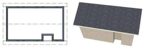
89 Adding a Roof Notice the step in the ridge line. This can be corrected by resizing the lower gable wall. Select the vertical wall to the right of the bottom gable wall and move it to the left 2 feet, reducing the length of the gable wall from 20 to 18 feet. When you are finished, rebuild the roof. This completes this Roof Tutorial. You can use any combination of the techniques described here to create a wide variety of roof planes. Let s return to our Stucco Beach House plan and apply what we have learned. Adding a Roof Now that we have a basic understanding of the automatically roof tools, let s return to our previously saved Stucco Beach House plan, as it looks like our house could use a roof now. Let s select File> Save As and give this plan a new name, such as "Beach House Roof Tutorial" before continuing. 89
90 Home Designer Architectural 2014 User s Guide To edit the default roof 1. Close any other views you may still have open. For the following steps, only the floor plan view should be open. 2. Starting on Floor 1, we will start by using the Select Objects tool to select the top horizontal exterior Kitchen wall, as indicated in the image below. 3. Click on the Open Object edit button to display the Wall Specification dialog, go to the Roof tab, place a checkmark in the Full Gable Wall option, and click OK. 4. Click Up One Floor to go to the second floor. 5. Using the Select Objects tool, select the Balcony room, then click on the he Open Object edit button to open the Room Specification dialog, and on the Structure tab, uncheck Roof Over this Room if it is selected, then click OK. 6. Open the following second floor walls specification dialogs and assign the settings shown in the following image on the Roof tab of the Wall Specification dialog. See Roof Tab on page 132 of the Reference Manual. 90
91 Adding a Roof Individual walls can be selected and edited in both 2D and 3D views. See Editing Walls on page 120 of the Reference Manual. Full Gable Wall Full Gable Wall Extend Slope Downward Full Gable Wall Full Gable Wall Full Gable Wall Extend Slope Downward Full Gable Wall 7. Once we have completed defining these walls on Floor 2, we are ready to create our roof. To turn on automatic roof generation 1. Select Build> Roof> Build Roof from the menu to open the Build Roof dialog. 2. On the Roof tab, check Auto Rebuild Roofs. See Build Roof Dialog on page 222 of the Reference Manual for more information. 3. Set the Pitch (in 12) to 3". 91

92 Home Designer Architectural 2014 User s Guide 4. You can go to the Materials tab to change the material of your roof, where we will choose an Earth Roof Tile material. 5. Click OK to close the dialog and generate a roof. 6. Recall that the additional walls you now see displayed are attic walls. 7. Select 3D> Create View> Full Overview to create a exterior view of your plan. Troubleshooting Roof Issues Creating a roof can require experimentation and practice. Here are some suggestions for troubleshooting a problematic roof design. Roof Directives in Walls As discussed in this chapter and in the Roofs chapter of the Home Designer Architectural 2014 Reference Manual, the program will automatically generate a roof plane bearing over each 92

93 Troubleshooting Roof Issues exterior wall in a plan to produce a hip roof. If you require a different condition over a particular wall, such as a triangular gable or side wall of a shed roof, you can specify that condition on the Roof tab of the Wall Specification dialog. See Roof Tab on page 132 of the Reference Manual. Specifying roof directives that do not reflect what you require directly above a selected wall, however, can often result in drastic and unwanted changes to your roof. For example, when two parallel walls are specified as Full Gable Walls, a single ridge will be created between them. If a wall that is perpendicular to these walls is also specified as a Full Gable Wall, the roof becomes more complex with an additional ridge, two valleys, and two hips. If you are seeing hips or valleys in your roof where you do not expect them, revisit the Roof tab of the walls supporting the affected roof planes. Roof Heights The heights of all roof planes are based on the heights of the walls that they bear on. Wall heights, in turn, are determined by the ceiling heights of the rooms that they define. See Floor & Ceiling Heights on page 149 of the Reference Manual. 93
 has four roof planes. This roof will become considerably more complex if one room inside is given a lowered ceiling height (in this case, 97 1/8\").")
94 Home Designer Architectural 2014 User s Guide For example, the hip roof over a simple rectangular structure with a consistent ceiling heights (in this case, 109 1/8") has four roof planes. This roof will become considerably more complex if one room inside is given a lowered ceiling height (in this case, 97 1/8"). 94

95 Troubleshooting Roof Issues If you generate a roof and it seems to be more complicated and has more roof planes than it should, take a look at the ceiling heights of the rooms in the plan. Often, the correct way to create a lowered ceiling condition will be to set the ceiling at the default height create a lowered Ceiling Finish. See Lowered Ceilings on page 150 of the Reference Manual. Controlling Roof Ridges A single roof ridge will generate for as long as the bearing walls that support the roofs on either side of the ridge are the same distance apart. When alcoves or bumpouts are introduced along either bearing wall, the ridge is likely to become broken. For example, a simple rectangular structure with Full Gable Walls at each end generates a roof with a ridge that runs from Full Gable Wall to Full Gable Wall. If a bumpout is added that affects the length of either Full Gable Wall, or if an alcove is added anywhere along the length of the structure, the ridge will no longer follow a straight line. There are a number of ways to maintain a single ridgeline in the presence of alcoves or bumpouts: 95


96 Home Designer Architectural 2014 User s Guide Use the Break Wall tool to control the length of a Full Gable Wall section. See Using the Break Wall Tool to Modify Roofs on page 86. Increase the Minimum Alcove Size to specify what size alcoves are roofed. See Roof Tab on page 222 of the Reference Manual. Use the Extend Slope Downward roof directive to allow the roof over a bumpout to extend lower then the ceiling height in that area. See Roof Directives in Walls on page 125 of the Reference Manual. Specify the area inside of an alcove as an "Open Below" room with a roof but no ceiling, and Use Soffit Surface for Ceiling specified. See Room Types on page 145 and Structure Tab on page
97 Troubleshooting Roof Issues 97
98 Home Designer Architectural 2014 User s Guide 98
99 Chapter 4: Interior Design Tutorial In the Interior Design Tutorial, we ll pick up where we left off in the House Design Tutorial. The shell and basic structure of our plan is complete, but a lot of interior finishing remains. Our plan still needs lights, outlets, and fixtures to be a functional home. In addition, the interior could use some creature comforts such as furniture, wall coverings and moldings. You may want to save this tutorial using a new name to archive your previous work. In this tutorial, you will learn about: Controlling the Display of Objects Working with Library Objects Applying Room Moldings Applying Wall Coverings Controlling the Display of Objects We have a roof on our plan, but in this tutorial we ll be working on the plan s interior, so we do not need the roof planes to show in floor plan view. As we learned in the previous tutorial when we turned off the display of attic walls, the display of objects is controlled in the Display Options dialog. For more information about layers and using the Display Options dialog, see Layers on page 63 of the Reference Manual. 99
100 Home Designer Architectural 2014 User s Guide To control the display of objects 1. First, let s make sure to select File> Save As and give this version of our plan a new name, such as "BeachHouse - Interior Tutorial" 2. Select Tools> Display Settings> Display Options (or press the ~ key) to open the Display Options dialog. 3. Press the letter R, find the layer "Roof Planes" and remove the check from the Display column. Click OK. Floor 1 with the display of door and window labels and roof planes turned off Working with Library Objects Home Designer Architectural comes with a library that contains thousands of library objects that can be used in a plan. For more information about the library and library objects, see The Library on page 355 of the Reference Manual. To use the Library Search feature to locate a symbol and place it in the plan 1. Move up to Floor 2 using the Floor Up tool. 100

101 Working with Library Objects 2. Select Library> Library Browser (or press Ctrl + L on your keyboard) to open the Library Browser. 3. Click the Turn on search filtering options button, then check Match entire word. 4. In the text field, type "bed" and notice that search results will display below as you type. 5. Click on a bed in the search results list to select it for placement. When a library object is selected for placement the mouse pointer icon indicates the type of library object selected, a preview outline of the object displays in floor plan view, and basic information displays in the Status Bar at the bottom of the program window. 6. Click in the master bedroom to place the bed. Library objects can be selected and edited using the mouse. They can also be opened for specification, a method that offers the most complete editing capabilities. See Symbol Object Specification Dialogs on page 373 of the Reference Manual. 101

102 Home Designer Architectural 2014 User s Guide To use library search to place a furniture symbol 1. Click the Select Objects button (or press the Spacebar) and click on the bed to select it. When selected, the bed displays edit handles. For more information, see Editing Box- Based Objects on page 89 of the Reference Manual. Resize edit handles Extend edit handles Move edit handle Rotate edit handle 2. Use the Rotate edit handle to rotate the bed. 3. Use the Move edit handle to move the bed up against the right wall. 4. You can modify the materials for the bed by using the Select Objects button tool to select the bed, and click on the Open Object edit button to open the Furniture Specification dialog. 102
103 Working with Library Objects 5. Next, select the Materials tab, and select the element of the object you want to apply a new material to, such as the Bedspread. 6. Click on the Library Material button to display the Select Library Object dialog, which allows you to browse materials available in the Library to apply as the bedspread. For the purposes of our example, we will choose a light brown fabric. 7. Repeat this process for any of the other materials on the bed you may want to adjust, then click OK to apply the changes which will be visible when you create a camera view. Now we ll place some fixtures. If you cannot find what you re looking for, the Library Search feature can help. To use library search to place a fixture symbol 1. Select Library> Library Browser to open the Library Browser. 2. Type toilet into the search field at the top of the browser window. As you type, search results display in the Directory pane. 3. Select the Standard toilet from the search results. 4. Click in the master bathroom to place the toilet. If there are multiple library objects in a plan that are similar, they can be replaced at the same time using the Replace From Library edit button. To replace a library object 1. While the Select Objects tool is active, click on the toilet in floor plan view to select it. 2. Click the Replace From Library edit button to open the Replace From Library dialog. 103


104 Home Designer Architectural 2014 User s Guide 3. Click the Library button to select an item from the library to replace the standard toilet. 4. Select the Elongated toilet and click OK to return to the Replace From Library dialog. 5. Select Replace Selected Object and click OK. Using the tools and techniques learned so far, place fixtures and furniture in both bathrooms on Floor 2 and Floor 1. Floor 1 104

105 Applying Room Moldings Floor 2 If existing walls and/or other objects do not allow enough room for a library object to be placed, place the library object where there is enough room and move the object into place while holding down the Ctrl key on the keyboard. Applying Room Moldings In Home Designer Architectural, you can specify base, crown and chair rail moldings for any room. We ll start by applying a crown molding in the master bedroom, and then we ll add a chair rail to the dining room. To add crown molding Now let s take a look at our master bedroom in a 3D view. See To create a camera view on page 44 for information about using thefull Camera tool. 1. With the camera view of the bedroom still active, click the Select Objects button or press the Spacebar, then click in a blank space on the floor of the room to select it. 2. Click the Open Object edit button to open the Room Specification dialog for the master bedroom. 3. On the Moldings tab: 105

106 Home Designer Architectural 2014 User s Guide Uncheck Default, and then click the Add New button. In the Select Library Object dialog, you can either search or browse to find a crown molding that suits your needs. When you find one, select it and click OK. For more information, see Select Library Object Dialog on page 370 of the Reference Manual. If you wish, you can specify the Height and Width of the selected molding. In this tutorial, a Height of 4 inches is specified. Select "Crown Molding" from the Type drop-down list and notice that the From Floor value is equal to the room s Finished Ceiling Height on the Structure tab. Click OK to close the Room Specification dialog. 106

107 Applying Room Moldings Chair rail moldings can be applied to a room in the same manner. Base moldings are already applied in most room types by default, but can be edited, removed or added here, as well. To add chair rail 1. With the camera view of the bedroom still active, click the Select Objects button or press the Spacebar, then click in a blank space on the floor of the room to select it. 2. Click the Open Object edit button to open the Room Specification dialog for the master bedroom. 3. On the Moldings tab of the Room Specification dialog: Click the Add New button, and select a chair rail profile. Specify a Height of 2" and set the From Floor value to 32" inches. Click OK. 107

108 Home Designer Architectural 2014 User s Guide Applying Wall Coverings Now we ll apply a wall covering to the master bedroom. Wall coverings can be used in addition to a wall s surface material to create accents like wallpaper borders or wainscoting. For more information about wall coverings, see Wall Materials on page 118 of the Reference Manual. To apply a wall covering 1. Select the master bedroom and click the Open Object edit button. 2. On the Wall Covering tab of the Room Specification dialog, click the Add New button to open the Select Library Object dialog. 3. Browse to an appropriate material for your wall covering, and click OK. For the purposes of our example, a Natural Beadboard material is used. 4. Change the Height to 28 inches, and change the Floor to Bottom value to 3 1/2 inches to allow for the distance between the base and chair rail moldings. 5. Click OK to close the Room Specification dialog. 108

109 Applying Wall Coverings Additional wall covering materials can be found in the Manufacturer libraries. 6. When you have finished, you may want to Save your work. If you would like, you can continue adding interior elements from the Library Browser before continuing to work on this plan in the Kitchen and Bath tutorial. 109
110 Home Designer Architectural 2014 User s Guide 110
111 Chapter 5: Kitchen and Bath Design Tutorial This tutorial continues where the Materials Tutorial left off. You should save this tutorial using a new name to archive your previous work. The tools and techniques used to design kitchens and bathrooms are very similar. This tutorial focuses on kitchen design. When you re finished you can use what you ve learned to finish up the bathrooms as well. In this tutorial you will learn about: Adding Cabinets Placing Appliances Editing Cabinets and Appliances Creating a Custom Countertop Editing Cabinets and Appliances Working in Elevation Views Adding Cabinets First, let s select File> Save As, and choose to name our plan BeachHouse - Kitchen Bath Tutorial. We ll begin by placing a cabinet in the kitchen and editing its dimensions, orientation, and placement. For more information about cabinets, see Cabinets on page 281 of the Reference Manual. To place a base cabinet 1. Zoom in on the Kitchen area in floor plan view. 2. Select Build> Cabinet> Base Cabinet. 111

112 Home Designer Architectural 2014 User s Guide 3. Click to place a base cabinet anywhere in the kitchen. Once a cabinet is placed, it can be edited like other objects. To select and edit a cabinet 1. Cabinets can be selected using one of the following methods. Click on the cabinet while the Select Objects tool is active. Click on the cabinet while any of the Cabinet Tools are active. This allows only cabinets to be selected. Right-click on the cabinet when another tool is active. 2. When the cabinet is selected, edit handles, a front indicator, and a temporary dimension display. As with other objects, the arrow that displays when the pointer is held over an edit handle indicates what edit function that edit handle will perform. See Editing Box-Based Objects on page 89 of the Reference Manual. Resize edit handles Move edit handle Front indicator Rotate edit handle Move a cabinet using the move edit handle. By default, you can move a cabinet along either the X axis or the Y axis. To allow unrestricted movement, hold down the Ctrl key (or click using the right mouse button) then drag the cabinet. Resize two sides of a cabinet using a resize edit handle, located in each corner. Extend a cabinet s edge on one side using an extend edit handle. One of the extend edit handles also displays an arrow that indicates the cabinet s front. Rotate a cabinet using the rotate edit handle. A temporary dimension updates as the cabinet is moved or resized. 3. When the cabinet is selected, you can also click the Open Object edit button to open its specification dialog and make a wide variety of changes to the cabinet. For more information, see Cabinet Specification Dialog on page 292 of the Reference Manual. 112

113 Adding Cabinets To lay out base cabinets for this tutorial 1. Place and position several initial base cabinets in your plan and edit their width and orientation as shown in the following image. Notice that two of the cabinets are 36", two are 24" wide, one is 33" and one is 27" wide. A cabinet snaps to another if they are in alignment, facing the same direction, and of the same type. Note: The display of cabinet module lines has been turned on in the following images. See Displaying Cabinets on page 287 of the Reference Manual for more information. To create corner cabinets 1. Select the three foot base cabinet at upper right. 2. Click the Open Object edit button to open the Base Cabinet Specification dialog. On the General tab: Specify a Width greater than the Depth. The selected cabinet s width should already have been changed to 36", which works well with a 24" depth. If it isn t, change it to 36" now. Click the Special drop-down list and select Corner. On the Front tab, uncheck the box beside Diagonal Door. 113
.")

114 Home Designer Architectural 2014 User s Guide Click OK to change the cabinet into a corner cabinet. 3. Repeat this process with the upper left Base Cabinet and open it for specification: On the General tab, change it to a corner cabinet (as we did in the previous step). On the General tab, change the Left Side Width to 36 inches (36"). On the Front tab, uncheck the box beside Diagonal Door if it is checked. 4. Click OK to close the Base Cabinet Specification dialog, then select this cabinet, use its rotate edit handle, then move it into the corner, until it bumps into the walls. Note: To move a group of cabinets, select one cabinet, place the pointer over the move handle, the click and drag the mouse cursor and you can push the entire group of cabinets. To place wall cabinets 1. Select Build> Cabinet> Wall Cabinet. 2. Click very above the left corner base cabinet to place a wall cabinet as shown. 114

115 Adding Cabinets 3. Click the Open Object edit button to open the Wall Cabinet Specification dialog: On the General tab, specify a Width of 33. On the Door/Drawer tab, change the Door Style to Framed Doors, and check Glass Doors if it is not already selected. On the Moldings tab, choose Add New to add a new molding profile to the cabinet. For the purposes of this example, we will use a crown molding profile set with a Height of 2 1/2", a Width of 2 1/2", and a Vertical Offset of - 2 1/2". Click OK to apply these changes to the wall cabinet. 4. Once you have finished modifying the original wall cabinet, select it and click on the Copy edit tool, then click near the opposite wall to place a second wall cabinet identical to the first, and rotate it so that it faces out in to the door, instead of in to the wall. Note: The display of cabinet face indicator lines has been turned on in the following images. See Displaying Cabinets on page 287 of the Reference Manual for more information. To place soffits Select Build> Cabinet> Soffit then click above the wall cabinets to place soffits. Adjust their width and orientation to match the wall cabinets below. 115

116 Home Designer Architectural 2014 User s Guide When objects are very close to one another or occupy the same vertical space in floor plan view, it may be difficult to select the intended object. You can select an objects, then click the Select Next Object edit button or press the Tab key to select a neighboring object. The Status Bar indicates which object is currently selected. Placing Appliances Appliances come in two basic varieties, freestanding and built-in. Most plans use both types, including this one. For more information about library objects such as appliances, see The Library on page 355 of the Reference Manual. To place a freestanding appliance 1. Select Library> Library Browser to open the Library Browser. 2. Go to Architectural> Appliances> Refrigerators, locate a refrigerator, and select it for placement. 3. On the left of the kitchen, click in the empty space to the bottom of the base corner cabinet to place the refrigerator. 116


117 Editing Cabinets and Appliances 4. In the Appliances library, find the electric range and select it for placement. 5. Place the range in the empty space on the right of the kitchen. To place a built in appliance 1. Open the Fixtures category to the Sinks library, find the double self-rimming 32 inch sink and select it for placement. For the purposes of this tutorial, we used the Offset 32" sink. 2. Click on the base cabinet near the top of the screen that is 33" wide to place the sink. 3. In the Appliances library, find a basic dishwasher, select it for placement, and click on the cabinet to the right of the sink. Editing Cabinets and Appliances We ve already learned how to edit the dimensions of cabinets and appliances in floor plan view. Like other objects, cabinets and appliances can also be edited in their own specification dialogs. This method allows a higher degree of customization. 117


118 Home Designer Architectural 2014 User s Guide To edit cabinets in the Cabinet Specification dialog 1. Select the cabinet to the left of the sink and click the Open Object edit button to open the Base Cabinet Specification dialog. 2. Select the drawer in the preview. Notice that clicking anywhere on the preview takes you to the Front tab. 3. Click the Add New button to open the New Cabinet Face Item dialog. 4. Click the Item Type drop-down list and select Cutting Board, assign an Item Height of 1 inch, and click OK to return to the Cabinet Specification dialog. 5. A new Cutting Board face item, as well as a new Separation, will be added below the drawer that you selected. 118


119 Editing Cabinets and Appliances 6. Click on the cutting board in the preview, then click the Move Up button three times to move the cutting board above the drawer and the empty spaces above and below it. 7. Select the Separation and click the Move Up button three times, as well. 8. Click OK to close the Base Cabinet Specification dialog. 9. Follow this same procedure to make any additional changes to the other cabinets in your kitchen area, such as creating a bank of drawers, or changing the handle for drawers to be knobs. 10. Finally, we will add in several smaller base cabinets to fill in the gaps between appliances To edit appliances in their specification dialogs 1. Select the refrigerator and click the Open Object edit button to open the Fixture Specification dialog. 2. On the General tab, change the Depth to 28 and click OK. 119

120 Home Designer Architectural 2014 User s Guide Creating a Custom Countertop Now we ll create a kitchen cabinet island, and add a custom countertop with an overhang. For more information, see Editing Custom Countertops on page 289 of the Reference Manual. To create a cabinet island 1. Select Build> Cabinet> Base Cabinet. 2. Click to place a base cabinet in the kitchen area, and select it. 3. Click the Open Object edit button to open the Base Cabinet Specification dialog. On the General tab, specify a Height of 33", a Width of 33" and a Depth of 27"; On the Front tab, create 3 Double Drawers each having an Item Height of 7 1/2": On the Door/Drawer tab, set the Drawer Handle to Knob; Click OK. 4. With the Base Cabinet still selected, click on the Copy/Paste edit tool, and paste a copy of this modified cabinet next to the first, as in the image below. 120


121 Creating a Custom Countertop 5. For the next portion of this tutorial, we will turn off the display of cabinet labels by selecting Tools> Display Settings> Display Options, scroll down to the Cabinets, Labels layer, remove the checkmark the Disp column, and click OK. To create a custom countertop 6. Select Build> Cabinet> Custom Countertop. 7. Click and drag to draw a rectangular polyline that will become our custom countertop. 8. Select the custom countertop and use the edit tools to edit its shape as shown in the following images, where we have applied an Angle Hatch Fill Style to the Custom Countertop for easy viewing. 121


122 Home Designer Architectural 2014 User s Guide Use the Break Line and Change Line/Arc edit buttons to add edit handles and change the polyline s shape. For more information, see Break Line on page 101 of the Reference Manual. 9. Let s create afull Camera view and take a look. 10. Finally, let s return to the Floor Plan view, add one more Wall Cabinet and Soffit above it on the right side of the kitchen, and resize them so that they are slightly wider than the Range below them. Creating Architectural Blocks Groups of items can be blocked together and saved to the library for use in other plans. 122

123 Working in Elevation Views To create an architectural block 1. While in Floor Plan view, group select all objects you would like to include in the architectural block. 2. One way to group select the objects is to hold down the Shift key and select additional objects to add them to the selection set. There are many other ways to select and group select objects. For more information, see Selecting Objects on page 76 of the Reference Manual. 3. Click the Make Architectural Block edit button. To add objects to the library 1. If it is not still selected, select the architectural block. 2. Click the Add to Library edit button to add the cabinet to the User Catalog folder in the Library Browser. 3. Right click on the Base cabinet name in the Library Browser and select Rename to change this cabinets name to Kitchen Bar. 4. Now click and drag the newly named Kitchen Bar cabinet into the appropriate User Catalog folder that you have created for it, such as Base Cabinets. To explode an architectural block 1. Select an architectural block. 2. Click the Explode Architectural Block edit button. Working in Elevation Views Like other objects, cabinets can be edited in elevation views. This method of editing is very powerful and allows objects to be edited easily in vertical space. Next we ll edit wall cabinets 123

124 Home Designer Architectural 2014 User s Guide and add a range hood. For more information about working in 3D views, see Working in 3D on page 410 of the Reference Manual. To create an elevation view 1. In floor plan view, select 3D> Create Camera View> Elevation. Click and drag a line of sight that intersects the group of cabinets that includes the range. 2. Zoom in on the kitchen. To edit the cabinets in an elevation view 1. Click the Select Objects button, then click on the wall cabinet above the range, which should have double doors and be slightly wider than the base cabinet below it. 124

 and select it for placement.")
125 Working in Elevation Views 2. Click on the cabinet s bottom edit handle and drag it upwards. 3. When the temporary dimension indicates that the cabinet height is 18 inches, release the mouse button. To place a range hood 1. Find a range hood from the Fixtures Library (Architectural> Appliances> Hoods> Large) and select it for placement. 2. Click above the range to place the hood. 3. If necessary, adjust its height and size using its edit handles. 125
.")
126 Home Designer Architectural 2014 User s Guide Finishing Touches You may want to add a few finishing touches. While we re at it, let s add some additional interior design elements from the Library Browser, including stools to our new bar in the kitchen (Interiors> Furniture> Seating> Stools). Add furniture to the dining nook and change the flooring to match the kitchen. Add a table and some chairs to the dining area. Continue placing objects from the Library Browser to customize the remainder of the house design. To view our kitchen using the Cross Section Slider and Final View 1. In floor plan view, click Fill Window. 2. Create a Full Camera view that starts from the exterior and release the mouse button in the kitchen. See To create a camera view on page Use the Mouse-Orbit Camera tool to adjust the camera s perspective. If you want, you can turn off the display of the backdrop in the 3D Backdrop dialog. For more information, see 3D Backdrop Dialog on page 396 of the Reference Manual. 4. Select 3D> Cross Section Slider to open the Cross Section Slider dialog. 5. Select the flat cut line and use the position slider to specify the location of the cutting plane. See Cross Section Slider on page 409 of the Reference Manual. 6. Select 3D> Final View to create a higher quality final view. 126

127 Working in Elevation Views 7. In a future tutorial, we will be returning to this plan file, so be sure to Save your work. If you would like, you can continue working on this plan in the Landscaping Tutorial. 127
128 Home Designer Architectural 2014 User s Guide 128
129 Chapter 6: Materials Tutorial Materials display on the surfaces of objects in 3D views and can make a 3D view appear highly realistic. When applied to most objects, material quantities will also be calculated in the Materials List. This tutorial continues from where the Interior Design Tutorial ended. You may want to save this tutorial using a new name to archive your previous work. In this tutorial you will learn about: Setting Materials Defaults Using the Materials Tab Using the Material Painter Using the Material Eyedropper Blending Colors with Materials Using the Material Eyedropper Custom Materials, Images, and Backdrops Generating a Materials List Setting Materials Defaults Material default settings determine the materials used by different objects when they are initially created. Setting the correct material defaults before beginning a project may help you save time. For more information, see Preferences & Default Settings on page 49 of the Reference Manual. 129


130 Home Designer Architectural 2014 User s Guide To set material defaults 1. Select Edit> Default Settings to open the Default Settings dialog. 2. There are a two options. You can do either or both: Select an item in the tree list and click the Edit button to open the defaults dialog for that type of object. The default dialogs for architectural objects such as doors and windows have a Materials tab that allows you to set the material defaults for object components. See Using the Materials Tab on page 131. Select Materials and click the Edit button to open the Material Defaults dialog. Here you can set the material defaults for many different objects, including some that do not have default dialogs. See Material Defaults on page 385 of the Reference Manual. 130

131 Using the Materials Tab 3. When you are finished, click OK to close the defaults dialog, then click Done to close the Default Settings dialog. Once an object has been placed in a plan, the materials applied to it can be changed in a number of ways. Using the Materials Tab Most objects materials can be assigned in their specification dialog in both 2D and 3D views. The materials used by a door, for example, can be edited on the Materials tab of the Door Specification dialog. For more information, see Materials Tab on page 380 of the Reference Manual. To change material on an object using the Materials tab 1. Click the Select Objects button, then click on the double door leading from the master bedroom to the deck on Floor 2 to select it. 2. Click the Open Object edit button to open the Door Specification dialog. 3. Select one of the door s components from the list on the left. Click the Select Material button to open the Select Library Object dialog. 131
132 Home Designer Architectural 2014 User s Guide 4. Find and select a material and click OK. 5. You can continue to specify component materials. The preview in the dialog updates as changes are made. When finished, click OK to close the specification dialog. 6. Create a Camera view of the door. The materials used in individual rooms can also be specified. Rooms can be selected in both floor plan and 3D views. In floor plan view, click in an empty space within a room. When selected, the whole room is highlighted. If you accidentally select an object other than the room, you can press the Tab key on the keyboard until the room is selected. In camera views and overviews, click on the floor of the room to select it. To edit a room using the Materials tab 1. Select the master bedroom and click the Open Object to open the Room Specification dialog. 2. On the Materials tab, select Molding under the Crown Molding heading and click the Select Material button to open the Select Library Object dialog. 132

133 Using the Material Painter 3. Find and select a material and click OK to close the dialog. 4. Click OK to close the Room Specification dialog. 5. The results can be seen in a Full Camera view. Using the Material Painter The Material Painter 3D view. tool allows you to select a material and then apply it to an object in a 133

134 Home Designer Architectural 2014 User s Guide There are five Material Painter Modes which specify how broadly or narrowly the selected material will be applied to surfaces in your plan. In this tutorial, the Component Mode is used. For more information, see The Material Painter on page 378 of the Reference Manual. To apply a material using the Material Painter 1. While still in the 3D view of the door, select 3D> Material Painter and confirm that there is a checkmark next to Material Painter Component Mode. 2. Click the Material Painter button to open the Select Library Object dialog. Browse to Flooring> Carpeting, select a carpet material, and click OK. 3. Move your cursor into the 3D view and notice that it displays a spray can icon. 134
135 Using the Material Painter 4. Click on the floor of the master bedroom to apply the selected material to that surface, which is a component of the room. As an alternative to wall-to-wall carpeting, you can place an area rug symbol from the library in a room and assign to it whatever material you wish. See Placing Library Objects on page 368. With the Material Painter tool you can apply a material to nearly any surface, including many that can t be individually selected like the base molding on a wall or the frame of a window. When either the Component or Object Modes is active, you can continue to apply the selected material to objects until a different tool is selected. To add artwork to a frame 1. A variety of frames can be found in the Interiors library category. Place a wall or desk frame in your plan and create a camera view in which it can be seen. 2. Select 3D> Material Painter and confirm that there is a checkmark next to Material Painter Component Mode. 3. Click the Material Painter button to open the Select Library Object dialog and select a painting, photo or print from the Artwork library. 135

136 Home Designer Architectural 2014 User s Guide 4. Move your cursor over the middle area of the frame and click to apply the selected artwork. The artwork displayed in a frame can also be specified in the frame s specification dialog. See Symbol Object Specification Dialogs on page 373 of the Reference Manual. Blending Colors with Materials Instead of using the Material Painter to replace a material with a new one, we can use it with the Blend Colors With Materials feature to blend a color with a textured material such as the carpet we selected for the master bedroom and create a new material. For more information, see Blend Colors With Materials on page 379 of the Reference Manual. To blend a color with a texture 1. In a 3D view, select 3D> Material Painter> Material Painter. 2. In the Select Library Object dialog, select a solid color for the carpet from the Generic Colors library, then click OK. 3. When you move your cursor into the view, it displays a paint roller icon. When Blend Colors with Materials is active and a solid color is loaded in the Material Painter, your cursor displays the paint roller icon. If you see the spray can icon instead, select 3D> Material Painter> Blend Colors With Materials to turn this feature on. 136
137 Using the Material Eyedropper 4. Click on the carpet to blend the selected color with the carpet texture. The result is a new material with the textured appearance of the carpet as well as the color you selected. Using the Material Eyedropper The Material Eyedropper tool allows you to load a material that can be seen on a surface in a 3D view into the Material Painter tool and then apply it to another surface. In our master bedroom, the type of wood we have assigned to the interior trim of the exterior door is 137
138 Home Designer Architectural 2014 User s Guide different than the material used on the trim of the interior doors.we can easily change this using the Material Eyedropper. 1. Activate the camera view (or any 3D view). 2. Select 3D> Material Painter> Material Painter from the menu. If there is a check beside Blend Color With Material, select this menu item to disable it; if not, simply click outside of the menu to close it again. 3. Select 3D> Material Painter> Material Eyedropper and notice that the pointer displays an eyedropper icon. 138

139 Custom Materials, Images, and Backdrops 4. Now just click to load that material. Notice that the pointer changes to a spray can, indicating that the loaded material is ready to apply to another object and replace the existing material. 5. Click on the moldings to apply the loaded material. Custom Materials, Images, and Backdrops Home Designer Architectural allows you to customize your 3D views by importing your own materials, image objects, and backdrops that display in 3D views. For more information about images, see Pictures, Images, & Walkthroughs on page 473 of the Reference Manual. Note: The following steps make use of image files that are not included with the program. You can use image files that are already on your computer or you can create new ones. You can even use the same image file to create a material, an image, and a backdrop. Learning the tools and techniques described is more important than the appearance of the final product. Creating Materials Materials are special digital images that can be applied to the surfaces of objects. You can create your own custom materials and save them in the library. Bear in mind that materials typically cover a surface by tiling an image repeatedly and are specially edited so that they tile seamlessly: as a result, not all images will necessarily serve as effective materials. Once a material is saved in the library, it can be applied to objects in any plan, either using the objects specification dialogs or the Material Painter tool. 139

140 Home Designer Architectural 2014 User s Guide To add a new material to the library 1. Select Library> Library Browser (or press Ctrl + L) to open the Library Browser. 2. Right-click on the User Catalog folder and select New> Material from the contextual menu to open the Define Material dialog. 3. Give the new material a short, descriptive Name. 140

141 Custom Materials, Images, and Backdrops 4. On the Texture tab, click the Browse button to display the Select Texture File dialog, where you can select an image file saved on your machine. 5. Select an image file and click the Open button to return to the Define Material dialog. 6. Specify the Scale of the texture, which controls how large the image will appear on the surfaces it is applied to. 7. Click OK to add the new material to the User Catalog folder. For more information, see Define Material Dialog on page 383 of the Reference Manual. Creating Images In Home Designer Architectural, image objects are more than just 2D pictures. Images have size and height attributes and can contain transparency information. In floor plan view, they display only as 2D symbols; but in 3D views, the visual information that images contain can be seen. Images can be placed in a plan just as plants, furnishings and fixtures are: by selecting the image and clicking any floor plan view, camera view or overview. To create an image and save it to the library 1. Right-click on the User Catalog folder, then select New> Image from the contextual menu to open the Image Specification dialog. For more information, see Image Specification Dialog on page 476 of the Reference Manual. 141

142 Home Designer Architectural 2014 User s Guide 2. On the Image tab, click the Browse button and browse to any image on your computer. In this tutorial we will use an image of a cat that has transparency data associated with it; however, you can use any image. 3. Click Open to return to the Image Specification dialog. 4. On the Image tab, enter the Height or Width, adjusting one will adjust the other, maintaining the correct proportion. Enter a Height Above Ground value to specify the elevation at which the image displays. A value of 24 inches works well in this case as we ll be placing the image on a piece of furniture. 5. Specify the transparency settings on the Transparency tab. 6. Click OK to close the Image Specification dialog and add the new image to the My Images category in the Images library. Importing Backdrops Backdrops are images that display behind 3D views. In Home Designer Architectural, you can take a photo of a site, save it to the library as a backdrop, and display it behind 3D views to create a realistic rendering of your model and its surrounding view. 142
143 Custom Materials, Images, and Backdrops To import a backdrop and save it to the library 1. Select File> Import> Backdrop and browse to an image on your computer. 2. Select the image and click Open to add it to User Catalog. To apply a backdrop to 3D views 1. Select 3D> 3D Backdrop to open the 3D Backdrop dialog. 143


144 Home Designer Architectural 2014 User s Guide 2. Click on the Select Backdrop button, find and select your backdrop from User Catalog and click OK. 3. Click OK to close the 3D Backdrop dialog. You can see your custom material, image and backdrop by creating a Full Camera view. 144
145 Generating a Materials List Generating a Materials List To conclude this tutorial, we ll generate a materials list for the house. You can generate a materials list for a single room, an area of the plan on one floor, or the whole plan. For more information, see Materials Lists on page 515 of the Reference Manual. Note: The Materials List is only a rough cost estimate and should be double checked before being relied on. To generate a materials list for the whole plan 1. Select Tools> Materials List> Calculate From All Floors. A materials list is generated for all floors of the house. 2. Locate the an item, such as one under the Fixtures category. 3. Click in the Price column type in a value. Notice that the subtotal and Total both update to reflect the pricing change. You can specify prices for every material in your plan, allowing you to generate a cost estimate. 4. If you wish, you can select File> Export Materials List and save the list as a Tabdelimited.txt file, which can be opened in a spreadsheet application. 5. Close the materials list by selecting File> Close Window from the menu. When you have finished, you may want to Save your work. You can generate a materials list to estimate the cost of an entire plan or just a portion of a plan. For more information, see Materials Lists on page 515 of the Reference Manual. Note: The Materials List is only a rough cost estimate and should always be double checked before being relied on. To calculate a materials list for an individual room 1. Click the Select Objects button, then click in a room to select it. 2. With the room selected, click the Calculate from Room edit button or select Tools> Materials List> Calculate from Room. The program calculates a list of the objects and materials contained in the selected room. To calculate a materials list for just the deck 1. In floor plan view, select Tools> Materials List> Calculate from Area. 2. Click and drag a rectangle surrounding the an area to display a materials list for the area within the rectangle. The resulting materials list only includes objects and materials located within the rectangle. 145
146 Home Designer Architectural 2014 User s Guide 146
147 Chapter 7: Landscaping Tutorial This tutorial was written to help you learn how to use Home Designer Architectural s Terrain tools. In this tutorial, you will learn how to add elevation information to your terrain, how to create terrain features, and how to add plants and other objects from the library. It is a good idea to become familiar with the terrain tools before beginning your own terrain project. In this tutorial, you will learn about: Creating a Terrain Perimeter Creating a Walkout Basement Creating a Retaining Wall Adding a Driveway Adding Library Objects to Your Plan This tutorial continues from where the House Design Tutorial left off, so you may want to save this plan using a new name to archive your previous work. 147
148 Home Designer Architectural 2014 User s Guide Creating a Terrain Perimeter The Terrain Perimeter is a closed polyline that defines the boundary of the terrain that generates in 3D views, and of the contour lines that generate in floor plan view. It can also be used to represent a lot boundary. See Terrain Perimeter on page 301. To create and resize a terrain perimeter 1. On Floor 1 of your plan, select Terrain> Create Terrain Perimeter from the menu or click the corresponding toolbar button. See Toolbar Arrangement on page 62 of the Reference Manual. If this menu option is not available in a given plan file, a terrain perimeter already exists. 2. Select Window> Fill Window to fill the screen with the terrain perimeter. 3. Select the terrain perimeter by clicking on either of the vertical edges. Notice that a temporary dimension displays, indicating that the selected edge of the terrain perimeter is 100 feet from the opposite edge. 4. With the terrain perimeter edge selected, click on the temporary dimension. Enter 150 feet using an apostrophe to denote feet (150 ). The program will default to inches if no apostrophe is included. For more information about using dimensions to relocate objects, see Moving Objects Using Dimensions on page 438 of the Reference Manual. 5. Press the Enter key on your keyboard and repeat this process for the adjacent edge of the terrain perimeter, creating a rectangle that is 150 feet by 200 feet. 148


149 Creating a Terrain Perimeter 6. Click Window> Fill Window to fill the screen with the terrain perimeter. The Reference Grid, or Virtual Graph Paper, is a visual aid that helps create a sense of scale when drawing. Grid squares are 12 inches per side. The Reference Grid is turned off for these tutorials but can be turned on or off in the Plan Defaults dialog. See General Plan Defaults Dialog on page 51 of the Reference Manual. Your house may already be centered on the terrain perimeter. If it is not, you can move it. To move the terrain perimeter 1. Select the terrain perimeter and place your pointer over the move edit handle. 2. Move the terrain perimeter so that the house is centered. 149

150 Home Designer Architectural 2014 User s Guide To edit the shape of the terrain perimeter 1. In addition to adjusting the size of your rectangular terrain perimeter, you can also use the Change Line/Arc and Break Line edit tools to modify its shape. 2. To place a break on the right segment of the Terrain Perimeter, creating a new corner edit handle at that location, and two separate edges on either side of that handle, use the Break Line edit tool. 3. You can then use the edit handle to adjust the size and shape of the Terrain Perimeter. For more information, see Editing Closed-Polyline Based Objects on page 86 of the Reference Manual. 4. Select the bottom edge of the Terrain Perimeter, and click on the Change Line/Arc edit button, and notice that this segment changes in to an Arc, which can then be modified using its edit handles. For more information on modifying arcs, see Editing Arc Based Objects on page 80 of the Reference Manual. 150

151 Creating a Walkout Basement 5. Once you have finished modifying your terrain perimeter, you are ready to move on to the next section of the tutorial. Creating a Walkout Basement Our terrain is currently flat because there is no elevation data in the plan. For more information about elevation information, see Elevation Data Tools on page 303 of the Reference Manual. To add elevation information to your plan 1. Select Window> Fill Window to fill the window with the terrain perimeter. 2. Using the Select Objects tool, select the Terrain Perimeter and click on the Open Object edit button to display the Terrain Specification dialog. 3. On the General tab, make sure Flatten Pad and Auto Calculate Elevation are unchecked, and change the Elevation to 12 inches. 151

152 Home Designer Architectural 2014 User s Guide Flatten Pad flattens the building pad around the house. By unchecking this, the terrain will be allowed to slope where it intersects the house. Auto Calculate Elevation places the house at average terrain height. By unchecking this, we can control the building s height relative to the terrain. The Elevation is the distance between the default floor height of Floor 1 and a terrain elevation of 0". We will specify the Elevation as 12 inches to lower the terrain 12 inches below the first floor. 4. Click OK to close the Terrain Specification dialog. 5. Next, Select Terrain> Elevation Data> Elevation Line and draw elevation lines as shown in the following image. An elevation line drawn near the end of another will merge. 6. To enter elevation information, click the Select Objects button, select an elevation line, and click the Open Object edit button to open the Elevation Line Specification dialog. Values entered are in inches unless the foot ( ' ) mark is added. Negative values should be preceded with a hyphen (-). 152

153 Creating a Retaining Wall 7. Select 3D> Create View> Full Overview to create a full overview. Pressing the I key or the O key moves the camera in or out. Creating a Retaining Wall Adding a retaining wall helps create a flat building pad near the garage. For more information see Retaining Walls on page 311 of the Reference Manual. 153
154 Home Designer Architectural 2014 User s Guide To draw a retaining wall 1. Return to floor plan view. Note the generated contours. 2. To make it easier to draw, you can turn off the display of primary contour lines in 2D. Select Tools> Display Settings> Display Options to open the Layer Display Options dialog. Remove the check from the Disp column for the layer Terrain, Primary Contours. See Display Options Dialog on page 65 of the Reference Manual for more information. Open 3D views are redrawn whenever changes are made to the plan, even if the 3D views are not active. Closing 3D views when they are not needed will help maximize your computer s performance. 3. Select Terrain> Wall and Curb> Straight Retaining Wall. Draw two straight wall sections as shown in the following image. 154
155 Creating a Retaining Wall 4. Select Terrain> Wall and Curb> Curved Retaining Wall and draw a curved retaining wall that connects at both ends to the two straight sections. Don t worry about the angle just yet, we ll adjust the curve in the next step. 5. Click the Select Objects button, then click and drag the small triangular edit handle that displays along the curved wall. As you drag this handle, the curved wall s radius changes. 6. Now add two more Elevation Lines just inside the retaining wall. This helps designate the height of this area when terrain is generated. This elevation line can stay at its default height of 0'


156 Home Designer Architectural 2014 User s Guide 7. Take a look in a Full Overview. Your plan should look similar to the image below. Adding a Driveway Now we ll add a driveway to our plan. To add a driveway to the plan 1. Select File> Close to return to floor plan view. You should still be on Floor Click the Fill Window button to fill your screen with the terrain perimeter. 3. Turn off the display of the layer, "Terrain, Primary Contours". If you cannot remember how to do this, see Creating a Retaining Wall on page

157 Adding a Driveway 4. Select Terrain> Road and Sidewalk> Driveway Area then click and drag to draw a driveway. Once drawn, you can edit the driveway s shape using its edit tools. To edit the driveway s shape 1. Click the Select Objects button, then click on the driveway to select it. 2. Click the Break Line edit button, then click along any edge of the driveway to place a new corner edit handle at that location. The edge that you clicked on becomes divided into two edges that join at the new handle. 3. Continue adding breaks to create as many edges as you wish. Click the Select Objects button when you are finished. 4. With the Select Objects tool active, click and drag any of the edit handles that display along the edges of the driveway to adjust its shape and size as needed. 5. If you would like to change a straight edge into a curved edge, click on that edge to select it and click the Change Line/Arc edit button. 6. To change a curved edge back into a straight edge, select it and click the Change Line/Arc edit button once more. 7. Next, add in a Terrain> Road> Straight Road and Terrain> Sidewalk> Straight Sidewalk to complete the design. 157

158 Home Designer Architectural 2014 User s Guide 8. Finally, take a look at your plan in an Overview to see the results. Recall that you can select 3D> Final View to smooth surface edges and improve the quality of the view. 158
159 Adding Terrain Features Adding Terrain Features Now we ll add a beach, a water line, and a pathway to our plan. For more information about terrain features, see Terrain Feature Tools on page 307 of the Reference Manual. To create a beach 1. Close the overview and return to floor plan view. 2. Select Window> Fill Window then select Window> Zoom Out to give us some working space outside the terrain perimeter. 3. Select Terrain> Feature> Rectangular Feature and draw a terrain feature that extends to the boundaries of the terrain perimeter. 4. Select the terrain feature and the Open Object edit button to open the Terrain Feature Specification dialog. On the General tab, the Height should be at 0 inches. On the Materials tab, select the terrain feature and click the Select Material button to open the Select Library Object dialog and assign a sand material from the landscaping library. Click OK to close the Select Library Object dialog then click OK to close the Terrain Feature Specification dialog and return to floor plan view. 5. With the Terrain Feature still selected, use the Break Line edit tool to place two breaks in the front of the rectangular feature. 6. Next, select one of the segments you have created, and click the Change Line/Arc edit tool, and use the triangular edit handle to adjust the shape of the curved segment, and 159


160 Home Designer Architectural 2014 User s Guide repeat this procedure for the remaining front segments of the Terrain Feature, as in the image below. 7. Take a look at our new beach in a Perspective Full Overview. To create a body of water 1. Return to floor plan view, select Terrain> Water Feature> Round Pond and draw another spline feature, within the existing terrain feature (the beach) and resize it similar to the image below. 2. Select the pond and click the Open Object edit button. On the General tab of the Terrain Feature Specification dialog, raise the Height to 1 inch. This will display the water material above the beach. 160


161 Adding Terrain Features 3. Click OK and take a look in a Perspective Full Overview. Notice that only the portion of the terrain feature that is included within the terrain perimeter is modeled. 4. Using the method described above, you can quickly see how it is easy to create a terrain features, customize their height, material, shape and even combine them together to create nearly any type of terrain feature you might want in your plan. To use an Elevation Region An Elevation Region contains absolute elevation data for an enclosed region and is ideal for creating a flat surface in your terrain. 1. Select Terrain> Elevation Data> Elevation Region to activate the tool, then click and drag out a rectangular region to the right of the structure in front of the door. 161


162 Home Designer Architectural 2014 User s Guide 2. Once the Elevation Region is placed, select it and click on the Open Object edit tool to display the Elevation Region Specification dialog, and enter in an Elevation of Click OK and take a look in a Perspective Full Overview to see the changes that this makes for our Terrain. 4. Let s return to floor plan view and select Build> Stairs> Click Stairs, then click outside of the doorway to create a set of stairs from our door down to the terrain of our newly created Elevation Region. 162

163 Adding Terrain Features To use a Terrain Modifier A typical walkout basement has an upper flat region where you enter the house on the first floor, and a lower flat region where you walk out to ground level from the basement. 1. In floor plan view, select Terrain> Modifier> Flat Region and draw a flat region directly in front of the Kitchen windows. 2. If you have not already placed a door for your walkout basement, select Tools> Reference Floors> Down One Floor and place a door in the wall below the kitchen windows. 3. Click OK and take a look in a Perspective Full Overview to see the changes that this makes for our walkout basement. 163

164 Home Designer Architectural 2014 User s Guide Adding Library Objects to Your Plan The library contains many objects that can be added to a plan such as plant images and landscaping blocks. There are two ways to find objects in the library: by browsing and by searching. For more information about library objects, see The Library on page 355 of the Reference Manual. To browse the Plants library category 1. If the Library Browser is not open, select Library> Library Browser to open it. 2. Click the + beside Plants to expand this category and see its contents. 3. Click the + beside Trees to expand this folder and view its contents, as well. 4. Expand the Deciduous folder and note the many tree species to choose from. Many of these folders contain still more subfolders with different varieties of that species. If you know exactly what tree you would like to place in your plan, browsing to it is an efficient way to find and select it; however, with so many options available it is often helpful to perform a search. To search using the Plant Chooser 1. With the Library Browser still open, click the Plant Chooser button at the bottom of the Library Browser to open the Plant Chooser dialog. This dialog can also be opened by selecting Terrain> Plant> Plant Chooser. 2. On the Plant Information tab, enter palm in the Common Names field, and click the Search button to find palm trees in the Library Browser. 164

165 Adding Library Objects to Your Plan 3. Select a Cocos nucifera from the search results and click the Close button. This locates and selects this plant in the Library Browser for placement. 4. Click in floor plan view or a 3D view to place the selected plant at that location. You can continue placing the selected plant image until another tool or library object is selected. 5. In floor plan view, click the Select Objects button, select the stepping stone, click the Copy/Paste edit button, then click the Sticky Mode secondary edit button. 6. Click in floor plan view to paste copies of the group selected objects. Continue pasting copies until you have created a pathway that leads to the house. 7. Repeat this process for any additional plants or groupings of plants that you want to place in your design. 165

166 Home Designer Architectural 2014 User s Guide 1. In the Library Browser, browse to the Chief Architect Core Catalogs folder. 2. The Exteriors library contains a selection of landscaping, deck and patio accessories, outdoor furniture, and other objects that you can place in your plan. 3. Outdoor furniture such as a garden bench are located in the Outdoor Living library folder. Library objects may need to be rotated, and can be accented with additional plants. 4. Additional objects, such as Fencing, Sprinkler Heads, exterior fixtures, and other library browser objects such as rocks can also be added to customize your designs landscaping. 5. Once you have completed adding items to your landscaping design, create a Full Camera view to see the results. 166

167 Adding Library Objects to Your Plan 167
168 Home Designer Architectural 2014 User s Guide 168
169 Chapter 8: Deck Tutorial Now we ll continue where the Landscaping Tutorial left off and create a deck off the back of the house, connecting it to the terrain with an exterior staircase. You may want to save this tutorial using a new name to archive your previous work. In this tutorial you will learn about: Decks and Porches Drawing Decks Drawing Stairs Changing Planking Orientation Adding Exterior Furniture Decks and Porches Decks and porches are exterior rooms that are defined by the deck railings and exterior walls that enclose them. When an exterior room is drawn using the Deck Railing tool, the room is automatically assigned the exterior room type Deck. Railings and Deck Railings are drawn just like walls. To illustrate this, we ll add a deck behind the kitchen area. For more information see The Deck Tools on page 109 of the Reference Manual. 169

170 Home Designer Architectural 2014 User s Guide Drawing Decks To draw a deck 1. To begin, while in floor plan view, let s select Tools> Display Settings> Display Options and uncheck the Disp for both the "Terrain, Elevation Data" and "Plants" layers and click OK. 2. In floor plan view, go to the first floor (you may be there already). 3. Make sure Angle Snaps a are turned on. 4. Zoom in on the back portion of the house. 5. Next select Build> Deck> Straight Deck Railing. 6. Draw five deck railings as shown in the following image. The angled railings are drawn at a 45 degree angle to the others. Note that when the mouse is released, the room is assigned the Room Type of Deck and given a room label. 7. When the deck area is enclosed, click the Select Objects button, then click in this room to select it. 8. Click the Open Object edit button to display the Room Specification dialog. 9. On the Structure tab we will set the Floor (C) value to -108" so that it will generate at the door for our walkout basement then click OK. Note that Deck rooms by default will not automatically generate a Roof or Ceiling over the room, however, you can still select these options. We will leave the checkboxes alone for the purposes of this tutorial. 170

171 Drawing Stairs 10. Now take a look at our first floor deck in a Camera view. You can see that the program automatically generated planking, posts, and beams. 11. Select Window> Tile Vertically to see a side by side of both the 2D and 3D views. Drawing Stairs Now we ll draw stairs between the deck to the terrain below. For more information, see Stairs, Ramps & Landings on page 235 of the Reference Manual To connect the upper and lower decks with stairs 1. In the floor plan view window, make sure that you are on the first floor. 2. Make sure Angle Snaps are turned on. 3. Select Build> Stairs> Click Stairs. 4. Click just to the outside of the deck platform, as shown in the following image. 171

172 Home Designer Architectural 2014 User s Guide 5. In most cases when using the Click Stairs tool, an opening will be added automatically to the deck railing at the top of a staircase. 6. If an opening is not created, select Build> Door> Doorway in either floor plan or a 3D view, then click on the deck railing to create an opening in front of the staircase. Changing Planking Orientation The angle of the deck planking can be controlled in the Room Specification dialog. To angle deck planking 1. Close the Camera view, and return to just the floor plan view being active. 2. Next, turn back on the display of the layer "Framing, Deck Planking" so we can see the angle of the planking in floor plan view. 172


173 Changing Planking Orientation 3. Select the Deck room. You will likely select an individual plank. Click the Select Next Object edit button or press the Tab key until the room is selected. 4. With the Deck room selected, click the Open Object edit button and go to the Deck tab of the Room Specification dialog. 5. On the Deck tab, uncheck the Automatic checkbox next to Plank Direction, and then change the Plank Direction to 45. See Deck Tab on page 157 of the Reference Manual. 173


174 Home Designer Architectural 2014 User s Guide 6. Click OK to close the Room Specification dialog and return to floor plan view. Adding Exterior Furniture Now let s add some furniture to our deck. To add furniture to the deck 1. Open the Library Browser and browse to Home Designer Core Catalogs> Exteriors> Outdoor Living> Outdoor Furniture> Furniture Sets> Wicker> Wicker Dining Chair and select it for placement. When a library item is selected, a preview image displays. 174

175 Adding Exterior Furniture 2. In floor plan view or a 3D view, click on the deck to place a chair symbol. You can continue clicking to place more chairs. 3. Find Home Designer Core Catalogs> Exteriors> Outdoor Living> Outdoor Cooking, select a grill for placement, and place it on the deck. 4. Next, add some exterior lighting and any other desired exterior elements to your deck design. 5. Finally, create a Camera view to see the results. 175

176 Home Designer Architectural 2014 User s Guide 176
House Design Tutorial
 Chapter 2: House Design Tutorial This House Design Tutorial shows you how to get started on a design project. The tutorials that follow continue with the same plan. When we are finished, we will have created
House Design Tutorial
 Chapter 2: House Design Tutorial This House Design Tutorial shows you how to get started on a design project. The tutorials that follow continue with the same plan. When you are finished, you will have
House Design Tutorial
 Chapter 2: House Design Tutorial This House Design Tutorial shows you how to get started on a design project. The tutorials that follow continue with the same plan. When you are finished, you will have
House Design Tutorial
 House Design Tutorial This House Design Tutorial shows you how to get started on a design project. The tutorials that follow continue with the same plan. When you are finished, you will have created a
Chief Architect Home Designer Architectural User s Guide
 Chief Architect Home Designer Architectural 2017 User s Guide Chief Architect, Inc. 6500 N. Mineral Dr. Coeur d Alene, Idaho 83815 www.homedesignersoftware.com 1990 2016 by Chief Architect, Inc. All rights
House Design Tutorial
 House Design Tutorial This House Design Tutorial shows you how to get started on a design project. The tutorials that follow continue with the same plan. When you are finished, you will have created a
Chief Architect Home Designer Professional User s Guide
 Chief Architect Home Designer Professional 2019 User s Guide Chief Architect, Inc. 6500 N. Mineral Dr. Coeur d Alene, Idaho 83815 HomeDesignerSoftware.com 1990 2018 by Chief Architect, Inc. All rights
Chief Architect X8 User s Guide
 Chief Architect X8 User s Guide Professional Design & Drafting Software Chief Architect, Inc. 6500 N. Mineral Dr. Coeur d Alene, Idaho 83815 chiefarchitect.com 1990 2015 by Chief Architect, Inc. All rights
Chief Architect X9 User s Guide
 Chief Architect X9 User s Guide Professional Design & Drafting Software Chief Architect, Inc. 6500 N. Mineral Dr. Coeur d Alene, Idaho 83815 chiefarchitect.com 1990 2017 by Chief Architect, Inc. All rights
Roof Tutorial Wall Specification
 Roof Tutorial The majority of Roof Tutorial describes some common roof styles that can be created using settings in the Wall Specification dialog and can be completed independent of the other tutorials.
Landscaping Tutorial. Chapter 5:
 Chapter 5: Landscaping Tutorial This tutorial was written to help you learn how to use Home Designer Landscape and Deck s Terrain tools. In this tutorial, you will learn how to add elevation information
Deck Tutorial. Chapter 8: Decks and Porches
 Decks and Porches Chapter 8: Deck Tutorial Now we ll continue where the Landscaping Tutorial left off and create a deck off the back of the house, connecting it to the terrain with an exterior staircase.
Landscaping Tutorial. Adding a Driveway Adding Library Objects to Your Plan
 Landscaping Tutorial This tutorial describes how to use Home Designer Pro s Terrain Tools. In it, you will learn how to add elevation information to your terrain, how to create terrain features, and how
Deck Tutorial. Chapter 6: Decks and Porches
 Chapter 6: Deck Tutorial Now we ll continue where the Landscaping Tutorial left off and create a deck off the back of the house, connecting it to the terrain with an exterior staircase. You may want to
Deck Tutorial. Chapter 8: Decks and Porches
 Chapter 8: Deck Tutorial Now we ll continue where the Landscaping Tutorial left off and create a deck off the back of the house, connecting it to the terrain with an exterior staircase. You may want to
Landscaping Tutorial
 Landscaping Tutorial This tutorial describes how to use Home Designer Architectural s Terrain Tools. In it, you will learn how to add elevation information to your terrain, how to create terrain features,
Kitchen and Bath Design Tutorial
 Kitchen and Bath Design Tutorial This tutorial continues where the Interior Design Tutorial left off. You should save this tutorial using a new name to archive your previous work. The tools and techniques
Kitchen and Bath Design Tutorial
 Kitchen and Bath Design Tutorial This tutorial continues where the Interior Design Tutorial left off. You should save this tutorial using a new name to archive your previous work. The tools and techniques
Deck Tutorial. Decks and Porches. Drawing Decks
 Deck Tutorial The Deck Tutorial continues where the Landscaping Tutorial left off, and explains how to create a deck off the back of the house and connect it to the terrain with an exterior staircase.
Kitchen and Bath Design Tutorial
 Adding Cabinets Chapter 5: Kitchen and Bath Design Tutorial This tutorial continues where the Materials Tutorial left off. You should save this tutorial using a new name to archive your previous work.
Materials Tutorial. Setting Materials Defaults
 Materials Tutorial Materials display on the surfaces of objects in 3D views and can make a 3D view appear highly realistic. When applied to most objects, material quantities will also be calculated in
Materials Tutorial. Chapter 6: Setting Materials Defaults
 Setting Materials Defaults Chapter 6: Materials Tutorial Materials display on the surfaces of objects in 3D views and can make a 3D view appear highly realistic. When applied to most objects, material
CAD Tutorial. CAD Detail Windows. In this tutorial you ll learn about: CAD Detail Windows Exploding and Modifying a CAD Block
 CAD Tutorial In this tutorial you ll learn about: CAD Detail Windows Exploding and Modifying a CAD Block Creating a New CAD Block CAD Detail from View Creating a Plot Plan CAD Detail Windows CAD Details
Getting Started. with Easy Blue Print
 Getting Started with Easy Blue Print User Interface Overview Easy Blue Print is a simple drawing program that will allow you to create professional-looking 2D floor plan drawings. This guide covers the
ARCHICAD Introduction Tutorial
 Starting a New Project ARCHICAD Introduction Tutorial 1. Double-click the Archicad Icon from the desktop 2. Click on the Grey Warning/Information box when it appears on the screen. 3. Click on the Create
Materials Tutorial. Chapter 6: Setting Materials Defaults
 Setting Materials Defaults Chapter 6: Materials Tutorial Materials display on the surfaces of objects in 3D views and can make a 3D view appear highly realistic. When applied to most objects, material
Landscaping Tutorial
 Landscaping Tutorial This tutorial describes how to use Home Designer Essentials s Terrain Tools. In it, you will learn how to add elevation information to your terrain, how to create terrain features,
Learning Guide. ASR Automated Systems Research Inc. # Douglas Crescent, Langley, BC. V3A 4B6. Fax:
 Learning Guide ASR Automated Systems Research Inc. #1 20461 Douglas Crescent, Langley, BC. V3A 4B6 Toll free: 1-800-818-2051 e-mail: support@asrsoft.com Fax: 604-539-1334 www.asrsoft.com Copyright 1991-2013
Chief Architect X3 Training Series. Layers and Layer Sets
 Chief Architect X3 Training Series Layers and Layer Sets Save time while creating more detailed plans Why do you need Layers? Setting up Layer Lets Adding items to layers Layers and Layout Pages Layer
Chief Architect New Feature List
 SYSTEM / PERFORMANCE Chief Architect Premier X4 is available in 64 bit and 32 bit versions. The 64 bit version is more efficient in managing memory and you will see better performance on larger plan files
SMALL OFFICE TUTORIAL
 SMALL OFFICE TUTORIAL in this lesson you will get a down and dirty overview of the functionality of Revit Architecture. The very basics of creating walls, doors, windows, roofs, annotations and dimensioning.
Contents OVERVIEW INTRODUCTION TO CHIEF ARCHITECT GETTING READY TO DRAW QUICK START VACATION CABIN: FLOOR PLAN. How this Book is Put Together
 Contents OVERVIEW How this Book is Put Together Conventions Icon Key Files on the Website INTRODUCTION TO CHIEF ARCHITECT The Chief Architect Interface Working with the Toolbars Chief Architect s Views
Getting Started with. Vectorworks Architect
 Getting Started with Vectorworks Architect Table of Contents Introduction...2 Section 1: Program Installation and Setup...6 Installing the Vectorworks Architect Program...6 Exercise 1: Launching the Program
Making a Custom Symbol. Making a Custom Symbol in Chief Architect
 TIP in Chief Architect INTRODUCTION Being able to make your own symbols in Chief Architect can be very useful. Not many users take the time to learn how to do this because they believe it to be a difficult
Getting Started with. Vectorworks Architect
 Getting Started with Vectorworks Architect Table of Contents Introduction...2 Section 1: Program Installation and Setup...6 Installing the Vectorworks Architect Program...6 Exercise 1: Launching the Program
Architectural Design
 Punch! Pro Dream House Project After completing the tutorial and scale drawing exercises the students will design their dream home using Professional Home Design program, Punch! Home Design. Using Professional
EG1003 Help and How To s: Revit Tutorial
 EG1003 Help and How To s: Revit Tutorial Completion of this tutorial is required for Milestone 1. Include screenshots of it in your Milestone 1 presentation. Downloading Revit: Before beginning the tutorial,
A Quick Spin on Autodesk Revit Building
 11/28/2005-3:00 pm - 4:30 pm Room:Americas Seminar [Lab] (Dolphin) Walt Disney World Swan and Dolphin Resort Orlando, Florida A Quick Spin on Autodesk Revit Building Amy Fietkau - Autodesk and John Jansen;
AreaSketch Pro Overview for ClickForms Users
 AreaSketch Pro Overview for ClickForms Users Designed for Real Property Specialist Designed specifically for field professionals required to draw an accurate sketch and calculate the area and perimeter
Autodesk Medical Center
 Autodesk Medical Center Page 1 Contents Autodesk Medical Center... 1 Revit Projects... 3 Exercise 1 Create a new project file... 3 Datum Elements... 4 Exercise 2 Add Grids... 5 Exercise 3 Edit Levels...
33-2 Satellite Takeoff Tutorial--Flat Roof Satellite Takeoff Tutorial--Flat Roof
 33-2 Satellite Takeoff Tutorial--Flat Roof Satellite Takeoff Tutorial--Flat Roof A RoofLogic Digitizer license upgrades RoofCAD so that you have the ability to digitize paper plans, electronic plans and
12. Creating a Product Mockup in Perspective
 12. Creating a Product Mockup in Perspective Lesson overview In this lesson, you ll learn how to do the following: Understand perspective drawing. Use grid presets. Adjust the perspective grid. Draw and
Training Guide 1 Basic Construction Overview. (v1.1)
") Training Guide 1 Basic Construction Overview (v1.1) Contents Training Guide 1 Basic Construction Overview... 1 Creating a new project... 3 Entering Measurements... 6 Adding the Walls... 10 Inserting Doors
Training Guide 1 Basic Construction Overview (v1.1) Contents Training Guide 1 Basic Construction Overview... 1 Creating a new project... 3 Entering Measurements... 6 Adding the Walls... 10 Inserting Doors
User Guide V10 SP1 Addendum
 Alibre Design User Guide V10 SP1 Addendum Copyrights Information in this document is subject to change without notice. The software described in this document is furnished under a license agreement or
Revit Structure 2013 Basics
 Revit Structure 2013 Basics Framing and Documentation Elise Moss Supplemental Files SDC P U B L I C AT I O N S Schroff Development Corporation Better Textbooks. Lower Prices. www.sdcpublications.com Tutorial
AutoCAD Architecture 2014
 CADLearning for AutoCAD Architecture 2014 Course Details 19+ hours of training 325 video tutorials Exercise files included Instructor: Reid Addis Course Description CADLearning for AutoCAD Architecture
ACAD-BAU TUTORIAL For BricsCAD platform
 ACAD-BAU TUTORIAL WWW.ARHINOVA.SI For BricsCAD platform August 06 WORKSPACE ACAD-BAU RIBBON ACAD-BAU CONTROL BAR F ACAD-BAU PALETTES BASIC SETTINGS Use New command and open the template called ACB_International.DWT.
Copyright Notice. Trademarks
 Copyright Notice All rights reserved. No part of this publication may be reproduced, stored in a retrieval system, or transmitted in any form or by any means, electronic, mechanical, photocopying, recording,
Introduction to: Microsoft Photo Story 3. for Windows. Brevard County, Florida
 Introduction to: Microsoft Photo Story 3 for Windows Brevard County, Florida 1 Table of Contents Introduction... 3 Downloading Photo Story 3... 4 Adding Pictures to Your PC... 7 Launching Photo Story 3...
Revit Structure 2012 Basics:
 SUPPLEMENTAL FILES ON CD Revit Structure 2012 Basics: Framing and Documentation Elise Moss autodesk authorized publisher SDC PUBLICATIONS www.sdcpublications.com Schroff Development Corporation Structural
Revit Structure 2014 Basics
 Revit Structure 2014 Basics Framing and Documentation Elise Moss Authorized Author SDC P U B L I C AT I O N S Better Textbooks. Lower Prices. www.sdcpublications.com Powered by TCPDF (www.tcpdf.org) Visit
Getting Started Guide
 SOLIDWORKS Getting Started Guide SOLIDWORKS Electrical FIRST Robotics Edition Alexander Ouellet 1/2/2015 Table of Contents INTRODUCTION... 1 What is SOLIDWORKS Electrical?... Error! Bookmark not defined.
Floorplanner Drawing Manual
 Floorplanner Floorplanner Drawing Manual Drawing Manual Floorplanner lets you easily create interactive floorplans and publish them online. This manual explains the floorplanner drawing tool. For details
The Crash Zone - The Crime Zone User s Manual
 The Crash Zone - The Crime Zone User s Manual Copyright 2008 The CAD Zone, Inc. - Beaverton, OR All Rights Reserved Contents Table of Contents 2 Installing and Evaluating Your Software 4 Evaluating the
Assignment 10 Revit CAD Fundamentals I Due March 29 Architecture 411
 Due March 29 Architecture 411 Objectives To learn the basic concepts involved with Building Information Modeling. To become familiar with basic operation of the Revit user interface. To learn techniques
Sketch PowerTab. Sketch PowerView. Starting a New Floorplan with WinSketch
 Sketch PowerView The Sketch PowerView is your complete interface for digital sketches and their resulting area calculations to transfer into your form. In the Sketch PowerView, you can even access sketches
Version 9 Tutorial and User Guide
 Version 9 Tutorial and User Guide 800-989-4243 214-340-9436 support@vertigraph.com www.vertigraph.com 1 Table of Contents A. Overview... 4 B. About the SiteWorx/OS Window... 4 C. File Types Raster, Vector
Working With Drawing Views-I
 Chapter 12 Working With Drawing Views-I Learning Objectives After completing this chapter you will be able to: Generate standard three views. Generate Named Views. Generate Relative Views. Generate Predefined
Floorplanner Editor Manual
 Editor Manual Floorplanner Editor Manual 1 Overview 2 Canvas a 2D view b View Settings 3 3D view a Orbital and walkthrough mode b How to navigate c Adding cameras d Scenery image e Create a render 4 Sidebar
CONTENTS CHAPTER 1 WHAT THIS IS ALL ABOUT...
 CONTENTS CHAPTER 1 WHAT THIS IS ALL ABOUT... 17 INTRODUCTION... 17 Terminology... 18 MACINTOSH AND WINDOWS... 20 CONVENTIONS USED IN THIS TUTORIAL... 21 Command Menu Title And Pull-Down Menu... 22 Commands,
Drawing with precision
 Drawing with precision Welcome to Corel DESIGNER, a comprehensive vector-based drawing application for creating technical graphics. Precision is essential in creating technical graphics. This tutorial
Version 8 Tutorial
 Version 8 Tutorial 800-989-4243 214-340-9436 support@vertigraph.com www.vertigraph.com 1 Table of Contents A. Overview... 4 B. About the SiteWorx/OS Window... 4 C. File Types Raster, Vector and PDF...
ArchiCAD Easy Start. Ronald Brailsford. Find and double click on the ArchiCAD Icon on your desktop.
 ArchiCAD Easy Start Ronald Brailsford THE CABIN Start to Finish Chapter 1 Welcome to the world of BUILDING INFORMATION MODELING. BIM ArchiCAD was the first software to create the smart intelligent modeling
Working with Detail Components and Managing DetailsChapter1:
 Chapter 1 Working with Detail Components and Managing DetailsChapter1: In this chapter, you learn how to use a combination of sketch lines, imported CAD drawings, and predrawn 2D details to create 2D detail
Rhinoceros modeling tools for designers. Using Layouts in Rhino 5
 Rhinoceros modeling tools for designers Using Layouts in Rhino 5 RH50-TM-LAY-Apr-2014 Rhinoceros v5.0, Layouts, Training Manual Revised April 8, 2014, Mary Fugier mary@mcneel.com Q&A April 8, 2014, Lambertus
ARCHLine.XP Interior Windows. Learning Interior. Learning material for the basics of ARCHLine.XP Interior. ARCHLine.
 ARCHLine.XP Interior 2010 Windows Learning Interior Learning material for the basics of ARCHLine.XP Interior ARCHLine.XP Interior Information in this document is subject to change without notice and does
Introduction to Autodesk Inventor for F1 in Schools (Australian Version)
") Introduction to Autodesk Inventor for F1 in Schools (Australian Version) F1 in Schools race car In this course you will be introduced to Autodesk Inventor, which is the centerpiece of Autodesk s Digital
Introduction to Autodesk Inventor for F1 in Schools (Australian Version) F1 in Schools race car In this course you will be introduced to Autodesk Inventor, which is the centerpiece of Autodesk s Digital
BlopHome Help. How to get started. 1 of 5. If you are not logged in blophome
 How to get started New If you are not logged in blophome Open 1 of 5 My site How to get started New If you are logged in blophome Open 1 of 5 My site How to get started 2 of 5 With one click move and modify
Quilt Pro 6 Lesson Quilt in a Quilt
 Quilt Pro 6 Lesson Quilt in a Quilt Quilt in a Quilt The Inner Quilt This quilt is a very complex design. We will cover a unique technique not covered in the manual. While any one can master the techniques
AutoCAD 2D. Table of Contents. Lesson 1 Getting Started
 AutoCAD 2D Lesson 1 Getting Started Pre-reqs/Technical Skills Basic computer use Expectations Read lesson material Implement steps in software while reading through lesson material Complete quiz on Blackboard
Autodesk. AutoCAD Architecture Fundamentals. Elise Moss SDC PUBLICATIONS. Schroff Development Corporation
 Autodesk AutoCAD Architecture 2008 Fundamentals Elise Moss SDC PUBLICATIONS Schroff Development Corporation www.schroff.com www.schroff-europe.com Lesson 3 Floor Plans The floor plan is central to any
AutoCAD Architecture 2018 Fundamentals
 Elise Moss Autodesk AutoCAD Architecture 2018 Fundamentals SDC P U B L I C AT I O N S Better Textbooks. Lower Prices. www.sdcpublications.com Powered by TCPDF (www.tcpdf.org) Visit the following websites
Scanner Utility for Microsoft Windows Version 9.6. User's Guide
 P3PC-E892-03EN Scanner Utility for Microsoft Windows Version 9.6 User's Guide For Use with Microsoft Windows 98, Windows Me, Windows 2000 and Windows XP Introduction Thank you for purchasing the "Scanner
ALLPLAN 2018 Engineering Tutorial
 ALLPLAN 2018 Engineering Tutorial Engineering Tutorial This documentation has been produced with the utmost care. ALLPLAN GmbH and the program authors have no liability to the purchaser or any other entity,
User Guide. Version 1.2. Copyright Favor Software. Revised:
 User Guide Version 1.2 Copyright 2009-2010 Favor Software Revised: 2010.05.18 Table of Contents Introduction...4 Installation on Windows...5 Installation on Macintosh...6 Registering Intwined Pattern Studio...7
Quick Guide for ArcReader GIS Installation & Use
 Town of Hanover Planning Department Quick Guide for ArcReader GIS Installation & Use For more information, contact the Town Planner, Andrew Port (781-826-7641) or port.planning@hanover-ma.gov System Requirements
DOCUMENT SCANNER INSTRUCTIONS. Space. Backup. Count Only. New File. Scanner. Feeding Option Manual Auto Semi-Auto
 E FILM F Scanner A Space Count Only New File Feeding Option Manual Auto Semi-Auto Backup DOCUMENT SCANNER INSTRUCTIONS NOTICE q Copyright 2001 by CANON ELECTRONICS INC. All rights reserved. No part of
ACI Sketch. Copyright October 2008, ACI All Rights Reserved. 24 Old Kings Road North Palm Coast, FL appraiserschoice.com
 ACI Sketch Copyright October 2008, ACI All Rights Reserved 24 Old Kings Road North Palm Coast, FL 32137 appraiserschoice.com 800.234.8727 ACI Sketch Contents Getting Started 1 Working with the Grid 2 Unit
REVIT - RENDERING & DRAWINGS
 TUTORIAL L-15: REVIT - RENDERING & DRAWINGS This Tutorial explains how to complete renderings and drawings of the bridge project within the School of Architecture model built during previous tutorials.
PosterArtist Quick Guide
 PosterArtist Quick Guide Create posters in four easy steps STEP STEP STEP STEP Use Auto Design to Create Posters Simply select a poster type and a design image to automatically create high-quality posters.
LightPro User Guide <Virtual Environment> 6.0
 LightPro User Guide 6.0 Page 1 of 23 Contents 1. Introduction to LightPro...3 2. Lighting Database...3 3. Menus...4 3.1. File Menu...4 3.2. Edit Menu...5 3.2.1. Selection Set sub-menu...6
Progeny Imaging. User Guide V x and Higher. Part Number: ECN: P1808 REV. F
 Progeny Imaging User Guide V. 1.6.0.x and Higher Part Number: 00-02-1598 ECN: P1808 REV. F Contents 1 About This Manual... 5 How to Use this Guide... 5 Text Conventions... 5 Getting Assistance... 6 2 Overview...
MINIMUM SYSTEM REQUIREMENTS
 Quick Start Guide Copyright 2000-2012 Frontline Test Equipment, Inc. All rights reserved. You may not reproduce, transmit, or store on magnetic media any part of this publication in any way without prior
COURSE UNIT 3. Plan Creation. Messerli EliteCAD Version
 Messerli EliteCAD Version 13 27.09.2013 COURSE UNIT 3 Plan Creation Switzerland: Austria: Germany: Messerli Informatik AG Messerli Informatik GmbH Messerli Informatik GmbH Pfadackerstrasse 6 Hamoderstraße
User Guide. Version 1.4. Copyright Favor Software. Revised:
 User Guide Version 1.4 Copyright 2009-2012 Favor Software Revised: 2012.02.06 Table of Contents Introduction... 4 Installation on Windows... 5 Installation on Macintosh... 6 Registering Intwined Pattern
THE BEGINNERS GUIDE TO ELITECAD. EliteCAD12AR. Messerli EliteCAD Version
 Messerli EliteCAD Version 12 25.06.2012 THE BEGINNERS GUIDE TO ELITECAD EliteCAD12AR Austria Messerli Informatik GmbH Hamoderstraße 4 4020 Linz info@messerli.at Tel: +43 732 341 574 CAD Hotline: +43 1
Photoshop CS6 automatically places a crop box and handles around the image. Click and drag the handles to resize the crop box.
 CROPPING IMAGES In Photoshop CS6 One of the great new features in Photoshop CS6 is the improved and enhanced Crop Tool. If you ve been using earlier versions of Photoshop to crop your photos, you ll find
Home Designer. Feature Comparison Chief Architect Software
 Chief Architect Software Home Designer Feature Comparison 2015 MSRP $79 $59 $99 $199 $495 Design Tools Design Templates aid in quickly beginning a new project. 20+ 15+ 35+ 60+ 60+ Editing Feedback. Preview
AutoCAD Tutorial First Level. 2D Fundamentals. Randy H. Shih SDC. Better Textbooks. Lower Prices.
 AutoCAD 2018 Tutorial First Level 2D Fundamentals Randy H. Shih SDC PUBLICATIONS Better Textbooks. Lower Prices. www.sdcpublications.com Powered by TCPDF (www.tcpdf.org) Visit the following websites to
Applied Precast Concrete Detailing
 Applied Precast Concrete Detailing Tekla Structures 11.0 August 30, 2005 Copyright 2005 Tekla Corporation Copyright 2005 Tekla Corporation Applied Precast Concrete Detailing i Copyright 2005 Tekla Corporation
ISCapture User Guide. advanced CCD imaging. Opticstar
 advanced CCD imaging Opticstar I We always check the accuracy of the information in our promotional material. However, due to the continuous process of product development and improvement it is possible
A Training Course in Visual Building. Visual Building. A Training Course in Visual Building
 Visual Building A Training Course in Visual Building 1 Credits Copyright Copyright Visual Building Ltd 2014 Visual Building is a registered trademark of Visual Building Ltd This document can be downloaded,
User s Guide. Professional Home Design Platinum
 User s Guide Professional Home Design Platinum 2006 Punch! Software, L.L.C. PUNCH! Professional Home Design Platinum User s Guide All rights reserved. This document, as well as the software described in
Mastering Chief Architect
 Mastering Chief Architect Step-by-Step Training Series by: Dan Baumann with ChiefExperts.com Table of Contents for the Mastering Chief Architect Online Training Course Contents Introduction... 2 Common
Ribbon (Panels) + Options Bar + Contextual Tabs (tools based on selection)
 + Options Bar + Contextual Tabs (tools based on selection)") Week 11 Revit, Basics Building Information Modeling (BIM) - Parametric 3D Model File Types: Projects RVT (template = RTE) Families - RFA (template = RFT), "Symbols" Layout Workspace - Elevation Markers
Week 11 Revit, Basics Building Information Modeling (BIM) - Parametric 3D Model File Types: Projects RVT (template = RTE) Families - RFA (template = RFT), "Symbols" Layout Workspace - Elevation Markers
Vectorworks Architect
 SAMPLE by Jonathan Pickup third edition written with version 2011 Vectorworks Architect Tutorial Manual Table of Contents Introduction... iii How to Use this Manual... iii New Ways of Drawing... iv Vectorworks
QUICKSTART COURSE - MODULE 1 PART 2
 QUICKSTART COURSE - MODULE 1 PART 2 copyright 2011 by Eric Bobrow, all rights reserved For more information about the QuickStart Course, visit http://www.acbestpractices.com/quickstart Hello, this is Eric
A Training Course in Visual Building. Visual Building. A Training Course in Visual Building
 Visual Building A Training Course in Visual Building 1 Credits Copyright Copyright Visual Building Ltd 2013 Visual Building is a registered trademark of Visual Building Ltd This document can be downloaded,