In order to do this project you should review the following concepts:
|
|
|
- Andrea Lester
- 6 years ago
- Views:
Transcription
1 Catapult In order to do this project you should review the following concepts:


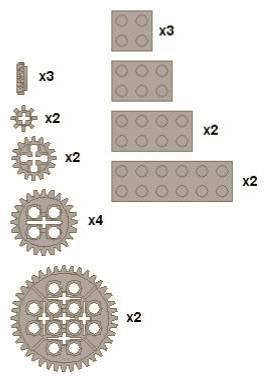

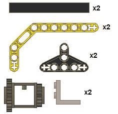

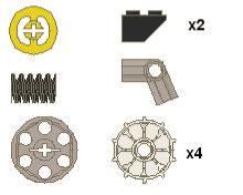
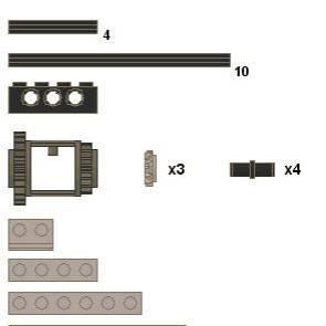
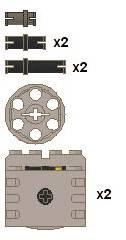
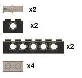
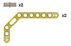
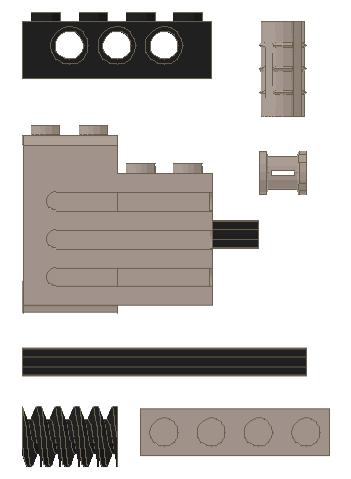
2 Catapult 18 Rope Lego Band Rubber Band


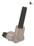
3 Catapult: Arm
4 Catapult: Arm

5 Catapult: Arm Leave the other end of the rubber band loose for now

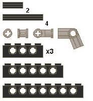
6 Catapult: Right Side

7 Catapult: Right Side

8 Catapult: Right Side


9 Catapult: Right Side

10 Catapult: Right Side


11 Catapult: Right Side

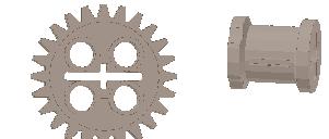
12 Catapult: Left Side


13 Catapult: Left Side

14 Catapult: Left Side


15 Catapult: Left Side


16 Catapult: Left Side


17 Catapult: Left Side

18 Catapult: Left Side


19 Catapult: Left Side Note: Wire should be at 4-6 long. Leave the other end loose for now.

20 Catapult: Left Side

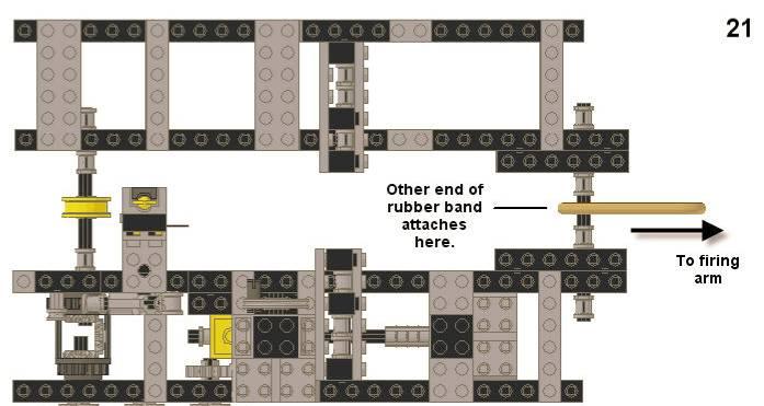
21 Catapult: Left Side


22 Catapult: Left Side

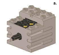
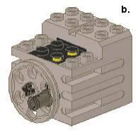
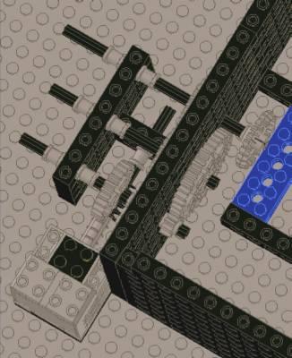
23 Catapult: Assembly


24 Catapult: Assembly

25 Catapult: Ammo Loader

26 Catapult: Ammo Loader 24

27 Catapult: Ammo Loader

28 Catapult: Ammo Loader

29 Catapult: Ammo Loader

30 Catapult: Ammo Loader


31 Catapult: Ammo Loader

32 Catapult: Ammo Loader

33 Catapult: Ammo Loader

34 Catapult: Ammo Loader 33


35 Catapult: Ammo Loader

36 Catapult: Ammo Loader These arms will connect the ammo loader to the rest of the catapult.


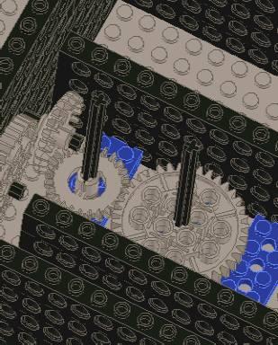
37 Catapult: Assembly 36 Insert the axles from the arms of the ammo loader into the green bricks on the back of the catapult


38 Catapult: Assembly The final pin to attach the ammo loader goes through the last hole on the catapult just below the smooth plates to the hole on the ammo loader just below the sloped brick. When connected and secured on each end with a bushing, the ammo loader will be at an angle to the rest of the catapult.


39 Catapult: Assembly 38 Side view Bottom view


40 Catapult: Assembly Lego rubber bands Note: When the motor is in the position above, the lever arm should be locked into the differential gear. When the motor is turned halfway, the lever should be free from the differential. If this is not the case, readjust the bands.

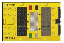
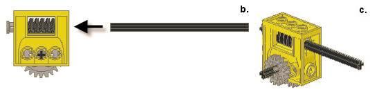
41 Catapult: Wiring Wiring Guide Port 1 connects to the touch sensor under the arm. Port 3 connects to the touch sensor on the rcx. Port A connects to the motor on the front of the catapult. Port B connects to the motor on the ammo loader Port C connects to the motor on the middle of the catapult

42 Catapult: Assembly string The sting is tied at one end to the angled arm and at the other end to the yellow cylinder.


43 Catapult: Assembly 42 These white wheels will serve as the ammo, they slide into the loader as shown.


44 Catapult: Final Notes 1. Make sure that when the arm is pulled down, the sloped brick hits the touch sensor The gears on the ammo loader work best if they are in the position shown. How it works: When the program below is run, the firing arm will wind down until touch sensor 1 is pressed. Then, motor A will stop and a single white wheel will be moved from the loader onto the arm. When touch sensor 2 is pressed, motor C will move. This will pull the firing lever, and release the arm. The catapult will then reload itself automatically.

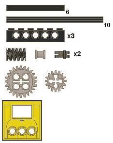
45 Building a Music Box


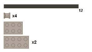
46 Building a Music Box BOX x38 x3 x2 x4 x2 x21 x21 x2 x4 7 x5 x17 x4 x4 x3 x3 x4 x2 48x48 plate x3 x4 8 x4 x4 10 x3 12


47 Building a Music Box x16 1 x17 x17 48X48 plate 2


48 Building a Music Box x2 3 x4 x2 4


49 Building a Music Box x2 5 6

50 Building a Music Box x4 7


51 Building a Music Box 8 10 x2 12 x3 9


52 Building a Music Box 10 x2 x4 2 views


53 Building a Music Box 11 x x2 x2

54 Building a Music Box 13 14


55 Building a Music Box 15 x4 16


56 Building a Music Box 17 x2 x2 18

57 Building a Music Box 19 x2 Note: From this point, you can build one of two tops. The first top will just open and the second top is motorized to open when the music box has been cranked.


58 TOP #1 Building a Music Box x10 x36 x22


59 Building a Music Box 20 x36 x20 21


60 Building a Music Box x10 22
LEGO 2D Planar Manipulator (with zero offset between Z1 and Z2 axes of rotation)
") LEGO 2D Planar Manipulator (with zero offset between Z1 and Z2 axes of rotation) Uses some parts not found in NXT Mindstorms Kit 9797 e.g. 2 nd Turntable, 1x12 plates, and 15100: Pin-hole Friction Peg.
LEGO 2D Planar Manipulator (with zero offset between Z1 and Z2 axes of rotation) Uses some parts not found in NXT Mindstorms Kit 9797 e.g. 2 nd Turntable, 1x12 plates, and 15100: Pin-hole Friction Peg.
The Wheels Module The Seats Module Integrate the seats and Wheels modules Ferris Wheel base Build the Gear System...
 Alternate Motorization Kit The Wheels Module... 2 The Seats Module... 3 Integrate the seats and Wheels modules... 4 Ferris Wheel base... 5 Build the Gear System... 7 Ferris Wheel Final Integration!!!...
The Nomenclature and Geometry of LEGO
 The Nomenclature and Geometry of LEGO AN OVERVIEW OF LEGO EV3 MINDSTORMS ELEMENTS AND HOW THEY WORK TOGETHER UPDATED 9/27/2015 Required Stuff Please do not wander the building. Rest Rooms Location. Food
ORTOP Modular Robot v3.0 Arm Assembly
 Base Plate Assembly Parts Needed: Arm Assembly BAG 1 2 Socket Head Cap Screw, 1-1/4" 2 Socket Head Cap Screw, 1/2" 2 Button Head Cap Screw, 3/8" 6 Nuts 1 Gear Hub Spacer 1 Flat Building Plate 1 Single
Team #3691 FLL Technical Manual. Ashburn Robotics NXTreme (Team#3691)
") FLL 2010-11 Team #3691 http://www.ashburnrobotics.com/ TechManual NXTreme 3691 - FLL 2010-11.doc Body Forward Page 1 of 44 TechManual NXTreme 3691 - FLL 2010-11.doc Body Forward Page 2 of 44 Ashburn Robotics
FLL 2010-11 Team #3691 http://www.ashburnrobotics.com/ TechManual NXTreme 3691 - FLL 2010-11.doc Body Forward Page 1 of 44 TechManual NXTreme 3691 - FLL 2010-11.doc Body Forward Page 2 of 44 Ashburn Robotics
Wind Pump Construction
 What Will You Need? Page 1 The following components can be found in your kit, and are needed to build one wind pump: 50 Tooth Gear* 40 Tooth Gear* 20 Tooth Gear* 10 Tooth Gear* Wheel Hub 300mm (~12in)
the complete parts reference bricks
 the complete parts reference Here s a detailed overview of all the pieces in your LEGO BOOST kit. You can also identify LEGO elements precisely by their LEGO ID, which is printed on the LEGO BOOST test
Replacing the Reciprocator on the SWF Compact Series Machine (601C and 1201C)
") Follow the instructions below to replace the reciprocator in the SWF Compact series machines. The tools required can be found in the tool kit that came with the machine. Preparation 1. First, place the
Follow the instructions below to replace the reciprocator in the SWF Compact series machines. The tools required can be found in the tool kit that came with the machine. Preparation 1. First, place the
Desktop Trebuchet Kit Assembly Instructions
 Desktop Trebuchet Kit Assembly Instructions Contents of package (drawings are not to scale for clarity, parts that have duplicates are indicated with total number of that part to be found, example: 2X
Deriving Consistency from LEGOs
 Deriving Consistency from LEGOs What we have learned in 6 years of FLL and 7 years of Lego Robotics by Austin and Travis Schuh 1 2006 Austin and Travis Schuh, all rights reserved Objectives Basic Building
Instruction Manual. Manual Furniture Mover. Note: Owner/Operator must read and understand this instruction manual before using the furniture mover.
 Instruction Manual Manual Furniture Mover Note: Owner/Operator must read and understand this instruction manual before using the furniture mover. I - Contents 1. Application 2 Specifications 3.Assembly
ITEM NO. PART NO DESCRIPTION QTY.
 PUMP MAINTENANCE ITEM NO. PART NO DESCRIPTION QTY. 1 52002 Center Case 1 2 52052 Back End Plate 1 3 52051 Front End Plate 1 4 55090 Octagonal Nut 1 5 53001 Idler Gear 1 6 53002 Drive Gear 1 7 28062 Bushing
SERVICE MANUAL MODEL: 13512, 14412, 15312
 SERVICE MANUAL MODEL: 13512, 14412, 15312 CONTENTS TROUBLESHOOTING... 1-3 SERVICE ACCESS (1) FACE COVER, BELT COVER... 4 SERVICE ACCESS (2) BASE PLATE... 5 SERVICE ACCESS (3) FRONT COVER... 6 SERVICE ACCESS
SERVICE MANUAL AND PARTSLIST
 SERVICE MANUAL AND PARTSLIST Next 20 CONTENTS WHAT TO DO WHEN... 1~3 SERVICE ACCESS FACE COVER... 4 TOP COVER... 4 BASE COVER... 5 REAR COVER... 6 FRONT COVER... 7 MECHANICAL ADJUSTMENT NEEDLE THREAD TENSION...
FLL Coaches Clinic Chassis and Attachments. Patrick R. Michaud
 FLL Coaches Clinic Chassis and Attachments Patrick R. Michaud pmichaud@pobox.com Erik Jonsson School of Engineering and Computer Science University of Texas at Dallas September 23, 2017 Presentation Outline
Parts of a Lego RCX Robot
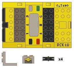
 Parts of a Lego RCX Robot RCX / Brain A B C The red button turns the RCX on and off. The green button starts and stops programs. The grey button switches between 5 programs, indicated as 1-5 on right side
25-200H. 12 Planer / Jointer. with Helical Cutterhead. Parts List.
 25-200H 12 Planer / Jointer with Helical Cutterhead 4001824 Parts List www.rikontools.com CABINET ASSEMBLY PARTS EXPLOSION & PARTS LIST KEY NO. DESCRIPTION KEY NO. DESCRIPTION 1 Pan Head Screw M6x12 P25-200H-1
Sole Fitness E95 Elliptical Trainer TurnKey Delivery and Setup Training
 Sole Fitness E95 Elliptical Trainer TurnKey Delivery and Setup Training Delivery Requirements Ground delivery Inside delivery to customer-specified location Unpack and assemble machine, and remove packing
The Challenge. What to Do
 LEGO Protractor The Challenge How can you accurately measure an angle? Create your own protractor using a rotation sensor and gears. Do this protractor activity first, then try the Slingshot or Peripheral
Daily Maintenance. 2. Insert bobbin cases in to rotary hooks. Make sure bobbin thread is not over 2 inches long. Close bobbin case covers.
 Rotary hook 1. Open bobbin case covers and remove bobbin cases. Use brush to remove lint build up in and around rotary hooks. Compressed air may also be used. Daily Maintenance Cle aning Oiling Rotary
Nebraska 4-H Robotics and GPS/GIS and SPIRIT Robotics Projects
 Name: Club or School: Robots Knowledge Survey (Pre) Multiple Choice: For each of the following questions, circle the letter of the answer that best answers the question. 1. A robot must be in order to
AlphaBot Assembly Diagram
 AlphaBot Assembly Diagram Part 1:AlphaBot baseboard assembly 1 Fix the motors onto the AlphaBot baseboard with the brackets, and then use (C) and (F) to install the encoder disks. 2 Fix the Infrared sensors
Sound Automata. Category: Physics: Force & Motion; Sound & Waves. Type: Make & Take. Rough Parts List: Tools List: Video:
 Sound Automata Category: Physics: Force & Motion; Sound & Waves Type: Make & Take Rough Parts List: 2 Clear plastic cups, large 2 Bamboo skewers 2 Straws 1 Sheet of cardboard or foam core 1 Bottle cap
The light sensor, rotation sensor, and motors may all be monitored using the view function on the RCX.
 Review the following material on sensors. Discuss how you might use each of these sensors. When you have completed reading through this material, build a robot of your choosing that has 2 motors (connected
FBX-PA-2AC. Third edition : April No
 FBX-PA-2AC Third edition : April 2006 No. 060058 INTRODUCTION Thank you very much for purchasing Kansai Special FBX series. Read and study this Instruction Manual carefully before you start any of the
BY ALIEN TECHNOLOGIES CORP
 BY ALIEN TECHNOLOGIES CORP Assembly Instructions TopLift Pros YOU MAY ALSO REVIEW OUR ASSEMBLY VIDEO, PLAY AND PAUSE AT YOUR CONVENIENCE. JUST VISIT US AT WWW.TOPLIFTPROS.COM AND GO TO Customer Support
Spare Parts. Contents. Contents Contents
 Spare Parts 2013 Spare Parts Contents Contents Contents LEGO Education StoryStarter 3 LEGO Education WeDo 4 Machines and Mechanisms 5 LEGO MINDSTORMS Education 6-8 TETRIX by Pitsco 9-16 LEGOeducation.us
SLED Frame Service Guide
 SLED Frame Service Guide Tools Needed: 10, 8, 6, 5 & 3mm Allen Keys Torque Wrench Press fit Headset or BB Press Loctite 638 BEARING RETAINER!! (Very Important) 2-Arm Gear Puller Crown race puller SLED
Motorized or Crank Operated Fortress Zipper Track Shade with Housing and Side Track Installation Instructions
 Motorized or Crank Operated Fortress Zipper Track Shade with Housing and Side Track Installation Instructions Tools Needed Drill 3/8 Metal Drill Bit ¼ Masonry Drill Bit Measuring Tape Pencil 4 Level Phillips
MODEL 1703E THE CHAMBERLAIN ARM TM INSTALLATION INSTRUCTIONS To be used in conjunction with the Lift-Master Garage Door Operator Owner's Manual
 MODEL 1703E THE CHAMBERLAIN ARM TM INSTALLATION INSTRUCTIONS To be used in conjunction with the Lift-Master Garage Operator Owner's Before you begin, please read this ENTIRE instruction manual. One- Piece
XI. Rotary Attachment Setups
 XI. Rotary Attachment Setups 1) Turn off the laser. 2) Put the rotary attachment onto the engraving table. Ensure the two screw holes on right side of rotary attachment match the two corresponding holes
Installation instructions for FC9 & FC18 Forward Controls for Yamaha V-Max
 Installation instructions for FC9 & FC18 Forward Controls for 1985-2007 Yamaha V-Max It is highly recommended that you use a thread lock compound such as Loctite brand on all threads to keep them from
Replacing the Reciprocator on an SWF Multi-head.
 Replacing the Reciprocator on an SWF Multi-head. Follow the instructions below to replace the reciprocator in the SWF multi-head machines. The tools required are found in the tool kit that came with the
Easy Engineering Guide
 Index: Unleash Your Creativity! Page 1: The Basics Page 2: Sorting Dowels Page 3: Measuring and Cutting Page 4: Dowels and Holes (Reaming Holes) Page 5: Reaming, Screws, Slide-Stop Material Page 6: Hydraulics/Pneumatics
(Making work easier phew!)
") (Making work easier phew!) Simple Machines Foldable Use the directions to complete your foldable. Then flip to the back to finish your notes. What are MACHINES? Most people think of complex, technical,
(Making work easier phew!) Simple Machines Foldable Use the directions to complete your foldable. Then flip to the back to finish your notes. What are MACHINES? Most people think of complex, technical,
S A F T E Y W A R N I N G
 BINDING CUTTING BASE This tool is designed to fit on a Porter Cable Model 310 and 3701 trim router, this combination will provide you with an easy way to accurately cut a binding rabbet on you instrument.
Installation Instructions
 for s TOC Table of Contents 1 Mortise Lock Handing Instructions.... 2 2 3 4 5 Mortise Lock Door Preparation & Installation... 3 HSS Trim Installation.... 5 Knob x Knob...6 Lever x Knob....7 Turn-Piece
SERVICE MANUAL PARTS LIST MODEL: NH40
 SERVICE MANUAL & PARTS LIST MODEL: NH40 CONTENTS What to do when... 1-3 SERVICE ACCESS Face Cover... 4 Bed Cover... 5 Free-arm Cover... 6 Front Cover... 7 Rear Cover... 8 MECHANICAL ADJUSTMENT Presser
1) Place the reactor stand on a sturdy bench with the bottom plate facing toward the front.
 Place the reactor stand on a sturdy bench with the bottom plate facing toward the front.") Assembly Instructions for ChemRxnHub Reactor Systems 1) Place the reactor stand on a sturdy bench with the bottom plate facing toward the front. Loosen knobs on the right and left using 2 hands of the
Assembly Instructions for ChemRxnHub Reactor Systems 1) Place the reactor stand on a sturdy bench with the bottom plate facing toward the front. Loosen knobs on the right and left using 2 hands of the
INSTRUCTIONS FOR HIT TEMPLATE FOR ALARM LOCK DL3500 MORTISE LOCK
 1825 VIA BURTON ANAHEIM CA 92806 714-772-5202 / FAX 714-772-2302 EMAIL: MAIL@MAJORMFG.COM WEB: WWW.MAJORMFG.COM INSTRUCTIONS FOR HIT-66-210 TEMPLATE FOR ALARM LOCK DL3500 MORTISE LOCK WHEN USING POWER
CONTENTS LOCATE AND IDENTIFY THE PARTS... WIND THE BOBBIN... PREPARE YOUR TOP THREAD... STITCH SELECTOR / STITCH LENGTH/STITCH WIDTH CONTROLS...
 SERVICE MANUAL SEWING MACHINE MODEL 385. 15208400 OCTOBER, 2003 CONTENTS LOCATE AND IDENTIFY THE PARTS... WIND THE BOBBIN... PREPARE YOUR TOP THREAD... STITCH SELECTOR / STITCH LENGTH/STITCH WIDTH CONTROLS...
Worksheet Answer Key: Tree Measurer Projects > Tree Measurer
 Worksheet Answer Key: Tree Measurer Projects > Tree Measurer Maroon = exact answers Magenta = sample answers Construct: Test Questions: Caliper Reading Reading #1 Reading #2 1492 1236 1. Subtract to find
JVice Care and Maintenance Thanks for purchasing a Jvice. If properly looked after your Jvice will give a lifetime of tying pleasure.
 JVice Care and Maintenance Thanks for purchasing a Jvice. If properly looked after your Jvice will give a lifetime of tying pleasure. Although it is manufactured from highest quality materials any metal
HANDWHEEL ASSEMBLY UPGRADE
 HANDWHEEL ASSEMBLY UPGRADE PURPOSE The purpose of the notice is to document the procedures involved in removing old handwheel assembly parts and replacing them with new parts. The new parts allow the handwheel
LEGO Mindstorms Class: Lesson 1
 LEGO Mindstorms Class: Lesson 1 Some Important LEGO Mindstorm Parts Brick Ultrasonic Sensor Light Sensor Touch Sensor Color Sensor Motor Gears Axle Straight Beam Angled Beam Cable 1 The NXT-G Programming
Lab book. Exploring Robotics (CORC3303)
") Lab book Exploring Robotics (CORC3303) Dept of Computer and Information Science Brooklyn College of the City University of New York updated: Fall 2011 / Professor Elizabeth Sklar UNIT A Lab, part 1 : Robot
Lab book Exploring Robotics (CORC3303) Dept of Computer and Information Science Brooklyn College of the City University of New York updated: Fall 2011 / Professor Elizabeth Sklar UNIT A Lab, part 1 : Robot
SECTION 9: PARTS. Table Breakdown REF PART # DESCRIPTION REF PART # DESCRIPTION
 SECTION 9: PARTS Table Breakdown 1 2 3 4 5 6 7 8 9 10 11 12 13 14 15 16 17 18 19 20 21 22 23 24 23 25 17 26 27 8 1 P0675001 CAP SCREW M8-1.25 X 30 15 P0675015 SUPPORT BLOCK 2 P0675002 TABLE SUPPORT BLOCK
Dream Fabric Frame Assembly Instructions
 Dream Fabric Frame Assembly Instructions Copyright January 1, 2016 Jim M. Bagley, GraceWood, Inc (Reproduction Prohibited) Version 2.4 Table Of Contents Parts List 3 Step 1: Table Set Up 6 Step 2: Install
Rhino Packing Gland Tool
 Instruction Sheet P/N Rhino Packing Gland Tool 1. Description See Figure 1. The Rhino packing gland tool is used to remove the packing gland from Rhino bulk unloader pumps. The tool consists of two components,
Standard Operating Procedure
 RIT MULTIDISCIPLINARY SENIOR DESIGN 2010 Standard Operating Procedure Baja Water Propulsion Test Stand This SOP specifies how to assemble, use, troubleshoot, and disassemble the water propulsion system
Catapult Engineering
 With support from Oxfordshire County Council, Science Oxford is pleased to present; Catapult Engineering The Physics of Siege Weapons STEM Club Resource Pack Introduction: Catapult engineering involves
TABLE OF CONTENTS. Sample file. Projects 25 Worksheets & Quizzes 28 Coloring Pages 32 Mazes 48 Links 52 Answer Keys 56
 TABLE OF CONTENTS Simple Machines 3 Inclined Plane 5 Lever 8 Pulley 10 Wedge 12 Wheel & Axle 14 Gear 15 Compound Machines 17 Handwriting/Spelling Practice 18 Print 18 Manuscript/D'Nealian-style 20 Cursive
SERVICING MANUAL 419S/423S
 SERVICING MANUAL 415 419S/423S TROUBLESHOOTING PROBLEM CAUSE REMEDY REFERENCE 1. SKIPPING 1. NEEDLE IS NOT INSERTED INSERT THE NEEDLE PROPERLY. STITCHES PROPERLY. 2. NEEDLE IS BENT OR WORN. CHANGE THE
BE1151 Precision Priming Press Instructions
 BE1151 Precision Priming Press Instructions Tech Support: (360) 676-3299 Email: service@bullets.com Web: www.bullets.com Shell Holder Not Included. Introduction The Model BE1151 is designed to be the ultimate
1 of 2 3/3/2017 4:49 PM
 1 of 2 3/3/2017 4:49 PM Front Door Window, Assembly Overview 1 - Window guide - Inserted on flange 2 - Door 3 - Inner window recess seal - Inserted on flange 4 - Bolt - 20 Nm 5 - Carrier assembly - Window
CrossOver X25 Lock Installation Need another copy of these installation sheets? You can download one at
 CrossOver X25 Lock Installation Need another copy of these installation sheets? You can download one at www.crossoverlock.com/supportcenter.htm 1 Back view of installation Major lock parts 1. Rear handle
BombiniBot Parts and Assembly
 BombiniBot Parts and Assembly Copyright 05 mindsensors.com / Parts Loose Parts: Part Quantity Tire Motor Mount 4-Wire Encoder Cable Encoder Wheel Velcro Strip Top Chasis Plate Bottom Chasis Plate Battery
SERVICE MANUAL & PARTS LIST MODEL: MC400E
 First Edition: February SERVICE MANUAL & PARTS LIST MODEL: MC00E PARTS LIST MODEL: MC00E 0 0 MODEL: MC00E KEY PARTS NO. NO. DESCRIPTION 0 0 0B0 000 0A0 0A0 000 000 0 000 0 0000 0000 000 00 0 0 00 A0 0B0
WOLF PUP LOOM TM & WOLF PUP LT LOOM TM
 WOLF PUP LOOM TM & WOLF PUP LT LOOM TM Assembly Instructions FL3000 FL3006 FL3009 WOLF PUP WOLF PUP LT Find out more at schachtspindle.com Schacht Spindle Company 6101 Ben Place Boulder, CO 80301 p. 303.442.3212
Dream Fabric Frame Assembly Instructions
 Dream Fabric Frame Assembly Instructions Copyright May 01, 2015 Jim M. Bagley, GraceWood, Inc (Reproduction Prohibited) Version 1 Table Of Contents Parts List 3 Step 1: Table Set Up 6 Step 2: Install the
8.0 RE-CALIBRATION OF SPACE
 8.0 RE-CALIBRATION OF SPACE 101 ATTENTION: PLEASE READ BEFORE PROCEEDING. RE-CALIBRATION OF SPACE NO RE-ADJUSTMENT of space is required when changing from one code card to another. The space indicator
This is a motor attachment option in which the motors attach closely to the sides of the NXT.
 6 II. Ways to Attach NXT Motors 1. Simple Side Attachment Model Description: This is a motor attachment option in which the motors attach closely to the sides of the NXT. 7 These are the parts that you
RULTRACT RETRACTOR CABLE REPLACEMENT INSTRUCTIONS. Rultract, Inc. is the ONLY authorized service center in the U.S.A.
 RULTRACT RETRACTOR CABLE REPLACEMENT INSTRUCTIONS Rultract, Inc. is the ONLY authorized service center in the U.S.A. When your Rultract instrument needs repair or service, contact Rultract Inc. or Rultract
Model 20: Home & Garden Cart
 Model 20: Home & Garden Cart Parts List Step 1: A: Install two ¾ Bolts (C) through the rear trim piece on the Bottom Panel (S) and attach to Lock Nuts. (Lock nuts on bottom side) B: Place left Side Panel
3.2.3 Rear Door Window and Quarter Window Carrier Assembly
 Tighten all bolts. Tighten bolts marked -1- and -2- in specified sequence. Tightening torque: 8 Nm Remaining bolts can be tightened in any sequence. Insert door window -3- through window recess without
A59 APD & A86 CPD 5'X 16' SW ALUMINUM PORTA-DOCK
 Page 1 of 5 PORTA-DOCK, INC. A59 APD & A86 CPD 5'X 16' SW ALUMINUM PORTA-DOCK *For Beige Decking Add the Letter B to model* Thank you for purchasing our product! *Please read these instructions and follow
PRE-VISIT ACTIVITIES
 PRE-VISIT ACTIVITIES Two pieces of paper Scissors FOR SIMPLE MACHINES FIELD TRIP WEDGE A wedge is an inclined plane that is thick at one end and tapers to a point on the other, often used to separate things.
S-85SCH
 4411-4423-4432-4443-4452 5511-5523-5532-5554 44S-85SCH Service Manual 104 73 14-26 2014-02-24 CONTENTS 1. Names of principal parts...2 2. Removing methods of external parts 2-1 Sewing table...3 2-2 Face
Greenhouse Assembly Instructions
 Greenhouse Assembly Instructions Our Help Line provides support and advice to customers of Summer Garden Buildings after ordering. For advice before you buy you can phone us free 7 days a week on 0800
Depending on the size you ordered you will have either 5 Foot sections which will build the 10 Foot frame or 6 Foot sections which will build the 12
 XL Quilting Frame 1 Depending on the size you ordered you will have either 5 Foot sections which will build the 10 Foot frame or 6 Foot sections which will build the 12 Foot frame Printed 2 June 2014 Updated
Deck Mount Installation with Bench
 Deck Mount Installation with Bench 1. Mark track with square. 2. Cut tracks with saw. 3. Drill ¼ hole (if needed.) 4. Countersink track. 5. Countersink all track 6. File all track ends. ends. 7. Lay out
PoeBot Building Instructions CCISD. Upper Gripper. Lower Gripper/ Spatula. PoeBot Instructions PLTW. Clear Creek ISD
 Upper Gripper Lower Gripper/ Spatula PoeBot Instructions PLTW Clear Creek ISD 1. Chasis Construction (Split Group with half starting Step 1 and half starting Step 13.) Note: These flat bearings are offset
SERVICE PARTS LIST PAGE 1 OF 6 BASE ASSEMBLY SPECIFY CATALOG NO. AND SERIAL NO. WHEN ORDERING PARTS 12" SLIDING COMPOUND MITER SAW
 PAGE 1 OF 6 BASE ASSEMBLY 00 0 CATALOG NO. EXAMPLE: SPECIFY CATALOG NO. AND NO. WHEN ORDERING PARTS 6955-20 1 02-80-0050 Thrust Bearing (1) 2 05-80-0510 M5 x 12mm Flat Head T-20 Screw (5) 3 05-81-0135
The Archer Bow Press OPERATING INSTRUCTIONS Partridge Woods Elk Rapids, MI
 The Archer Bow Press OPERATING INSTRUCTIONS 8203 Partridge Woods Elk Rapids, MI 49629 www.bowforcearchery.com 1 MAINTENANCE AND FINE TUNING Horizontal Pulling Bar The Horizontal Pulling Bar has a break-in
ASSEMBLY INSTRUCTIONS MANUAL
 PAGE 1 OF 9 RECOMMENDED TOOLS FOR ASSEMBLY: ALLEN WRENCH (INCLUDED) BOX WRENCH (INCLUDED) PHILLIPS SCREW DRIVER (NOT INCLUDED) PARTS IN CARTON: ALLEN WRENCH SCREWS (20 EACH) ROUND HEAD SCREWS (8 EACH)
INSTRUCTIONS FOR HIT LOCK MORTISER
 1825 VIA BURTON ANAHEIM CA 92806 714-772-5202 / FAX 714-772-2302 EMAIL: MAIL@MAJORMFG.COM WEB: WWW.MAJORMFG.COM INSTRUCTIONS FOR HIT-66-200 LOCK MORTISER WHEN USING POWER TOOLS ALWAYS WEAR EYE AND EAR
Thank you for purchasing out product! *Please read these instructions and follow them step by step. *
 Page 1 of 7 AD17 AA DS 4 X 16 T12 Thank you for purchasing out product! *Please read these instructions and follow them step by step. * STEP 1. Slide two support posts (REF. # 24) into the two outside
SERIES I MILLING MACHINES
 INSTALLATION, OPERATION, MAINTENANCE, AND PARTS LIST SERIES I MILLING MACHINES TP5260 Revised: August 29, 2005 Manual No. M-450 Litho in U.S.A. Part No. M -0009500-0450 June, 2003 MAINTENANCE PROCEDURES
ELECTRIC RACER BASIC BUILD
 Page 1 Name: Set: Date: This guide will take you through the process of creating a basic electric racer. After you finish this build, you should be able to experiment, design and engineer your own racer.
SAFETY INSTRUCTIONS. Wear protective clothing, including safety glasses and steel toe boots.
 SAFETY INSTRUCTIONS Wear protective clothing, including safety glasses and steel toe boots. DO NOT allow loose clothing or long hair near machine operations. Keep work site and machine clean. Use brush
VIEWPOINT ALUMINUM RUNNING BOARD TOYOTA RAV4
 PARTS LIST: VIEWPOINT ALUMINUM RUNNING BOARD 1 Driver/Left Running Board 4 10-1.5mm x 50mm T-Bolt 1 Passenger/Right Running Board 12 10mm Plastic Retainers 1 Driver/Left Bracket 2 10-1.50mm x 40mm Hex
LANDING GEAR. 1. Fit landing gear into slots on bottom of fuselage.
 LANDING GEAR 1. Fit landing gear into slots on bottom of fuselage. 4. Use channel-lock pliers to press blind nuts into position (note: drilled hole should be slightly smaller than shaft of blind nut for
Assembly Instructions for Laser Sailboat Dolly (with Beach Wheels for 1 Axle & Ramp Wheels with Reversible Axle)
") Assembly Instructions for Laser Sailboat Dolly (with Beach Wheels for 1 Axle & Ramp Wheels with Reversible Axle)! IMPORTANT: Before you begin, please read these instructions and check to be sure that all
Assembly Instructions for Laser Sailboat Dolly (with Beach Wheels for 1 Axle & Ramp Wheels with Reversible Axle)! IMPORTANT: Before you begin, please read these instructions and check to be sure that all
PARTS LIST MODEL DC4100
 MODEL DC0 0 0 MODEL DC 0 KEY 0 0 PARTS 00 000 00000 000 00 0000 00000 000 00 0000 000 00 000 00000 000 000 000 000 000 0 00000 0 0000 0 0000 000 0000 00 00000 0000 0 0000 00000 00 00 00000 00000 0000 DESCRIPTION
Q-Zone Hoop-Frame. Assembly Instructions. Copyright July 11, 2018 Grace Company (Reproduction Prohibited) Version 1.8
 Version 1.8") Q-Zone Hoop-Frame Assembly Instructions Copyright July 11, 2018 Grace Company (Reproduction Prohibited) Version 1.8 Table of Contents Table of Contents... i Warranty... ii Parts List Box 1...iii Box 2...
Q-Zone Hoop-Frame Assembly Instructions Copyright July 11, 2018 Grace Company (Reproduction Prohibited) Version 1.8 Table of Contents Table of Contents... i Warranty... ii Parts List Box 1...iii Box 2...
Maintenance manual. 1. Check height seat adjusment
 1. Check height seat adjusment 1.1 By control hand lever seat, seat must always going down when person is sitting on it. 1.2 Squeaky noise when control hand lever seat? 1.1 1.2 2. Check table height adjustment
Installing Your Electronic Deadbolt
 Ultra Security Plus Electronic Deadbolt Installation Instructions http://www.hberger.com/video-gallery/electronic-deadbolt New Installation Lock Location Preparation (Skip this section if you door has
Door window. Front door window, assembly overview
 64-50 Door window Front door window, assembly overview 1 - Window channel Pushed onto flange 2 - Door window Removing Page 64-52 Adjusting Page 64-53 3 - Door 4 - Outer window channel Pushed onto flange
Assembly Guide Robokits India
 Robotic Arm 5 DOF Assembly Guide Robokits India info@robokits.co.in Robokits World http://www.robokitsworld.com http://www.robokitsworld.com Page 1 Overview : 5 DOF Robotic Arm from Robokits is a robotic
TROLLA LEAVY 97 CM Lawn sweeper
 TROLLA LEAVY 97 CM Lawn sweeper Artikel nr.: 1008 EN Operating manual 014/1 Dear Customer, Congratulations on your new Trolla product. We hope you will enjoy it. Checkout with your new Trolla product may
Tube-Line Baleliner 7800TX2
 Tube-Line Baleliner 7800TX2 Parts Manual 29667 (13/04/12) 2 3 Frame Assembly 4 Frame Assembly Item Qty Part # Description 1 1 27298 E-Stop Button 2 8 28663 Outside Rail Pin 3 1 28805 Wire Shield 4 1 28823
ELSTON. Gopher Getters. Parts List for GA-400 and GA-500 ELSTON MANUFACTURING INC. Please Contact Us for Parts and Service:
 ELSTON Gopher Getters Parts List for GA-00 and GA-00 Another Quality Product of: Please Contact Us for Parts and Service: ELSTON MANUFACTURING INC. 70 N Weber Sioux Falls, SD 70 www.elstonmfg.com -800-8-8
N. 15th Street, Middlesboro, KY FLIP TARP DUMP BODY INSTALLATION INSTRUCTIONS
 1-800-248-7717 1002 N. 15th Street, Middlesboro, KY 40965 FLIP TARP DUMP BODY INSTALLATION INSTRUCTIONS Congratulations on your purchase of a Mountain Flip Tarp Dump Body tarping system. With tarping systems
Crestline Dampening System. Installation Instructions. Hamada RS34 & VS34 Parent Unit DU34 Upper Unit. For Presses Originally Equipped With
 Crestline Dampening System Installation Instructions Hamada RS34 & VS34 Parent Unit DU34 Upper Unit For Presses Originally Equipped With Molleton Dampeners X88-78 01/2001 Rev-A GENERAL INFORMATION ATTENTION
Gardman Lean-to Greenhouse Assembly Instructions
 Page 1 Gardman Lean-to Greenhouse Assembly Instructions Our Help Line provides support and advice to customers of Summer Garden Buildings after ordering. For advice before you buy you can phone us free
Where C= circumference, π = 3.14, and D = diameter EV3 Distance. Developed by Joanna M. Skluzacek Wisconsin 4-H 2016 Page 1
 Instructor Guide Title: Distance the robot will travel based on wheel size Introduction Calculating the distance the robot will travel for each of the duration variables (rotations, degrees, seconds) can
Operating Manual. Belt band attachment. Version 1.0. Published by: ZSK Stickmaschinen GmbH - Dokumentation - D Krefeld-Bockum
 Operating Manual Belt band attachment Version 1.0 Published by: ZSK Stickmaschinen GmbH - Dokumentation - D-47800 Krefeld-Bockum Magdeburger Str. 38-40 99 by ZSK, Printed in Germany Contents Belt band
Operating Instructions
 Operating Instructions Cobra Percussion Drill & Windowless Sampler TABLE OF CONTENTS 1. STEP-BY-STEP GUIDE 2 1.1 Assembling the liner pre-loader 2 1.2 Loading the liner onto the liner pre-loader 2 1.3
FBX1104P FBX1104 FBX1106P FBX1106
 FBX1104P FBX1104 FBX1106P FBX1106 Second edition : September 2004 No. 040037 INTRODUCTION Thank you for your purchasing Kansai Special's FBX Series. Read and study this instruction manual carefully before
Astro-Physics Inc. 400QMD Lubrication/Maintenance Guide
 Astro-Physics Inc. 400QMD Lubrication/Maintenance Guide The following guidelines should be followed to lubricate the three main parts of the 400QMD mount. The QMD stands for Quartz Micro-Drive controller.