GENERAL DYNAMICS Electric Boat Division Groton, Connecticut. Phase I Report
|
|
|
- Bonnie Warner
- 5 years ago
- Views:
Transcription
1 GENERAL DYNAMICS Electric Boat Division Groton, Connecticut Phase I Report Evaluation OF AN AUTOMATIC SEAM TRACKING/ ADAPTIVE CONTROL WELDING SYSTEM FOR SHIPYARD APPLICATIONS Prepared by Neil D. Fichtelberg Department 341 Submitted to: SP-7 Welding Panel of the Ship Production Committee Society of Naval Architects and Marine Engineers In Fulfillment of Purchase Order No. POM R Reviewed by: R. W. Peirce, Chief Welding and Materials Engineering Approved by: EBDiv. Report No. PDE-262 February 1985
2 Report Documentation Page Form Approved OMB No Public reporting burden for the collection of information is estimated to average 1 hour per response, including the time for reviewing instructions, searching existing data sources, gathering and maintaining the data needed, and completing and reviewing the collection of information. Send comments regarding this burden estimate or any other aspect of this collection of information, including suggestions for reducing this burden, to Washington Headquarters Services, Directorate for Information Operations and Reports, 1215 Jefferson Davis Highway, Suite 1204, Arlington VA Respondents should be aware that notwithstanding any other provision of law, no person shall be subject to a penalty for failing to comply with a collection of information if it does not display a currently valid OMB control number. 1. REPORT DATE FEB REPORT TYPE N/A 3. DATES COVERED - 4. TITLE AND SUBTITLE Evaluation of An Automatic Seam Tracking/ Adaptive Control Welding System For Shipyard Applications a. CONTRACT NUMBER 5b. GRANT NUMBER 5c. PROGRAM ELEMENT NUMBER 6. AUTHOR(S) 5d. PROJECT NUMBER 5e. TASK NUMBER 5f. WORK UNIT NUMBER 7. PERFORMING ORGANIZATION NAME(S) AND ADDRESS(ES) Naval Surface Warfare Center CD Code Design Integration Tools Building 192 Room MacArthur Bldg Bethesda, MD PERFORMING ORGANIZATION REPORT NUMBER 9. SPONSORING/MONITORING AGENCY NAME(S) AND ADDRESS(ES) 10. SPONSOR/MONITOR S ACRONYM(S) 12. DISTRIBUTION/AVAILABILITY STATEMENT Approved for public release, distribution unlimited 13. SUPPLEMENTARY NOTES 14. ABSTRACT 15. SUBJECT TERMS 11. SPONSOR/MONITOR S REPORT NUMBER(S) 16. SECURITY CLASSIFICATION OF: 17. LIMITATION OF ABSTRACT SAR a. REPORT unclassified b. ABSTRACT unclassified c. THIS PAGE unclassified 18. NUMBER OF PAGES 81 19a. NAME OF RESPONSIBLE PERSON Standard Form 298 (Rev. 8-98) Prescribed by ANSI Std Z39-18
3 An automatic seem tracking/adaptive control welding system, the M-1OOO, was evaluated by weld testing using the vertical position high heat input pulsed gas metal arc welding process. During the course of the evaluation period, numerous hardware and software modifications were made by the machine designer/builder, CRC Automatic Welding, in response to Electric Boat Division suggestions. Significant improvements were made in bead shape and size, and in the automatic selection of the type of bead required and the parameters to use as a function of the prevailing groove geometry. It was concluded that the thru-the-arc concept of seem tracking/adaptive control used by the M-1OOO was a viable technology and potential savings in welding time may be possible if the M-1OOO could be made competitive with current mechanized systems in terms of weld quality and bead size deposited. However, additional development work, on both hardware and software, is required to realize the potential of the M-1OOO. i
4 TABLE OF CONTENTS Section , Abstract Introduction Objectives Approach CRC System Description (March 1983) Basic Operational Theory and Startup Procedure (March 1983) Summary of Expected Advantages of the M 1OOO Criteria for Evaluation of the M-1OOO Initial Evaluation: March 1983-December 1983 Less Serious Problems More Serious Problems M-1OOO Upgrade (December 1983 April 1984) Evaluation of Upgraded M-1OOO (December 1983-April 1984) Summary and Conclusions Recomnendat ions i ii
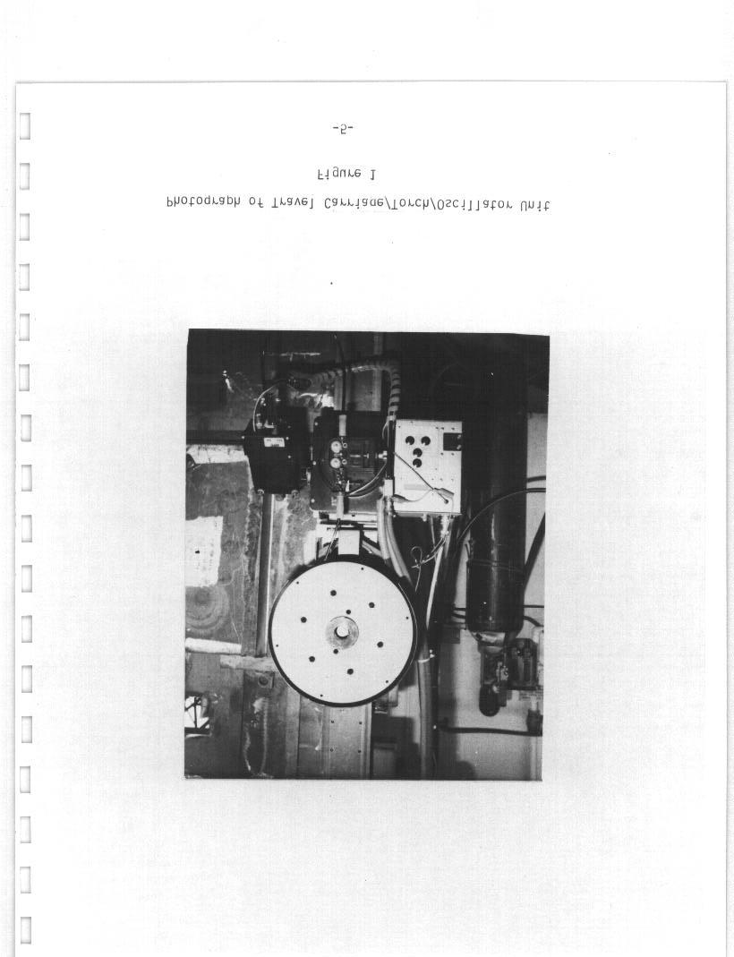
5 LIST OF FIGURES FIGURE NO Photograph of Travel Carriage/Torch/Oscillator Unit Startup Procedure and Single Bead Layer Modeling Routine (March 1983 ) Theory of Operation Routine for First Layer of Two Bead Fill Pass Layer Routine for Second Bead of Two Bead Fill Pass Layer or Either Bead of Two Bead Finish Layer With One Tracking Sidewall Routine for Single Bead Finish Layer With Automatic Tracking Finish Layer Bead-No Automatic Tracking Single Bead Layer Fill Pass Routine Welding Time Vs. Operator Factor for Three Wire Feed Speeds Welding Time Vs. Interpass Time for Two Wire Feed Speeds and Two Heat Inputs Photomacrograph of 1 in. Thick Weld PD Photomcrograph of Root Pass in 1 in. Thick Weld PD Photomascrograph of 1 in. Thick Weld No. 7 Illustration of Location of Modeling for Arc Restart and Area of Possible Lack of Fusion Upgraded M-1OOO Modeling Routine Photomacrograph of 1 in. Thick Weld PD Photomacrograph of 1 in. Thick Weld PD Photomacrograph of 1 in. Thick Weld PD Photograph of 1/4 in. Root Gap Test Weld Showing Effects of Slowing Dowm of Travel Speed We to Arc Riding Too High on Puddle PAGE i i i
6 FIGURE NO Photomacrograph of 1/4 in. Root Gap Test Weld Near Start Location Photomacrograph of 1/4 in. Root Gap Test Weld Near Stop Location Photomacrograph of 3/8 in. Root Gap Test Weld 40T Photomacrograph of 1/8 in. Root Gap Test Weld 41T Photomacrograph of 1/4 in. Root Gap Test Weld 42B Automatic Tracking Current/Voltage Trace Manual Tracking Current/Voltage Trace iv
7 LIST OF TABLES TABLE NO. PAGE I Heat Input Per Bead at Various Root Gaps 30 II Bead Patterns and Heat Inputs: Optimum Parameter and Heat Input-Manual Input Program V
8 FOREWORD This report presents the results of an evaluation and development project sponsored in part by the SP-7 Welding Panel, one of the panels of the Ship Production Committee of the Society of Naval Architects and Marine Engineers. The equipment was purchased by the Electric Boat Division of General Dynamics under a cost sharing program with the U.S. Maritime Administration managed by Newport News Shipbuilding and Drydock Company. The principal objective was to evaluate and develop the Crutcher Resources Corporation (CRC) M-1OOO Welding System for shipbuilding applications. The technical contributions and expertise of Messrs. Joseph H. Krause and David C. Main of Electric Boat Division are gratefully acknowledged. Acknowledgement is also made to the members of the SP-7 Welding Panel, to Mr. B. C. Howser, Newport News Shipbuilding, SP-7 Panel Chairman, and to M.I. Tanner, Newport News Shipbuilding, SP-7 Program Manager. In addition, the contributions of Crutcher Resources Corporation (CRC) Houston, Texas are acknowledged with special thanks to Floyd Thompson and his staff. vi
9 1.0 Introduction During the last decade, semi-automatic and mechanized welding processes have been developed for many shipyard applications including gas tungsten arc welding (GTAW) for orbital and horizontal rolled pipe welding, gas metal arc welding (GMAW) and flux cored arc welding (FCAW) for hull butts and seams, and submerged arc welding (SAW) for heavy section and Panel line applications. Use of such processes and equipment has resulted in increased deposition rates, improved quality, and a reduction in overall manhours. Existing systems, however, still require considerable operator control and intervention during the welding process, or the use of extensive fixturing. Inpendent control of the various welding parameters requires that the operator continually monitor the weld process and take rapid corrective action to assure consistent, controllable quality and high deposition rates. Poor joint fitup hinders the operator s ability to compensate for irregular joint conditions and taxes his ability to provide maximum arc-on time, resulting in less than optimum productivity. An automated welding system capable of detecting joint conditions and welding parameter deviations, and making corrective changes in real time, would alleviate the operator s on-going problems and provide higher operator efficiency and lower welding costs. In addition, welding times and quality may also be improved by the automatic selection of the optimum welding parameters and techniques for the prevailing joint conditions.
10 An automatic seam tracking/adaptive control welding system was first exhibited by CRC Automatic Welding at the American Welding Society Show in April This system, designated the M-1OOO, was primarily designed for the pipeline industry. However, it appeared to be adaptable to shipyard applications. Its unique features included: 1) automatic thru-the-arc seam tracking; 2) automatic selection of the optimum welding parameters based on prevailing joint conditions and pre-prograrmmed algorithms describing the welding technique; and 3) adaptive control of all welding parameters to make automatic, in process, real time corrections in welding parameters in response to changes in joint or underbead geometry. Added features provided for control of welding heat input and maintaining a constant bead fill height. Successful application of these features to shipbuilding may improve weld quality and operator factor. A CRC M-1OOO welding system was purchased under a cost sharing program between the U. S. Maritime Administration and the Electric Boat Division of General Dynamics. The principal objective was to evaluate and develop the M-1OOO system for shipbuilding applications. It soon became apparent that additional hardware and software development work would be required in order to accomplish pulsed gas metal arc welding using techniques representative of those used at Electric Boat. Because of the potential benefits to the shipyard, Electric Boat elected to fund the weldin g phases of this development under its Manufacturing and Production Engineering Program. CRC agreed to support this effort with internal work conducted by Electric Boat during 1983 this report. funding. and 1984 It is this development that is described in -2
11 2.0 Objectives The end objective of this program is to develop an automatic welding system suitable for shipyard use that reduces welding labor hours and if possible, support trade labor hours (such as grinding), without reducing weld quality, compared to mechanized equipment and techniques currently used. The objective of the current phase of this program is to evaluate and modify the CRC H-1OOO system to the point that it meets the end objective stated above for a limited shipyard application. 3.0 Approach An objective equipment evaluation necessitates the establishment of reasonable performance requirements based on currently used welding equipment and techniques. Additional requirements may also be necessary to insure that welding times are really reduced without manhour increases in associated trades, such as shipfitting and grinding. After establishment of the performance requirements, evaluation of the new equipment may be accomplished by welding plates designed to test one or more of the machine's capabilities. Analysis of the results and comparison with comparable information obtained with ship yard equipment and techniques forms the basis for equipment modification and re-evaluation. -3-
12 4.0 CRC System Description (March 1983). The CRC M-1OOO is an automatic, adaptive, closed-loop feedback welding system which automatically controls most welding parameters by thru-the-arc sensing. It is adaptable to the gas metal arc, submerged arc, and gas tungsten arc processes. The system consists Of carriage/torch/oscillator unit (Figure 1) and a an integrated travel microcomputer with keypad which would normally be located with the welding power supply. Communication between the two units is via a high speed serial line. Also located with the welding power supply is a smell box containing a current shunt and an external contactor. The only controls on the travel carriage are travel and wire feed jog switches, a travel forward/reverse switch, and a weld on/off switch. The torch, which is gas-cooled, uses a collet either a in. I. D. ceramic nozzle or to hold the contact tip. Gas cups 0.43 in. by 1.1 in. elongated aluminum nozzle, are screwed into the end of the torch barrel. A solenoid mounted on the bottom of the computer enclosure controls the supply of shielding gas to the torch. The microcomputer (8 bit RCA 1802 microprocessor) is responsible for almost the entire welding operation. This includes: selection of the initial welding parameters in accordance with preprogrammed data and algorithms describing the welding technique; sensing of joint sidewalls and underbead contour; adaptive control during the course of welding; display of information including welding parameters and joint profile information; detection of improper welding conditions; etc. -4-
13
14 5,0 Basic Operational Theory and Startup Procedure (March 1983) The M-1OOO system is designed to select the optimum initial welding parameters based on the joint geometry at the start location and make logical adjustments in tracking and welding parameters during the course of welding. The initial parameters are calculated by the computer based on preset data (such as wire diameter, shielding gas, and maximum heat input), pre-programmed algorithms describing the welding technique (such as the relationship between bead thickness and width, travel speed, and sidewall dwells), and the joint geometry. The joint geometry at the start location is determined by a modeling routine which involves touching the contact tip or the end of the filler wire extending from the contact tip to several locations within the joint groove and on the plate surface. The computer recognizes that contact has been made with the base metal because an electrical circuit is completed. These contact points define such things as location of the plate surface, depth of the groove remaining, and slope of the sidewalls. Figure 2 shows the details of one of several modeling routines and the startup procedure. Figure 3 presents a much simplified theory of operation. Using the model of the groove at the start location together with pre-programmed constants, algorithms describing the welding technique are accessed. The computer selects the optimum initial welding parameters and establishes a range of travel speeds to optimize the fill and welding efficiency without sacrificing weld quality. With the program used at Electric Boat, each bead was to be deposited with a constant thickness regardless of changes in joint geometry along its length. This is accomplished by varying the travel speed 6-
15 Turn weld on/off switch on. Torch rotates to preset lead/lag angle and 1ocates surface of workpiece. Torch retracts to preset contact tip to work distance. Wire is fed until it contacts plate surface, establishing initial electrode stickout. As torch moves over joint, operator turns off switch near center of joint. Operator turns on switch and torch lowers in. Locate inside wall. Locate outside wall. Compute and move to centerline. Locate bottom of joint. Retract torch in. Locate inside wall. Locate outs outside wall. Return to centerline, compute travel speed, oscillation dwells, etc., based on joint geometry. Strike arc. Adjust tracking and welding parameters sensing. by thru-the-arc StartuD Procedure and Single Bead Layer Modeling Routine (March 1983) Figure 2-7-


16 I 1 STRIKE ARC 7 I 1 I MAINTAIN CONTACT TIP TO WORK DISTANCE I ADAPTIVE CONTROL OF TRAVEL SPEED, DWELL TIMES, OSCILLATION SPEED, ETC., TO MAINTAIN CALCULATED FILL HEIGHT AND MOVING SPOT HEAT SIZE
17 in response to changes in groove width. However, restraints were imposed on maximum and minimum heat inputs to maximize the welding efficiency and keep. the heat input at or below the maximum allowed. After initiation of the arc, the initial pre-prograrmmed contact tip to work distance is maintained during the first four oscillation cycles. In addition, no sidewall tracking or adaptive control is performed. Centerline current and voltage samples are taken. These values are averaged and serve as a reference. Thereafter, sidewall tracking is accomplished by analyzing and processing current and voltage signals obtained during each sidewall dwell period extracted at signals, the and comparing it to reference amperage and voltage signals the center of each oscillation stroke. In response to these oscillation stroke inboard and outboard of center is adjusted. In more detail, a quantity called AC is computed based on the change in contact tip to work distance required to give a certain change in arc power at the sidewall, knowing the sidewall slope, wire diameter, etc. This empirical quantity controls, in effect, the depth of penetration into the sidewall. During each sidewall dwell period, the difference between the change in arc power over a distance near the centerline and the change in arc power as the arc approaches the sidewall is calculated and compared to AC. If the calculated value is less or greater than AC, then it indicates that the arc is not properly located with respect to the sidewall. If this occurs, then on the next oscillation stroke the torch will oscillate in. towards or away from the sidewall, as appropriate. If two successive corrections are made on one sidewall, no further corrections will be made, This is to prevent the possibility of the machine continuously widening the 9-
18 oscillation stroke in search of a sidewall that may not exist. In addition, CRC claimed that a minimum of in. of sidewall is required for automatic tracking, Therefore, if the sidewall height fell below in. during the course of welding, tracking on that sidewall would cease and no further changes in the extent of oscillation would occur. Torch to work distance is maintained by comparing the current and voltage sampled at the centerline on each oscillation stroke to the reference values taken during the first four oscillation cycles. An increase in torch to work distance, such as if the depth of the groove was suddenly increased as a result of metal excavation, or if the workpiece was moving away from the welding machine, would produce lower currents and higher arc voltages at the centerline compared to the reference values. This would result in the computer driving the torch in towards the weld until the centerline samples matched the During compensated oscillation reference values. the course of welding, variations in the joint width are for by the automatic tracking feature. The M-1OOO adjusts the stroke inboard and outboard of the centerline while still maintaining a constant sidewall penetration. In response to these width changes, the travel speed is adjusted, within the limits of the allowed heat input range, to maintain a constant bead thickness and bead shape. Other parameters, such as sidewall dwells and wire feed speed, may also be adaptively changed in response to the changes in bead width and travel speed. Average arc voltage is maintained through computer control of the power supply open circuit voltage. -10-
19 Ideally, no input should be required from the operator during the course of welding since the computer is performing automatic tracking and adaptively controlling all welding parameters. However, the operator has the ability to change the average arc voltage by using the keypad on the computer. This allows the operator some adjustment of the arc length to compensate for variations in wire coating, wire chemistry, contact tip condition, location of bead within groove, etc. The modeling routine presented in Figure 2 was designed for single bead layer fill passes, i.e., heads where two sidewalls of sufficient height are present. Four other routines were available to handle two bead fill layers and single and two bead finish layers. These routines are outlined in Figures 4,5,6 and 7. Figure 8 presents the single bead layer fill pass routine for comparison. Figure 4 shows the routine for a bead in a two bead fill pass layer. Automatic tracking is performed only on one sidewall; the width of oscillation is fixed and is dependent on the distance between points 5 and 6 in the figure. The routine in Figure 5 may be used for either bead of a two pass fill layer or either bead of a two pass finish pass layer. This routine is similar to that in Figure 4 except that a lower value of AC is used to reduce the amount of sidewall required for tracking. The routine in Figure 6 uses the reduced A C as in the routine in Figure 5, but allows tracking on both sidewalls. The routine in Figure 7 deposits a fixed width bead with no sidewall tracking. 11-
20 Stop torch travel over bevel; turn switch on. Stop wire short of sidewall not switch on. Locate tracking Wall (upper). Locate bottom of groove. Stop wire at location where toe (non-tracked side); turn switch Locate tracking wall (lower). Strike arc. to be tracked; turn of weld should be on. Routine for First Bead of Two Bead Fill Pass Layer (Outboard Tracking Wall Shown) Figure 4 12
21 Stop torch travel over switch on; turn switch Locate deepest part of Locate tracking wall deepest part of groove; turn off; turn switch on. groove Filler wire will trace path up existing bead surface; turn switch off at location desired for weld toe (non-tracked). Turn switch on and strike arc. Routine for Second Bead of Two Bead Fill Pass Layer (Inboard Tracking Wall Shown) Or Either Bead of Two Bead Finish Layer With One Tracking Sidewall Figure 5-13-
22 1. Stop torch travel over groove; turn switch on; turn switch off; turn switch on. 2. Locate bottom of groove. 3. & 4. Locate inboard sidewall; wire climbs up sidewall; stop when desired. 5. Turn on switch; as 3 & 4 above, except for outboard sidewall. 6. Turn switch on and strike arc. Routine for Single Bead Finish Layer With Automatic Tracking Figure 6-14-
23 Stop torch travel over deepest part of groove; turn switch on, off, then on. 2. Locate bottom of groove. 3. Stop torch travel at desired location on inboard side; turn switch on, off, then on. 4. as 3 except on outboard side. 5. Strike arc. Finish Layer Bead - No Automatic Tracking Figure 7-15-
24 I 1. Stop torch travel over bevel; turn switch on 2. Locate inboard sidewall (upper) 3. Locate outboard sidewall (upper) 4. Locate bottom of groove 5. Locate inboard sidewall (lower) 6. Locate outboard sidewall (lower) 7. Strike arc. Single Bead Layer Fill Pass Routine Figure 8 16
25 6.0 Summary of Expected Advantages of the M-1OOO As previously mentioned, the M-1OOO is designed to automatically select the optimum welding conditions based on the joint conditions at the start and perform automatic seam tracking and adaptive control of welding parameter during the course of welding. These features would hopefully improve operator efficiency and weld consistency and quality. Concurrent with the automatic tracking and adaptive control features, the M-1OOO is claimed to he capable of adapting to bevel irregularities, such as sidewall gouges caused by improper flame cutting or grinding, or irregularities in the underbead surf ace, such as tack welds. 7.0 Criteria Used for Evaluation of the M-1OOO In order to objectively evaluate the M-1OOO, a reasonable performance criteria was developed based on high heat input (UP to 100 kj/in) pulsed gas metal arc welding (PGMAW) practice currently used at Electric Boat Division. This practice uses in. 95% Ar/5% Co 2 shielding gas, supply) to weld steel in all diameter MIL 1oos 1 electrode (MIL E-23765/2B), and 120 hertz pulse power (Airco PA-3A power positions at wire feed speeds up to 325 ipm (8.6 lbs. per hour net) and heat inputs up to 100 kj /in. Figure 9 shows welding time vs. operator factor for three different wire feed speeds (200, 250 and 325 ipm) using the assumed joint design and deposition efficiency shown. Note that since the total welding time for a given joint is dependent only on the arc time and the operator factor, heat input has no effect on total welding time. any heat input. Thus, each of the three lines in Figure 9 actually represents It should be noted that the wire feed speed range of 200 to -17-
26
27 25 ipm and heat input range of 45 to 90 kj/in. represents the practical range of conditions used in thick plate PGMAW at Electric Boat. An average welder using shipyard mechanized PGMAW equipment routinely welds vertical joints at 250 ipm (or more) wire feed speed at a nominal 90 kj/in. The vertical welding position probably represents the largest proportion of heavy plate PGMAW performed at Electric Boat Division. In addition, it is judged to be the position easiest in which to maximize the fill rate, the heat input, and puddle control while also the easiest in which to minimize defects. Therefore, vertical position welding at 250 ipm wire feed speed was selected as a minimum performance requirement for evaluation of the M 1OOO. Although Figure 9 shows that heat input for a given wire feed speed, joint design, and operator factor does not effect the welding time, actual Electric Boat Division experience is to the centrary. The reason for this is the way in which operator factor is traditionally applied, as in Figure 9. The arc time to weld a given joint is only dependent on the wire diameter, wire feed speed, and deposition efficiency. Changing the heat input (by changing the travel speed) without changing these three parameters only effects the number of beads required to fill the joint. The arc time remains the same. Thus, application of an operator factor to an arc time to calculate the welding time does not take into account any beneficial effects of higher welding heat inputs. Increasing the heat input without changing the wire diameter, wire feed speed, deposition efficiency, or joint design results in a reduction in the welding time. The reason for this is that the welding time includes the arc time and the time between each bead. If the time between each bead and the arc time remain constant, increasing the heat input reduces the number of
28 beads required for a given joint. This reduces the welding time because there is less total time between beads. Figure 10 illustrates this point. For example, for a given wire feed speed, doubling the heat input halves the required number of beads. At a constant time between beads, the higher heat input procedure requires less overall welding time. The percentage savings in welding time between the high and low heat input procedures increases as the time between beads increases. This occurs bacause the overall contribution of interpass time to the total welding time increases as the interpass time increases. Assuming that the time between beads for the high and low heat input process variations is the same, the high heat input variation welds a joint faster than the low heat input variation. Figure 10 also shows that for a given joint, wire diameter, deposition efficiency, interpass time and heat input, increasing the wire feed speed decreases the total welding time. This is mainly arc time. It has therefore been shown that for a given deposition efficiency and interpass time, welding a result of the decrease joint, wire diameter, time can be minimized by in maximizing the wire feed speed (deposition rate) and minimizing the number of beads (by maximizing the heat input). Additional savings can also be realized by minimizing the interpass time. Figure 10 proves these points by considering all three variables: deposition rate, heat input and interpass time. This is the preferred method for calculating the welding time. Calculation of welding time based on deposition rate and operator factor (Figure 9) for a variety of heat inputs is possible only if the relationship between heat input, interpass time and operator factor is known for the specific application. Thus, in order to be competitive with existing mechanized PGMAW equipment used in the vertical position, new equipment, such as the M-1OOO, 20-
29
30 must be capable of depositing metal with at least the same wire feed speeds (250 ipm) and heat inputs (9O kj/in, nominal) as currently used in actual production. In addition, interpass times should not be greater than with current equipment and techniques because of more involved setup between heads, more grinding due to poor bead shapes, etc. Several other important performance requirements must be established for the M-1000 system to be competitive with currently used mechanized equipment. These are summarized below. 1) The equipment must be capable of welding plate prepared in the same manner (thermal cut, ground) and with the same fitup dimensional variations (root gap, included angle, out of fairness, etc. ) as normall y encountered in shipyard production and weldable with existing mechanized equipment. 2) The contour of the beads deposited shall be such that automatic tracking and adaptive control can be accommodated. No special grindin g between beads is required to allow the use of automatic tracking/adaptive control. 3) The welding system shall automatically adapt to bevel irregularities such as sidewall gouges, varying root gaps and tack welds, as well as varying track to work distances. The response to changes in the bevel or underbead shape shall be fast enough so that radiographic defects do not occur. The system should be capable of successfully adapting to the same degree of bevel/underbead shape variation that can be accommodated by existing mechanized equipment. 4) The welding system shall provide welds with radiographic and ultrasonic inspection quality at least equal to that currently attained with present shipyard mechanized equipment. 22-
31 5) The system shall be capable of depositing root passes against backing bars, ceramic backing materials, and in open root joint configurations. All combinations of root condition and root gap normally weldable using existing mechanized equipment shall be weldable. 6) Weld finish passes deposited with the H-1OOO shall be regular and smooth in appearance and shall blend in with the plate surface and adjacent finish passes. Reinforcement shall be a nominal 1/8 in. The number of finish paases required shall be minimized by maximizing the bead size, except in cases where the final bead required is of smaller size. 7) The welding system shall require a minimum of input and attention from the operator. 8) The welding system must be reliable and stand up to the shipyard environment. 9) The welding system must be serviceable by shipyard equipment repair people. The above nine requirements and the previously discussed requirements for maximizing the wire feed speed and heat input and minimizing the time between welded passes were used in the Electric Boat evaluation of the M-looo. This is prsented in the following sections. -23-
32 8,0 Initial Evaluation: March 1983 December 1983 Vertical position test welds were made in 1 in. thick HY-80 steel using in. diameter MIL 1OOS-1 electrode and 95% Ar/57% C0 2 shielding gas. 45 included angle single-v joints with backing bar were used. Backing bar joints were used in the initial evaluation to eliminate the many extra considerations required of ceramic backed or open root joints. Root gaps ranged from 1/16 in. to 1 in. Most work was performed at 250 ipm wire feed speed, although several initial test plates were run at 175 ipm because of the lack of software for 250 ipm. Results general, the thru-the-arc of the initial testing using adaptive software were that, in travel carriage was a well designed, precision unit, tracking was successful, and good quality welds could be produced in standard joint designs. This is especially true at 175 ipm wire feed speed. Figure 11 shows a photomscrograph of a plate welded using 175 ipm wire feed speed adaptive software. A 5/8 in. root gap was used. Eight beads were deposited at heat inputs ranging from 76.2 to 90.0 kj/in. NO defects were detectable by radiography and contour and reinforcements provided by the finish layer beads were satisfactory. However, other plates welded with the same software were not as successful. In joints with root gaps closer to those encountered in production, such as 1/4 in., the adaptive software called for travel speeds faster than actually required. As previously explained, this results in greater welding time compared to what is possible with current mechanized equipment, especially at the relatively low wire feed speed used. In addition, it became apparent that proper finish bead contours were not always obtained using this software. In several cases, reinforcements up to 3/8 in. were obtained. -24-

33
34 The remainder of the initial evaluation work was performed using 250 ipm wire feed speed adaptive software. The welds produced were all of unacceptable quality, principally because of unacceptable root, fill and finish pass bead shapes, base metal undercut on root and finish pass welding, and the inability to properly track on finish passes. Figure 12 shows a representative root pass in a joint with a 1/2 in. root gap. (Note that this plate was part of a parallel program which used reduced included angles. ) The bead contour features a high crown and sidewall undercut up to 1/16 in. deep (although not readily visible in the photograph). subsequent deposition of a quality bead over this root pass would be very difficult and prone to defects. Figure 13 is a photomacrograph of a section taken from a weld where the root gap ranged from 3/32 to 1/2 in. over its 24 in. length. The root gap was approximately 11/32 in. at the point shown in the figure. The root pass had excessive convexity along its entire length, similar to that shown in Figure 12. This convexity was most severe when the root gap was between 3/32 and 5/16 in. Travel speeds ranged from 3.8 ipm at the 3/32 in. root gap end down to 2.5 ipm at the 1/2 in. end. Oscillation dwells varied as well. This demonstrated adaptive control; as the root width increased, the oscillation width increased and adjustments were made in travel speed and dwell in an attempt to maintain bead thickness and shape. convexity, three fill passes were deposited. After grinding off the These beads had acceptable contours; tracking and adaptive control appeared to function properly. After the third fill pass, the weld was 5/32 in. underflush at the 3/32 in. root gap end and 1/16 in. underflush at the 1/2 in. root gap end. As shown in Figure 13, the first bead of a required two bead finish layer was deposited. 26
35
36
37 Generally, the arc was too far from the tracking sidewall. This caused inadequate fill and undercut on that side, although not clearly visible in Figure 13. In addition, the bead shape was unacceptably convex with about 1/4 in. of reinforcement. The second finish bead was not deposited. No defects were detected in the specimen shown in Figure 13. Although the above test plate showed promising results, several major problems were evident. The root and finish beads had poor shapes and require extensive grinding. Also, undercut may occur at the finish bead toe due to improper positioning of the arc. The convexity of the finish pass was caused by improper selection of welding and oscillation parameters by the computer. The poor root pass shape, especially at the narrower root gaps, was also caused by improper selection of welding and oscillation parameters by the computer. In effect, most of the welding heat in the root passes deposited is absorbed by the backing bar. This increases the freezing time greatly and produces a convex bead, as shown in Figure 12. In order to produce flat bead contours at the relatively high amperages and heat inputs used, the arc position must be higher up on the sidewall. This technique, which greatly decreases the freezing time, is successfully used at Electric Boat Division to maximize deposition rates and heat inputs in vertical and overhead position welding with PGWAW. Heat inputs up to 100 kj /in may be used for nearly every passs in a joint, even root passes where the root gap is at least 1/8 in. The ability to maximize the heat input for all passes reduces the number of beads required, thus reducing the total welding time. This did not occur with the M-1OOO, as demonstrated by the test plate shown in Figure 13 and the associated data presented in Table 1. The data in the table clearly shows that in each layer, the heat input increased as the root gap -29-
38 Bead Root Gap (in. ) Average Heat Input kj/in Heat Input (kj/in) Per 8ead at Various Root Gaps (From Test PI ate Shown in Figure 13) Table I
39 increased. Also, as successive beads were deposited and the width of the bottom of the groove increased, the heat input increased. However, heat inputs of nearly 100 kj /in could have been used for each of the five beads over their entire length, regardless of the root gap. Therefore, the first several beads deposited in joints with relatively narrow root gap a, such as 3/8 in. or less, are done so at heat inputs well below what is POSSible and economical. As the root gap increases, this problem lessens. However, in relatively thin plate (such as 1 in. ) with root gaps typical Of shipbuilding (O to 1/4 in.), the M-1OOO will take longer to weld the joint than currently available mechanized equipment with currently used techniques. In addition to the problems with the bead shape and low heat input in narrower portions of the groove identified above, other problems were identified during the initial testing phase. These problems are described below. 8.1 Less Serious Problems 1) Electrical Component Failures: Several failures in electrical components occurred. Circuit modification and/or component upgrade solved most 2) Galling and of the problems. Wear in Torch Parts: This was caused by dirt getting between two torch parts (torch carriage and torch extender) which are frequently moved to adjust the gas cup to work distance. The galling made movement of these pieces extremely difficult. CRC coated one of the pieces with teflon which greatly reduced the problem. 31-
40 3) Electrically Hot Areas: Several areas around the wire feeder were electrically hot and easily touched by the operator. The torch barrel and anything touching it (such as the metal gas CUP previously described) were also electrically hot. This was a potentially serious problem because of the consequences of accidentally touching the gas cup to the bevel sidewall and because of internal arcing which could (and did) occur within the torch. CRC appears to have corrected this problem 4) with insulation. On/Off Switch Location: travel carriage body. The original location of this switch was on the This was an awkward location because parts of the wire feed system restricted its access. The switch was therefore moved to the torch assembly housing. 5) Keypad: The 16 key capacitive touch keypad provides the operator interface to the computer software. Using this keypad, the operator can perform system tests, input the desired arc voltage before welding, and read parameters and change the voltage during welding. It was found that the sequence of keystrokes required to perform several operations was overly long. In addition, because of the lack of tactile feedback, it was easy to enter erroneous data. CRC modified the software to reduce the required number of keystrokes, but minor problems still exist because of the lack of tactile. feedback. 6) Calculation of Current, Voltage and Heat Input: The computer displayed welding current and arc voltage did not match those obtained with Electric Boat instrumentation. In addition, displayed heat inputs were significantly higher than calculated based on Electric Boat -32-
41 measurements. This is serious because with a maximum allowed heat input for several materials used in shipbuilding (such as HY-80, HY-1OO), the heat input measured as per standard shipyard techniques will be below the maximum allowed when the computer says it & at the maximum. Thus, smaller beads than possible will be deposited resulting in reduced productivity. The problem was caused by the computer using RMS current and voltage measurements in place of average current and voltage measurements traditionally used in shipyard welding. CRC changed the software to convert the RMS readings to average which has solved the problam. Remote Voltage Adjustment: It was found that satisfactory arc characteristics were not always obtained with the target arc voltaga entered into the computer prior to welding. This was probably due to several things, among which are variations in contact tip condition, variations in wire chemistry and surface condition of the wire, and fluctuations in power supply output during welding. Since the computer is supposed to be located with the power supply under actual production conditions, under most circumstances the welder would not have the ability to change the voltage. Therefore, remote voltage up and down buttons were installed on the travel carriage unit. be operated during the course of welding and change more suitable (faster) rate than if the change were These buttons may the voltage at a input via the keypad. -33-
42 8.2 More Serious Problems 8) Improper Travel Speed: The travel developed between two polyurethane system relies on the friction drive wheels and a stainless steel track. Repeated measurements of the actual travel speed showed that it was 10 to 12% slower than that reported by the computer. This is serious since the algorithm that determine the optimum parameters depend on geometric calculations and if the travel speed is not correct, the bead shape will be incorrect. In addition, the actual heat input will be 10 to 12% higher, which may put the welding operation over the maximum allowed heat input that several shipyard materials require. The problem was determined to be caused by slippage between the wheels and the track. Switching to neoprene wheels did not help. Finally, the computer program was modified to account for the slippage, but the travel speeds were still about 47% In addition, it was found that other sets of supposedly identical wheels could not be used with the same modified computer program because of speed variations up to + 10%. The wheels that produced the + 4% travel speed error were used for the remainder of the testing. 9) Contact Tip Life: Using the H-1OOO, an excessive rate of contact tip wear was observed. Tips lasted anywhere from 2 to 20 minutes of arc time. A tip was considered to be worn out when the arc quality became unacceptable. This type of problem is especially severe on the H-1OOO because the operator has no recourse but to stop welding and change tips; no in-process adjustments of wire feed speed or contact tip to work distance to compensate for the tip wear are possible because
43 of the computer control. With standard shipyard mechanized equipment and techniques, contact tips normally last for several arc hours. Substitution of 6% tungsten/94% copper tips on the M 1OOO did not help. It was also believed that because the torch was not water cooled, the contact tips could be overheating resulting in premature failure. Therefore, CRC re-designed the torch to be water cooled. Use of this torch at Electric Boat did not show any beneficial effects on tip life. Finally, grooved wire drive wheels were substituted for the knurled wheels used up to that point. Contact tip life improved greatly; tips generally lasted 20 to 60 minutes of arc time. Apparently, the knurled rolls severely cut into the surface of the wire. The wire then acted as a cutting tool as it passed through the contact tip. 10) Loss of Sidewall Tracking: Using the automatic tracking finish pass routines shown in Figures 5 and 6, loss of sidewall tracking frequently occurred with sidewall heights of 3/32 to 1/8 in. With this amount of sidewall remaining, the arc easily burned away the sidewall such that with each successive oscillation stroke, the torch moved more towards the sidewall. It was concluded that with the relatively deep penetrating arc produced using high heat input PGMAW, more than the in. of sidewall is required for tracking, contrary to the claim made by CRC. It should be noted that once loss of sidewall tracking occurs, the welder has no choice but to stop welding and restart. 11) Finish Pass Bead Shape: In those cases where adequate sidewall was present for finish bead tracking, the bead shape was less than satisfactory and, as previously described and shown in Figure 13, an -35-
44 underfill area existed at the toe because of improper positioning of the arc. 12) Finish Bead Routine With NO sidewall Tracking: These passes generally had superior shape compared to automatic sidewall tracked finish passes. No underfill was present at the toes since the operator located the extent of oscillation so that it overlapped onto the surface of the base plate. However, a major problem with this routine was that no changes in centerline position or bead width were possible once the arc was struck. Therefore, if the groove width changed along the weld length, the operator could not make the appropriate change in bead width. Likewise, if the edge of the bevel was not parallel with the track, the appropriate adjustment in bead location could not be made. 13) Routine Setup Problems: AC shown in Figures 4 to 8, several routines exist for depositing root/f ill pasaes and finish passes. It is the responsibility of the operator to select the appropriate routine. In addition, the operator is responsible for determining the oscillation width in the routines where only one sidewall is tracked. All the routines, except for the single bead layer fill pass routine (Figure 8), were judged to be difficult to set up because of the number of operations requirad of the on/off switch. Also, it was difficult for the operator to judge where to place the filler wire without seeing the actual weld puddle. It was also very exactly where the operator wanted it. difficult to stop the filler wire If it is stopped at the wrong location, the routina must be started over again. Therefore, less than optimum bead shapes resulted. Again, because of the computer control, the operator s only choice was to stop welding if the bead shape was not proper. -36-
45 4) Starting Problems: shape and porosity. Arc startup frequently resulted in poor initial bead This problem was caused by the torch maintaining a preset contact tip to work distance during the first four oscillation cycles. During this period, adjustments in width are not performed. After this initial period, tip to work and width adjustments are made, but they may not reach their proper values for several oscillation cycles. During this time, the M-1OOO is traveling forward. Thus, a portion of weld may not have proper bead shape. In addition, the gas cup to work distance may be such that porosity results and, because of a less than ideal tip to work distance, proper fusion may not occur in the root or with the underbead surface. 15) Restarting Problems: The four oscillation cycle sampling and the delay in assuming proper tip to work distance and oscillation width proved to be a severe problem on arc restarts. It frequently appeared that lack of fusion with the underbead surface occurred. In addition, it was necessary to model the joint at the point where the arc was to be restarted. weld stop. This was usually on the crater (dressed by grinding) of the However, because of the rapid change over a short distance in underbead width and depth on going from the crater to the previous bead surface, adjustments in tip to work distance and width were delayad long enough (during the initial 4 oscillation cycles) so as to produce doubtful fusion (See Figure 14). 16) Slow Tracking Response: A possible problem was found when the depth of the groove suddenly increased, such as when welding into a ground area or welding over a tack and the end of the tack is reached. The second 37-
46 I m m a J -38-
47 example is particularly severe and is similar to the situation for restarting on a weld crater as shown in Figure 14. As the arc comes down off the tack, the depth of the groove increases. Because it takes several oscillation sweeps for re-adjustment to the proper contact tip to work distance, a long soft arc exists until the adjustment takes place. During this time there is questionable underbead fusion. On the other hand, if welding was proceeding from a low area onto a high area, (opposite direction of travel shown in Figure 14), good fusion takes place even though there is the same delay in re-adjustment in tip to work distance. This occurs, because during the transition, the arc does not lose penetrating power since the tip to work distance is shorter than called for instead of longer than called for. There is also a potential problem with tracking rapid changes in sidewall contour, such as going into a sidewall gouge caused by improper flame cutting. A limited amount of testing was performed using ground sidewall gouges approximately 1/8 in. deep by 1/4 to 7/16 in. long. It appeared that the H-1OOO could not always be counted on to make the required adjustments in the extent of oscillation to successfully weld the gouges. Considering a typical travel speed range of 1.6 to 2.0 ipm, an oscillation width of 0.3 to O. 7 in., an oscillation velocity of O. 75 in. per second, and sidewall dwells of 0.6 seconds, the arc travels between 0.05 and 0.10 in. forward each oscillation cycle. Because there is a one oscillation cycle delay between when the need to change the extent of oscillation is detected and when the correction takes place, the arc may have traveled past the point where it could successfully fuse the leading edge of the gouge. This is especially true if on the -39-
48 oscillation sweep before the need to change is detected, the leading edge of the gouge is nearly under the arc, but the change in geometry isn f t radical enough to call for an oscillation change. These potential problems may be compounded by the fact that only in. of correction in the extent of oscillation is allowed per aweep on each aide of centerline for a maximum of up to two successive corrections on each side. Thus, if a 1/8 in. deep by 1/4 in. long sidewall gouge was present, and its presence was detected at its leading edge, after two successive corrections the extent of oscillation will have moved in. closer to 0.1 in. This the sidewall while the machine has moved forward 0.05 to correction may or may not be enough to successfully weld the gouge. 17) Joint Cleaning Requirement: The modeling routines performed prior to welding rely on the electrode touching different areas on the plate surface and within the weld groove and completing an electrical circuit. If poor contact is msde when the electrode touches the joint, the circuit will not be completed and the torch will continue traveling. When this occurs, the circuit is frequently completed as the extra pressure imposed by the excess torch excursion forces electrical contact. However, because the sidewall is located by how far the torch physically traverses, this location will be improper. If this is not noted by the operator and the modeling routine is allowed to continue, improper bead shape may result. Therefore, it is extremely important to thoroughly clean the area in the vicinity of the start to remove all signs of oxide and slag. Unfortunately, power wire brushing may not 40-
49 fully remove all the slag between the weld ripples; light burring is usually required. 9.0 M-1OOO Upgrade (December 1983 April 1984) During the initial evaluation period, numerous discussions and meetings between Electric Boat Division and CRC Automatic Welding were held to evaluate the project progress and to try to solve the many technical problems. It was agreed that a major upgrade in the software was required to enable the M-1OOO to run optimized procedures for 250 ipm wire feed speed and to simplify the setup routines to the point where all of the major decisions would be made by the computer. This software upgrade also required a hardware upgrade in the computer to accept additional EPROM chips and in the travel carriage to accept additional controls for oscillation width and centerline position. What follows is a description of the key points of the upgrade. Setup Routines As previously discussed, the setup routines were clifficult to use and the operator was responsible for determining what type of bead was called for (split fill, single bead fill, etc. ). It was proposed to solve these problems by upgrading the joint modeling performed by the M-1OOO to the point where the computer would make the decision as to the type of bead required. This would also allow the use of a single setup routine. These changes would make the operator s job easier and eliminate the chance of making improper decisions concerning bead width, type of bead required, etc. Thus, this improvement has the potential for savings in welding time through automatic selection of the optimum type of bead. -41-
50 The new setup routine follows simpler thereafter. After Step 4, Steps 1 to 4 in Figure 2, but is much the torch moves outboard toward the bevel. The operator must stop the electrode about 1/8 in. inboard of the top inboard corner of the bevel (Figure 15). As with the previously discussed routines, the traverse of the torch is started and stopped with the weld on/off switch. If the operator over or undershoots the proper location, inboard and outboard torch centerline adjustment buttons, now present on the upgraded M-1OOO, may be used to adjust the position. The on/off switch is turned on and the torch drives in until the electrode touches the plate surface. Then the same operation is performed for the outboard side. This is the only part of the setup routine the operator is responsible for; the rest is automatic. Note that with the plate surface located on each side of the bevel, the computer has the ability to calculate the area of the remaining groove based on modeling perfomned within the groove and a reference line joining the two surface locations. The automatic portion of the setup routine models the joint to the extent necessary to determine what type of bead is required, where it should be located, and what the welding parameters should be. If it determines that enough sidewall is present for tracking, then a short modeling routine is performed to determine if a single bead layer can be deposited. This decision is based on the calculated single bead width not exceeding a pre-programmed value. If a single bead extensive modeling routine.is performed the underbead surface. A split bead is cannot be deposited, then a more to fully characterize the contour of then automatically deposited on the deeper side of the bevel. The oscillation width is fixed at 75% of the width -42-
51 stop torch travel so electrode is 1/8 in. from inboard bevel edge. Use centerline position adjustment buttons to shift position, if required. Turn switch on; wire touches plate; torch retracts and travels outboard. stop at location 2. Turn switch on; wire touches plate; groove modeled automatically.
52 of a hypothetical single bead layer deposited at that location or a pre-determined maximum split bead width, whichever is less. The pattern of split beads continues until it is determined that not enough sidewall exists for tracking. With between and in. of sidewall remaining, a last fill routine is automatically run. In this routine, the computer deposits single or split beads, as appropriate, but does not perform automatic tracking. Optimum parameters, however, are calculated and set by the computer before the arc is struck. In this manual tracking mode, the operator uses the width and centerline position adjustment buttons to make appropriate adjustments. Adjustments in travel speed, dwell, etc., are not possible. The value of this routine is that it theoretically permits the automatic selection and running of the optimum parameters and maximum heat input where sidewall conditions have a chance of becoming unsuitable for automatic tracking at some point. If the detected groove depth is less than in. then the finish routine is automatically run. The object of this routine is to deposit a finish layer with a nominal 1/8 in. reinforcement in as few passes as possible. Through the use of detailed modeling of the underbead surface, the computer determines if one or more passes are required. When more than one head is required, all beads but the last one are deposited at the maximum pre-programmed heat input to reduce the number of beads required. The oscillation width of each bead is automatically set to produce a nominal 1/8 in. reinforcement. If the maximum heat input is not required on the final pass of a multi-bead finish layer, that bead is deposited at a lower heat input. However, the minimum width of this last bead is 1 in. to control the bead shape. Compared to the finish pass routines previously discussed, -44
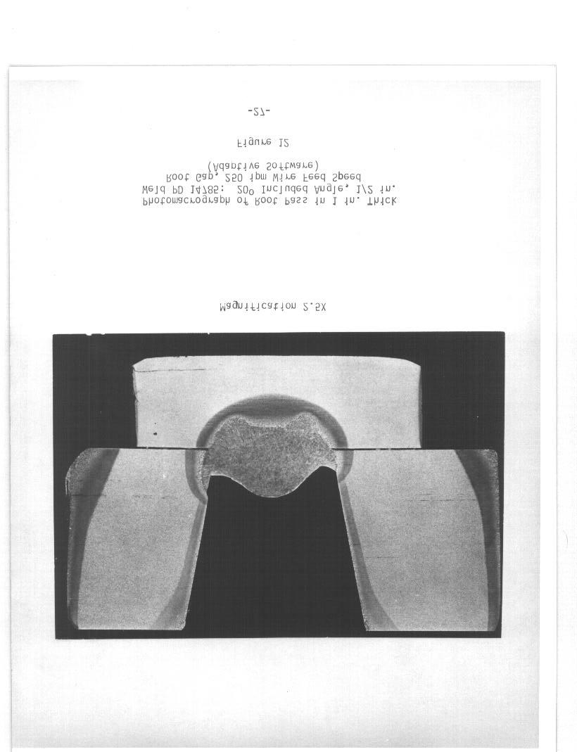
53 underfill and/or base meal undercut is less likely to occur with this upgraded routine because the arc is brought up onto the surface of the base plate, about 1/8 in. from the top corner of the bevel. It should also be noted that the operator has the ability to adjust bead width and centerline position within certain limits during the course of welding through use of buttons mounted on the travel carriage. In summary, with the upgraded routine, only one setup procedure is required, regardless of the type of bead required. The computer automatically determines the type of bead required and the optimum parameters. With less than in. of groove depth remaining, optimum parameters are set by the computer, but no tracking is performed. In this case, the operator has control of the bead width and centerline position (within certain limits). On finish passes, parameters are set by the computer to produce a nominal 1/8 in. reinforcament height. Bead Shape and Size One of the conclusions from the initial evaluation was that beads were frequently deposited at heat inputs far less than routinely used with mechanized equipment. In addition, bead shapes were not always satisfactory. Therefore, revised algorithms describing the welding technique were developed to improve bead shape and size. To facilitate the development of the improved algorithms, Electric Boat Division welded vertical position test plates at 250 ipm wire feed speed using the M-1OOO and a special program that allowed manual input and control of all welding parameters. 45 included angle single-v joints were welded at what was considered to be optimum parameters (maximum possible heat input, best possible bead shape) for root gaps of 1/16, 1/8, 1/4, 3/8, 1/2 and 1 in. For each bead of -45-
54 each plate, measurements of bead thickness and width were made. Table II shows the bead pattern and heat input used for each plate. (It should be noted that at times the 100 kj /in heat input limit was exceeded because of the inaccuracy of the M-1OOO travel speed). Figures 16, 17 and 18 are macrosections removed from three of the plates. All six plates met magnetic particle (backing bar removed) and radiographic inspection requirements. This data, along with other parametric data from previous EBDiv. work, were supplied to CRC and aided in the development of improved welding technique algorithms. The six plates discussed above proved that the M-1OOO was capable of depositing sound weld metal with good bead shapes at maximum heat inputs if the welding parameters are selected and controlled by the operator. Translation of the optimum welding parameters into algorithms is not an easy task because aspects of the welding technique must also be considered. Four areas of technique of particular importance are: single bead root passes; single and split bead fill passes; and finish passes. A good single bead root pass over a backing bar is deposited at the maximum feasible heat input, provides full root fusion, and is not overly convex or concave in shape. The technique used varies with the root gap. For a constant wire feed speed, as the root gap decreaaes below a certain value, the travel speed must generally increase to prevent the arc from riding excessively high on the puddle. In addition, it is beneficial to decrease the contact tip to work distance to increase the penetration. As showm by the data in Table II, it is possible to deposit successful root passes at over 80 kj /in heat input if the root gap is at least 1/8 in. Below 1/8 in. root gap, the travel speed must be increased to insure full penetration. For all of the root gaps represented 46-
55 1/16 in, Root Gap 1/8 in. Root Gap 1/4 in. Root Gap Bead Heat Input (k.j/in) /8 in. Root Gap Bead Patterns and Heat Inputs: Parameters and Heat Input - Manual Optimum Input Program Table II
56 1/2 in. Root Gap Table II (continued)
57
58
59
60 in Table II, the oscillation parameters were adjusted to provide for a relatively flat bead contour while still allowing full penetration. Thus, there is a delicate balance between penetration, bead shape, and bead size. In order to maximize the heat input and maintain a good bead shape, the arc must impinge on the sidewall to provide a sufficient heat sink. However, if too much of the arc energy is absorbed by the sidewalls, penetration will be reduced. In addition, if the arc characteristics are not proper (such as arc too soft, too broad, too long), penetration will be reduced. Dif f erencea of 1/16 in. in root gap may greatly change the parameters and technique required. Therefore, algorithms which accurately reflect root pass parameters and techniques are essential for successful root pass welding using the M-1OOO. The sensitivity of single and split fill pass bead shape and quality to the exact parameters and technique used is slightly more forgiving than for root passes, but a fine balance still exists between parameters that produce good beads and those which produce unacceptable beads. Heat inputs in excess of 90 kj /in are almost always usable for the first fill pass over the root, and in fact, for all additional single bead layer fill passes. However, in order to maintain a flat bead contour, the arc must be properly positioned with respect to the sidewall and proper oscillation parameters are required. As the groove width increases, the bead thickness for a given travel speed decreases. AC this occurs, the proper positioning of the arc and oscillation parameter requirements change. 52
61 TO deposit successful split bead fill passes with maximum bead size, location of each bead with respect to the sidewall and bead shape are critical. In the Electric Boat technique, all split passes are deposited in such a way and with such 90 kj /in for each bead. a ahape to allow use of heat inputs in excess of Again, oscillation parameters and arc location are critical. Deposition of successful finish passes is also challenging because the bead shape is very sensitive to the oscillation parameters and the underbead contour at the high heat inputa used. Deposition of unacceptable finish passes featuring high crowns or excessive reinforcement, undercut, or underfill will result in extensive rework. In sunmery, successful high heat input PGMAW is highly dependent on oscillation parameters, arc characteristics, and technique. Development of algorithms which accurately describe the welding procedure are essential for successful application of the M-1OOO. Algorithms which produce good quality beads at heat inputs below that possible with mechanized equipment or algorithms which produce beads of size equal to those possible with mechanized equipment, but with poor bead shape or defects, are unacceptable. Change to Constant End Face Volume Routine As previously discussed, the H-1OOO was programmed to maintain a constant bead thickness, within the limits of the allowed heat input range, even though the groove geometry might change during the course of welding. Although this may appear desirable, it may actually result in a problem if welding is performed over tacks or excavations. Considering the case of tacks, the H-1OOO is programmed with the ability to deposit a continuous root 53-
62 pass regardless of any small tacks in the groove. With the constant bead thickness routine, the shape of the tacks will be carried up through each layer, possibly resulting in a finish layer of varying thickness. In an attempt to correct this problem, a constant end face volume routine was implemented in place of the constant bead thickness routine. In this routine, a constant bead thickness is maintained unless the computer detects a rapid change in groove depth. when this occurs, the change in depth is subtracted from or added to the current bead thickness. The computer makes adaptive changes in AC, dwell, travel speed, etc., to compensate for the new bead thickness. These changes are accomplished to the extent possible withir i the allowable heat input range. Successful implementation of this routine should help to sutornatically produce level beads even though the depth of the groove varied at some point during welding. Restarting Problems One of the problems found with restarting a weld was the inability to model the actual portion of the groove to be welded; modeling on the crater of the partially deposited bead was required. This resulted in an incorrect model of the groove at the start location. The software was modified to allow the groove to be modeled at any location along the length of the weld. After the modeling is complete, the operator can move the start position to the point desired. By modeling the groove a short distance ahead of the crater of the partial bead and restarting the arc on the crater, oscillation and welding parameters closer to those desired may be obtained sooner than if modeling had been performed on the crater itself. 54
63 Improve Tracking Adjustment The limit on the number of consecutive corrections of oscillation position was eliminated to allow more flegibility in tracking adjustment Evaluation of Uograded M-1OOO (December 1983 April 1984) Sixteen 1 in. thick test plates were welded between December 1983 and April 1984 using the upgraded M-1OOO. During this period, four different revisions of adaptive software were used. The root gaps used ranged from 1/8 to 3/4 in.; the included angle was held constant at ipm wire feed speed was used exclusively. Results of the weld tests were encouraging in that passes, both single and split bead, could be deposited good quality fill and the startup routine was much simpler to use. The automatic modeling routines performed well and generally made the correct decisions as to the type of bead required. The width and oscillation centerline adjustments now possible with the last fill and finish pass routines also appeared to function satisfactorily. Finally, higher heat inputs were used than before the M-1OOO update, resulting in larger size weld beads. However, although the results showed that significant progress had been made, serious problems still remained with bead shape, root pass penetration, contact tip life, arc starting and restarting, tracking response, and inadequate cleaning for proper operation of the modeling routines. Each of these problems will be discussed below. -55-
64 1) Bead Shape/Guality Problems When used with the last revision software tested, travel speeds were generally in the range desired to maximize the bead size and minimize the number of beads required. However, there were deficiencies in bead ahape and quality, especially with root and finish passes. With root 1/2 in., incomplete root penetration consistently resulted, gaps less than although bead contours were generally flat. This problem appears to be related to the manner in which the M-1OOO adjusts its contact tip to work distance. The M-1OOO adjusts its tip to work distance based on current and voltage samples obtained at the centerline position of the oscillation stroke. When the arc mainly impinges on the leading edge of the weld puddle as the torch position crosses centerline, the current and voltage samples reflect the physical contact tip to work distance. However, if the bead thickness is increased, the arc tends to ride up somewhat more on the surface of the puddle. With standard mechanized welding, the physical tip to work distance may be mechanically held at the same distance as if the bead thickness were less. Howaver, with the M-1OOO, the tip to work distance is actually the distance from the tip to the point where the arc impinges on the molten metal. Thus, if the arc is riding up on the surface of the puddle, the tip to backing bar (or underbead surface) distance will be greater than desired. This greatly reduces the penetration into the backing bar or underbead surface. (It should be noted that this is usually not a problem with vertical mechanized welding because the tip to work distance is maintained with respect to the underbead surface). In addition, because the arc is riding too high up on -56
65 the puddle, the oscillation width (driven by the requirement to perform sidewall tracking) will be greater than OPtimum. This further reduces the penetration into the root because the arc must penetrate through a greater thickness of base metal to reach the backing bar. At this point, the M 1OOO was found to respond in one of two ways. The more common response was for the oscillation width to continue to increase (as a result of the high AC used and the riding up on the puddle), and the travel speed to slow dowm in response to the increasing width. When the maximum allowed heat input for that bead is reached, the oscillation width continues to increase. This results in a decrease in the puddle thickness, which then causes the torch to drive in towards the weld puddle to maintain the required tip to work distance. This causes the physical tip to work distance to decrease. In response to the decrease in physical tip to work distance, the arc now impinges higher up on the sidewalls than required to satisfy AC. This causes a decrease in the oscillation width and an increase. in travel speed. After a short period of time the cycle repeats itself. The other observed response to the arc riding too high up on the puddle is for the physical tip to work distance to slowly increase accompanied by an increase in the oscillation width and the corresponding decrease in travel spead. This occurs up to the point when the maximum heat input is reached. Unlike the former case, the parameters hold steady for the remainder of the joint, as long as the groove dimensions do not change. This phenomenon is illustrated in Figure 19. In this constant root gap (1/4 in. ) joint, the oscillation width is shown to increase along the length of the weld. Macrosections from a similar weld are shown in Figures 20 and 21. Figure 20 was removed from a point near the weld start, while Figure 21 represents a 57-
66
67
68
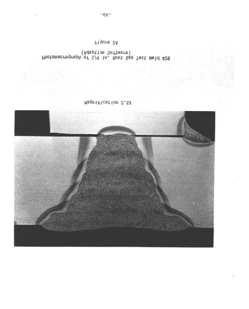
69 point near the weld stop. It is clearly shown in Figure 20 that only minimal penetration into the backing bar occurred. In Figure 21, no backing bar penetration took place and, in fact, there was lack of fusion against the bevel at the root. Although a root pass as shown in Figure 20 is technically acceptable, it is so close to being unacceptable that the quality of actual production root passes could not be guaranteed. The problems described above can be reduced or eliminated by reducing the heat input. However, this will increase welding times by increasing the number of beads required. Figures 22, 23 and 24 show photomacrographs 3/8, 1/8 and 1/4 in., respectively. These welds of welds with root gaps of were produced with the last revision of adaptive softwaree tested. Generally root pass penetration was marginal to unacceptable but root pass shape was good. On all three test plates, the travel speed either started out fast then slowed down or started out slow then increased. This resulted in uneven fill over the length of the joint. Because of this, the fill passes (which used automatic tracking and adaptive control), all followed the trend of the root pass. That is, the uneven root pass thickness was carried up through all the fill passes meaning that when the joint was nearly flush on one end, it was up to 1/4 in. underf lush on the other end. Since finish passes are deposited without the ability to change the travel speed, uneven reinforcement height resulted. As shown in Figures 22 24, quality fill passes were deposited. Bead sizes were reasonably close to those deposited using the manual input program (Table 11). Bead shapes were generally satisfactory. However, finish pass -61-
70
71
72

73 shapes were less than ideal. Single bead finish passes tended to have too much metal at the toes and were concave near the center. Split bead finish passes tended to be overly convex and generally produced excessive reinforcement. This was caused by the choice of leas than optimum oscillation parameters by the algorithms. In summary, problems with root pass penetration and maintenance of constant root pass parameters existed. quality with good bead shapes. Finish Fill passes were generally of good bead shapes were generally undesirable. Bead by bead heat inputs were close to those considered Optimum. Overall, significant improvements were made in bead size and shape over software available prior to the M 1OOO upgrade. 2) Arc Starting and Restarting Occasionally porosity appeared at the start. This was caused by an excessive gas cup to work distance during the four oscillation cycle period at the start where current and voltage samples are taken and during the following oscillation cycles where the computer is making adjustment in width, tip to work distance, etc. It should be noted that the contact tip must be extended at least 3/32 in. past the end of the gas cup to allow it to make electrical contact with the base plate surf ace during modeling. This requirement results in greater cup to work distances than in mechanized welding and contributes to poorer shielding. The new restart routine which allows modeling at any location and restarting at any location was tested. Although the routine worked well, the problem previously described with the delay in assuming proper tip to work distance was still present. As a result, by the time the proper contact tip to work distance was established, the arc was well past the restart point.
74 3) Uneven Fill Height In mechanized welding, it is desirable to have a relatively constant depth of groove remaining along the weld length before depositing finish paases. It was hoped that the M-1OOO with the constant end face volume routine previously discussed would provide this automatically. On tast plates where the root pass thickness varied along the length, this condition was carried up through the finish layer. The reason for this was that in order for the computer to detect that a change in bead thickness is required, the underbead profile must change by at least in. over two consecutive oscillation sweeps. period of 3.9 sec., (37 ) is requirad. For a typical travel speed of 2 ipm and oscillation a height change of in. over in. of travel This is a relatively steep incline which may only occur with 4) some tacks or starts/stops. Tracking. Response Using the last revision program, tracking appeared to work well in single bead root and fill passes. 5) Cleaning Requirements Tracking response was not teated. Extremely good cleaning was required in the area to be modeled to prevent mis modeling and/or bad starts. This was especially true when extensiva modeling of the groove was required, such as for split bead fill passes or finish passes. Generally light burring or grinding was required to inaura a successful modeling routine. -66-
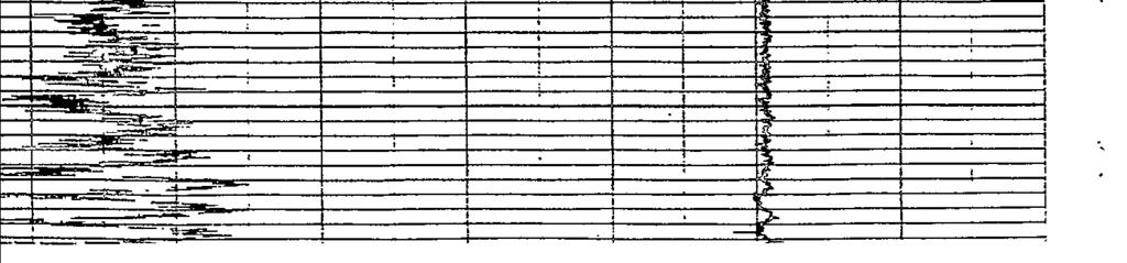
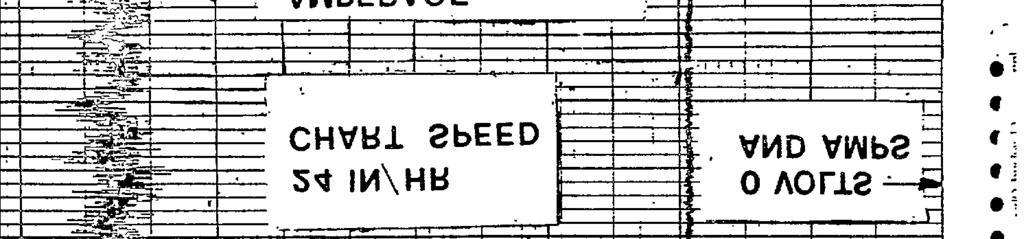
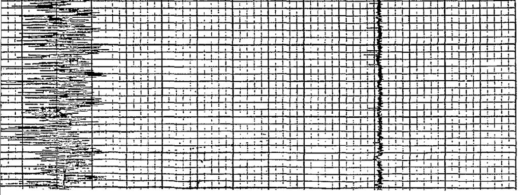
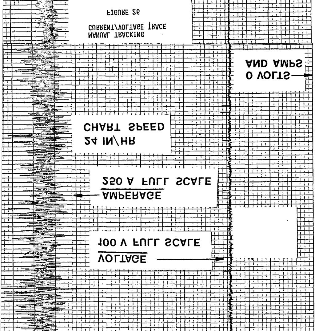
75 NOTE: The following observations were made using the upgraded M-1OOO hardware with the manual input software. Vertical position test plates 50 to 75 in. long were welded at heat inputs UP to 110 kj /in. Automatic and manual tracking beads were both possible with this progrsm. 6) Contact Tip Life As discussed in Section 8.2, the contact tip life was 20 to 60 arc minutes. This was based on arc appearance and quality. However, while welding the 75 in. test plates, several new factors appeared. Using automatic tracking, the arc quality would start to degrade slightly after 15 to 20 arc minutes. This was indicated by an increase in amperage and voltage ranges on chart racorder traces (Figure 25). Coincident with this was the beginning of tracking problems. This was characterized by excessive corrections of the arc position with respect to the sidewalls which increased in frequency as the arc time on the tip increased. Several times the bead shape was affected to the point where it became unacceptable (usually overly convex), and welding had to be stopped to change the contact tip. In beads deposited using manual tracking, arc quality also began to degrade after 15 to 20 arc minutes (see Figure 26). However, welding could be successfully continued for the duration of the bead because manual tracking was used. Thus, when automatic tracking is used, contact tip life is measured by how long tracking can be successfully performed. With manual tracking, contact tip life is measured by how long acceptable arc characteristics can be maintained. It is estimated that tip life with automatic tracking is about 50% of that with manual tracking. 7) Travel Drive and Oscillator Problems Mechnical problems were encountered with the travel drive and oscillator assemblies. On three occasions, bearings in the travel drive assembly -67-
76
77
SHIPBUILDING ACCURACY PHASE II
 FINAL REPORT NORTH AMERICAN SHIPBUILDING ACCURACY PHASE II Submitted to the: Maritime Administration through Newport News Shipbuilding Newport News, VA July 9, 1993 Project Director: Howard M. Bunch Principal
Standards and Competencies
 Skill Performance The skill performance assessment includes the completion of a metal project and a demonstration of the ability to weld carbon steel, aluminum or stainless-steel project in various using
SMAW LESSON #1: Initiating and maintaining an arc using the scratch start method
 SMAW LESSON #1: Initiating and maintaining an arc using the scratch start method OBJECTIVE: Upon completion of this lesson the learner will be able to strike and maintain an arc using SMAW on steel plate
Module 4 Design for Assembly IIT BOMBAY
 Module 4 Design for Assembly Lecture 8 Case Studies - IV Instructional objectives The objective of this lecture is to exhibit how real components are designed in industry following some of the principles
VISUAL REFERENCE STANDARDS FOR WELD SURFACE CONDITIONS (PHASE II) U.S. DEPARTMENT OF TRANSPORTATION
 U.S. DEPARTMENT OF TRANSPORTATION") THE NATIONAL SHIPBUILDING RESEARCH PROGRAM VISUAL REFERENCE STANDARDS FOR WELD SURFACE CONDITIONS (PHASE II) U.S. DEPARTMENT OF TRANSPORTATION Report Documentation Page Form Approved OMB No. 0704-0188
THE NATIONAL SHIPBUILDING RESEARCH PROGRAM VISUAL REFERENCE STANDARDS FOR WELD SURFACE CONDITIONS (PHASE II) U.S. DEPARTMENT OF TRANSPORTATION Report Documentation Page Form Approved OMB No. 0704-0188
WELDING FABRICATION NYS
 WELDING FABRICATION NYS PURPOSE To evaluate each contestant s preparation for employment and to recognize outstanding students for excellence and professionalism in the field of fabrication. ELIGIBILITY
THE NATIONAL SHIPBUILDING RESEARCH PROGRAM
 SHIP PRODUCTION COMMITTEE FACILITIES AND ENVIRONMENTAL EFFECTS SURFACE PREPARATION AND COATINGS DESIGN/PRODUCTION INTEGRATION HUMAN RESOURCE INNOVATION MARINE INDUSTRY STANDARDS WELDING INDUSTRIAL ENGINEERING
High Speed Machining of IN100. Final Report. Florida Turbine Technology (FTT) Jupiter, FL
 Jupiter, FL") High Speed Machining of IN100 Reference NCDMM SOW: 21NCDMM05 Final Report Florida Turbine Technology (FTT) Jupiter, FL Submitted by Doug Perillo National Center for Defense Manufacturing & Machining Doug
High Speed Machining of IN100 Reference NCDMM SOW: 21NCDMM05 Final Report Florida Turbine Technology (FTT) Jupiter, FL Submitted by Doug Perillo National Center for Defense Manufacturing & Machining Doug
REPORT DOCUMENTATION PAGE
 REPORT DOCUMENTATION PAGE Form Approved OMB No. 0704-0188 Public reporting burden for this collection of information is estimated to average 1 hour per response, including the time for reviewing instructions,
DEVELOPMENT OF AN ULTRA-COMPACT EXPLOSIVELY DRIVEN MAGNETIC FLUX COMPRESSION GENERATOR SYSTEM
 DEVELOPMENT OF AN ULTRA-COMPACT EXPLOSIVELY DRIVEN MAGNETIC FLUX COMPRESSION GENERATOR SYSTEM J. Krile ξ, S. Holt, and D. Hemmert HEM Technologies, 602A Broadway Lubbock, TX 79401 USA J. Walter, J. Dickens
Making Butt Welds with Power Wave AC/DC 1000 Technology UNLIMITED AC OUTPUT TAILORING REDUCTION IN DEFECTS LOWER COSTS
 WAVEFORM CONTROL TECHNOLOGY TM Now from Lincoln - the power to increase butt welding productivity and quality with Power Wave Technology! Butt-welded joints can involve a multitude of differing geometries
THE NATIONAL SHIPBUILDING RESEARCH PROGRAM
 SHIP PRODUCTION COMMITTEE FACILITIES AND ENVIRONMENTAL EFFECTS SURFACE PREPARATION AND COATINGS DESIGN/PRODUCTION INTEGRATION HUMAN RESOURCE INNOVATION MARINE INDUSTRY STANDARDS WELDING INDUSTRIAL ENGINEERING
Digital Radiography and X-ray Computed Tomography Slice Inspection of an Aluminum Truss Section
 Digital Radiography and X-ray Computed Tomography Slice Inspection of an Aluminum Truss Section by William H. Green ARL-MR-791 September 2011 Approved for public release; distribution unlimited. NOTICES
Buttress Thread Machining Technical Report Summary Final Report Raytheon Missile Systems Company NCDMM Project # NP MAY 12, 2006
 Improved Buttress Thread Machining for the Excalibur and Extended Range Guided Munitions Raytheon Tucson, AZ Effective Date of Contract: September 2005 Expiration Date of Contract: April 2006 Buttress
Welding Qualification/Certification
 Welding Qualification/Certification 9/14/2011 1 Index Page Number Pre-testing Procedure 3 Bend Test Procedure Coupons 4 Drawing for cutting Coupons and Back strap removal 5-9 Preparation and Testing Procedure
THE NATIONAL SHIPBUILDING RESEARCH PROGRAM
 SHIP PRODUCTION COMMITTEE FACILITIES AND ENVIRONMENTAL EFFECTS SURFACE PREPARATION AND COATINGS DESIGN/PRODUCTION INTEGRATION HUMAN RESOURCE INNOVATION MARINE INDUSTRY STANDARDS WELDING INDUSTRIAL ENGINEERING
Loop-Dipole Antenna Modeling using the FEKO code
 Loop-Dipole Antenna Modeling using the FEKO code Wendy L. Lippincott* Thomas Pickard Randy Nichols lippincott@nrl.navy.mil, Naval Research Lab., Code 8122, Wash., DC 237 ABSTRACT A study was done to optimize
Investigation of a Forward Looking Conformal Broadband Antenna for Airborne Wide Area Surveillance
 Investigation of a Forward Looking Conformal Broadband Antenna for Airborne Wide Area Surveillance Hany E. Yacoub Department Of Electrical Engineering & Computer Science 121 Link Hall, Syracuse University,
HIGH TEMPERATURE (250 C) SIC POWER MODULE FOR MILITARY HYBRID ELECTRICAL VEHICLE APPLICATIONS
 SIC POWER MODULE FOR MILITARY HYBRID ELECTRICAL VEHICLE APPLICATIONS") HIGH TEMPERATURE (250 C) SIC POWER MODULE FOR MILITARY HYBRID ELECTRICAL VEHICLE APPLICATIONS R. M. Schupbach, B. McPherson, T. McNutt, A. B. Lostetter John P. Kajs, and Scott G Castagno 29 July 2011 :
HIGH TEMPERATURE (250 C) SIC POWER MODULE FOR MILITARY HYBRID ELECTRICAL VEHICLE APPLICATIONS R. M. Schupbach, B. McPherson, T. McNutt, A. B. Lostetter John P. Kajs, and Scott G Castagno 29 July 2011 :
Radar Detection of Marine Mammals
 DISTRIBUTION STATEMENT A. Approved for public release; distribution is unlimited. Radar Detection of Marine Mammals Charles P. Forsyth Areté Associates 1550 Crystal Drive, Suite 703 Arlington, VA 22202
COM DEV AIS Initiative. TEXAS II Meeting September 03, 2008 Ian D Souza
 COM DEV AIS Initiative TEXAS II Meeting September 03, 2008 Ian D Souza 1 Report Documentation Page Form Approved OMB No. 0704-0188 Public reporting burden for the collection of information is estimated
REPORT DOCUMENTATION PAGE
 REPORT DOCUMENTATION PAGE Form Approved OMB No. 0704-0188 The public reporting burden for this collection of information is estimated to average 1 hour per response, including the time for reviewing instructions,
Underwater Intelligent Sensor Protection System
 Underwater Intelligent Sensor Protection System Peter J. Stein, Armen Bahlavouni Scientific Solutions, Inc. 18 Clinton Drive Hollis, NH 03049-6576 Phone: (603) 880-3784, Fax: (603) 598-1803, email: pstein@mv.mv.com
Development of a charged-particle accumulator using an RF confinement method FA
 Development of a charged-particle accumulator using an RF confinement method FA4869-08-1-4075 Ryugo S. Hayano, University of Tokyo 1 Impact of the LHC accident This project, development of a charged-particle
Coherent distributed radar for highresolution
 . Calhoun Drive, Suite Rockville, Maryland, 8 () 9 http://www.i-a-i.com Intelligent Automation Incorporated Coherent distributed radar for highresolution through-wall imaging Progress Report Contract No.
WELDING FABRICATION. First, download and review the General Regulations at: updates.skillsusa.org.
 WELDING FABRICATION PURPOSE To evaluate each contestant s preparation for employment and to recognize outstanding students for excellence and professionalism in the field of fabrication. First, download
Evanescent Acoustic Wave Scattering by Targets and Diffraction by Ripples
 Evanescent Acoustic Wave Scattering by Targets and Diffraction by Ripples PI name: Philip L. Marston Physics Department, Washington State University, Pullman, WA 99164-2814 Phone: (509) 335-5343 Fax: (509)
INVESTIGATION OF A HIGH VOLTAGE, HIGH FREQUENCY POWER CONDITIONING SYSTEM FOR USE WITH FLUX COMPRESSION GENERATORS
 INVESTIGATION OF A HIGH VOLTAGE, HIGH FREQUENCY POWER CONDITIONING SYSTEM FOR USE WITH FLUX COMPRESSION GENERATORS K. A. O Connor ξ and R. D. Curry University of Missouri-Columbia, 349 Engineering Bldg.
REPORT DOCUMENTATION PAGE. A peer-to-peer non-line-of-sight localization system scheme in GPS-denied scenarios. Dr.
 REPORT DOCUMENTATION PAGE Form Approved OMB No. 0704-0188 The public reporting burden for this collection of information is estimated to average 1 hour per response, including the time for reviewing instructions,
REPORT DOCUMENTATION PAGE
 REPORT DOCUMENTATION PAGE Form Approved OMB No. 0704-0188 Public reporting burden for this collection of information is estimated to average 1 hour per response, including the time for reviewing instructions,
Hybrid QR Factorization Algorithm for High Performance Computing Architectures. Peter Vouras Naval Research Laboratory Radar Division
 Hybrid QR Factorization Algorithm for High Performance Computing Architectures Peter Vouras Naval Research Laboratory Radar Division 8/1/21 Professor G.G.L. Meyer Johns Hopkins University Parallel Computing
Low Hydrogen Embrittlement (LHE) Zinc-Nickel (Zn-Ni) Qualification Test Result and Process Parameters Development
 Zinc-Nickel (Zn-Ni) Qualification Test Result and Process Parameters Development") Low Hydrogen Embrittlement (LHE) Zinc-Nickel (Zn-Ni) Qualification Test Result and Process Parameters Development Dave Frederick, USAF Chad Hogan, USAF August 2011 1 Report Documentation Page Form Approved
Low Hydrogen Embrittlement (LHE) Zinc-Nickel (Zn-Ni) Qualification Test Result and Process Parameters Development Dave Frederick, USAF Chad Hogan, USAF August 2011 1 Report Documentation Page Form Approved
Active Denial Array. Directed Energy. Technology, Modeling, and Assessment
 Directed Energy Technology, Modeling, and Assessment Active Denial Array By Randy Woods and Matthew Ketner 70 Active Denial Technology (ADT) which encompasses the use of millimeter waves as a directed-energy,
Durable Aircraft. February 7, 2011
 Durable Aircraft February 7, 2011 Report Documentation Page Form Approved OMB No. 0704-0188 Public reporting burden for the collection of information is estimated to average 1 hour per response, including
Reduced Power Laser Designation Systems
 REPORT DOCUMENTATION PAGE Form Approved OMB No. 0704-0188 The public reporting burden for this collection of information is estimated to average 1 hour per response, including the time for reviewing instructions,
August 9, Attached please find the progress report for ONR Contract N C-0230 for the period of January 20, 2015 to April 19, 2015.
 August 9, 2015 Dr. Robert Headrick ONR Code: 332 O ce of Naval Research 875 North Randolph Street Arlington, VA 22203-1995 Dear Dr. Headrick, Attached please find the progress report for ONR Contract N00014-14-C-0230
IB2-1 HIGH AVERAGE POWER TESTS OF A CROSSED-FIELD CLOSING SWITCH>:< Robin J. Harvey and Robert W. Holly
 HIGH AVERAGE POWER TESTS OF A CROSSED-FIELD CLOSING SWITCH>:< by Robin J. Harvey and Robert W. Holly Hughes Research Laboratories 3011 Malibu Canyon Road Malibu, California 90265 and John E. Creedon U.S.
Innovative 3D Visualization of Electro-optic Data for MCM
 Innovative 3D Visualization of Electro-optic Data for MCM James C. Luby, Ph.D., Applied Physics Laboratory University of Washington 1013 NE 40 th Street Seattle, Washington 98105-6698 Telephone: 206-543-6854
ANALYSIS OF A PULSED CORONA CIRCUIT
 ANALYSIS OF A PULSED CORONA CIRCUIT R. Korzekwa (MS-H851) and L. Rosocha (MS-E526) Los Alamos National Laboratory P.O. Box 1663, Los Alamos, NM 87545 M. Grothaus Southwest Research Institute 6220 Culebra
Best Practices for Technology Transition. Technology Maturity Conference September 12, 2007
 Best Practices for Technology Transition Technology Maturity Conference September 12, 2007 1 Report Documentation Page Form Approved OMB No. 0704-0188 Public reporting burden for the collection of information
Welding 2 go. alhuzaim_af [Type the company name] 8/2/2012
![Welding 2 go. alhuzaim_af [Type the company name] 8/2/2012](/thumbs/86/93471492.jpg "Welding 2 go. alhuzaim_af [Type the company name] 8/2/2012") 2012 Welding 2 go alhuzaim_af [Type the company name] 8/2/2012 One must try by doing the thing; for though you think you know it, you have no certainty until you try. - Sophocles 2 I would like to express
2012 Welding 2 go alhuzaim_af [Type the company name] 8/2/2012 One must try by doing the thing; for though you think you know it, you have no certainty until you try. - Sophocles 2 I would like to express
Thermal Simulation of a Silicon Carbide (SiC) Insulated-Gate Bipolar Transistor (IGBT) in Continuous Switching Mode
 Insulated-Gate Bipolar Transistor (IGBT) in Continuous Switching Mode") ARL-MR-0973 APR 2018 US Army Research Laboratory Thermal Simulation of a Silicon Carbide (SiC) Insulated-Gate Bipolar Transistor (IGBT) in Continuous Switching Mode by Gregory Ovrebo NOTICES Disclaimers
ARL-MR-0973 APR 2018 US Army Research Laboratory Thermal Simulation of a Silicon Carbide (SiC) Insulated-Gate Bipolar Transistor (IGBT) in Continuous Switching Mode by Gregory Ovrebo NOTICES Disclaimers
ANALYSIS OF SWITCH PERFORMANCE ON THE MERCURY PULSED- POWER GENERATOR *
 ANALYSIS OF SWITCH PERFORMANCE ON THE MERCURY PULSED- POWER GENERATOR * T. A. Holt, R. J. Allen, R. C. Fisher, R. J. Commisso Naval Research Laboratory, Plasma Physics Division Washington, DC 20375 USA
Argus Development and Support
 Argus Development and Support Rob Holman SECNAV/CNO Chair in Oceanography COAS-OSU 104 Ocean Admin Bldg Corvallis, OR 97331-5503 phone: (541) 737-2914 fax: (541) 737-2064 email: holman@coas.oregonstate.edu
A COMPACT, 1-MV, 6-kA RADIOGRAPHY SOURCE WITH A ONE- METER EXTENSION AND RIGHT-ANGLE BEND
 A COMPACT, 1-MV, 6-kA RADIOGRAPHY SOURCE WITH A ONE- METER EXTENSION AND RIGHT-ANGLE BEND B. M. Huhman ξ a, R. J. Allen, G. Cooperstein, D. Mosher b, J.W. Schumer, F.C. Young b Plasma Physics Division,
Combining High Dynamic Range Photography and High Range Resolution RADAR for Pre-discharge Threat Cues
 Combining High Dynamic Range Photography and High Range Resolution RADAR for Pre-discharge Threat Cues Nikola Subotic Nikola.Subotic@mtu.edu DISTRIBUTION STATEMENT A. Approved for public release; distribution
AUTOMATIC CIRCLE BURNING AND WELDING ON PIPE AND PRESSURE VESSELS
 AUTOMATIC CIRCLE BURNING AND WELDING ON PIPE AND PRESSURE VESSELS No Hose or Cable Wrapup Regardless of Direction of Rotation. Oxy-Fuel Cutting Units. Plasma Cutting Units. Welding Units. CYPRESS WELDING
THE DET CURVE IN ASSESSMENT OF DETECTION TASK PERFORMANCE
 THE DET CURVE IN ASSESSMENT OF DETECTION TASK PERFORMANCE A. Martin*, G. Doddington#, T. Kamm+, M. Ordowski+, M. Przybocki* *National Institute of Standards and Technology, Bldg. 225-Rm. A216, Gaithersburg,
REPORT DOCUMENTATION PAGE
 REPORT DOCUMENTATION PAGE Form Approved OMB No. 0704-0188 Public reporting burden for this collection of information is estimated to average 1 hour per response, including the time for reviewing instructions,
Bistatic Underwater Optical Imaging Using AUVs
 Bistatic Underwater Optical Imaging Using AUVs Michael P. Strand Naval Surface Warfare Center Panama City Code HS-12, 110 Vernon Avenue Panama City, FL 32407 phone: (850) 235-5457 fax: (850) 234-4867 email:
Technology Maturation Planning for the Autonomous Approach and Landing Capability (AALC) Program
 Program") Technology Maturation Planning for the Autonomous Approach and Landing Capability (AALC) Program AFRL 2008 Technology Maturity Conference Multi-Dimensional Assessment of Technology Maturity 9-12 September
Technology Maturation Planning for the Autonomous Approach and Landing Capability (AALC) Program AFRL 2008 Technology Maturity Conference Multi-Dimensional Assessment of Technology Maturity 9-12 September
ULTRASTABLE OSCILLATORS FOR SPACE APPLICATIONS
 ULTRASTABLE OSCILLATORS FOR SPACE APPLICATIONS Peter Cash, Don Emmons, and Johan Welgemoed Symmetricom, Inc. Abstract The requirements for high-stability ovenized quartz oscillators have been increasing
MONITORING RUBBLE-MOUND COASTAL STRUCTURES WITH PHOTOGRAMMETRY
 ,. CETN-III-21 2/84 MONITORING RUBBLE-MOUND COASTAL STRUCTURES WITH PHOTOGRAMMETRY INTRODUCTION: Monitoring coastal projects usually involves repeated surveys of coastal structures and/or beach profiles.
8.2. Washington, D. C delivered 65 kj into a matched load with 63 ns FWHM. Peak power was about 1 TW.
 205 8.2 STATUS OF THE UPGRADED VERSION OF THE NRL G~~LE II PULSE POWER GENERATOR J. R. Boller, J. K. Burton and J. D. Shipman, Jr. Naval Research Laboratory Washington, D. C. 20375 Abst::-act The GA}ffiLE
AUVFEST 05 Quick Look Report of NPS Activities
 AUVFEST 5 Quick Look Report of NPS Activities Center for AUV Research Naval Postgraduate School Monterey, CA 93943 INTRODUCTION Healey, A. J., Horner, D. P., Kragelund, S., Wring, B., During the period
Ocean Acoustics and Signal Processing for Robust Detection and Estimation
 Ocean Acoustics and Signal Processing for Robust Detection and Estimation Zoi-Heleni Michalopoulou Department of Mathematical Sciences New Jersey Institute of Technology Newark, NJ 07102 phone: (973) 596
A RENEWED SPIRIT OF DISCOVERY
 A RENEWED SPIRIT OF DISCOVERY The President s Vision for U.S. Space Exploration PRESIDENT GEORGE W. BUSH JANUARY 2004 Report Documentation Page Form Approved OMB No. 0704-0188 Public reporting burden for
IREAP. MURI 2001 Review. John Rodgers, T. M. Firestone,V. L. Granatstein, M. Walter
 MURI 2001 Review Experimental Study of EMP Upset Mechanisms in Analog and Digital Circuits John Rodgers, T. M. Firestone,V. L. Granatstein, M. Walter Institute for Research in Electronics and Applied Physics
A Multi-Use Low-Cost, Integrated, Conductivity/Temperature Sensor
 A Multi-Use Low-Cost, Integrated, Conductivity/Temperature Sensor Guy J. Farruggia Areté Associates 1725 Jefferson Davis Hwy Suite 703 Arlington, VA 22202 phone: (703) 413-0290 fax: (703) 413-0295 email:
POSTPRINT UNITED STATES AIR FORCE RESEARCH ON AIRFIELD PAVEMENT REPAIRS USING PRECAST PORTLAND CEMENT CONCRETE (PCC) SLABS (BRIEFING SLIDES)
 SLABS (BRIEFING SLIDES)") POSTPRINT AFRL-RX-TY-TP-2008-4582 UNITED STATES AIR FORCE RESEARCH ON AIRFIELD PAVEMENT REPAIRS USING PRECAST PORTLAND CEMENT CONCRETE (PCC) SLABS (BRIEFING SLIDES) Athar Saeed, PhD, PE Applied Research
POSTPRINT AFRL-RX-TY-TP-2008-4582 UNITED STATES AIR FORCE RESEARCH ON AIRFIELD PAVEMENT REPAIRS USING PRECAST PORTLAND CEMENT CONCRETE (PCC) SLABS (BRIEFING SLIDES) Athar Saeed, PhD, PE Applied Research
OPTICAL EMISSION CHARACTERISTICS OF HELIUM BREAKDOWN AT PARTIAL VACUUM FOR POINT TO PLANE GEOMETRY
 OPTICAL EMISSION CHARACTERISTICS OF HELIUM BREAKDOWN AT PARTIAL VACUUM FOR POINT TO PLANE GEOMETRY K. Koppisetty ξ, H. Kirkici 1, D. L. Schweickart 2 1 Auburn University, Auburn, Alabama 36849, USA, 2
PULSED BREAKDOWN CHARACTERISTICS OF HELIUM IN PARTIAL VACUUM IN KHZ RANGE
 PULSED BREAKDOWN CHARACTERISTICS OF HELIUM IN PARTIAL VACUUM IN KHZ RANGE K. Koppisetty ξ, H. Kirkici Auburn University, Auburn, Auburn, AL, USA D. L. Schweickart Air Force Research Laboratory, Wright
RAVEN, A 5 kj, 1.5 MV REPETITIVE PULSER* G. J. Rohwein Sandia National Laboratories Albuquerque, New Mexico 87185
 RAVEN, A 5 kj, 1.5 MV REPETITIVE PULSER* G. J. Rohwein Sandia National Laboratories Albuquerque, New Mexico 87185 Summary RAVEN, a 5 kj, 1.5 MV repetitive pulser, was built to test the performance of high
INFRARED REFLECTANCE INSPECTION
 Infrared Reflectance Imaging for Corrosion Inspection Through Organic Coatings (WP-0407) Mr. Jack Benfer Principal Investigator NAVAIR Jacksonville, FL Tel: (904) 542-4516, x153 Email: john.benfer@navy.mil
Manufacturing Process - I Dr. D. K. Dwivedi Department of Mechanical and Industrial Engineering Indian Institute of Technology, Roorkee
 Manufacturing Process - I Dr. D. K. Dwivedi Department of Mechanical and Industrial Engineering Indian Institute of Technology, Roorkee Module - 3 Lecture - 5 Arc Welding Power Source Part 2 Welcome students.
Thermal Simulation of Switching Pulses in an Insulated Gate Bipolar Transistor (IGBT) Power Module
 Power Module") Thermal Simulation of Switching Pulses in an Insulated Gate Bipolar Transistor (IGBT) Power Module by Gregory K Ovrebo ARL-TR-7210 February 2015 Approved for public release; distribution unlimited. NOTICES
Thermal Simulation of Switching Pulses in an Insulated Gate Bipolar Transistor (IGBT) Power Module by Gregory K Ovrebo ARL-TR-7210 February 2015 Approved for public release; distribution unlimited. NOTICES
Strategic Technical Baselines for UK Nuclear Clean-up Programmes. Presented by Brian Ensor Strategy and Engineering Manager NDA
 Strategic Technical Baselines for UK Nuclear Clean-up Programmes Presented by Brian Ensor Strategy and Engineering Manager NDA Report Documentation Page Form Approved OMB No. 0704-0188 Public reporting
Lattice Spacing Effect on Scan Loss for Bat-Wing Phased Array Antennas
 Lattice Spacing Effect on Scan Loss for Bat-Wing Phased Array Antennas I. Introduction Thinh Q. Ho*, Charles A. Hewett, Lilton N. Hunt SSCSD 2825, San Diego, CA 92152 Thomas G. Ready NAVSEA PMS500, Washington,
U.S. Army Training and Doctrine Command (TRADOC) Virtual World Project
 Virtual World Project") U.S. Army Research, Development and Engineering Command U.S. Army Training and Doctrine Command (TRADOC) Virtual World Project Advanced Distributed Learning Co-Laboratory ImplementationFest 2010 12 August
U.S. Army Research, Development and Engineering Command U.S. Army Training and Doctrine Command (TRADOC) Virtual World Project Advanced Distributed Learning Co-Laboratory ImplementationFest 2010 12 August
SPOT 5 / HRS: a key source for navigation database
 SPOT 5 / HRS: a key source for navigation database CONTENT DEM and satellites SPOT 5 and HRS : the May 3 rd 2002 revolution Reference3D : a tool for navigation and simulation Marc BERNARD Page 1 Report
Operational Domain Systems Engineering
 Operational Domain Systems Engineering J. Colombi, L. Anderson, P Doty, M. Griego, K. Timko, B Hermann Air Force Center for Systems Engineering Air Force Institute of Technology Wright-Patterson AFB OH
New generation of welding and inspection systems
 New generation of welding and inspection systems Throughout the pipeline industry, and particularly in offshore and spool base production, welding requirements are shifting toward higher quality, greater
FAA Research and Development Efforts in SHM
 FAA Research and Development Efforts in SHM P. SWINDELL and D. P. ROACH ABSTRACT SHM systems are being developed using networks of sensors for the continuous monitoring, inspection and damage detection
[Research Title]: Electro-spun fine fibers of shape memory polymer used as an engineering part. Contractor (PI): Hirohisa Tamagawa
![[Research Title]: Electro-spun fine fibers of shape memory polymer used as an engineering part. Contractor (PI): Hirohisa Tamagawa](/thumbs/72/67640784.jpg "[Research Title]: Electro-spun fine fibers of shape memory polymer used as an engineering part. Contractor (PI): Hirohisa Tamagawa") [Research Title]: Electro-spun fine fibers of shape memory polymer used as an engineering part Contractor (PI): Hirohisa Tamagawa WORK Information: Organization Name: Gifu University Organization Address:
[Research Title]: Electro-spun fine fibers of shape memory polymer used as an engineering part Contractor (PI): Hirohisa Tamagawa WORK Information: Organization Name: Gifu University Organization Address:
NPAL Acoustic Noise Field Coherence and Broadband Full Field Processing
 NPAL Acoustic Noise Field Coherence and Broadband Full Field Processing Arthur B. Baggeroer Massachusetts Institute of Technology Cambridge, MA 02139 Phone: 617 253 4336 Fax: 617 253 2350 Email: abb@boreas.mit.edu
FLASH X-RAY (FXR) ACCELERATOR OPTIMIZATION BEAM-INDUCED VOLTAGE SIMULATION AND TDR MEASUREMENTS *
 ACCELERATOR OPTIMIZATION BEAM-INDUCED VOLTAGE SIMULATION AND TDR MEASUREMENTS *") FLASH X-RAY (FXR) ACCELERATOR OPTIMIZATION BEAM-INDUCED VOLTAGE SIMULATION AND TDR MEASUREMENTS * Mike M. Ong and George E. Vogtlin Lawrence Livermore National Laboratory, PO Box 88, L-13 Livermore, CA,
FLASH X-RAY (FXR) ACCELERATOR OPTIMIZATION BEAM-INDUCED VOLTAGE SIMULATION AND TDR MEASUREMENTS * Mike M. Ong and George E. Vogtlin Lawrence Livermore National Laboratory, PO Box 88, L-13 Livermore, CA,
CHARACTERIZATION OF PASCHEN CURVE ANOMOLIES AT HIGH P*D VALUES
 CHARACTERIZATION OF PASCHEN CURVE ANOMOLIES AT HIGH P*D VALUES W.J. Carey, A.J. Wiebe, R.D. Nord ARC Technology, 1376 NW 12 th St. Whitewater, Kansas, USA L.L. Altgilbers (Senior Member) US Army Space
Key Issues in Modulating Retroreflector Technology
 Key Issues in Modulating Retroreflector Technology Dr. G. Charmaine Gilbreath, Code 7120 Naval Research Laboratory 4555 Overlook Ave., NW Washington, DC 20375 phone: (202) 767-0170 fax: (202) 404-8894
REPORT DOCUMENTATION PAGE
 REPORT DOCUMENTATION PAGE Form Approved OMB No. 0704-0188 Public reporting burden for this collection of information is estimated to average 1 hour per response, including the time for reviewing instructions,
AUTOMATIC CIRCLE BURNING AND WELDING
 AUTOMATIC CIRCLE BURNING AND WELDING ON PIPE AND PRESSURE VESSELS No Hose or Cable Wrapup (Regardless of Direction or Rotation) Oxy-Fuel Cutting Units, Plasma Cutting Units Wire Feeders and Controls, Motorized
0.18 μm CMOS Fully Differential CTIA for a 32x16 ROIC for 3D Ladar Imaging Systems
 0.18 μm CMOS Fully Differential CTIA for a 32x16 ROIC for 3D Ladar Imaging Systems Jirar Helou Jorge Garcia Fouad Kiamilev University of Delaware Newark, DE William Lawler Army Research Laboratory Adelphi,
SILICON CARBIDE FOR NEXT GENERATION VEHICULAR POWER CONVERTERS. John Kajs SAIC August UNCLASSIFIED: Dist A. Approved for public release
 SILICON CARBIDE FOR NEXT GENERATION VEHICULAR POWER CONVERTERS John Kajs SAIC 18 12 August 2010 Report Documentation Page Form Approved OMB No. 0704-0188 Public reporting burden for the collection of information
GLOBAL POSITIONING SYSTEM SHIPBORNE REFERENCE SYSTEM
 GLOBAL POSITIONING SYSTEM SHIPBORNE REFERENCE SYSTEM James R. Clynch Department of Oceanography Naval Postgraduate School Monterey, CA 93943 phone: (408) 656-3268, voice-mail: (408) 656-2712, e-mail: clynch@nps.navy.mil
An experimental system was constructed in which
 454 20.1 BALANCED, PARALLEL OPERATION OF FLASHLAMPS* B.M. Carder, B.T. Merritt Lawrence Livermore Laboratory Livermore, California 94550 ABSTRACT A new energy store, the Compensated Pulsed Alternator (CPA),
Remote Sediment Property From Chirp Data Collected During ASIAEX
 Remote Sediment Property From Chirp Data Collected During ASIAEX Steven G. Schock Department of Ocean Engineering Florida Atlantic University Boca Raton, Fl. 33431-0991 phone: 561-297-3442 fax: 561-297-3885
Modeling of Ionospheric Refraction of UHF Radar Signals at High Latitudes
 Modeling of Ionospheric Refraction of UHF Radar Signals at High Latitudes Brenton Watkins Geophysical Institute University of Alaska Fairbanks USA watkins@gi.alaska.edu Sergei Maurits and Anton Kulchitsky
N C-0002 P13003-BBN. $475,359 (Base) $440,469 $277,858
 $440,469 $277,858") 27 May 2015 Office of Naval Research 875 North Randolph Street, Suite 1179 Arlington, VA 22203-1995 BBN Technologies 10 Moulton Street Cambridge, MA 02138 Delivered via Email to: richard.t.willis@navy.mil
27 May 2015 Office of Naval Research 875 North Randolph Street, Suite 1179 Arlington, VA 22203-1995 BBN Technologies 10 Moulton Street Cambridge, MA 02138 Delivered via Email to: richard.t.willis@navy.mil
EFFECTS OF ELECTROMAGNETIC PULSES ON A MULTILAYERED SYSTEM
 EFFECTS OF ELECTROMAGNETIC PULSES ON A MULTILAYERED SYSTEM A. Upia, K. M. Burke, J. L. Zirnheld Energy Systems Institute, Department of Electrical Engineering, University at Buffalo, 230 Davis Hall, Buffalo,
JOCOTAS. Strategic Alliances: Government & Industry. Amy Soo Lagoon. JOCOTAS Chairman, Shelter Technology. Laura Biszko. Engineer
 JOCOTAS Strategic Alliances: Government & Industry Amy Soo Lagoon JOCOTAS Chairman, Shelter Technology Laura Biszko Engineer Report Documentation Page Form Approved OMB No. 0704-0188 Public reporting burden
Drexel Object Occlusion Repository (DOOR) Trip Denton, John Novatnack and Ali Shokoufandeh
 Trip Denton, John Novatnack and Ali Shokoufandeh") Drexel Object Occlusion Repository (DOOR) Trip Denton, John Novatnack and Ali Shokoufandeh Technical Report DU-CS-05-08 Department of Computer Science Drexel University Philadelphia, PA 19104 July, 2005
Drexel Object Occlusion Repository (DOOR) Trip Denton, John Novatnack and Ali Shokoufandeh Technical Report DU-CS-05-08 Department of Computer Science Drexel University Philadelphia, PA 19104 July, 2005
2008 Monitoring Research Review: Ground-Based Nuclear Explosion Monitoring Technologies INFRAMONITOR: A TOOL FOR REGIONAL INFRASOUND MONITORING
 INFRAMONITOR: A TOOL FOR REGIONAL INFRASOUND MONITORING Stephen J. Arrowsmith and Rod Whitaker Los Alamos National Laboratory Sponsored by National Nuclear Security Administration Contract No. DE-AC52-06NA25396
Signal Processing Architectures for Ultra-Wideband Wide-Angle Synthetic Aperture Radar Applications
 Signal Processing Architectures for Ultra-Wideband Wide-Angle Synthetic Aperture Radar Applications Atindra Mitra Joe Germann John Nehrbass AFRL/SNRR SKY Computers ASC/HPC High Performance Embedded Computing
Ground Based GPS Phase Measurements for Atmospheric Sounding
 Ground Based GPS Phase Measurements for Atmospheric Sounding Principal Investigator: Randolph Ware Co-Principal Investigator Christian Rocken UNAVCO GPS Science and Technology Program University Corporation
USAARL NUH-60FS Acoustic Characterization
 USAARL Report No. 2017-06 USAARL NUH-60FS Acoustic Characterization By Michael Chen 1,2, J. Trevor McEntire 1,3, Miles Garwood 1,3 1 U.S. Army Aeromedical Research Laboratory 2 Laulima Government Solutions,
Report Documentation Page
 Svetlana Avramov-Zamurovic 1, Bryan Waltrip 2 and Andrew Koffman 2 1 United States Naval Academy, Weapons and Systems Engineering Department Annapolis, MD 21402, Telephone: 410 293 6124 Email: avramov@usna.edu
REPORT DOCUMENTATION PAGE. 1. REPORT DATE (DD-MM-YYYY) 2. REPORT TYPE 3. DATES COVERED (From - To) Monthly IMay-Jun 2008
 2. REPORT TYPE 3. DATES COVERED (From - To) Monthly IMay-Jun 2008") REPORT DOCUMENTATION PAGE Form Approved OMB No. 0704-0188 The public reporting burden for this collection of information is estimated to average 1 hour per response, Including the time for reviewing instructions,
REPORT DOCUMENTATION PAGE Form Approved OMB No. 0704-0188 The public reporting burden for this collection of information is estimated to average 1 hour per response, Including the time for reviewing instructions,
LONG TERM GOALS OBJECTIVES
 A PASSIVE SONAR FOR UUV SURVEILLANCE TASKS Stewart A.L. Glegg Dept. of Ocean Engineering Florida Atlantic University Boca Raton, FL 33431 Tel: (561) 367-2633 Fax: (561) 367-3885 e-mail: glegg@oe.fau.edu
UNCLASSIFIED UNCLASSIFIED 1
 UNCLASSIFIED 1 Report Documentation Page Form Approved OMB No. 0704-0188 Public reporting burden for the collection of information is estimated to average 1 hour per response, including the time for reviewing
Simulation Comparisons of Three Different Meander Line Dipoles
 Simulation Comparisons of Three Different Meander Line Dipoles by Seth A McCormick ARL-TN-0656 January 2015 Approved for public release; distribution unlimited. NOTICES Disclaimers The findings in this
Coverage Metric for Acoustic Receiver Evaluation and Track Generation
 Coverage Metric for Acoustic Receiver Evaluation and Track Generation Steven M. Dennis Naval Research Laboratory Stennis Space Center, MS 39529, USA Abstract-Acoustic receiver track generation has been