Water-in-Oil emulsion treatment of Crude Οil effluent: Techniques, additives and simulation
|
|
|
- Francine Crawford
- 5 years ago
- Views:
Transcription
1 TECHNICAL UNIVERSITY OF CRETE Water-in-Oil emulsion treatment of Crude Οil effluent: Techniques, additives and simulation MSc Thesis in Production Engineering Despoina Savvidou February 2017 Supervisor: Dr. Dimitrios Marinakis
2 Abstract Emulsions can be found in almost every part of the petroleum production and recovery process: in reservoirs, produced at the wellheads, in the refining processes and in transportation pipelines. The presence and nature of emulsions define the technical way for their treatment. The mechanisms for emulsion destabilization are flocculation, creaming, sedimentation, coalescence and Ostwald ripening. The separation of an emulsion can be achieved with any combination of methods such as: use of chemical demulsifiers (chemical treatment), increase of temperature (thermal treatment), apply of electrostatic fields (electrical treatment) or use vessels with high residence time (mechanical treatment). This work intends to provide an analytical description of the variety of the separation mechanisms, including innovative techniques such as the oscillatory mixing, the microwave radiation, the sonication, the ultrasonic treatment and the electrostatic method. An important part of this work was to research and collect data about recent commercial chemical demulsifiers. The components of the demulsifiers such as droppers, treaters, desalters and wetting agents and their purpose of use are described in details. Methods such as the SAD method, the HLB value are presented and especially the RSN value is used widely in the literature. The procedure of acquiring representative samples for specific tests like the bottle test is also described in order to provide information about the effectiveness of the treatment chemicals on the separation of the emulsions. There are demulsifiers for strict environmental restrictions, or treating light oils, heavy oils, working well at low temperatures or in low or high water cuts. The activity, the solubility and the RSN value is given for the majority of the presented demulsifiers. However, most companies can produce tailor-made demulsifiers based on customer s specifications and performance requirements. The last part of this work refers briefly to the emulsion simulations and the difficulty to have consistency between the simulations results and the experimental data. A large number of articles is published worldwide for the development of the simulation models. The simulation task is still a subject of state-of-the-art research. 1
3 Dedication To my family and in particular to my daughter Anastasia. It would not have been possible for me to complete this thesis without their encouragement and patience. 2
4 Contents 1. INTRODUCTION TO CRUDE OIL AND EMULSION TREATMENT CRUDE OIL EMULSIONS Definitions Interfacial Films Surfactants and micelles HLB value Stability of Emulsions Natural emulsifiers of the crude oil Fine-solids Effect of Temperature Droplet size ph Agitation Water Salinity Measurement of Stability Viscosity of Emulsions EQUIPMENT Mechanisms for emulsion destabilization Demulsification methods Mechanical method Gunbarrel Tanks with Internal and External Gas Boots Horizontal Flow Treaters Thermal methods Heaters Heater-Treaters Vertical Heater-Treaters Horizontal Heater-Treaters Electrical method Electrostatic Coalescers Oil Dehydrators Electrostatic Heater-Treaters Treater Equipment design Practical Considerations Products, Stated patents and experimental methods
5 3.8.1 Oscillations Merus Ring Demulsification of emulsions by oscillatory mixing Microwave Heating Microwave Radiation Microwave emulsion treater with internal coalesce Use of microwave radiation in separating emulsions and dispersions of hydrocarbons and water Application of microwave radiation in a centrifuge for the separation of emulsions and dispersions Demulsification of water-in-oil emulsions through sonication Ultrasonic treatment Demulsification of crude oil emulsion via Ultrasonic Chemical Method Process for separating oil, water and solids by ultrasonic treatment A process of separating oil, water and solids from emulsions EMULSION BREAKERS Definitions Emulsion Prevention Chemical method and selection of demulsifier Mixing and Dosage of demulsifiers Emulsion Sampling Testing Procedures Bottle Test Plant Test High-pressure separation rig Mechanisms involved in chemical demulsification Characteristics of demulsifiers Disadvantages of demulsifiers PATENTED DEMULSIFIERS Baker Hughes BASF Caradan Chemicals Inc CATALYST Croda Oil & Gas Dow Corning Oil & Gas Solutions
6 5.7 Dow Oil & Gas and Mining HydraFlux Nalco Company Operations NuGenTec Oil Flux Americas Prairie Mud Chemical & Service Ltd Solvay Wacker Low Temperature Demulsifiers separate waxy crude oil in Mumbai Offshore SIMULATION OF TREATING EMULSIONS CONCLUSION References
7 Acknowledgments I would like to thank my scientific supervisor Dr. Dimitrios Marinakis for his guidance, advice and support. I would like also to acknowledge the contribution of Prof. Antonios Avranas, from the Aristotle University of Thessaloniki of the Department of Chemistry. He gave to me the permission to attend his lectures which took place in the laboratories of the Aristotle University. They referred to: the production of hydrophobic colloid, the production of hydrophilic colloid, the conductometric determination of CMC, the triadic systems and micellar radius calculations. The subject of the lectures is available in the webpage of the University: 6
8 1. INTRODUCTION TO CRUDE OIL AND EMULSION TREATMENT The word petroleum means literally rock oil and refers to hydrocarbons that occur widely in the sedimentary rock deposits as a mixture of gas, liquid, and suspended solids. [1] Petroleum is an extremely complex mixture of hydrocarbons often in coexistence with nitrogen-, oxygen- and sulfurcontaining molecules. [2] The carbon content of the oils varies in the range of wt % and the hydrogen content in the range of 2-14 wt %. The sulfur content varies between 0 6 wt % while the nitrogen content varies between 0-2 wt % and the oxygen content from 0 5 wt %. [3] Crude oil varies in composition and properties with the maturity stage and the location of the oil field, resulting in the variation of interfacial properties, stability and separation processing. [2] At the first stage of production, hydrocarbons and water are displaced from the reservoir into the wellbore and up to the surface. The hydrocarbons are in a liquid and a gaseous form. As we extract fluids, the reservoir pressure declines and the production rate decreases. In order to maintain the production, water should be injected into the reservoir through injection wells. [4] Water and oil are two immiscible liquids. By intense agitation, which plays a key role, a mixture of water and oil can be created. This mixture is called emulsion and consists of two phases, where one phase in the form of droplets is being suspended in the second continuous phase. The droplets of one phase remain dispersed and cannot collide and form larger droplets when a film is created at the surface of them. This film acts as barrier and consists of components such as asphaltenes. They are naturally found in crude oil and they have the ability to create such films. In the absence of asphaltenes, water and oil cannot form a crude oil emulsion. Such components that act as the asphaltenes are known as emulsifiers. They define the stability of the emulsion. [5] Depending on the quantity and the nature of emulsifiers the emulsion can be unstable or stable. An emulsion is defined as stable when it is not easy to break into oil and water. It occurs when the emulsifier migrates to the oil-water interface and forms the interfacial film around the drops. A second stabilization mechanism occurs when the emulsifiers consist of very fine solid particles much smaller than the suspended droplets and are wetted by both the oil and water phases. [19] Treatment targets to break the barrier film and thus facilitate the creation of larger droplets. Treating operations for emulsion breaking should be conducted as close to the wellhead as possible. In this work the treating methods for water-in-oil emulsions will be investigated. Water-in-oil emulsions refer to water droplets being suspended in a continuous oil phase. Treating methods are categorized into mechanical, electrical, thermal, and chemical. Mechanical methods include vibration, centrifugation, gravity separation and they take place in separation vessels. In electrical method the emulsion is subjected to a high-voltage electric field. Thermal treatment refers to the method where the emulsion s temperature increases and it is commonly employed. Heaters can separate emulsions into phases. Finally, the chemical method refers to use of chemicals, which are known as emulsion breakers or demulsifiers, and they dissolve an emulsion into water and oil. These molecules have the ability to migrate rapidly through the continuous phase to the droplet surface and chemically attack the barrier film of the emulsifiers. Thermal treatment is considered to be more economical method for dehydrating oil than separately the chemical, mechanical, or electrical methods. The composition of crude oil varies with origin and maturity stage all the way from light to heavy, this wide variety of crude complicates the composition of the emulsions. Moreover, the composition of 7
9 crude oil can vary with the production stage. In such cases a combination of emulsion treating methods is necessary. In general, as field conditions change over its lifetime, it is essential to optimize the demulsifier methods and performance on a regular basis. Crude oil emulsions basics are presented in Chapter 2. Important factors, related to the stability of emulsions, will be discussed in this chapter. Chapter 3 provides details to the mechanical, electrical and thermal methods including several related patents. In Chapter 4, a detailed description of the demulsifiers is presented, and their role in emulsion destabilization is analyzed. Chapter 5 illustrates commercial demulsifiers that oil companies use to separate the emulsions. The specific characteristics of several demulsifiers are presented as well as their range of application. Chapter 6 will provide some general information about the simulation modelling. Finally, the conclusions regarding this MSc Thesis are presented in Chapter 7. 8
 emulsions Oil-in-water (O/W) emulsions Multiple or complex emulsions like \"water-in-oil-in-water\" (W/O/W)")
 are composed of oil droplets dispersed in a continuous water")
 are composed of tiny water droplets suspended in larger oil droplets that are suspended in a continuous aqueous phase.")
10 2. CRUDE OIL EMULSIONS 2.1 Definitions An emulsion is a mixture of two immiscible liquids, normally water and oil. The produced crude oil emulsions are categorized into three broad groups: Water-in-oil (W/O) emulsions Oil-in-water (O/W) emulsions Multiple or complex emulsions like "water-in-oil-in-water" (W/O/W) emulsions and "oil-inwater-in-oil" (O/W/O) emulsions. As shown in Figure 1a W/O emulsions are composed of water droplets dispersed in a continuous oil phase while O/W emulsions (Figure 1b) are composed of oil droplets dispersed in a continuous water phase. W/O emulsions are common in the oil industry and therefore O/W emulsions are in many cases referred to as reverse emulsions. W/O/W emulsions (Figure 1c) are composed of tiny water droplets suspended in larger oil droplets that are suspended in a continuous aqueous phase. a) b) c) Figure 1: Photomicrographs of emulsions a) W/O emulsion b) O/W emulsion c) W/O/W emulsion. [6] Usually the phase with the smaller fraction by volume is the dispersed phase, while the other is the continuous phase. When both phases are approximately the same volume, then other factors will determine the type of emulsion formed. [6] The droplet volume fraction may vary from zero to almost one which corresponds to diluted and highly concentrated or dense emulsions respectively. [7] Dilute and highly concentrated emulsions present different internal dynamics and mechanical properties. Droplets in a strongly diluted emulsion are agitated by Brownian movement and the emulsion behaves as a viscous Newtonian fluid. A concentrated emulsion exhibits a random-close-packing volume fraction, the internal dynamics are severely restricted and the emulsion behaves as a viscoelastic solid. [7] Further analysis of the aforementioned terms is provided in subchapter Interfacial Films Interfacial films are layers of material positioned between two immiscible phases, usually liquids. The composition of the layer is different from either phase as shown in Figure 2. Crude oil contains natural interfacially active components and particles, for example, resins, asphaltenes, and wax particles. They tend to concentrate at the water/oil interface, where they form an interfacial film surrounding the dispersed droplets and they stabilize the emulsion. [18] In the case of W/O emulsion these films are formed around the water droplets enhancing the stability of the emulsion. 9
, the ph value of the water, the contact or aging time of the emulsion.")
 are elongated molecules that have a polar part (hydrophilic head) with an affinity to water and a nonpolar part")
11 Figure 2: Schematic of components of crude oils to be considered in an emulsion droplet and in the interfacial layer. [18] The properties of interfacial films depend on the type, the composition of crude oil (asphaltic, paraffinic, etc.), the ph value of the water, the contact or aging time of the emulsion. These parameters affect the emulsion stability and will be discussed in subchapter Surfactants and micelles Surfactants (short term for surface-active-agents) are elongated molecules that have a polar part (hydrophilic head) with an affinity to water and a nonpolar part (hydrophobic tail) with an affinity to oil (Figure 3). [4] When they are adsorbed at the oil/water interface they are oriented so as the polar part is immersed in water and the nonpolar part in oil. Hydrophilic and hydrophobic terms are used when water is the continuous phase. Lipophilic and lipophobic terms are used when oil is the continuous phase. When a film consisting of surfactants, acting as barrier, is created around the droplets, the droplets remain dispersed and cannot collide and form larger droplets. In order two drops to coalesce, the film must be ruptured. [4] Figure 3: A surfactant molecule and formation of micelles in a W/O emulsion. [22] Figure 4 presents a water-in-oil emulsion (left) and an oil-in-water emulsion (right) both stabilized by surfactants. The surfactants are oriented in each case so as the polar head is immersed in water and the nonpolar tail in oil. 10
![Figure 4: A W/O (left) and an O/W emulsion (right). [37] Micelles or colloids are dispersed in the continuous phase of the emulsion (Figure 3).](/docs-images/89/97994943/images/12-0.jpg "They are small and approximately spherical units or aggregates from surfactants and can be formed when the surfactants are present in concentrations above a critical micellar concentration (CMC)")
![(Figure 5). [1] The shape of the formed structures can be spherical, cylindrical or lamellar and the number of molecules in the micelle depends on the kind of interacting molecules.](/docs-images/89/97994943/images/12-1.jpg "Figure 5: Top to Bottom: Increasing concentration of surfactant in water slowly forms a layer on the surface and eventually forms micelles at or above the CMC.")
![Notice that the existence of micelles does not preclude the existence of individual surfactant molecules in solution. [1] These micelles contain most of the polar molecules found in the crude oil.](/docs-images/89/97994943/images/12-2.jpg "Polar molecules are asymmetric molecules which have a partial positive charge on one part of the molecule and complementary negative charge on another part.")
12 Figure 4: A W/O (left) and an O/W emulsion (right). [37] Micelles or colloids are dispersed in the continuous phase of the emulsion (Figure 3). They are small and approximately spherical units or aggregates from surfactants and can be formed when the surfactants are present in concentrations above a critical micellar concentration (CMC) (Figure 5). [1] The shape of the formed structures can be spherical, cylindrical or lamellar and the number of molecules in the micelle depends on the kind of interacting molecules. Figure 5: Top to Bottom: Increasing concentration of surfactant in water slowly forms a layer on the surface and eventually forms micelles at or above the CMC. Notice that the existence of micelles does not preclude the existence of individual surfactant molecules in solution. [1] These micelles contain most of the polar molecules found in the crude oil. Polar molecules are asymmetric molecules which have a partial positive charge on one part of the molecule and complementary negative charge on another part. Micelles possess surface-active properties which are the result of sulfur, nitrogen, oxygen, and metal containing atoms in asphaltenes molecules which are found in crude oil. [4] The asphaltenes are expected to form a colloidal suspension in the oil which is stabilized by resins adsorbed on the asphaltene-oil interface and together, asphaltenes and resins, form micelles (Figure 6). [4] This surface-active behavior of asphaltenes makes them suitable for acting as emulsifiers. 11
![Figure 6: Asphaltene-resin micelles. [22] The empirical Bancroft s rule states that the phase in which the surfactant is preferentially soluble tends to become the continuous phase.](/docs-images/89/97994943/images/13-0.jpg "[7] The surfactant molecule will shift its orientation to align its hydrophobic group with the hydrophobic medium.")
![[4] Surfactants can be classified by the charge of their polar part (hydrophilic head). As shown in Figure.](/docs-images/89/97994943/images/13-1.jpg "7 the hydrophilic head of surfactant can have no charge at all (non-ionics) or can be negatively charged (anions), positively charged (cations) or both negatively and positively charged (zwitterions")

13 Figure 6: Asphaltene-resin micelles. [22] The empirical Bancroft s rule states that the phase in which the surfactant is preferentially soluble tends to become the continuous phase. [7] The surfactant molecule will shift its orientation to align its hydrophobic group with the hydrophobic medium. [4] Surfactants can be classified by the charge of their polar part (hydrophilic head). As shown in Figure. 7 the hydrophilic head of surfactant can have no charge at all (non-ionics) or can be negatively charged (anions), positively charged (cations) or both negatively and positively charged (zwitterions or amphoterics). Figure 7: Schematic illustrations of surfactants, from top to bottom, nonionic, anionic, cationic and zwitterionic/amphoteric surfactants. [1] Cationic surfactants, in organic chemistry, are either compounds that contain nitrogen atom and they are in the form of amines or in the form of ammonium salts. [1] Amine surfactants are derivatives of ammonia, where one or more hydrogen atoms have been replaced by an alkyl or aryl group and they are sensitive to ph changes (Figure 8a). [1] Quaternary ammonium cations are positively charged polyatomic ions which are shown in Figure 8b. a) b) Figure 8: a) Amines (primary, secondary, tertiary) b) A polar molecule has a partial positive charge in one part of the molecule and complementary negative charge in another part. The R groups may be the same or different alkyl or aryl groups. Also, the R groups may be connected to each other. [1] An example of quaternary ammonium salt is illustrated in Figure 9, the structure of a commonly used cationic surfactant, [(C 16 H 33 )N(CH 3 ) 3 Br or C 19 H 42 BrN. Among the disadvantages of the cationic 12

14 surfactants is their aquatic toxicity and that they are not compatible with anionic surfactants. These surfactants are generally more expensive than the anionic surfactants. [24] Their advantage is that they are used in cases in which there is no cheaper substitute, i.e. (1) as bactericide, which are used to clean and aseptize surgery hardware, to formulate heavy duty desinfectants for domestic and hospital use, and to sterilize food bottle or containers, particularly in the dairy and beverage industries (2) as positively charged substance, which is able to adsorb on negatively charged substrates to produce antistatic and hydrophobant effect, often of great commercial importance such as in corrosion inhibition. [24] The positive charge enables them to operate as floatation collectors, hydrophobating agents, corrosion inhibitors as well as solid particle dispersant. Figure 9: Cetrimonium or Cetyltrimethylammonium bromide, CTAB. [1] Anionic surfactants consist of anionic functional groups at their polar part. Table 1 lists the anionic surfactants. [31] Table 1: Anionic surfactants. [31] The most widely used anionic surfactants are SLS and ALS which stand for sodium lauryl sulfate and ammonium lauryl sulfate, respectively. The major process for making anionic sulfate based surfactants is called sulfation. Sulfation is the treatment of an alcohol or phenol with a sulfating agent to give an alcohol sulfate. However, the resulting alcohol sulfate is not stable and must be neutralized with an alkali. When the alkali is sodium hydroxide, the product is SLS and when the alkali is ammonium hydroxide, the product is ALS. Sulfation results in the formation of an oxygen-sulfur bond. Common sulfating agents include sulfur trioxide, sulfuric acid, chlorosulfonic acid, and sulfamic acid. Another process of producing sulfate-based surfactants is sulfonation, which produces a carbon-sulfur bond. Sulfates, with the chemical formula of R-O-SO 3, are esters derived from alcohols and sulfuric acid. Sulfates are the oldest surfactants (Figure 10a). They are excellent foaming and wetting agents, as well as detergents, and they are included in many different products for domestic and industrial use. [24] 13
15 Sulfonates are salts or esters of a sulfonic acid (Figure 10b). Sulfonic acid contains the functional group R-SO 3 which is an anion and has the formula R-SO 2 OH. As sulfonic acids tend to be strong acids, the corresponding sulfonates are weak bases. Sulfonates represent about 10% of the total production of sulfonated products and they are used in many industrial products as emulsifiers, dispersants, tension lowering agents, detergents, and floatation aids. Phosphates are esters of phosphoric acids and finally carboxylates are salts or esters of carboxylic acids as shown in Figure 10c. Phosphates are used in a wide variety of materials and products, including metal polishes, flame retardants, cosmetics, pharmaceuticals, and even some processed foods. Carboxylates are the most common surfactants (Figure 10d). Carboxylic acid is used for preserving food. a) b).c) d) Figure 10: a) Organosulfate b) Sulfonate c) Phosphate d) Carboxylic acid. [1] Figure 11 illustrates the structure of an anionic surfactant with the chemical structure of CH 3 (CH 2 ) 11 SO 4 Na. Figure 11: Sodium dodecyl sulfate, SDS. [1] In Figure 12 is shown a phospholipid. It has a charged phosphoric group, soluble in water, and two long hydrocarbon tails. Figure 12: Structure of a phospholipid and its schematization. [37] Anionic surfactants are the most widely used because they are such excellent detergents. An advantage is the high degree of biodegradability because of the fact that most of them are naturally derived. The major disadvantage of anionic surfactants is that they are sensitive to divalent and 14

16 trivalent cations, which produces soap scum. This is usually resolved by adding secondary surfactants such as amphoteric or nonionic surfactants. [21] Zwitterionic surfactants have both cationic and anionic centers attached to the same molecule. [24] They behave as amphoteric surfactants. The electrostatic charge of their polar part depends on the ph. Anionic dominate at alkaline ph and cationic at acid ph. The cationic part is usually amine or quaternary ammonium cation, while the anionic part can be variable, including sulfonates SO 3 -, sulfates OSO 3 - or carboxylates CO 2 -. A common biological zwitterionic surfactant has a phosphate anion with an amine or ammonium salt such as phosphatidylcholine (Figure 13). [1] Figure 13: Palmitoyl-oleyl-sn-phosphatidylcholine, a phosphatidylcholine. [1] Amphoteric surfactants, particularly the aminoacid ones are quite biocompatible, and are used in pharmaceuticals and cosmetics. Amphoteric surfactants are very mild and are used in shampoos and other cosmetics. They are said to be ph balanced. [40] Non-ionic surfactants can be produced by ethoxylating, which can be achieved through putting a polyglycole chain on a hydrophobe like fatty alcohols, fatty acids, alkylphenols or fatty amines (Figure 14). Some non-ionic surfactants, mainly ethoxylates, are sensitive to temperature changes causing a change in configuration. A temperature increase results in decreased hydrophilicity. Shinoda and Saito have reported an empirical correlation. [7] It states that as temperature increases, the surfactant head group becomes less hydrated and hence the surfactant becomes less soluble in water and more soluble in oil. One main advantage of non-ionic surfactants is their compatibility with all other surfactants. This property exists due to the fact that the head of a non-ionic surfactant has no charge. [9] Figure 14: A typical alcoholethoxylate. [9] Table 2 lists the non-ionic surfactants. [31] 15
![Table 2: Non-ionic surfactants. [31] Table 3 lists the market share of different surfactants in the year 1990. [24] Table 3: Market share of different surfactants.](/docs-images/89/97994943/images/17-0.jpg "[24] The physical and chemical mechanisms involved in the process of emulsification are the following [1] : Surface tension according to this theory, which is important in initial formation, the")

17 Table 2: Non-ionic surfactants. [31] Table 3 lists the market share of different surfactants in the year [24] Table 3: Market share of different surfactants. [24] The physical and chemical mechanisms involved in the process of emulsification are the following [1] : Surface tension according to this theory, which is important in initial formation, the surface tension is defined as the force per unit length causing each phase around the perimeter of a surface to resist breaking up into smaller particle if the surface separates gas from liquid or solid phases. It is called interfacial tension if the surface separates two nongaseous phases. Practically, surface tension reflects the change in surface free energy per unit increase of surface area. Repulsion the emulsifier creates a film over one phase that forms globules, which repel each other. This repulsive force causes them to remain suspended in the dispersion medium. 16

18 Viscosity modification emulgents like acacia and tragacanth, which are hydrocolloids, as well as PEG (polyethylene glycol), glycerine, and other polymers like CMC (carboxymethyl cellulose) increase the viscosity of the continuous phase, which helps create and maintain the suspension of globules of dispersed phase. Finally, taking into account physical and chemical parameters [7] (temperature of emulsion, ph of surfactant, and salinity of water) the Surfactant Affinity Difference (SAD) [7] can be introduced: where μ w and μ ο are the standard chemical potentials of the surfactant in the water and oil phase, respectively. [18] This empirical number indicates the surfactant type and its environment. The difference between the standard chemical potentials exists when a surfactant molecule is transferred from the oil phase to the water phase. Thus, this is a measurement of the relative affinity of the surfactant for both phases. [18] For SAD = 0 the surfactant has the same affinity for aqueous and oil phases and the interfacial tension between oil and water is close to zero. For SAD <0 (>0) the surfactant has more affinity for the aqueous (oil) phase. Hence, for SAD <0 (>0) the emulsion is O/W (W/O) type (Figure 15). The vertical axis of the formulation-composition map in Figure 16 refers to the formulation of SAD. Figure 15: Schematic representation of the proposed mechanism for a transitional inversion. [7] The type of emulsion is also dependent on the composition defined by the water-to-oil volume ratio (WOR). The horizontal axis of the formulation-composition map in Figure 16 refers to the composition WOR. Very high water content corresponds to high values of WOR and favors O/W emulsions. The formulation-composition map in Figure 16 can be separated in six regions. These regions are denoted by a letter and a sign. In regions, SAD is negative and the formulation favors O/W emulsions, whereas in + regions, SAD is positive and W/O emulsions are favored. The A letter corresponds to a WOR close to 1 and the type of emulsion is governed only by the formulation. The B letter corresponds to samples in which the amount of oil exceeds that of water and where composition favors W/O emulsions. Finally, the C letter corresponds to samples in which water is more abundant than oil so that composition favors O/W emulsions. Among the six regions, four of them (A, A+, B+ and C ) are referred to as normal regions because the composition preference agrees with the formulation and two of them (B and C+, in gray) are considered abnormal because they are in agreement with the volumetric requirements and in opposition with formulation ones. 17

19 Because of the conflict between formulation and composition, close to the oblique lines in regions B and C+, double emulsions can be present. The inner emulsion is thought to be governed by formulation whereas the outer emulsion is governed by composition; in the B region, the double emulsion should be of the O/W/O type and of the W/O/W type in the C+ region. The bold black line represents the inversion region. [7] Figure 16: Schematic formulation composition map. [7] Double emulsions are generally prepared with two emulsifiers of opposite solubility (water-soluble and oil-soluble) as shown in Figure 17. [7] Figure 17: Schematic illustration of a two-step process in formation of a double emulsion. [7] A W/O emulsion stabilized by a lipophilic surfactant is first prepared. This emulsion is then emulsified in an aqueous phase containing a hydrophilic surfactant. The resulting W/O/W emulsion contains 18

20 tiny water droplets suspended in larger oil droplets that are suspended in a continuous aqueous phase. Two mechanisms are involved in the encapsulation of substances in double emulsions: coalescence and compositional ripening. There is coalescence of the thin liquid film which separates the internal droplets and the globule surfaces. Compositional ripening occurs without film rupturing, it occurs by diffusion and/or permeation of the chemical substance across the oil phase. When two chemically different oils, with differences in their compositions are emulsified separately and the resulting emulsions are mixed, this is called composition ripening. The mechanism of compositional ripening requires further investigation. [7] Two kinds of transitions are described in Calderon, Schmitt and Bibette. [7] In Figure 16, crossing the bold line from region A+ to region A- or vice versa the emulsion can be inverted from W/O to O/W type or vice versa. This kind of inversion is called transitional and is characterized by a dramatic decrease of interfacial tension with almost no dependence on composition as shown in Figure 16. The second kind of transition is called catastrophic and is characterized by change in composition first and then by the formulation without decrease of the interfacial tension. It happens crossing horizontal the oblique lines. The representation of this inversion is illustrated in Figure 18. Catastrophic inversion proceeds through the formation of multiple emulsions. For catastrophic inversion, no decrease of the interfacial tension is observed. By changing formulation and composition the inversion is called combined inversion. The inversion region can be crossed at the intersections of the horizontal and oblique lines. Emulsions with low average droplet size can be produced through this inversion. [7] Figure 18: Schematic representation of a catastrophic phase inversion. [7] A double O/W/O emulsion turns into O/W when sufficient quantity of oil-soluble surfactant is added. In other words, the double emulsion persists as long as the oil-soluble surfactant concentration is not too high (Figure 18). [7] HLB value The hydrophilic-lipophilic balance (HLB) number is used for the surfactants. The surfactants are assigned a number based on their solubility in the water (Figure 19). A low HLB value indicates a lipophilic or oil-soluble surfactant. A high HLB value indicates a hydrophilic surfactant. The HLB value of natural emulsifiers, that stabilize a W/O emulsion, varies from 3 to 8. [1] 19


21 Figure 19: HLB scale showing classification of surfactant function. [1] Surfactant mixtures are assigned an HLB number on a weight-prorated basis. Molecular functional groups (e.g. OH, COONa, CH 2, etc.) have also been assigned HLB numbers. The empirical HLB number is calculated by adding 7 to the algebraic sum of the functional group numbers given in Table 4. [64] where: m is the number of hydrophilic groups in the molecule H i is the value of the i th hydrophilic groups n is the number of lipophilic groups in the molecule. Table 4: Group HLB numbers. [64] 20
22 For example, the calculated HLB number for sodium laurate (C 11 H 23 COONa) would be: x = 20.9 The HLB empirical approach is still very popular because of its extreme simplicity. 2.3 Stability of Emulsions Thermodynamically, an emulsion is an unstable system. This is due to the fact that liquid/liquid systems have the tendency to separate and reduce their interfacial areas and their interfacial energy. [6] However, most of the emulsions are stable over a period of time. This type of stability is a consequence of the small droplet size and the presence of an interfacial film around the droplets in the emulsions. [6] The suspended droplets do not settle out, float, or coalesce quickly. [8] The factors that affect the stability of produced oilfield emulsions are the following: naturally occurring emulsifiers which usually consist of the heavy polar fraction in the crude oil (subchapter 2.3.1), fine-solid particles (subchapter 2.3.2), temperature (subchapter 2.3.3), droplet size and droplet-size distribution (subchapter 2.3.4), ph of the brine (subchapter 2.3.5), agitation (subchapter 2.3.6) and water salinity (subchapter 2.3.7). [6] Natural emulsifiers of the crude oil Naturally occurring emulsifiers are asphaltenes, resins, oil-soluble organic acids (e.g., naphthenic and carboxylic acids) and bases. [6] These compounds are the main constituents of the interfacial films surrounding the water droplets that give emulsions their stability. Asphaltenes are the heaviest and most polar fractions of petroleum. They are soluble in carbon disulfide, benzin, and ethyl acetate but insoluble in petroleum ether or in low molecular weight alkanes, such as n-pentane and n-heptane. [8] They also have great significance in oil production and treatment due to the tendency for deposits. They can be considered as colloidal micelles (subchapter 2.2.1) which are stabilized by resins. [3] Asphaltenes consist of nitrogen N, oxygen O, sulfur S, and trace metals like vanadium and nickel. Asphaltenes molecules form polar groups such as aldehyde, carbonyl, carboxylic, amine and amide. Some types of asphaltene chemical structures are shown in Figure 20. [18] 21
23 Figure 20: Models of asphaltene chemical structures: (a) California (b) Venezuela (c) Athabasca. [18] Resins are smaller than asphaltene heterocompounds. Heterocompounds are defined as the compounds of oil which contain, except from C and H, other elements such as sulfur S, nitrogen N and oxygen O. Most of the heterocompounds are concentrated in resins. They are the fraction of residuum that is insoluble in liquid propane and ethyl acetate but soluble in n- pentane and n- heptane. They also contain naphthenic, aromatic rings and aliphatic chains. A model of resin is illustrated in Figure 21. Figure 21: A model of resin chemical structure. [18] 22
24 Molecular weights of resins range from 500 to 2,000. As mentioned in subchapter 2.2.1, resins have a strong tendency to associate with asphaltenes, and together they form a micelle (Figure 6). Waxes, which are composed principally of high-molecular-weight normal alkanes can produce considerable crystallizable paraffins when the oil is cooled below its cloud point. [6] Cloud point is defined as the first sign of the solid wax formation and is widely used to evaluate the wax precipitation potential when the temperature of oil is low. Waxes can interact with asphaltenes and stabilize emulsions. [4] Crudes with low cloud point generally have a greater tendency to form stable and tight emulsions comparing to crudes with high cloud points. Finally, waxes, being oil-wet, have a tendency to stabilize W/O emulsions. Generally, lower temperatures enhance the emulsion-forming tendencies of crude oils. [4] According to Pillon [2] the stability of W/O emulsions can be affected by different types of crude oils. Waxy type crude oil has a low viscosity, low salt content, low interfacial tension (IFT), and produces less stable emulsions. Asphaltenic type crude oil has a high viscosity, high salt content, a high interfacial tension (IFT) and produces a more stable emulsion (Table 5). [2] Waxes are believed to interact hydrophobically with the asphaltene and resin micelles present in the crude oils and become part of the emulsion film. [18] Table 5: Effect of different type crude oils in emulsion stability. [2] The salts, at very low concentration, adsorb at the surface of liquid. At a high concentration and, after the surface becomes saturated, they form micelles or increase the surface leading to an increase in the stability of emulsions. To the naturally occurring emulsifiers belong also oil-soluble organic acids and bases. Organic acid is an organic compound with acidic properties. The most common organic acids are the carboxylic acids (subchapter 2.2.1) whose acidity is associated with their carboxyl group COOH. Naphthenic acids are unspecific mixtures of several cyclopentyl and cyclohexyl carboxylic acids. An organic base is an organic compound which acts as a base. Organic bases are usually, but not always, proton acceptors. They usually contain nitrogen atoms, which can be easily protonated. Amines and nitrogen-containing heterocyclic compounds are organic bases. [1] As shown in Figure 22 examples include: pyridine, which is a basic heterocyclic organic compound with the chemical formula C 5 H 5 N (Figure 22a). methyl amine, which is an organic compound with a formula of CH 3 NH 2 (Figure 22b). 23
. histidine, which is an α-amino acid that is used in the biosynthesis of proteins.")
.")


 b) c) d) e) f1) f2) g) Figure 22: a) pyridine b) methyl amine c) imidazole d) benzimidazole e) histidine f1) hexachlorocyclotriphosphazene f2) bis(triphenylphosphine)iminium chloride g) hydroxide.")
25 imidazole, which is an organic compound with the formula C 3 N 2 H 4 (Figure 22c). benzimidazole, which is a heterocyclic aromatic organic compound with the formula C 7 H 6 N 2. This bicyclic compound consists of the fusion of benzene and imidazole (Figure 22d). histidine, which is an α-amino acid that is used in the biosynthesis of proteins. It contains an α-amino group (which is in the protonated NH 3 + form under biological conditions), a carboxylic acid group (which is in the deprotonated COO form under biological conditions), and a side chain imidazole, classifying it as a positively charged amino acid at physiological ph (Figure 22e). phosphazene bases, which are a class of chemical compounds in which a phosphorus atom is covalently linked to a nitrogen atom by a double bond and to three other atoms or radicals by single bonds. While other substitutions produce relatively persistent compounds, in organic synthesis the term largely refers to species with three amino substituents bound to phosphorus. Two examples are hexachlorocyclotriphosphazene and bis(triphenylphosphine)iminium chloride. Phosphazenes are also known as iminophosphoranes and phosphine imides (Figure 22f1 and Figure 22f2). hydroxides of some organic cations, which are a diatomic anion with chemical formula OH. It consists of an oxygen and hydrogen atom held together by a covalent bond, and carries a negative electric charge (Figure 22g). a) b) c) d) e) f1) f2) g) Figure 22: a) pyridine b) methyl amine c) imidazole d) benzimidazole e) histidine f1) hexachlorocyclotriphosphazene f2) bis(triphenylphosphine)iminium chloride g) hydroxide. [1] All these compounds, e.g. the heavy asphaltene materials stabilize the oil/water interface because of their surface-active properties. The asphaltenes can be accumulated at the interface resulting the formation of a rigid film. This film acts as a barrier to droplet coalescence because of the colloidal stabilization, so two droplets cannot coalesce (Figure 23). [6] Figure 23: Mechanism of emulsion stabilization by asphaltenes. [22] 24

26 2.3.2 Fine-solids Fine-solid particles range from smaller than 1 μm to several μm in diameter, but still smaller than the size of the emulsion droplets, can act as emulsion stabilizers. [4] They are suspended colloidally in the liquids and have the ability to effectively stabilize the emulsions. Particle size, interparticle interactions and the wettability of the solids are factors which affect the effectiveness of these solids as emulsion stabilizers. Figure 24 shows three cases of wettability in terms of the contact angle. [4] These particles can diffuse from the liquids to the oil/water interface and form films, like rigid structures, that prevent the coalescence of the emulsion droplets. [6] Figure 24: Wetting behavior of solids at the oil/water interface. [4] When the contact angle, δ, is less than 90, the solid is preferentially water-wet. Similarly, when the contact angle is greater than 90, the solid is preferentially oil-wet. Contact angles close to 90 result in an intermediately wetted solid that generally leads to the tightest emulsions. [4] If the solid remains entirely in the oil or water phase, it cannot be an emulsion stabilizer. In order to act as emulsion stabilizers, they must be wetted by both the water and oil phases which are only present at the interface. Oil-wet solids like asphaltenes and waxes, can result in a W/O emulsion, because they prefer the partition into the oil phase and they prevent the coalescence of water droplets. In the same way, water-wet solids like clays, sand and inorganic scales can result in an O/W emulsion. [6] Effect of Temperature Temperature can affect emulsion stability. Most profound is the effect of temperature on the viscosity of the emulsions although it can also affect the physical properties of water and oil, the interfacial rigid structures and the solubility of the surfactants in the oil and water phases. Firstly, by heating the crude oil, from temperatures below its cloud point, waxes can redissolve thus alleviating emulsion problems. [1] Secondly, droplet coalescence can be enhanced through temperature increase since the frequency of droplet collisions increases. [43] Thirdly, temperature accelerates the destabilization of crude oil/water interfacial films. Oil viscosity decreases with increasing temperatures. [43] In Figure 25 are presented the results from the work of Kokal and Wingrove. [43] The effect of temperature on emulsion stability was investigated. Emulsion samples were obtained from the oilfield, Ghawar field. The average water content for these emulsion samples was approximately 25 %. Experiments were conducted at 75, 100, 120, 135 and 150 F. 25


27 a) b) Figure 25a) and b): Effect of temperature on the separation of Ghawar Arab-D emulsions. [43] Kokal and Wingrove [43] present a method developed by Saudi Aramco for measuring the stability of an emulsion quantitatively. It is referred as the emulsion separation index, or ESI, and measures the tightness of an emulsion. The results of ESI versus temperature are illustrated in Figure 25b. ESI will be presented more detailed in chapter 4. Chapter 4 refers to the effect of demulsifiers and ESI is used as a main to select the best demulsifier for emulsion related problems during oil production. The effect of temperature on destabilization of emulsions will be discussed in more detail, in chapter 3. Heating the oil midstream to separate W/O emulsion is a common treatment method Droplet size Droplet sizes vary in diameter from 0.1 μm to more than 50 μm. Emulsions have a droplet-size distribution as shown in Figure 26. The broader the distribution of the droplet diameter, the looser the emulsion. Loose emulsions separate in few minutes. In contrast with medium emulsions that separate in ten minutes or more and with tight emulsions that separate in hours or even days, because they are more stable. [4] 26
28 Figure 26: Droplet size distribution of typical Saudi Arabian crude oil W/O emulsions. [6] The droplet size distribution in an emulsion depends on a number of factors including the interfacial tension (IFT), shear stress, nature of emulsifiers, presence of solids, bulk properties of oil and water. [43] Droplet size distribution in an emulsion determines the stability of the emulsion and should be taken into consideration for the selection of optimum treatment protocols. The smaller the average size of the dispersed water droplets, the longer the residence time required, the larger the separating equipment sizes ph ph of the water phase is an important factor, which influences the emulsion stability and the type of emulsion. Naturally occurring emulsifiers can be asphaltenes with ionizable groups, resins, organic acids, bases and solids. [6] Generally, ionization results from the loss of an electron after collisions with other atoms, with other subatomic particles, or with molecules and ions. [1] Adding inorganic acids and bases i.e. changing the ph can strongly influence the ionization of the organic acids and bases in the interfacial films, and radical changes in the physical properties of the interfacial films (rigidity and mobility). ph also influences the type of emulsion formed. Low ph (acidic) generally produces W/O emulsions (corresponding to oil-wetting solid films). High ph (basic) produces O/W emulsions (corresponding to water-wetting mobile soap films). [6] Figure 27 shows the effect of ph on emulsion stability for Venezuelan crude. Optimum ph for demulsification for the specific crude is approximately 10, without demulsifier. The addition of a demulsifier enhances the demulsification and an almost complete water separation is achieved after 24 hrs, over a wide range of ph. [6] 27
29 Figure 27: Effect of ph and demulsifier concentration on emulsion stability for Venezuelan crude. [6] Brine composition also has a significant effect (in relation to ph) on emulsion stability. Figure 28 shows the effect of a bicarbonate brine and distilled water on emulsion stability as a function of ph on the aforementioned crude. Optimum ph (for water separation) changes from approximately 10 for distilled water to between 6 and 7 for the brine solution. This is due to the ionization effect, which is the association/interaction of ions present in the brine with the asphaltenes. [6] For most crude-oil/brine systems, there is an optimum ph range for which the interfacial film exhibits minimum-stabilizing or maximum emulsion-breaking properties. Figure 28: Effect of brine and ph on emulsion stability. [6] The rigid interfacial films formed by asphaltenes are stronger in acid ph, intermediate in strength at neutral ph, and become very weak or even converted into mobile films in basic ph. Mobile films are produced by resins and are stronger in base environments and weaker in acid ones. The films formed with the remaining wax-oil fraction are insignificant. [45] According to Volkov [45] when the interfacial films were compressed, three types of film mobility were observed: 1. Solid (or rigid) films that under compression form relatively insoluble skins and possess high interfacial shear viscosity. 28
30 2. Highly mobile (or liquid) films that pack under compression to give a momentary distortion of the drop, but rapidly redistribute and return the drop to a symmetrical shape when contraction is stopped. 3. Transition or non measureable films that show no distortion under compression of the pendent drop and whose presence is indicated only by the lowering of interfacial tension Agitation Sufficient agitation can disperse one liquid as fine droplets through the other. Shearing is taking place during production. Shear is caused by pressure drops in wellbores that lead to gas release and hence violent agitation. Pressure drops also occur in sub-surface and wellhead valves as well as mechanical chokes used for flow restriction. [43] Generally, several pressure drops occur while the production moves from the wellbore, up to the tubing, through surface chokes, down-hole pumps, and gas lift valves. [5] The degree of agitation in conjunction with the nature and amount of emulsifier defines the stability of the emulsion. The effect of shear on emulsion stability was investigated with ESI tests. [43] ESI test will be presented more detailed in chapter 4. Three experiments were conducted at different shear rates: 1. Low shear: oil and water were shaken in an automatic shaker for 2 min. 2. Medium shear: oil and water were shaken in an automatic shaker for 10 min. 3. High shear: the oil-water mixture was sheared in a blender for 2 min. These emulsions were treated with 100 ppm of demulsifier at 120 F. The results are shown in Figure 29. ESI decreases with increased shear that is the emulsion becomes more stable. [43] Figure 29: Effect of shear on the separation of Ghawar Arab-D emulsions. [43] Water Salinity The salinity of the water is a measure of the total dissolved solids in the water phase. It is more difficult to treat W/O emulsions formed from soft water by steam flooding operations (the main type of thermal stimulation for reservoirs) than from saline water. The reason is that as salinity of the water increases, so does the density of the water. Hence, the differential density between water and oil increases and the separation of oil and water phases becomes easier. [5] Moreover, small amounts of salt will lower the interfacial tension and will decrease the difficulty of separating the two phases. 29
31 2.4 Measurement of Stability One of the most important tests that can be performed on an emulsion is the measurement of its stability. It determines the easiness with which the oil and the water separate from an emulsion. [6] There are numerous methods available for this purpose. The most common method is the simple bottle test (subchapter 4.6.1). It involves the dilution of the emulsion with a solvent, mixing with the demulsifier, shaking in order to disperse the demulsifier, and observation of the phase separation as a function of time. The tests are normally conducted at elevated temperatures and may involve centrifugation for enhancing the separation. [6] The bottle test is regularly used as a screening test for potential demulsifiers. While there are different methods and procedures followed by various laboratories for the bottle test, there is a ASTM method (ASTM 4007) available for determining the bottom sediments and water (BS&W) in an emulsion. [6] No standard method is available in the literature for determining the stability of the emulsion using the bottle test. Recently, a method was developed at Saudi Aramco to measure the tightness of an emulsion. The total water separated in a regular bottle test at different demulsifier dosages is averaged to determine the ESI. It varies from zero (no separation) to 100 % (full separation). It is very useful for comparing the stability of emulsions from different wells [6] (subchapter 4.6.1). 2.5 Viscosity of Emulsions The viscosity of an emulsion can be substantially higher than the viscosity of either the oil or the water phase. [6] This is due to the fact that emulsions show a non-newtonian behavior produced either by the droplet crowding, when there is little or no space available for movement of the droplets, or of structural viscosity. [6] Structural viscosity is defined as the viscosity related to the appearance of a structure in a liquid and it is dependent on the gradient of the flow rate. [62] Structural viscosity plays a large role in transferring disperse systems, for example, slurries when dredging river channels, and liquid polymers through pipes and in the flow of these substances through the apparatus used in the chemical industry. Figure 30 shows the viscosities of a very tight emulsion at different water contents. Figure 30: Viscosities of very tight emulsions at 125 F. Safanlya crude emulsions. Data obtained using Haake Rheostress RS-150 rheometer. [6] 30
32 Generally, emulsions exhibit Newtonian behavior up to a water content of 30 %. At water contents above 30 %, the slopes of the curves deviate from zero, indicating a non-newtonian behavior. [6] Figure 31 shows the very high viscosities achieved as the volume fraction of oil increases up to 74 % (compared to viscosities of oil 20 cp and water 1 cp). The drop in viscosity at φ = 0.74 signifies inversion. At this point the dispersed phase volume fraction becomes 0.26 and the lower value of φ is reflected by a much lower viscosity. [8] Figure 31: The influence of volume fraction on the emulsion type. [8] The viscosity of emulsions depends on numerous factors such as: the viscosities of the dispersed and the continuous phase, volume fraction of dispersed phase, droplet-size distribution, temperature, shear rate, and concentration of solids. [6] The relative viscosity of an emulsion is shown in Figure 32 for several different types of emulsions. These data refer to Saudi Arabian crude emulsions, although similar plots can be generated for any crude oil emulsion. Figure 32: Relative viscosities of emulsions. The curves are based on typical Saudi Arabian crude emulsion viscosities measured using Haake Rheostress RS-150 rheometer. [6] 31

33 3. EQUIPMENT 3.1 Mechanisms for emulsion destabilization The process of separating an emulsion into its component phases is a two-step process (Figure 33). Flocculation, creaming or sedimentation belong to the first step while coalescence is the second step. [4] Figure 33: Mechanisms for the destabilization of emulsions. [1] Flocculation occurs when there is an attractive force between the droplets, so they clump together, forming aggregates or floccs, like bunches of grapes. The droplets are touching each other at certain points without losing their identity [4] and without rupturing the stabilizing film between them (Figure 33). [7] Temperature, viscosity, density difference between the oil and the water, water fraction, and electrostatic fields are the factors affecting the rate of flocculation. Creaming or sedimentation is influenced by the density difference between oil and water. By sedimentation the water droplets settle down in an emulsion due to their higher density. Creaming is the inverse process. [4] Emulsions can undergo creaming, when the droplets rise to the top of the emulsion under the influence of buoyancy, or under the influence of the centrifugal forces when centrifuge equipment is used. Figure 34: Microscopic image of a flocculated emulsion. [7] Coalescence occurs when the droplets bump into each other and combine to form a larger droplet, so that the average droplet size increases over time. This leads to the decrease in the number of 32


34 water droplets (Figure 35). The following factors can enhance coalescence: high temperatures increase the droplet collision frequency; high water cut and high rate of flocculation also increase the droplet collision frequency in W/O emulsions; the absence of mechanically strong interfacial films that stabilize emulsions, chemical demulsifiers which promote coalescence, low oil viscosity, and high interfacial tension. [4] Figure 35: Microscopic image of an emulsion. Coalescing occurs randomly distributed large droplets. [7] Coalescence also occurs in multiple emulsions: between small inner droplets, between large globules and finally between the globule and the small droplets dispersed within it. [7] One more mechanism for the separating of the emulsions is known as Ostwald ripening. [7] Ostwald ripening is a phenomenon for droplets with different radii and it describes the change of inhomogeneous structure over time. [1] The dispersed phase is transferred from the smaller to the larger droplets. [7] Ostwald ripening is generally found in W/O emulsions and it is illustrated in Figure 36. Figure 36: Basic schematic of the Ostwald ripening process. [1] The thermodynamically driven process occurs because the large particles are more energetically favored than the smaller ones. This is due to the fact that molecules on the surface of a particle are energetically less stable than the ones in the interior. In emulsion systems, the molecules diffuse from the small droplets to the large ones through the continuous phase. [1] Mass transfers in emulsions can be driven not only by differences in droplet curvatures but also by differences in their compositions. This occurs only when two different oils are emulsified separately and the resulting emulsions are mixed. This is called composition ripening. [7] 33
35 3.2 Demulsification methods The separation of crude oil emulsions must be completed before the transportation and further processing of the oil. The separation of an emulsion into water and oil can be achieved with any combination of the following methods: Using chemical demulsifiers (chemical treatment) Increasing the temperature of the emulsion (thermal treatment) Applying electrostatic fields (electrical treatment) Buffers with high residence time (mechanical treatment). The treatment can be complex due to the wide variety of crude oils, separation equipment, chemical demulsifiers, product specifications and furthermore due to the aging of emulsions and changing of the production conditions over time. [4] Separating water out of the produced oil is usually conducted in steps. First step treatment involves the removal of free water and gas. In case of high salt concentrations in the water, a fresh-water wash of the oil is conducted followed by the addition of chemical demulsifiers which assist the coalescence for the major fractioning water. [18] Oil undergoes additional processing beyond the normal oil-water separation process, which relies on gravity separation. Crude oil treating equipment is designed to break emulsions by coalescing the water droplets and then use gravity separation to separate the water from the oil. [8] The water droplets must have sufficient time for coalescence. It is important when designing a crude oil treating system to take into account parameters like: temperature, time, viscosity of oil and physical dimensions of the treating vessel. [5] The mechanical separation devices cannot achieve a 100 % separation of the hydrocarbons from the produced water. The separated water will contain vol. % of dispersed and dissolved hydrocarbons. [5] The problem of removing emulsified water becomes more difficult when even more water with oil is extracted from water-drive formations, water-flooding zones, and wells which are stimulated by thermal and chemical recovery techniques. [5] 3.3 Mechanical method Mechanical methods of acceleration - including vibration, and centrifugation - are used to separate water from crude oil in treatment vessels. Treatment vessels can be gunbarrels, settling tanks, heater-treaters and oil dehydrators Gunbarrel Tanks with Internal and External Gas Boots Figure 37 shows a gunbarrel tank, sometimes called wash tank. Typically, gunbarrels have an internal gas separating chamber or gas boot extending 6-12 ft (2-4 m) above the top of the tank, where gas is separated and vented, and a downcomer extending 2-5 ft ( m) from the bottom of the tank. The oil and water travel downward through the downcomer pipe and they are dispersed by a spreader plate. Because gunbarrels tend to be of large diameter, many have elaborate spreader systems that create uniform (i.e. plug) upward flow of the emulsion, they taking maximum advantage of the entire cross sectional area. Most gunbarrels are unheated, though it is possible to provide to the incoming stream either external to the tank, or by installing heating coils in the tank, or 34
36 circulating the water to an external or jug heater in a closed loop. It is generally preferable to heat the inlet stream so that more gas is liberated in the boot, although this entails that some of the fuel [5], [19] will be used to heat the free water at the inlet. Gunbarrels are mostly used in old, low flow rate, onshore facilities. Vertical heater-treaters (subchapter ) have now become so available economic solution with respect to gunbarrels in single well installations. In large onshore installations with warm conditions gunbarrels are still commonly employed, while in areas that have a cold winter season gunbarrels tend to be expensive since they have large volumes of oil at high temperatures to avoid potential pour point problems. [5], [15] Figure 37: Typical gunbarrel settling tank with internal flume and emulsion spreader. [5] Horizontal Flow Treaters Horizontal flow treaters are not common. Figure 38 illustrates a design of a cylindrical treating tank which incorporates internal baffles. They establish a horizontal flow pattern in the cylindrical tank, which can be more efficient than the vertical flow for gravity separation. The oil, emulsion, and water enter the vessel and must follow a long flow path between the baffles, as shown in Figure 38. The emulsion must remain in the treater for a certain period of time so that it can break. The emulsion is concentrated between the oil and the water. It is easy for the emulsion to be carried out of the vessel with the oil stream. [5] 35
37 Figure 38: Plan view and two cutaways of a cylindrical treating tank incorporating internal baffles that establish horizontal flow. [5] 3.4 Thermal methods The thermal treatment refers to the cases where the increase of the temperature of the emulsion enhances the separation of the emulsion Heaters The main role of a heater is to increase the temperature of the emulsions, before they enter a gunbarrel or a horizontal flow treater. They are classified as indirect and direct fired heaters. Both have a heater shell and a fire tube. Indirect heaters have one more element, which is the process [5], [19] flow coil Indirect Fired Heaters A typical horizontal indirect fired heater is illustrated in Figure 39. Indirect heaters maintain a constant temperature over a long period of time and they generally are safer than the direct heaters. Oil flows through tubes that are immersed in water, which is heated by a fire tube. The heat is supplied by a heating fluid steam, or electric immersed heaters. The disadvantage is that these heaters need many hours to reach the desired temperature during a cold starting. [5] The advantage is their lower initial cost compared to the direct fired heaters. They are easily skid mounted and they are less likely to have tube rupture. [19] 36
![Figure 39: Typical horizontal indirect fired heater. [5] 3.4.1.2 Direct Fired Heaters A typical horizontal direct fired heater is illustrated in Figure 40.](/docs-images/89/97994943/images/38-0.jpg "Oil flows through an inlet distributor and is heated directly by a fire box.")

38 Figure 39: Typical horizontal indirect fired heater. [5] Direct Fired Heaters A typical horizontal direct fired heater is illustrated in Figure 40. Oil flows through an inlet distributor and is heated directly by a fire box. The heat is supplied, similar to the indirect fired heaters, by a heating fluid medium, steam, or electric immersed heaters. Their benefits are that they reach quickly the set temperature and they are more efficient than indirect ones. Typically, they are used where fuel gas is available and high volume of oil must be treated. Their negative aspects are that they are hazardous and require additional safety equipment. Due to scale formation around the fire box, the heat collects in the steel walls of the fire box under the scale, which causes the metal walls to soften and buckle. Hence, the metal ruptures and allows oil to flow into the fire box, which results in a fire. [5] Figure 40: Typical horizontal direct fired heater. [5] Heater-Treaters Heater-treaters are an improved combination of gunbarrels and heater systems. The emulsion is in direct contact with the firebox and picks up the heat. The fuel used for the firebox is either demulsified crude or natural gas. Crude is fed from the body of the treater to the burner tips by a small pipe. Natural gas can be taken from any place in the gas system after the gas has been 37
39 separated from any liquids and is clean enough for sale. [17] Compared to gunbarrels, they are less expensive, have a lower installation cost, higher heat efficiency, and provide greater flexibility. Their disadvantage is that they are more complex, have less storage space for basic sediment, and they are more sensitive to chemicals. Heater-treaters require quick-acting (15-60 min) chemicals. [19] These treaters are smaller and have less retention time (10-30 min) when compared to gunbarrels and the horizontal flow treaters. Internal corrosion is also a common problem. [5] Vertical Heater-Treaters Figure 41 illustrates the vertical heater-treater which consists of four major sections: gas separation, free water separation, heating and water-wash, and coalescing-settling sections. Well fluids enter the top section of the separator where an inlet diverter deflects the fluid to the treater shell. Free gas and solution gas are released from the liquid and exit the top of the separator. Oil, water and emulsion flow through the downcomer pipe beneath the firebox. The bottom section should be sized for 3-5 min retention time in order the free water to settle down. The end of the downcomer should be below the oil-water interface so as to water-wash the oil being treated. This will assist in the [5], [19] coalescence of water droplets in the oil. Figure 41: Simplified schematic of a vertical heater-treater. [5] A fire tube heats the oil and the emulsion by heating the water-wash section. The heat breaks the emulsion and water is released and settles to the bottom of the treater where it is discharged to the water storage tank. The treated oil rises and enters the coalescing section. There is sufficient retention time in this section in order the small water droplets in the oil continuous phase to 38

40 coalesce and settle down. Occasionally, baffles are installed in the coalescing section causing the oil and emulsion to follow a longer path up through the oil settling section (Figure 42). Treated oil exits [5], [19] the oil outlet at the top of the coalescing section to the oil storage tank. Figure 42: Baffles, installed in the coalescing section. [5] If the treater is not adequately designed, the gas which is liberated when the crude oil is heated, may cause problems in the treater e.g. great volumes of gas can create turbulence inhibiting coalescence of the water droplets, or small gas bubbles can attract surface-active materials and water droplets to [5], [19] the oil outlet Horizontal Heater-Treaters In Figure 43 a horizontal heater-treater is presented. Horizontal heater-treaters are used in cases of multi-well flow streams. According to Stewart and Arnold [5] they consist of three sections: front (heating and water-wash), oil surge chamber, and coalescing sections. Well fluids enter the front section through the fluid inlet. Water and solids flow to the bottom while gas and oil flow to the top. Gas passes through the gas outlet. Free water flows to the free water outlet. The heating of the oil and the emulsion occurs in the front section. When they are heated they rise into the oil surge chamber. The coalescing section must provide enough retention time for coalescing to occur and for the coalesced water droplets to settle. [5] 39
![Figure 43: Horizontal heater-treater schematic. [5] Nowadays, the emulsion is heated in a heat exchanger before it flows into the treater.](/docs-images/89/97994943/images/41-0.jpg "In such a case the inlet section can be shorter because its only purpose is to liberate gas from the emulsion before the latter flows to the coalescing section. [5]")
41 Figure 43: Horizontal heater-treater schematic. [5] Nowadays, the emulsion is heated in a heat exchanger before it flows into the treater. In such a case the inlet section can be shorter because its only purpose is to liberate gas from the emulsion before the latter flows to the coalescing section. [5] 3.5 Electrical method Electrostatic Coalescers Coalescing can be succeeded through electrostatic coalescers. Water-in-oil emulsion can be subjected to a high-voltage electric field. This is particularly beneficial for reducing the oil-water content to very low levels (less than 0.5 %). [22] According to Stewart and Arnold [5] when oil as nonconductive liquid contains dispersed water as conductive liquid, physically are caused three phenomena: 1. The droplets become polarized. The positive and negative poles of the droplets are brought adjacent to each other. Due to electrical attraction the droplets come together and coalesce. 2. Droplets are attracted to an electrode due to the induced charge. In an AC (alternating current) field, due to inertia, small droplets vibrate over a larger distance than larger droplets thus promoting coalescence. In a DC (direct current) field the droplets tend to collect on the electrodes, forming larger drops until eventually they settle due to gravity. 3. The electric field tends to distort and thus weaken the film of the emulsifier surrounding the water droplets. Water droplets dispersed in oil and subjected to a sinusoidal alternating current field will be elongated along the lines of force during the first half cycle. As they are relaxed during the low-voltage portion, the surface tension will pull the droplets back toward the spherical shape. The same effect is obtained in the next half of the alternating cycle. The weakened film is thus more easily broken when droplets collide, making coalescence more likely Oil Dehydrators Figure 44 illustrates a horizontal treater with electrostatic grid. This kind of vessel is called oil dehydrator. It can handle high volumes of fluids and it uses a separate upstream vessel for freewater removal and heating. [5] 40
42 Figure 44: Schematic of a horizontal oil dehydrator. [5] Oil dehydrators are normally used when the volume of fluids to be treated exceeds 15,000-20,000 bbl/day Electrostatic Heater-Treaters When water droplets in an emulsion are very small, they settle very slowly. However, water [17], [19] molecules are polar which means that they carry electric charges (Figure 45). Figure 45: Effects of electrostatic fields on water drops. [19] Using an electric field, the small water droplets become electrified or ionized. Figure 46 illustrates electrodes with electrical charges that reverse polarity many times a second, hence, the water droplets are placed in a rapid back-and-forth motion. The greater the motion of the droplets, the more likely is the water droplets to collide with each other, rupture the skin of the emulsifier and [5], [17] coalesce into larger droplets. 41
![Figure 46: Effect of electrical charge on small water droplets in the emulsion. [5] Figure 47 shows a simplified schematic of a horizontal electrostatic heater-treater.](/docs-images/89/97994943/images/43-0.jpg "Electrostatic heater-treaters are effective at reducing water content in the crude oil to the level of 0.2-0.5 % [5] according to field experience.")
43 Figure 46: Effect of electrical charge on small water droplets in the emulsion. [5] Figure 47 shows a simplified schematic of a horizontal electrostatic heater-treater. Electrostatic heater-treaters are effective at reducing water content in the crude oil to the level of % [5] according to field experience. [19] It is basically the same as a horizontal heater-treater, except that an electrostatic grid (or electrodes) is included in the coalescing section. [17] Electrostatic heater treaters are more compact than heater treaters so that it makes them a preferable device in cases where space is limited and large volumes of crude oil must be treated as it is on offshore platforms, urban areas, and arctic environments, where the equipment sits on platforms. Additionally, electric dehydration can break down emulsions at temperatures as low as F. That saves fuel cost and reduces crude shrinkage and API gravity loss. [17] Figure 47: Simplified schematic of a horizontal electrostatic heater treater. [5] There is a tradeoff between capital and operating costs in order to choose among the possible combinations of treaters, heater treaters, and electrostatic dehydrators. The electric units are more expensive at the beginning of the production. However, operating cost and size restrictions sometimes make them the optimum choice. [17] 3.6 Treater Equipment design All emulsion-treating equipment such as heater-treaters and gunbarrels with an internal or external gas boot, should be designed in such way that they provide sufficient time for free water to settle 42
44 down. Factors, such as differential density of the oil and water, the viscosity of the oil, the size of the water droplets, and the relative stability of the emulsion, directly affect the time required for the free water to settle. A minimum droplet diameter should be estimated, which must be separated from the oil in order to meet the BS&W specification. [5] Moreover, settling can be influenced from the addition of heat. Heating causes a reduction of the viscosity of the oil phase, thus increasing the settling velocities. Treatment temperatures normally range between F (38-70 C) while for heavy crudes they can reach up to 300 F (150 C). Increasing the temperature the light components boil up, so the remaining crude oil becomes heavier and has a lower API gravity. Finally, heat needs fuel which should be also considered. The less heat is used, the better. 3.7 Practical Considerations A successful treatment of the emulsions depends on the emulsion characteristics. Emulsions can be treated at low temperatures with or without adding demulsifiers (chapter 4), or vice versa. In case of high water contents, emulsions can require extremely long retention times in hot heated or use of chemicals. The use of chemicals instead of heat is considered to be a better option considering the installation, the maintenance, and the operating costs. Different types of vessels require different chemical actions. It is necessary to assess the contribution of the treating equipment and the type of treatment and before chosen the right chemical additive. Selection and preparation of demulsifiers must also match the treating vessel. [18] In case of offshore operations, where a short residence time is available or in case of little agitation a fast-acting chemical should be chosen. For onshore production, and for heavy oil or bitumen, it is better to use large settling vessels and heater treaters to dispose of the free-water. There, can be longer retention times, up to 40 min, so can be the choice for slower-adsorbing demulsifiers. [18] Wash vessels also have long retention times (8-24 hrs), so slow-acting formulations are also appropriate. The use of gunbarrels sometimes indicates that the production is characterized by high saltwater percentage. Highly saline water has lb per thousand barrels (PTB) of dissolved salts. [14] Without heat, the vessel should provide settling times between hrs. When heater-treaters are used, heat is required to break the emulsions. Generally, the retention times are in the range of min and depend on the characteristics of oil and the efficiency of the demulsifiers. An electrostatic heater-treater can be used when the salt content specification is at maximum of PTB and the BS&W must be reduced below 0.5 %, or when offshore facilities have limited space and/or heat. [5] Electrostatic units require quick-acting (15-60 min) chemicals. [19] If the demulsifiers are added at the wellhead or even downhole, they must not be sensitive to the agitation or turbulent flow prior to entering the vessel. Chemicals should be reassessed whenever the wellstream changes. The demulsifier action can be impaired by lower flows, higher water cuts, paraffin problems during cold weather, increased solids caused by workovers or pipeline pigging. [19] 3.8 Products, Stated patents and experimental methods In this subchapter products and patented methods will be presented which are available for the treatment of W/O emulsions. There is a variety of methods including the oscillatory mixing, the 43

45 microwave radiation, the sonication, the ultrasonic treatment, the electrostatic method. Their mechanisms will be illustrated in more details in the following sections Oscillations Different kind of oscillations can fight specific problems in the emulsion treatment plants or fracture the emulsion microstructure. By fracturing the emulsions is forming a plurality of layers from which oil or water can be recovered. These mechanisms will be presented in subchapter and Merus Ring Merus GmbH provides the product Merus Ring which is illustrated in Figure 48. [16] Figure 48: The Merus Ring. [16] Merus Ring is made out of two halves of a treated alloy. These two halves can easily be installed on the outside of a pipe as a collar. Once the Merus Ring is installed, it automatically starts to emit different kind of oscillations. A dedicated oscillation exists to fight a specific problem. One oscillation fights rust and corrosion, a second one fights calcium carbonate and other salts, a third one is fighting microbiological problems such as bacteria, algae or bio-fouling. The Merus Ring is charged with different kind of oscillations, depending on the problem in the water or crude oil to be treated e.g. in a heat exchanger, if there are scaling problems to be solved a standard set of oscillations will [16], [33] do. In the end Merus Ring will hold all the required charges to solve the problem. Strong electrical fields might affect the charge on the Merus Ring Down-Hole Tools, and consequently reduce the performance of Merus Ring. Electrical welding should be avoided within 5 meters spherical radius from Merus Ring Down-Hole Tools. If this cannot be prevented, the Merus Down-Hole Tools should be removed before the welding activity and re-install later again. [33] According to the data presented in the webpage from Merus GmbH [16] the use of Merus Ring upstream at the well or direct after the well can reduce the amount of produced emulsion. When Merus Ring is used direct in the well the amount of emulsion, which has been before around 20 % dropped to less than 10 %. However there are no data found as references. Theoretically it is possible to bring down the cost of operation of the whole way from the well to the Crude Oil Terminal or Separator by 20 % plus. The used chemicals in these processes have often the biggest part in the operation cost. Improving the efficiency of the used chemicals and minimizing the used amount, it is possible to easy bring down these costs by 50 %. [16] Table 6 lists the current customers of Merus Oil & Gas in alphabetical order. [16] 44
46 Table 6: Current customers of Merus Oil & Gas. If the Customer name is underlined, there is a performance certificate of this company. [16] Figure 49 shows the performance certificate of Oil India Ltd, which is an underlined customer of Merus Oil & Gas. Merus Ring has been installed on Flow and Trunk lines - A 32 km pipeline from Oil India Ltd. Merus GmbH claims that their company has equipped a couple of smaller lines and a separation plant and as well as this 32 km long trunk-line. This particular 32 km trunk line always caused worries, as it is the most important line and it had to be cleaned regularly. The also claims that very satisfying results were obtained during the pilot trial and continue to be obtained now in normal operation. [16] 45
![Figure 49: Performance certificate of Oil India Ltd. [16] Figure 50 shows the participation of Merus Ring at Saudi Aramco's Khurais Producing Department 2015 Technology Day Campaign.](/docs-images/89/97994943/images/47-0.jpg "Appreciation is awarded to Merus Ring technology for the achieved positive results. Figure 50: Merus participate at Saudi Aramco's KhPD 2015 Technology Day Campaign.")
![[16] Merus GmbH claims that the Merus Ring that been installed in many cases worldwide, with great success in separating and helping to get cleaner oil, cleaner water, less emulsion, faster](/docs-images/89/97994943/images/47-1.jpg "throughput and less need of chemicals in each of the process steps. More specific references for this product are not available. 3.8.1.")
47 Figure 49: Performance certificate of Oil India Ltd. [16] Figure 50 shows the participation of Merus Ring at Saudi Aramco's Khurais Producing Department 2015 Technology Day Campaign. Appreciation is awarded to Merus Ring technology for the achieved positive results. Figure 50: Merus participate at Saudi Aramco's KhPD 2015 Technology Day Campaign. [16] Merus GmbH claims that the Merus Ring that been installed in many cases worldwide, with great success in separating and helping to get cleaner oil, cleaner water, less emulsion, faster throughput and less need of chemicals in each of the process steps. More specific references for this product are not available Demulsification of emulsions by oscillatory mixing The invention, with the Patent No US 7,014,773 B2 on March 2006, includes a method for demulsification of emulsions by oscillatory mixing of them. [63] Similar inventions are patented since November The oil of the emulsions refers to crude oils, crude oil distillates, crude oil residuum, vegetable oils, animal oils, synthetic oils and mixtures. The emulsions can be W/O emulsions, O/W emulsions, and mixtures of W/O and O/W emulsions. Usually, the water content of W/O emulsions varies between 1-60 wt % based on the weight of 46

48 emulsion. The oil content of O/W emulsions varies between 1-80 wt % based on the weight of the emulsion. Generally, the O/W emulsions are weakly viscoelastic. The viscoelasticity of emulsions increases when the water content of W/O emulsions or the oil content of O/W emulsions is above 40 wt % by weight of the emulsion. Viscoelasticity is defined as the property of materials that exhibit both viscous and elastic characteristics when there is a deformation. [1] The unique property of these viscoelastic emulsions is the existence of fracture frequencies at which the emulsion microstructure fractures. This invention is a method to demulsify emulsions comprising oil and water by fracturing the emulsions and a plurality of layers from which oil can be recovered. [63] The fracture frequencies for an emulsion can be determined with oscillatory viscometry measurements. In other words, using oscillatory rheology, it is possible to quantify both the viscouslike and the elastic-like properties of a material at different time scales. [61] An oscillatory viscometer can impart an oscillatory strain on the emulsion and the stress corresponding to the strain is recorded (Figure 51). Figure 51: (a) Schematic representation of a typical rheometry setup, with the sample placed between two plates. (b) Schematic stress response to oscillatory strain deformation for an elastic solid, a viscous fluid and a viscoelastic material. [61] According to [63] a typical procedure is to place the emulsion in a container cup. A cone is introduced into the cup and the cup is oscillated with sinusoidal oscillation. The amplitude of the oscillation can be fixed and the frequency of oscillation can be varied. By subjecting the emulsion to oscillatory strain at a fixed amplitude, the elastic modulus (G ) and viscous modulus (G ), as a function of frequency can be determined. Wyss, Larsen, and Weitz [61] explain that the viscoelastic behavior of the system at ω is characterized by the storage (or elastic) modulus, G (ω), and the loss (or viscous) modulus, G (ω), which respectively characterize the solid-like and fluid-like contributions to the measured stress response. For a sinusoidal strain deformation γ(t)=γ 0 *sin(ωt), the stress response of a viscoelastic material is given by σ(t)=g (ω)γ 0 *sin(ωt) + G (ω)γ 0 *cos(ωt). Fracture frequencies are the frequencies which correspond to the minima in the elastic modulus (G ) versus frequency plot for a given emulsion. [63] Illustrative examples are given in Figure 52 & 53: Two 47
49 fracture frequencies are observed at frequencies of about 0.5 and about 8 radians/sec corresponding to the two minima in the frequency versus elastic modulus plot. An emulsion can exhibit a multiplicity of fracture frequencies. Figure 52: Plot of storage or elastic modulus G (Pas) versus Shear rate (rad/sec) for a set of W/O emulsions made of crude oils indicated in the legends. [63] Oscillatory mixing of a fluid is to subject the fluid to oscillatory stress or strain. An oscillatory mixer is an apparatus or device that can mix a fluid in oscillatory mode. In the process of subjecting a fluid to oscillatory stress the cup or container of fluid is stationary and the cone is oscillated as described in the illustrative example given above. 48
50 Figure 53: Plot of loss or viscous modulus G (Pas) versus Shear rate (rad/sec) for a set of W/O emulsions made from crude oils indicated in the legends. [63] According to [63] the oscillatory mixing can be conducted at any oscillatory frequency in the range of 0.1 to 75 radians/sec. Preferably oscillatory mixing is conducted at about one of the multiplicity of fracture frequencies of the emulsion. When oscillatory mixing is conducted at about one of the fracture frequencies it fractures the emulsion. It is preferred to conduct the oscillatory mixing at the second fracture frequency. The oscillatory mixing may be conducted at temperatures of the W/O or O/W emulsion of about 10 to about 100 C and at pressures from ambient to 2,000 psig (14,800.4 kpa). The time required for oscillatory mixing to fracture the emulsion varies in the range of 0.1 min to 48 hrs. Furthermore, oscillatory mixing can be conducted in continuous or pulse mode. It is preferred to conduct the oscillatory mixing in the pulse mode i.e., oscillatory mixed for a period of time, then stopped for a second period of time and then mixed again for a third period of time. The duration of the first, second and third time periods can be determined by optimization methods. [63] This invention may further comprise adding a chemical demulsifier to the emulsion prior to or during oscillatory mixing. Use of a chemical demulsifier is believed to weaken the elastic modulus (G ) of the viscoelastic fluid facilitating fracture. Chemical demulsifiers can lower the oscillatory mixing energy required to demulsify the emulsion. The invention is applicable to any emulsion comprising water and oil, preferably the W/O emulsion type, and especially those containing components such as organic acids and solids, and which may additionally include asphaltenes, basic nitrogen compounds and emulsifiers which are added or naturally present in the emulsion Microwave Heating Microwaves are electromagnetic (EM) energy. Microwave energy is a nonionizing radiation that causes molecular motion by migration of ions and rotation of dipoles, but does not cause changes in the molecular structure. When an emulsion is exposing to a microwave electromagnetic (EM) field, 49
51 molecular rotation and ionic conduction cause internal heating. Applications of microwave radiation in treaters and centrifuges will be presented in the following subchapters Microwave Radiation According to Chan and Chen [49] the demulsification of W/O emulsions can be accomplished by microwave radiation. The project took place in the Department of Chemical Engineering in Feng Chia University in Taiwan. The effects of emulsion conditions and the microwave operating conditions were systematically studied in this project. Microwave energy has a frequency that varies between 300 MHz and 300 GHz. The characteristic of microwave heating is the internally and selectively heating of the entire volume of the sample. Microwave energy is delivered directly to the material through molecular interaction with the electromagnetic field. The molecular structure influences the ability of the microwaves to interact with materials and transfer energy. In multiple phase materials, such as W/O emulsions, some phases may couple more readily with the microwaves. [49] Only a few studies and patents were focused about the application of microwaves to demulsification. Laboratory and field tests showed that viscous and stable W/O emulsions can be demulsified and separated into oil and water layers by the combined effect of microwave heating and gravity sedimentation. In this work, this new microwave radiation method is first adopted to study the demulsification of liquid membrane emulsions. Membrane emulsification is a relatively new technique which produces all types of emulsions, single and multiple emulsions. Membrane emulsification [7] consists of forcing the dispersed phase to permeate into the continuous phase through a membrane. The membrane has a uniform pore size distribution. The dispersed phase is pressed perpendicular to the membrane while the continuous phase is flowing tangential to the membrane (Figure 54). Figure 54: Schematic principle of membrane emulsification. [7] Α hydrophobic membrane should be used to produce a W/O emulsion. High continuous phase velocity and low interfacial tension will promote small drops. The pressure applied on the dispersed phase depends both on the interfacial tension and on the membrane pore size. [7] Droplet size is a key factor to all these mechanisms and plays an important role in the demulsification rate. The smaller the drop size is, the harder the emulsion will break. For systems with drop size greater than 10 μm, W/O emulsion can be demulsified easily by microwave radiation. On this work [49] the separated water phase was recorded as a function of the settling time. The separation efficiency is defined as follows: 50
52 A typical plot of separation efficiency is illustrated in Figure 55. The longer the duration of microwave treatment, the higher the separation efficiency. The short duration of microwave treatment is also remarkable. Figure 55: Typical plot of separation efficiency depending on the microwave time 8-15 sec. [49] The initial demulsification rates were calculated by the initial slope of the curves, i.e. They are illustrated in Figure 56. [49] demulsification rates. The higher the irradiation power the better the initial Figure 56: Effect of microwave irradiation power. [49] 51
![The results of Chan and Chen [49] show that microwave radiation has the potential to be used as an alternative way in the demulsification process.](/docs-images/89/97994943/images/53-1.jpg "The microwave demulsification does not require chemicals and high electric voltage and these are significant advantages of the method.")
53 The results of Chan and Chen [49] show that microwave radiation has the potential to be used as an alternative way in the demulsification process. The microwave demulsification does not require chemicals and high electric voltage and these are significant advantages of the method. Furthermore, this technique can be used in viscous emulsions, since it is more effective to heating viscous liquid membrane emulsions than other methods Microwave emulsion treater with internal coalesce The invention, with the Patent No US 4,853,119 on August 1989, refers to a microwave emulsion treater with internal coalesce. [53] Similar inventions are patented since October This invention refers to a method for enhancing the separation of oil and water dispersions and emulsions. The object of this invention is a microwave based emulsion treating system. It consists of a microwave energy source and a microwave applicator for treating the emulsion. The applicator includes an internal coalesce medium for enhancing the effects of the microwave energy in separating the emulsion. Figure 57 illustrates the schematic view of a microwave-based separator system. It consists of a microwave power source (10), and a circulator device (19), which is provided with a wave guide (12) extending to an applicator (14). Applicator (14) is provided with inlet (16) and outlet (18) for passage of an emulsion or dispersion. Outlet (18) extends to a separator vessel (20). The separator vessel is provided with an outlet (22) as an upper oil phase and an outlet (24) for the lower water phase. 53] Any level of control can readily be applied to the system to control throughput, amount of energy applied, interface level, etc., to obtain a desired separation. Figure 57: Schematic view of a microwave-based oil-water separator system. [53] Figure 58 illustrates a chamber (15) in a block (13) of, for example, Teflon polymer inside applicator (14) is filled with coalescer medium (26) such that the emulsion or dispersion being subjected to microwave energy in applicator (14) will simultaneously contact the coalesce medium (26). Inlet (16) and outlet (18) extend to and from chamber (15), and an end plate (17) of aluminum or other suitable material is provided to reflect energy back through the emulsion or dispersion. Figure 58: Elevational view showing details of a microwave applicator having an internal coalesce. [53] 52
54 Coalescer medium (26) can be of any suitable high surface area configuration, such as wood mesh excelsior or corrugated polypropylene. One particularly preferred material is a corrugated polypropylene. [53] Preferred materials, provided they have a low dielectric constant and a low loss factor, are those which have a dielectric constant at 2450 MHz of from about 0.1 to about 15, most preferably from 2 to 3, and a loss factor of from near 0 to about 2, most preferably less than The dielectric constant expresses the extent to which a material concentrates electric flux (flow of energy through a surface). Loss factor is a factor which when multiplied by energy lost at time of peak and the number of load periods will give overall average energy lost. The combination of a microwave based emulsion breaker and a coalescer medium in the microwave applicator provides an improved result as illustrated in Figure 59. [53] The results represented in the graph were obtained by measuring the water separation from a crude oil emulsion. As seen in Figure 59, the quantity of water recovered when the system of this invention was utilized is much more than the quantity of water separated by use of microwave and coalescer separately over a comparable time period. Fig. 59: Improved results provided by the invention. [53] The invention described above could be used in conjunction with other conventional separator devices either upstream or downstream from the microwave-based system Use of microwave radiation in separating emulsions and dispersions of hydrocarbons and water The invention, with the Patent No US 4,582,629 on April 1986, refers to a microwave emulsion treater with internal coalescer in separating emulsions and dispersions of hydrocarbons and water. [57] Similar inventions are patented since August The microwave treatment can be in conjunction with other separating and heating devices such as gunbarrels, heater treaters etc. The instant invention can be used in washtanks or gunbarrel treaters, either in the tank or in the pipeline leading into the tank. Emulsions can be more rapidly separated when they are exposed to electromagnetic radiation (microwaves) between 1 and 300 mm in wavelength. Microwave frequencies are preferred from 2,000 to 3,000 MHz. In general the emulsion is normally treated at a power level between 300 and 53
55 50,000 watts. The microwave radiation can be used in any desired wattage, but normally the higher the wattage used to produce the microwave radiation, the more quickly the emulsion can be separated. For continuous treatment, a power level varying from 1 watt to 500 watts/gallon of emulsion will be used. The temperature of the initial emulsion affects the amount of kwatt power required to treat the emulsion. [57] In [57] is explained that microwave treating is a combination of two mechanisms. The first mechanism is heating as in a conventional system. The second mechanism is connected with the excitation of bound water molecules which then disrupt surfactant molecules present in the interfacial film. Microwave treatment can disrupt the emulsion allowing for more rapid separation of oil and water. The temperature dependence of the power used in the process affects the heating end. The water content will directly affect the extent to which a given microwave voltage applied will raise the temperature of the dispersion. The colder the initial fluid and the higher the water content, the more power required. Regarding the temperature dependence, the difference between oil and water systems is only in the amount of water to be heated. As oil absorbs roughly 100 times less microwave radiation than water, the higher the quantity of water in the dispersion or emulsion, the more power required. The higher the fraction of water, the more dramatic is the improvement in separation in W/O systems. In general, there is a substantial reduction in viscosity of emulsion subjected to microwave radiation. This reduction increases as time of exposure increases. Emulsions are much easily broken when viscosity decreases. The microwave produces a much greater separation effect than the heat only. In Figure 60 it is graphically depicted the viscosity vs microwave exposure time for a 10 % water in crude oil (left) and for a 50 % water in crude oil composition (right). Microwave testing was accomplished using a commercial microwave oven. Figure 60: Viscosity versus microwave exposure time in 10 % W/O (left) and 50 % W/O (right). [57] Application of microwave radiation in a centrifuge for the separation of emulsions and dispersions The invention, with the Patent No US 5,911,885 on June 1999, refers to a microwave radiation in a centrifuge to separate emulsions and dispersions. [59] Similar inventions are patented since March
56 According to this invention [59] it is a method and apparatus for applying microwaves to flowable materials within a centrifuge. The simultaneous application of microwaves and centrifugation to flowable materials may be utilized to rapidly separate immiscible components from emulsions and dispersions. Microwaves are guided along a waveguide structure within the centrifuge. A meandering path for the waveguide is chosen through the interior of the centrifuge and through the flowable material being centrifuged. Gradual variation in the radial distance of the waveguide from the axis of the centrifuge produces a gradual filling of the cross-section of the waveguide along its length, forming a gentle microwave beach within the waveguide. The result is an excellent microwave coupling and power deposition into the flowable material. In its most general sense, the invention may be used to separate any variable-density flowable material, whether emulsified or not, or it may be used simply to rapidly heat a fluid without separation. Numerous applications exist in the petroleum, chemical, and food-processing industries. The general concept of a microwave beach is illustrated schematically in Figure 61 for the simple case of a linear-waveguide beach configuration. [59] In Figure 61 microwaves are guided within a linear metal boundary forming a waveguide (1). The waveguide cross-section is partially filled with a dielectric absorber (2), where the relative thickness B of the dielectric absorber (2) increases gradually over a distance A. The distance A can be one wavelength and preferably several wavelengths long. The dielectric absorber can be any flowable dielectric material, including but not limited to crude oil sludges. Microwaves are introduced into the shallow end (4) of the dielectric absorber (2). Microwave propagation takes place from the shallow end (4) to the deep end (5) of the microwave beach. The gradual increase in the depth (B) of the dielectric absorber (2) for a length of one to several wavelengths results in low reflections of microwaves from the dielectric absorber (2) and excellent power deposition within the dielectric absorber (2). No microwave reflections occur when there is an impedance match and all of the power from the microwave source is transmitted to the dielectric absorber (2). Power may be deposited over long distances along the dielectric absorber (2) of a microwave beach, leading to low power flux across the interface between the dielectric absorber (2) and the open volume of the waveguide (3). Low power flux reduces the danger of arcing or localized over heating of the dielectric absorber (2). 55
57 Figure 61: The simple case of a linear-waveguide beach configuration where: (1) a linear metal boundary forming a waveguide, (2) a dielectric absorber, (3) the open volume of the waveguide, (4) the shallow end of the dielectric absorber, (5) the deep end of the microwave beach. (A) is for one or several wavelengths distance and (B) is for the relative thickness of the dielectric absorber. [59] An example of the low level of reflections that can be produced along a linear microwave beach, is given in Figure 62. In Figure 62, the microwave voltage standing-wave ratio (VSWR) of an experimental microwave beach is plotted as a function of frequency from 2 to 3 GHz. Measurements of microwave reflections were made with a network analyzer (Hewlett Packard Model 8714B). The VSWR obtained in the tests is less than 1.4 over a very wide bandwidth of 500 MHz. [59] Standing wave ratio (SWR) [1] is a measure of impedance matching of loads to the characteristic impedance of a transmission line or waveguide. The SWR is usually thought of in terms of the maximum and minimum AC voltages along the transmission line, thus called the voltage standing wave ratio (VSWR). 56
58 Figure 62: An experimental plot of the microwave standing wave ratio versus frequency for a gentlebeach microwave absorber using a linear waveguide. [59] From this data, it is calculated that at least 97 % up to 99.8 % of the incident microwave power is absorbed over this 500 MHz bandwidth. Very little change in absorption was observed in the tests as the quantity of water was varied by approximately 10 %. These insensitivities indicate excellent resistance to changes in fluid properties. Exceptional broad-band, low reflectance properties and insensitivity to dielectric variations found for gentle microwave beaches are not found in other common microwave heating devices. Figure 63 is a conceptual drawing of one embodiment of the invention that may be used in the separation of oil, water, and solids contained in crude-oil sludges. The invention combines microwave heating with centrifugation in an integrated assembly. Shown in Figure 62 are examples of the principal elements of the system and means for element interconnection and combined function. [59] In Figure 63 are illustrated: a waveguide element (31) having the rectangular cross section shown in the figure is wrapped around the interior of a centrifuge in a fifteen-turn helix that expands in radial distance from the axis of the centrifuge (32) along its length, forming an expanding-helix waveguide channel (6). The expanding-helix waveguide channel (6) is rotateably mounted so that it can rotate about the centrifuge axis (32) at the same speed or a slightly different speed than the outer wall (26) of the centrifuge. The fluid level (19) of the flowable material (17) introduced into the device settles to an approximately constant radial distance from the cylindrical axis of the centrifuge (32) over the length of the centrifuge, under the action of centrifugal forces. 57
 the expanding-helix waveguide channel, (7) the input waveguide cross section, (8) the terminating waveguide cross section, (9) the non-rotating section, (11) the rotating section, (12) the rotary")
59 Figure 63: A cross-sectional view of a schematic representation of one embodiment of the invention. (6) the expanding-helix waveguide channel, (7) the input waveguide cross section, (8) the terminating waveguide cross section, (9) the non-rotating section, (11) the rotating section, (12) the rotary coupler, (14) the stationary input waveguide, (15) a specially sized stationary aperture, (17) the flowable material, (19) the fluid level, (20) a sludge inlet port, (21) oil discharge openings, (22) oil discharge openings, (23) a set of gears, (24) the main drive shaft, (25) the helical-screw conveyor, (26) the outer wall, (28) a solids discharge port, (30) the cylindrical cavity, (31) the rectangular waveguide element, (32) the waveguide element. [59] The gradually-changing fluid level along the helical path of the expanding-helix waveguide channel (6) creates the microwave beach configuration, necessary for low microwave reflectance and gradual microwave absorption along the flowable material (17). Microwaves are transmitted from an external source of microwave power into the input waveguide cross section (7) near the shallow-fluid end of the expanding-helix waveguide channel (6). Microwaves propagate within and along the expanding-helix waveguide channel (6) to the end of the helix at the terminating waveguide cross section (8). While a wide range of microwave frequencies will be effective in separating oil-water-solid mixtures within the microwave centrifugal separator, the most reasonable and cost-effective choices will be either 915 MHz or 2,450 MHz. These are the frequencies of the ISM (Industrial, Scientific, and 58
60 Medical) band. A device operating at 915 MHz would be generally larger than a device operating at 2,450 MHz because of the longer wavelength of microwaves at 915 MHz. In the embodiment illustrated in Figure 63, sludge enters the device through a sludge inlet port (20) at the same end of the device as the stationary input waveguide (14). Microwaves from the stationary input waveguide (14) are coupled into a cylindrical cavity (30) through a specially sized stationary aperture (15) in the non-rotating section (9) of the cylindrical cavity (30). The circularcylindrical cavity dimensions are carefully designed to produce cylindrically symmetric electromagnetic fields within the cavity (30).The sludge flows under centrifugal force to a region just outside of the radius of first few turns of the expanding-helix waveguide channel (6). The rectangular waveguide element (31) of the expanding-helix waveguide channel (6) is perforated or slotted along the short wall which is submerged in the fluid (17) to allow fluid to enter the expanding-helix waveguide channel (6) from the sludge inlet port (20). With fluid (17) introduced within the waveguide element (32) of the expanding-helix waveguide channel (6) microwave power from an external generator is applied to the stationary input waveguide (14), transmitted through the rotary coupler (12) into the expanding-helix waveguide channel (6) at the input waveguide cross section (7), and hence into the fluid (17). Rotary couplers are commonly used to transmit microwave energy to rotating radar antennas from fixed microwave sources. The coupler is divided into two sections, a non-rotating section (9) and a rotating section (11). The fluid (17) is heated, and the oil, water and solids within the fluid (17) separate into radial layers under centrifugal force as the fluid (17) moves to the left in Figure 62. Perforations or slots are formed over the entire helical path of the waveguide element (31) of the expanding-helix waveguide channel (6) along the short submerged wall to allow free radial movement of the various components of the fluid (17). The perforations or slots can be readily designed to pass fluid and finely divided solids, but effectively block the passage of microwave energy. Microwaves are thereby confined to the interior of the waveguide element of the expanding-helix waveguide channel (6). At the left end of the device shown in Figure 63, oil discharge openings (21) are provided at a radius slightly greater than the fluid level (19) to allow discharge of oil, which separates to the inside of the spinning fluid (17) under centrifugal forces. Water discharge openings (22) are provided at a larger radius in the left end wall of the rotating portion of the device to allow discharge of water, which separates to a layer near the outer wall (26) of the device. Integral with the expanding-helix waveguide channel (6) is a helical-screw conveyor (25) which removes solids that collect along the outer wall (26) of the device. In the Figure 62 embodiment, the helical-screw conveyor (25) and expanding-helix waveguide channel (6) are driven directly from the main drive shaft (24) of the centrifuge, while the centrifuge outer wall (26) is driven indirectly through a set of gears (23). The differential rotation of the helical-screw conveyor (25) relative to the outer wall (26) causes the helical-screw conveyor (25) to move the solids to the right end of the separator and out of the fluid through a solids discharge port (28). The term microwaves commonly refers to electromagnetic waves encompassing the frequency range of approximately 300 MHz to 300 GHz. The invention is therefore not limited to any particular frequency range and the term microwaves should be interpreted within the context of this disclosure to mean any electromagnetic wave that can utilize a microwave beach within a centrifuge. 59] 59
61 3.8.3 Demulsification of water-in-oil emulsions through sonication The invention, with the Patent No US 2003/ Α1 on August 2003, refers to a method for demulsification of water-in-oil emulsions using sonication and recovering oil therefrom. [20] The invention contains a method for determining the strength of an interfacial film formed at the oilwater interface. The oil of the emulsion can be of any type including crude oils, crude oil distillates, vegetable oils, animal oils, synthetic oils and mixtures. The invention may further optionally include adding of a demulsifier to the emulsion before or during the sonication step. The use of a demulsifier can lower the sonication energy required to break the interfacial film of the emulsion. Sonication is the act of subjecting a system to sound (acoustic) waves. [20] The velocity of sound in liquids is typically 1,500 m/sec. Ultrasound spans the frequency of 15 khz to 10 MHz with associated wavelengths of 10 to 0.02 cm. The invention may be practiced at frequencies of 15 khz to 20 MHz. The output energy at a given frequency is expressed as sonication energy in units of watts/cm 2. The sonication provided for in the instant invention takes place at energies of 25 to 500 watts/cm 2. Following the sonication, the sonicated emulsion is separated by methods such as centrifugation, gravity settling, application of an electrostatic field, microwave treatment or combinations of them. Sonication alone may be sufficient to separate the emulsion into phases or should be combined with another treating method. The process is conducted at temperatures of the W/O emulsion between 20 and 200 C, and at pressures from ambient to 200 psig. The use of demulsifiers in the invention is not necessary. If demulsifiers are used, the demulsifiers must not degrade during sonication. Typically, the demulsifiers will have a molecular weight of 500 to 5,000, preferably 500 to 2,000 and a hydrophilic lipophilic balance (HLB) preferably from 9 to about 15 (subchapter 2.2.2). Demulsifiers which will not degrade during sonication will not contain functional groups such as esters or amides. Demulsifiers will include functional groups such as ethers, amines, ethoxylated alcohols, sulfonates and mixtures of them. A particularly preferred demulsifier is phenolformaldehyde. [20] The demulsifier will be added to the emulsion before or during sonication. The amount of demulsifier to be added will range between 0.1 and 5.0 wt % based on the amount of the emulsion. Additionally, a delivery solvent can be used. The delivery solvent can vary from 35 to 75 wt % in the demulsifier. The delivery solvent will be included in the 0.1 to 5.0 wt % demulsifier added to the emulsion. A particularly preferred demulsifier is a phenolformaldehyde ethoxylated alcohol having the structure (Figure 64) wherein R is selected from the group consisting of alkanes or alkenes from 8 to 20 carbons, E is CH 2 CH 2 and P is CH 2 CH CH 3, n ranges between 1-5, m ranges between 0-5 and x ranges between
62 Figure 64: A phenolformaldehyde ethoxylated alcohol. [20] The following example refers to: Demulsification of 20/80 W/O emulsion (electrostatic coalescence of water droplets of emulsion) [20] The preparation of a 20/80 W/O emulsion involved addition of water or brine to the crude oil and mixing. A Silverson mixer was used. Mixing was conducted at 25 C. and at rpm for a time required to disperse all the water into the oil. Demulsifier was added to the emulsion with a dosage of 0.5 wt % based on the weight of emulsion and mixed with a Silverson mixer at rpm for min. A phenol formaldehyde ethoxylated alcohol demulsifier, sold by BASF Corporation as Pluradyne DB7946, was used to demonstrate the invention. Electrostatic demulsification took place using a model EDPT-128TM electrostatic dehydrator and precipitation tester available from INTER-AV, Inc., San Antonio, Tex. Demulsification was conducted at an 830 volt/inch potential for min at temperatures of 60 and 85 C. Sonication was conducted using a Sonifier Model 350. The pulse mode operating at an output control setting of 4 was used and sonication conducted for 2 min. At the control setting of 4, the output energy is about 150 watts/cm 2. The frequency of sonication was 20 khz. [20] For the invention were used two crude oils, Kome and Hoosier from West Africa and Canada respectively. Hydrophobic silica, sold under the trade name Aerosil R 972 by DeGussa Corporation, were used for stabilization of the W/O emulsion. [20] Control experiments were those that were not subject to any treatment before the electrostatic demulsification. The results in Table 7 indicate that sonication without or in combination with use of demulsifier can significantly enhance the demulsification effect. 61


63 Table 7: Results from experiment Demulsification of 20/80 water-in-crude oil emulsion electrostatic coalescence of dispersed water. [20] The following example refers to Interfacial Film Strength Determination. The preparation of a 30/70 W/O emulsion involved the adding 0.15 wt % of hydrophobic silica solids to a Tulare crude oil followed by addition of Tulare brine and mixing. A Silverson mixer was used. Mixing was conducted at 25 C and at rpm for a time required to disperse all the water into the oil. The prepared emulsion was divided into eight samples 6 g each into eight graduated tubes. Sample #1 was the control sample that was not sonicated. Samples #2, #3, #4, #5, #6, #7 and #8 were sonicated at 50, 100, 150, 200, 250, 300 and 350 watts/cm 2 respectively for 2 min each. Sonication was conducted using a Sonifier Model 350 in the pulse mode. After sonication samples #1 through #8 were centrifuged. Centrifugation was conducted at 25 C using a Beckman L8-80 Ultracentrifuge at 2,000 rpm for 30 min to effect separation of the water and oil phases. After centrifugation the amount of brine separating out was recorded. Results are shown in Table 8. The higher the sonication energy conducted, the lower the brine separation. The brine separation at sonication energy higher than 200 watts/cm 2 is lower than the brine separation without using the sonication. Table 8: Results from experiment Interfacial Film Strength Determination. [20] The interfacial film strength varies from 50 to 100 watts/cm 2. 62
64 3.8.4 Ultrasonic treatment Demulsification of crude oil emulsion via Ultrasonic Chemical Method According to Yang, Tan and Tan [50] the demulsification of crude oil emulsions can be succeeded with an ultrasonic chemical method. Ultrasonic irradiation can demulsify all kinds of emulsions due to its good conductivity in both water and oil. Ultrasonic chemical method refers to the combination of using the demulsifier and the ultrasonic irradiation. The project took place in the Department of Chemical Engineering and Technology in Tianjiin University in China. The experiments for demulsifying and separating of the crude-oil emulsion were conducted by using the thermal chemical method and the ultrasonic chemical method separately. The crude oil emulsion samples were taken from the Dagang oil field in China having a water content 35 % v/v. This crude-oil emulsion is very stable and it is hard to be separated. Two ways of emulsions breaking are chemical and physical methods. The chemical method is mainly the use of chemicals in order to enhance separating of the phases by altering the molecular-scale interactions within the interfacial film. The physical methods include traditional gravity settling, which may require large residence times or spaces, and the application of external fields e.g. centrifugal, electric or microwave. A new treating method, the ultrasonic chemical method, was introduced in this article. Many factors have been changed on the experiments of Yang and Tan such as the ultrasonic output power, the irradiating time, and the demulsifier amount to succeed good results. The emulsions breaking velocity and dehydrating ratio for the high water content crude oil emulsion was better than that of the emulsion with lower water content in the demulsifying experiments with the ultrasonic chemical method. [50] The displacement effect is the main mechanism of demulsification via ultrasonic irradiation. Under ultrasonic irradiation, the water and the oil droplets of the emulsion can move to wave loops or wave nodes, gather and collide, and then become bigger droplets which can settle down by gravity. Sound energy can also be absorbed and changed into heat energy when ultrasound propagates in emulsion. Heating increases the temperature of the emulsions and then leads to a reduction of viscosity and coalescence. If oil is the continuous phase, the settling velocity of water droplets through oil can be given by the Stoke s law as follows: where v w is the velocity of water droplets, m sec -1 ρ w, ρ o, represent the density of water and oil respectively, kg m -3 D is the diameter of water droplets, m g is the local gravity acceleration, 9.8 m sec -2 μ o is the viscosity of oil, Pa sec. 63
65 When water is the continuous phase, the rising velocity of oil droplets through water can be given by the same equation. As temperature increases, the viscosity, which is very sensitive to temperature, decreases much faster than the density difference (ρ w -ρ o ) does. So heating can increase the separation velocity of the emulsions. Τhe advantages of this new technology have been reported in many papers. However, the reports about the practical application of ultrasonic demulsification are very limited. In this study, crude-oil emulsions were separated with the combination of using the demulsifier and the ultrasonic irradiation (the ultrasonic chemical method). Some factors that influence the dehydrating ratio were studied, and these results may be helpful to the practical application of this combined method. In Figure 65 is shown the experimental setup. The frequency of ultrasonic generator was 40 KHz unchanged, and its power can be continuous adjusted between 0 and 120 watt. The concentration of all samples was labeled with % for v/v %. The use level of demulsifier was labeled with mg/l of demulsifier amount in the emulsion sample. The emulsion structure was observed through a conventional optical microscope and the images were recorded with a camera that was connected to a computer. Figure 65: Experimental setup used in the ultrasonic chemical demulsification. [50] The experiments by the thermal chemical treatment were performed by changing the factors such as heating temperature, and the use level of the demulsifier. In the ultrasonic chemical demulsification, the factors were the use level of demulsifier, the output power of ultrasonic generator, the ultrasonic irradiating time, and the heating temperature. The experimental steps are the following: the crude-oil emulsions and designed dosage of the demulsifier are added into a beaker and stirred homogeneously. Then the stirred emulsions are extracted into special graduated cylinders. 10 ml of emulsions are placed in each cylinder. Half of the samples prepared are directly heated to demulsify in a water bath. The rest of the cylinders are placed in the same water bath, but after a period of ultrasonic irradiation. The volume of water depositing to the bottom can be read from the scale on the special graduated cylinder every 5 min. The water content of the crude-oil emulsions was measured by distillation technology (ASTM D ). For all experiments, the procedures were repeated three times and the results were mean values. The dehydration ratio (D) can be calculated from the following equation: 64
66 where D is the dehydrating ratio, % V s represents the volume of separated water, ml V o represents the emulsion s original volume of water, ml. Figure 66 shows the effects of ultrasonic output power on the demulsification with 10 min of irradiating time, 50 mg/l of the demulsifier, and 75 C of the water bath temperature. [50] The dehydrating ratio increases as the ultrasonic output power increases until 100 watt, then it starts to decrease. The highest dehydrating ratio is 97.7 % v/v. Regarding the demulsification, the results show that the ultrasonic output power has an high value when the irradiating time, the use level of demulsifier, and the heating temperature are fixed. This can be due to the increasing of ultrasonic output power which can accelerate the movement of emulsion droplets and intensify the process of flocculation and coalescence of these droplets. This results in the separation of water and oil phases. The dehydrating ratio declined when the ultrasonic output power is larger than 100 watt in this experiment. The breakdown pressure of the droplets may get to several tens or hundreds of megapascal, and this large temporal pressure can disperse the flocculent droplets again. Figure 66: Effect of the ultrasonic output power on the dehydrating ratio of the crude oil. [50] The irradiating time of the ultrasound influences the demulsification. The emulsion samples have been irradiated for 5-60 min, and then the emulsion samples have been placed in a water bath with a temperature of 75 C. The volume of the separated water was measured. The ultrasonic output power was 100 watt and the use level of the demulsifier was 50 mg/l. The results are shown in Figure 67. The highest dehydrating ratio, 97.7 % v/v, is measured after 10, 15 or 30 min of irradiation. 65

67 The dehydrating ratio is lower when the irradiating time is 5, 45 or 60 min. Hence, the ultrasonic irradiating time has an appropriate range. Under ultrasonic irradiation, the little water droplets of the emulsion can gather and collide, and consequently become bigger droplets, which can be separated by gravity. There is a problem when the irradiating time is too long. In such a case the ultrasonic irradiation may break down the large, gathered water and oil droplets, because the ultrasonic output power is near the threshold value of cavitation. Figure 67: Effect of the ultrasonic irradiating time on the dehydrating ratio of the crude oil emulsion. [50] The vibration and heating action generated by ultrasonic irradiation can easily break the interfacial film and enhance the small droplets coalesce. Figure 68 shows the influence of the demulsifier dosage used on the water content of the crude oil emulsions with 100 watt of ultrasonic output power, 10 min of irradiating time, and 75 C of water bath temperature. The final water content of the emulsion increased when the demulsifier dosage is more or less than 50 mg/l. The water content of the emulsion influences the ultrasonic irradiating demulsification. The ultrasonic irradiating demulsification was explored on the self-made emulsions with the following water contents: 20, 35, 50, and 65 % by volume. The specific crude oil emulsions, which rarely had any water, were obtained from the Dagang oil field in China to prepare the samples for this project. The preparation procedure was the same for all the self-made emulsions: the volumes of crude-oil emulsions and water, which were measured with a pipette, were mixed in a 300 ml graduated beaker and agitated at a very high speed for 60 min. 66
68 Figure 68: Effect of the demulsifier dosage on the water content of the crude oil emulsion. [50] The optimal dehydrating ratio could be achieved respectively for different water content emulsions under the condition of 100 watt for ultrasonic output power, 10 min for the irradiating time and 75 C for the water bath temperature. But the results were not the same, as shown in Figure 69. The separating effect for the high water content crude-oil emulsion is better than that of the emulsion with lower water content by ultrasonic irradiating demulsification. The final dehydrating ratio decreases along with a decrease in the water content, but the changing trend of the sedimentation time required is inverse in the demusification. So demulsification with ultrasonic irradiation is more suitable for emulsions with higher water content. The demulsification experiments of the thermal chemical and the ultrasonic chemical method were conducted with 50 mg/l of the demulsifier dosage. The ultrasonic output power was 100 watt and the irradiating time was 10 min when demulsified with the ultrasonic chemical method. The comparison of the dehydrating ratios of the two methods is shown in Figure 70 when the water bath temperatures were 55 C, 65 C, and 75 C, respectively. The ultrasonic irradiation increases the final dehydrating ratio of the crude-oil emulsion at every water bath temperature but especially at lower one. The difference between the final dehydrating ratios resulting from the two demulsification methods varies between 1.2 % at 75 C water bath temperature and 31 % at 55 C. This result indicates that the demulsifying process is controlled by two factors: the ultrasonic irradiation and heating temperature. When the heating temperature is low, the demulsification is mainly influenced by the ultrasonic irradiation. With the increase of the heating temperature, the demulsification is higher, and the difference between these two factors is minimal. [50] 67

69 Figure 69: Effect of the water content on the separating effect of the crude oil emulsion. [50] Figure 70: Comparison of the dehydrating rates among the thermal chemical and the ultrasonic chemical methods. [50] Micrographs of the emulsions are taken by an optical microscope. The emulsions include the original emulsion and that demulsified by the thermal and ultrasonic chemical methods at 55 C water bath temperature. The distribution of the water droplets in the crude-oil emulsions is illustrated in Figure 71. The mean radius of the water droplets in the emulsion that demulsified by the thermal chemical method is larger than by the ultrasonic chemical method. The size distribution of the water droplets of the demulsified crude-oil emulsion is small and uniform when the ultrasonic chemical method was used. Though demulsification with the ultrasonic chemical method, a good dehydrating ratio can be achieved compared to the thermal chemical method, and the residual water droplets in the emulsion is dispersed at the same time. [50] 68

70 Figure 71: Distribution of the water droplets in the crude oil emulsions. [50] The results of this work show that the ultrasonic chemical method, which combines the demulsification function of demulsifier and ultrasonic irradiation, is a new technology to enhance the separating of water from crude-oil emulsions. The final dehydrating ratio reaches 97.7 % using the ultrasonic chemical method for a crude-oil emulsion which has a water content of 35 %. The ultrasonic output power, the irradiating time, and the demulsifier amount have an optimum value in the demulsification experiments when the ultrasonic chemical method is used; otherwise the dehydrating ratio of the emulsion would decrease. The best operating condition for the ultrasonic output power is 100 watt of, 10 min for the irradiating time, 50 mg/l for the demulsifier amount and a 75 C for the water bath. The demulsification velocity and the final dehydrating ratio for the high water content crude-oil emulsion has better results than that of the emulsion with a lower water content when demulsified by the ultrasonic chemical method. The ultrasonic chemical method can separate most of the water from the crude-oil emulsion, but it also emulsifies the residual water droplets in the emulsion. [50] Process for separating oil, water and solids by ultrasonic treatment The invention, with the Patent No US 3,594,314 on July 1971, includes a method of separating oil, water and solids by ultrasonic treatment. According to Bilhartz [60] it is a method for treating waste materials containing oil, water, oil and water emulsions, and oil-coated solids, particularly slop oil from an integrated petroleum refinery, to separate oil, water and solids. The power level is between 2 and 10 watts/bbl of oil and with hourly alternate treatment for 5 to 30 min and settling for 30 to 55 min periods for an 8-hrs treating cycle, followed by a 16-hrs settling period, to provide a 24-hrs total time cycle. [60] 69
71 A clarified oil phase is recovered as an upper phase; a lower phase is removed and subjected to ultrasonic treatment at cavitation power levels, for example in a continuous flow operation and at a power level of about 1 to 10 kwatt hrs/bbl of fluid treated. The cavitated product is then separated to recover an upper free oil phase and a lower water and solids phase; and the water and solids are then separated for use and/or disposal. [60] The lower phase of sonically treated products from either the subcavitation treatment or the cavitation treatment or both may be further separated to recover an intermediate emulsion phase and this emulsion phase may be recycled to the subcavitation treatment while the remaining water and solids phase is subjected to cavitation treatment. Alternatively, an intermediate emulsion phase from the first subcavitation treatment may be separated and subjected to a second subcavitation treatment prior to subjecting the bottoms - product to the cavitation treatment. The water and solids from the process may be separated by filtering or centrifuging and, if desired, the solids material recovered may be washed with a solvent to remove any residual oil there from. In accordance with the present invention, solids coated with water-immiscible liquids are freed of the coating and separated from water containing the same subjecting the mixture to ultrasonic radiation at power levels sufficient to cause cavitation in the liquid. O/W emulsions are also resolved to separate clarified oil and water from such emulsions by subjecting the mixture to ultrasonic radiation at power levels insufficient to cause cavitation in the liquid. Figure 72 [60] shows a flow diagram of the method of the present invention. In accordance with the drawing, the slop oil is introduced through line (10) to a preliminary settling tank (100), and then through line (12) to either line (14), (16) or (18) to ultrasonic vibrating units (32), (34) and (36) of treating units (20), (22) and (24) respectively. Using these three treating and settling units, during each 24-hour period, one unit is being filled, a second of the three units is being subjected to ultrasonic treatment and settling and the third unit is being emptied. The units are then cycled at the end of each 24-hour period so that the unit which was being treated and settled is emptied, the unit which was emptied is being filled and the unit which was being filled is ultrasonically treated and settled for the next 24-hour period. Power is supplied from an alternating current source (26) which supplies a 2 kwatt generator (28). Power from generator (28) is cycled to ultrasonic vibrating units (32), (34) and (36) of treating units (20), (22) and (24) by means of switch (30). Oil recovered as an upper phase in units (20), (22) and (24) is withdrawn through collection line (38) and is then passed to storage or back to the oil refinery through line (40). The remainder of the treated fluid comprising water and oil coated solids material is withdrawn through collection line (42). From collection line (42), this fluid passes through line (44) to continuous ultrasonic treater (46). Power is supplied from an alternating current source (48) which operates a 20 kwatt generator (50) which operates a vibrator unit (52). Vibrator unit (52) is shown as containing of 8 individual vibrating elements disposed on each side of an elongated trough-type continuous treater (46). That vibrating unit (52) causes cavitation in the fluid flowing through treater (46). An oil phase from treater (46) is passed through one of lines (54) or (56) to settling tanks (58) and (60), respectively. 70
72 Settling tanks (58) and (60) are alternately filled and settled and emptied. In settling tanks (58) and (60), an upper oil layer is withdrawn through collection line (62), and passed back to the refinery through line (40). An emulsion layer may be withdrawn through collection line (64). From collection line (64), the emulsified material may be passed through either line (66) or line (68) to demulsifying and settling unit (70) or (72), respectively. The demulsifying and settling units (70) and (72) may be supplied with a demulsifying agent through lines (74) and (76), respectively. In demulsifying and settling units (70) and (72), another upper oil phase separates and this oil phase is withdrawn through collection line (78) and passed to line (40) and whence back to the refinery. Any remaining emulsion is withdrawn from demulsifying and settling units (70) and (72) through collection line (80). From collection line (80), the emulsion may be recycled through line (82) to line (44) for retreatment in continuous treater (46). The water and solids phase is passed from line (86) to vacuum filter (88). A similar water phase containing solids and substantially free of oil is withdrawn from settling units (58) and (60) through collection line (90) from whence it is passed to filter (88). If desired, demulsifying and settling units (70) and (72) may be eliminated and the emulsion layer from settling units (58) and (60) may be passed from collection line (64) through line (94) to continuous treater (46). In preliminary settling tank (100), the feed would be separated into an upper oil phase which is withdrawn through line (102), passed to line (40) and whence back to the refinery. An intermediate or light emulsion phase may be withdrawn through line (104) and passed through lines (14), (16) or (18) to treating and settling units (20), (22) and (24), respectively. A heavy emulsion phase, containing the major portion of the solids, may be withdrawn through line (106) and whence passed through line (96) and line (44) to continuous treating unit (46). The level of sub-cavitation treatment in units (114) and (116) should be higher than the level of subcavitation treatment occurring in units (20), (22) and (24). This contributes to the economy and efficiency of the operation. Assuming the slop oil feed rate of about 300 bbl/day passing through the system described above, treating and settling tanks (20), (22) and (24) would have capacities of 500 bbl each. The secondary treating tanks (114) and (116) would be similar except that their capacity would be approximately 100 bbl each. Settling tanks (58) and (60) and demulsifying and settling tanks (70) and (72) would also have capacities of approximately 100 bbl each. [60] 71
73 Figure 72: A flow diagram of the method of the present invention. [60] If conventional slop oil collected from an entire refinery at a flow rate of about 300 bbl/day were treated, approximately 160 to 180 bbl of clean oil per day could be recovered for recycle to the refinery. The recovered water would be about 100 to 120 bbl/day and approximately 20 bbl/day of solids would be collected. In this particular operation, the feed oil recovered from primary treating units (20), (22) and (24) is equal to approximately 100 bbl/day. The intermediate or light emulsion treated in units (114) and (116) is equal to approximately 170 bbl/day and the heavy emulsion subjected to cavitation treatment in the continuous treater (46) is approximately 30 bbl/day. Hence, the flow rate through treater (46) would be approximately 30 bbl/day. [60] The present invention can be used in the separation of solids coated with an oil or other waterimmiscible film from a liquid material including water, water and oil, oil and water emulsions, etc. The invention is particularly useful where the liquid contains both an oil-in-water emulsion and solids coated with an oil film. Materials of this character originate in numerous petroleum refining and chemical production industries. [60] The cavitation treatment will require about 1 to 10 kw hrs/bbl of fluid treated. The frequency of treatment is not particularly critical but is preferably in the ultrasonic range. Preferably, the frequency should be between about 10 and 200 khz since frequencies above 200 khz require too high a power consumption to cause cavitation. [60] A process of separating oil, water and solids from emulsions The invention [58] with the Patent No US 4,938,876 on July 1990, provides a process and apparatus for separating oil, water and solids from emulsions. This invention refers to a method for enhancing the separation of oil and water dispersions and emulsions. More particularly, the present invention provides a process and apparatus for continuously separating oil, water and solids from stable 72

74 mixtures thereof, comprising heating the mixture to at least about 115 C, rapidly cooling the mixture to below 100 C, separating the solids from the liquids and separating the water from the oil. Preferably, the invention also includes the step of adding a flocculant prior to cooling the mixture. [58] Flocculant is defined as a chemical that causes a dispersed colloidal system to coagulate and form flocs. [54] The invention relates to the purification and separation of oil, water and solids from waste oil. This waste oil can be found in many forms and is particularly found in large quantities as storage tank bottoms and in lagoons where waste oil has historically been transferred for storage. The emulsion may be of a W/O or O/W, or a mixture of both, and the insoluble solid particles can be suspended in either the oil phase, the water phase or the interface between the phases. The drawing, in Figure 73, illustrates an embodiment of the invention in schematic form. It particularly shows the step of heating the mixture using superheated water and/or steam, followed by cooling the mixture by flashing it to lower pressure and separating the components of the mixture by centrifugally enhanced separation steps. [58] Figure 73: Embodiment of the invention in schematic form. [58] An oil refinery tank bottom sludge (1) of heavy consistency is fed into a sludge blending tank (2), which is used to combine the sludges and heat them to a pumpable consistency. An agitator (3) and a steam heating coil (4) provide this purpose. The mixed and prewarmed sludge (e.g. at 50 to 80 C) is pumped by a high pressure sludge pump (5) toward a static mixer device (10) which is embodying interrupted internal helical flights. The sludge entering the mixer is preferably at a pressure of at least 7 atm gauge, 8 atm absolute, and is joined by steam and/or hot water coming through line (8) from a water heater (6) at a corresponding pressure. The water will have been heated by gas combusted in burner (7), passing through suitable heat exchange surfaces in (6) and the flue gas then exiting through duct (9). The water temperature will correspond to its boiling point approximately 170 C. The water and the sludge are mixed in mixer (10), and before exiting the mixer, suitable amounts of demulsifying or separating chemicals are continuously injected from vessels (15) and (16) via proportioning pumps (12) and (14) and lines (11) and (13). The amounts of these treating chemicals are small, based on an analysis of the entering sludge. Treating chemical A from vessel (15) 73
75 may be a surfactant while treating chemical B from vessel (16) may be a flocculating agent. The amounts used may be wt %, to 0.05 wt % based on the entering sludge. A third treating chemical C may be added as the mixture is leaving the mixer and entering nozzle (20) where the pressure is substantially reduced. This third agent enters from vessel (17) via proportioning pump (18) and injection line (19). Chemical C may be a complexing agent. The now blended mixture of sludge, hot water and treating agents passes through a nozzle (20) dropping the pressure to 0.3 to 0.6 atm gauge, and thereby the temperature to the corresponding boiling point of water (109 to 115 C). The mixture enters the flash drum (21) tangentially at the upper third of the vessel to facilitate release of vapors from the liquid-solid slurry. The vapors will be mainly steam, but also will include small amounts of volatile material vaporized from the sludge, which may include H 2 S. Due to the unpleasant odor and possible toxicity of some of these volatile contaminants, there is provided a small scrubber (23) for the vapors leaving (21) through line (22). The scrubber may be a vertical drum fed with a suitable scrubbing liquid through line (24) and issuing through line (25), to be circulated. Very little of the steam will condense into the scrubbing liquid, and non-toxic steam vapors will issue from the scrubber through line (26), suitable for heating purposes. The solid-liquid mixture remaining after the flashing step issues through line (27) into a hydrocyclone (28). This is a small diameter cyclone type separator, the feed material entering tangentially near the top. Solids are separated due to the high speed rotation and consequent centrifugal force generated, and leave at the conical bottom, while the remaining liquid exits from the center at the top. The solids leaving hydrocyclone (28) are joined by a stream of recycled hot water from line (33) and pass via line (32) into a second hydrocyclone (29). The recycled hot water serves to rinse the separated solids free of oily material. The washed solids separate and exit from (29) through line (34) and drop onto vibrating screen (35). The solids are shaken and exit at (37), dropping into a receiving vessel. The essentially solids-free liquids leaving the hydrocyclone (28) via line (30) pass through filter (40). Solids periodically removed from it are added to the solids entering the screen (35). The liquid stream leaving guard filter (40) is fed directly to a continuous centrifuge (42). Oil leaves the machine through line (45), passes through separator (46) via line (72) to receiver (73). The separator contains a semi-permeable membrane which collects and removes traces of water which might remain as a haze in the oil. The oil reaching receiver (73) is essentially water-free and clear. The removed water leaves the separator through line (48) and is returned to the centrifuge. Water removed from the solids via the vibrating screen can also be added to the feed to the centrifuge via line (38) (or to the feed to filter (40) if there are any traces of solids in the water). Water leaves the continuous centrifuge (42) via line (43) to a second separator which has a semi-permeable membrane for removing traces of oil from water. The separated oil returns to the centrifuge via line (44) while the clear water continues on via line (50) to a water purification system. Here, water treating chemical D from container (57) is added via metering pump (55) and feeder line (53) to the water entering static mixer (51) via line (59). Treating chemical D may be added in amounts of 0.01 to 0.2 % on the water being treated. After mixing, a precipitating agent E from container (58) is added via metering pump (56) and feeder line (54) to line (60). The chemical is added and it is mixed in static mixer (52). The static mixers are of similar type to static mixer (10) described previously. A holding tank (61) is provided to allow sufficient time for the precipitated treating chemical D to flocculate, thereby removing impurities from the water stream. The thus removed contaminants, incorporated in the precipitated flocculating agent, are now removed in filter (63), fed by line (62). 74
76 The liquid is released through line (65) into clean water receiver (66). It is desirable to keep the water system enclosed so as to conserve heat, since most of the water is recycled to heater (6) via line (69), pump (70) and line (71). Pump (70) should repressurize the water enough to enter heater (6). Since water normally is contained in the sludge, there will usually be an excess of water entering receiver (66), so the excess is discharged through line (67). This water in vessel (68) is clean enough to be used in the refinery. [58] 75
77 4 EMULSION BREAKERS 4.1 Definitions Emulsion breakers or demulsifiers, are specific chemicals which are used to separate the emulsions such as the W/O emulsions. Chemical demulsifiers neutralize the effect of emulsifiers: Either they decrease the surface tension of water droplets and promote the separation of oil and water or they facilitate the rupture of the droplet interface film and promote the water droplet coalescence. [5] According to Kokal [6] demulsifiers should do the following: They migrate rapidly through the continuous oil phase to the water droplet interface where the emulsifiers are concentrated. They diffuse the oil/water interface when the concentration of the demulsifier is high enough. However, it should not be higher than the critical concentration. They occupy a high rate of adsorption at the interface. They accelerate the rate of film drainage and promoting coalescence on the basis that the interfacial activity is high enough. For the oil producer the following standpoints are paramount: the quality of separated water for disposal, the rate or the speed at which the separation takes place and finally the amount of water left in the crude oil after separation. 4.2 Emulsion Prevention It is difficult to eliminate emulsions during crude oil production. [22] However, emulsion problems can be reduced and optimized by following good operational practices: Solids management. Fine solids stabilize the emulsions, Efforts should be made to reduce the solid contaminants during production. The asphaltenes also include solids, which can be controlled by effective solid management, dispersants, etc.; scales, which should be reduced by scale inhibitors; and waxes, which should be controlled with heating. Reduction of corrosion products. These products can be reduced with effective use of corrosion inhibitors. Acidization control. Stimulation with acids can cause very tight emulsions. Acid jobs should be designed with care and they should incorporate effective demulsifiers at relatively high concentrations. Minimization of mixing or turbulence. Chokes and other devices such as pumps should be controlled to optimize shearing and mixing. While mixing is necessary and beneficial for the demulsification, severe mixing leads to tight emulsions or even re-emulsification after water separation. Mixing can be controlled in gas lift operations by injecting the optimum amount of gas. Compatibility of chemicals. A constantly increasing number of chemicals is being used for improved oil recovery and crude processing. These chemicals may be the source of emulsion problem. Compatibility studies should be performed with the chemicals that are used during crude oil production (from the reservoir to the separation facilities) and their emulsion-forming tendencies should be evaluated. 76
78 4.3 Chemical method and selection of demulsifier Adding demulsifiers is the most common method of emulsion treatment. Emulsion breaking can be characterized by a properly chemical selection for the given emulsion, by the quantity of this chemical, by the mixing of this chemical in the emulsion and finally by the retention time in separators in order the dispersed water droplets to settle down. [4] There is the RSN test method which provides a practical alternative to the HLB method (subchapter 2.2.2) for the demulsifier index test by means of a water titration. The RSN is the volume of water (in millilitres) necessary to produce a persistent turbidity in a given solvent system. All values quoted are determined with a solvent stripped demulsifier. In general, products with an RSN < 13 are insoluble in water, products with an RSN between 13 and 17 are water dispersible and products with an RSN > 17 are soluble in water. [1] Although the selection process for chemicals is considered as art, there is a scientific background. Chemicals and new technology improve the development and research efforts. After many failures in the past, demulsifiers are consisting of mixtures [4] such as solvents, surface-active ingredients and flocculants. Only one single chemical of them cannot provide all required actions. [18] Solvents are generally the carriers for the active components of the demulsifier and they can change the solubility conditions of natural emulsifiers (e.g. asphaltenes). Commonly used solvents include benzene, toluene, xylene, short-chain alcohols (e.g. isopropyl alcohol IPA) and heavy aromatic naphtha (HAN). They can dissolve the surface-active agents back into the bulk phase, affecting the properties of the interfacial film, and thus can facilitate coalescence and water separation. [4] Surface-active ingredients are chemicals. They have surface-active properties which are characterized by hydrophilic-lipophilic balance (HLB) values. [4] According to subchapter the HLB value of natural emulsifiers that stabilize a W/O emulsion varies from 3 to 8. Demulsifiers with high HLB value (12 to 17) have the ability to destabilize these emulsions. [4] The demulsifiers can destabilize the interfacial film components which are around the water droplets. The destabilization is further enhanced by changing the interfacial viscosity and elasticity of the protecting film. There are cases where demulsifiers act as wetting agents in the oil phase. Wetting agents are substances that lower the surface tension of a liquid and thus allows it to spread more easily. [48] This leads to a breakup of the emulsion film. [4] Flocculants are chemicals that have the ability to flocculate the water droplets and enhance their coalescence. [4] Flocculation is one of the mechanisms as far as the emulsion destabilization is concerned (subchapter 3.1). In case of a W/O emulsion a demulsifier must be used that is almost insoluble in water and highly soluble in oil. So the demulsifier can diffuse rapidly through the continuous phase and reach the droplet interface. [19] According to [4] and [34] demulsifiers are typically based on the following chemical species: ethylene oxides and polypropylene oxides of alcohol, ethoxylated phenols and nonylphenols, ethoxylated alcohols and amines, ethoxylated resins, polyhydric alcohols and sulphonic acid salts, acid or base catalysed phenol-formaldehyde resins, epoxy resins, polyethyleneimines, polyamines, di-epoxides, polyols, and dendrimer. 77
79 The condensation products of ethylene oxide were found to be water-soluble (hydrophilic), whereas propylene oxide gave poly condensation products that tended to be oil soluble (hydrophobic). At present, the polymer widely used in demulsification industry is a surfactant which consists of both the hydrophilic and hydrophobic groups. Alkoxylated material was found to be the best polymeric surfactant. [41] According to the study of Chandran, Krishnan, Sinnathambi [41], oil soluble demulsifiers are the best for W/O emulsions because the surfactant will absorb directly into the continuous phase. Oil soluble demulsifiers are usually formulated only in the organic solvents, such as toluene, xylene, dioxane, or even in co-solvents comprising of organic solvents and water, where the organic solvent usually consists of ethylene diamine, diethylene triamine or ethanolamines. As mentioned before, amines belong also to the demulsifiers. Amines are highly surface active and are able to absorb on the oil-water interface because it will directly absorb into the continuous water phase. However, the disadvantage of the amine group demulsifiers is that they are capable of changing the ph or salinity of the aqueous phase of the emulsion. This property will enhance emulsion stability and it decreases the demulsification efficiency of the applied demulsifiers. [41] The influence of alcohol and polyhydric alcohol demulsifiers to the W/O emulsion was also studied. [41] The efficiency of this group of demulsifiers depends on their water solubility and their molecular weight. Alcohol is a low molecular weight demulsifier, water-soluble. In general, demulsifiers with low molecular weight cause increase in the interfacial adsorption rate and decrease in the interfacial activity. In other words, low molecular weight demulsifiers have a faster initial effect, but it will not be as effective as high molecular weight demulsifiers. Ethylene oxide (EO) is the organic compound with the formula C 2 H 4 O. It is a cyclic ether (Figure 74). Due to its triangular structure is submitted to extreme tension. [24] Due to its special molecular structure, ethylene oxide easily participates in addition reactions; e.g., opening its ring and thus easily polymerizing. [1] Water molecules can be bound to both ethylene oxide (EO) groups and to the hydroxyl (OH) groups of butanol. [18] Figure 74: Ethylene oxide. [1] Poly ethylene oxide (PEO) or polyoxyethylene refers to a polymer of ethylene oxide (EO). Its structure is commonly expresses as shown in Figure 75. Figure 75: Polyethylene oxide (PEO). [1] Polypropylene oxide (PPO) is the polymer of propylene glycol (Figure76). It is produced by ringopening polymerization of propylene oxide (PO). The initiator is an alcohol and the catalyst a base, usually potassium hydroxide. When the initiator is ethylene glycol or water the polymer is linear. With a multifunctional initiator like glycerine, pentaerythritol or sorbitol the polymer branches out. 78
80 Figure 76: Polypropylene oxide. [1] Εthoxylated alcohols are compounds with the formula RO(CH 2 CH 2 0) n H. The process of adding ethylene oxide to alcohols converts this group of alcohols. Alcohol ethoxylates are surfactants, used widely in many commercial products. [1] Ethoxylated amines are represented by the formula R - N (Figure 77) where R is the alkyl radical and n is the total number of moles of ethylene oxide. With the addition of more ethylene oxide the water solubility can be increased. Alkyl groups are commercially available from C10 to C18. [11] Figure 77: Ethoxylated amines. [11] Ethoxylated resins refer to the process of adding ethylene oxide to resins which converts this group of resins. In polymer chemistry, resin is a solid or highly viscous substance which is typically convertible into polymers. [1] Commercially available demulsifier formulations are typically a mixture of one or more different chemical species, in carrier solvents such as xylene, heavy aromatic naphtha, isopropanol, methanol, 2-ethylhexanol or diesel. Figure 78 illustrates the molecular formulas of typical demulsifiers for crude oils. [22] 79
81 Figure 78: Typical demulsifier molecular formulas. [22] Products that include EO and PO as copolymers are generally highly surface active (Figure 78). Their oil solubilities are determined, not only by their molecular weight, but also by the EO (hydrophilic) content as well as by the PO (hydrophobic) one. Compounds with more EO groups are more water soluble, and with more PO groups are more oil soluble. The lower molecular weights are more water soluble than the high molecular weights, which are more oil soluble. [18] For demulsifiers of crude W/O emulsions, a low EO content is preferred, at low molecular weights at about 1,500-3,500 for the demulsifier. Also, demulsifiers for W/O emulsions have typically % polyethylenoxide (PEO). [18] Table 9 presents a review of various journal articles on application of different groups of demulsifiers used in the W/O emulsions. Kokal and Wingrove have selected and summarized four different groups of demulsifiers in their study. [42] 80

82 Table 9: Review of various journal articles. [42] In order to select the appropriate chemical additives many testing procedures are available and including: bottle tests, dynamic simulators, and actual plant tests. The most common tests will be discussed in the subchapter Mixing and Dosage of demulsifiers The mixing of additives with emulsions is crucial for adsorption of which it may occur in static mixers or during flow conditions in the piping. [18] The demulsifier must be added continuously at a rate determined by the bottle tests and/or field trials. Batch addition should be avoided. The injection rate should be monitored carefully and the feed tank should be equipped with a gage glass, thus allowing the operator to check the chemical-feed pump and tank at least every day. [19] Mixing or agitation is important for the chemical to reach the oil/water interface. Agitation allows the chemical to mix thoroughly. When droplet coalescence is succeeded through agitation, the 81

83 emulsion breaks. The degree of agitation should be kept to a minimum to prevent re-emulsification. Because according to subchapter the degree of agitation defines the stability of the emulsion. [4] The quantity of chemical is important because a small or than necessary dosage of demulsifier cannot break the emulsion while a larger dosage can be harmful for the process. It is not easy to justify the optimal dosage due to many parameters which affect the treating of emulsions such as: mixing of different types of crude oils, thousands of demulsifiers available in the industry, treatment also with separation equipment and finally variations in product qualities. [1] The quantity of demulsifier impacts on the work of the demulsifier. Τhe demulsifier just replaces the natural emulsifiers at the interface (Figure 79). The demulsifier has more work to do in order to seek out the interface by tight emulsion than by a loose one. By tight emulsions the quantity of the emulsifiers at the interface film is large than by loose emulsions. Figure 79: Film drainage in the presence of a demulsifier. The demulsifier displaces the indigenous surfactants in the interfacial film. [22] For primary or secondary oil recovery emulsions, the demulsifier rates may vary from <10 to >100 ppm based on total production rates. Usually, it is between ppm. [19] For tertiary oil recovery, especially during surfactant or micellar flooding, demulsifiers rates are in the range of 100 ppm and higher in extreme cases. [4] Usually, heavy crudes require larger dosage than light oils. [19] Also, the dosage between summer and winter time is not the same. [6] Due to the fact that most demulsifiers are viscous chemicals, they cannot be pumped to the production stream easily especially at low temperatures. In this case, the supplier can provide a winterized version of the additive by reducing the percentage of active ingredient and adding more solvent carrier. [5] So the dosage rate should be re-optimized for best results. According to Manning and Thompson [19] demulsifiers should be injected as early as possible (e.g. at the wellhead or even downhole). This provides more time for the chemicals to work, it prevents possible downstream emulsion formation and it offers flexibility on the type of chemicals which can be used. Injecting the demulsifier upstream of a pump ensures adequate mixing and minimizes emulsion formation inside the pump. Mild mixing (e.g. during pipe flow and at design velocities) can accelerate chemical dispersion and flocculation of the water droplets. 4.5 Emulsion Sampling The emulsion is formulated under pressure. Hence, special procedures must be employed to acquire representative samples. 82
![Manning and Thompson [19] claim that a good sample should: Be representative of stream being treated. Be a composite of the production from the individual wells that are being fed to the treater.](/docs-images/89/97994943/images/84-0.jpg "Contain a representative quantity of any chemicals such as demulsifiers, corrosion inhibitors, paraffins etc. Be fresh so as to prevent phenomena occurring during emulsion stabilization and/or aging.")
84 Manning and Thompson [19] claim that a good sample should: Be representative of stream being treated. Be a composite of the production from the individual wells that are being fed to the treater. Contain a representative quantity of any chemicals such as demulsifiers, corrosion inhibitors, paraffins etc. Be fresh so as to prevent phenomena occurring during emulsion stabilization and/or aging. Kokal [22] reports a procedure which is used to have representative samples from pressurized sources. Figure 80 shows a floating piston cylinder filled with a pressurizing fluid (e.g. glycol). The bottom valve on the cylinder is closed while the top valve slowly opens to pressurize the fluid in the cylinder. The amount of this liquid is small because of the low compressibility of the liquid in the cylinder. When the top valve is completely open, the bottom valve opens very slowly. It allows the pressurizing liquid to drain while the sample liquid enters under pressure at the top of the cylinder. The procedure takes place slow enough to obtain the sample without pressure drop between the cylinder and the sampling location. The idea is to minimize the shearing and to reduce the emulsification that may be caused by the sampling procedure. Figure 80: Sampling of a high-pressure emulsion. [22] Except of the way of acquiring representative samples, difficulties are introduced by transporting and storing emulsion samples. The transportation introduces shear or turbulence which can cause changes in the nature and stability (increased or decreased) of crude emulsions. Moreover, oilfield emulsions, for example, contain asphaltenes and other surface-active components which tend to increasingly stabilize dispersed water droplets with time in storage. [65] 4.6 Testing Procedures The purpose of the tests is to provide information about the effectiveness of the treatment chemicals on the separation of the emulsions Bottle Test The Bottle Test procedure involves the following steps [22] : The crude oil emulsion sample is tested as soon as possible after it is given in the lab. The pressurized method for sampling the emulsion is recommended. The samples are remixed with a 83
85 standard bottle shaker for approximately 1 min. The same amount of shaking should be used in all tests. The mixed emulsion sample is added to 100 ml standard centrifuge tubes. The centrifuge tubes are placed in a water bath for a minimum of 30 min to reach the desired temperature. The required dosage of chemical additives is added to the centrifuge tubes. The amount of additive is based on the total amount of the emulsion (oil and water). The tubes are shaken by hand for a given number of times (approx. 20 shakes) and placed in the water bath at the desired temperature. The amount of water separated is measured with time (5, 10, 15, and 20 min). After 20 min, the tubes are centrifuged for another 20 min at the desired temperature, and the final amounts of water and emulsion or rag layer are measured. Representative emulsion samples for Bottle Tests are mixed with various chemicals in centrifuge tubes. Kokal reports the results [6] Due to aging of crude oil the bottle test will provide other results at a point later in time during the production. Therefore, it cannot be assumed that a chemical will be satisfactory over the life of the field. Also changes on saltwater percentages on the field require change of chemicals. Bottle tests provide information about the amount of chemical required and an estimate of the settling time required for a treating vessel. The phase separation will be observed as a function of time. [43] An experienced bottle tester can produce miraculous changes in the bottle tests results changing the order in which the chemicals should be injected. [5] In actual conditions, the emulsion changes until it flows into the treating vessel. It is a result of coalescence in flow through pipes, control valves, inlet diverters, water-wash sections etc. [5] Static bottle tests cannot model these dynamic conditions. However, a field trial should be carried out to test if the chemical is able to operate in a dynamic system because the actual conditions are dynamic. In a full-scale operation, the demulsifier will be tested in conjunction with a test separator system. After the bottle tests, two or three of the most proposing demulsifiers will be selected for field testing. [6] The supplier monitors at the response of the chemicals to one or more wells. The additives should be tested at various concentrations. They should also be tested under the operating temperatures because the temperature affects the emulsion stability as mentioned in subchapter The settling times, the degrees of clarity of separated water and most importantly the amount of water and salt remaining in the produced crude oil should also be tested. At the end the supplier provides the true field dosage. If the field produces through many wells, dose rates and injection locations should be optimized for each location of a well. [5] The total water separated in a regular bottle test at a given demulsifier dosage is averaged to determine a separation index for the emulsion (ESI). [6] More than one samples must be acquired to determine the emulsion separation index (ESI). The emulsion separation index (ESI) can be calculated from the measured oil/water separational volumes. ESI is defined as follows [22] : 84
86 where I is the ESI which ranges from zero (no separation) to 100 % (full separation). W (volume) is for the water separation for a given demulsifier concentration/time expressed as a percentage of BS&W. n is the number of experiments e.g. five experiments. The separation index provides a measure of emulsion tightness (or stability): the lower the index, the tighter (more stable) the emulsion. The index must be quoted at the temperature of the test, the demulsifier used and range of demulsifier doses tested. This index is a tool in order to be able to compare the stability of emulsions from different sources (for example different wells). This index has been used in Saudi Aramco to select and screen demulsifiers and to quantify the effect of various factors of oil water separation including temperature, shearing, asphaltene content, water content, demulsifier dosage, and mixing of different crudes. [6] Plant Test The performance of a demulsifier can be checked through a Plant Test. The duration for this test varies between 1 day and 2 weeks. According to Schramm [8] many data are required in order to proceed to this Test and they should include: Identification of the system Date and time All production data (oil, water, gas etc.) All additives and their consumption (daily) Temperatures of the process vessels (heater treater, gunbarrel etc.) Water content Quality of recovered water Amount of recycled oil Speed of the chemical pump(s) BS&W of sales oil. The Plant Test takes place whenever the new chemical additive is first injected into the system. The dosage of the new chemical addition is gradually increasing until the old chemical is entirely displaced. The performance of the new chemical is monitored and the advantage is the quick results. The frequency of data collection should be correlated with the retention time. If a system provides a 12 hrs retention time, the system should be checked every 2 hrs. A system with a retention time of 15 min should be monitored continuously e.g. every minute. [8] High-pressure separation rig Depressurized crude oils are used for the Bottle Tests. The samples used in the laboratory are not representative of these crude oils because the Bottle Tests are upgraded to real separation conditions. Also, due to the time delay in acquiring samples from a field consisting of several wells, there is a deviation in sample as far as the crude oil characteristics is concerned. 85

87 The ideal solution is to work with pressurized samples in order to overcome the above difficulties. The separation rig, presented in Figure 81, offers this advantage of preventing the crude oils to come in contact with air. Also the mixing conditions can be adjusted to real process conditions. [18] Figure 81: The high-pressure separation rig. [18] According to Sjöblom [18] the separation rig is used to prepare W/O emulsions and monitor their separation. The main principle is that two pressurized fluids meet just before a choke valve (VD1) and flow through the valve into the high-pressure separation cell. The two fluids can be either oil and water or two different oil/water emulsions. These fluids flow through the choke valve which reduces the pressure and forms water droplets dispersed in the oil phase. After the high-pressure separation cell is filled, the amount of the different phases (oil, water, emulsion) can be recorded as a function of time. Upstream of the choke VD1 there are two other choke valves (VD2 and VD3). Through these choke valves the same process takes place as described for VD1.There can be produced emulsion of oil and water. This leads to two emulsions as a mixture which will enter the high pressure separation rig. Chemicals can be injected into any of the flow lines, upstream of VD2, VD3, VD1 or downstream of VD1 just before the fluid enters the separation cell. The high-pressure separation cell is made of sapphire which assures full visibility of the separation process. Video cameras are installed and follow the separation process. The temperature, the cell pressures, the valves, the pumps, and video cameras are computer controlled. Finally, diagrams of separated volume as a function of time can be displayed. 4.7 Mechanisms involved in chemical demulsification There are numerous of crude oil demulsifiers patented, which may have a high molecular weight comparable to those of natural surfactants, or the property to establish an emulsion of different type than that is stabilized by the natural surfactants. [19] 86

88 Figure 79 illustrates two droplets when they approach each other. The thickness of the interfacial film becomes smaller as the liquid flows out of the film. Due to the adsorbed natural surfactants, the interfacial tension is very high. Taking into account the higher surface activity of the demulsifiers comparing to that of the natural surfactants, the demulsifiers can replace the natural surfactants at the interface. Moreover, the length of the hydrophobic tails of the demulsifiers is larger than that of the natural emulsifiers. The adsorption of the demulsifier molecules enhances the film drainage and therefore reduces the interfacial tension. As a result the interfacial film becomes very thin and collapses and droplet coalescence occurs. Weakly adsorbed surfactants like asphaltenes can easily be displaced by the demulsifiers. [4] Among all demulsifiers as best are considered those that easily displace the emulsifiers in the interfacial films which exhibit little resistance to coalescence. The effectiveness of the demulsifiers depends on temperature, ph, salt content and their concentration. The concentration of the demulsifier should be large enough to diffuse quickly to the oil/water interface. However, overdosing can cause either formation of aggregates in water or oil and give a viscous phase or stabilization of the emulsion sterically. The steric stabilization can be considered harmful because it delays the separation rate of the emulsion. [4] As steric stabilization is defined as a mechanism that explains the ability of certain additives to inhibit coagulation of suspensions (Figure 82). [12] Sterically stabilized systems have the tendency to remain well dispersed. [13] Figure 82: Steric stabilization. [12] 4.8 Characteristics of demulsifiers Brief history of demulsifier used in W/O emulsions is presented in Table 10 up to As the chemistries improved and became more complex over the years, there was also a decrease in the dosages of the demulsifiers required for the treatment of crude oil emulsions. The recent developments show very low dosages of demulsification chemicals. 87

89 Table 10: History of Demulsifying Chemicals, [44] One more interesting issue is the characterization of the major types of demulsifiers according to Manning and Thompson [19] : Esters: good dehydrators, drop water out slowly subject to overdosing glycol esters reduce O/W interface pad Di-epoxides: excellent dehydrator little effect on water drop Resins: speed water drop, will water-wet solids fair to good dehydrators oxyalkylated-acid-catalyzed resins give good quality, clean separated water base-catalyzed resins give drier oil Polyalkylene: Glycols: Sulfonates: poor dehydrator, do not drop water quickly require blending for most applications can resolve virtually any emulsion good wetting and water drop abilities overdosing does not cause O/W emulsion, but can cause FeS particles to drop out Polyesteramines: extremely surface active, dehydrate at low dosages, produce sharp O/W interface Oxyalkylated phenols: good wetting agents, used in blends 88

90 reduce interface pad build-up fair to poor demulsifiers Oxyalkylated polyamines: excellent emulsion breakers retard water drop Alkanolamines: speed water drop, fair total performance. In Table 11 are summarized some of the successful outcomes for various chemical products used in published studies on demulsification of a variety of crude W/O emulsions worldwide. The demulsifier aerosol OT is still used since 1974 in formulations and is one of the few demulsifiers approved by the Norwegian environmental authorities. Aerosol OT easily partitions into the water phase and cannot be available for a long time. [18] Table 11: Chemicals used as demulsifiers for W/O emulsions in crude oils from literature survey up to [18] Most of the intermediates used in the synthesis of demulsifiers are derived from either agricultural or petroleum sources. Examples of the intermediates are shown in Table 12. [18] 89
![Table 12: Intermediates for demulsifiers and their feedstocks. [18] Table 13 summarizes the field experience of using demulsifiers on conventional types of crudes.](/docs-images/89/97994943/images/91-0.jpg "Table 13: Behaviors of chemical types of demulsifiers on field.")
![[18] Generally, it is easier to treat high API crude oil emulsions than heavy oils and bitumen because of the many differences in physical / chemical properties.](/docs-images/89/97994943/images/91-1.jpg "Thus, for the selection and design of demulsifiers it is imperative to know the production operations and the characteristics of the emulsions to be treated.")
91 Table 12: Intermediates for demulsifiers and their feedstocks. [18] Table 13 summarizes the field experience of using demulsifiers on conventional types of crudes. Table 13: Behaviors of chemical types of demulsifiers on field. [18] Generally, it is easier to treat high API crude oil emulsions than heavy oils and bitumen because of the many differences in physical / chemical properties. Thus, for the selection and design of demulsifiers it is imperative to know the production operations and the characteristics of the emulsions to be treated. Chemical demulsification is the most economical and commonly used method of dehydration of crudes. [18] 4.9 Disadvantages of demulsifiers In attempt to resolve the problem of the emulsions, it has been reported in many studies some years ago, the shortcomings and the disadvantages of using demulsifiers related to the fact that: many demulsifiers are toxic to the environment, traces of which may remain in the water residues. many demulsifiers require huge amounts of mixing energy, and take a long time to accomplish the separation of the water from the crude oil. most demulsifiers are only effective with certain types of crude oils, so they may not be suitable for varying crude compositions. [52] 90
92 5 PATENTED DEMULSIFIERS Most companies produce tailor-made demulsifiers based on customer s specifications and performance requirements. One of the purposes of this work is to gain some information about the recent commercial chemical demulsifiers. Some of them have responded. They sent brochures presented the specific characteristics of their demulsifiers used to separate the emulsions. In other cases there are brochures of these companies available on their webpages. The results of this investigation will be presented according to the alphabetical order of the names of the companies. One more issue of this work was to search for patented products and methods worldwide. Many interesting data have been found and they will be presented as well as their range of application. 5.1 Baker Hughes Τhis industry-wide problem was first addressed in the early 1900s when a young chemist, consulting for companies wildcatting in the Oklahoma oil fields, developed the world s first patented chemical oil and water separator. On April 14, 1914, William S. Barnickel was granted with a patent for his discovery, the Tret-O-Lite demulsifier. Baker Hughes provides the TRETOLITE fluids for the optimum oil and water treatment solutions. 30] In Table 14 is illustrated the composition and the properties of a demulsifier under the product name ARBREAK TM 8846 Demulsifier of Baker Hughes. This product is distributed by CCC (Canada Colors and Chemicals Limited). ARBREAK 8846 demulsifier is a high molecular weight oxyalkylated phenolic resin which has been found to be highly effective as a crude oil emulsion breaker. This product is used on emulsions of the W/O type and works by counteracting the stabilizing influence of naturally present emulsifiers. ARBREAK 8846 demulsifier is classified as a nonionic surface-active organic chemical that will not interact with ionic-type chemicals. Table 14: Information on the composition, physical and chemical properties of ARBREAK TM 8846 Demulsifier. [30] As mentioned in subchapter 4.3, products with an RSN < 13 are insoluble in water. ARBREAK 8846 demulsifier has an RSN equal 10.5 and so it is used for W/O emulsion treatment. 91
93 The term soluble in Table 14 means capable of being dissolved or miscible. Dispersible is being able to form droplets and spread uniformly throughout the liquid. Finally, insoluble means incapable of being dissolved or dispersed in any form. 5.2 BASF Demulsifiers from the Basorol portfolio are especially designed for fast water dropping, efficient treatment and dehydrating/desalting. Basorol types are concentrated single products designed for use as components for demulsifier formulations. In order to optimize the performance, it may be necessary to combine two or more of the different types from the following range. [28] Basorol types [28] are classified into 5 groups: Group 1 refers to alkoxylated butyl, amyl and nonyl phenol resins which have the broadest treating range in all gravity crudes. Normally they are the predominant part of the formulation. The use of these resins allows emulsions to be treated at lower temperatures. The RSN value of the products varies between 8 and 20. Group 2 refers to EO / PO block-co-polymers which are used to treat high-gravity crudes and they enhance the interface. They are often combined with Basorol Group 1 products to improve the interface and/or water clarity. High RSN value products ( ) wet solids and iron sulfides. Group 3 acts as polishers, brighteners and finishing compounds. They can increase the speed of water drop similar to the alkoxylated polyethyleneimines (Group 5). The combination with phenolic resins (Group 1) is recommended to treat low to medium gravity crudes. The RSN value of the products varies between 9.4 and Group 4 consists of amine alkoxylates which help to reduce residual water and salt content. They can be combined with Basorol Group 1 products to improve the interface and/or water clarity. High RSN value products ( ) wet solids and iron sulfides. Group 5 refers to alkoxylated polyethyleneimines (PEI) which are often used in combination with the Basorol Group 1, especially in low to medium gravity crudes. They often lead to improved water clarity. The RSN value of the products varies between 5 and Information over these classified groups is presented in the Table 15 and Table 16. [28] The active components of a demulsifier can be characterized by their function mechanism for breaking up emulsions. It should be noted that several demulsifiers can have multifunction depending on the nature of the emulsion. DROPPERS. These components facilitate the coalesce of water droplets and the release of the free water. The most common types are based on alkoxylated resins. TREATERS. These components act as flocculants to the sub-micron water particulates that are dispersed in the crude. They are also referred as drying agents. Alkoxylated polyethyleneimines (PEI) is one of the most successful treater classes within BASF s portfolio. Activity or active content refers to the % of active material within a solvent. 80 % activity means there is 80 % of demulsifier molecules and 20 % of solvent present in the product. 92
![Table 15: General information about Basorol Demulsifiers. [28] DESALTERS.](/docs-images/89/97994943/images/94-0.jpg "Emulsions in a desalter unit usually contain low concentrations of water and they are less stable due to the removal of emulsifiers in the preceding demulsification stages.")
94 Table 15: General information about Basorol Demulsifiers. [28] DESALTERS. Emulsions in a desalter unit usually contain low concentrations of water and they are less stable due to the removal of emulsifiers in the preceding demulsification stages. In desalters, a high potential electric field is applied to help coalesce the salty water droplets. A desalter demulsifier as component exhibits rapid water separation and is able to handle crudes from various origins. WETTING AGENTS. These components primary function is to interact with solids, e. g. sands or iron sulfides, contained in the crude. High RSN value products serve to change the wettability of their surfaces from water-wet to oil-wet and vice versa. 93

![[1] However, according to the information provided in Table 16 there are some deviations from the aforementioned range.](/docs-images/89/97994943/images/95-1.jpg "For example, the product Basorol P DB-9934 in Group 1 has a RSN value in the range of 14-16. However, it is not dispersible but insoluble in water.")
95 In general, as mentioned in subchapter 4.3, products with an RSN < 13 are insoluble in water, products with an RSN between 13 and 17 are water dispersible, and products with an RSN > 17 are soluble in water. [1] However, according to the information provided in Table 16 there are some deviations from the aforementioned range. For example, the product Basorol P DB-9934 in Group 1 has a RSN value in the range of However, it is not dispersible but insoluble in water. The product Basorol L 81 in Group 2 exhibits a RSN value equal 23.4 being insoluble in water, although it should be soluble in it. Table 16: General information about Basorol Demulsifiers. [28] BASF claims in its brochure that the majority of the crudes worldwide can be treated with a combination of alkoxylated alkyl phenol resins (Group 1) and alkoxylated polyethyleneimines (Group 5). This has been proven from more than 20 years of BASF s field experience in the Eastern Hemisphere. 94
96 5.3 Caradan Chemicals Inc. This company [39] states that the main objective of a successful demulsifier program is to provide a fast water separation; a good interface control, clean injection water, and dry sales oil. Additionally, a demulsifier should lower the viscosity of difficult-to-pump crude oils for easier transmission. Caradan Chemicals have the following demulsifiers (Table 17). Table 17: Demulsifiers of Caradan Chemicals Inc. [39] C-3001 is an oil soluble demulsifier. It is best utilized under continuous injection application. Depending on the crude oil to be treated the injection rates vary ranging from ppm on the total production. The C-3001 product can be used as a slug demulsifier for use in breaking up treater pads. Its physical properties are shown in Table 18. Table 18: Physical properties of C [39] C-3024, C-3026, C-3048, C-3060, C-3144, and C-3148 are oil soluble demulsifiers. They are unique blends of complex active ingredients specifically formulated to treat and polish produced oil to pipeline specifications (<0.5 % water by vol.). Caradan s C-3024, C-3026, C-3048, C-3060, C-3144, and C-3148 have been designed to increase the rate of water drop out, improve the rate of water recovery while they maintain a clean water phase (<30 ppm oil in water). These products are best utilized under continuous injection application. Typical injection rates can vary depending on the crude oil to be treated ranging from ppm based on the total production. Their physical properties are shown in Tables 19 to 24. Table 19: Physical properties of C [39] 95
97 Table 20: Physical properties of C [39] Table 21: Physical properties of C [39] Table 22: Physical properties of C [39] Table 23: Physical properties of C [39] 96


98 Table 24: Physical properties of C [39] The addition of a paraffin inhibitor/pour point depressant has the beneficial ability to co-precipitate or co-crystallize with paraffin crystals-preventing them from attaching to each other to form a network or larger crystal. This formulation will also reduce the adhesiveness of the paraffin, preventing it from sticking to metal surfaces. The result is a dispersed solution of separate crystals that leave the overall fluid structure altered. This change in fluid structure will result in a change in the viscosity and pumping characteristics of the crude. Generally, the oil becomes less viscous and easier to pump over a wider range of temperatures. [39] The C-3130 product is best utilized under continuous injection application. Typical injection rates can vary from ppm based on oil production. Its physical properties are shown in Table 25. Table 25: Physical properties of C [39] C-3024, C-3026, C-3048, C-3060, and C-3144 are insoluble in fresh water and in high TDS brine. The water salinity based on dissolved salts is defined according to the Table 26. C-3024, C-3026, C-3048, C-3060 are soluble in methanol and xylene. Table 26: Water salinity based on dissolved salts. [1] The difference for C-3144 is that it is dispersible in methanol and soluble in xylene. Finally, C-3148 is insoluble in high TDS brine, dispersible in fresh water and methanol, and soluble in xylene. 5.4 CATALYST CDEM is used to break emulsions and to separate the two phases. The selection for the type of demulsifier depends on the type of the emulsion, either O/W or W/O. [36] Only limited amount of information was found and presented. 97
99 The advantages of using CDEM are the following according to company s claim: It is used in all crude oils at temperatures from 35 C to 170 C. It is effective over wide range of density and temperature. It is compatible with corrosion inhibitor & H 2 S scavengers. It reduces corrosion hazards and it readily mixes with the W/O emulsion. It can be used in lower dosages than most of the competing products. The product properties are shown in Table 27: Table 27: Properties for CDEM Catalyst Demulsifier. [36] Because of the diverse nature of oil s specific recommendations, have to be made on a case by case basis. Recommended dosage rate is 4 15 ppm. CDEM is packed in 55 gal Drum/208 ltr bbl. 5.5 Croda Oil & Gas To facilitate the economical removal of water from crude oil, Croda offers a range of Kemelix demulsifiers that are drawn from a wide range of chemistries, including resin alkoxylates, polyimine derivatives and modified polyols (Table 28). [23] Croda s demulsifiers claim to offer the following benefits: reduced treating costs, smoother operation, outstanding performance in heavy oil applications, excellent low temperature performance, improved downstream operations, a superior environmental profile, and finally drier oil, cleaner water and sharper interface. Table 28: Formulation Guide by Croda Oil & Gas. [23] The components of a demulsifier formulation can be characterized according to their primary function (droppers, treaters, and wetting agents as mentioned in subchapter 5.2). Table 29 illustrates the first choice of products that should be tested in each case. Almost half of the demulsifier products contain solvent. Their RSN value varies between 8 and
 as implemented in the UK and Netherlands.")

100 Table 29: First choice demulsifiers. [23] Table 30 illustrates products for strict environmental requirements in Norway and Offshore Chemical Notification Scheme (OCNS) as implemented in the UK and Netherlands. They are rated as yellow for use in the Norwegian sector. Table 30: First choice green demulsifiers. [23] According to Dalmazzone and Noïk [46] new green formulations must be less toxic and at least as efficient as the respective chemical families, which contain toxic molecules like phenol groups. According to this preliminary study [46] silicone demulsifiers appeared to be good candidates for the further development of new green formulations for oil production. For areas where the crude oil is light, Croda has developed a range of high performance demulsifiers which provide fast separation and a sharp interface (Table 31). Almost half of the demulsifier products contain solvent. The RSN value varies from 7 to
.")
.")
![[23] The type of demulsifier to be used is very much dependent on the water content of](/docs-images/89/97994943/images/101-2.jpg "the crude oil.")
101 Table 31: First choice demulsifiers for light oils (API>30). [23] There are also demulsifiers which can work well at low temperatures (Table 32). The RSN value varies from 7 to 18. Table 32: First choice demulsifiers for low temperature (<30 C). [23] The type of demulsifier to be used is very much dependent on the water content of the crude oil. Croda has a range of demulsifiers which work especially well in crude oil with low or high water content (Tables 33 and 34). Table 33: First choice for low water cut (<40%). [23] 100


102 Table 34: First choice for high water cut (>40%). [23] Finally, the demulsifier function guide is presented in Table 35. Each demulsifier product is mixed with various solvents at 10 % wt. The solubility was observed at room temperature. Table 35: Demulsifier s characteristics. [23] 101

![[23] Finally, a published patent has been found which refers to Croda s demulsifiers with International Publication Number WO 2015/177508 A1.](/docs-images/89/97994943/images/103-1.jpg "[51] This invention provides a demulsifier containing compound of the general formula: R 1 [(EO) p (PO) q (EO) r R 2 ] n where: R 1 is a residue of at least one of a dimer fatty")
103 BTEX is for benzene, toluene, ethyl benzene and xylene. When the customers require BTEX free products for regulatory reasons, there are the following as shown in Table 36. Table 36: Demulsifier s characteristics. BTEX free. [23] Finally, a published patent has been found which refers to Croda s demulsifiers with International Publication Number WO 2015/ A1. [51] This invention provides a demulsifier containing compound of the general formula: R 1 [(EO) p (PO) q (EO) r R 2 ] n where: R 1 is a residue of at least one of a dimer fatty diacid, a trimer fatty triacid, dimer fatty diol and/or a trimer fatty triol. R 2 is H or (CO) x R 3 where x is 0 or 1. R 3 is a C 1 to C 6 aliphatic hydrocarbyl. EO is an ethyleneoxy group. 102
104 PO is a propyleneoxy group. p is from 1 to 20. q is from 1 to 20. r is from 1 to 20. n is from 1 to 3. This invention [51] provides also a demulsification formulation comprising of the demulsifier, the methods for making the demulsifier and a method for demulsifying an O/W or a W/O emulsion. Additionally, the invention provides the use of a demulsifier of a compound which comprises of a dimer and/or trimer fatty residue and an alkyleneoxy chain which comprises of a first ethyleneoxy section, a second ethyleneoxy section, and a propyleneoxy section located between the first ethyleneoxy section and the second ethyleneoxy section, wherein the propyleneoxy section comprises from 1 to 20 propyleneoxy groups. [51] 5.6 Dow Corning Oil & Gas Solutions Silicone technology from Dow Corning can help operators recover as much oil as possible by enhancing current crude oil demulsification processes. The Dow Corning silicone demulsifiers can be used alone or with organic-based formulations to handle the toughest challenges, even at low temperatures in virtually any environment. [27] According to company s claims they are available with a range of different structures and molecular weights that have been proven effective in water/oil separation. These cost-effective solutions may help oil field operators control the amount of emulsion and free water contained in the crude by providing rapid water drop and a sharp oil/water interface. The Dow Corning demulsifiers are made up of silicone polyethers with a range of structures and molecular weights. They are surface active materials that are generally less sensitive to temperature and exhibit a low environmental toxicity (Table 37). The HLB values of the demulsifiers Dow Corning DM1, DM2, DM3, DM4, DM5, DM6, DM7, and DM8 vary from 6.6 to

105 Table 37: Dow Corning demulsifiers. RT is for Room Temperature. [27] The substance names and physical and chemical properties of demulsifiers DM1 and DM2 are presented in Tables 38 to 41. Table 38: Substance name of Dow Corning DM1 demulsifier. [27] 104
106 Table 39: Physical and chemical properties of demulsifier DM1. [27] Table 40: Substance name of Dow Corning DM2 demulsifier. [27] Table 41: Physical and chemical properties of demulsifier DM2. [27] 105


107 5.7 Dow Oil & Gas and Mining DEMTROL demulsifier bases provide excellent performance in resolving a variety of crude oil emulsions and are particularly effective when used in heavy crude formulations. [26] Dow s portfolio of DEMTROL crude oil demulsifiers includes products across several chemistry types. Their experience in alkoxylation enables to quickly develop tailor-made products based on customer specifications and performance requirements. Some of the products are shown in Tables 42 to 44. The products belong to different chemical classes. Table 42: Dow demulsifier products of chemical class: polyol block copolymer. [26] Table 43: Dow demulsifier products of chemical class: alkoxylated alkyl phenol, formaldehyde resin, alkoxylated epoxy resin. [26] The RSN value was determined by titrating the quantity of the water in a solution containing 1 g of DEMTROL demulsifier and 30 ml toluene (2.6 vol %) and ethylene glycol methyl ether (97.4 vol %). As mentioned before, RSN is reported as the volume of water needed to make a solution turbid or cloudy. 106

![[26] To demonstrate DEMTROL s versatility, a study was conducted wherein each product was tested for its compatibility with a variety of oilfield solvents, at 50 wt % concentration.](/docs-images/89/97994943/images/108-1.jpg "The blends were visually inspected after 24 hrs and subsequently categorized into two groups based on their stability; stable (the product is compatible with the solvent) or unstable")
108 Table 44: Dow demulsifier products of chemical class: amine-initiated polyol block polymer, modified specialty alkoxylated resin. [26] Table 45 presents more specific information about e.g. DEMTROL Table 45: Typical physical properties of DEMTROL [26] To demonstrate DEMTROL s versatility, a study was conducted wherein each product was tested for its compatibility with a variety of oilfield solvents, at 50 wt % concentration. The blends were visually inspected after 24 hrs and subsequently categorized into two groups based on their stability; stable (the product is compatible with the solvent) or unstable (the product is incompatible with the solvent). The results are illustrated in Table 46 and Table

109 Table 46: DEMTROL Compatibility with Oilfield Solvents. [26] 108
![Table 47: DEMTROL Compatibility with Oilfield Solvents. [26] More information about their products would be available only in case of providing them a sample of crude oil. 5.](/docs-images/89/97994943/images/110-0.jpg "8 HydraFlux Hydroflux is a range of highly effective demulsifiers designed for oilfield production and refinery applications.")
110 Table 47: DEMTROL Compatibility with Oilfield Solvents. [26] More information about their products would be available only in case of providing them a sample of crude oil. 5.8 HydraFlux Hydroflux is a range of highly effective demulsifiers designed for oilfield production and refinery applications. Every oilfield is as unique as its locations differ, for this reason has been developed a 109

111 wide range of demulsifiers which offer performance & reduced treating costs with a smoother operation. Part of the Hydroflux range is designed with environmental impacts in mind. When the correct Hydroflux treatment is determined by the Chemiphase Technical Team, the following parameters will be evaluated: design of system and technical rates, operating temperatures, contact time and mixing available, and analysis of carrying fluid. The Hydroflux Oilfield Demulsifier Range (Table 48) contains oil soluble products that destabilize W/O emulsions. Normally the demulsifiers are used to dehydrate crude oil. They also include Environmetal Demulsifiers, droppers, treaters, refinery desalters and wetting agents. [55] Table 48: Hydroflux Oilfield Demulsifier Range. [55] Table 49 illustrates the properties for the demulsifier Hydroflux CT-C18-03 which is used for a standard crude oil. The water quality results of separation trials which are presented in the same Table. The dosage rate was 50, 75 or 100 ppm. The water separation was measured after 30 min. Many of the trials took place using a centrifuge or using a combination of a centrifuge with a shaker. The results are compared with competitor s demulsifiers. 110


112 Table 49: Hydroflux CT18-03 testing and water removal in %. [55] The company claims that Hydroflux leads to an increased water separation and a better dryness of the oil than Competitor X. % free water is the percentage of water separated in the tube after centrifugation (1,500 rpm/ 5 min). % Total water is the percentage of the water found in the tube after adding 1-2 drops of a knockout dropper, keeping the tube at 60 C for at least 10 min and centrifugation at 1,500 rpm/ 5 min. 111
![% Interfacial emulsion is % total water minus % free water. [55] 5.](/docs-images/89/97994943/images/113-0.jpg "9 Nalco Company Operations The Nalco Breaxit portfolio includes emulsion breakers designed to provide cost-effective performance for every type of crude oil production system from light condensates")

113 % Interfacial emulsion is % total water minus % free water. [55] 5.9 Nalco Company Operations The Nalco Breaxit portfolio includes emulsion breakers designed to provide cost-effective performance for every type of crude oil production system from light condensates to heavy oil and bituminous oil sands. [25] Breaxit Emulsion Breakers claim to offer the benefits below, including: rapid, sharp separation, no heavy metals or organic halides added, versatility in treating all types of emulsions, convenient to handle, easily dispersed. Corexit 9500 (a new improved oleophilic solvent delivery system) and 9527 are either similarly toxic or 10 to 20 times more toxic than other chemical products. Specific properties of the Breaxit Emulsion Breakers have not been found because they are not available on the website of the company. They didn t response to my trials to gain more information. [25] 5.10 NuGenTec NuGenTec's proprietary line of emulsion breakers is specifically formulated to destabilize both, O/W and W/O type emulsions when used in low treatment dosages of ppm with minimal contact time. It does not only remove the water from the emulsion but also helps in the following manners: it lowers operating cost, it lowers emissions, and reduces disposal cost. NuFlo Emulsion breakers not only reduce the negative effects of emulsions but also increases the profits by recovery of material, and thereby increases the efficiency of the operator. Table 50 presents the demulsifiers NuFlo 714 EB, NuFlo 715 EB, NuFlo EB-1317, and NuFlo Demulsifier EB 313. Table 50: NuGenTec demulsifiers. [35] The composition and the properties of NuFlo 714 EB are presented in Table 51. [35] 112


114 Table 51: Composition and properties for demulsifier NuFlo 714 EB. [35] NuFlo EB 1317 is a complex chemical which removes water from W/O and O/W emulsion, which are generated in crude oil, petroleum recovery & refinery process. As this emulsion contains water, which causes many problems for oil & gas producers, the emulsion has to be demulsified to separate out the water. The properties of NuFlo Demulsifier EB 313 are presented in Table 52. [35] 113
![Table 52: Properties for demulsifier NuFlo EB 1317. [35] 5.](/docs-images/89/97994943/images/115-0.jpg "11 Oil Flux Americas The company claims that the demulsifier SWO is a product that has been specially formulated and designed to break")

115 Table 52: Properties for demulsifier NuFlo EB [35] 5.11 Oil Flux Americas The company claims that the demulsifier SWO is a product that has been specially formulated and designed to break the W/O emulsions at a minimum cost. It can be used for the elimination of water in flow stations. It can be applied in refineries if the water content is over the admissible 0.2 %. In Table 53 are illustrated the technical properties for SWO. [32] Table 53: Technical properties for SWO and the affect without and with addition of demulsifier. [32] 114

116 In Table 54 are illustrated the results of the test Analysis which was performed by an independent laboratory, Intertek. The crude oil was compared to the same crude oil that was added with the demulsifier SWO additive. The dosage was 0.5 % of SWO additive. Table 54: Test results for SWO. [32] The demulsifier SWO additive was added in a sample of crude oil. This product was applied in a proportion of 0.5 % of the volume of the crude oil and was properly mixed until a homogeneous mixture was obtained. The sample was left to settle for 24 hrs. After 24 hrs, the decanted water was separated from the crude oil and was measured. It was observed that there had been a reduction in water content of 62.5 % compared to the initial amount Prairie Mud Chemical & Service Ltd Among a vast variety of chemicals and fluids, this company has two types of demulsifiers: A-35X and A-40X or with the trade name PHASETREAT 40. Their composition, the physical and the chemical properties and their incompatibility are shown in the Tables 55 to 59. [38] Table 55: Composition of hazardous ingredients of demulsifier A-35X. [38] Table 56: Physical and chemical properties of demulsifier A-35X. [38] Table 57: Stability and reactivity of demulsifier A-35X. [38] 115
![Table 58: Composition of demulsifier PHASETREAT 40. [38] Table 59: Physical and chemical properties of demulsifier PHASETREAT 40.](/docs-images/89/97994943/images/117-0.jpg "[38] The stability and reactivity for PHASETREAT 40 remain the same as A-35X. 5.13 Solvay Solvay offers a wide range of demulsifier chemicals.")
117 Table 58: Composition of demulsifier PHASETREAT 40. [38] Table 59: Physical and chemical properties of demulsifier PHASETREAT 40. [38] The stability and reactivity for PHASETREAT 40 remain the same as A-35X Solvay Solvay offers a wide range of demulsifier chemicals. These include: resin alkoxylates, polyol/acrylic copolymer, polyol, ester, diepoxides, and polyglycol. [29] They are presented in Table 60. Demulsifier performance is dependent upon many variables and this data is intended to serve as a guide to typical demulsifier characteristics. It is not meant to be an absolute guide. Demulsifier performance will vary from hydrocarbon to hydrocarbon. Bottle testing is highly recommended. The activity of the demulsifier chemicals ranges from 46 to 99 %. The RSN value is between 5.4 and 32. In Table 61 is illustrated the functionality guide for each demulsifier. The numbers 1 to 4 are further analyzed in Table 61. [29] The behavior of the demulsifiers has been tested with respect to: polishing, as treaters, top clean oil, fast water drop, water coalescence, BS & Sludge control, interface control, solid control, water quality, slop & waste oil, paraffin control, desalting and heavy oil. 116


118 Table 60: Demulsifier product specification. [29] 117

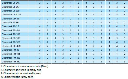
119 Table 61: Demulsifier functionality guide. [29] 118
![5.14 Wacker WACKER [56] is introducing a new silicone based product especially developed for low temperature applications.](/docs-images/89/97994943/images/120-0.jpg "Conventional demulsifiers have their best performance at temperatures over 40 C. At lower temperatures, performance and effectiveness deteriorate significantly.")
120 5.14 Wacker WACKER [56] is introducing a new silicone based product especially developed for low temperature applications. Conventional demulsifiers have their best performance at temperatures over 40 C. At lower temperatures, performance and effectiveness deteriorate significantly. WACKER SG 3377 is a silicone fluid demulsifier which performs at temperatures of 40 C and less. Due to its high surface activity, the additive breaks the emulsion rapidly and removes the water effectively. This improves both the crude oil and the effluent water quality significantly. WACKER SG 3377 reduces the water fractions in crude oil to one percent and minimizes the oil remnants in the waste water down to 10 ppm. It is claimed to be suitable for all international onshore and offshore applications. When mixed with conventional demulsifiers, it is an economically attractive and effective solution that permits the breaking of oil in areas where sufficient temperature is not available for the process, such as older wells or offshore drilling fields. [56] 5.15 Low Temperature Demulsifiers separate waxy crude oil in Mumbai Offshore According to the project of Sundriyal, Agrawal, Jain, and Mehrotra [47] in the regional Geoscience laboratory in New Delhi in India, 35 Low Temperature Demulsifier (LTD) samples from 10 reputed suppliers were evaluated at laboratory for performance on fresh emulsions at 35 and 40 C. Field trial orders were placed to five suppliers whose samples passed the laboratory selection criterion and these samples were field tried and performance was monitored for the specified parameters as shown in Table 62. [47] The produced oil is waxy in nature, it crystallizes at low temperature and more water traps within the oil. The formed emulsion is a W/O emulsion. Table 62: Laboratory and Field Performance Evaluation Criterion. [47] The physical and chemical characteristics of the crude oil are presented in Table 63 for the years 2004 and The field becomes aged and the water content in liquid production has increased. 119
 at 35 and 40 C during bottle test are shown in Figures 83 & 84 respectively.")
121 Table 63: Physicochemical characteristics of the composite crude oil of ICP platform. [47] The performance of low temperature demulsifiers during laboratory evaluation with varying doses ( ppm) at 35 and 40 C during bottle test are shown in Figures 83 & 84 respectively. The performance is judged by determining the water content in the layer of the oil phase. Figure 83: Performance of LTD with varying doses at 35 C. [47] The desired demulsification efficiency which is above 65 % (Table 62) could be achieved at 20 ppm or more (Figure 84). [47] 120
![Figure 84: Efficiency of LTD at different doses at 40 C. [47] Table 64 presents the performance evaluation of selected five samples during field trial along with production and process parameters.](/docs-images/89/97994943/images/122-0.jpg "The performance of demulsifiers has been observed to be better when liquid production was in the range of 15,000-156,000 barrels/day.")
122 Figure 84: Efficiency of LTD at different doses at 40 C. [47] Table 64 presents the performance evaluation of selected five samples during field trial along with production and process parameters. The performance of demulsifiers has been observed to be better when liquid production was in the range of 15, ,000 barrels/day. Any increase beyond this range, resulted in deterioration of demulsifier performance. The performance of demulsifier Phasetreat-6621 evaluated in June 09 with liquid production 150,000 barrels/day has been found to be better as compared to performance of same demulsifier evaluated in the month of July 09 with liquid production 161,000 barrels/day. [47] 121
.")
123 Table 64: Comparative data of performance of low temperature demulsifiers. [47] According to Sundriyal, Agrawal, Jain and Mehrotra [47] the narrow range variation in separator temperature has no significant effect on the performance of demulsifiers (Figure 85). This fact is reinforced by the field trial data of demulsifier DM-5 in which 86.9 % samples in Train A were observed with water content 0.2 % having curing temperature range C whereas 91.3 % samples in Train B were observed with water content 0.2 % having curing temperature range C. The curing temperature in Train B is 3 C less than Train A, however higher number (91.3 %) samples in Train B were found with water content 0.2 % as compared to 86.9 % in Train A. Figure 85: Comprative performance of Low Temperature Demulsifier. [47] Finally, the researchers report the following conclusions: 122
124 1. The demulsification of crude oil emulsions at ICP platform can be successfully achieved by use of selected low temperature demulsifiers. 2. The water content in oil during lab evaluation as well as during field trial has been found to be within desired limit of less than 1 % (v/v). 3. Oil content in effluent water has been observed to higher than the required limit of 300 ppm (max) with all the samples which may be attributed to the insufficient retention time in separators and need augmenting the process facilities. [47] 123

125 6 SIMULATION OF TREATING EMULSIONS A direct observation of emulsion destabilization is not easy, due to the fact that the droplets in emulsions are extremely small, typically with diameters less than 50 μm. Numerous attempts have been made to understand the dynamic of dehydration process. The coalescence of droplets is a function of their contact time and the interface characteristics between the phases. Combining the collision frequency and coalescence efficiency results in the estimation of the coalescence frequency. [67] The models are only approximations of the reality and many assumptions should be imposed in order to build a simulation model. Some of the most common assumptions are the following: droplets are spherical, droplets of the same size class are broken at the same frequency and only once, all droplets of the same class size have the same residence time in the unit, the density of the emulsion is a linear function of the oil content, each mixture of oil and water forms an emulsion, so that there is not any limitation in the amount of emulsifiers present in the system, for a nozzle-like unit the pressure drop is the composite effect of shear stress and extensional flow. [67] The development of emulsion models capable of representing e.g. coalescence, are a subject of intense research. Several models are proposed in the literature for taking into account the different phase systems to improve the agreement between the simulation results and experimental data. As far as the multiphase flow simulation is concerned, there are many numerical approaches to choose for solving the population balance equation (PBE). Due to the easy application, reasonable accuracy and computational cost, the moment methods are preferable. They can couple the population balance with CDF codes. [68] Computational fluid dynamics (CFD) is a numerical simulation technique for the solution of fluid-flow in three dimensions. The CFD method allows modelling of the fluid dynamics of two immiscible fluids. CFD is also the name of the commercial software (Figure 86). Using the CFD Module of the CFD software, modelling is possible for most aspects of fluid flow, including compressible, nonisothermal, non-newtonian, multiphase, and porous media flows, all in the laminar and turbulent flow regimes. Several CFD research studies have been performed to simulate the emulsification process. [66] Figure 86: Flow distribution using CFD. SPE Webinar: 3-phase Separation: Identifying and addressing issues before they happen. [74] 124

126 ANSYS Fluent is a powerful commercial software for computational fluid dynamics (CFD) which empowers to go further and faster by optimizing the design by simulating complex phenomena. ANSYS includes well-validated physical modeling capabilities to deliver fast, accurate results across the widest range of CFD and multiphysics applications. [72] Figure 87: Correcting gas flow pattern using ANSYS Fluent. SPE Webinar: 3-phase Separation: Identifying and addressing issues before they happen. [74] Simulations are also a valuable tool in order to understand the role of surfactants in the stability of the emulsions. There are still severe computational restrictions for the simulation of emulsions. Apart from the large number of processes involved, [69] the number of surfactant molecules is very high even at dilute concentrations, so, it is not possible to simulate the movement of each surfactant molecule explicitly along with the movement of the drops. The time step of the simulation has to be very small in order to sample appropriately the potential of interactions between the drops. Drops of small size exhibit also a Brownian motion due to their thermal interaction with the solvent which has to be taken into account into the equation of motion. It is not possible to simulate the behavior of drops using constant potential values as it is done in molecular dynamics. The potential of molecular interaction changes with time as a consequence of the surfactant adsorption and the progressive decrease of interfacial area of the emulsion due to the coalescence of drops. This demands the frequent recalculation of the interfacial properties that determine the forces between the particles. A flowchart of emulsion stability simulation is illustrated in Figure
127 Figure 86: The algorithm for Emulsion Stability Simulations (ESS) in the form of flowchart. [69] Modelling and simulation techniques of the emulsion formation are investigated in many Universities in Europe (Germany and Netherlands) as well as in Latin America (Brazil and Venezuela) and Asia (China and Japan). The Institute for the Physics of Complex Systems in Dresden (Germany) investigates the mechanism of Ostwald ripening in emulsions and the role of chemical reactions on droplet dynamics in liquid phases. A general framework has been proposed to study such active emulsions both in finite and infinite systems. It has been shown that Ostwald ripening can be suppressed and emulsions are typically monodisperse when first-order chemical reactions are considered. The results were compared to numerical solutions. In the model of this Institute, emulsions can be stable despite large fluctuations caused by droplet coalescence and droplet nucleation. These effects will merely broaden the droplet size distribution. [73] In China, the University of Petroleum investigated the dehydration of a W/O emulsion subjected to an electric field. [70] The time evolution of the droplets subjected to an electric field was investigated by using an optical microscopy. Computer simulations of the dynamic behavior of the droplets were implemented based on the balance of forces applied on them. Figure 87 shows the computational results of the evolution of the droplets subjected to an electric field. 126

![[71] New models for the coalescence of droplets and for the breakage of the emulsions.](/docs-images/89/97994943/images/128-1.jpg "Experimental data are produced for the flow calculation of W/O emulsions.")
.")

128 Figure 87: Evolution of the droplets subjected to an electric field. [70] The University of Chemical Engineering in Rio de Janeiro has proposed new models. [71] New models for the coalescence of droplets and for the breakage of the emulsions. Experimental data are produced for the flow calculation of W/O emulsions. The experimental flow takes place through a duct with a square cross section and three movable drawers, which generate a localized pressure drop similarly to a valve (Figure 88). Figure 88: A duct with a square cross section and three movable drawers. [71] The simulated contour plot for the volumetric phase fraction is illustrated in Figure 89. The simulated results show large values of the dispersed-phase fraction in regions where recirculation zones entrap the droplets. Figure 89: Contour plot for the volumetric phase fraction. [71] Despite the large number of works published in the literature the development of models is still a significant subject for future research. 127
Aegis Tech Line Aegis Chemical Solutions Technical Newsletter Volume 06, June 2018
 EMULSIONS IN OIL PRODUCTION CRUDE OIL SPECIFICATIONS Pipeline Operators and Refiners set specifications on the quantity of basic sediment and water (BS&W) in the crude oil that enters their equipment and
This is an author produced version of Asphaltene-stabilized emulsions: an interfacial rheology study.
 This is an author produced version of Asphaltene-stabilized emulsions: an interfacial rheology study. White Rose Research Online URL for this paper: http://eprints.whiterose.ac.uk/94812/ Proceedings Paper:
Preparation and evaluation of demulsifiers agents for Basra crude oil
 Appl Petrochem Res (212) 1:29 33 DOI 1.7/s1323-11-3-1 ORIGINAL ARTICLE Preparation and evaluation of demulsifiers agents for Basra crude oil Hikmeat Abd Al-Raheem Ali Received: 2 July 211 / Accepted: 23
Low Temperature Demulsifier, its Application & Results
 Low Temperature Demulsifier, its Application & Results S. P. Garg, Dr. A. K. Gupta & Dr. N. K. Kapoor Chemistry Section, Neelam & Heera Asset, ONGC, Mumbai ABSTRACT Breaking oil emulsion in areas where
Stability of Food Emulsions (2)
") Stability of Food Emulsions (2) David Julian McClements Biopolymers and Colloids Laboratory Department of Food Science Droplet Coalescence Oiling Off Coalescence Aggregation due to fusing together of two
Stability of Food Emulsions (2) David Julian McClements Biopolymers and Colloids Laboratory Department of Food Science Droplet Coalescence Oiling Off Coalescence Aggregation due to fusing together of two
Research Journal of Chemistry and Environment Vol.15 (3) Sept (2011) Res.J.Chem.Environ.
 Sept (2011) Res.J.Chem.Environ.") Demulsification of Triton X-100, Low-Sulfur Wax Residue (LSWR), Sorbitan Monooleate (Span 83) and Sodium Dodecyl Sulfate (SDS)-Stabilized Petroleum Emulsions with a Microwave Separation Method Abdulbari
Demulsification of Triton X-100, Low-Sulfur Wax Residue (LSWR), Sorbitan Monooleate (Span 83) and Sodium Dodecyl Sulfate (SDS)-Stabilized Petroleum Emulsions with a Microwave Separation Method Abdulbari
OIL AND WATER SEPARATION AT ITS BEST
 OIL AND WATER SEPARATION AT ITS BEST Looking for faster and more efficient separation of produced water from crude oil as well as increased production? Vessel Internal Electrostatic Coalescers (VIEC) have
Experiment 13 Preparation of Soap
 Experiment 13 Preparation of Soap Soaps are carboxylate salts with very long hydrocarbon chains. Soap can be made from the base hydrolysis of a fat or an oil. This hydrolysis is called saponification,
Demulsifying Water-in-Bitumen Emulsions of Oil Sands Froth Treatment. Chemical Engineering
 Demulsifying Water-in-Bitumen Emulsions of Oil Sands Froth Treatment by Liang Chen A thesis submitted in partial fulfillment of the requirements for the degree of Master of Science in Chemical Engineering
Application Report. Interfacial rheology, water-in-oil emulsions, demulsifier, crude oil processing, corrosion
 Application Report Application report: AR276 Industry section: Oil recovery Author: IK, DF, RM, TW, MK Date: 07/2015 Method: Drop Shape Analyzer DSA30R Keywords: Interfacial rheology, water-in-oil emulsions,
Industrial Waxes Chemistry & Blending
 Industrial Waxes Chemistry & Blending Sasol Performance Chemicals About us About us Sasol s Performance Chemicals business unit markets a broad portfolio of organic and inorganic commodity and speciality
13 Congresso Internacional de Tintas 13ª Exposição Internacional de Fornecedores para Tintas
 HIGH PERFORMANCE ADDITIVES FOR WATER BASED AND LOW VOC PAINTS AND COATINGS Daniel de Moura Massarente, Wolfgang Geuking Croda Coatings and Polymers The replacement of solvent-based coatings by water based
Preparation and Properties of Soap
 Preparation and Properties of Soap Experiment #6 Objective: To prepare soap by alkaline hydrolysis (saponification) of natural fats and test some of the chemical properties and cleansing power of soap
Asphalt ( Bitumen ) Chemistry and Emulsion Performance. Glynn and Irina Holleran
 Chemistry and Emulsion Performance. Glynn and Irina Holleran") Asphalt ( Bitumen ) Chemistry and Emulsion Glynn and Irina Holleran INTRODUCTION Bitumen Chemistry 1 Outline Bitumen Chemistry Processing and Crudes in NZ Imported Bitumen New Zealand Bitumen Chemistry
Asphalt ( Bitumen ) Chemistry and Emulsion Glynn and Irina Holleran INTRODUCTION Bitumen Chemistry 1 Outline Bitumen Chemistry Processing and Crudes in NZ Imported Bitumen New Zealand Bitumen Chemistry
CH 2 OH CHOH. gycerol
 Synthesis and Environmental Impact of Soap and Detergents Your group has been sent to a remote mountain region where life is still primitive. Here, the people still use traditional lye soaps, which have
EOR Produced Emulsion Separation
 EOR Produced Emulsion Separation George J. Hirasaki, Clarence A. Miller, Olina G. Raney April 2011 Produced Brine Composition (SP) 1 wt.% NaCl 500 ppm Ca++ 1200 ppm SNF Polymer FLOPAAM 3330S 0.15 wt% Neodol
Preparation and Properties of Soap Experiment #7
 Preparation and Properties of Soap Experiment #7 Objective: To prepare soap by alkaline hydrolysis (saponification) of natural fats and test some of the chemical properties and cleansing power of soap
ADHEBIT Adhesion Promoters
 ADHEBIT Adhesion Promoters A new generation of adhesion promoters that combines superior coating and exceptional workability with immediate commercial saving The life of an asphalt pavement depends basically
 This article was originally published in a journal published by Elsevier, and the attached copy is provided by Elsevier for the author s benefit and for the benefit of the author s institution, for non-commercial
DS-CD-01 Rev 3
 Coalescers OVERVIEW There are numerous industrial applications requiring effective physical separation of two process liquids. HAT has developed a number of AlphaSEP Coalescers to handle a wide range of
A guide to droplet generation
 A guide to droplet generation 2 Contents INTRODUCTION... 4 Droplet generators... 4 A choice of designs... 4 DROPLET GENERATION... 5 Droplet generator geometry... 5 Flow rate control... 5 Droplet sizes
Study on The Effect of Demulsifers on Crude oil and Petroleum Products
 Int. J. Environ. Res., ():-, Spring ISSN: - Study on The Effect of Demulsifers on Crude oil and Petroleum Products Dimitrov, A. N. *, Yordanov, D. I. and Petkov, P. S. Department of Industrial Technologies
Manufacture of Cast Products
 Manufacture of Cast Products When a layer of rubber is deposited on the interior surface of a hollow mould, it is known as casting. The latex products obtained by the casting process are hollow and toys,
Offset Inks - Basics
 Offset Inks - Basics Lithographic inks are paste inks, The press works the ink, thereby heating it and reducing its viscosity or body, making it flow readily to provide a uniform ink film to the image
Subject : Dyeing And Printing. Unit 5: Dyeing process for natural fibers. Quadrant 1 E-Text
 Subject : Dyeing And Printing Unit 5: Dyeing process for natural fibers Quadrant 1 E-Text Learning Objectives The learning objectives of this unit are: Describe the dyeing process for cellulosic fibers
THE EFFECT OF PARAFFIN WAX TO PROPERTIES OF RADIATION VULCANIZATION NATURAL RUBBER LATEX (RVNRL)
") THE EFFECT OF PARAFFIN WAX TO PROPERTIES OF RADIATION VULCANIZATION NATURAL RUBBER LATEX (RVNRL) Mohd Noorwadi Mat Lazim, Sofian Ibrahim, Muhammad Saiful Omar, Khairul Hisyam Mohamed Yusop, Chai Chee Keong,
THE EFFECT OF PARAFFIN WAX TO PROPERTIES OF RADIATION VULCANIZATION NATURAL RUBBER LATEX (RVNRL) Mohd Noorwadi Mat Lazim, Sofian Ibrahim, Muhammad Saiful Omar, Khairul Hisyam Mohamed Yusop, Chai Chee Keong,
COPYRIGHT. Separation Core. Principles and Equipment of Gas-Liquid Separation. By the end of this lesson, you you will will be able be able to: to:
 6/20/2017 Learning Objectives Separation Core Principles and Equipment of Gas-Liquid Separation By the end of this lesson, you you will will be able be able to: to: Describe separator applications and
Interaction between Icelandic basalt and Swedish granite with Swedish bitumen emulsion
 DEGREE PROJECT IN CHEMICAL SCIENCE AND ENGINEERING, SECOND CYCLE, 30 CREDITS STOCKHOLM, SWEDEN 2018 Interaction between Icelandic basalt and Swedish granite with Swedish bitumen emulsion Is it possible
PERFORM CHEMISTRY TO ACHIEVE FULL FIELD POTENTIAL
 PERFORM CHEMISTRY TO ACHIEVE FULL FIELD POTENTIAL MAXIMIZE PRODUCTION FROM RESERVOIR TO REFINERY UNLOCK POTENTIAL, OPTIMIZE PRODUCTION Schlumberger provides integrated production technology services that
Phase Separation of Water in Oil Emulsion Using Electro-Pulse Inductive Coalescer
 Phase Separation of Water in Oil Emulsion Using Electro-Pulse Inductive Coalescer Ezadin. B. Farhat Alkateb*, Dr. Satyendra Nath, Prof. A. K. Nema *Research Scholar, Department of Environmental Science,
Bitumen Recovery from Indonesian Oil Sands Using ASP (Alkali, Surfactant and Polymer) Agent
 Agent") Process Research China Petroleum Processing and Petrochemical Technology 2018, Vol. 20, No. 1, pp 110-115 March 30, 2018 Bitumen Recovery from Indonesian Oil Sands Using ASP (Alkali, Surfactant and Polymer)
Process Research China Petroleum Processing and Petrochemical Technology 2018, Vol. 20, No. 1, pp 110-115 March 30, 2018 Bitumen Recovery from Indonesian Oil Sands Using ASP (Alkali, Surfactant and Polymer)
Evaluation of Demulsifiers by Modified Thin Liquid Film Technique. Xinrui Ma
 Evaluation of Demulsifiers by Modified Thin Liquid Film Technique By Xinrui Ma A thesis submitted in partial fulfillment of the requirements for the degree of Master of Science in Chemical Engineering
 A Research article on - Benefits of Glauber s salt in Textile Wet processing 1. Introduction: By: Sushil Kumar Hada In order to understand the depth of the subject, one should understand the basics behind
Color-Fixing. Agent Organoleptic Feeling1 #
 Synthesis and Application of Cationic Color-Fixing Agent for leathers with Excellent Organoleptic Feeling1 # Shufa Qin, Keyong Tang College of Materials Science and Engineering, Zhengzhou University, Zhengzhou
Additive - any substance added in small quantities to another substance, usually to improve properties.
 Glossary Golden Artist Colors, Inc. 188 Bell Road New Berlin, NY 13411-9527 USA Toll Free: 800-959-6543 Fax: 607-847-6767 techsupport@goldenpaints.com www.goldenpaints.com Acrylics - resins resulting from
Setamol Disperse ws. Technical Information. Universal, anionic dispersing agent for dyes, and protective colloid. TI/T June 2011 Page 1 of 5
 Technical Information TI/T June 2011 Page 1 of 5 = Registered trademark of BASF SE Setamol Disperse ws Universal, anionic dispersing agent for dyes, and protective colloid TI/T June 2011 Page 2 of 5 Setamol
Saponification and the Making of Soap - An Example of Basic Catalyzed Hydrolysis of Esters
 1 of 5 9/7/2010 2:56 PM Experiment 8 Saponification and the Making of Soap - An Example of Basic Catalyzed Hydrolysis of Esters Objectives In today's experiment, we will perform a reaction that has been
Articles and Abstracts. Roger Graves, Director of Writing Across the Curriculum and Heather Graves Associate Professor, English and Film Studies
 Articles and Abstracts Roger Graves, Director of Writing Across the Curriculum and Heather Graves Associate Professor, English and Film Studies http://www.ualberta.ca/~graves1/index.html Roger Graves http://www.humanities.ualberta.ca/wac/
Pall Coalescers Bring Down Costs Through Advanced Phase Separation Technology
 Pall Coalescers Bring Down Costs Through Advanced Phase Separation Technology Pall Phase Separation Technology for Control and Protection of Your Plant Every year refineries, gas processing plants, and
A5EE-337 DURABILITY OF A BITUMEN IN A HOT MIX ASPHALT: CONSEQUENCES OF OVER-HEATING AT THE MIXING PLANT
 A5EE-337 DURABILITY OF A BITUMEN IN A HOT MIX ASPHALT: CONSEQUENCES OF OVER-HEATING AT THE MIXING PLANT Carole Gueit, Michel Robert Colas Campus for Sciences and Techniques, Road Chemistry service, Magny-les-Hameaux,
Liquid-Liquid Extraction
 Typical Column Arrangements ARRANGEMENT FOR LIGHT LIQUID DISPERSED OPERATION ARRANGEMENT FOR HEAVY LIQUID DISPERSED OPERATION AlphaSEP DM Coalescer Coalescer Pad P+ Packing PD PLD Feed 300 Feed Distributor
AIR-RECTIFIED BITUMNEN
 Bitumen Glossary A AIR BLOWING The process by which compressed air is blown into a feedstock, which may include VACUUM RESIDUE, PROPANE-PRECIPITATED ASPHALT mixed with ATMOSPHERIC RESIDUE, and/or a FLUX
Fat Crystals Influence Methylcellulose Stabilization of Lipid Emulsions
 DOI 10.1007/s11746-016-2933-3 SHORT COMMUNICATION Fat Crystals Influence Methylcellulose Stabilization of Lipid Emulsions A. E. Thiel 1 R. W. Hartel 1 P. T. Spicer 2 Received: 18 August 2016 / Revised:
TURBULENT SETTLING (TS) TECHNOLOGY FOR SOLVENT EXTRACTION
 TECHNOLOGY FOR SOLVENT EXTRACTION") TURBULENT SETTLING (TS) TECHNOLOGY FOR SOLVENT EXTRACTION By Y. Kokotov*, L. Braginsky*, D. Shteinman*, E. Slonim *, V. Barfield **, B. Grinbaum ** * Turbulent Technologies Ltd. Israel ** Bateman Advanced
TURBULENT SETTLING (TS) TECHNOLOGY FOR SOLVENT EXTRACTION By Y. Kokotov*, L. Braginsky*, D. Shteinman*, E. Slonim *, V. Barfield **, B. Grinbaum ** * Turbulent Technologies Ltd. Israel ** Bateman Advanced
A Novel Surgery-like Strategy for Droplet Coalescence in Microchannels
 Supplementary Material (ESI) for Lab on a Chip A Novel Surgery-like Strategy for Droplet Coalescence in Microchannels Supplementary material Nan-Nan Deng, a Shao-Xing Sun, a Wei Wang, a Xiao-Jie Ju, a
Beverage industries use coldrolled
 CASE HISTORY Di-Octyl Sebacic Acid in Epoxy Paint Leads to Blistering in a Drum and Barrel Manufacturing Plant TAPAN K. ROUT AND KINSHUK ROY, Tata Steel, Ltd. Di-octyl sebacic acid (DOS-A) is used as rust
1.Pretreatment auxiliary
 1.Pretreatment auxiliary Guangzhou Lang's Chemical Additives Co.,Ltd Tel.:86-20-61164351/15817170571 E-mail: gzlanger2010@yahoo.com Add.:Room 2C11,Bldg.1,Factory No. 32, Helong 1st Road, Baiyun District
Chemistry behind good feelings
 Chemistry behind good feelings Contents Levelling & Dispersing Agent for Polyester Dyeing Saragen-DLN Water & Oil Repellent for Synthetic Fabric Newguard-AC Hydrophillic Silicone Softener Xtrasoft-832
Asphalt Emulsion Basics
 Asphalt Emulsion Basics National Pavement Preservation Conference Nashville, TN Aug 29, 2012 DELTA BLUES CREDIT Alan James, Akzo Nobel Overview of Asphalt Emulsion TRB Circular E-C102 Moving Asphalt
Uniperol EL. Technical Information. Nonionic dispersing agent, emulsifier and leveling agent for use in textile dyeing and printing processes.
 Technical Information Uniperol EL September 1999 Nonionic dispersing agent, emulsifier and leveling agent for use in textile dyeing and printing processes. Colorants and Finishing Products Nature Ethoxylation
2-10 µm Diameter Water Droplets in Mineral Oil Emulsion Production
 2-10 µm Diameter Water s in Mineral Oil Emulsion Production Dolomite s Generation System - Small s Application Note Page SHPT-487168127-264_v.2.0 Summary 2 Flow Focussing Based Production 3 Experimental
Dekol Disperse SN S. Technical Information
 Technical Information TI/T Asia Feb 2012 Page 1 of 6 = Registered trademark of BASF SE Dekol Disperse SN S Dispersing agent, protective colloid and complexing agent for use in all stages of dyeing processes
4728 Gravois Ave. St. Louis, MO SIMAX
 http://www.stemmerich.com 4728 Gravois Ave. St. Louis, MO 63116 314-832-7726 SALES 800-325-9528 FAX 314-832-7799 SIMAX DESCRIPTION: In 1837 The Kavalier Glassworks was established, and it has been making
Contents. NIIR Project Consultancy Services (NPCS) 1/6
 1/6") The Complete Book on Resins (Alkyd, Amino, Phenolic, Polyurethane, Epoxy, Silicone, Acrylic), Paints, Varnishes, Pigments & Additives (Surface Coating Products with Formulae)(3rd Revised Edition) Author:
The Complete Book on Resins (Alkyd, Amino, Phenolic, Polyurethane, Epoxy, Silicone, Acrylic), Paints, Varnishes, Pigments & Additives (Surface Coating Products with Formulae)(3rd Revised Edition) Author:
Introduction. Developed by: K. Moore, J. Giannini, K. Nordstrom & W. Losert (Univ. of Maryland, College Park) Page 1
 Page 1") TA GUIDE Lab 7: How do charged objects in a fluid interact with each other and respond to external electric fields? Electrophoresis and Charge Screening in Fluids. Introduction In this two-week lab, students
TA GUIDE Lab 7: How do charged objects in a fluid interact with each other and respond to external electric fields? Electrophoresis and Charge Screening in Fluids. Introduction In this two-week lab, students
Handbook on Textile Auxiliaries, Dyes and Dye Intermediates Technology
 Handbook on Textile Auxiliaries, Dyes and Dye Intermediates Technology Author: NPCS Board of Consultants & Engineers Format: Paperback ISBN: 9788178331225 Code: NI221 Pages: 736 Price: Rs. 1,575.00 US$
Basic Principles and Operation of Transformer
 Basic Principles and Operation of Transformer CONSTRUCTIONAL ASPECTS Cores In order to enhance core s magnetic properties, it is constructed from an iron and silicon mixture (alloy). The magnetic core
Chapter 07 Haloalkanes
 2016 Gregory ook 2016 Gregory ook 2016 Gregory ook 2016 Gregory ook 2016 Gregory ook 2016 Gregory ook hapter 07 aloalkanes Alkyl alides rganic halogen compounds are found in many places from common solvents
Presented at 24th AEMA Meeting, March 14-16, 1997, Cancun, Mexico
 Presented at 24th AEMA Meeting, March 14-16, 1997, Cancun, Mexico Solving Emulsion Viscosity Problems by the Choice of Emulsifier Alan James, Akzo Nobel Chemicals. Abstract Viscosity and settlement are
Ink Systems for the Xaar Ink Jet Printhead
 Ink Systems for the Xaar Ink Jet Printhead John D. Schofield Zeneca Specialties Manchester, UK Abstract Advantages of the oil-based pigmentary inks in the Xaar printhead 1,2, when compared with conventional
Textile Industry Dyeing process
 Anticrease L Antifelt Antifoam 22 Antimig Antiredox AR Blocker PAN Blocker WN Buffer 700 Anticrease agent, softening and slippering. Suitable for processs on every type of fibre and yarns. Recommended
DEVELOPMENT OF NEW GREEN DEMULSIFIER COMPOSITION FOR OIL PRODUCTION
 DEVELOPMENT OF NEW GREEN DEMULSIFIER COMPOSITION FOR OIL PRODUCTION IBRAHIM, BELLO GARKO (KKE 12012) Masters of chemical Engineering with Entrepreneurship UNIVERSITI MALAYSIA PAHANG i DEVELOPMENT OF NEW
New Technologies for Clear Air Care Applications
 New Technologies for Clear Air Care Applications 1 Topics Definitions Progression of Technology How Gels are Formed Properties of Modified Polyamide Gellants Performance in Container Candles and Pillar
S. E. Lorimer and B. T. Ellison Shell Deepwater Development Inc. P. O. Box New Orleans, LA
 Paper 60C Subsea Oil System Design and Operation to Manage Wax, Asphaltenes, and Hydrates S. E. Lorimer and B. T. Ellison Shell Deepwater Development Inc. P. O. Box 60833 New Orleans, LA 70160-0833 Prepared
SOAP. A brief discussion on the History, Base Construction, Formulating and Manufacturing
 SOAP A brief discussion on the History, Base Construction, Formulating and Manufacturing HISTORY Said to be oldest hand manufactured product by mankind Improved hygiene Reduced infection and disease Twincraft
Target Markets. Water-based inks
 Styrene Maleic Anhydride Ester Copolymers and the New SMA 1550H Pigment Dispersants for Waterborne Benefits Improved color strength Improved dispersion stability and viscosity control Excellent compatibility
State of the Art in Grout Mixes
 State of the Art in Grout Mixes Presented By: James A. Davies, P.Eng. Advanced Construction Techniques Ltd. 3935 Lloydtown Aurora Road Kettleby, Ontario L0G 1J0 Toll Free Telephone: 877-373-7248 Email:
Silicon Materials for Oil & Gas Applications
 Silicon Materials for Oil & Gas Applications 1 Momentive Performance Materials: An industry leader in diesel fuel foam control First to launch a new range of Silbreak* silicone demulsifiers for upstream
OIL & GAS PRODUCTION & TREATMENT TECHNOLOGIES K-SEP SEPARATOR INTERNALS SEPARATOR & ELECTROSTATIC TREATER INTERNALS, DESIGNS AND SOFTWARE
 OIL & GAS PRODUCTION & TREATMENT TECHNOLOGIES K-SEP SEPARATOR INTERNALS SEPARATOR & ELECTROSTATIC TREATER INTERNALS, DESIGNS AND SOFTWARE www.kirkprocess.com 3 DECADES OF EXPERIENCE DESIGNING OIL & GAS
INTERFACIAL CHEMISTRY ASPECTS OF DE-INKING FLOTATION OF MIXED OFFICE PAPER
 Preprint 01-9 INTERFACIAL CHEMISTRY ASPECTS OF DE-INKING FLOTATION OF MIXED OFFICE PAPER J. Drelich, J. Pletka, P. Boyd, E. Raber, D. Herron, E. Luhta, H. Walqui, N. Tervo, S. Boston, J. Wieland, J. Morgan,
Long Run Length Positive Thermal CTP System XL-T
 Long Run Length Positive Thermal CTP System XL-T Norio AOSHIMA*, Noriaki WATANABE*, Shigekatsu FUJII**, Takashi ARIDOMI***, Yoichiro ARA*, Mamoru KURAMOTO*, Yoshinori TAGUCHI****, and Yuichi YASUHARA*****
Pavement materials: Bitumen
 Pavement materials: Bitumen Lecture Notes in Transportation Systems Engineering Prof. Tom V. Mathew Contents 1 Overview 1 1.1 Production of Bitumen............................... 2 1.2 Vacuum steam distillation
Subject: Dyeing and Printing. Unit 7: Introduction to textile printing. Quadrant 1 e-text
 Subject: Dyeing and Printing Unit 7: Introduction to textile printing Quadrant 1 e-text Learning Objectives The learning objectives of this unit are: Review the methods of printing textiles. 7.1 INTRODUCTION
A Waterborne Self Cross Linking Binder for Designing Coatings with Excellent Chemical and Blocking Resistance
 A Waterborne Self Cross Linking Binder for Designing Coatings with Excellent Chemical and Blocking Resistance Gun Lundsten CH-Polymers OY, Raisionkaari 55, 21200 Raisio, Finland, e-mail: gun.lundsten@ch-polymers.com
AffiAmino UltraRapid Agarose
 Product no 1003 AffiAmino UltraRapid Agarose Product Information Lab on a Bead AB Edition 20151030 All rights reserved Copyright 2015 Lab on a Bead AB Table of Contents 1. General information... 3 2. Principle
COLOR COMPATIBILITY AND COLOR DEVELOPMENT: A major formulation challenge for architectural paints
 Full Additives Spectrum for improved of Defoamer color Offerings for acceptance Automotive in paints Plastisol and Applications coatings COLOR COMPATIBILITY AND COLOR DEVELOPMENT: A major formulation challenge
Soap Fabrication. 1. Introduction [1]
![Soap Fabrication. 1. Introduction [1]](/thumbs/82/86094217.jpg "Soap Fabrication. 1. Introduction [1]") 1. Introduction [1] Soap Fabrication The main uses of soap include bathing, washing, cleaning and other types of housekeeping. Soap acts as surfactant because it has surface active properties. When Soaps
1. Introduction [1] Soap Fabrication The main uses of soap include bathing, washing, cleaning and other types of housekeeping. Soap acts as surfactant because it has surface active properties. When Soaps
TPi TPi. Model. Tilted Plate Interceptor Concrete Oil Water Separators
 Model Tilted Plate Interceptor Concrete Oil Water Separators The Series oil water separators are designed per the American Petroleum Institute (API) separator design guidelines The Series Tilted Plate
Discover and enjoy Fast Flash purifications offered by EasyVarioFlash cartridges!
 Discover and enjoy Fast Flash purifications offered by EasyVarioFlash cartridges! EasyVarioFlash cartridges offer the latest improvements in Flash cartridges design. Based on the "Ready-to-Connect" concept,
Index. Page numbers in bold refer to figures and page numbers in italic refer to tables.
 Index Page numbers in bold refer to figures and page numbers in italic refer to tables. Air permeance 66, 135-6 AFM 60,60-1 'Apron size press' 84, 85 Atomic force microscopy (AFM) 60,60- Barrier dispersion
Paper Ink Preparation by Three Roll Mill
 Paper Ink Preparation by Three Roll Mill 1. INTRODUCTION Printing of one form or another has been with us for centuries and whilst the technologies of both the printing process and the ink formulations
IMPROVEMENT OF SHEAR STRENGTH OF SOIL USING BITUMEN EMULSION
 International Journal of Civil Engineering and Technology (IJCIET) Volume 7, Issue 6, November-December 216, pp. 156 165, Article ID: IJCIET_7_6_17 Available online at http://www.iaeme.com/ijciet/issues.asp?jtype=ijciet&vtype=7&itype=6
Acid dyes:- Introduction
 TOPIC-I DYEING OF WOOL WITH ACID DYES Acid dyes:- Introduction Acid dyes are highly water soluble, and have better light fastness than basic dyes.the textile acid dyes are effective for protein fibers
MCEN Flow Visualization Group Project 01 Report
 MCEN-4228-010 Flow Visualization Group Project 01 Report By Group Phi Kane Chinnel, Corey Davis, and David Ramirez Section Instructor: Jean R. Hertzberg March 11, 2009 Introduction The purpose of the first
Ansell Chemical Guardian Portal
 Ansell Chemical Guardian Portal Oct 16, 2017 Legend (min) < 10 Not Recommended 10-30 Splash Protection Permeation breakthrough times evaluate the time necessary for a chemical to pass through a glove material
Factors Affecting Quick Lime Consumption In Dry FGD
 Factors Affecting Quick Lime Consumption In Dry FGD By: Mohamad Hassibi Chemco Systems, L.P. April, 2007 Revised: November, 2015 It has been an ongoing discussion as to what affects lime consumption in
Table of Contents. DyeTechs Dyeing Chemicals Dye and Pigment Fixatives... 9 Dyeing Auxiliaries... 9 Process Specialties... 9
 Table of Contents Page Number PrepTechs Preparation Chemicals Wetting and Penetrating Agents... 2 Desizing Agents... 2 Bleaching Auxiliaries... 2 Depilling Enzymes... 2 After Washing Detergents... 2 ElasTechs
LIST OF PUBLISHED STANDARDS
 Report : 07--5 Page o : Of 6 LIST OF PUBLISHED STDRDS Total Count: 8 umber SS umber pproved mendment SBS/TC 006 SBS/TC 006/SC 0 SS :008.0 Wax polish, solvent-based, for floors and furniture 008-08-5 008-08-5
PETROLEUM ENGINEERING
 PETROLEUM ENGINEERING Subject Code: PE Course Structure Sections/Units Section 1 Section 2 Section 3 Section 4 Linear Algebra Calculus Differential equations Complex variables Topics Section 5 Section
Helizarin Binder TOW Plus
 Technical Information TI/T Asia June 2011 Page 1 of 6 = Registered trademark of BASF SE Helizarin Binder TOW Plus Acrylic binder for pigment printing. The prints are fast to dry cleaning, have a pleasingly
Studies in Properties of Microcrystalline and Paraffin Waxes with the Help of Gas Chromatography (GC), DSC, FT-IR and by Conventional Methods
, DSC, FT-IR and by Conventional Methods") 2017 IJSRST Volume 3 Issue 8 Print ISSN: 2395-6011 Online ISSN: 2395-602X Themed Section: Scienceand Technology Studies in Properties of Microcrystalline and Paraffin Waxes with the Help of Gas Chromatography
2017 IJSRST Volume 3 Issue 8 Print ISSN: 2395-6011 Online ISSN: 2395-602X Themed Section: Scienceand Technology Studies in Properties of Microcrystalline and Paraffin Waxes with the Help of Gas Chromatography
SPEEK/PVA Polymer Films
 Supporting Information Photogeneration of H 2 O 2 in Water-Swollen SPEEK/PVA Polymer Films PaviElle Lockhart, 1 Brian K. Little, 1, B. L. Slaten 2 and G. Mills* 1 Department of Chemistry and Biochemistry,
International Journal of Engineering & Technology IJET-IJENS Vol: 12 No: 01 5
 International Journal of Engineering & Technology IJET-IJENS Vol: 12 No: 01 5 Advantages of Prewashed 100 % cotton knit fabric over Scoured Bleached fabric in deep color Reactive dyeing process. Asma Begum
SEPARATOR INTERNALS. jci-group.com. Filtration & Separation Solutions. JCI Filtration & Separation Inc. JCI Cyclonics Ltd. JCI Sand Separators Ltd.
 TM Filtration & Separation Solutions SEPARATOR INTERNALS JCI Filtration & Separation Inc. JCI Cyclonics Ltd. JCI Sand Separators Ltd. jci-group.com JCI group of companies engineer and fabricate filtration
Module 11: Photolithography. Lecture11: Photolithography - I
 Module 11: Photolithography Lecture11: Photolithography - I 1 11.0 Photolithography Fundamentals We will all agree that incredible progress is happening in the filed of electronics and computers. For example,
CHEMICAL DEMULSIFICATION OF MODEL WATER-IN-OIL EMULSIONS WITH LOW WATER CONTENT BY MEANS OF IONIC LIQUIDS
 Brazilian Journal of Chemical Engineering ISSN 14-6632 Printed in Brazil www.abeq.org.br/bjche Vol. 34, No. 1, pp. 273-282, January - March, 217 dx.doi.org/1.159/14-6632.217341s215583 CHEMICAL DEMULSIFICATION
Study of Parameters Affecting Size Distribution of Beads Produced from Electro-Spray of High Viscous Liquids
 Iranian Journal of Chemical Engineering Vol. 6, No. 3 (Summer), 2009, IAChE Resea rch note Study of Parameters Affecting Size Distribution of Beads Produced from Electro-Spray of High Viscous Liquids H.
Droplet Junction Chips
 Unit 1, Anglian Business Park, Orchard Road, Royston, Hertfordshire, SG8 5TW, UK T: +44 (0)1763 242491 F: +44 (0)1763 246125 E: sales@dolomite-microfluidics.com W: www.dolomite-microfluidics.com Dolomite
ORGANISATION AFRICAINE DE LA PROPRIETE INTELLECTUELLE
 19 ORGANISATION AFRICAINE DE LA PROPRIETE INTELLECTUELLE 11 N 8 51 Inter. CI. C10G 1/04; C10C 3/00 FASCICULE DE BREVET D INVENTION 21 22 Numéro de dépôt : 1201400181 (PCT/IB12/055849) Date de dépôt : 24/10/2012
TPi TPi. Model. Tilted Plate Interceptor Steel Oil Water Separators
 Model Tilted Plate Interceptor Steel Oil Water Separators The Series oil water separators are designed per the American Petroleum Institute (API) separator design guidelines The Series Tilted Plate Interceptors